US6282473B1 - System and method for controlling a vehicle occupant protection device - Google Patents
System and method for controlling a vehicle occupant protection deviceDownload PDFInfo
- Publication number
- US6282473B1 US6282473B1US09/455,731US45573199AUS6282473B1US 6282473 B1US6282473 B1US 6282473B1US 45573199 AUS45573199 AUS 45573199AUS 6282473 B1US6282473 B1US 6282473B1
- Authority
- US
- United States
- Prior art keywords
- occupant
- vehicle
- acceleration
- controller
- weight
- Prior art date
- Legal status (The legal status is an assumption and is not a legal conclusion. Google has not performed a legal analysis and makes no representation as to the accuracy of the status listed.)
- Expired - Lifetime
Links
- 238000000034methodMethods0.000titleclaimsdescription34
- 230000001133accelerationEffects0.000claimsdescription117
- 238000005070samplingMethods0.000claimsdescription22
- 230000003068static effectEffects0.000claimsdescription12
- 230000004044responseEffects0.000claimsdescription8
- 230000008569processEffects0.000description24
- 238000012512characterization methodMethods0.000description8
- 230000005484gravityEffects0.000description5
- 238000010586diagramMethods0.000description4
- 230000035945sensitivityEffects0.000description3
- 230000008859changeEffects0.000description2
- 239000012530fluidSubstances0.000description2
- 238000012986modificationMethods0.000description2
- 230000004048modificationEffects0.000description2
- 208000037063ThinnessDiseases0.000description1
- 230000005540biological transmissionEffects0.000description1
- 238000001514detection methodMethods0.000description1
- 238000005516engineering processMethods0.000description1
- 230000007257malfunctionEffects0.000description1
- 238000005259measurementMethods0.000description1
- 238000003909pattern recognitionMethods0.000description1
- 206010048828underweightDiseases0.000description1
Images


Classifications
- B—PERFORMING OPERATIONS; TRANSPORTING
- B60—VEHICLES IN GENERAL
- B60R—VEHICLES, VEHICLE FITTINGS, OR VEHICLE PARTS, NOT OTHERWISE PROVIDED FOR
- B60R21/00—Arrangements or fittings on vehicles for protecting or preventing injuries to occupants or pedestrians in case of accidents or other traffic risks
- B60R21/01—Electrical circuits for triggering passive safety arrangements, e.g. airbags, safety belt tighteners, in case of vehicle accidents or impending vehicle accidents
- B60R21/015—Electrical circuits for triggering passive safety arrangements, e.g. airbags, safety belt tighteners, in case of vehicle accidents or impending vehicle accidents including means for detecting the presence or position of passengers, passenger seats or child seats, and the related safety parameters therefor, e.g. speed or timing of airbag inflation in relation to occupant position or seat belt use
- B60R21/01512—Passenger detection systems
- B60R21/01542—Passenger detection systems detecting passenger motion
- B—PERFORMING OPERATIONS; TRANSPORTING
- B60—VEHICLES IN GENERAL
- B60R—VEHICLES, VEHICLE FITTINGS, OR VEHICLE PARTS, NOT OTHERWISE PROVIDED FOR
- B60R21/00—Arrangements or fittings on vehicles for protecting or preventing injuries to occupants or pedestrians in case of accidents or other traffic risks
- B60R21/01—Electrical circuits for triggering passive safety arrangements, e.g. airbags, safety belt tighteners, in case of vehicle accidents or impending vehicle accidents
- B60R21/015—Electrical circuits for triggering passive safety arrangements, e.g. airbags, safety belt tighteners, in case of vehicle accidents or impending vehicle accidents including means for detecting the presence or position of passengers, passenger seats or child seats, and the related safety parameters therefor, e.g. speed or timing of airbag inflation in relation to occupant position or seat belt use
- B60R21/01512—Passenger detection systems
- B60R21/01516—Passenger detection systems using force or pressure sensing means
- B—PERFORMING OPERATIONS; TRANSPORTING
- B60—VEHICLES IN GENERAL
- B60R—VEHICLES, VEHICLE FITTINGS, OR VEHICLE PARTS, NOT OTHERWISE PROVIDED FOR
- B60R21/00—Arrangements or fittings on vehicles for protecting or preventing injuries to occupants or pedestrians in case of accidents or other traffic risks
- B60R21/01—Electrical circuits for triggering passive safety arrangements, e.g. airbags, safety belt tighteners, in case of vehicle accidents or impending vehicle accidents
- B60R21/015—Electrical circuits for triggering passive safety arrangements, e.g. airbags, safety belt tighteners, in case of vehicle accidents or impending vehicle accidents including means for detecting the presence or position of passengers, passenger seats or child seats, and the related safety parameters therefor, e.g. speed or timing of airbag inflation in relation to occupant position or seat belt use
- B60R21/01512—Passenger detection systems
- B60R21/0153—Passenger detection systems using field detection presence sensors
- B60R21/01532—Passenger detection systems using field detection presence sensors using electric or capacitive field sensors
- B—PERFORMING OPERATIONS; TRANSPORTING
- B60—VEHICLES IN GENERAL
- B60R—VEHICLES, VEHICLE FITTINGS, OR VEHICLE PARTS, NOT OTHERWISE PROVIDED FOR
- B60R21/00—Arrangements or fittings on vehicles for protecting or preventing injuries to occupants or pedestrians in case of accidents or other traffic risks
- B60R21/01—Electrical circuits for triggering passive safety arrangements, e.g. airbags, safety belt tighteners, in case of vehicle accidents or impending vehicle accidents
- B60R21/015—Electrical circuits for triggering passive safety arrangements, e.g. airbags, safety belt tighteners, in case of vehicle accidents or impending vehicle accidents including means for detecting the presence or position of passengers, passenger seats or child seats, and the related safety parameters therefor, e.g. speed or timing of airbag inflation in relation to occupant position or seat belt use
- B60R21/01512—Passenger detection systems
- B60R21/0153—Passenger detection systems using field detection presence sensors
- B60R21/01534—Passenger detection systems using field detection presence sensors using electromagneticwaves, e.g. infrared
- B—PERFORMING OPERATIONS; TRANSPORTING
- B60—VEHICLES IN GENERAL
- B60R—VEHICLES, VEHICLE FITTINGS, OR VEHICLE PARTS, NOT OTHERWISE PROVIDED FOR
- B60R21/00—Arrangements or fittings on vehicles for protecting or preventing injuries to occupants or pedestrians in case of accidents or other traffic risks
- B60R21/01—Electrical circuits for triggering passive safety arrangements, e.g. airbags, safety belt tighteners, in case of vehicle accidents or impending vehicle accidents
- B60R21/015—Electrical circuits for triggering passive safety arrangements, e.g. airbags, safety belt tighteners, in case of vehicle accidents or impending vehicle accidents including means for detecting the presence or position of passengers, passenger seats or child seats, and the related safety parameters therefor, e.g. speed or timing of airbag inflation in relation to occupant position or seat belt use
- B60R21/01512—Passenger detection systems
- B60R21/0153—Passenger detection systems using field detection presence sensors
- B60R21/01536—Passenger detection systems using field detection presence sensors using ultrasonic waves
- B—PERFORMING OPERATIONS; TRANSPORTING
- B60—VEHICLES IN GENERAL
- B60R—VEHICLES, VEHICLE FITTINGS, OR VEHICLE PARTS, NOT OTHERWISE PROVIDED FOR
- B60R21/00—Arrangements or fittings on vehicles for protecting or preventing injuries to occupants or pedestrians in case of accidents or other traffic risks
- B60R21/01—Electrical circuits for triggering passive safety arrangements, e.g. airbags, safety belt tighteners, in case of vehicle accidents or impending vehicle accidents
- B60R21/015—Electrical circuits for triggering passive safety arrangements, e.g. airbags, safety belt tighteners, in case of vehicle accidents or impending vehicle accidents including means for detecting the presence or position of passengers, passenger seats or child seats, and the related safety parameters therefor, e.g. speed or timing of airbag inflation in relation to occupant position or seat belt use
- B60R21/01512—Passenger detection systems
- B60R21/01544—Passenger detection systems detecting seat belt parameters, e.g. length, tension or height-adjustment
- B60R21/01546—Passenger detection systems detecting seat belt parameters, e.g. length, tension or height-adjustment using belt buckle sensors
- B—PERFORMING OPERATIONS; TRANSPORTING
- B60—VEHICLES IN GENERAL
- B60R—VEHICLES, VEHICLE FITTINGS, OR VEHICLE PARTS, NOT OTHERWISE PROVIDED FOR
- B60R21/00—Arrangements or fittings on vehicles for protecting or preventing injuries to occupants or pedestrians in case of accidents or other traffic risks
- B60R21/01—Electrical circuits for triggering passive safety arrangements, e.g. airbags, safety belt tighteners, in case of vehicle accidents or impending vehicle accidents
- B60R21/015—Electrical circuits for triggering passive safety arrangements, e.g. airbags, safety belt tighteners, in case of vehicle accidents or impending vehicle accidents including means for detecting the presence or position of passengers, passenger seats or child seats, and the related safety parameters therefor, e.g. speed or timing of airbag inflation in relation to occupant position or seat belt use
- B60R21/01558—Electrical circuits for triggering passive safety arrangements, e.g. airbags, safety belt tighteners, in case of vehicle accidents or impending vehicle accidents including means for detecting the presence or position of passengers, passenger seats or child seats, and the related safety parameters therefor, e.g. speed or timing of airbag inflation in relation to occupant position or seat belt use monitoring crash strength
- B60R21/0156—Electrical circuits for triggering passive safety arrangements, e.g. airbags, safety belt tighteners, in case of vehicle accidents or impending vehicle accidents including means for detecting the presence or position of passengers, passenger seats or child seats, and the related safety parameters therefor, e.g. speed or timing of airbag inflation in relation to occupant position or seat belt use monitoring crash strength by deceleration
- B—PERFORMING OPERATIONS; TRANSPORTING
- B60—VEHICLES IN GENERAL
- B60R—VEHICLES, VEHICLE FITTINGS, OR VEHICLE PARTS, NOT OTHERWISE PROVIDED FOR
- B60R21/00—Arrangements or fittings on vehicles for protecting or preventing injuries to occupants or pedestrians in case of accidents or other traffic risks
- B60R21/01—Electrical circuits for triggering passive safety arrangements, e.g. airbags, safety belt tighteners, in case of vehicle accidents or impending vehicle accidents
- B60R21/015—Electrical circuits for triggering passive safety arrangements, e.g. airbags, safety belt tighteners, in case of vehicle accidents or impending vehicle accidents including means for detecting the presence or position of passengers, passenger seats or child seats, and the related safety parameters therefor, e.g. speed or timing of airbag inflation in relation to occupant position or seat belt use
- B60R21/01512—Passenger detection systems
- B60R21/01544—Passenger detection systems detecting seat belt parameters, e.g. length, tension or height-adjustment
- B60R21/01548—Passenger detection systems detecting seat belt parameters, e.g. length, tension or height-adjustment sensing the amount of belt winded on retractor
- B—PERFORMING OPERATIONS; TRANSPORTING
- B60—VEHICLES IN GENERAL
- B60R—VEHICLES, VEHICLE FITTINGS, OR VEHICLE PARTS, NOT OTHERWISE PROVIDED FOR
- B60R21/00—Arrangements or fittings on vehicles for protecting or preventing injuries to occupants or pedestrians in case of accidents or other traffic risks
- B60R21/02—Occupant safety arrangements or fittings, e.g. crash pads
- B60R21/16—Inflatable occupant restraints or confinements designed to inflate upon impact or impending impact, e.g. air bags
- B60R21/33—Arrangements for non-electric triggering of inflation
Definitions
- the present inventionis directed to a system and method for controlling actuation of a vehicle occupant protection device.
- a typical vehicle occupant protection systemincludes a crash sensor, such as an accelerometer, an inflatable air bag, and an actuation circuit that controls the actuation of the air bag in response to an output signal from the crash sensor.
- the actuation circuitincludes a controller that evaluates the output signal from the crash sensor signal and provides an actuation signal when it determines that a vehicle crash event is occurring for which actuation of the air bag is desired.
- the present inventionis directed to a system for controlling a vehicle occupant protection device associated with a vehicle seat.
- the systemincludes a weight sensor operative to sense a weight condition of an occupant of the vehicle seat and provide a weight sensor signal.
- a second sensoris operative to sense a second condition of the occupant and provide a second sensor signal.
- a controllerreceives the weight sensor signal and second sensor signal.
- the controlleranalyzes the weight sensors signal and second sensor signal to determine inconsistencies between the weight sensor signal and second sensor signal.
- the controllerenables actuation of the occupant protection device if the weight sensor signal and the second sensor signal are inconsistent.
- the present inventionis directed to a sensing system for use in a vehicle.
- the systemincludes at least two sensors. Each of the sensors is operative to sense a different condition of a vehicle occupant associated with a vehicle seat and to provide a sensor signal indicative of the sensed condition.
- An acceleration sensoris operative to sense acceleration of the vehicle and provide an acceleration signal.
- a controlleris responsive to the sensor signals and the acceleration signal. The controller has a first operating mode when the acceleration signal indicates vehicle acceleration less than or equal to a first acceleration threshold. The controller has a second operating mode when the acceleration signal indicates acceleration greater than the first acceleration threshold.
- the controllerWhen the controller is in the first operating mode, it is operative to control actuation of a vehicle occupant protection device based on the sensed occupant condition being indicated by each of the sensor signals and the acceleration signal exceeding a second acceleration threshold. When the controller is in the second operating mode, it is operative to determine an occupant characteristic indicative of how each of the occupant conditions sensed by the occupant condition sensors varies over time. The controller controls actuation of the vehicle occupant protection device, when in the second operating mode, based on the acceleration signal exceeding the second acceleration threshold and based on the determined occupant characteristics.
- Yet another aspect of the present inventionis directed to a method for helping to protect an occupant located in a vehicle seat.
- the methodincludes the steps of sensing vehicle acceleration and providing an acceleration signal based on the sensed acceleration.
- First and second vehicle occupant condition signalsare sampled over time.
- a determinationis made as to how each of the first and second occupant conditions changes over a plurality of sampling intervals.
- Actuation of an occupant protection deviceis enabled if the first and second occupant conditions change inconsistently over the plurality of sampling intervals.
- FIG. 1is a schematic block diagram showing an occupant protection system in accordance with a preferred embodiment of the present invention
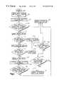
- FIG. 2is a flow diagram illustrating operation of the system of FIG. 1 in accordance with an embodiment of the present invention.
- FIG. 3is a flow diagram illustrating operation of the system of FIG. 1 in accordance with another embodiment of the present invention.
- FIG. 1illustrates a vehicle occupant protection system 10 for helping to protect a vehicle occupant located in an associated vehicle seat 12 . While the system 10 is illustrated as being associated with a front passenger-side seat 12 of a vehicle 14 , the present invention is equally applicable to helping protect an occupant of a driver-side seat or other passenger seats.
- the vehicle seat 12includes a seat back portion 16 and a seat cushion 18 and is connected to a vehicle floor 20 .
- the system 10includes a seat belt 22 .
- One end of the seat belt 22is secured to the vehicle 14 at a first location 24 in a known manner. It is also contemplated that the seat belt 22 may be secured to the vehicle seat 12 .
- the seat belt 22is extensible about a vehicle occupant 26 as is well known in the art.
- one end of the seat belt 22is releasably secured to a seat belt buckle assembly 28 using a tongue and buckle arrangement.
- the buckle assembly 28is secured to the vehicle 14 in a known manner. It is also contemplated that the seat belt buckle assembly 28 may be secured directly to the vehicle seat 12 .
- the seat belt buckle assembly 28includes a seat belt buckle switch, indicated at 30 , which is electrically connected to a controller 34 .
- the seat belt buckle switch 30provides a signal to the controller 34 having an electrical characteristic indicating whether the seat belt tongue and buckle are in a latched condition.
- a webbing or seat belt payout sensor 36also is electrically connected with the controller 34 .
- the payout sensor 36provides a signal to the controller 34 having an electrical characteristic indicative of the length of seat belt 22 that has been withdrawn from an associated seat belt retractor 38 .
- the length of seat belt 22 withdrawn from the retractor 38provides an indication of the occupant's girth, as well as an indication of whether an object other than a vehicle occupant has been strapped to the vehicle seat 12 .
- the system 10also includes an occupant weight sensor or scale 40 operatively associated with the lower seat cushion 18 .
- the weight sensor 40is formed, for example, of four individual weight sensors 42 , 44 , 46 , and 48 electrically connected with the controller 34 .
- the weight sensors 42 , 44 , 46 , and 48are located at the corners of the seat cushion 18 and may be mounted within the seat cushion 18 or connected between the seat cushion and the vehicle floor 20 .
- Each of the sensors 42 , 44 , 46 , and 48provides a respective signal to the controller 34 having an electrical characteristic indicative of the measured weight sensed by each sensor.
- the signals from the sensors 42 , 44 , 46 , and 48collectively provide an indication of a measured weight of an object located on the lower seat cushion 18 .
- the weight sensor 40is also configured to provide an indication of the location of the center of gravity of the vehicle occupant 12 relative to seat cushion 18 of the vehicle seat 12 . This is accomplished, for example, by the controller 34 comparing the weight measurements provided by each of the weight sensors 42 , 44 , 46 , and 48 in light of the known location of each sensor relative to the lower seat cushion 18 .
- the weight sensor 40could be formed of a lesser or greater number of individual weight sensors, such as fore and aft weight sensors or a grid array of weight sensors located in the seat cushion 18 , respectively.
- the present inventionalso contemplates that the weight sensor 40 could be formed of other types of sensors capable of detecting an occupant's center of gravity.
- pattern recognition technologiessuch as produced by IEE, which infer weight by measuring the print of an object on the vehicle seat, also could be used as the weight sensor 40 in accordance with the present invention.
- the system 10further includes an occupant position sensor 50 operative to sense the position of the occupant 26 located in the vehicle seat 12 .
- the sensor 50is electrically connected with the controller 34 and operative to provide a signal having an electrical characteristic indicative of the position of the vehicle occupant 26 .
- the occupant position sensor 50provides an indication of the relative distance between the vehicle occupant 26 and a portion of an occupant protection device 52 , such as the cover of an air bag module.
- the occupant position sensor 50preferably is an ultrasonic sensor, such as disclosed in U.S. Pat. No. 5,626,359 to Steffens, Jr. et al.
- the ultrasonic sensor 50is mounted in a dashboard, roof, or instrument panel 54 of the vehicle 14 adjacent to the occupant protection device 52 .
- the controller 34triggers the ultrasonic sensor 50 to produce an ultrasonic pulse 56 .
- the ultrasonic pulse 56strikes the occupant 26 , a reflected pulse is returned to the ultrasonic sensor 50 .
- the ultrasonic sensor 50provides a signal to the controller 34 .
- the controller 34determines the time between transmission of the ultrasonic pulse 56 and receipt of the reflected pulse and, from the time differential, calculates the distance between the ultrasonic sensor 50 and the occupant. Because the controller 34 “knows” the location of the cover of the air bag module relative to the ultrasonic sensor 50 , the distance between the vehicle occupant 26 and the cover of the air bag module is easily calculated using a predetermined formula or look-up table.
- an occupant position sensormight be located within the vehicle seat 12 and aimed towards the front of the vehicle 14 to detect the distance between the vehicle occupant 26 and the vehicle seat.
- a sensoralso could be mounted to the vehicle roof to detect the position of the vehicle occupant 26 relative to the occupant protection device 52 .
- a sensorcould be located in a vehicle door to measure the distance between the vehicle occupant 26 and the occupant protection device 52 .
- occupant position sensorsmay be used including, for example, a capacitive position sensor, such as disclosed in U.S. Pat. No. 5,722,686 to Blackburn et al., or an infrared position sensor, such as disclosed in U.S. Pat. No. 5,330,226 to Gentry et al.
- the occupant protection device 52preferably is an inflatable occupant protection restraint device which, when actuated, helps protect a vehicle occupant 26 during a vehicle crash event.
- the occupant protection device 52includes an air bag operatively mounted in a housing located in the instrument panel 54 of the vehicle 14 .
- the controller 34is electrically connected to the occupant protection device 52 , such as to a squib (not shown) for actuating an inflator to provide fluid for inflating the air bag.
- the controller 34Upon determining the occurrence of vehicle crash event, the controller 34 provides an actuation signal to the squib. This ignites the squib, which actuates the inflator to provide inflation fluid to inflate the air bag. Inflators with single or multiple levels also could be used.
- the system 10helps to detect such circumstances and disable or enable the occupant protection device 52 as is appropriate.
- the system 10includes an acceleration sensor 60 electrically connected to the controller 34 .
- the acceleration sensor 60is operative to provide an acceleration signal based on the sensed vehicle acceleration.
- the acceleration sensor 60is, for example, an accelerometer that provides a signal having an electrical characteristic indicative of vehicle acceleration.
- the acceleration sensor 60is operative to detect a level of vehicle acceleration of about 1 g and, more preferably, a level of about 0.7 g (g being the value of acceleration due to earth's gravity, i.e., 32 feet per second squared or 9.8 m/s 2 ).
- This level of accelerationtypically occurs during rapid vehicle deceleration, such as due to braking, or during evasive steering maneuvers. Such situations often indicate an increased likelihood of the occurrence of a vehicle crash event.
- this level of accelerationis below a level of acceleration indicative of a vehicle crash event that warrants actuation of the vehicle occupant protection device 52 by the controller 34 .
- the controller 34is able to determine the occurrence of both a vehicle crash event and an increased likelihood of a crash event based on the acceleration signal from the same sensor 60 .
- the acceleration sensor 60might be another type of acceleration sensing device, such as an electromechanical switch or a micromachined acceleration switch. These types of acceleration sensing devices have parts that move in response to being exposed to a level of vehicle acceleration above a predetermined threshold. Such an acceleration threshold should be set sufficiently low so as to detect rapid deceleration and evasive steering maneuvers.
- the system 10might include an optional crash event sensor, shown in dashed lines at 62 .
- the crash event sensor 62may be an acceleration sensor that is electrically connected to the controller 34 and provides an acceleration signal to the controller indicative of the sensed vehicle acceleration.
- at least one of the sensors 60is configured to have a sensitivity capable of detecting vehicle acceleration of about 0.7 g (e.g., a nominal sensitivity of about 4 g).
- the crash event sensor 62may be less sensitive, such as having a nominal sensitivity of about 100 g.
- the crash event sensor 62alternatively could be a crush zone sensor or other type of sensor that detects deformation of part of the vehicle 14 .
- the controller 34is, for example, a microcontroller or microcomputer programmed to control actuation of the vehicle occupant protection device 52 in response to the signals sampled from the various sensors 30 , 36 , 40 , 50 , and 60 (and 62 , if part of the system). In accordance with the present invention, the controller 34 determines whether to enable or disable actuation of the vehicle occupant protection device 52 based on a determined vehicle occupant characteristic. In an embodiment of the present invention having a multi-stage occupant protection device 52 , the controller 34 may limit the level of inflation provided by the multi-stage device based on the determined occupant characteristic.
- the determined occupant characteristicmay be an instantaneous sensed occupant condition or, alternatively, a dynamic occupant characteristic that varies over time.
- the controller 34actuates the vehicle occupant protection device upon determining the occurrence of a vehicle crash event, such as the sensor 60 sensing a level of vehicle acceleration indicative of a vehicle crash event in which deployment of the protection device is desirable.
- the controller 34preferably determines different occupant characteristics depending on the level of acceleration being experienced by the vehicle, as indicated by the acceleration signal from the acceleration sensor 60 .
- the controller 34determines that the acceleration signal indicates a level of acceleration below an acceleration threshold level, such as about 0.7 g, the controller operates in a static mode. In the static mode, the controller 34 determines an occupant characteristic based on the most recent sampling of at least two of the occupant condition sensors 30 , 40 , 50 , and 36 .
- the controller 34determines whether the vehicle occupant currently is in an out-of-position position relative to the protection device 52 , is so light as to be a child, or is belted or unbelted, and/or whether an excessive amount of seat belt webbing 22 has been withdrawn from the retractor 38 .
- Each of these determinations in the static moderesults in logic control of the occupant protection device 52 , i.e., either the protection device is enabled (ON) or enabled for low output curve (ON) enabled for a low output level (e.g., actuation of a single stage), or disabled (OFF).
- the controller 34determines that the acceleration sensor signal indicates a level of acceleration equal to or greater than the acceleration threshold level (e.g., about 0.7 g)
- the controlleroperates in a dynamic mode.
- the dynamic modetypically is active in situations when there is an increased likelihood of a vehicle crash event, such as during evasive steering maneuvers or deceleration due to braking.
- the controller 34analyzes each of the occupant conditions sensed by the occupant condition sensors 40 and 50 over a plurality of recent sampling intervals to determine how each of the sensed occupant conditions varies over time.
- the controller 34preferably analyzes a preselected plurality of the most recent samplings of the sensor signals from sensors 40 and 50 to determine whether the sampled signals indicate continuous movement to an OOP position, movement to a normal position, or sporadic movement back and forth. This determination may be based on comparing each set of sampled data signals with a corresponding set of stored data, which may be stored in a look-up table of the controller 34 .
- the controller 34will not disable the occupant protection device 52 while in the dynamic mode unless the sampled signals from both sensors 40 and 50 indicate movement of the occupant 26 to an OOP position.
- the controller 34determines that each sampled set of signals from the occupant condition sensors 40 and 50 indicates the occupant's position is changing from a normal position to an OOP position, the controller disables the vehicle occupant protection device 52 .
- the controller 34is configured to enable the vehicle occupant protection device 52 if both sets of signals from sensors 40 and 50 over time indicate that the occupant's position is rapidly changing from an OOP position to a normal position. In that situation, it would be desirable to actuate the vehicle occupant protection device upon detecting a vehicle crash event. Accordingly, the controller 34 operates in the dynamic mode to “predict” whether the signals sampled over time indicate that the occupant 26 is moving toward a normal position or toward an OOP position. The controller 34 disables the occupant protection device 52 only upon confirming occupant movement to an OOP position based on signals from sensors 40 and 50 . If the controller determines the occupant 26 is moving to a normal position or if the sampled sets of signals from sensors 40 and 50 are inconsistent, the occupant protection device 52 is enabled.
- the acceleration signals and corresponding thresholdsare described as being actual acceleration values, the acceleration signals may be processed using a variety of algorithms to provide signals functionally related to the sensed acceleration.
- the resulting signalsmay, in accordance with the present invention, be compared with appropriate threshold values to determine if the controller is in the dynamic mode, static mode as well as whether a vehicle crash event has occurred for which actuation of the protection device 52 is desired. Examples of suitable alternative acceleration-based control algorithms are disclosed in U.S. Pat. No. 5,935,182, U.S. Pat. No. 5,758,899 and U.S. Pat. No. 5,587,906.
- the operation processbegins at step 100 which occurs, for example, at power-up of the vehicle.
- step 100occurs, for example, at power-up of the vehicle.
- the internal states of the controller 34are initialized and appropriate flag conditions are set to their initial values, including entering the static mode described above.
- step 102the signals from the occupant condition sensors 40 and 50 are sampled.
- thisincludes sampling signals from the occupant position sensor 50 and the weight sensor 40 .
- the signalsare sampled at regular intervals and are stored in appropriate memory of the controller 34 .
- step 104the controller 34 determines a static occupant characteristic based on the occupant conditions currently being sensed, namely, the position and weight of the occupant 26 .
- the controllerpreferably also determines a location for the occupant's center of gravity based on the signals from weight sensors 42 , 44 , 46 , and 48 .
- the occupant's weight(or a weight of an object on the seat 12 ) may be determined based on compensated values of the signals from the sensors 42 , 44 , 46 , and 48 . This determination may be made using a predetermined formula or appropriate look-up tables stored in the controller 34 .
- a characteristic or value indicative of the occupant's position relative to part of the vehicle occupant protection device 52is determined based on the sampled signal from sensor 50 . This determination may be made using a predetermined formula or look-up tables.
- the sampled weight and position signalsare stored in appropriate memory of the controller 34 . Alternatively, or in addition to the sampled signals, the determined weight and position characteristics may be stored.
- the controller 34stores in memory a plurality of the most recent samplings of the sensed weight and position signals for the occupant 26 .
- the static occupant condition characteristicsare determined based the most recent sampling of the signals from occupant condition sensors 40 and 50 .
- step 106a determination is made whether the determined static occupant condition information is such that it would be desirable to actuate the occupant protection device 52 during a vehicle crash event. For the system of FIG. 1, this includes determining whether the vehicle occupant 26 is too close to the occupant protection device 52 . It also includes determining whether the weight of the vehicle occupant has a compensated weight value (e.g., less than about 30-40 kg) for which it would be undesirable to actuate the occupant protection device 52 upon the occurrence of a vehicle crash event.
- a compensated weight valuee.g., less than about 30-40 kg
- step 106determines whether the occupant is too close to the occupant protection device and/or too small. If either determination in step 106 is negative, thereby indicating that the occupant is too close to the occupant protection device and/or too small, the process proceeds to step 108 .
- step 108the occupant protection device 52 is disabled or turned off, such as by the controller 34 setting an appropriate flag condition in memory.
- the processproceeds to step 110 .
- step 110the controller 34 samples the buckle switch signal from the buckle switch sensor 30 to obtain an indication of whether the vehicle occupant 26 is in a belted or unbelted condition.
- the processproceeds to step 112 in which a determination is made whether the buckle switch signal indicates a belted vehicle occupant condition. In the event that the buckle switch signal indicates that the vehicle occupant 26 is belted, the process proceeds to step 114 . Because a belted vehicle occupant 26 is less likely to slide off the vehicle seat 12 into an OOP position than an unbelted vehicle occupant, the controller 34 remains in the static operating mode (step 114 ).
- step 116each of the determined static occupant characteristics is compared against associated threshold levels. Specifically, the controller 34 determines whether the most recent sample of the occupant position sensor signal from sensor 50 indicates an occupant position relative to the occupant protection device 52 that is less than a predetermined distance from the protection device. The controller 34 also determines whether the most recent sampling of the occupant weight signals from sensors 42 , 44 , 46 , and 48 indicates a weight value and/or a relative center of gravity position value below respective predetermined threshold values.
- step 108the process returns to step 108 .
- step 108the occupant protection device is disabled.
- step 118the controller 34 enables the occupant protection device 52 , such as by setting an appropriate flag condition.
- step 120the controller 34 samples the acceleration sensor signal from the acceleration sensor 60 .
- the acceleration signalmay provide an indication of the absolute vehicle acceleration or, alternatively, may provide an indication whether the vehicle acceleration is above or below a predetermined level of acceleration, such as about 0.7 g.
- step 122a determination is made whether the acceleration sensor signal from the acceleration sensor 60 indicates an acceleration greater than the acceleration threshold level.
- This acceleration threshold levelis selected to provide a threshold level of acceleration that is less than the level of acceleration required for actuation of the associated occupant protection device 52 , yet still indicate an increased likelihood of a vehicle crash event. As stated above, this may occur as a result of rapid deceleration by braking or during an evasive steering maneuver.
- step 114If the sensed acceleration from the sensor 60 is not determined to be greater than the acceleration threshold level, the process returns to step 114 and the controller 34 remains in the static mode. On the other hand, if the sensed acceleration is greater than the acceleration threshold level, the control process proceeds to step 124 in which the controller 34 enters the dynamic operating mode.
- the operation of the system 10has been described as a series of steps.
- the operation of the system 10equally could be expressed as a plurality of states or operating modes that change in response to the sensed conditions.
- the dynamic operating modepreferably is entered upon the acceleration signal from the sensor 60 indicating a vehicle acceleration above the predetermined acceleration threshold level, such as about 0.7 g.
- step 126the controller 34 determines a dynamic occupant characteristic based on a plurality of the most recent samplings of the stored sensor signals from the occupant condition sensors 40 and 50 .
- the controller 34characterizes how each of the sensed occupant conditions varies over time based on the stored signal samples from the sensors 40 and 50 . This characterization may include interpolating between adjacent sampled values to obtain a more continuous representation of each of the sensed occupant conditions.
- step 128the controller 34 analyzes the sensed occupant position based on a plurality of consecutive samples of the signal from the position sensor 50 to characterize how the occupant's position changes over the sampling time interval. The controller 34 then compares this characterization against stored occupant position information to determine whether the characterization indicates occupant movement to an OOP position.
- the controller 34analyzes the sensed occupant weight values from each of the weight sensors 42 , 44 , 46 , and 48 over a plurality of consecutive sampling intervals to characterize how the occupant's weight distribution on the seat cushion 18 changes over the sampling time interval. The controller 34 then compares this characterization against stored weight distribution information to determine whether the characterization indicates occupant movement to an OOP position.
- step 128determines that the weight distribution and occupant position characterizations either are inconsistent or both indicate movement to a normal position. If the controller 34 determines that the weight distribution and occupant position characterizations either are inconsistent or both indicate movement to a normal position, the controller enables the occupant protection device 52 (step 118 ), such as by setting the appropriate flag condition in memory.
- step 128the control process proceeds to step 108 .
- the occupant protection device 52is disabled, such as by the controller 34 setting an appropriate flag condition.
- the system 10 in accordance with the present inventionprovides protection against false detection of the occupant being in an OOP position. Specifically, making a position determination based on signals from both sensors 40 and 50 helps to eliminate a false OOP position determination.
- the system 10further helps eliminate erroneous actuation of an occupant protection device 52 for an underweight vehicle occupant having a weight at or near the imposed response limits of the system 10 .
- a detected weight for a child or other lightweight vehicle occupant having a weight at or near a fixed weight thresholdmight exceed the threshold during periods of increased vehicle acceleration.
- This increase in detected weightmay be due to acceleration forces and/or due to forces from the lap portion of a seat belt.
- Such an increase in the detected weightcould, in a conventional system, permit actuation of an associated occupant protection device.
- the system 10in accordance with the present invention, is able to detect such an increase in the detected weight based on the signals from the sensor 40 and determine the cause of such weight increase. This determination, based on detecting such changes in the occupant's weight during periods of increased acceleration, enables the system 10 to turn OFF the occupant protection device despite the increase in detected weight.
- FIG. 3The operation of the controller 34 , in accordance with an alternative embodiment of the present invention, is shown in FIG. 3 .
- identical reference numbersare used to refer to corresponding process steps previously described with respect to FIG. 2 .
- This embodimentis substantially identical to that described in FIG. 2, with the addition of the operation of the seat belt payout sensor 36 . Consequently, only the additional steps are described below.
- step 112 of FIG. 3if it is determined that the buckle switch signal from the buckle switch 30 indicates a belted vehicle occupant condition, the process proceeds to step 140 .
- the controller 34samples the seat belt payout sensor signal from the seat belt payout sensor 36 .
- step 142a determination is made whether the amount of payout indicated by the payout signal from the payout sensor 36 exceeds a payout threshold. If the sensed amount of payout exceeds the payout threshold and the sensed occupant weight is less than the weight threshold, the process returns to step 108 to disable the occupant protection device 52 .
- the seat belt payout sensor 36provides a signal having a value that exceeds the payout threshold value (e.g., indicating an over-extended seat belt 22 ) and a the weight threshold is not exceeded, something other than an adult vehicle occupant usually is strapped to the seat. Such circumstances typically do not warrant actuation of the occupant protection device 52 during a vehicle crash event. However, if the determination of step 142 is negative, thereby indicating that the payout threshold is not exceeded, the process proceeds to step 116 and the process continues as described above with respect to FIG. 2 .
- controller 34could be configured to control operation of one or both of the other sensors 40 , 50 , or such control may be shared by the controller and the sensors themselves.
- improvements, changes and modifications within the skill of the artare intended to be covered by the appended claims.
Landscapes
- Engineering & Computer Science (AREA)
- Mechanical Engineering (AREA)
- Physics & Mathematics (AREA)
- Electromagnetism (AREA)
- Air Bags (AREA)
Abstract
Description
Claims (18)
Priority Applications (2)
| Application Number | Priority Date | Filing Date | Title |
|---|---|---|---|
| US09/455,731US6282473B1 (en) | 1999-12-07 | 1999-12-07 | System and method for controlling a vehicle occupant protection device |
| DE10060649ADE10060649B4 (en) | 1999-12-07 | 2000-12-06 | System and method for controlling a vehicle occupant protection device |
Applications Claiming Priority (1)
| Application Number | Priority Date | Filing Date | Title |
|---|---|---|---|
| US09/455,731US6282473B1 (en) | 1999-12-07 | 1999-12-07 | System and method for controlling a vehicle occupant protection device |
Publications (1)
| Publication Number | Publication Date |
|---|---|
| US6282473B1true US6282473B1 (en) | 2001-08-28 |
Family
ID=23810066
Family Applications (1)
| Application Number | Title | Priority Date | Filing Date |
|---|---|---|---|
| US09/455,731Expired - LifetimeUS6282473B1 (en) | 1999-12-07 | 1999-12-07 | System and method for controlling a vehicle occupant protection device |
Country Status (2)
| Country | Link |
|---|---|
| US (1) | US6282473B1 (en) |
| DE (1) | DE10060649B4 (en) |
Cited By (38)
| Publication number | Priority date | Publication date | Assignee | Title |
|---|---|---|---|---|
| US6363308B1 (en)* | 2000-10-16 | 2002-03-26 | Delphi Technologies, Inc. | Satellite crash sensor and method with constant and dynamic thresholds for multi-stage restraint deployment |
| US6416080B1 (en)* | 2000-10-04 | 2002-07-09 | Trw Inc. | Apparatus and method for protecting a vehicle occupant utilizing a correlation between an occupant-associated center and a distance to an occupant-associated surface |
| US20020096868A1 (en)* | 2000-09-23 | 2002-07-25 | Wolfgang Drobny | Method for occupant classification in a motor vehicle |
| US20020129986A1 (en)* | 2001-03-16 | 2002-09-19 | Hiroshi Aoki | Occupant sensor |
| US6467804B2 (en)* | 1999-12-24 | 2002-10-22 | Aisin Seiki Kabushiki Kaisha | Vehicle seat |
| US6494284B1 (en)* | 2000-11-03 | 2002-12-17 | Trw Inc. | Seat arrangement for a vehicle having an actuatable occupant protection device |
| US6499763B1 (en)* | 1999-10-07 | 2002-12-31 | Takata Corporation | Passenger protection device |
| US20030075969A1 (en)* | 2001-09-21 | 2003-04-24 | Georg Fromme | Industrial truck with a safety belt |
| US20030083795A1 (en)* | 2001-10-31 | 2003-05-01 | Automotive Systems Laboratory, Inc. | Occupant detection system |
| US6626460B2 (en)* | 2000-06-14 | 2003-09-30 | Takata Corporation | Actuator control method |
| US6640175B2 (en)* | 2001-08-09 | 2003-10-28 | Trw Vehicle Safety Systems Inc. | Weight based occupant classification system for controlling enablement of a protection device |
| US20040016577A1 (en)* | 2000-09-29 | 2004-01-29 | Harald Lichtinger | Weight classification system |
| US20040032118A1 (en)* | 2002-04-18 | 2004-02-19 | Honda Giken Kogyo Kabushiki Kaisha | Process for controlling deployment of airbag |
| WO2004016476A1 (en)* | 2002-07-20 | 2004-02-26 | Robert Bosch Gmbh | Method and arrangement for the classification of objects occupying a seat |
| US6714132B2 (en) | 2001-10-11 | 2004-03-30 | The United States Of America As Represented By The Administrator Of The National Aeronautics And Space Administration | Self-activating system and method for alerting when an object or a person is left unattended |
| EP1426243A1 (en)* | 2002-12-05 | 2004-06-09 | Dr.Ing. h.c.F. Porsche Aktiengesellschaft | Seat foundation for a vehicle seat |
| US20040118178A1 (en)* | 2002-12-18 | 2004-06-24 | Mark Marentic | Machine for testing occupant restraint system |
| US20040135354A1 (en)* | 2002-10-31 | 2004-07-15 | Tsunenori Kishimoto | Occupant protection apparatus for vehicle |
| US20050056467A1 (en)* | 2003-09-15 | 2005-03-17 | Siemens Aktiengesellschaft | Devices and method for detecting the position and the weight of a person |
| WO2005025944A1 (en)* | 2003-09-15 | 2005-03-24 | Siemens Aktiengesellschaft | Devices and method for recognizing the position and weight of a person |
| US20050090959A1 (en)* | 2000-07-12 | 2005-04-28 | Siemens Automotive Corporation | Hardware independent mapping of multiple sensor configurations for classification of persons |
| US20050121236A1 (en)* | 2002-05-15 | 2005-06-09 | Sartorius Ag | Force measuring system having several force-measuring cells and a circuit calculating a total signal |
| WO2005092663A1 (en)* | 2004-03-29 | 2005-10-06 | Siemens Aktiengesellschaft | Method and device for determining a variable characteristic of a mass that rests on the seating area of a seat |
| WO2006005697A1 (en)* | 2004-07-12 | 2006-01-19 | Siemens Aktiengesellschaft | System for identifying occupancy of a vehicle seat |
| US20060028007A1 (en)* | 2003-02-05 | 2006-02-09 | Thomas Lehnst | Driver's seat with weight sensor |
| US20060244246A1 (en)* | 1992-05-05 | 2006-11-02 | Automotive Technologies International, Inc. | Airbag Deployment Control Based on Seat Parameters |
| US20070257474A1 (en)* | 2006-05-08 | 2007-11-08 | Trw Automotive Gmbh | Vehicle occupant safety system and method for detecting the position of a vehicle occupant |
| US20070282505A1 (en)* | 2006-02-03 | 2007-12-06 | Tk Holdings Inc. | System and method for seat belt control |
| US20090005214A1 (en)* | 2005-07-27 | 2009-01-01 | Eaton Corporation | Method for reducing torque required to crank engine in hybrid vehicle |
| US20090062989A1 (en)* | 2005-05-25 | 2009-03-05 | Aisin Seiki Kabushiki Kaisha | Seat device for vehicle |
| US20100114436A1 (en)* | 2008-11-06 | 2010-05-06 | Caterpillar Inc. | Operator restraint system |
| US20100268423A1 (en)* | 1995-06-07 | 2010-10-21 | Automotive Technologies International, Inc. | Occupant Protection Systems Control Techniques |
| CN103010152A (en)* | 2012-06-13 | 2013-04-03 | 浙江吉利汽车研究院有限公司杭州分公司 | Seat belt, seat belt use detection system and detection method |
| US20140330484A1 (en)* | 2011-10-10 | 2014-11-06 | Heiko Freienstein | Method for activating a safety actuator of a motor vehicle |
| JP2015128932A (en)* | 2014-01-07 | 2015-07-16 | 本田技研工業株式会社 | Passenger determination device and passenger determination method |
| US20150251618A1 (en)* | 2014-03-10 | 2015-09-10 | Ford Global Technologies, Llc | System and method for seatbelt use monitoring |
| US20240270192A1 (en)* | 2023-02-09 | 2024-08-15 | Audi Ag | Device for activating/deactivating an airbag function in a vehicle |
| US20250042355A1 (en)* | 2023-08-03 | 2025-02-06 | GM Global Technology Operations LLC | System and method for determining whether a seatbelt buckle extender is used in conjunction with a seatbelt |
Families Citing this family (3)
| Publication number | Priority date | Publication date | Assignee | Title |
|---|---|---|---|---|
| DE102007032714A1 (en)* | 2007-07-13 | 2009-01-15 | GM Global Technology Operations, Inc., Detroit | Safety arrangement with an airbag device and method for controlling the safety arrangement |
| DE102014117794B4 (en)* | 2014-12-03 | 2025-07-03 | Valeo Schalter Und Sensoren Gmbh | Device for detecting an object in the interior of a motor vehicle, motor vehicle and associated method |
| DE102022108701B4 (en) | 2022-04-11 | 2025-01-23 | Valeo Schalter Und Sensoren Gmbh | Device and method for determining a mass of an occupant of a vehicle |
Citations (10)
| Publication number | Priority date | Publication date | Assignee | Title |
|---|---|---|---|---|
| US5330226A (en) | 1992-12-04 | 1994-07-19 | Trw Vehicle Safety Systems Inc. | Method and apparatus for detecting an out of position occupant |
| US5626359A (en) | 1993-12-02 | 1997-05-06 | Trw Vehicle Safety Systems, Inc. | Method and apparatus for controlling an actuatable restraining device in response to discrete control zones |
| US5785347A (en)* | 1996-10-21 | 1998-07-28 | Siemens Automotive Corporation | Occupant sensing and crash behavior system |
| US5848802A (en)* | 1992-05-05 | 1998-12-15 | Automotive Technologies International, Inc. | Vehicle occupant position and velocity sensor |
| US5904368A (en)* | 1997-09-16 | 1999-05-18 | Trw Inc. | Occupant restraint system and control method with variable sensor rate and/or sample rate |
| US5947514A (en)* | 1998-02-20 | 1999-09-07 | Breed Automotive Technology, Inc. | Valve controlled automotive pyrotechnic systems |
| US5954775A (en) | 1997-02-05 | 1999-09-21 | Delco Electronics Corp. | Dual rate communication protocol |
| US6036225A (en)* | 1998-07-01 | 2000-03-14 | Trw Inc. | Method and apparatus for controlling an actuatable restraint device using crash severity indexing |
| US6094610A (en)* | 1998-03-30 | 2000-07-25 | Trw Vehicle Safety Systems Inc. | Characterizing a proximately located occupant body portion with a sensor matrix |
| US6116639A (en)* | 1994-05-09 | 2000-09-12 | Automotive Technologies International, Inc. | Vehicle interior identification and monitoring system |
Family Cites Families (10)
| Publication number | Priority date | Publication date | Assignee | Title |
|---|---|---|---|---|
| DE4005598C2 (en)* | 1990-02-22 | 2000-06-15 | Bosch Gmbh Robert | Protection procedure for vehicle occupants and device for carrying out the procedure |
| DE4023109A1 (en)* | 1990-07-20 | 1992-01-23 | Messerschmitt Boelkow Blohm | Releasing motor vehicle occupant protection appts. - sensing body positions w.r.t. to safety device e.g. inflatable cushion for more effective operation esp. for head and chest |
| JP2511217Y2 (en)* | 1990-09-20 | 1996-09-25 | 本田技研工業株式会社 | Occupant protection device |
| US5587906A (en)* | 1994-06-13 | 1996-12-24 | Trw Inc. | Method and apparatus for sensing a vehicle crash condition using velocity enhanced acceleration crash metrics |
| US5722686A (en)* | 1995-05-16 | 1998-03-03 | Trw Vehicle Safety Systems, Inc. | Method and apparatus for sensing an occupant position using capacitance sensing |
| US5758899A (en)* | 1995-06-15 | 1998-06-02 | Trw Inc. | Method and apparatus for providing a safing function for side impact crash sensing systems |
| DE19546297C2 (en)* | 1995-12-12 | 2003-12-04 | Temic Bayern Chem Airbag Gmbh | Airbag system with variable deployment time |
| DE19637108B4 (en)* | 1996-09-12 | 2005-10-27 | Adam Opel Ag | Occupant protection system for motor vehicles and a method for continuously monitoring the seating position of the occupant |
| US5935182A (en)* | 1996-09-24 | 1999-08-10 | Trw Inc. | Method and apparatus for discriminating a vehicle crash using virtual sensing |
| DE19754166A1 (en)* | 1997-12-06 | 1999-06-10 | Volkswagen Ag | Procedure for seat occupation-dependent control of safety systems in cars |
- 1999
- 1999-12-07USUS09/455,731patent/US6282473B1/ennot_activeExpired - Lifetime
- 2000
- 2000-12-06DEDE10060649Apatent/DE10060649B4/ennot_activeExpired - Fee Related
Patent Citations (10)
| Publication number | Priority date | Publication date | Assignee | Title |
|---|---|---|---|---|
| US5848802A (en)* | 1992-05-05 | 1998-12-15 | Automotive Technologies International, Inc. | Vehicle occupant position and velocity sensor |
| US5330226A (en) | 1992-12-04 | 1994-07-19 | Trw Vehicle Safety Systems Inc. | Method and apparatus for detecting an out of position occupant |
| US5626359A (en) | 1993-12-02 | 1997-05-06 | Trw Vehicle Safety Systems, Inc. | Method and apparatus for controlling an actuatable restraining device in response to discrete control zones |
| US6116639A (en)* | 1994-05-09 | 2000-09-12 | Automotive Technologies International, Inc. | Vehicle interior identification and monitoring system |
| US5785347A (en)* | 1996-10-21 | 1998-07-28 | Siemens Automotive Corporation | Occupant sensing and crash behavior system |
| US5954775A (en) | 1997-02-05 | 1999-09-21 | Delco Electronics Corp. | Dual rate communication protocol |
| US5904368A (en)* | 1997-09-16 | 1999-05-18 | Trw Inc. | Occupant restraint system and control method with variable sensor rate and/or sample rate |
| US5947514A (en)* | 1998-02-20 | 1999-09-07 | Breed Automotive Technology, Inc. | Valve controlled automotive pyrotechnic systems |
| US6094610A (en)* | 1998-03-30 | 2000-07-25 | Trw Vehicle Safety Systems Inc. | Characterizing a proximately located occupant body portion with a sensor matrix |
| US6036225A (en)* | 1998-07-01 | 2000-03-14 | Trw Inc. | Method and apparatus for controlling an actuatable restraint device using crash severity indexing |
Cited By (74)
| Publication number | Priority date | Publication date | Assignee | Title |
|---|---|---|---|---|
| US7401807B2 (en)* | 1992-05-05 | 2008-07-22 | Automotive Technologies International, Inc. | Airbag deployment control based on seat parameters |
| US20060244246A1 (en)* | 1992-05-05 | 2006-11-02 | Automotive Technologies International, Inc. | Airbag Deployment Control Based on Seat Parameters |
| US20100268423A1 (en)* | 1995-06-07 | 2010-10-21 | Automotive Technologies International, Inc. | Occupant Protection Systems Control Techniques |
| US8157047B2 (en) | 1995-06-07 | 2012-04-17 | Automotive Technologies International, Inc. | Occupant protection systems control techniques |
| US6499763B1 (en)* | 1999-10-07 | 2002-12-31 | Takata Corporation | Passenger protection device |
| US6467804B2 (en)* | 1999-12-24 | 2002-10-22 | Aisin Seiki Kabushiki Kaisha | Vehicle seat |
| US6626460B2 (en)* | 2000-06-14 | 2003-09-30 | Takata Corporation | Actuator control method |
| US20050090959A1 (en)* | 2000-07-12 | 2005-04-28 | Siemens Automotive Corporation | Hardware independent mapping of multiple sensor configurations for classification of persons |
| US7460938B2 (en)* | 2000-07-12 | 2008-12-02 | Continental Automotive Systems Us, Inc. | Hardware independent mapping of multiple sensor configurations for classification of persons |
| US20020096868A1 (en)* | 2000-09-23 | 2002-07-25 | Wolfgang Drobny | Method for occupant classification in a motor vehicle |
| US6808200B2 (en)* | 2000-09-23 | 2004-10-26 | Robert Bosch Gmbh | Method for occupant classification in a motor vehicle |
| US7503417B2 (en)* | 2000-09-29 | 2009-03-17 | Continental Automotive Systems Us, Inc. | Sensor assembly for seat occupant weight classification system |
| US20060124377A1 (en)* | 2000-09-29 | 2006-06-15 | Siemens Vdo Automotive Corporation | Weight classification system |
| US20040016577A1 (en)* | 2000-09-29 | 2004-01-29 | Harald Lichtinger | Weight classification system |
| US7048085B2 (en)* | 2000-09-29 | 2006-05-23 | Siemens Vdo Automotive Corporation | Weight classification system |
| US6416080B1 (en)* | 2000-10-04 | 2002-07-09 | Trw Inc. | Apparatus and method for protecting a vehicle occupant utilizing a correlation between an occupant-associated center and a distance to an occupant-associated surface |
| US6363308B1 (en)* | 2000-10-16 | 2002-03-26 | Delphi Technologies, Inc. | Satellite crash sensor and method with constant and dynamic thresholds for multi-stage restraint deployment |
| US6494284B1 (en)* | 2000-11-03 | 2002-12-17 | Trw Inc. | Seat arrangement for a vehicle having an actuatable occupant protection device |
| US6808201B2 (en)* | 2001-03-16 | 2004-10-26 | Takata Corporation | Occupant sensor |
| US20020129986A1 (en)* | 2001-03-16 | 2002-09-19 | Hiroshi Aoki | Occupant sensor |
| US6640175B2 (en)* | 2001-08-09 | 2003-10-28 | Trw Vehicle Safety Systems Inc. | Weight based occupant classification system for controlling enablement of a protection device |
| US20030075969A1 (en)* | 2001-09-21 | 2003-04-24 | Georg Fromme | Industrial truck with a safety belt |
| US20040160320A1 (en)* | 2001-10-11 | 2004-08-19 | Administrator Of The National Aeronautics And Space Administration | Self-activating system and method for alerting when an object or a person is left unattended |
| US7106203B2 (en) | 2001-10-11 | 2006-09-12 | The United States Of America As Represented By The Administrator Of The National Aeronautics And Space Administration | Self-activating system and method for alerting when an object or a person is left unattended |
| US6714132B2 (en) | 2001-10-11 | 2004-03-30 | The United States Of America As Represented By The Administrator Of The National Aeronautics And Space Administration | Self-activating system and method for alerting when an object or a person is left unattended |
| US20030083795A1 (en)* | 2001-10-31 | 2003-05-01 | Automotive Systems Laboratory, Inc. | Occupant detection system |
| US6921108B2 (en)* | 2002-04-18 | 2005-07-26 | Honda Giken Kogyo Kabushiki Kaisha | Process for controlling deployment of air bag |
| US20040032118A1 (en)* | 2002-04-18 | 2004-02-19 | Honda Giken Kogyo Kabushiki Kaisha | Process for controlling deployment of airbag |
| US20050121236A1 (en)* | 2002-05-15 | 2005-06-09 | Sartorius Ag | Force measuring system having several force-measuring cells and a circuit calculating a total signal |
| US7211748B2 (en)* | 2002-05-15 | 2007-05-01 | Sartorius Ag | Force measuring system having several force-measuring cells and a circuit calculating a total signal |
| US20050119812A1 (en)* | 2002-07-20 | 2005-06-02 | Reiner Marchthaler | Method and arrangement for the classification of objects occupying a seat |
| US7383113B2 (en) | 2002-07-20 | 2008-06-03 | Robert Bosch Gmbh | Method and system in the classification of objects occupying a seat |
| CN100413734C (en)* | 2002-07-20 | 2008-08-27 | 罗伯特-博希股份公司 | Method and arrangement for the classification of objects occupying a seat |
| WO2004016476A1 (en)* | 2002-07-20 | 2004-02-26 | Robert Bosch Gmbh | Method and arrangement for the classification of objects occupying a seat |
| US20040135354A1 (en)* | 2002-10-31 | 2004-07-15 | Tsunenori Kishimoto | Occupant protection apparatus for vehicle |
| EP1426243A1 (en)* | 2002-12-05 | 2004-06-09 | Dr.Ing. h.c.F. Porsche Aktiengesellschaft | Seat foundation for a vehicle seat |
| US20040164581A1 (en)* | 2002-12-05 | 2004-08-26 | Michael Mehrkens | Seat console for a vehicle seat |
| US7128181B2 (en) | 2002-12-05 | 2006-10-31 | Dr. Ing. H.C.F. Porsche Aktiengesellschaft | Seat console for a vehicle seat |
| US20040118178A1 (en)* | 2002-12-18 | 2004-06-24 | Mark Marentic | Machine for testing occupant restraint system |
| US6832503B2 (en) | 2002-12-18 | 2004-12-21 | Lear Corporation | Machine for testing occupant restraint system |
| US20060028007A1 (en)* | 2003-02-05 | 2006-02-09 | Thomas Lehnst | Driver's seat with weight sensor |
| US7315002B2 (en) | 2003-09-15 | 2008-01-01 | Siemens Aktiengesellschaft | Devices and method for detecting the position and the weight of a person |
| WO2005025944A1 (en)* | 2003-09-15 | 2005-03-24 | Siemens Aktiengesellschaft | Devices and method for recognizing the position and weight of a person |
| US20050056467A1 (en)* | 2003-09-15 | 2005-03-17 | Siemens Aktiengesellschaft | Devices and method for detecting the position and the weight of a person |
| WO2005092663A1 (en)* | 2004-03-29 | 2005-10-06 | Siemens Aktiengesellschaft | Method and device for determining a variable characteristic of a mass that rests on the seating area of a seat |
| WO2006005697A1 (en)* | 2004-07-12 | 2006-01-19 | Siemens Aktiengesellschaft | System for identifying occupancy of a vehicle seat |
| US20090062989A1 (en)* | 2005-05-25 | 2009-03-05 | Aisin Seiki Kabushiki Kaisha | Seat device for vehicle |
| US20090005214A1 (en)* | 2005-07-27 | 2009-01-01 | Eaton Corporation | Method for reducing torque required to crank engine in hybrid vehicle |
| US20110140504A1 (en)* | 2006-02-03 | 2011-06-16 | Tk Holdings, Inc. | System and method for seat belt control |
| US20110148176A1 (en)* | 2006-02-03 | 2011-06-23 | Tk Holdings Inc. | System and method for seat belt control |
| WO2007092307A3 (en)* | 2006-02-03 | 2008-01-10 | Tk Holdings Inc | A system and method for seat belt control |
| US7869921B2 (en) | 2006-02-03 | 2011-01-11 | Tk Holdings Inc. | System and method for seat belt control |
| EP2279918A3 (en)* | 2006-02-03 | 2011-06-15 | TK Holdings Inc. | A system and method for seat belt control |
| US20070282505A1 (en)* | 2006-02-03 | 2007-12-06 | Tk Holdings Inc. | System and method for seat belt control |
| US20110153165A1 (en)* | 2006-02-03 | 2011-06-23 | Tk Holdings Inc. | System and method for seat belt control |
| CN103950420A (en)* | 2006-02-03 | 2014-07-30 | Tk控股公司 | A system and method for seat belt control |
| CN103950420B (en)* | 2006-02-03 | 2017-01-04 | Tk控股公司 | The system and method controlled for seat belt |
| US8005597B2 (en) | 2006-02-03 | 2011-08-23 | Tk Holdings Inc. | System and method for seat belt control |
| US8019510B2 (en) | 2006-02-03 | 2011-09-13 | Tk Holdings Inc. | System and method for seat belt control |
| US20070257474A1 (en)* | 2006-05-08 | 2007-11-08 | Trw Automotive Gmbh | Vehicle occupant safety system and method for detecting the position of a vehicle occupant |
| US7997374B2 (en) | 2006-05-08 | 2011-08-16 | Trw Automotive Gmbh | Vehicle occupant safety system and method for detecting the position of a vehicle occupant |
| US8195365B2 (en) | 2008-11-06 | 2012-06-05 | Caterpillar Inc. | Operator restraint system |
| US20100114436A1 (en)* | 2008-11-06 | 2010-05-06 | Caterpillar Inc. | Operator restraint system |
| US9446685B2 (en)* | 2011-10-10 | 2016-09-20 | Robert Bosch Gmbh | Method for activating a safety actuator of a motor vehicle |
| US20140330484A1 (en)* | 2011-10-10 | 2014-11-06 | Heiko Freienstein | Method for activating a safety actuator of a motor vehicle |
| CN103010152B (en)* | 2012-06-13 | 2015-12-02 | 浙江吉利汽车研究院有限公司杭州分公司 | A kind of safety strap, safety strap use checking system and method for inspection |
| CN103010152A (en)* | 2012-06-13 | 2013-04-03 | 浙江吉利汽车研究院有限公司杭州分公司 | Seat belt, seat belt use detection system and detection method |
| JP2015128932A (en)* | 2014-01-07 | 2015-07-16 | 本田技研工業株式会社 | Passenger determination device and passenger determination method |
| US20150251618A1 (en)* | 2014-03-10 | 2015-09-10 | Ford Global Technologies, Llc | System and method for seatbelt use monitoring |
| US9676356B2 (en)* | 2014-03-10 | 2017-06-13 | Ford Global Technologies Llc | System and method for seatbelt use monitoring |
| US20240270192A1 (en)* | 2023-02-09 | 2024-08-15 | Audi Ag | Device for activating/deactivating an airbag function in a vehicle |
| US12304412B2 (en)* | 2023-02-09 | 2025-05-20 | Audi Ag | Device for activating/deactivating an airbag function in a vehicle |
| US20250042355A1 (en)* | 2023-08-03 | 2025-02-06 | GM Global Technology Operations LLC | System and method for determining whether a seatbelt buckle extender is used in conjunction with a seatbelt |
| US12275370B2 (en)* | 2023-08-03 | 2025-04-15 | GM Global Technology Operations LLC | System and method for determining whether a seatbelt buckle extender is used in conjunction with a seatbelt |
Also Published As
| Publication number | Publication date |
|---|---|
| DE10060649A1 (en) | 2001-08-16 |
| DE10060649B4 (en) | 2006-04-27 |
Similar Documents
| Publication | Publication Date | Title |
|---|---|---|
| US6282473B1 (en) | System and method for controlling a vehicle occupant protection device | |
| US6341252B1 (en) | Method and apparatus for controlling an actuatable occupant protection device | |
| US5454591A (en) | Method and apparatus for sensing a rearward facing child restraining seat | |
| EP0656283B1 (en) | Method and apparatus for controlling an actuatable restraining device in response to discrete control zones | |
| US5967548A (en) | Safety arrangement | |
| US5626359A (en) | Method and apparatus for controlling an actuatable restraining device in response to discrete control zones | |
| US6012007A (en) | Occupant detection method and apparatus for air bag system | |
| US6416080B1 (en) | Apparatus and method for protecting a vehicle occupant utilizing a correlation between an occupant-associated center and a distance to an occupant-associated surface | |
| AU623841B2 (en) | Passenger out-of-position sensor | |
| US5702123A (en) | Air bag apparatus for passenger seat | |
| US5746444A (en) | Method and apparatus for single point sensing of front and side impact crash conditions | |
| EP0987151B1 (en) | Control apparatus of safety device for crew | |
| EP0910524B1 (en) | Seat belt tension prediction system using an accelerometer mounted to the seat frame and a weight sensor | |
| US6553295B1 (en) | System for sensing a side impact collision | |
| EP1263627B1 (en) | Distributed electronic acceleration sensing for crash severity recognition | |
| JP2002513352A (en) | Passenger position sensing system | |
| US6371513B1 (en) | Side airbag apparatus | |
| EP1688316B1 (en) | Judgement method and apparatus for occupant detection and air bag control | |
| US20040182627A1 (en) | Vehicle impact sensor using both accelerometer and pressure sensing for side impact detection | |
| EP1026052B1 (en) | Activating control of a vehicle passenger restraint system | |
| KR100370808B1 (en) | Device for protecting occupants in an automobile and a method for controlling the inflation of a bag in an automobile | |
| EP1208021B1 (en) | Controller for occupant restraint system | |
| US20030025310A1 (en) | Air bag operation control system | |
| JPH0986336A (en) | Air bag device | |
| EP0847906B1 (en) | Passenger airbag actuation system |
Legal Events
| Date | Code | Title | Description |
|---|---|---|---|
| AS | Assignment | Owner name:TRW VEHICLE SAFETY SYSTEMS INC., OHIO Free format text:ASSIGNMENT OF ASSIGNORS INTEREST;ASSIGNOR:STEFFENS, JR., CHARLES E.;REEL/FRAME:010447/0830 Effective date:19991202 | |
| FEPP | Fee payment procedure | Free format text:PAYOR NUMBER ASSIGNED (ORIGINAL EVENT CODE: ASPN); ENTITY STATUS OF PATENT OWNER: LARGE ENTITY | |
| STCF | Information on status: patent grant | Free format text:PATENTED CASE | |
| AS | Assignment | Owner name:JPMORGAN CHASE BANK, NEW YORK Free format text:THE US GUARANTEE AND COLLATERAL AGREEMENT;ASSIGNOR:TRW VEHICLE SAFETY SYSTEMS, INC.;REEL/FRAME:013964/0290 Effective date:20030228 | |
| FPAY | Fee payment | Year of fee payment:4 | |
| FPAY | Fee payment | Year of fee payment:8 | |
| AS | Assignment | Owner name:JPMORGAN CHASE BANK, N.A., AS COLLATERAL AGENT, NE Free format text:SECURITY AGREEMENT;ASSIGNORS:TRW VEHICLE SAFETY SYSTEMS INC.;TRW AUTOMOTIVE U.S. LLC;KELSEY-HAYES COMPANY;REEL/FRAME:029529/0534 Effective date:20120928 | |
| FPAY | Fee payment | Year of fee payment:12 | |
| AS | Assignment | Owner name:TRW VEHICLE SAFETY SYSTEMS INC., MICHIGAN Free format text:RELEASE OF SECURITY INTEREST;ASSIGNOR:JPMORGAN CHASE BANK, N.A.;REEL/FRAME:031645/0697 Effective date:20131028 Owner name:TRW AUTOMOTIVE U.S. LLC, MICHIGAN Free format text:RELEASE OF SECURITY INTEREST;ASSIGNOR:JPMORGAN CHASE BANK, N.A.;REEL/FRAME:031645/0697 Effective date:20131028 Owner name:TRW INTELLECTUAL PROPERTY CORP., MICHIGAN Free format text:RELEASE OF SECURITY INTEREST;ASSIGNOR:JPMORGAN CHASE BANK, N.A.;REEL/FRAME:031645/0697 Effective date:20131028 Owner name:KELSEY-HAYES COMPANY, MICHIGAN Free format text:RELEASE OF SECURITY INTEREST;ASSIGNOR:JPMORGAN CHASE BANK, N.A.;REEL/FRAME:031645/0697 Effective date:20131028 |