US6282405B1 - Hybrid electricity and telecommunications distribution network - Google Patents
Hybrid electricity and telecommunications distribution networkDownload PDFInfo
- Publication number
- US6282405B1 US6282405B1US08/727,505US72750597AUS6282405B1US 6282405 B1US6282405 B1US 6282405B1US 72750597 AUS72750597 AUS 72750597AUS 6282405 B1US6282405 B1US 6282405B1
- Authority
- US
- United States
- Prior art keywords
- telecommunications
- network
- signal
- broadband
- buildings
- Prior art date
- Legal status (The legal status is an assumption and is not a legal conclusion. Google has not performed a legal analysis and makes no representation as to the accuracy of the status listed.)
- Expired - Lifetime
Links
Images


Classifications
- H—ELECTRICITY
- H04—ELECTRIC COMMUNICATION TECHNIQUE
- H04B—TRANSMISSION
- H04B3/00—Line transmission systems
- H04B3/54—Systems for transmission via power distribution lines
- H—ELECTRICITY
- H02—GENERATION; CONVERSION OR DISTRIBUTION OF ELECTRIC POWER
- H02J—CIRCUIT ARRANGEMENTS OR SYSTEMS FOR SUPPLYING OR DISTRIBUTING ELECTRIC POWER; SYSTEMS FOR STORING ELECTRIC ENERGY
- H02J13/00—Circuit arrangements for providing remote indication of network conditions, e.g. an instantaneous record of the open or closed condition of each circuitbreaker in the network; Circuit arrangements for providing remote control of switching means in a power distribution network, e.g. switching in and out of current consumers by using a pulse code signal carried by the network
- H02J13/00006—Circuit arrangements for providing remote indication of network conditions, e.g. an instantaneous record of the open or closed condition of each circuitbreaker in the network; Circuit arrangements for providing remote control of switching means in a power distribution network, e.g. switching in and out of current consumers by using a pulse code signal carried by the network characterised by information or instructions transport means between the monitoring, controlling or managing units and monitored, controlled or operated power network element or electrical equipment
- H02J13/00007—Circuit arrangements for providing remote indication of network conditions, e.g. an instantaneous record of the open or closed condition of each circuitbreaker in the network; Circuit arrangements for providing remote control of switching means in a power distribution network, e.g. switching in and out of current consumers by using a pulse code signal carried by the network characterised by information or instructions transport means between the monitoring, controlling or managing units and monitored, controlled or operated power network element or electrical equipment using the power network as support for the transmission
- H02J13/00009—Circuit arrangements for providing remote indication of network conditions, e.g. an instantaneous record of the open or closed condition of each circuitbreaker in the network; Circuit arrangements for providing remote control of switching means in a power distribution network, e.g. switching in and out of current consumers by using a pulse code signal carried by the network characterised by information or instructions transport means between the monitoring, controlling or managing units and monitored, controlled or operated power network element or electrical equipment using the power network as support for the transmission using pulsed signals
- H—ELECTRICITY
- H02—GENERATION; CONVERSION OR DISTRIBUTION OF ELECTRIC POWER
- H02J—CIRCUIT ARRANGEMENTS OR SYSTEMS FOR SUPPLYING OR DISTRIBUTING ELECTRIC POWER; SYSTEMS FOR STORING ELECTRIC ENERGY
- H02J13/00—Circuit arrangements for providing remote indication of network conditions, e.g. an instantaneous record of the open or closed condition of each circuitbreaker in the network; Circuit arrangements for providing remote control of switching means in a power distribution network, e.g. switching in and out of current consumers by using a pulse code signal carried by the network
- H02J13/00006—Circuit arrangements for providing remote indication of network conditions, e.g. an instantaneous record of the open or closed condition of each circuitbreaker in the network; Circuit arrangements for providing remote control of switching means in a power distribution network, e.g. switching in and out of current consumers by using a pulse code signal carried by the network characterised by information or instructions transport means between the monitoring, controlling or managing units and monitored, controlled or operated power network element or electrical equipment
- H02J13/00016—Circuit arrangements for providing remote indication of network conditions, e.g. an instantaneous record of the open or closed condition of each circuitbreaker in the network; Circuit arrangements for providing remote control of switching means in a power distribution network, e.g. switching in and out of current consumers by using a pulse code signal carried by the network characterised by information or instructions transport means between the monitoring, controlling or managing units and monitored, controlled or operated power network element or electrical equipment using a wired telecommunication network or a data transmission bus
- H02J13/00017—Circuit arrangements for providing remote indication of network conditions, e.g. an instantaneous record of the open or closed condition of each circuitbreaker in the network; Circuit arrangements for providing remote control of switching means in a power distribution network, e.g. switching in and out of current consumers by using a pulse code signal carried by the network characterised by information or instructions transport means between the monitoring, controlling or managing units and monitored, controlled or operated power network element or electrical equipment using a wired telecommunication network or a data transmission bus using optical fiber
- H—ELECTRICITY
- H04—ELECTRIC COMMUNICATION TECHNIQUE
- H04B—TRANSMISSION
- H04B3/00—Line transmission systems
- H04B3/54—Systems for transmission via power distribution lines
- H04B3/56—Circuits for coupling, blocking, or by-passing of signals
- H—ELECTRICITY
- H04—ELECTRIC COMMUNICATION TECHNIQUE
- H04B—TRANSMISSION
- H04B2203/00—Indexing scheme relating to line transmission systems
- H04B2203/54—Aspects of powerline communications not already covered by H04B3/54 and its subgroups
- H04B2203/5462—Systems for power line communications
- H04B2203/5466—Systems for power line communications using three phases conductors
Definitions
- This inventionrelates to a method of signal injection, transmission, interconnection (termination), and detection, and to a power transmission network, ie. a mains electricity distribution and/or transmission network, and a filter therefor.
- a power transmission networkie. a mains electricity distribution and/or transmission network, and a filter therefor.
- mains electricity networks and/or lines for telecommunications transmissione.g. voice, data, image and/or video
- the carrier frequencymay preferably be between 1-10 MHZ, and on, e.g., an 11 kV network maybe between e.g. 1-20 MHZ or possibly 5-60 MHZ. Signals of this frequency can be transmitted over large distances (using repeater stations if necessary) and therefore a network used in this way is suitable for general telecommunications and telephony signals.
- broadband telecommunications signalssuch as television communications
- broadband telecommunications signalsgenerally require a higher carrier frequency (or frequencies) and bandwidth.
- signalsare therefore usually transmitted on an independent broadband telecommunications network e.g. co-axial cable, optical fibre etc.
- a carrier frequency of up to hundreds of MHZmay be used on a network as described in PCT/GB93/02163, although the distance over which a signal with a particularly high carrier frequency may be transmitted is limited by the dynamic range sensitivities and power levels deployed on the network—possibly to around 7-40 metres on a typical UK network.
- the present inventionaims to provide a transmission network which alleviates some or all of the above problems.
- the present inventionprovides a network linking a plurality of premises comprising a section of broadband telecommunications network and a plurality of electrical power cables each connected to a respective one of the premises for supplying mains electrical power thereto, each of said power cables also being connected to the section of broadband telecommunications network so that telecommunications signals are transmissible between the section of broadband telecommunications network and each of said power cables, wherein a telecommunications signal is transmissible to and/or from said plurality of premises by being transmitted along the section of broadband telecommunications network and also along the respective power cable of each of said premises.
- the independent (preferably external) telecommunications networkcan be used to propagate the telecommunications signal over a long distance, with the (preferably external) power transmission/distribution network being used to propagate the telecommunications signal from the telecommunications network into e.g. the premises of a user and vice versa i.e. the communications may be bi-directional.
- the signal transmission networki.e. power network and/or telecommunications network is external to any building or premises such as an office or house. Inside such buildings, transmission distances are typically short and therefore attenuation losses relatively unimportant.
- the broadband telecommunications networkmay be a standard broadband distribution network e.g. a coaxial, twisted pair or fibre cable.
- a standard broadband distribution networke.g. a coaxial, twisted pair or fibre cable.
- Such telecommunications networksare currently available in most major countries. However, typically, the greatest cost and inconvenience associated with such telecommunications networks is not the initial installation of the main network but the connection of the main network to the premises of users.
- the present inventionallows the existing power distribution networks (which commonly feed into most suitable premises) to be used to connect the existing telecommunications network to the desired premises. Thus the additional cost and inconvenience of installing further standard telecommunications network is avoided.
- broadband telecommunications signalsmay be transmitted over the power transmission/distribution network without attenuation losses having any significant effect.
- the present inventionfurther includes satellite receiving means for receiving telecommunications signals from a satellite transmitter, wherein a telecommunications signal is transmissible from said satellite transmitter to said plurality of premises via said satellite receiving means, said section of broadband telecommunications network and said power cables.
- satellite receiving meansmay be replaced or supplemented by other telecommunications signal receiving means, such as a TV aerial, telephone connection, data connection, etc.
- the networkincludes a plurality of interface units, each of said interface units connecting one of said power cables to said section of broadband telecommunications network, each of said interface units including high pass filter means for allowing high frequency telecommunications signals to pass between said section of broadband telecommunications network and said power cable, and for preventing low frequency mains electrical power signals from passing therebetween.
- the present inventionprovides a method of transmitting a telecommunications signal between a pair of buildings, including the steps of transmitting the signal from a first building along an external power cable for supplying mains power to the first building, followed by transmitting the signal along a section of broadband telecommunications network, followed by transmitting the signal along a second external power cable for supplying mains electrical power to the second building.
- the telecommunications signalhas a carrier frequency greater than approximately 1 MHz.
- the carrier frequencymay in fact be less than 1 MHz ie. 800 kHz or even as low as 600 kHz, but as it is reduced so is the bandwidth.
- carrier frequencyrefers to the unmodulated frequency or frequencies of the carrier signal(s), and not to the frequency of the telecommunications signal or signals once modulated.
- a plurality of telecommunications signalsmay be provided, each having different carrier frequencies.
- the power networkmay include one or more phases, and may be a polyphase network including e.g. any one or more of 2, 3, 4, 6, 7 etc phases. Different sections of the network may include different numbers of phases.
- the power networkis a single phase network e.g. consisting of one or more single phase cable(s) connecting one or more customers building(s) or premises to a main polyphase (e.g. 3 phase) portion of the electricity distribution network.
- a single phase networke.g. consisting of one or more single phase cable(s) connecting one or more customers building(s) or premises to a main polyphase (e.g. 3 phase) portion of the electricity distribution network.
- the broadband telecommunications signalsare taken e.g. via a tap, from the main broadband distribution network (e.g. coaxial or fibre cable) via a suitable interface unit and fed into the customer's single phase cable via a suitable conditioning unit.
- the signalmay be amplified if necessary.
- the power networkis unbalanced i.e. provides unbalanced transmission characteristics.
- the cable(s) of the power networkmay be screened or clad e.g. with a suitable metal material, which enables the cable to behave as a pseudo-coaxial element to provide an unbalanced transmission network at the transmission frequency of the present invention.
- the power networkis a major (e.g. overground and/or underground) power network including e.g. any or all of 132 kV, 33 kV, 11 kV, 415 v and 240 v sections.
- the voice and data signalsmay be transmitted over any or all of the sections of the power network by suitable detection, amplification and/or regeneration and reintroduction as and when necessary.
- full duplex facilitiesare provided i.e. signals may be transmitted and/or received in all directions simultaneously.
- a network according to the present inventionmay be used for many speech and/or data transmission purposes, such as remote reading of electricity meters, remote banking and shopping, energy management systems, telephony (voice), switched telephony, security systems and/or interactive data services, multimedia services and television.
- speech and/or data transmission purposessuch as remote reading of electricity meters, remote banking and shopping, energy management systems, telephony (voice), switched telephony, security systems and/or interactive data services, multimedia services and television.
- the present inventionalso provides a communications apparatus (known hereinafter as a “network conditioning unit”) for use with a network according to the above aspects of the present invention.
- the network conditioning unitincludes a low pass filter portion or portions for filtering out the low frequency high amplitude mains power signal i.e. separating it from the telecommunications signal(s) and allowing it to pass through the conditioning unit.
- the unitalso includes a high pass coupling element for input and removal of telecommunications signals from the network and, preferably, a terminating element of similar impedance to the characteristic impedance of the network at that point.
- Such a unitensures that the high frequency telecommunications signals do not contaminate the internal low voltage wiring present inside a premises, and/or that noise sources from the internal low voltage premises wiring do not contaminate or corrupt the high frequency telecommunications signals being transmitted over the external electricity transmission and/or distribution network.
- variable electrical loading effectsi.e. the load impedances
- electrical energyi.e. the electrical loads
- an electrical filteris used at the interface between the external distribution network and the internal network of the premises, e.g. a house, of a user to ensure that the two signals are separated.
- a filtershould have minimal effect on the normal domestic electricity supply.
- the filter element of the present inventionwhich aims to reduce telecommunications signals entering the internal network of a users premises, preferably has no more than 1 volt dropped across it whilst supplying a 100 amp load from a 240 v, 50 HZ, single phase source.
- the network conditioning unitprovides impedance matching between reception/transmission devices and the power network. Additionally the network conditioning unit may carry full load or fault current at power frequencies whilst still carrying the voice and data signals.
- the present inventionprovides a method of signal transmission using a network as described herein.
- the signal propagationmay be between any or all of the phases and ground.
- the signalis injected between only one of the phases and ground, which also provides unbalanced transmission characteristics and the cable behaves as a pseudo coaxial transmission line.
- Single phase cablesmay typically be either concentric or split-concentric.
- meanssuch as a capacitive coupling between the parts of the split-concentric sheath
- the cablebehaves as a standard concentric cable.
- a wide range of different transmission techniquesare available for use with electricity power line communication each using various modulation methods including amplitude, frequency, phase; single, double and vestigal sideband, pulse position , width and amplitude; frequency shift keying (FSK), Gaussian filtered FSK (GFSK), Gaussian minimum shift keying (GMSK), Quaternary phase shift keying (QPSK), Orthogonal quaternary phase shift keying (OQPSK), Quadrature amplitude modulation (QAM), Pi/4 QPSK etc, together with various multiplexing, duplexing and multiple access techniques including frequency (FDM) (FDD), time (TDM) (TDD), code division (CDM) (CDMA) etc.
- FDMfrequency
- TDMtime
- CDMAcode division
- a large number of standard cordless telephone communication techniquesmay be suitable for effecting signal transmission over a conditioned network.
- Suitable standardsmay be CTO, CT 1 and CT 2 , AMPS, DECT (Digital European Cordless Telephone Standard), IS-54, IS-95, GSM, Q-CDMA, R-CDMA, UD-PCS, PHS, PACS, TACS, ENTACS, NMT450, NMT500, C-450, RTMS, Radicom 2000, NTJ, JTACS & NTACS, DCS 1800 etc.
- the network conditioning unitpreferably includes a low pass filter comprising a main inductor arranged between a mains electricity input and a mains electricity output and connected at each end thereof to a signal input/output line which is arranged in parallel to the mains electricity input and mains electricity output, the two connections including a first capacitor and a second capacitor each of a predetermined capacitance depending upon the portion of the frequency spectrum which is to be utilised for communications purposes.
- a low pass filtercomprising a main inductor arranged between a mains electricity input and a mains electricity output and connected at each end thereof to a signal input/output line which is arranged in parallel to the mains electricity input and mains electricity output, the two connections including a first capacitor and a second capacitor each of a predetermined capacitance depending upon the portion of the frequency spectrum which is to be utilised for communications purposes.
- the main inductoris operative to prevent communications signals from the signal input/output line from entering the domestic/industrial premises.
- This inductoris therefore preferably of a high inductance such as 10 ⁇ H to 200 ⁇ H for frequencies of 1 MHz and above.
- the first capacitor which connects the mains electricity input and the signal input/output lineacts as a coupling capacitor to allow communication signals through from the signal input/output line. whilst attenuating all low frequency components at or about the main electricity supply frequency (ie., 50/60 Hz).
- the second capacitor arranged between the mains electricity output and the signal input/output lineprovides a further attenuation of communication signals and is connected via the signal input/output line to ground.
- each such capacitoris preferably provided with a respective fuse arranged between the first or second capacitor and the signal's input/output line.
- a second inductorarranged between the connections between the signal input/output line and the first and second capacitors. This inductor has no effect on communication frequency signals but will provide a path to ground if the first capacitor develops a fault thereby allowing the first fuse to blow without allowing the power frequency signal onto the signal input/output line.
- the inductance of the main inductordepends upon the material of which it is made and the cross-section of the wire wound around the core.
- the 10 ⁇ H inductance previously specifiedis preferably a minimum and with use of better core material a higher inductance, for example of the order of 200 ⁇ H, can be obtained.
- a number of inductors connected in seriescould be used.
- the coupling capacitorhas a capacitance preferably in the range 0.01 to 0.50 ⁇ F and the second capacitor linking the mains electricity output with the signal input/output line and ground has a capacitance preferably in the range of 0.001 to 0.50 ⁇ F.
- the second inductor arranged on the signal input/output linepreferably has a minimum inductance of approximately 250 ⁇ H. This inductor therefore has no effect on communication frequency signals on the signal input/output line.
- the conductor used to construct the 250 ⁇ H inductorshould be of sufficient cross-sectioned area to take fault current should the decoupling capacitor fail to short circuit condition.
- any spurious self resonance in the inductive or capacitive elementsare avoided.
- the minimum values of inductance and capacitancemay be proportionally reduced.
- the filteris assembled in a screened box so as to provide a good earth and prevent radiation of the communication signals.
- the present inventionprovides a signal transmission network including at least one telecommunications network portion and at least one power transmission and/or distribution network portion.
- the present inventionprovides an power transmission and/or distribution network including input means for the input of a telecommunications signal onto the power transmission network, (e.g. an electricity transmission and/or distribution network) from a telecommunications network, and output means for removal of a similar telecommunications signal from the power network.
- a telecommunications signalonto the power transmission network, (e.g. an electricity transmission and/or distribution network) from a telecommunications network, and output means for removal of a similar telecommunications signal from the power network.
- the present inventionprovides an electricity distribution and/or power transmission network having a number of phases, said number being chosen from the list 1,2,4,5,6,7,8,9, . . . n (where n is an integer greater than 9), but preferably having 1 or 2 phases, and including input means for the input of a telecommunications signal having a carrier frequency greater than approximately 1 MHz onto at least one of the phase conductors of the network and output means for removing said telecommunications signal from at least one other phase conductor of the network.
- the present inventionprovides an unbalanced electricity distribution and/or power transmission network at least a part of which comprises a clad cable, the network including input means for the input onto the network of a telecommunications signal having a carrier frequency greater than approximately 1 MHz and output means for removing said telecommunications signal from the network, said signal being transmissible along said part of the network having clad cable.
- the present inventionprovides a trunk and branch multipoint electricity distribution and/or power transmission network including input means for the input onto the network of a telecommunications signal having a carrier frequency greater than approximately 1 MHz and output means for removing said telecommunications signal from the network.
- the present inventionprovides an electricity distribution and/or power transmission network at least part of which is external to a building, the network including input means for the input onto the network of a telecommunications signal having a carrier frequency greater than approximately 1 MHz and output means for removing said telecommunications signal from the network, said signal being transmissible along said external part of the network.
- the present inventionprovides a method of signal transmission including input of a telecommunications signal having a carrier frequency of greater than approximately 1 MHz onto at least one phase conductor of an electricity power distribution and/or transmission network, and subsequent reception of the signal from at least one other phase conductor of the network, said network having a number of phases, said number being chosen from the list 1,2,4,5,6,7,8,9, . . . n (where n is an integer greater than 9), but preferably having 1 or 2 phases.
- FIG. 1is a schematic diagram of a part of a network according to aspects of the present invention.
- FIG. 2is a schematic diagram of a first transmission system for a network shown in FIG. 1;
- FIG. 3is a schematic diagram of a second transmission system for a network shown in FIG. 1;
- FIG. 4is a schematic diagram of a third transmission system for a network shown in FIG. 1;
- FIG. 5Ais a cross section through a typical three phase cable
- FIG. 5Bis a section through a typical coaxial cable
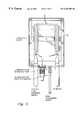
- FIG. 6is a preferred embodiment of a network conditioning unit used in the present invention.
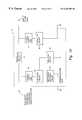
- FIG. 7is a second embodiment of a network conditioning unit used in the present invention.
- FIG. 8is a plan view of a network conditioning unit
- FIG. 9is a view of a circuit board for the network conditioning unit of FIG. 8 .
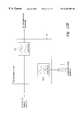
- FIG. 10is a schematic diagram of a network conditioning unit as used in present invention.
- FIGS. 11 a and 11 bare second and third schematic diagrams of a network conditioning unit as used in the present invention.
- FIGS. 12A, 12 B and 12 Cshow sectional views through a concentric, split-concentric and pseudo-concentric cable respectively.
- FIG. 13shows a hybrid network according to an aspect of the present invention.
- FIG. 1shows generally a network 40 .
- Mains electricityenters the network from an 11 kV transmission line 42 , via a transformer 44 and onto a 415 v three phase network 46 .
- the 415 v three phase networkis supplied to a number of locations, such as buildings 48 . Each of these buildings may receive only a single phase electricity supply or alternatively may receive a three phase power supply.
- Voice and data signalsmay be injected into the network (or alternatively received from the network) to/from a telecommunications network (e.g. co-axial, fibre or twisted pair cable), or a further part of the electricity distribution/transmission network, at an injection point 50 , to be transmitted and/or received by users in the premises 48 .
- a telecommunications networke.g. co-axial, fibre or twisted pair cable
- These signalsmay be narrow bandwidth e.g. telephony signals, or broadband e.g. television signals, as desired—depending on the attenuation and distance to be travelled along the power distribution network.
- each signal source and/or destinationis provided with a network conditioning unit 52 —shown in more detail in figure 11 a.
- This network conditioning unitincludes a low pass filter for separating out the two signals.
- a further (high current) conditioning unit 51may be fitted between the electricity and distribution transformer 44 and the injection point 50 in order to further remove transformer noise from the condition network 40 .
- the unit 51is fitted with a high current inductor.
- FIG. 13illustrates a portion of a hybrid signal transmission network according to the present invention.
- a part of a cable 130 of a broadband telecommunications networke.g. a coaxial, fibre or twisted pair cable
- the electricity distribution network 132may also carry telecommunications signals of suitable carrier frequency and bandwidth, as described elsewhere in this specification and that of PCT/GB93/02163.
- the telecommunications network 130carries broadband telecommunications signals e.g. television signals.
- the telecommunications signalse.g. television signals, which may be analogue and/or digital format, are input (or removed) from the telecommunications network 130 onto (or from) a portion 134 of the external electricity distribution network 132 via a conditioning unit 136 .
- the conditioning unit 136allows the telecommunications signals to be input onto (or removed from) the electricity cable 134 without either the telecommunications signals entering the electricity distribution network 132 or the electricity signals entering the telecommunications network 130 .
- telecommunications signalsmay be input onto the telecom network from the portion 134 of the electricity distribution network 132 .
- a coaxial/fibre interface unit 138 and an amplifier 140may be used to interface between the telecommunications network 130 and the conditioning unit 136 .
- the amplifier 140may be bi-directional (as shown) or uni-directional (in either direction, as required).
- the portion 134 of the external electricity distribution network 132is a single phase cable.
- Thismay be a concentric single phase cable or a split-concentric single phase cable set up to act as a pseudo-concentric cable as described with reference to FIGS. 12A, 12 B and 12 C.
- this single phase cableconnects a users premises 142 to the e.g. 3 phase electricity distribution network 132 .
- a second conditioning unit 144which separates the telecommunications signals 146 from the electricity supply 148 .
- a second conditioning unit 144which separates the telecommunications signals 146 from the electricity supply 148 .
- a plurality of such linksmay be made from the telecommunications network 130 to a corresponding plurality of users premises.
- the telecommunications network 130may be connected directly to the broadband telecommunications signal(s) transmitter, or alternatively may be connected via a radio or satellite link 150 .
- the conditioning unit(s) 136may be sited e.g. at street level, such as in a curb-side pillar or vault and adjacent to the electricity service position within the customers premises.
- the conditioning unit(s) 142may be sited, for example, near the customers premises or within the customers premises such as inside a HRC cut-out unit and/or the electricity meter.
- FIG. 2shows a portion of a three phase network 40 into which and from which data signals may be transmitted and received using the network conditioning units 52 .
- the cable of the networkis clad i.e. is surrounded by a sheath 41 e.g. along all or substantially all of its length.
- data signalscould be transmitted onto the yellow phase of the network by network conditioning unit 52 A i.e., the signal is applied between the yellow phase and earth as shown.
- the transmitted datamay then be received by any or all of conditioning units 52 B, 52 C and 52 D which are connected to the yellow, red and blue phases respectively.
- transmitted datamay be picked up on any phase of the cable, including the phases onto which the signals were not injected by the transmitting unit. This is due to the mutual capacitance between the phase conductors producing an effectively pseudo-coaxial nature of the three phase cable.
- datacan be transmitted and received by each unit.
- Each phase of the network 40is shown to include a transformer 43 .
- thisis effected by a single three phase transformer for all three phases, and not by three separate single phase transformers—although the latter may be possible.
- FIG. 3shows a portion of a three phase power network 40 into which and from which data signals may be transmitted and received using four network conditioning units 52 . As shown, the data signals are transmitted across two phases of the three phase network—in this case the red and blue phases.
- the non-used phase(s)may be terminated to provide an appropriate impedance. This may be done using an “L” circuit i.e. a series inductor with a shunter capacitor on the transformer side. This provides an optimum impedance and ensures that an RF signal which is coupled between e.g. the red and yellow phases, is not shunted down by a low impedance transformer connection. This is particularly useful if there is insufficient inductive reactance at e.g. the yellow phase transformer connection point.
- FIG. 4an alternative transmission system to FIG. 2 is shown, in which the data signals are transmitted across all three phases, i.e. blue, red and yellow, of the three phase network 40 .
- FIG. 5Ashows a simplified cross section of a three phase power cable 54 , including red phase 56 , yellow phase 58 , and blue phase 60 .
- Data signalsare transmitted between blue phase 60 and earth 62 , and are injected into the network via network conditioning unit 52 .
- the mutual capacitance between the phaseseffectively produces a short circuit. Therefore, such a transmission system gives a pseudo-coaxial characteristic, roughly equivalent to the coaxial cable shown in FIG. 5 B.
- the mutual capacitance between any two of the phases in the three phase cableis shown schematically as 64 in FIG. 5 A—similar mutual capacitance exists between other parts of phases.
- FIGS. 11 a and 11 bshow conditioning units as designated 52 and 51 in FIG. 1 respectively.
- the conditioning unitcan be considered to be equivalent to a low pass filter 100 and a coupling capacitor element 102 (which can be considered to be a high pass filer element).
- the low pass filter element 100allows mains power to be supplied from the distribution network to a consumer whilst preventing high frequency communication signals from entering the consumers premises.
- a coupling capacitor, or high pass filter element, 102is provided to couple the high frequency communication signals onto the distribution network whilst preventing the mains power from entering the communications apparatus.
- the conditioning unit componentsmay be fitted into e.g. an electricity meter case located in a consumer's premises, or possibly may be set into a compartment at the rear of such a meter. Alternatively the necessary components may be located in e.g. a customer's high rupturing capacity (HRC) fuse or cut-out unit.
- HRChigh rupturing capacity
- an embodiment of a conditioning unit(essentially a filter) according to an aspect of the invention is indicated generally by the reference numeral 10 and is connected between a mains electricity input 12 and a mains electricity output 14 .
- a signal input/output line 16is also connected into the filter.
- the mains power lineis a standard 50 Hz mains electricity power supply providing a domestic electricity power source of 240 v at a maximum current of 100 amps for normal usage.
- the filter 10is assembled into a metal box which prevents radiation of the communication signals to externally located appliances and which provides a connection 18 to earth for the signal input/output line 16 .
- the filter 10includes a first or main inductor 20 formed of 16 mm 2 wire wound on a 10 mm diameter, 200 mm long ferrite rod with 30 turns of wire therearound. This provides an inductance of approximately 50 ⁇ H. This may be a minimum for the signal characteristics utilised. The use of better materials or a plurality of series inductors would increase the inductance of the inductor up to, for example, approximately 200 ⁇ H.
- a first connection 22 between the mains electricity input 12 and signal input/output line 16comprises a first or coupling capacitor 24 having a capacitance of between 0.01 and 0.50 ⁇ F, and preferably around 0.1 ⁇ F.
- This coupling capacitor 24is connected to a first fuse 26 which is arranged to blow in the event of failure or a fault developing in capacitor 24 .
- a second connection 28includes a second capacitor 30 having a capacitance of between 0.001 and 0.50 ⁇ F, preferably around 0.1 ⁇ F. This capacitor provides further attenuation of the communication signals by shorting to the earth or ground 18 .
- a second fuse 32is provided to blow if a fault develops in the second capacitor 30 thereby preventing further unit damage.
- the signal input/output line 16is connected to includes a second inductor 34 having an inductance of approximately 250 ⁇ H minimum.
- This inductoris provided as a damage limiter in the event of failure of the coupling capacitor 24 . In the event of such failure this inductor provides a path to the ground 18 for the 50 Hz mains electricity power frequency thereby blowing fuse 26 .
- the inductorhas no effect on the communication frequency signals present on the signal input/output line 16 .
- FIG. 7shows a second embodiment of a filter according to an aspect of the present invention.
- the filter 70includes a pair of inductors L 1 , L 2 arranged in series between a mains electricity input 72 and a mains electricity output 74 .
- a preferred value for L 1 and L 2is approximately 16 ⁇ H.
- Connected between the RF input line 80 and the mains input 72is a first fuse F 1 and capacitor C 1 , and connected between the RF input 80 and ground is a third inductor L 3 , which acts as an RF choke and has a typical value of 250 ⁇ H.
- Typical value for the capacitorsis around 0.1 ⁇ F and for the fuses approximately 5 amps HRC (high rupturing capacity).
- FIG. 8a typical housing arrangement for a network conditioning unit according to an embodiment of the present invention is shown.
- the main inductors L 1 and L 2are housed within a shielding box 90 .
- Various connectionsare shown, including a communication interface port 92 to which a user's communication equipment would normally be connected. However, as shown in FIG. 8, this port may be terminated in an impedance matching port terminator 94 .
- FIG. 9shows a circuit board 96 which fits inside the unit 90 of FIG. 8 and houses the rest of the circuitry for the network conditioning unit of FIG. 7 . Connections A, B, C, D and E are shown which connect to the appropriate points of the box shown in FIG. 8 .
- FIG. 10is a schematic representation of a network conditioning unit 52 , showing the various building blocks 80 - 86 of the network conditioning element.
- the circuits represented by blocks 81 and 86should be high-impedance elements over the required communications frequency spectrum (eg. 1 MHz and above) and low impedance elements at frequency of mains electricity supply (ie. 50/60 HZ) ie. these elements are inductors.
- blocks 80 and 82should be low impedance coupling elements over the required communications frequency spectrum and high impedance isolating elements at the frequency of the mains electricity supply ie. they are capacitors.
- HRC (high rupturing capacity) fault current limiting fusible safety links( 84 and 85 ) are provided in series with elements 80 and 82 .
- An additional impedance matching network 83may be included for connection to a communications port. This element may be external to the network conditioning unit 52 .
- the network conditioning unitmay be filled with air, inert gas, resin compound or oil depending upon the location and load and/or fault current ratings of the conditioning unit. Also it may be sited indoors, pole mounted, buried underground or inserted in street lamp columns.
- items 81 and 86may comprise of a number of individual inductors in series, and if no interconnection is required, for example, on a street light, items 84 , 80 , 83 and 86 may be omitted.
- Items 80 and 82may comprise of a number of capacitors in series and/or parallel configuration depending upon working voltages encountered ie. 240, 415, 11 kV, 33 kV etc. Alternatively, or additionally, items 80 and 82 may comprise of two or more capacitors in parallel in order to overcome, for example, deficiencies in capacitor design when conditioning a network over a relatively wide frequency range, for example 50 MHZ to 500 MHZ.
- items 81 , 85 and 82 of the network conditioning unitmay be cascaded if required.
- FIGS. 12A, 12 B and 12 Cshow sectional views through a single phase concentric, split-concentric and “pseudo”—concentric cables respectively.
- a typical concentric single phase cable(as illustrated in FIG. 12A) consists of a central metallic conductor core (typically aluminium) 110 surrounded by an insulating layer 112 (typically PVC). Around the insulating layer 112 are laid a plurality of metallic conductors 114 (typically copper) over which lies an insulating and protective sheath 116 (typically PVC). In use the neutral and earth are combined in the outer sheath of metallic conductors 114 .
- a split-concentric cable(as illustrated in FIG. 12B) is similar to the concentric cable except that the outer layer of metallic conductors 114 is split into two portions—e.g. an upper portion 115 and a lower portion 117 . These portions are divided by insulators 118 , 120 and in use the neutral and earth are split so that one portion of the outer metallic sheath carries only one of them.
- one or more capacitors 122may be connected between the upper and lower portions 115 , 117 of the outer metallic sheath 114 . These capacitor(s) may be fitted e.g. at the termination and/or conditioning points of the cable.
- a simple filterwhich effectively separates signals having a frequency spectrum indicative of radio communication signals from those of standard mains electricity power supply without significant loss of power or quality in either signal.
- the electricity distribution and/or transmission networkscan be used for both the provision of electricity supply and the propagation of broadband telecommunications signals which may be analogue and/or digital in format.
Landscapes
- Engineering & Computer Science (AREA)
- Power Engineering (AREA)
- Computer Networks & Wireless Communication (AREA)
- Signal Processing (AREA)
- Cable Transmission Systems, Equalization Of Radio And Reduction Of Echo (AREA)
Abstract
Description
Claims (19)
Priority Applications (1)
| Application Number | Priority Date | Filing Date | Title |
|---|---|---|---|
| US08/727,505US6282405B1 (en) | 1992-10-22 | 1995-04-20 | Hybrid electricity and telecommunications distribution network |
Applications Claiming Priority (7)
| Application Number | Priority Date | Filing Date | Title |
|---|---|---|---|
| GB9222205 | 1992-10-22 | ||
| GB929222205AGB9222205D0 (en) | 1992-10-22 | 1992-10-22 | Low voltage filter |
| US08/347,427US5684450A (en) | 1992-10-22 | 1993-10-20 | Electricity distribution and/or power transmission network and filter for telecommunication over power lines |
| GB9407935AGB9407935D0 (en) | 1994-04-21 | 1994-04-21 | Hybrid electricity and telecommunications distribution network |
| GB9407935 | 1994-04-21 | ||
| US08/727,505US6282405B1 (en) | 1992-10-22 | 1995-04-20 | Hybrid electricity and telecommunications distribution network |
| PCT/GB1995/000893WO1995029536A1 (en) | 1994-04-21 | 1995-04-20 | Hybrid electricity and telecommunications distribution network |
Related Parent Applications (1)
| Application Number | Title | Priority Date | Filing Date |
|---|---|---|---|
| US08/347,427Continuation-In-PartUS5684450A (en) | 1992-10-22 | 1993-10-20 | Electricity distribution and/or power transmission network and filter for telecommunication over power lines |
Publications (1)
| Publication Number | Publication Date |
|---|---|
| US6282405B1true US6282405B1 (en) | 2001-08-28 |
Family
ID=27266424
Family Applications (1)
| Application Number | Title | Priority Date | Filing Date |
|---|---|---|---|
| US08/727,505Expired - LifetimeUS6282405B1 (en) | 1992-10-22 | 1995-04-20 | Hybrid electricity and telecommunications distribution network |
Country Status (1)
| Country | Link |
|---|---|
| US (1) | US6282405B1 (en) |
Cited By (105)
| Publication number | Priority date | Publication date | Assignee | Title |
|---|---|---|---|---|
| US20020056116A1 (en)* | 2000-03-29 | 2002-05-09 | Wesley Smith | Home bus computer system and method |
| WO2002048750A3 (en)* | 2000-12-15 | 2002-08-01 | Current Tech Llc | Interfacing fiber optic data with electrical power systems |
| US20020110310A1 (en)* | 2001-02-14 | 2002-08-15 | Kline Paul A. | Method and apparatus for providing inductive coupling and decoupling of high-frequency, high-bandwidth data signals directly on and off of a high voltage power line |
| US20020121963A1 (en)* | 2001-02-14 | 2002-09-05 | Kline Paul A. | Data communication over a power line |
| US6496104B2 (en) | 2000-03-15 | 2002-12-17 | Current Technologies, L.L.C. | System and method for communication via power lines using ultra-short pulses |
| US6507573B1 (en)* | 1997-03-27 | 2003-01-14 | Frank Brandt | Data transfer method and system in low voltage networks |
| WO2003071709A1 (en)* | 2002-02-22 | 2003-08-28 | Schneider Electric Powerline Communications Ab | Suppression filter |
| US20030227373A1 (en)* | 2002-06-07 | 2003-12-11 | Heng Lou | Last leg utility grid high-speed data communication network having virtual local area network functionality |
| US20040047406A1 (en)* | 1997-09-23 | 2004-03-11 | Hunt Technologies, Inc. | Low frequency bilateral communication over distributed power lines |
| US20040056734A1 (en)* | 2001-05-18 | 2004-03-25 | Davidow Clifford A. | Medium voltage signal coupling structure for last leg power grid high-speed data network |
| US20040067745A1 (en)* | 2002-10-02 | 2004-04-08 | Amperion, Inc. | Method and system for signal repeating in powerline communications |
| US20040107445A1 (en)* | 1999-04-12 | 2004-06-03 | Texas Instruments Incorporated | System and methods for home network communications |
| US20040227623A1 (en)* | 2003-05-07 | 2004-11-18 | Telkonet, Inc. | Network topology and packet routing method using low voltage power wiring |
| US20040233928A1 (en)* | 2003-05-07 | 2004-11-25 | Telkonet, Inc. | Network topology and packet routing method using low voltage power wiring |
| US20040246107A1 (en)* | 2001-02-14 | 2004-12-09 | Current Technologies, L.L.C. | Power line communication system and method of using the same |
| US20050001694A1 (en)* | 2003-07-03 | 2005-01-06 | Berkman William H. | Power line communication system and method of operating the same |
| US20050007241A1 (en)* | 2000-01-20 | 2005-01-13 | Kline Paul A. | Method of isolating data in a power line communications network |
| US20050046550A1 (en)* | 2001-10-02 | 2005-03-03 | Crenshaw Ralph E. | Method and apparatus for attaching power line communications to customer premises |
| US20050111533A1 (en)* | 2003-10-15 | 2005-05-26 | Berkman William H. | Surface wave power line communications system and method |
| US20050169056A1 (en)* | 2002-12-10 | 2005-08-04 | Berkman William H. | Power line communications device and method |
| US20050168326A1 (en)* | 2002-12-10 | 2005-08-04 | Current Technologies, Llc | Power line repeater system and method |
| WO2005046078A3 (en)* | 2003-11-11 | 2005-08-18 | Sumitomo Electric Industries | Communication system |
| WO2005071860A3 (en)* | 2004-01-06 | 2005-09-22 | Europe Adsl Lab | Method and system for interfacing an item of equipment having electrical power distribution line carrier currents, and a device |
| US6965302B2 (en) | 2000-04-14 | 2005-11-15 | Current Technologies, Llc | Power line communication system and method of using the same |
| US6965303B2 (en) | 2002-12-10 | 2005-11-15 | Current Technologies, Llc | Power line communication system and method |
| US20050253690A1 (en)* | 2001-10-02 | 2005-11-17 | Telkonet Communications, Inc. | Method and apparatus for attaching power line communications to customer premises |
| US6977578B2 (en) | 2000-01-20 | 2005-12-20 | Current Technologies, Llc | Method of isolating data in a power line communications network |
| US6980089B1 (en) | 2000-08-09 | 2005-12-27 | Current Technologies, Llc | Non-intrusive coupling to shielded power cable |
| US6980090B2 (en) | 2002-12-10 | 2005-12-27 | Current Technologies, Llc | Device and method for coupling with electrical distribution network infrastructure to provide communications |
| US6980091B2 (en) | 2002-12-10 | 2005-12-27 | Current Technologies, Llc | Power line communication system and method of operating the same |
| US6982611B2 (en) | 2002-06-24 | 2006-01-03 | Current Technologies, Llc | Power line coupling device and method of using the same |
| US20060079198A1 (en)* | 2001-02-15 | 2006-04-13 | Sanderson Lelon W | Apparatus, method and system for range extension of a data communication signal on a high voltage cable |
| US20060097573A1 (en)* | 2004-10-26 | 2006-05-11 | Gidge Brett D | Power line communications system and method of operating the same |
| US7046124B2 (en) | 2003-01-21 | 2006-05-16 | Current Technologies, Llc | Power line coupling device and method of using the same |
| US7053756B2 (en) | 2001-12-21 | 2006-05-30 | Current Technologies, Llc | Facilitating communication of data signals on electric power systems |
| US20060114925A1 (en)* | 2004-12-01 | 2006-06-01 | At&T Corp. | Interference control in a broadband powerline communication system |
| US20060125609A1 (en)* | 2000-08-09 | 2006-06-15 | Kline Paul A | Power line coupling device and method of using the same |
| US7064654B2 (en) | 2002-12-10 | 2006-06-20 | Current Technologies, Llc | Power line communication system and method of operating the same |
| US7075414B2 (en) | 2003-05-13 | 2006-07-11 | Current Technologies, Llc | Device and method for communicating data signals through multiple power line conductors |
| US7076378B1 (en) | 2002-11-13 | 2006-07-11 | Current Technologies, Llc | Device and method for providing power line characteristics and diagnostics |
| US20060152344A1 (en)* | 2002-12-07 | 2006-07-13 | Mowery Richard A Jr | Powerline Communication Network Handoff |
| US7091849B1 (en) | 2004-05-06 | 2006-08-15 | At&T Corp. | Inbound interference reduction in a broadband powerline system |
| US20060193336A1 (en)* | 2005-02-25 | 2006-08-31 | Telkonet, Inc. | Local area network above cable television methods and devices |
| US20060193310A1 (en)* | 2005-02-25 | 2006-08-31 | Telkonet, Inc. | Local area network above telephony methods and devices |
| US20060193313A1 (en)* | 2005-02-25 | 2006-08-31 | Telkonet, Inc. | Local area network above telephony infrastructure |
| US7102478B2 (en) | 2002-06-21 | 2006-09-05 | Current Technologies, Llc | Power line coupling device and method of using the same |
| US7113134B1 (en) | 2004-03-12 | 2006-09-26 | Current Technologies, Llc | Transformer antenna device and method of using the same |
| US20060244571A1 (en)* | 2005-04-29 | 2006-11-02 | Yaney David S | Power line coupling device and method of use |
| US7132819B1 (en) | 2002-11-12 | 2006-11-07 | Current Technologies, Llc | Floating power supply and method of using the same |
| US20060255930A1 (en)* | 2005-05-12 | 2006-11-16 | Berkman William H | Power line communications system and method |
| US20060291575A1 (en)* | 2003-07-03 | 2006-12-28 | Berkman William H | Power Line Communication System and Method |
| US20060290476A1 (en)* | 2005-06-28 | 2006-12-28 | International Broadband Electric Communications, Inc. | Improved Coupling of Communications Signals to a Power Line |
| US20060291546A1 (en)* | 2005-06-28 | 2006-12-28 | International Broadband Electric Communications, Inc. | Device and method for enabling communications signals using a medium voltage power line |
| US7162730B1 (en)* | 1998-01-07 | 2007-01-09 | Honeywell International, Inc. | Information communication systems |
| US20070014529A1 (en)* | 2005-07-15 | 2007-01-18 | International Broadband Electric Communications, Inc. | Improved Coupling of Communications Signals to a Power Line |
| US20070013491A1 (en)* | 2005-07-15 | 2007-01-18 | International Broadband Electric Communications, Inc. | Coupling Communications Signals To Underground Power Lines |
| US7173938B1 (en) | 2001-05-18 | 2007-02-06 | Current Grid, Llc | Method and apparatus for processing outbound data within a powerline based communication system |
| US20070052532A1 (en)* | 2005-09-02 | 2007-03-08 | Berkman William H | Power meter bypass device and method for a power line communications system |
| US7194528B1 (en) | 2001-05-18 | 2007-03-20 | Current Grid, Llc | Method and apparatus for processing inbound data within a powerline based communication system |
| US20070064589A1 (en)* | 2003-04-30 | 2007-03-22 | Joseph Fruhauf | Method for transmitting data by means of a carrier current |
| US7199699B1 (en) | 2002-02-19 | 2007-04-03 | Current Technologies, Llc | Facilitating communication with power line communication devices |
| US7245201B1 (en) | 2000-08-09 | 2007-07-17 | Current Technologies, Llc | Power line coupling device and method of using the same |
| US7259657B2 (en) | 2005-06-21 | 2007-08-21 | Current Technologies, Llc | Multi-subnet power line communications system and method |
| US7265664B2 (en) | 2005-04-04 | 2007-09-04 | Current Technologies, Llc | Power line communications system and method |
| US20070217414A1 (en)* | 2006-03-14 | 2007-09-20 | Berkman William H | System and method for multicasting over power lines |
| US7308103B2 (en) | 2003-05-08 | 2007-12-11 | Current Technologies, Llc | Power line communication device and method of using the same |
| US7307511B2 (en) | 2000-04-14 | 2007-12-11 | Current Technologies, Llc | Power line communication system and method |
| US7424031B2 (en) | 1998-07-28 | 2008-09-09 | Serconet, Ltd. | Local area network of serial intelligent cells |
| USRE40492E1 (en) | 2000-02-10 | 2008-09-09 | Telkonet Communications, Inc. | Power line telephony exchange |
| US20080247401A1 (en)* | 2007-04-06 | 2008-10-09 | Texas Instruments Incorporated | Remote Access to Home Communication Services |
| US7460467B1 (en) | 2003-07-23 | 2008-12-02 | Current Technologies, Llc | Voice-over-IP network test device and method |
| US20080297327A1 (en)* | 2005-07-15 | 2008-12-04 | International Broadband Electric Communications, Inc. | Coupling of Communications Signals to a Power Line |
| US20080315971A1 (en)* | 2007-06-21 | 2008-12-25 | Radtke William O | Power Line Data Signal Attenuation Device and Method |
| US20090002094A1 (en)* | 2007-06-26 | 2009-01-01 | Radtke William O | Power Line Coupling Device and Method |
| US20090002137A1 (en)* | 2007-06-26 | 2009-01-01 | Radtke William O | Power Line Coupling Device and Method |
| EP2043279A1 (en)* | 2007-09-14 | 2009-04-01 | Icomera AB | A method and a system for providing data communication on-board trains in a plurality of carriages |
| US20090085726A1 (en)* | 2007-09-27 | 2009-04-02 | Radtke William O | Power Line Communications Coupling Device and Method |
| US20090129298A1 (en)* | 2007-10-10 | 2009-05-21 | Qualcomm Incorporated | Efficient system identification schemes for communication systems |
| US7656904B2 (en) | 2003-03-13 | 2010-02-02 | Mosaid Technologies Incorporated | Telephone system having multiple distinct sources and accessories therefor |
| US7675190B1 (en) | 1999-12-08 | 2010-03-09 | Current Communications International Holding Gmbh | Assembly for transmitting information via a low-voltage power supply network |
| US7675897B2 (en) | 2005-09-06 | 2010-03-09 | Current Technologies, Llc | Power line communications system with differentiated data services |
| US7764943B2 (en) | 2006-03-27 | 2010-07-27 | Current Technologies, Llc | Overhead and underground power line communication system and method using a bypass |
| US20100204850A1 (en)* | 2007-06-26 | 2010-08-12 | Eandis | Distributor power line communication system |
| US20100296560A1 (en)* | 2009-03-06 | 2010-11-25 | Amperion Incorporated | Station communications over electrical transmission lines |
| US7852837B1 (en) | 2003-12-24 | 2010-12-14 | At&T Intellectual Property Ii, L.P. | Wi-Fi/BPL dual mode repeaters for power line networks |
| US7876767B2 (en) | 2000-04-19 | 2011-01-25 | Mosaid Technologies Incorporated | Network combining wired and non-wired segments |
| US20110018704A1 (en)* | 2009-07-24 | 2011-01-27 | Burrows Zachary M | System, Device and Method for Providing Power Line Communications |
| US20110180522A1 (en)* | 2010-01-22 | 2011-07-28 | Illinois Tool Works Inc. | Smart grid welding system |
| US8279058B2 (en) | 2008-11-06 | 2012-10-02 | Current Technologies International Gmbh | System, device and method for communicating over power lines |
| US8462902B1 (en) | 2004-12-01 | 2013-06-11 | At&T Intellectual Property Ii, L.P. | Interference control in a broadband powerline communication system |
| US20130235504A1 (en)* | 2010-11-22 | 2013-09-12 | Sony Corporation | Power relay apparatus, power relay method, power supply control apparatus, power supply control method, and power supply control system |
| US8818913B1 (en) | 2004-01-14 | 2014-08-26 | Junkin Holdings Llc | Wireless access using preexisting data connection |
| US9001921B1 (en) | 2004-02-18 | 2015-04-07 | Marvell International Ltd. | Circuits, architectures, methods, algorithms, software, and systems for improving the reliability of data communications having time-dependent fluctuations |
| US9000945B2 (en) | 2010-11-23 | 2015-04-07 | Corinex Communications Corp. | System and method for communicating over power lines |
| US9698463B2 (en) | 2014-08-29 | 2017-07-04 | John Mezzalingua Associates, LLC | Adjustable power divider and directional coupler |
| US9912027B2 (en) | 2015-07-23 | 2018-03-06 | At&T Intellectual Property I, L.P. | Method and apparatus for exchanging communication signals |
| US9948333B2 (en) | 2015-07-23 | 2018-04-17 | At&T Intellectual Property I, L.P. | Method and apparatus for wireless communications to mitigate interference |
| EP3331143A1 (en)* | 2016-12-02 | 2018-06-06 | Andre Pierronnet | System for filtering powerline communications comprising automatic fault detection |
| US10044409B2 (en) | 2015-07-14 | 2018-08-07 | At&T Intellectual Property I, L.P. | Transmission medium and methods for use therewith |
| US10243784B2 (en) | 2014-11-20 | 2019-03-26 | At&T Intellectual Property I, L.P. | System for generating topology information and methods thereof |
| US10389037B2 (en) | 2016-12-08 | 2019-08-20 | At&T Intellectual Property I, L.P. | Apparatus and methods for selecting sections of an antenna array and use therewith |
| US10637149B2 (en) | 2016-12-06 | 2020-04-28 | At&T Intellectual Property I, L.P. | Injection molded dielectric antenna and methods for use therewith |
| US10743196B2 (en) | 2015-10-16 | 2020-08-11 | At&T Intellectual Property I, L.P. | Method and apparatus for directing wireless signals |
| US10811767B2 (en) | 2016-10-21 | 2020-10-20 | At&T Intellectual Property I, L.P. | System and dielectric antenna with convex dielectric radome |
| US20220098978A1 (en)* | 2020-09-29 | 2022-03-31 | Halliburton Energy Services, Inc. | Telemetry using pulse shape modulation |
Citations (38)
| Publication number | Priority date | Publication date | Assignee | Title |
|---|---|---|---|---|
| US1547242A (en) | 1924-04-29 | 1925-07-28 | American Telephone & Telegraph | Carrier transmission over power circuits |
| US2577731A (en) | 1942-02-20 | 1951-12-11 | Int Standard Electric Corp | High-frequency traffic system over power supply lines |
| US3696383A (en) | 1970-01-17 | 1972-10-03 | Tokyo Electric Power Co | Information transmission system for metered magnitudes |
| US3846638A (en) | 1972-10-02 | 1974-11-05 | Gen Electric | Improved coupling arrangement for power line carrier systems |
| US3942170A (en) | 1975-01-31 | 1976-03-02 | Westinghouse Electric Corporation | Distribution network powerline carrier communication system |
| US3993989A (en) | 1975-05-19 | 1976-11-23 | Trw Inc. | ELF communications system using HVDC transmission line as antenna |
| FR2326087A1 (en) | 1975-09-25 | 1977-04-22 | Zellweger Uster Ag | METHOD AND DEVICE FOR BILATERAL PULSE TRANSMISSION, ESPECIALLY FOR THE MONITORING OF TEXTILE MACHINES |
| US4142178A (en) | 1977-04-25 | 1979-02-27 | Westinghouse Electric Corp. | High voltage signal coupler for a distribution network power line carrier communication system |
| GB1548652A (en) | 1974-02-08 | 1979-07-18 | Ruddy J M | Telephone extension system utilizing power line carrier signals |
| US4359644A (en) | 1978-06-09 | 1982-11-16 | The Electricity Trust Of South Australia | Load shedding control means |
| US4367522A (en) | 1980-03-28 | 1983-01-04 | Siemens Aktiengesellschaft | Three-phase inverter arrangement |
| GB2101857A (en) | 1981-05-08 | 1983-01-19 | Atomic Energy Authority Uk | A communications system |
| US4383243A (en) | 1978-06-08 | 1983-05-10 | Siemens Aktiengesellschaft | Powerline carrier control installation |
| US4409542A (en) | 1980-05-27 | 1983-10-11 | Siemens Aktiengesellschaft | Monitoring system for an LC filter circuit in an AC power network |
| US4419621A (en) | 1980-05-27 | 1983-12-06 | Siemens Aktiengesellschaft | Monitoring system for the capacitor batteries of a three-phase filter circuit |
| WO1984001481A1 (en) | 1982-09-30 | 1984-04-12 | Astech Inc | Telephone extension system |
| US4471399A (en) | 1982-03-11 | 1984-09-11 | Westinghouse Electric Corp. | Power-line baseband communication system |
| US4475209A (en) | 1982-04-23 | 1984-10-02 | Westinghouse Electric Corp. | Regenerator for an intrabundle power-line communication system |
| US4479033A (en) | 1982-03-29 | 1984-10-23 | Astech, Inc. | Telephone extension system utilizing power line carrier signals |
| US4517548A (en) | 1982-12-20 | 1985-05-14 | Sharp Kabushiki Kaisha | Transmitter/receiver circuit for signal transmission over power wiring |
| EP0141673A2 (en) | 1983-11-07 | 1985-05-15 | Emlux Limited | Filtering electrical signals |
| US4701945A (en) | 1984-10-09 | 1987-10-20 | Pedigo Michael K | Carrier current transceiver |
| US4766414A (en) | 1986-06-17 | 1988-08-23 | Westinghouse Electric Corp. | Power line communication interference preventing circuit |
| US4772870A (en) | 1986-11-20 | 1988-09-20 | Reyes Ronald R | Power line communication system |
| US4912553A (en) | 1986-03-28 | 1990-03-27 | Pal Theodore L | Wideband video system for single power line communications |
| WO1990013950A2 (en) | 1989-04-28 | 1990-11-15 | Karoly Charles Abraham | Power-line communication apparatus |
| US5066939A (en) | 1989-10-04 | 1991-11-19 | Mansfield Jr Amos R | Method and means of operating a power line carrier communication system |
| US5068890A (en) | 1986-10-22 | 1991-11-26 | Nilssen Ole K | Combined signal and electrical power distribution system |
| US5148144A (en) | 1991-03-28 | 1992-09-15 | Echelon Systems Corporation | Data communication network providing power and message information |
| WO1992016920A1 (en) | 1991-03-16 | 1992-10-01 | Gjd Manufacturing Limited | Signalling system and method |
| WO1993007693A1 (en) | 1991-10-07 | 1993-04-15 | Phonex Corporation | Multiple access telephone extension systems and methods |
| WO1993023928A1 (en) | 1992-05-18 | 1993-11-25 | Elcom Technologies Corporation | Power line coupler modem device for communication over electrical lines |
| WO1994009572A1 (en) | 1992-10-22 | 1994-04-28 | Norweb Plc | Transmission network and filter therefor |
| US5406249A (en) | 1993-03-09 | 1995-04-11 | Metricom, Inc. | Method and structure for coupling power-line carrier current signals using common-mode coupling |
| US5477091A (en) | 1991-11-27 | 1995-12-19 | Merlin Gerin | High quality electrical power distribution system |
| US5497142A (en) | 1991-10-17 | 1996-03-05 | Electricite De France | Directional separator-coupler circuit for medium-frequency carrier currents on a low-voltage electrical line |
| US5559377A (en) | 1989-04-28 | 1996-09-24 | Abraham; Charles | Transformer coupler for communication over various lines |
| US5717685A (en) | 1989-04-28 | 1998-02-10 | Abraham; Charles | Transformer coupler for communication over various lines |
- 1995
- 1995-04-20USUS08/727,505patent/US6282405B1/ennot_activeExpired - Lifetime
Patent Citations (41)
| Publication number | Priority date | Publication date | Assignee | Title |
|---|---|---|---|---|
| US1547242A (en) | 1924-04-29 | 1925-07-28 | American Telephone & Telegraph | Carrier transmission over power circuits |
| US2577731A (en) | 1942-02-20 | 1951-12-11 | Int Standard Electric Corp | High-frequency traffic system over power supply lines |
| US3696383A (en) | 1970-01-17 | 1972-10-03 | Tokyo Electric Power Co | Information transmission system for metered magnitudes |
| US3846638A (en) | 1972-10-02 | 1974-11-05 | Gen Electric | Improved coupling arrangement for power line carrier systems |
| GB1548652A (en) | 1974-02-08 | 1979-07-18 | Ruddy J M | Telephone extension system utilizing power line carrier signals |
| US3942170A (en) | 1975-01-31 | 1976-03-02 | Westinghouse Electric Corporation | Distribution network powerline carrier communication system |
| US3993989A (en) | 1975-05-19 | 1976-11-23 | Trw Inc. | ELF communications system using HVDC transmission line as antenna |
| FR2326087A1 (en) | 1975-09-25 | 1977-04-22 | Zellweger Uster Ag | METHOD AND DEVICE FOR BILATERAL PULSE TRANSMISSION, ESPECIALLY FOR THE MONITORING OF TEXTILE MACHINES |
| US4142178A (en) | 1977-04-25 | 1979-02-27 | Westinghouse Electric Corp. | High voltage signal coupler for a distribution network power line carrier communication system |
| US4383243A (en) | 1978-06-08 | 1983-05-10 | Siemens Aktiengesellschaft | Powerline carrier control installation |
| US4359644A (en) | 1978-06-09 | 1982-11-16 | The Electricity Trust Of South Australia | Load shedding control means |
| US4367522A (en) | 1980-03-28 | 1983-01-04 | Siemens Aktiengesellschaft | Three-phase inverter arrangement |
| US4409542A (en) | 1980-05-27 | 1983-10-11 | Siemens Aktiengesellschaft | Monitoring system for an LC filter circuit in an AC power network |
| US4419621A (en) | 1980-05-27 | 1983-12-06 | Siemens Aktiengesellschaft | Monitoring system for the capacitor batteries of a three-phase filter circuit |
| GB2101857A (en) | 1981-05-08 | 1983-01-19 | Atomic Energy Authority Uk | A communications system |
| US4471399A (en) | 1982-03-11 | 1984-09-11 | Westinghouse Electric Corp. | Power-line baseband communication system |
| US4479033A (en) | 1982-03-29 | 1984-10-23 | Astech, Inc. | Telephone extension system utilizing power line carrier signals |
| US4475209A (en) | 1982-04-23 | 1984-10-02 | Westinghouse Electric Corp. | Regenerator for an intrabundle power-line communication system |
| WO1984001481A1 (en) | 1982-09-30 | 1984-04-12 | Astech Inc | Telephone extension system |
| US4517548A (en) | 1982-12-20 | 1985-05-14 | Sharp Kabushiki Kaisha | Transmitter/receiver circuit for signal transmission over power wiring |
| EP0141673A2 (en) | 1983-11-07 | 1985-05-15 | Emlux Limited | Filtering electrical signals |
| US4701945A (en) | 1984-10-09 | 1987-10-20 | Pedigo Michael K | Carrier current transceiver |
| US4912553A (en) | 1986-03-28 | 1990-03-27 | Pal Theodore L | Wideband video system for single power line communications |
| US4766414A (en) | 1986-06-17 | 1988-08-23 | Westinghouse Electric Corp. | Power line communication interference preventing circuit |
| US5068890A (en) | 1986-10-22 | 1991-11-26 | Nilssen Ole K | Combined signal and electrical power distribution system |
| US4772870A (en) | 1986-11-20 | 1988-09-20 | Reyes Ronald R | Power line communication system |
| WO1990013950A2 (en) | 1989-04-28 | 1990-11-15 | Karoly Charles Abraham | Power-line communication apparatus |
| US5717685A (en) | 1989-04-28 | 1998-02-10 | Abraham; Charles | Transformer coupler for communication over various lines |
| US5559377A (en) | 1989-04-28 | 1996-09-24 | Abraham; Charles | Transformer coupler for communication over various lines |
| US5066939A (en) | 1989-10-04 | 1991-11-19 | Mansfield Jr Amos R | Method and means of operating a power line carrier communication system |
| WO1992016920A1 (en) | 1991-03-16 | 1992-10-01 | Gjd Manufacturing Limited | Signalling system and method |
| US5148144A (en) | 1991-03-28 | 1992-09-15 | Echelon Systems Corporation | Data communication network providing power and message information |
| WO1993007693A1 (en) | 1991-10-07 | 1993-04-15 | Phonex Corporation | Multiple access telephone extension systems and methods |
| US5319634A (en) | 1991-10-07 | 1994-06-07 | Phoenix Corporation | Multiple access telephone extension systems and methods |
| US5497142A (en) | 1991-10-17 | 1996-03-05 | Electricite De France | Directional separator-coupler circuit for medium-frequency carrier currents on a low-voltage electrical line |
| US5477091A (en) | 1991-11-27 | 1995-12-19 | Merlin Gerin | High quality electrical power distribution system |
| WO1993023928A1 (en) | 1992-05-18 | 1993-11-25 | Elcom Technologies Corporation | Power line coupler modem device for communication over electrical lines |
| GB2272350A (en) | 1992-10-22 | 1994-05-11 | Norweb Plc | Transmission network and filter therefor |
| WO1994009572A1 (en) | 1992-10-22 | 1994-04-28 | Norweb Plc | Transmission network and filter therefor |
| US5684450A (en) | 1992-10-22 | 1997-11-04 | Norweb Plc | Electricity distribution and/or power transmission network and filter for telecommunication over power lines |
| US5406249A (en) | 1993-03-09 | 1995-04-11 | Metricom, Inc. | Method and structure for coupling power-line carrier current signals using common-mode coupling |
Non-Patent Citations (16)
| Title |
|---|
| "Coaxial Feeder Cables," Engineering Notes, Publication Ref. No. TSP507/1, Pye Telecommunications Limited, Cambridge, England, Jun. 1975, pp. 1-13. |
| B. Ron Russell, editor, "Communication Alternatives for Distribution Metering and Load Management," Record of Panel Presentations, 1979 Summer Power Meetings, IEEE Transactions on Power Apparatus and Systems, vol. PAS-99, No. 4, Jul./Aug. 1980, IEEE, New York, NY, pp. 1448-1455. |
| British Standards, "Signalling on low-voltage electrical installations in the frequency range 3KHz to 148.5KHz," BS EN 50065-1, 1992 (2 pages); Electromagnetic compatibility-Generic emission standard, BS EN 50081-1 (2 pages); "Telecontrol equipment and systems," BX 7407 (870-1-1) (1 page). |
| Draft standard, "Signalling on Low-Voltage Electrical Installations in the Frequency Band 3kKz to 148.5 kHz, Part 4: Filters at the interface of the indoor and outdoor electricity network," EN 50 065-4 Apr. 1992 (11 pages). |
| Draft standard, Signalling on Low-Voltage Electrical Installations in the Frequency Bank 3kKz to 148.5 kHz, Part 7: Equipment Impedance, EN 50 065-7 Apr. 1992 (3 pages). |
| Glen Lokken et al., "The Proposed Wisconsin Electric Power Company Load Management System," 1976 Nat. Telecomm. Conf., Dallas, Texas, Nov. 1976, IEEE, New York, NY, pp. 2.2-1 to 2.2-3. |
| I. C. Vercellotti & I. A. White, "Distribution Power Line Communications for Remote Meter Reading and Selective Load Control," Proceedings of the American Power Conference 1974, vol. 36, pp. 1114-1119. |
| Informal English translation of French Application No. 7621599 corresponding to French Patent 2,326,087 (Zellweger Uster S.A.). |
| J. Gohari, "Power-Line Carrier," Fundamentals Handbook of Electrical and Computer Engineering, vol. II, Communication, Control. Devices, and Systems, (Sheldon S. L. Chang, editor), John Wiley & Sons, New York, 1983, pp. 617-627. |
| J. H. Bull et al., "A Survey of Mains Signalling Within the UK," ERA Report No. 86-0038, ERA Technology Limited, Surrey, England, Apr. 1986, pp. 1-52, AA.2-AA.5, FIGS. 1-33, Table I. |
| J. M. Barstow, "A Carrier Telephone System for Rural Service," AIEE Transactions, vol. 66, 1947, New York, NY, pp. 501-507. |
| J. R. Formby and R. N. Adams, "The Mains Network As A High Frequency Signalling Medium," The Electricity Council, Great Britain, Jan. 1970. |
| JP1276933, Patent Abstracts Abstracts of Japan, vol. 14, No. 51 (E-0881) Jan. 30, 1990, Uchida Hiroshi, Transformer Bypass Circuit, 1 page. |
| JP62030428, Patent Abstracts of Japan, vol. 11 No. 209 (E-521) Feb. 9, 1987, Kondo Tomio, Current Superposition Type High Frequency Circuit, 1 page. |
| JP62120735, Patent Abstracts of Japan, vol. 11 No. 341 (E-554) June 2, 1987, Kaoruet al., Method and Apparatus for Frequency Hopping Stread Spectrum Power Line Carrier Communication, 1 page. |
| Keith Nichols, "Build A Pair Of Line Carrier Modems," Radio Electronics, Jul. 1988, pp. 87-91. |
Cited By (196)
| Publication number | Priority date | Publication date | Assignee | Title |
|---|---|---|---|---|
| US6507573B1 (en)* | 1997-03-27 | 2003-01-14 | Frank Brandt | Data transfer method and system in low voltage networks |
| US20040047406A1 (en)* | 1997-09-23 | 2004-03-11 | Hunt Technologies, Inc. | Low frequency bilateral communication over distributed power lines |
| US7162730B1 (en)* | 1998-01-07 | 2007-01-09 | Honeywell International, Inc. | Information communication systems |
| US7978726B2 (en) | 1998-07-28 | 2011-07-12 | Mosaid Technologies Incorporated | Local area network of serial intelligent cells |
| US8867523B2 (en) | 1998-07-28 | 2014-10-21 | Conversant Intellectual Property Management Incorporated | Local area network of serial intelligent cells |
| US8908673B2 (en) | 1998-07-28 | 2014-12-09 | Conversant Intellectual Property Management Incorporated | Local area network of serial intelligent cells |
| US8885660B2 (en) | 1998-07-28 | 2014-11-11 | Conversant Intellectual Property Management Incorporated | Local area network of serial intelligent cells |
| US7852874B2 (en) | 1998-07-28 | 2010-12-14 | Mosaid Technologies Incorporated | Local area network of serial intelligent cells |
| US8885659B2 (en) | 1998-07-28 | 2014-11-11 | Conversant Intellectual Property Management Incorporated | Local area network of serial intelligent cells |
| US7424031B2 (en) | 1998-07-28 | 2008-09-09 | Serconet, Ltd. | Local area network of serial intelligent cells |
| US6941576B2 (en)* | 1999-04-12 | 2005-09-06 | Texas Instruments Incorporated | System and methods for home network communications |
| US20040107445A1 (en)* | 1999-04-12 | 2004-06-03 | Texas Instruments Incorporated | System and methods for home network communications |
| US7675190B1 (en) | 1999-12-08 | 2010-03-09 | Current Communications International Holding Gmbh | Assembly for transmitting information via a low-voltage power supply network |
| US20050007241A1 (en)* | 2000-01-20 | 2005-01-13 | Kline Paul A. | Method of isolating data in a power line communications network |
| US6977578B2 (en) | 2000-01-20 | 2005-12-20 | Current Technologies, Llc | Method of isolating data in a power line communications network |
| US7176786B2 (en) | 2000-01-20 | 2007-02-13 | Current Technologies, Llc | Method of isolating data in a power line communications network |
| USRE40492E1 (en) | 2000-02-10 | 2008-09-09 | Telkonet Communications, Inc. | Power line telephony exchange |
| US6496104B2 (en) | 2000-03-15 | 2002-12-17 | Current Technologies, L.L.C. | System and method for communication via power lines using ultra-short pulses |
| US20020056116A1 (en)* | 2000-03-29 | 2002-05-09 | Wesley Smith | Home bus computer system and method |
| US7245212B2 (en) | 2000-04-14 | 2007-07-17 | Current Technologies, Llc | Power line communication apparatus and method of using the same |
| US6998962B2 (en) | 2000-04-14 | 2006-02-14 | Current Technologies, Llc | Power line communication apparatus and method of using the same |
| US7307511B2 (en) | 2000-04-14 | 2007-12-11 | Current Technologies, Llc | Power line communication system and method |
| US6965302B2 (en) | 2000-04-14 | 2005-11-15 | Current Technologies, Llc | Power line communication system and method of using the same |
| US8848725B2 (en) | 2000-04-19 | 2014-09-30 | Conversant Intellectual Property Management Incorporated | Network combining wired and non-wired segments |
| US8982903B2 (en) | 2000-04-19 | 2015-03-17 | Conversant Intellectual Property Management Inc. | Network combining wired and non-wired segments |
| US7933297B2 (en) | 2000-04-19 | 2011-04-26 | Mosaid Technologies Incorporated | Network combining wired and non-wired segments |
| US7876767B2 (en) | 2000-04-19 | 2011-01-25 | Mosaid Technologies Incorporated | Network combining wired and non-wired segments |
| US8867506B2 (en) | 2000-04-19 | 2014-10-21 | Conversant Intellectual Property Management Incorporated | Network combining wired and non-wired segments |
| US8982904B2 (en) | 2000-04-19 | 2015-03-17 | Conversant Intellectual Property Management Inc. | Network combining wired and non-wired segments |
| US8873586B2 (en) | 2000-04-19 | 2014-10-28 | Conversant Intellectual Property Management Incorporated | Network combining wired and non-wired segments |
| US8873575B2 (en) | 2000-04-19 | 2014-10-28 | Conversant Intellectual Property Management Incorporated | Network combining wired and non-wired segments |
| US7245201B1 (en) | 2000-08-09 | 2007-07-17 | Current Technologies, Llc | Power line coupling device and method of using the same |
| US7248148B2 (en) | 2000-08-09 | 2007-07-24 | Current Technologies, Llc | Power line coupling device and method of using the same |
| US20060125609A1 (en)* | 2000-08-09 | 2006-06-15 | Kline Paul A | Power line coupling device and method of using the same |
| US6980089B1 (en) | 2000-08-09 | 2005-12-27 | Current Technologies, Llc | Non-intrusive coupling to shielded power cable |
| WO2002048750A3 (en)* | 2000-12-15 | 2002-08-01 | Current Tech Llc | Interfacing fiber optic data with electrical power systems |
| US7453352B2 (en) | 2001-02-14 | 2008-11-18 | Current Technologies, Llc | Data communication over a power line |
| US7046882B2 (en) | 2001-02-14 | 2006-05-16 | Current Technologies, Llc | Power line communication system and method |
| US20050213874A1 (en)* | 2001-02-14 | 2005-09-29 | Kline Paul A | Power line communication system and method |
| US7187276B2 (en)* | 2001-02-14 | 2007-03-06 | Current Technologies, Llc | Power line communication system and method of using the same |
| US7042351B2 (en) | 2001-02-14 | 2006-05-09 | Current Technologies, Llc | Data communication over a power line |
| US20020110310A1 (en)* | 2001-02-14 | 2002-08-15 | Kline Paul A. | Method and apparatus for providing inductive coupling and decoupling of high-frequency, high-bandwidth data signals directly on and off of a high voltage power line |
| US6950567B2 (en) | 2001-02-14 | 2005-09-27 | Current Technologies, Llc | Method and apparatus for providing inductive coupling and decoupling of high-frequency, high-bandwidth data signals directly on and off of a high voltage power line |
| US7103240B2 (en) | 2001-02-14 | 2006-09-05 | Current Technologies, Llc | Method and apparatus for providing inductive coupling and decoupling of high-frequency, high-bandwidth data signals directly on and off of a high voltage power line |
| US6933835B2 (en) | 2001-02-14 | 2005-08-23 | Current Technologies, Llc | Data communication over a power line |
| US7218219B2 (en) | 2001-02-14 | 2007-05-15 | Current Technologies, Llc | Data communication over a power line |
| US7414518B2 (en) | 2001-02-14 | 2008-08-19 | Current Technologies, Llc | Power line communication device and method |
| US20020121963A1 (en)* | 2001-02-14 | 2002-09-05 | Kline Paul A. | Data communication over a power line |
| US20040246107A1 (en)* | 2001-02-14 | 2004-12-09 | Current Technologies, L.L.C. | Power line communication system and method of using the same |
| US20060079198A1 (en)* | 2001-02-15 | 2006-04-13 | Sanderson Lelon W | Apparatus, method and system for range extension of a data communication signal on a high voltage cable |
| US7194528B1 (en) | 2001-05-18 | 2007-03-20 | Current Grid, Llc | Method and apparatus for processing inbound data within a powerline based communication system |
| US7173938B1 (en) | 2001-05-18 | 2007-02-06 | Current Grid, Llc | Method and apparatus for processing outbound data within a powerline based communication system |
| US7773361B2 (en) | 2001-05-18 | 2010-08-10 | Current Grid, Llc | Medium voltage signal coupling structure for last leg power grid high-speed data network |
| US20040056734A1 (en)* | 2001-05-18 | 2004-03-25 | Davidow Clifford A. | Medium voltage signal coupling structure for last leg power grid high-speed data network |
| US20100102987A1 (en)* | 2001-05-18 | 2010-04-29 | Heng Lou | Power Line Communication Device having Virtual Local Area Network Functionality |
| US20070222637A1 (en)* | 2001-05-18 | 2007-09-27 | Davidow Clifford A | Medium Voltage Signal Coupling Structure For Last Leg Power Grid High-Speed Data Network |
| US7245472B2 (en) | 2001-05-18 | 2007-07-17 | Curretn Grid, Llc | Medium voltage signal coupling structure for last leg power grid high-speed data network |
| US20050253690A1 (en)* | 2001-10-02 | 2005-11-17 | Telkonet Communications, Inc. | Method and apparatus for attaching power line communications to customer premises |
| US20050046550A1 (en)* | 2001-10-02 | 2005-03-03 | Crenshaw Ralph E. | Method and apparatus for attaching power line communications to customer premises |
| US7091831B2 (en) | 2001-10-02 | 2006-08-15 | Telkonet Communications, Inc. | Method and apparatus for attaching power line communications to customer premises |
| US7053756B2 (en) | 2001-12-21 | 2006-05-30 | Current Technologies, Llc | Facilitating communication of data signals on electric power systems |
| US7199699B1 (en) | 2002-02-19 | 2007-04-03 | Current Technologies, Llc | Facilitating communication with power line communication devices |
| WO2003071709A1 (en)* | 2002-02-22 | 2003-08-28 | Schneider Electric Powerline Communications Ab | Suppression filter |
| US20030227373A1 (en)* | 2002-06-07 | 2003-12-11 | Heng Lou | Last leg utility grid high-speed data communication network having virtual local area network functionality |
| US20070201494A1 (en)* | 2002-06-07 | 2007-08-30 | Heng Lou | Last Leg Utility Grid High-Speed Data Communication Network Having Virtual Local Area Network Functionality |
| US7173935B2 (en) | 2002-06-07 | 2007-02-06 | Current Grid, Llc | Last leg utility grid high-speed data communication network having virtual local area network functionality |
| US7664117B2 (en) | 2002-06-07 | 2010-02-16 | Current Grid, Llc | Last leg utility grid high-speed data communication network having virtual local area network functionality |
| US7102478B2 (en) | 2002-06-21 | 2006-09-05 | Current Technologies, Llc | Power line coupling device and method of using the same |
| US6982611B2 (en) | 2002-06-24 | 2006-01-03 | Current Technologies, Llc | Power line coupling device and method of using the same |
| US7224243B2 (en) | 2002-06-24 | 2007-05-29 | Current Technologies, Llc | Power line coupling device and method of using the same |
| WO2004030431A3 (en)* | 2002-10-02 | 2004-12-29 | Amperion Inc | Method and system for signal repeating in powerline communications |
| US20040067745A1 (en)* | 2002-10-02 | 2004-04-08 | Amperion, Inc. | Method and system for signal repeating in powerline communications |
| US6993317B2 (en) | 2002-10-02 | 2006-01-31 | Amperion, Inc. | Method and system for signal repeating in powerline communications |
| US7132819B1 (en) | 2002-11-12 | 2006-11-07 | Current Technologies, Llc | Floating power supply and method of using the same |
| US7076378B1 (en) | 2002-11-13 | 2006-07-11 | Current Technologies, Llc | Device and method for providing power line characteristics and diagnostics |
| US20060152344A1 (en)* | 2002-12-07 | 2006-07-13 | Mowery Richard A Jr | Powerline Communication Network Handoff |
| US7064654B2 (en) | 2002-12-10 | 2006-06-20 | Current Technologies, Llc | Power line communication system and method of operating the same |
| US6980090B2 (en) | 2002-12-10 | 2005-12-27 | Current Technologies, Llc | Device and method for coupling with electrical distribution network infrastructure to provide communications |
| US7224272B2 (en) | 2002-12-10 | 2007-05-29 | Current Technologies, Llc | Power line repeater system and method |
| US20050169056A1 (en)* | 2002-12-10 | 2005-08-04 | Berkman William H. | Power line communications device and method |
| US20050168326A1 (en)* | 2002-12-10 | 2005-08-04 | Current Technologies, Llc | Power line repeater system and method |
| US7466225B2 (en) | 2002-12-10 | 2008-12-16 | Current Technologies, Llc | Power line communication system and method of operating the same |
| US8198999B2 (en) | 2002-12-10 | 2012-06-12 | Current Technologies, Llc | Power line communication system and method of operating the same |
| US20060038662A1 (en)* | 2002-12-10 | 2006-02-23 | White Melvin J Ii | Power line communication system and method of operating the same |
| US7250848B2 (en) | 2002-12-10 | 2007-07-31 | Current Technologies, Llc | Power line communication apparatus and method of using the same |
| US20090134996A1 (en)* | 2002-12-10 | 2009-05-28 | White Ii Melvin Joseph | Power Line Communication System and Method of Operating the Same |
| US6965303B2 (en) | 2002-12-10 | 2005-11-15 | Current Technologies, Llc | Power line communication system and method |
| US7701325B2 (en) | 2002-12-10 | 2010-04-20 | Current Technologies, Llc | Power line communication apparatus and method of using the same |
| US6980091B2 (en) | 2002-12-10 | 2005-12-27 | Current Technologies, Llc | Power line communication system and method of operating the same |
| US7301440B2 (en) | 2002-12-10 | 2007-11-27 | Current Technologies, Llc | Power line communication system and method |
| US7626489B2 (en) | 2002-12-10 | 2009-12-01 | Current Technologies, Llc | Power line communications device and method |
| US7046124B2 (en) | 2003-01-21 | 2006-05-16 | Current Technologies, Llc | Power line coupling device and method of using the same |
| US7656904B2 (en) | 2003-03-13 | 2010-02-02 | Mosaid Technologies Incorporated | Telephone system having multiple distinct sources and accessories therefor |
| US7746763B2 (en) | 2003-04-30 | 2010-06-29 | Spidcom Technologies | Method for transmitting data by means of a carrier current |
| US20070064589A1 (en)* | 2003-04-30 | 2007-03-22 | Joseph Fruhauf | Method for transmitting data by means of a carrier current |
| US20040227623A1 (en)* | 2003-05-07 | 2004-11-18 | Telkonet, Inc. | Network topology and packet routing method using low voltage power wiring |
| US20040233928A1 (en)* | 2003-05-07 | 2004-11-25 | Telkonet, Inc. | Network topology and packet routing method using low voltage power wiring |
| US7308103B2 (en) | 2003-05-08 | 2007-12-11 | Current Technologies, Llc | Power line communication device and method of using the same |
| US7075414B2 (en) | 2003-05-13 | 2006-07-11 | Current Technologies, Llc | Device and method for communicating data signals through multiple power line conductors |
| US20050001694A1 (en)* | 2003-07-03 | 2005-01-06 | Berkman William H. | Power line communication system and method of operating the same |
| US7098773B2 (en) | 2003-07-03 | 2006-08-29 | Current Technologies, Llc | Power line communication system and method of operating the same |
| US20060291575A1 (en)* | 2003-07-03 | 2006-12-28 | Berkman William H | Power Line Communication System and Method |
| US7460467B1 (en) | 2003-07-23 | 2008-12-02 | Current Technologies, Llc | Voice-over-IP network test device and method |
| US7280033B2 (en)* | 2003-10-15 | 2007-10-09 | Current Technologies, Llc | Surface wave power line communications system and method |
| US20050111533A1 (en)* | 2003-10-15 | 2005-05-26 | Berkman William H. | Surface wave power line communications system and method |
| WO2005046078A3 (en)* | 2003-11-11 | 2005-08-18 | Sumitomo Electric Industries | Communication system |
| US10728127B2 (en) | 2003-12-24 | 2020-07-28 | At&T Intellectual Property Ii, L.P. | Wi-Fi/BPL dual mode repeaters for power line networks |
| US7852837B1 (en) | 2003-12-24 | 2010-12-14 | At&T Intellectual Property Ii, L.P. | Wi-Fi/BPL dual mode repeaters for power line networks |
| WO2005071860A3 (en)* | 2004-01-06 | 2005-09-22 | Europe Adsl Lab | Method and system for interfacing an item of equipment having electrical power distribution line carrier currents, and a device |
| US8818913B1 (en) | 2004-01-14 | 2014-08-26 | Junkin Holdings Llc | Wireless access using preexisting data connection |
| US9001921B1 (en) | 2004-02-18 | 2015-04-07 | Marvell International Ltd. | Circuits, architectures, methods, algorithms, software, and systems for improving the reliability of data communications having time-dependent fluctuations |
| US7113134B1 (en) | 2004-03-12 | 2006-09-26 | Current Technologies, Llc | Transformer antenna device and method of using the same |
| US10700737B2 (en) | 2004-05-06 | 2020-06-30 | At&T Intellectual Property Ii, L.P. | Outbound interference reduction in a broadband powerline system |
| US7453353B1 (en) | 2004-05-06 | 2008-11-18 | At&T Intellectual Property Ii, L.P. | Inbound interference reduction in a broadband powerline system |
| US9577706B2 (en) | 2004-05-06 | 2017-02-21 | At&T Intellectual Property Ii, L.P. | Outbound interference reduction in a broadband powerline system |
| US10312965B2 (en) | 2004-05-06 | 2019-06-04 | At&T Intellectual Property Ii, L.P. | Outbound interference reduction in a broadband powerline system |
| US8938021B1 (en) | 2004-05-06 | 2015-01-20 | Paul Shala Henry | Outbound interference reduction in a broadband powerline system |
| US7091849B1 (en) | 2004-05-06 | 2006-08-15 | At&T Corp. | Inbound interference reduction in a broadband powerline system |
| US9887734B2 (en) | 2004-05-06 | 2018-02-06 | At&T Intellectual Property Ii, L.P. | Outbound interference reduction in a broadband powerline system |
| US7321291B2 (en) | 2004-10-26 | 2008-01-22 | Current Technologies, Llc | Power line communications system and method of operating the same |
| US20060097573A1 (en)* | 2004-10-26 | 2006-05-11 | Gidge Brett D | Power line communications system and method of operating the same |
| US9780835B2 (en) | 2004-12-01 | 2017-10-03 | At&T Intellectual Property Ii, L.P. | Interference control in a broadband powerline communication system |
| US9172429B2 (en) | 2004-12-01 | 2015-10-27 | At&T Intellectual Property Ii, L.P. | Interference control in a broadband powerline communication system |
| US8804797B2 (en) | 2004-12-01 | 2014-08-12 | At&T Intellectual Property Ii, L.P. | Interference control in a broadband powerline communication system |
| US20060114925A1 (en)* | 2004-12-01 | 2006-06-01 | At&T Corp. | Interference control in a broadband powerline communication system |
| US10263666B2 (en) | 2004-12-01 | 2019-04-16 | At&T Intellectual Property Ii, L.P. | Interference control in a broadband powerline communication system |
| US8462902B1 (en) | 2004-12-01 | 2013-06-11 | At&T Intellectual Property Ii, L.P. | Interference control in a broadband powerline communication system |
| US20060193313A1 (en)* | 2005-02-25 | 2006-08-31 | Telkonet, Inc. | Local area network above telephony infrastructure |
| US20060193336A1 (en)* | 2005-02-25 | 2006-08-31 | Telkonet, Inc. | Local area network above cable television methods and devices |
| US20060193310A1 (en)* | 2005-02-25 | 2006-08-31 | Telkonet, Inc. | Local area network above telephony methods and devices |
| US20070268124A1 (en)* | 2005-04-04 | 2007-11-22 | Berkman William H | Power Line Communications System and Method |
| US7265664B2 (en) | 2005-04-04 | 2007-09-04 | Current Technologies, Llc | Power line communications system and method |
| US7450001B2 (en) | 2005-04-04 | 2008-11-11 | Current Technologies, Llc | Power line communications system and method |
| US7307512B2 (en) | 2005-04-29 | 2007-12-11 | Current Technologies, Llc | Power line coupling device and method of use |
| US20060244571A1 (en)* | 2005-04-29 | 2006-11-02 | Yaney David S | Power line coupling device and method of use |
| US20060255930A1 (en)* | 2005-05-12 | 2006-11-16 | Berkman William H | Power line communications system and method |
| US7259657B2 (en) | 2005-06-21 | 2007-08-21 | Current Technologies, Llc | Multi-subnet power line communications system and method |
| US7414526B2 (en) | 2005-06-28 | 2008-08-19 | International Broadband Communications, Inc. | Coupling of communications signals to a power line |
| US20060290476A1 (en)* | 2005-06-28 | 2006-12-28 | International Broadband Electric Communications, Inc. | Improved Coupling of Communications Signals to a Power Line |
| US20060291546A1 (en)* | 2005-06-28 | 2006-12-28 | International Broadband Electric Communications, Inc. | Device and method for enabling communications signals using a medium voltage power line |
| US7319717B2 (en) | 2005-06-28 | 2008-01-15 | International Broadband Electric Communications, Inc. | Device and method for enabling communications signals using a medium voltage power line |
| US20080297327A1 (en)* | 2005-07-15 | 2008-12-04 | International Broadband Electric Communications, Inc. | Coupling of Communications Signals to a Power Line |
| US20070014529A1 (en)* | 2005-07-15 | 2007-01-18 | International Broadband Electric Communications, Inc. | Improved Coupling of Communications Signals to a Power Line |
| US20070013491A1 (en)* | 2005-07-15 | 2007-01-18 | International Broadband Electric Communications, Inc. | Coupling Communications Signals To Underground Power Lines |
| US7778514B2 (en) | 2005-07-15 | 2010-08-17 | International Broadband Electric Communications, Inc. | Coupling of communications signals to a power line |
| US7522812B2 (en) | 2005-07-15 | 2009-04-21 | International Broadband Electric Communications, Inc. | Coupling of communications signals to a power line |
| US7667344B2 (en) | 2005-07-15 | 2010-02-23 | International Broadband Electric Communications, Inc. | Coupling communications signals to underground power lines |
| US7561026B2 (en) | 2005-09-02 | 2009-07-14 | Current Technologies, Llc | Bypass device and method for a power line communications system |
| US20070052532A1 (en)* | 2005-09-02 | 2007-03-08 | Berkman William H | Power meter bypass device and method for a power line communications system |
| US7307510B2 (en) | 2005-09-02 | 2007-12-11 | Current Technologies, Llc | Power meter bypass device and method for a power line communications system |
| US7675897B2 (en) | 2005-09-06 | 2010-03-09 | Current Technologies, Llc | Power line communications system with differentiated data services |
| US20070217414A1 (en)* | 2006-03-14 | 2007-09-20 | Berkman William H | System and method for multicasting over power lines |
| US7764943B2 (en) | 2006-03-27 | 2010-07-27 | Current Technologies, Llc | Overhead and underground power line communication system and method using a bypass |
| US20080247401A1 (en)* | 2007-04-06 | 2008-10-09 | Texas Instruments Incorporated | Remote Access to Home Communication Services |
| US7714682B2 (en) | 2007-06-21 | 2010-05-11 | Current Technologies, Llc | Power line data signal attenuation device and method |
| US20080315971A1 (en)* | 2007-06-21 | 2008-12-25 | Radtke William O | Power Line Data Signal Attenuation Device and Method |
| US20100204850A1 (en)* | 2007-06-26 | 2010-08-12 | Eandis | Distributor power line communication system |
| US20090002094A1 (en)* | 2007-06-26 | 2009-01-01 | Radtke William O | Power Line Coupling Device and Method |
| US20090002137A1 (en)* | 2007-06-26 | 2009-01-01 | Radtke William O | Power Line Coupling Device and Method |
| US7795994B2 (en) | 2007-06-26 | 2010-09-14 | Current Technologies, Llc | Power line coupling device and method |
| US7876174B2 (en) | 2007-06-26 | 2011-01-25 | Current Technologies, Llc | Power line coupling device and method |
| EP2043279A1 (en)* | 2007-09-14 | 2009-04-01 | Icomera AB | A method and a system for providing data communication on-board trains in a plurality of carriages |
| US20090085726A1 (en)* | 2007-09-27 | 2009-04-02 | Radtke William O | Power Line Communications Coupling Device and Method |
| US10271267B2 (en)* | 2007-10-10 | 2019-04-23 | Qualcomm Incorporated | Efficient system identification schemes for communication systems |
| US9119132B2 (en)* | 2007-10-10 | 2015-08-25 | Qualcomm Incorporated | Efficient system identification schemes for communication systems |
| US20090129298A1 (en)* | 2007-10-10 | 2009-05-21 | Qualcomm Incorporated | Efficient system identification schemes for communication systems |
| US20150319023A1 (en)* | 2007-10-10 | 2015-11-05 | Qualcomm Incorporated | Efficient system identification schemes for communication systems |
| US8279058B2 (en) | 2008-11-06 | 2012-10-02 | Current Technologies International Gmbh | System, device and method for communicating over power lines |
| US20100296560A1 (en)* | 2009-03-06 | 2010-11-25 | Amperion Incorporated | Station communications over electrical transmission lines |
| US8212379B2 (en) | 2009-03-06 | 2012-07-03 | Amperion, Inc. | Station communications over electrical transmission lines |
| US20110018704A1 (en)* | 2009-07-24 | 2011-01-27 | Burrows Zachary M | System, Device and Method for Providing Power Line Communications |
| US9089922B2 (en) | 2010-01-22 | 2015-07-28 | Illinois Tool Works Inc. | Welding system having a power grid interface |
| US10144084B2 (en) | 2010-01-22 | 2018-12-04 | Illinois Tool Works Inc. | Smart grid welding system |
| US11173564B2 (en) | 2010-01-22 | 2021-11-16 | Illinois Tool Works Inc. | Smart grid welding system |
| US12083634B2 (en) | 2010-01-22 | 2024-09-10 | Illinois Tool Works Inc. | Smart grid welding system |
| US20110180522A1 (en)* | 2010-01-22 | 2011-07-28 | Illinois Tool Works Inc. | Smart grid welding system |
| US20130235504A1 (en)* | 2010-11-22 | 2013-09-12 | Sony Corporation | Power relay apparatus, power relay method, power supply control apparatus, power supply control method, and power supply control system |
| US9255816B2 (en) | 2010-11-23 | 2016-02-09 | Corinex Communications Corp. | System and method for communicating over power lines |
| US9829343B2 (en) | 2010-11-23 | 2017-11-28 | Corinex Communications Corporation | System and method for controlling a connection of a meter to a power line |
| US9395208B2 (en) | 2010-11-23 | 2016-07-19 | Corinex Communications Corp. | System and method for a power meter to communicate through a power line |
| US9000945B2 (en) | 2010-11-23 | 2015-04-07 | Corinex Communications Corp. | System and method for communicating over power lines |
| US9018939B2 (en) | 2010-11-23 | 2015-04-28 | Corinex Communications Corporation | System and method for providing power to a power meter connected to a power line |
| US9116013B2 (en) | 2010-11-23 | 2015-08-25 | Peter Sobotka | System and method for controlling a connection of a meter to a power line |
| US9698463B2 (en) | 2014-08-29 | 2017-07-04 | John Mezzalingua Associates, LLC | Adjustable power divider and directional coupler |
| US10243784B2 (en) | 2014-11-20 | 2019-03-26 | At&T Intellectual Property I, L.P. | System for generating topology information and methods thereof |
| US10044409B2 (en) | 2015-07-14 | 2018-08-07 | At&T Intellectual Property I, L.P. | Transmission medium and methods for use therewith |
| US9948333B2 (en) | 2015-07-23 | 2018-04-17 | At&T Intellectual Property I, L.P. | Method and apparatus for wireless communications to mitigate interference |
| US9912027B2 (en) | 2015-07-23 | 2018-03-06 | At&T Intellectual Property I, L.P. | Method and apparatus for exchanging communication signals |
| US10743196B2 (en) | 2015-10-16 | 2020-08-11 | At&T Intellectual Property I, L.P. | Method and apparatus for directing wireless signals |
| US10811767B2 (en) | 2016-10-21 | 2020-10-20 | At&T Intellectual Property I, L.P. | System and dielectric antenna with convex dielectric radome |
| FR3059854A1 (en)* | 2016-12-02 | 2018-06-08 | Andre Pierronnet | LINE CARRIER CURRENT FILTRATION SYSTEM COMPRISING AUTOMATIC DETECTION DETECTION. |
| EP3331143A1 (en)* | 2016-12-02 | 2018-06-06 | Andre Pierronnet | System for filtering powerline communications comprising automatic fault detection |
| US10637149B2 (en) | 2016-12-06 | 2020-04-28 | At&T Intellectual Property I, L.P. | Injection molded dielectric antenna and methods for use therewith |
| US10389037B2 (en) | 2016-12-08 | 2019-08-20 | At&T Intellectual Property I, L.P. | Apparatus and methods for selecting sections of an antenna array and use therewith |
| US20220098978A1 (en)* | 2020-09-29 | 2022-03-31 | Halliburton Energy Services, Inc. | Telemetry using pulse shape modulation |
| US11655708B2 (en)* | 2020-09-29 | 2023-05-23 | Halliburton Energy Services, Inc. | Telemetry using pulse shape modulation |
Similar Documents
| Publication | Publication Date | Title |
|---|---|---|
| US6282405B1 (en) | Hybrid electricity and telecommunications distribution network | |
| EP0756785B2 (en) | Hybrid electricity and telecommunications distribution network | |
| US5684450A (en) | Electricity distribution and/or power transmission network and filter for telecommunication over power lines | |
| US5949327A (en) | Coupling of telecommunications signals to a balanced power distribution network | |
| US4142178A (en) | High voltage signal coupler for a distribution network power line carrier communication system | |
| EP0756786B1 (en) | Powerline communications network employing tdma, fdma and/or cdma | |
| US6144292A (en) | Powerline communications network employing TDMA, FDMA and/or CDMA | |
| GB2342264A (en) | Signal transmission over power networks | |
| MXPA96004961A (en) | Hybrid network of electricity and telecommunication distribution | |
| MXPA97001467A (en) | Method and apparatus for the transmission of telecommunications in an ener network |
Legal Events
| Date | Code | Title | Description |
|---|---|---|---|
| AS | Assignment | Owner name:NORWEB PLC, ENGLAND Free format text:ASSIGNMENT OF ASSIGNORS INTEREST;ASSIGNOR:BROWN, PAUL A.;REEL/FRAME:008379/0258 Effective date:19961018 | |
| STCF | Information on status: patent grant | Free format text:PATENTED CASE | |
| FEPP | Fee payment procedure | Free format text:PAYOR NUMBER ASSIGNED (ORIGINAL EVENT CODE: ASPN); ENTITY STATUS OF PATENT OWNER: SMALL ENTITY Free format text:PAYER NUMBER DE-ASSIGNED (ORIGINAL EVENT CODE: RMPN); ENTITY STATUS OF PATENT OWNER: SMALL ENTITY | |
| AS | Assignment | Owner name:AMPERION, INC., MASSACHUSETTS Free format text:ASSIGNMENT OF ASSIGNORS INTEREST;ASSIGNOR:UNITED UTILITIES ELECTRICITY PLC;REEL/FRAME:014564/0136 Effective date:20030122 Owner name:UNITED UTILITIES ELECTRICITY PLC, ENGLAND Free format text:CHANGE OF NAME;ASSIGNOR:NORWEB PLC;REEL/FRAME:014564/0112 Effective date:20011126 | |
| REMI | Maintenance fee reminder mailed | ||
| FPAY | Fee payment | Year of fee payment:4 | |
| SULP | Surcharge for late payment | ||
| FEPP | Fee payment procedure | Free format text:PAYER NUMBER DE-ASSIGNED (ORIGINAL EVENT CODE: RMPN); ENTITY STATUS OF PATENT OWNER: SMALL ENTITY | |
| FEPP | Fee payment procedure | Free format text:PAT HOLDER CLAIMS SMALL ENTITY STATUS, ENTITY STATUS SET TO SMALL (ORIGINAL EVENT CODE: LTOS); ENTITY STATUS OF PATENT OWNER: SMALL ENTITY | |
| FPAY | Fee payment | Year of fee payment:8 | |
| RR | Request for reexamination filed | Effective date:20100715 | |
| B1 | Reexamination certificate first reexamination | Free format text:THE PATENTABILITY OF CLAIMS 6, 8-10, 12-14 AND 16-18 IS CONFIRMED. CLAIM 1 IS DETERMINED TO BE PATENTABLE AS AMENDED. CLAIMS 3 AND 4, DEPENDENT ON AN AMENDED CLAIM, ARE DETERMINED TO BE PATENTABLE. CLAIMS 2, 5, 7, 11, 15 AND 19 WERE NOT REEXAMINED. | |
| REMI | Maintenance fee reminder mailed | ||
| FPAY | Fee payment | Year of fee payment:12 | |
| SULP | Surcharge for late payment | Year of fee payment:11 |