US6282277B1 - Unbundling device and method for connecting a competing local exchange carrier (CLEC) to the subscriber loop of a local exchange carrier (LEC) - Google Patents
Unbundling device and method for connecting a competing local exchange carrier (CLEC) to the subscriber loop of a local exchange carrier (LEC)Download PDFInfo
- Publication number
- US6282277B1 US6282277B1US08/980,237US98023797AUS6282277B1US 6282277 B1US6282277 B1US 6282277B1US 98023797 AUS98023797 AUS 98023797AUS 6282277 B1US6282277 B1US 6282277B1
- Authority
- US
- United States
- Prior art keywords
- subscriber
- lec
- unbundling
- loop
- clec
- Prior art date
- Legal status (The legal status is an assumption and is not a legal conclusion. Google has not performed a legal analysis and makes no representation as to the accuracy of the status listed.)
- Expired - Fee Related
Links
Images


Classifications
- H—ELECTRICITY
- H04—ELECTRIC COMMUNICATION TECHNIQUE
- H04M—TELEPHONIC COMMUNICATION
- H04M3/00—Automatic or semi-automatic exchanges
- H04M3/22—Arrangements for supervision, monitoring or testing
- H04M3/26—Arrangements for supervision, monitoring or testing with means for applying test signals or for measuring
- H04M3/28—Automatic routine testing ; Fault testing; Installation testing; Test methods, test equipment or test arrangements therefor
- H04M3/30—Automatic routine testing ; Fault testing; Installation testing; Test methods, test equipment or test arrangements therefor for subscriber's lines, for the local loop
- H04M3/301—Circuit arrangements at the subscriber's side of the line
- H—ELECTRICITY
- H04—ELECTRIC COMMUNICATION TECHNIQUE
- H04M—TELEPHONIC COMMUNICATION
- H04M3/00—Automatic or semi-automatic exchanges
- H04M3/22—Arrangements for supervision, monitoring or testing
- H04M3/26—Arrangements for supervision, monitoring or testing with means for applying test signals or for measuring
- H04M3/28—Automatic routine testing ; Fault testing; Installation testing; Test methods, test equipment or test arrangements therefor
- H04M3/30—Automatic routine testing ; Fault testing; Installation testing; Test methods, test equipment or test arrangements therefor for subscriber's lines, for the local loop
- H—ELECTRICITY
- H04—ELECTRIC COMMUNICATION TECHNIQUE
- H04M—TELEPHONIC COMMUNICATION
- H04M3/00—Automatic or semi-automatic exchanges
- H04M3/42—Systems providing special services or facilities to subscribers
- H04M3/4228—Systems providing special services or facilities to subscribers in networks
- H—ELECTRICITY
- H04—ELECTRIC COMMUNICATION TECHNIQUE
- H04M—TELEPHONIC COMMUNICATION
- H04M3/00—Automatic or semi-automatic exchanges
- H04M3/42—Systems providing special services or facilities to subscribers
- H04M3/4228—Systems providing special services or facilities to subscribers in networks
- H04M3/42289—Systems providing special services or facilities to subscribers in networks with carrierprovider selection by subscriber
Definitions
- the present inventionrelates to a method and apparatus for connecting a competing local exchange carrier (CLEC) to a telephone subscriber, and more particularly, to a method and apparatus for unbundling the subscriber loop of a local exchange carrier (LEC) to permit access by a CLEC.
- CLECcompeting local exchange carrier
- LEClocal exchange carrier
- the Regional Bell Operating CompaniesRBOCs
- CLECsCompeting Local Exchange Carriers
- the tin bundlingcan occur at any point in the subscriber loop, between the LEC's Central Office and the subscriber's equipment.
- the LEC or CLECmust manually rewire the subscriber loop, to permit CLEC access.
- the subscriber's loopmay be connected at the Central Office end or at the subscriber's end. If the CLEC's equipment is merely bridged on the LEC's loop, the resulting bridged cable and battery will undoubtedly cause transmission problems.
- the LECis typically unwilling to permit the CLEC to modify the LEC's equipment at the subscriber facility.
- the LECcurrently must dispatch a technician to the subscriber site to disconnect the LEC's loop, thereby incurring significant labor costs.
- an unbundling demarcation deviceto disconnect the equipment of a local exchange carrier (LEC) from a subscriber in order to permit a competing local exchange carrier (CLEC) to provide local service to the subscriber.
- the unbundling demarcation device (UDD) and related CLEC equipmentmay be positioned at any point in the subscriber loop, between the LEC switch and the subscriber equipment.
- the unbundling demarcation device (LDD)is embodied as an electro-mechanical or electro-optical coupling device, such as a sensitive relay, a latching relay or a switching mechanism, that transparently connects the LEC equipment to the CLEC equipment when an appropriate control signal is applied to the subscriber loop by the LEC.
- the control signalmay be an electrical or optical signal, including a DC voltage or a trigger signal.
- the unbundling demarcation deviceUDD
- the unbundling demarcation devicewill open circuit or decouple, preventing the LEC from accessing the subscriber equipment and allowing the CLEC to access the subscriber.
- the unbundling demarcation deviceoperates as a maintenance termination unit (MTU) and can be utilized to determine whether there is a fault in the subscriber loop, up to and beyond the unbundling demarcation device (UDD).
- MTUmaintenance termination unit
- UDDunbundling demarcation device
- the unbundling demarcation devicedisconnects the CLEC equipment from the LEC equipment and exchange facility, and the LEC can evaluate the subscriber loop all the way to the unbundling demarcation device (UDD). With the voltage applied or the UDD activated, the LEC can evaluate the CLEC loop and customer equipment for faults as well.
- the unbundling demarcation deviceis not a lossy device when in the deactivated state.
- FIG. 1is a block diagram of the conventional Public Switched Telephone Network (PSTN) for interconnecting a plurality of subscribers;
- PSTNPublic Switched Telephone Network
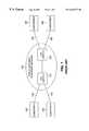
- FIG. 2Ais a block diagram illustrating the interconnection of CLEC equipment in the vicinity of the LEC switch of FIG. 1 by means of an unbundling demarcation device (UDD) according to the present invention
- FIG. 2Bis a block diagram illustrating the interconnection of CLEC equipment in the vicinity of the subscriber site of FIG. 1 by means of an unbundling demarcation device (UDD) according to the present invention.
- UDDunbundling demarcation device
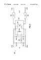
- FIG. 3is a schematic diagram illustrating one embodiment of the unbundling demarcation device (UDD) of FIGS. 2 A and 2 B.
- UDDunbundling demarcation device
- FIG. 1is a block diagram illustrating the conventional Public Switched Telephone Network (PSTN) 100 .
- PSTNPublic Switched Telephone Network
- the Public Switched Telephone Network (PSTN) 100interconnects a plurality of subscribers 130 , 140 , 150 , 160 by means of a plurality of telephone switches 110 , 120 , such as the 5ESS® switch, manufactured by Lucent Technologies Inc. of Murray Hill, N.J., operated by one or more local exchange carriers (LECs).
- Each subscriber 130 , 140 , 150 , 160is connected to the corresponding LEC switch, such as switches 110 , 120 , by means of a subscriber loop 135 , 145 , 155 , 165 , such as a twisted pair.
- a twisted pairconsists of a ring line and a tip line, in a known manner.
- a subscribersuch as subscriber 160
- the corresponding LEC 120must unbundle the subscriber loop 165 to permit CLEC access.
- CLEClocal exchange carrier
- the LEC 120utilizes an unbundling demarcation device (UDD) 220 , discussed further below in conjunction with FIGS. 2A, 2 B and 3 , to disconnect the LEC's equipment 120 from the subscriber 160 and to permit a CLEC 210 (FIGS. 2A and 2B) to provide local service to a subscriber 160 .
- the CLEC equipment 210may be connected to the subscriber 160 by means of a CLEC twisted pair 230 and the unbundling demarcation device (UDD) 220 .
- the unbundling demarcation device (UDD) 220 and related CLEC equipment 210may be positioned in the vicinity of the LEC switch 120 , as shown in FIG. 2A, or positioned in the vicinity of the subscriber 160 , as shown in FIG. 2 B.
- the unbundling demarcation device (UDD)is embodied as an electromechanical or electro-optical coupling device, such as a sensitive relay, a latching relay or a switching mechanism, that transparently connects the LEC equipment 120 to the CLEC equipment 210 when an appropriate control signal is applied to the subscriber loop 165 by the LEC switch 120 .
- the control signalmay be an electrical or optical signal, including a DC voltage, for example, the 48 volts present in the well known Plain Old Telephone Service (POTS) system or a Private Branch Exchange (PBX) system, or a trigger signal, for example, in a network that does not exhibit a battery feed, such as an Integrated Services Digital Network (ISDN).
- An optical control signalmay be generated, for example, by an infrared light emitting diode (IR LED).
- IR LEDinfrared light emitting diode
- the unbundling demarcation device (UDD) 220In the event the LEC removes the voltage from the subscriber loop 165 , or when a deactivating control signal is applied, the unbundling demarcation device (UDD) 220 will open circuit or decouple, and prevent the LEC from accessing the subscriber equipment and allow the CLEC to access the subscriber 160 . In order to prevent “ring trip,” where an insufficient amount of current on the twisted pair 165 causes the line to be answered (or to appear busy) when not wanted, or transmission impairment problems, such as low volume or poor signal strength, the current drawn by the unbundling demarcation device (UDD) 220 when in the activated state should be limited. According to one feature of the invention, the operation of the unbundling demarcation device (UDD) 220 is independent of the condition of the CLEC loop 230 or subscriber equipment 160 .
- the unbundling demarcation device (UDD) 220operates as a maintenance termination unit (MTU) and can be utilized to determine whether there is a fault, such as a short or open sufficient to cause transmission problems, in the subscriber loop 165 up to and beyond the unbundling demarcation device (UDD) 220 .
- a maintenance termination unit (MTU)is a well known fault sectionalization device used by the LEC on a subscriber loop to determine the location of a fault at a point on the subscriber loop 165 relative to the location of the respective maintenance termination unit (MTU).
- the unbundling demarcation device (UDD) 220disconnects the subscriber 160 and CLEC equipment 210 , and the LEC 120 can evaluate the subscriber loop 165 all the way to the unbundling demarcation device (UDD) 220 .
- the LEC 120can evaluate the CLEC loop 230 and customer equipment 160 for faults as well.
- the unbundling demarcation device (UDD) 220is preferably an electrically passive device.
- the unbundling demarcation device (UDD) 220is effectively transparent to the subscriber loop 165 when deactivated, unlike conventional MTUs whose presence in the subscriber loop 165 is not at all transparent.
- the preferred embodiment of the unbundling demarcation device (UDD) 220is shown in FIG. 3 .
- the ring line 310 a and tip line 320 a of the twisted pair provided by the LECwill be connected to the ring line 310 b and tip line 320 b of the twisted pair provided by the CLEC, if an appropriate voltage or trigger signal is applied by the LEC across the lines 310 a , 320 a .
- the appropriate voltagemay be 48 volts ( ⁇ 6V).
- the unbundling demarcation device (UDD) 220includes a sensitive 48 Volt relay 350 with contacts 354 , 356 that close when an appropriate amount of dc current (on the order of 200 ⁇ A) flows from the LEC, for example, from a battery or other power source.
- the unbundling demarcation device (UDD) 220may be embodied as a latching relay.
- the ISDN networkis a global telecommunication service that uses digital transmission and switching teclmology to support voice and digital data communication.
- the DC resistance of the relay pick-up coil 352is preferably approximately 100 Kohms through a polarity bridge 332 , 334 , 336 , 338 .
- the polarity bridge 332 , 334 , 336 , 338allows operation in either polarity, thereby permitting operation of the unbundling demarcation device (UDD) 220 , for example, if the wires 310 a , 320 a are cut and repaired with an opposite polarity.
- the unbundling demarcation device (UDD) 220may alternatively be embodied as a latching relay.
- a latching relayis activated and deactivated by voltage signals of opposite polarities or other appropriate activation and deactivation control signals.
- the polarity bridgeshould be removed from the unbundling demarcation device (UDD) 220 .
- UDDunbundling demarcation device
- a current limiting resistor 340provides an appropriate impedance to prevent the current drawn by the relay pick-up coil 352 from creating a “ring trip” condition, in a known manner.
- the unbundling demarcation device (UDD) 220preferably includes a ring line feed resistor 362 and a tip line feed resistor 364 , each on the order of 20 ohms, to allow the unbundling demarcation device (UDD) 220 to operate even if the CLEC loop or subscriber equipment is shorted or grounded.
- the ring line feed resistor 362 and tip line feed resistor 364also reduce the fault current to prevent lightning and other electrical surges from damaging the unbundling demarcation device (UDD) 220 , as well as the CLEC loop and subscriber equipment.
Landscapes
- Engineering & Computer Science (AREA)
- Signal Processing (AREA)
- Monitoring And Testing Of Exchanges (AREA)
Abstract
Description
Claims (26)
Priority Applications (1)
| Application Number | Priority Date | Filing Date | Title |
|---|---|---|---|
| US08/980,237US6282277B1 (en) | 1997-11-28 | 1997-11-28 | Unbundling device and method for connecting a competing local exchange carrier (CLEC) to the subscriber loop of a local exchange carrier (LEC) |
Applications Claiming Priority (1)
| Application Number | Priority Date | Filing Date | Title |
|---|---|---|---|
| US08/980,237US6282277B1 (en) | 1997-11-28 | 1997-11-28 | Unbundling device and method for connecting a competing local exchange carrier (CLEC) to the subscriber loop of a local exchange carrier (LEC) |
Publications (1)
| Publication Number | Publication Date |
|---|---|
| US6282277B1true US6282277B1 (en) | 2001-08-28 |
Family
ID=25527425
Family Applications (1)
| Application Number | Title | Priority Date | Filing Date |
|---|---|---|---|
| US08/980,237Expired - Fee RelatedUS6282277B1 (en) | 1997-11-28 | 1997-11-28 | Unbundling device and method for connecting a competing local exchange carrier (CLEC) to the subscriber loop of a local exchange carrier (LEC) |
Country Status (1)
| Country | Link |
|---|---|
| US (1) | US6282277B1 (en) |
Cited By (14)
| Publication number | Priority date | Publication date | Assignee | Title |
|---|---|---|---|---|
| US20030027521A1 (en)* | 2001-08-01 | 2003-02-06 | Adrian Yip | Method for seamless port capability for an alternative service provider |
| US6744871B2 (en)* | 2000-05-12 | 2004-06-01 | Alcatel | Method for routing service calls in a telecommunication network, as well as a telecommunication network, switching center and program module therefor |
| US20050117732A1 (en)* | 2002-01-25 | 2005-06-02 | Claude Arpin | Automatic telephone line switch |
| US20050254431A1 (en)* | 2004-05-13 | 2005-11-17 | Sills Daniel J | Method and system for surveilling a telecommunications network link |
| US20070036172A1 (en)* | 2005-07-18 | 2007-02-15 | Tingting Lu | Methods, systems, and computer program products for provisioning a digital subscriber line in which an incumbent local exchange carrier activates a line number port on behalf of a competitive local exchange carrier |
| US7397791B2 (en) | 2000-04-18 | 2008-07-08 | Serconet, Ltd. | Telephone communication system over a single telephone line |
| US20080219282A1 (en)* | 2007-03-09 | 2008-09-11 | Adc Gmbh | Customer termination point in the subscriber premises of a telecommunication and/or data link and method for changing providers |
| US7436842B2 (en) | 2001-10-11 | 2008-10-14 | Serconet Ltd. | Outlet with analog signal adapter, a method for use thereof and a network using said outlet |
| US7522714B2 (en) | 2000-03-20 | 2009-04-21 | Serconet Ltd. | Telephone outlet for implementing a local area network over telephone lines and a local area network using such outlets |
| US7542554B2 (en) | 2001-07-05 | 2009-06-02 | Serconet, Ltd | Telephone outlet with packet telephony adapter, and a network using same |
| US7656904B2 (en) | 2003-03-13 | 2010-02-02 | Mosaid Technologies Incorporated | Telephone system having multiple distinct sources and accessories therefor |
| US7873058B2 (en) | 2004-11-08 | 2011-01-18 | Mosaid Technologies Incorporated | Outlet with analog signal adapter, a method for use thereof and a network using said outlet |
| US8325636B2 (en) | 1998-07-28 | 2012-12-04 | Mosaid Technologies Incorporated | Local area network of serial intelligent cells |
| US10986164B2 (en) | 2004-01-13 | 2021-04-20 | May Patents Ltd. | Information device |
Citations (13)
| Publication number | Priority date | Publication date | Assignee | Title |
|---|---|---|---|---|
| US3803360A (en)* | 1972-06-02 | 1974-04-09 | Gte Automatic Electric Lab Inc | Switching apparatus for connecting a data terminal to a plurality of communications networks |
| US4197427A (en)* | 1977-11-11 | 1980-04-08 | Lynch Communication Systems, Inc. | Dual-processor line concentrator switching system |
| US4887295A (en)* | 1986-07-14 | 1989-12-12 | Siliconix Limited | Telephone instrument |
| US5287344A (en)* | 1991-06-05 | 1994-02-15 | At&T Bell Laboratories | Transferring lines in a digital loop carrier transmission system |
| US5341415A (en)* | 1992-09-22 | 1994-08-23 | Paul Baran | Method and apparatus for sharing of common in-house wiring to permit multiple telephone carriers to serve the same customer |
| US5408525A (en)* | 1994-05-24 | 1995-04-18 | General Instrument Corporation Of Delaware | Diverter interface between two telecommunication lines and a station set |
| US5563938A (en)* | 1995-04-07 | 1996-10-08 | Teltone Corporation | Subscriber telephone diverter switch |
| US5673255A (en)* | 1995-12-28 | 1997-09-30 | Lucent Technologies Inc. | Apparatus for providing service to telephone subscribers connected to a remote terminal from multiple telephone service providers |
| US5715305A (en)* | 1995-09-21 | 1998-02-03 | At&T Corp. | Apparatus for and method of providing consumers with local access carrier |
| US5784449A (en)* | 1995-12-05 | 1998-07-21 | Lucent Technologies Inc. | Telecommunications network for serving users from two switches |
| US5903639A (en)* | 1996-11-21 | 1999-05-11 | Bellatlantic Services, Inc. | Custom routing for multiple carrier interconnection |
| US6072793A (en)* | 1997-06-12 | 2000-06-06 | Lucent Technologies Inc. | Electronically controlled main distributing frame |
| US6160880A (en)* | 1998-04-02 | 2000-12-12 | Bell Atlantic Network Services, Inc. | Local number portability service saver |
- 1997
- 1997-11-28USUS08/980,237patent/US6282277B1/ennot_activeExpired - Fee Related
Patent Citations (13)
| Publication number | Priority date | Publication date | Assignee | Title |
|---|---|---|---|---|
| US3803360A (en)* | 1972-06-02 | 1974-04-09 | Gte Automatic Electric Lab Inc | Switching apparatus for connecting a data terminal to a plurality of communications networks |
| US4197427A (en)* | 1977-11-11 | 1980-04-08 | Lynch Communication Systems, Inc. | Dual-processor line concentrator switching system |
| US4887295A (en)* | 1986-07-14 | 1989-12-12 | Siliconix Limited | Telephone instrument |
| US5287344A (en)* | 1991-06-05 | 1994-02-15 | At&T Bell Laboratories | Transferring lines in a digital loop carrier transmission system |
| US5341415A (en)* | 1992-09-22 | 1994-08-23 | Paul Baran | Method and apparatus for sharing of common in-house wiring to permit multiple telephone carriers to serve the same customer |
| US5408525A (en)* | 1994-05-24 | 1995-04-18 | General Instrument Corporation Of Delaware | Diverter interface between two telecommunication lines and a station set |
| US5563938A (en)* | 1995-04-07 | 1996-10-08 | Teltone Corporation | Subscriber telephone diverter switch |
| US5715305A (en)* | 1995-09-21 | 1998-02-03 | At&T Corp. | Apparatus for and method of providing consumers with local access carrier |
| US5784449A (en)* | 1995-12-05 | 1998-07-21 | Lucent Technologies Inc. | Telecommunications network for serving users from two switches |
| US5673255A (en)* | 1995-12-28 | 1997-09-30 | Lucent Technologies Inc. | Apparatus for providing service to telephone subscribers connected to a remote terminal from multiple telephone service providers |
| US5903639A (en)* | 1996-11-21 | 1999-05-11 | Bellatlantic Services, Inc. | Custom routing for multiple carrier interconnection |
| US6072793A (en)* | 1997-06-12 | 2000-06-06 | Lucent Technologies Inc. | Electronically controlled main distributing frame |
| US6160880A (en)* | 1998-04-02 | 2000-12-12 | Bell Atlantic Network Services, Inc. | Local number portability service saver |
Cited By (43)
| Publication number | Priority date | Publication date | Assignee | Title |
|---|---|---|---|---|
| US8325636B2 (en) | 1998-07-28 | 2012-12-04 | Mosaid Technologies Incorporated | Local area network of serial intelligent cells |
| US8908673B2 (en) | 1998-07-28 | 2014-12-09 | Conversant Intellectual Property Management Incorporated | Local area network of serial intelligent cells |
| US8885659B2 (en) | 1998-07-28 | 2014-11-11 | Conversant Intellectual Property Management Incorporated | Local area network of serial intelligent cells |
| US8885660B2 (en) | 1998-07-28 | 2014-11-11 | Conversant Intellectual Property Management Incorporated | Local area network of serial intelligent cells |
| US8867523B2 (en) | 1998-07-28 | 2014-10-21 | Conversant Intellectual Property Management Incorporated | Local area network of serial intelligent cells |
| US7715534B2 (en) | 2000-03-20 | 2010-05-11 | Mosaid Technologies Incorporated | Telephone outlet for implementing a local area network over telephone lines and a local area network using such outlets |
| US7522714B2 (en) | 2000-03-20 | 2009-04-21 | Serconet Ltd. | Telephone outlet for implementing a local area network over telephone lines and a local area network using such outlets |
| US8855277B2 (en) | 2000-03-20 | 2014-10-07 | Conversant Intellectual Property Managment Incorporated | Telephone outlet for implementing a local area network over telephone lines and a local area network using such outlets |
| US8363797B2 (en) | 2000-03-20 | 2013-01-29 | Mosaid Technologies Incorporated | Telephone outlet for implementing a local area network over telephone lines and a local area network using such outlets |
| US8559422B2 (en) | 2000-04-18 | 2013-10-15 | Mosaid Technologies Incorporated | Telephone communication system over a single telephone line |
| US7466722B2 (en) | 2000-04-18 | 2008-12-16 | Serconet Ltd | Telephone communication system over a single telephone line |
| US7397791B2 (en) | 2000-04-18 | 2008-07-08 | Serconet, Ltd. | Telephone communication system over a single telephone line |
| US8223800B2 (en) | 2000-04-18 | 2012-07-17 | Mosaid Technologies Incorporated | Telephone communication system over a single telephone line |
| US6744871B2 (en)* | 2000-05-12 | 2004-06-01 | Alcatel | Method for routing service calls in a telecommunication network, as well as a telecommunication network, switching center and program module therefor |
| US7769030B2 (en) | 2001-07-05 | 2010-08-03 | Mosaid Technologies Incorporated | Telephone outlet with packet telephony adapter, and a network using same |
| US8761186B2 (en) | 2001-07-05 | 2014-06-24 | Conversant Intellectual Property Management Incorporated | Telephone outlet with packet telephony adapter, and a network using same |
| US7542554B2 (en) | 2001-07-05 | 2009-06-02 | Serconet, Ltd | Telephone outlet with packet telephony adapter, and a network using same |
| US8472593B2 (en) | 2001-07-05 | 2013-06-25 | Mosaid Technologies Incorporated | Telephone outlet with packet telephony adaptor, and a network using same |
| US7680255B2 (en) | 2001-07-05 | 2010-03-16 | Mosaid Technologies Incorporated | Telephone outlet with packet telephony adaptor, and a network using same |
| WO2003013115A3 (en)* | 2001-08-01 | 2003-05-30 | At & T Wireless Services Inc | A method for seamless port capability for an alternative service provider |
| US6898413B2 (en)* | 2001-08-01 | 2005-05-24 | Clearwire Corporation | Method for seamless port capability for an alternative service provider |
| US20030027521A1 (en)* | 2001-08-01 | 2003-02-06 | Adrian Yip | Method for seamless port capability for an alternative service provider |
| US7889720B2 (en) | 2001-10-11 | 2011-02-15 | Mosaid Technologies Incorporated | Outlet with analog signal adapter, a method for use thereof and a network using said outlet |
| US7453895B2 (en) | 2001-10-11 | 2008-11-18 | Serconet Ltd | Outlet with analog signal adapter, a method for use thereof and a network using said outlet |
| US7860084B2 (en) | 2001-10-11 | 2010-12-28 | Mosaid Technologies Incorporated | Outlet with analog signal adapter, a method for use thereof and a network using said outlet |
| US7436842B2 (en) | 2001-10-11 | 2008-10-14 | Serconet Ltd. | Outlet with analog signal adapter, a method for use thereof and a network using said outlet |
| US7953071B2 (en) | 2001-10-11 | 2011-05-31 | Mosaid Technologies Incorporated | Outlet with analog signal adapter, a method for use thereof and a network using said outlet |
| US7315615B2 (en)* | 2002-01-25 | 2008-01-01 | Sittelle Technologies, Inc. | Automatic telephone line switch |
| US20050117732A1 (en)* | 2002-01-25 | 2005-06-02 | Claude Arpin | Automatic telephone line switch |
| US7656904B2 (en) | 2003-03-13 | 2010-02-02 | Mosaid Technologies Incorporated | Telephone system having multiple distinct sources and accessories therefor |
| US7738453B2 (en) | 2003-03-13 | 2010-06-15 | Mosaid Technologies Incorporated | Telephone system having multiple sources and accessories therefor |
| US8238328B2 (en) | 2003-03-13 | 2012-08-07 | Mosaid Technologies Incorporated | Telephone system having multiple distinct sources and accessories therefor |
| US7746905B2 (en) | 2003-03-13 | 2010-06-29 | Mosaid Technologies Incorporated | Private telephone network connected to more than one public network |
| US10986164B2 (en) | 2004-01-13 | 2021-04-20 | May Patents Ltd. | Information device |
| US11095708B2 (en) | 2004-01-13 | 2021-08-17 | May Patents Ltd. | Information device |
| US10986165B2 (en) | 2004-01-13 | 2021-04-20 | May Patents Ltd. | Information device |
| US20050254431A1 (en)* | 2004-05-13 | 2005-11-17 | Sills Daniel J | Method and system for surveilling a telecommunications network link |
| US7486623B2 (en)* | 2004-05-13 | 2009-02-03 | General Instrument Corporation | Method and system for surveilling a telecommunications network link |
| US7873058B2 (en) | 2004-11-08 | 2011-01-18 | Mosaid Technologies Incorporated | Outlet with analog signal adapter, a method for use thereof and a network using said outlet |
| US20070036172A1 (en)* | 2005-07-18 | 2007-02-15 | Tingting Lu | Methods, systems, and computer program products for provisioning a digital subscriber line in which an incumbent local exchange carrier activates a line number port on behalf of a competitive local exchange carrier |
| DE102007011683A1 (en)* | 2007-03-09 | 2008-09-11 | Adc Gmbh | Termination point line in the subscriber area of a telecommunication and / or data connection and method for provider change |
| US20080219282A1 (en)* | 2007-03-09 | 2008-09-11 | Adc Gmbh | Customer termination point in the subscriber premises of a telecommunication and/or data link and method for changing providers |
| DE102007011683B4 (en)* | 2007-03-09 | 2009-06-10 | Adc Gmbh | Termination point line in the subscriber area of a telecommunication and / or data connection and method for provider change |
Similar Documents
| Publication | Publication Date | Title |
|---|---|---|
| US6282277B1 (en) | Unbundling device and method for connecting a competing local exchange carrier (CLEC) to the subscriber loop of a local exchange carrier (LEC) | |
| US7961864B2 (en) | Local number portability cross connect method | |
| CA1217286A (en) | Maintenance termination unit | |
| US6453016B1 (en) | Method and apparatus for detecting and locating a fault in a telecommunications environment | |
| US4998240A (en) | Method of and system for remote testing of integrated services digital networks | |
| US5636202A (en) | Test system for detecting ISDN NT1-U interfaces | |
| US8208385B1 (en) | Method and apparatus for testing communications between a network edge device and a customer premises device | |
| US6741675B2 (en) | Method and apparatus for generating an audible tone in DSL environment | |
| US6757382B1 (en) | Quasi ground fault interruption signal-based activation of emergency pots by-pass paths for line-powered digital subscriber loop | |
| AU645658B2 (en) | Submarine telecommunications systems | |
| CN1200217A (en) | A telecommunications switch | |
| US5115462A (en) | Remotely controlled apparatus for conditioning telephone line exclusive of metallic DC bypass pair | |
| US6362630B1 (en) | Electronic test tag for wireline continuity verification | |
| NZ286257A (en) | Telephone line lightning protection in maintenance termination unit | |
| US5719917A (en) | Circuit for activating back-up lines | |
| US5524043A (en) | Remotely connectable maintenance termination unit | |
| US6292540B1 (en) | Battery injection and loop supervision for DSL environment | |
| US7203306B2 (en) | Apparatus and method for providing switching at a telephone cross-connect | |
| US7349526B2 (en) | Methods for testing cable pairs in a telecommunications network | |
| US2810016A (en) | Key telephone set holding circuit | |
| US5612995A (en) | Method for activating a lamp on analog customer premises equipment by a digital signal | |
| CN1150743C (en) | Subscriber connection circuits for analog subscriber lines connected to digital time-division multiplexing telephone exchanges | |
| US4252997A (en) | Circuit for interfacing non-dial telephone and automatic switch equipment | |
| US4633040A (en) | Personal branch exchange system | |
| US5828728A (en) | Telecommunications network |
Legal Events
| Date | Code | Title | Description |
|---|---|---|---|
| AS | Assignment | Owner name:LUCENT TECHNOLOGIES INC., NEW JERSEY Free format text:ASSIGNMENT OF ASSIGNORS INTEREST;ASSIGNOR:DEBALKO, GEORGE ANDREW;REEL/FRAME:008845/0600 Effective date:19971126 | |
| AS | Assignment | Owner name:AVAYA TECHNOLOGY CORP., NEW JERSEY Free format text:ASSIGNMENT OF ASSIGNORS INTEREST;ASSIGNOR:LUCENT TECHNOLOGIES INC.;REEL/FRAME:011872/0118 Effective date:20000929 | |
| AS | Assignment | Owner name:BANK OF NEW YORK, THE, NEW YORK Free format text:SECURITY AGREEMENT;ASSIGNOR:AVAYA TECHNOLOGY CORP.;REEL/FRAME:012775/0144 Effective date:20020405 | |
| FPAY | Fee payment | Year of fee payment:4 | |
| AS | Assignment | Owner name:AVAYA TECHNOLOGY CORPORATION, NEW JERSEY Free format text:RELEASE BY SECURED PARTY;ASSIGNOR:THE BANK OF NEW YORK;REEL/FRAME:019881/0532 Effective date:20040101 | |
| AS | Assignment | Owner name:COMMSCOPE SOLUTIONS PROPERTIES, LLC, NEVADA Free format text:ASSIGNMENT OF ASSIGNORS INTEREST;ASSIGNOR:AVAYA TECHNOLOGY CORPORATION;REEL/FRAME:019984/0028 Effective date:20040129 | |
| AS | Assignment | Owner name:COMMSCOPE, INC. OF NORTH CAROLINA, NORTH CAROLINA Free format text:MERGER;ASSIGNOR:COMMSCOPE SOLUTIONS PROPERTIES, LLC;REEL/FRAME:019991/0643 Effective date:20061220 Owner name:COMMSCOPE, INC. OF NORTH CAROLINA,NORTH CAROLINA Free format text:MERGER;ASSIGNOR:COMMSCOPE SOLUTIONS PROPERTIES, LLC;REEL/FRAME:019991/0643 Effective date:20061220 | |
| AS | Assignment | Owner name:BANK OF AMERICA, N.A., AS ADMINISTRATIVE AGENT, CA Free format text:SECURITY AGREEMENT;ASSIGNORS:COMMSCOPE, INC. OF NORTH CAROLINA;ALLEN TELECOM, LLC;ANDREW CORPORATION;REEL/FRAME:020362/0241 Effective date:20071227 Owner name:BANK OF AMERICA, N.A., AS ADMINISTRATIVE AGENT,CAL Free format text:SECURITY AGREEMENT;ASSIGNORS:COMMSCOPE, INC. OF NORTH CAROLINA;ALLEN TELECOM, LLC;ANDREW CORPORATION;REEL/FRAME:020362/0241 Effective date:20071227 | |
| FPAY | Fee payment | Year of fee payment:8 | |
| AS | Assignment | Owner name:COMMSCOPE, INC. OF NORTH CAROLINA, NORTH CAROLINA Free format text:PATENT RELEASE;ASSIGNOR:BANK OF AMERICA, N.A., AS ADMINISTRATIVE AGENT;REEL/FRAME:026039/0005 Effective date:20110114 Owner name:ANDREW LLC (F/K/A ANDREW CORPORATION), NORTH CAROL Free format text:PATENT RELEASE;ASSIGNOR:BANK OF AMERICA, N.A., AS ADMINISTRATIVE AGENT;REEL/FRAME:026039/0005 Effective date:20110114 Owner name:ALLEN TELECOM LLC, NORTH CAROLINA Free format text:PATENT RELEASE;ASSIGNOR:BANK OF AMERICA, N.A., AS ADMINISTRATIVE AGENT;REEL/FRAME:026039/0005 Effective date:20110114 | |
| AS | Assignment | Owner name:JPMORGAN CHASE BANK, N.A., AS COLLATERAL AGENT, NE Free format text:SECURITY AGREEMENT;ASSIGNORS:ALLEN TELECOM LLC, A DELAWARE LLC;ANDREW LLC, A DELAWARE LLC;COMMSCOPE, INC. OF NORTH CAROLINA, A NORTH CAROLINA CORPORATION;REEL/FRAME:026276/0363 Effective date:20110114 | |
| AS | Assignment | Owner name:JPMORGAN CHASE BANK, N.A., AS COLLATERAL AGENT, NE Free format text:SECURITY AGREEMENT;ASSIGNORS:ALLEN TELECOM LLC, A DELAWARE LLC;ANDREW LLC, A DELAWARE LLC;COMMSCOPE, INC OF NORTH CAROLINA, A NORTH CAROLINA CORPORATION;REEL/FRAME:026272/0543 Effective date:20110114 | |
| REMI | Maintenance fee reminder mailed | ||
| LAPS | Lapse for failure to pay maintenance fees | ||
| STCH | Information on status: patent discontinuation | Free format text:PATENT EXPIRED DUE TO NONPAYMENT OF MAINTENANCE FEES UNDER 37 CFR 1.362 | |
| FP | Lapsed due to failure to pay maintenance fee | Effective date:20130828 | |
| AS | Assignment | Owner name:AVAYA INC. (FORMERLY KNOWN AS AVAYA TECHNOLOGY COR Free format text:BANKRUPTCY COURT ORDER RELEASING ALL LIENS INCLUDING THE SECURITY INTEREST RECORDED AT REEL/FRAME 012775/0144;ASSIGNOR:THE BANK OF NEW YORK;REEL/FRAME:044893/0179 Effective date:20171128 | |
| AS | Assignment | Owner name:COMMSCOPE TECHNOLOGIES LLC, NORTH CAROLINA Free format text:RELEASE BY SECURED PARTY;ASSIGNOR:JPMORGAN CHASE BANK, N.A.;REEL/FRAME:048840/0001 Effective date:20190404 Owner name:ALLEN TELECOM LLC, ILLINOIS Free format text:RELEASE BY SECURED PARTY;ASSIGNOR:JPMORGAN CHASE BANK, N.A.;REEL/FRAME:048840/0001 Effective date:20190404 Owner name:COMMSCOPE, INC. OF NORTH CAROLINA, NORTH CAROLINA Free format text:RELEASE BY SECURED PARTY;ASSIGNOR:JPMORGAN CHASE BANK, N.A.;REEL/FRAME:048840/0001 Effective date:20190404 Owner name:REDWOOD SYSTEMS, INC., NORTH CAROLINA Free format text:RELEASE BY SECURED PARTY;ASSIGNOR:JPMORGAN CHASE BANK, N.A.;REEL/FRAME:048840/0001 Effective date:20190404 Owner name:ANDREW LLC, NORTH CAROLINA Free format text:RELEASE BY SECURED PARTY;ASSIGNOR:JPMORGAN CHASE BANK, N.A.;REEL/FRAME:048840/0001 Effective date:20190404 Owner name:REDWOOD SYSTEMS, INC., NORTH CAROLINA Free format text:RELEASE BY SECURED PARTY;ASSIGNOR:JPMORGAN CHASE BANK, N.A.;REEL/FRAME:049260/0001 Effective date:20190404 Owner name:COMMSCOPE, INC. OF NORTH CAROLINA, NORTH CAROLINA Free format text:RELEASE BY SECURED PARTY;ASSIGNOR:JPMORGAN CHASE BANK, N.A.;REEL/FRAME:049260/0001 Effective date:20190404 Owner name:ANDREW LLC, NORTH CAROLINA Free format text:RELEASE BY SECURED PARTY;ASSIGNOR:JPMORGAN CHASE BANK, N.A.;REEL/FRAME:049260/0001 Effective date:20190404 Owner name:ALLEN TELECOM LLC, ILLINOIS Free format text:RELEASE BY SECURED PARTY;ASSIGNOR:JPMORGAN CHASE BANK, N.A.;REEL/FRAME:049260/0001 Effective date:20190404 Owner name:COMMSCOPE TECHNOLOGIES LLC, NORTH CAROLINA Free format text:RELEASE BY SECURED PARTY;ASSIGNOR:JPMORGAN CHASE BANK, N.A.;REEL/FRAME:049260/0001 Effective date:20190404 |