US6282189B1 - Unified access platform for simultaneously delivering voice and cell-based services - Google Patents
Unified access platform for simultaneously delivering voice and cell-based servicesDownload PDFInfo
- Publication number
- US6282189B1 US6282189B1US08/905,775US90577597AUS6282189B1US 6282189 B1US6282189 B1US 6282189B1US 90577597 AUS90577597 AUS 90577597AUS 6282189 B1US6282189 B1US 6282189B1
- Authority
- US
- United States
- Prior art keywords
- cell
- signal
- signals
- telephony
- combined
- Prior art date
- Legal status (The legal status is an assumption and is not a legal conclusion. Google has not performed a legal analysis and makes no representation as to the accuracy of the status listed.)
- Expired - Lifetime
Links
- 238000000034methodMethods0.000claimsdescription52
- 239000000835fiberSubstances0.000claimsdescription12
- 238000013507mappingMethods0.000claimsdescription10
- 238000012546transferMethods0.000claimsdescription3
- 101150012579ADSL geneProteins0.000claims6
- 102100020775Adenylosuccinate lyaseHuman genes0.000claims6
- 108700040193Adenylosuccinate lyasesProteins0.000claims6
- 230000005540biological transmissionEffects0.000description39
- 239000013307optical fiberSubstances0.000description21
- LSWOCDLIYSKTRX-UHFFFAOYSA-N1-butyl-1-nitrosoureaChemical compoundCCCCN(N=O)C(N)=OLSWOCDLIYSKTRX-UHFFFAOYSA-N0.000description15
- 230000003287optical effectEffects0.000description12
- 238000005516engineering processMethods0.000description7
- 230000011664signalingEffects0.000description7
- 238000011144upstream manufacturingMethods0.000description6
- 239000008186active pharmaceutical agentSubstances0.000description3
- 238000013459approachMethods0.000description3
- 239000000284extractSubstances0.000description3
- 238000001228spectrumMethods0.000description3
- 230000008901benefitEffects0.000description2
- 239000004020conductorSubstances0.000description2
- 230000003370grooming effectEffects0.000description2
- 238000009434installationMethods0.000description2
- 238000007726management methodMethods0.000description2
- 239000000203mixtureSubstances0.000description2
- 230000001360synchronised effectEffects0.000description2
- 238000012360testing methodMethods0.000description2
- RYGMFSIKBFXOCR-UHFFFAOYSA-NCopperChemical compound[Cu]RYGMFSIKBFXOCR-UHFFFAOYSA-N0.000description1
- 230000003044adaptive effectEffects0.000description1
- 230000015572biosynthetic processEffects0.000description1
- 238000006243chemical reactionMethods0.000description1
- 238000001816coolingMethods0.000description1
- 238000012937correctionMethods0.000description1
- 230000001627detrimental effectEffects0.000description1
- 238000011161developmentMethods0.000description1
- 230000018109developmental processEffects0.000description1
- 230000009977dual effectEffects0.000description1
- 238000003780insertionMethods0.000description1
- 230000037431insertionEffects0.000description1
- 230000002452interceptive effectEffects0.000description1
- 230000007774longtermEffects0.000description1
- 238000012986modificationMethods0.000description1
- 230000004048modificationEffects0.000description1
- 230000035515penetrationEffects0.000description1
- 230000010363phase shiftEffects0.000description1
- 230000000135prohibitive effectEffects0.000description1
- 238000002310reflectometryMethods0.000description1
- 230000000007visual effectEffects0.000description1
Images


Classifications
- H—ELECTRICITY
- H04—ELECTRIC COMMUNICATION TECHNIQUE
- H04L—TRANSMISSION OF DIGITAL INFORMATION, e.g. TELEGRAPHIC COMMUNICATION
- H04L12/00—Data switching networks
- H04L12/54—Store-and-forward switching systems
- H04L12/56—Packet switching systems
- H04L12/5601—Transfer mode dependent, e.g. ATM
- H—ELECTRICITY
- H04—ELECTRIC COMMUNICATION TECHNIQUE
- H04L—TRANSMISSION OF DIGITAL INFORMATION, e.g. TELEGRAPHIC COMMUNICATION
- H04L12/00—Data switching networks
- H04L12/28—Data switching networks characterised by path configuration, e.g. LAN [Local Area Networks] or WAN [Wide Area Networks]
- H04L12/2801—Broadband local area networks
- H—ELECTRICITY
- H04—ELECTRIC COMMUNICATION TECHNIQUE
- H04L—TRANSMISSION OF DIGITAL INFORMATION, e.g. TELEGRAPHIC COMMUNICATION
- H04L12/00—Data switching networks
- H04L12/28—Data switching networks characterised by path configuration, e.g. LAN [Local Area Networks] or WAN [Wide Area Networks]
- H04L12/2854—Wide area networks, e.g. public data networks
- H04L12/2856—Access arrangements, e.g. Internet access
- H04L12/2869—Operational details of access network equipments
- H04L12/2878—Access multiplexer, e.g. DSLAM
- H04L12/2879—Access multiplexer, e.g. DSLAM characterised by the network type on the uplink side, i.e. towards the service provider network
- H04L12/2881—IP/Ethernet DSLAM
- H—ELECTRICITY
- H04—ELECTRIC COMMUNICATION TECHNIQUE
- H04L—TRANSMISSION OF DIGITAL INFORMATION, e.g. TELEGRAPHIC COMMUNICATION
- H04L12/00—Data switching networks
- H04L12/28—Data switching networks characterised by path configuration, e.g. LAN [Local Area Networks] or WAN [Wide Area Networks]
- H04L12/2854—Wide area networks, e.g. public data networks
- H04L12/2856—Access arrangements, e.g. Internet access
- H04L12/2869—Operational details of access network equipments
- H04L12/2898—Subscriber equipments
- H—ELECTRICITY
- H04—ELECTRIC COMMUNICATION TECHNIQUE
- H04L—TRANSMISSION OF DIGITAL INFORMATION, e.g. TELEGRAPHIC COMMUNICATION
- H04L5/00—Arrangements affording multiple use of the transmission path
- H04L5/20—Arrangements affording multiple use of the transmission path using different combinations of lines, e.g. phantom working
- H—ELECTRICITY
- H04—ELECTRIC COMMUNICATION TECHNIQUE
- H04M—TELEPHONIC COMMUNICATION
- H04M7/00—Arrangements for interconnection between switching centres
- H04M7/0003—Interconnection between telephone networks and data networks
- H—ELECTRICITY
- H04—ELECTRIC COMMUNICATION TECHNIQUE
- H04Q—SELECTING
- H04Q11/00—Selecting arrangements for multiplex systems
- H04Q11/04—Selecting arrangements for multiplex systems for time-division multiplexing
- H04Q11/0428—Integrated services digital network, i.e. systems for transmission of different types of digitised signals, e.g. speech, data, telecentral, television signals
- H04Q11/0478—Provisions for broadband connections
- H—ELECTRICITY
- H04—ELECTRIC COMMUNICATION TECHNIQUE
- H04L—TRANSMISSION OF DIGITAL INFORMATION, e.g. TELEGRAPHIC COMMUNICATION
- H04L12/00—Data switching networks
- H04L12/54—Store-and-forward switching systems
- H04L12/56—Packet switching systems
- H04L12/5601—Transfer mode dependent, e.g. ATM
- H04L2012/5603—Access techniques
- H04L2012/5609—Topology
- H04L2012/561—Star, e.g. cross-connect, concentrator, subscriber group equipment, remote electronics
- H—ELECTRICITY
- H04—ELECTRIC COMMUNICATION TECHNIQUE
- H04L—TRANSMISSION OF DIGITAL INFORMATION, e.g. TELEGRAPHIC COMMUNICATION
- H04L12/00—Data switching networks
- H04L12/54—Store-and-forward switching systems
- H04L12/56—Packet switching systems
- H04L12/5601—Transfer mode dependent, e.g. ATM
- H04L2012/5614—User Network Interface
- H04L2012/5615—Network termination, e.g. NT1, NT2, PBX
- H—ELECTRICITY
- H04—ELECTRIC COMMUNICATION TECHNIQUE
- H04L—TRANSMISSION OF DIGITAL INFORMATION, e.g. TELEGRAPHIC COMMUNICATION
- H04L12/00—Data switching networks
- H04L12/54—Store-and-forward switching systems
- H04L12/56—Packet switching systems
- H04L12/5601—Transfer mode dependent, e.g. ATM
- H04L2012/5638—Services, e.g. multimedia, GOS, QOS
- H04L2012/5663—Support of N-ISDN
Definitions
- the present inventionrelates to a Unified Access Platform (UAP) which is capable of providing telephone and high speed data services in a number of different local loop configurations.
- UAPUnified Access Platform
- New telecommunications servicessuch as Internet access are being offered by phone companies.
- Internet accessin addition to other new services such as digital television, which require special high speed connections from networks to residences.
- basic telecommunications servicessuch as Plain Old Telephony service (POTs) are at present the main source of revenue for telephone companies.
- POTsPlain Old Telephony service
- These servicesare typically provided from a telephone central office to the residences over twisted copper wire pairs which in some cases have been in place for many years, and in some cases have been recently upgraded.
- the part of the telecommunications network that connects a telephone central office to the subscriber residencesis known as the access network or the local loop.
- the local loop technologyis still based primarily on the use of twisted wire pairs, but some optical fiber has been used to reach terminals for telephone service. To date there has been little deployment of high speed digital data services.
- high speed data servicesrefers to any type of digital data service including Internet access and digital video.
- Access network equipment for telecommunications servicesmust be able to support POTs services as well as being able to support new digital services which will eventually have high penetration rates.
- HFCHybrid Fiber Coax
- FTTCFiber-to-the-Curb
- FTTHFiber-to-the-Home
- ADSLAsymmetrical Digital Subscriber Line
- VDSLVery high rate Digital Subscriber Line
- a central officemay be located in an area which has both urban and suburban characteristics (e.g. some old apartment buildings as well as new housing developments), so that a mixture of FTTC, ADSL, and VDSL technologies are required.
- PSTNPublic Switched Telecommunications Network
- the equipment for transmission and reception of high speed data signals over twisted wire pairmust be placed remote from the central office, and closer to the subscriber residence. This can be accomplished by putting a device called a channel bank near an existing Remote Terminal (RT) which provides analog telephone service.
- RTRemote Terminal
- the analog telephone signalFor transmission over the twisted wire pair, the analog telephone signal must be combined with the high speed data signal using a diplexor. At the residence, a diplexor is used to separate the signals again.
- high speed data and telephony signalsare received at a broadband digital terminal, and combined into a cell based signal which is transported to an access multiplexor.
- an analog phone signalis generated on a first linecard, and a high-speed data signal is generated on a second linecard.
- Analog telephone serviceis provided over a first twisted wire pair drop cable, while the high speed data service is provided over a second twisted wire pair drop cable.
- high speed data and telephony signalsare received at a broadband digital terminal, and combined into a cell based signal which is transported to two separate terminals.
- Analog telephone serviceis provided to a subscriber location over a twisted wire pair from the first terminal, while high speed data services are provided to a second subscriber location from the second terminal.
- Another feature of the present inventionis the ability to provide analog telephone and high speed data services from a single linecard located in an access multiplexor.
- the analog telephone and high speed data signalsare generated on the linecard and combined using a diplexor.
- a receiving diplexoris used to separate the analog telephone and high speed data signals.
- An alternate embodiment for simultaneous delivery of telephone service and high speed datais to generate a high speed data signal at an access multiplexor which contains a digital representation of the analog telephone signal.
- the high speed data signalis sent from the access multiplexor to the residence, where a receiving device generates an analog telephony signal and transmits the high speed data signal to the appropriate terminal equipment.
- ATMAsynchronous Transport Mode
- the access equipmentcan be configured such that analog telephone service can be provided to subscribers in one geographical location while simultaneously providing data service to subscribers in a different geographic location, all from one service platform which has telephone and data interfaces.
- the ability to provide a mix of services over different types and lengths of twisted wire pair drop cablesallows for flexible provisioning of services. Combining voice, video, and data services for transmission over a variety of drop cable media while maintaining the ability to transport traditional analog telephony signals has not been previously accomplished.
- FIG. 1illustrates a fiber-to-the-curb access system with coaxial drop cables
- FIG. 2illustrates a fiber-to-the-curb access system with a gateway used in the residence for the distribution of video, data and telephony signals;
- FIG. 3illustrates a fiber-to-the-curb access system with twisted wire pair drop cable to a residence having a gateway;
- FIG. 4illustrates the prior art which has been used for the delivery of analog telephone signals in conjunction with high speed data signals
- FIG. 5illustrates a system in which the Universal Service Access Multiplexor is used with Asymmetric Digital Subscriber Loop (ADSL) transmission techniques to provide analog telephone and high speed data services;
- ADSLAsymmetric Digital Subscriber Loop
- FIG. 6illustrates a system in which the Universal Service Access Multiplexor is used with Very high speed Digital Subscriber Loop (VDSL) transmission techniques to provide analog telephone and high speed data services;
- VDSLVery high speed Digital Subscriber Loop
- FIG. 7illustrates the use of twisted wire pair for the distribution of high speed data services in the residence
- FIG. 8illustrates the use of coaxial wiring and an active network interface device for the distribution of high speed data services in the residence
- FIG. 9illustrates the mechanical configuration of the USAM
- FIG. 10illustrates the architecture of the USAM
- FIG. 11Aillustrates the USAM linecard for xDSL applications using network powering
- FIG. 11Billustrates the ANID for xDSL applications using network powering
- FIG. 12Aillustrates the USAM linecard for xDSL applications using local powering
- FIG. 12Billustrates the ANID for xDSL applications using local powering
- FIG. 13Aillustrates the downstream ATM cell format for cells from the BDT to the BNU or USAM
- FIG. 13Billustrates the downstream ATM cell format for cells from the BDT to the BNU or USAM
- FIG. 14Aillustrates the Time Division Multiplexing (TDM) cell format for transmissions from the BDT to the BNU or USAM;
- TDMTime Division Multiplexing
- FIG. 14Billustrates the TDM segment individual DSO mapping
- FIG. 14Cillustrates the TDM segment VT 1 . 5 mapping
- FIG. 15Illustrates the basic TDM block DS 0 mapping.
- FIGS. 1 through 15in particular, the apparatus of the present invention is disclosed.
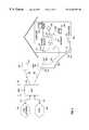
- FIG. 1illustrates a Fiber-to-the-Curb (FTTC) network in which various devices in the residence 190 are connected to the Public Switched Telecommunications Network (PSTN) 100 or Asynchronous Transfer Mode (ATM) network 110 .
- the devices in the residence 190can include telephone 194 , television (TV) 199 with a television set-top 198 , computer with Network Interface Card (NIC) 191 , and Premises Interface Device (PID) 196 connected to a telephone 194 .
- PSTNPublic Switched Telecommunications Network
- ATMAsynchronous Transfer Mode
- the FTTC network illustrated in FIG. 1works by connecting a Broadband Digital Terminal 130 to the PSTN 100 and ATM network 110 .
- the PSTN-BDT interface 103is specified by standards bodies, and in the US are specified by Bellcore specifications TR-TSY-000008, TR-NWT-000057 or GR-NWT-000303.
- the BDT 130can also receive special services signals from private or non-switched public networks.
- the physical interface to the PSTNis twisted wire pairs carrying DS-1 signals, or optical fibers carrying OC-3 optical signals.
- the interface to the ATM network-BDT interface 113can be realized using an OC-3 or OC-12c optical interfaces carrying ATM cells.
- BDT 130has two OC-12c broadcast ports, which receive signals carrying ATM cells, and one OC-12c interactive port which receives and transmits signals.
- An element management system (EMS) 151is connected to BDT 130 and forms part of the Element Management Layer (EML) which is used to provision services and equipment on the FTTC network, in the central office where the BDT 130 is located, in the field, or in the residences.
- EMLElement Management Layer
- the EMS 151is software based and can be run on a personal computer in which case it will support one BDT 130 and the associated access network equipment connected to it, or can be run on a workstation to support multiple BDTs and access networks.
- Broadband Network Units (BNUs) 140are located in the serving area and are connected to BDT 130 via optical fiber 160 .
- Digital signals in a format which is similar to the Synchronous Digital Hierarchy (SDH) formatare transmitted to and from each BNU 140 over optical fiber 160 at a rate of 155 Mb/s.
- optical fiber 160is a single-mode fiber and a dual wavelength transmission scheme is used to communicate between BNU 140 and BDT 130 .
- a single wavelength schemeis used in which low reflectivity components are used to permit transmission and reception on one fiber.
- a Telephony Interface Unit (TIU) 145 in BNU 140generates an analog Plain Old Telephony (POTs) signal which is transported to the residence 190 via a twisted wire pair drop cable 180 .
- NIDNetwork Interface Device
- TIU 145generates POTs signals for six residences 190 , each having a separate twisted wire pair drop cable 180 connected to BNU 140 .
- a Broadband Interface Unit (BIU) 150is located in BNU 140 and generates broadband signals which contain video, data and voice information.
- BIU 150modulates data onto an RF carrier and transmits the data over a coaxial drop cable 170 to a splitter 177 , and over inside coaxial wiring 171 to the devices in the residence 190 .
- each BNU 140is served by an BDT 130 .
- Each BNUserves 8 residences 190 .
- each BNU 140serves 16 residences 190 .
- each device connected to the inside coaxial wiring 171will require an interface sub-system which provides for the conversion of the signal from the format on the inside coaxial wiring 171 to the service interface required by the terminal equipment, which can be a telephone 194 , television 199 , computer, or other device.
- the PID 196extracts time division multiplexed information carried on the inside coaxial wiring 171 and generates a telephone signal compatible with telephone 194 .
- the television set-top 198converts digital video signals to analog signals compatible with TV 199 .
- the NIC cardgenerates a computer compatible signal.
- NID 183is located on the side of residence 190 at what is known in the industry as the network demarcation point.
- NID 183is a passive device whose principal functions are lightning protection and the ability to troubleshoot the network by allowing connection of a telephone 194 to the twisted wire pair drop cable 180 to determine if wiring problems exist on the inside twisted wire pairs 181 .
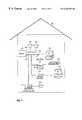
- FIG. 2illustrates the use of a gateway 200 to generate signals compatible with the devices in the home, which are connected to the gateway 200 via inside twisted wire pairs 181 or inside coaxial cable wiring 210 and a splitter 177 .
- the connection to the splitteris made using a gateway-splitter connection 210 , which in a preferred embodiment is coaxial cable.
- a direct connection to a televisioncan be made using a gateway-television connection 205 , which in a preferred embodiment is a four conductor cable carrying an S-video signal.
- the use of a gateway 200can reduce the number of devices required in the residence 190 to interface between the access network and the terminal equipment including television 199 , telephone 194 , and computer 193 .
- FIG. 3illustrates a FTTC network which relies on twisted wire pair drop cables 180 instead of coaxial drop cables 170 . This embodiment is preferable when it is cost prohibitive to install coaxial drop cables from BNUs 140 to residences 190 .
- a Universal Service Access Multiplexor (USAM) 340is located in the serving area, and is connected to BDT 130 via optical fiber 160 .
- An xDSL modem 350provides for the transmission of high-speed digital data over the twisted wire pair drop cable 180 to and from residence 190 .
- the term xDSLrefers to any one of the twisted wire pair digital subscriber loop transmission techniques including High Speed Digital Subscriber Loop, Asymmetric Digital Subscriber Loop, Very high speed Digital Subscriber Loop, Rate Adaptive Digital Subscriber Loop, or other similar twisted wire pair transmission techniques. Such transmission techniques are know to those skilled in the art.
- the xDSL modem 350contains the circuitry and software to generate a signal which can be transmitted over the twisted wire pair drop cable 180 , and which can receive high speed digital signals transmitted from gateway 200 or other devices connected to the subscriber network.
- NID/filter 360is used to separate the analog telephone signal from the digital signals.
- the majority of xDSL transmission techniquesleave the analog voice portion of the spectrum (from approximately 400 Hz to 4,000 Hz) undisturbed.
- the analog telephone signal, once separated from any digital data signals in the spectrum,is sent to telephone 194 over the inside twisted wire pairs 181 .
- the digital signals which are separated at the NID/filter 360are sent from a separate port on the NID/filter 360 to the gateway 200 .
- the gatewayserves as the interface to the devices in the residence 190 including the television 199 , the computer 193 , and additional telephone 194 .
- the central office configuration illustrated in FIG. 3includes a Universal Service Access Multiplexor Central Office Terminal (USAM COT) 324 connected to BDT 130 via a USAM COT-BDT connection 325 , which in a preferred embodiment is an STS 3 c signal transmitted over a twisted wire pair.
- the PSTN-USAM COT interface 303is one of the Bellcore specified interfaces including TR-TSY-000008, TR-NWT-000057 or TR-NWT-000303.
- the USAM COT 324has the same mechanical configuration as the USAM 340 in terms of power supplies and common control cards, but has line cards which support twisted wire pair interfaces to the PSTN (including DS-1 interfaces) and cards which support STS3c transmission over twisted wire pair for the USAM COT-BDT connection 325 .
- a Channel Bank (CB) 322is also used in the central office to connect specials networks 310 , comprised of signals from special private or public networks, to the access system via the specials networks-CB interface 313 .
- the CB-USAM COT connection 320are DS1 signals over twisted wire pairs.
- subscriber networkrefers in general to the connection between the BNU 140 and the devices or gateway 200 in the residence 190 or the connection between USAM 340 and the devices or the gateway in the residence 190 .
- the subscriber networkmay be comprised of coaxial cable and a splitter, twisted wire pairs, or any combination thereof.
- FIG. 2 and FIG. 3illustrate the gateway 200 located inside the living area of residence 190
- the gatewaycan be located in the basement, in the garage, in a wiring closet, on an outside wall of the residence 190 , in the attic, or in any of the living spaces.
- gateway 200will require a hardened enclosure and components which work over a larger temperature range than those used for a gateway located inside the residence 190 .
- Techniques for developing hardened enclosures and selecting temperature tolerant componentsare known to those skilled in the art.
- FIG. 4illustrates system architectures which have been used to provide high speed data services over existing twisted wire pair networks.
- a Host Digital Terminal (HDT) 422is connected to the PSTN 100 via twisted wire pairs 423 or optical fiber 160 .
- a Remote Terminal (RT) 430is connected to the HDT 422 via one or more optical fibers 160 .
- An analog POTs linecard 432is located in RT 432 and can provide analog telephone services over distances up to approximately 12,000 ft.
- an analog POTs linecard 432can be located directly in HDT 422 to provide analog telephone service to residences which are within 12,000 ft. of the telephone central office or remote structure.
- the architecture illustrated in FIG. 4is based on the provisioning of telephone service to subscribers.
- the Operational and Support Systems (OSS) 410 connected to HDT 422support basic and advanced telephone services, but does not support advanced high speed data services.
- OSSOperational and Support Systems
- FIG. 4illustrates the use of ADSL Channel Banks (ADSL CBs) 414 which are added to the network to provide high speed data services.
- An ADSL CB 414 with an xDSL modem 350can be added at the central office, and routes data signals into an Inter-Networking Unit (INU) 400 which takes data signals which are typically in the form of Internet Protocol (IP) packets and adapts them for transmission on the PSTN 100 in a PSTN compatible format such as frame relay, or switched multimegabit data service, or switched 56 data service.
- IPInternet Protocol
- OSS 410does not support high speed data services, a separate computer 193 is used to configure the INU 400 and provision data services.
- a fiber optic transceiver 351can be used in ADSL CB 414 to transmit high speed data signals over an optical fiber 160 to an ADSL CB 414 located in the local loop, remote from the central office.
- the ADSL CB 414 in the local loopcan be located near the RT 430 , and a line side diplex filter 418 is used to combine the analog telephony signal with the high speed data signal.
- the combined signalsare transmitted over twisted wire pair drop cable 180 to a subscriber side diplex filter 420 which separates the high speed data signal from the analog telephony signal.
- FIG. 4illustrates how high speed data can be transmitted from an ADSL CB in the telephone central office or remote office to a subscriber.
- the high speed data signals generated on XDSL modem 350are transmitted over twisted wire pair 423 to a line side diplex filter 418 which combines the high speed data signal with the analog telephony signal generated on the analog POTs linecard 432 .
- the combined signalsare transmitted over twisted wire pair drop cable 180 , and are received at the residence 190 , where a subscriber side diplex filter 420 separate the high speed data signal from the analog telephony signal.
- the high speed data signalsare transmitted over the inside twisted wire pairs 181 to devices in the residence, while the analog telephony signal is transmitted to telephone 194 .
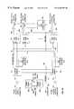
- FIG. 5illustrates one embodiment of the present invention for providing both high speed data and voice services from a single access network platform.
- a BDT 130is connected to an ATM network 110 via optical fibers 160 using the ATM network-BDT interfaces 113 , and simultaneously to the PSTN 100 via optical fibers 160 and twisted wire pairs 423 using the PSTN-BDT interfaces 103 previously described ATM/TDM description.
- An EMS 151which consists of a computer 193 and specialized EML software allows for the provisioning of traditional telephone as well as new services.
- OSS 410supports the provisioning of traditional telephone services, and as the OSS 410 is updated, EMS 151 allows for new services to be provisioned from the OSS 410 using flow-through provisioning.
- a USAM COT in the Central Office (USAM COT-CO) 530can be used to interface telephony signals from TR-TSY-000008, TR-NWT-000057 or GR-NWT-000303 interfaces provided by a public or private network to the BDT 130 .
- Thisis accomplished by receiving the signals in the TR-008, TR-057, and GR-303 formats transmitted over twisted wire pairs 423 at USAM COT-CO 530 , grooming and mulitplexing those signals as required, and transmitting them to BDT 130 over twisted wire pairs 423 using a STS 3 c format. In this way the BDT can be used to handle signals from additional networks.
- signals from other telecommunications services networkscan be routed to the BDT 130 through the use of a Channel Bank 322 which receives “specials” on twisted wire pairs 423 , multiplexes and grooms the signals, and transmits them on to USAM COT-CO over twisted wire pairs 423 .
- the USAM COT-COcan perform additional grooming and multiplexing as required, and transmit the signals to BDT 130 .
- an optical signal in an SDH type format at 155 Mb/scan be transmitted via optical fiber 160 to USAM ADSL in a Remote Terminal configuration (USAM ADSL-RT) 520 .
- a telephony/xDSL linecard 353 contained within the USAM ADSL-RT 520is used to generate both an xDSL signal as well as an analog telephony signal.
- the telephony/xDSL linecard 353generates an ADSL signal in addition to the analog telephony signal.
- the architecture for the telephony/xDSL linecard 353is described later in this specification and is illustrated in FIGS. 11A-12B.
- the combined telephony and high speed data signalsare transmitted over the twisted wire pair drop cable 180 to a subscriber side diplex filter 420 , which separates the separate the high speed data signal from the analog telephony signal.
- the high speed data signalsare transmitted over the inside twisted wire pairs 181 to devices in the residence, while the analog telephony signal is transmitted to telephone 194 .
- FIG. 5illustrates the use of a USAM ADSL in a Central Office configuration (USAM ADSL-CO) 510 .
- USAM ADSL-COCentral Office configuration
- high speed data and digitized telephony signalsare transmitted from BDT 130 to USAM ADSL-CO 510 over twisted wire pairs 423 .
- the USAM-ADSL-COcontains a telephony/xDSL linecard 353 which generates both an xDSL signal as well as an analog telephony signal.
- These signalsare transmitted to residence 190 , where there is a subscriber side diplex filter 420 which separates the high speed data signal from the analog telephony signal.
- the high speed data signalsare transmitted over the inside twisted wire pairs 181 to devices in the residence, while the analog telephony signal is transmitted to telephone 194 .
- FIG. 6illustrates an alternate embodiment, in which a USAM VDSL 620 is used to provide both the telephony and data signals.
- a telephony/xDSL linecard 353is used to generate both telephony and high speed data signals, but the high speed data signals are in a Very high speed Digital Subscriber Loop (VDSL)format as opposed to an Asymmetric Digital Subscriber Loop (ADSL) format.
- VDSLVery high speed Digital Subscriber Loop
- ADSLAsymmetric Digital Subscriber Loop
- VDSL transmissionsupports data rates up to approximately 26 Mb/s downstream to the residence 190 , and 5 Mb/s upstream from the residence 190 over distances not exceeding 3,000 ft.
- ADSLsupports data rates of up to 9 Mb/s downstream, and up to 640 kb/s upstream over distances of up to 9,000 ft.
- ADSL transmission techniquesit is possible to span distances up to 12,000 ft. with some reduction in the data rate.
- FIG. 6a system is illustrated in which signals are transmitted from a telephony/XDSL linecard 353 in USAM VDSL 620 over a twisted wire pair drop cable 180 to the subscriber side diplex filter 420 which separates the telephony and high speed data signals.
- the analog telephony signalsare transmitted from the subscriber side diplex filter 420 over inside twisted wire pairs 181 to telephone 194 .
- Data signalsare transmitted over inside coaxial wiring 171 to devices in residence 190 .
- FIG. 6illustrates an alternate embodiment in which digital signals are transmitted from a VDSL modem 354 in USAM VDSL 620 over a twisted wire pair drop cable 180 and are received at an Active Network Interface Device (ANID) 610 which generates an analog telephony signal for transmission over inside twisted wire pairs 181 to a telephone 194 .
- the VDSL modem 354 and ANID 610 architecturewhich can provide this functionality are described in greater detail in FIGS. 11A and 11B along with the corresponding text.
- FIG. 7illustrates an embodiment in which signals are received at residence 190 by a subscriber side diplex filter 420 which separates the analog telephony signal from the digital xDSL signal using filter techniques well understood by those skilled in the art. From the subscriber side diplex filter 420 the analog telephony signals are sent over a point-to-multi-point in-home network based on inside twisted wire pairs 181 and are received by telephones 194 .
- the digital high speed data signalis routed over a point-to-multipoint in-home network based on inside twisted wire pairs 181 to a variety of devices including a residential telephony interface unit 710 , a Local Area Network (LAN) unit 720 , a television set-top 198 , and a Network Interface Card (NIC) 750 .
- the residential telephony interface unit 710serves to separate the Time Division Multiplexed (TDM) data which contains telephony signals from the digital data stream on twisted wire pair 181 , and generate an analog telephony signal compatible with telephone 194 .
- Set-top 198extracts the ATM cells containing video and set-top specific data and presents that information on TV 199 .
- a remote keyboard 730can be used with set-top 198 to provide computer-type functionality.
- LAN unit 720extracts ATM cells which have the address of the LAN unit 720 and permit the computer 193 connected to the LAN unit 720 to be connected to the Internet or other intranets.
- NIC card 750interfaces computer 193 to external networks.
- FIG. 8illustrates an embodiment in which an ANID 610 receives the high speed digital data from a twisted wire pair drop cable 180 , and generates a coaxial cable compatible signal which is transmitted over inside coaxial cable wiring 171 to a splitter 177 .
- Splitter 177is of the type commonly used in homes today for the distribution of cable TV signals. The signals are routed from the splitter 177 over inside coaxial cable wiring 171 to a variety of devices including a Premises Interface Device (PID) 196 , a Local Area Network (LAN) unit 720 , a television set-top 198 , and a Network Interface Card (NIC) 750 .
- PIDPremises Interface Device
- LANLocal Area Network
- NICNetwork Interface Card
- FIG. 9illustrates the mechanical configuration of the Universal Service Access Multiplexor (USAM) 340 .
- the USAM 340can be rack mounted using brackets 910 , and has redundant USAM power supply plug-ins 930 .
- An air ramp 900is used to provide cooling.
- There are two common control cards, Common Control A 932 and Common Control B 934which interface to BDT 130 via optical fiber 160 .
- the bi-directional optical signals sent on optical fiber 160are in an SDH like format, at a rate of 155 Mb/s.
- USAM linecard plug-in units 920are used to provide telecommunications services to subscribers. These linecards interface to twisted wire pair drop cables 180 . In addition to linecards which interface to twisted wire pair drop cables 180 it is possible to have USAM linecard plug-in units 920 have fiber optic interfaces and which support optical transmission over fiber optic cable 160 . There are four general categories of linecard plug-in units 920 , including narrowband linecards, broadband linecards, VDSL linecards, and ADSL linecards.
- the narrowband linecardssupport legacy telephony services including POTs, coin phone services, T 1 services, ISDN services, and all of the existing special telecommunications services.
- Broadband linecardssupport Asynchronous Transfer Mode Universal Network Interfaces (UNIs). These UNI based broadband cards use an appropriate physical media which may be twisted wire pair, coaxial cable, optical fiber, or wireless connections.
- UNIsAsynchronous Transfer Mode Universal Network Interfaces
- VDSL linecardsare used to support residential broadband services over existing twisted wire pair drop cables 180 using VDSL transmission techniques, and can support transmission of traditional telephone signals either by generation of a POTs signal on the VDSL linecard and transmission with the digital VDSL signal in different portions of the spectrum, or by transmission of the telephone data in a digital form within the VDSL signal, with generation of the analog POTs signal occurring at the residence 190 .
- analog telephone signalscan be combined with the VDSL signal in a diplexor external to the linecard.
- the VDSL transmission technique usedis based on Quadrature Amplitude Modulation (QAM) transmission techniques in which data is sent in multiple levels in the I and Q channels, with the number of levels depending on the specific characteristics of the twisted wire pair drop cable 180 which is being used.
- QAMQuadrature Amplitude Modulation
- a single level phase inversion schemein both the I and Q channels
- QPSKQuadrature Phase Shift Keying
- 16-QAM or 64-QAM transmissioncan be used.
- ADSL linecardsare used to support residential broadband services using ADSL transmission techniques.
- ADSL transmission techniquesare based upon the use of Discrete MultiTone (DMT) transmission, or QAM techniques, including the Carrierless Amplitude Modulation technique, commonly referred to as CAP, which is a method for generation of QAM signals.
- Analog telephone signalscan be transmitted by the ADSL linecards in a manner similar to the VDSL linecards including generating the POTs signal on the ADSL linecard and combining it with the digital ADSL signal, generating the POTs signal externally and combining it with the ADSL signal, or generating the POTs signal at the residence 190 .
- the USAM 340supports 16 USAM linecard plug-ins 920 .
- there are 2 VDSL or ADSL circuits per USAM linecard plug-in 920resulting in 32 VDSL or ADSL circuits per USAM shelf.
- the USAM 340becomes a USAM ADSL-RT 520 or USAM ADSL-CO 510 as illustrated in FIG. 5 .
- the USAM 340becomes a USAM VDSL 620 as illustrated in FIG. 6 .
- USAM 340When USAM 340 is configured for POTs services, there are 6 circuits per linecard in one embodiment, resulting in 96 circuits per USAM shelf. In another embodiment, there are 12 circuits per POTs linecard, resulting in 192 POTs circuits per shelf.
- the USAM illustrated in FIG. 9represents a single shelf, but clearly it is possible to have multiple shelves for greater capacity.
- FIG. 10illustrates the architecture of USAM 340 , and shows how Common Control A 932 , and Common Control B 934 , are connected via optical fibers 160 to front access panel optical connectors 936 . These connectors are connected to optical fibers 160 which are in turn connected to BDT 130 .
- signalsare sent from Common Control A 932 to USAM linecard plug-ins 920 via a downstream common bus A 954 , and from Common Control B 934 to USAM linecard plug-ins 920 via a downstream common bus B 955 .
- Downstream common buses A and B 954 and 955respectively are point-to-multipoint buses, and all of the downstream payload is received at all of the USAM linecard plug-ins 920 .
- Upstream individual buses 952are used to transmit information from the USAM linecard plug-ins 920 to the Common Control A 932 and Common Control B 934 .
- a Front Access Panel (FAP) connector 938allows connection from the front of the USAM to an internal Front Access Panel (FAP) bus 940 which can be used for diagnostics.
- FAPFront Access Panel
- a Mechanized Loop Testing (MLT) bus 950is used to allow central office equipment to simulate a direct connection to a particular twisted wire pair drop cable 180 , in spite of the fact that there is actually an optical transmission system between the central office and the twisted wire pair drop cable 180 .
- the MLT bus 950in conjunction with circuitry on the POTs linecard allows central office equipment to determine the loop resistance and perform other key tests on a specific twisted wire pair drop cable 180 .
- the Tip and Ring (TR) connectors 956serve as the point of connectivity between the USAM linecard plug-ins 920 and the twisted wire pair drop cables 180 .
- the linecard-TR connector bus 960provides the internal connectivity between the USAM linecard plug-ins 920 and the TR connectors 956 .
- USAM linecard plug-ins 920which use optical media for transmission and reception are connected to a front access optical connector 936 via optical fiber 160 , or in an alternate embodiment the front access optical connector 936 is mounted directly on USAM linecard plug-in 920 .
- FIGS. 11A and 11Billustrate an embodiment in which VDSL signals are sent to the residence 190 from a VDSL linecard, along with a powering signal.
- the signalis received by a unit powered from the USAM which is capable of both deriving data for subsequent transmission in the residence 190 over inside twisted wire pairs 181 , or inside coaxial wiring 171 , as well as generating an analog telephony signal.
- FIG. 11Aa combined digital telephony and data xDSL line side modem 660 at the USAM 340 is illustrated and consists of a VDSL system Application Specific Integrated Circuit (ASIC) 654 which is connected to a USAM backplane bus connector 652 , which connects to the downstream common bus A 954 , downstream common bus B 955 , and upstream individual buses 952 .
- a line side VDSL modem 658is connected to the VDSL system ASIC 654 and generates a twisted wire pair compatible signal for transmission to the residence over the twisted wire pair drop cable 180 .
- a controller 662which can be any suitable microcontroller, is used to configure and program the VDSL system ASIC 654 .
- a line protection power insertion module 664permits the combining of the VDSL signal and the powering voltage, which in a preferred embodiment is ⁇ 90 V and in an alternate embodiment is ⁇ 130 V.
- a line side twisted wire pair with power interface 666is formed.
- the subscriber sideis illustrated in FIG. 11B, where a subscriber side twisted wire pair with power interface 667 is formed, and connects to a combined digital telephony and data xDSL subscriber side modem 661 via twisted wire pair drop cable 180 . Signals with power are received from the combined digital telephony and data xDSL line side modem 660 via the twisted wire pair drop cable 180 .
- line protection 670serves to separate the power and protect the subscriber side VDSL modem 674 .
- Subscriber side VDSL modem 674separates out the TDM signals containing telephony data and routes that data to a POTs circuit 676 .
- the POTs circuit 676generates an analog telephony signal which is routed to a twisted wire pair connector assembly 682 , which contains a derived first line POTs connector 690 , which in a preferred embodiment is an RJ- 11 jack.
- An optional POTs/ISDN circuit 678may be present and supports an additional POTs or ISDN line which can be connected via a derived second line POTs or ISDN connector 692 which is present in twisted wire pair connector assembly 682 .
- a coaxial modem 680also receives and transmits digital data to subscriber side VDSL modem 674 .
- Coaxial modem 680can take information from subscriber side VDSL modem 674 and generate a coaxial signal, which in a preferred embodiment is the Digital Audio Visual International Council (DAVIC) profile A type signal.
- the coaxial signal generated by coaxial modem 680is routed to a coaxial modem connector 694 , and subsequently to a combiner 696 .
- the combiner 696permits combining of the coaxial modem signal 680 with off-air broadcast television signals which come from an antenna or cable TV system connected to off-air connector 695 .
- the inside wiring network interface 697has both the analog POTs signals and digital data signals.
- FIGS. 11A and 11Bshow the subscriber side modem and line side modem as VDSL modems, ADSL or other types of modems can be used to realize the invention.
- the combined digital telephony and data xDSL subscriber side modem 661can also be located in gateway 200 , and as illustrated in FIG. 3, a variety of devices can be directly connected to the gateway using twisted wire pair, coaxial cable, or other types of wiring.
- FIGS. 12A and 12Billustrate an alternate embodiment for transmitting telephony signals along with xDSL data signals.
- the analog POTs signalis generated on a POTS circuit 676 which is located in a combined analog telephony and data xDSL line side modem 760 which is located in USAM 340 .
- the POTs circuit 676generates an analog telephone signal which is combined with a digital data signal from VDSL modem 658 in the line protection POTs filter 664 which serves as a line side diplex filter 418 .
- the combined analog telephony signal and digital data signalis present at the line side xDSL twisted wire pair with POTs interface 766 .
- a combined analog telephony and data xDSL subscriber side modem 761is used to receive the POTs and data signals.
- powering from the residence 190is used via an AC plug 779 and power supply 668 .
- An optional battery pack 777can be used to provide power to the combined analog telephony and data xDSL subscriber side modem 761 in the event the AC power in the residence 190 fails. Power from the AC plug 779 or optional battery pack 777 is transmitted to power supply 668 using conventional two conductor power cable or inside twisted wire pairs 181 .
- the combined analog telephony and data xDSL subscriber side modemfunctions for data according to the description for the data portion of the combined digital telephony and data xDSL line side modem 660 .
- the line protection POTs filter 770serves to separate the analog telephony signal from the digital data signal and serves to protect VDSL modem 674 and telephone 194 from excessive currents.
- the analog POTs signalis externally combined with the xDSL signal in the line side diplex filter 418 .
- the principal problems with this approachare that there are two twisted wire pairs from the cross connect frame (the connection location for twisted wire pair drop cables 180 coming from the telephone central office) two sets of lightning protection, and unknown characteristics in terms of the trip ring and other impulse noise on the POTs line which could be detrimental to the xDSL signal.
- the POTs circuit 676integrated onto the combined analog telephony and data xDSL line side modem it is possible to control the interference between the data signals generated by line side VDSL modem 658 and the analog POTs signal.
- This embodimentminimizes the amount of lightning protection required, as well as assuring that the impulse noise generated by the POTs circuit is characterized and controllable.
- a feeder pair from the central officeis liberated for reuse.
- FIGS. 12A and 12Bshow the subscriber side modem and line side modem as VDSL modems, ADSL or other types of modems can be used to realize the invention.
- the combined analog telephony and data xDSL subscriber side modem 761can also be located in gateway 200 , and as illustrated in FIG. 3, a variety of devices can be directly connected to the gateway using twisted wire pair, coaxial cable, or other types of wiring.
- a frame structure based on the Synchronous Digital Hierarchy (SDH) standardis utilized in which the most significant bit (bit 1 ) is sent first and the least significant bit (bit 8 ) is sent last.
- SDHSynchronous Digital Hierarchy
- a system specific datalink channelis sent within the SDH frame.
- the SDH frameitself has 2430 bytes in a 125 ⁇ s frame, divided into overhead areas, a 41 cell payload area and a 3 byte footer which is not used.
- the downstream ATM data(BDT 130 to BNU 140 or BDT 130 to USAM 340 ) is carried in a cell format illustrated in FIG. 13A, in which 4 system specific bytes form a downstream header 1004 which is added to a 53 byte ATM cell 1002 .
- the first two bytes in the header, 1006 and 1008are left unused, while the following two bytes 1010 and 1012 contain two BIU 150 routing tags, BIU 150 routing tag high byte 1010 , and BIU routing tag low byte 1012 .
- An ATM Virtual Path Indicator/Virtual Channel Indicator (VPI/VCI)and cell header field 1014are also present.
- a Header Error Control (HEC) field 1016contains an error correction code word which covers the header 1004 and the VPI/VCI cell header field 1014 .
- Upstream ATM datais carried in a cell format illustrated in FIG. 13B, in which 4 system specific bytes form an upstream header 1005 , which contains two unused bytes 1026 and 1028 , an ODU source ID byte 1030 , and a TCAM ID byte 1032 .
- An ATM VPI/VCI cell header field 1014is also present, as is an HEC field 1016 .
- An ATM cell 1002 of 53 bytescontains the ATM data.
- Time Division Multiplex (TDM) datais carried in both directions on optical fiber 160 (BDT 130 to BNU 140 or BDT 130 to USAM 340 ) as well as on the twisted wire pair BDT-USAM link 226 in a cell format of 57 bytes.
- the TDM cellconsists of two segments of 28 bytes and a TDM cell reserved byte, as illustrated in FIG. 14A, in which a 57 byte TDM cell is comprised of a TDM cell reserved byte 1102 , a first TDM segment 1104 , and a second TDM segment 1106 .
- the individual DSOs within the TDM segmentsare mapped into three TDM blocks of nine bytes each.
- a reserved segment byte 1108precedes a first TDM block 1110 , a second TDM block 1112 , and a third TDM block 1114 .
- VT 1.5An asynchronous virtual tributary (VT 1.5) can be transported in a TDM segment as illustrated in FIG. 14C by sending one reserved VT 1.5 byte 1116 followed by a 27 byte VT1.5 field 1118 .
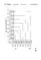
- FIG. 15The particular mapping of DSOs in a TDM block is illustrated in FIG. 15, where eight DSO channels are transported in bytes 2 - 9 ( 1204 , 1206 , 1208 , 1210 , 1212 , 1214 , 1216 , and 1218 respectively).
- the signaling information for each DS 0is transported in a signaling byte.
- the signaling byteis the first byte in the nine byte sequence which forms a frame, and each of eight frames carries the signaling information for one DS 0 channel.
- channel 1 signaling byte 1214appears as the first byte of frame 1
- channel 2 signaling byte 1216as byte 1 of frame 2
- Channel 3 - 8 signaling bytes1218 , 1220 , 1222 , 1224 , 1226 , 1228 respectively) appear in the first byte of frames 3 - 8 respectively.
- the destinationcan be a BIU 150 , USAM linecard plug-in 920 , ANID 610 , PID 196 , set-top 198 , computer with NIC card 191 , telephony interface unit 710 , LAN unit 720 , or gateway 200 .
- the mapping of cellsoccurs at both the network side, where cells are formed from the data received from ATM network 110 , and from PSTN 100 , and at the subscriber side, where the different devices generate TDM voice information or high speed data.
- a PID 196would generate TDM information and a set-top 198 or computer with NIC card 191 would generate high speed data.
- the devices in the residence or the gateway 200would map the information into ATM cells for transmission on the Unified Access Platform.
- mapping of TDM information into ATM cells, and the formation of the headersis performed in one or more Application Specific Integrated Circuits (ASICs). Methods for the implementation of such ASICs are well known to those skilled in the art. In an alternate embodiment the mapping of TDM and high speed data information can be performed in software.
- ASICsApplication Specific Integrated Circuits
- the mapping of TDM information into cellsallows for the efficient routing of those cells to the individual Optical Distribution Units (ODUs) in the BDT which generate and receive optical signals from BNUs 140 or USAMs 340 .
- ODUsOptical Distribution Units
- a BDT common control cardcontrols the routing of cells to the individual ODUs in BDT 130 .
- ATM cells in BDT 130 and over optical fiber 160allows voice and data information to be simultaneously routed from one BDT 130 to BNUs 140 , USAM ADSL-RT 520 , USAM ADSL-CO 510 , and USAM VDSLs 620 , where traditional analog telephone signals can be generated along with high speed data signals. Because the transmission technique and media for transmission of high speed data signals will vary from installation to installation, it is important to be able to support the various xDSL and coaxial drop cable networks from one Unified Access Platform.
Landscapes
- Engineering & Computer Science (AREA)
- Computer Networks & Wireless Communication (AREA)
- Signal Processing (AREA)
- Data Exchanges In Wide-Area Networks (AREA)
- Telephonic Communication Services (AREA)
- Interface Circuits In Exchanges (AREA)
Abstract
Description
Claims (47)
Priority Applications (11)
| Application Number | Priority Date | Filing Date | Title |
|---|---|---|---|
| US08/905,775US6282189B1 (en) | 1997-04-14 | 1997-08-04 | Unified access platform for simultaneously delivering voice and cell-based services |
| BR9808530-1ABR9808530A (en) | 1997-04-14 | 1998-04-13 | Process and apparatus for simultaneously providing high-speed data and telephony services in a telecommunications system |
| NZ500026ANZ500026A (en) | 1997-04-14 | 1998-04-13 | Unified system for providing telephone and high speed data services on local loop |
| AU71117/98AAU744631B2 (en) | 1997-04-14 | 1998-04-13 | Unified access platform for simultaneously delivering voice and cell-based services |
| JP54414498AJP3620601B2 (en) | 1997-04-14 | 1998-04-13 | Integrated access platform |
| PCT/US1998/007347WO1998047251A2 (en) | 1997-04-14 | 1998-04-13 | Unified access platform distributing atm cells and telephony signals to subscriber premises over twisted wire pairs |
| CA002289480ACA2289480C (en) | 1997-04-14 | 1998-04-13 | Unified access platform distributing atm cells and telephony signals to subscriber premises over twisted wire pairs |
| KR1019997009455AKR20010006369A (en) | 1997-04-14 | 1998-04-13 | Unified access platform |
| EP98918136AEP0976210A4 (en) | 1997-04-14 | 1998-04-13 | Unified access platform |
| TW087105638ATW493327B (en) | 1997-04-14 | 1998-04-14 | Method and system for providing telephony and cell-based services, and for delivering voice and cell-based services |
| US09/231,665US6208637B1 (en) | 1997-04-14 | 1999-01-15 | Method and apparatus for the generation of analog telephone signals in digital subscriber line access systems |
Applications Claiming Priority (2)
| Application Number | Priority Date | Filing Date | Title |
|---|---|---|---|
| US4381197P | 1997-04-14 | 1997-04-14 | |
| US08/905,775US6282189B1 (en) | 1997-04-14 | 1997-08-04 | Unified access platform for simultaneously delivering voice and cell-based services |
Related Child Applications (1)
| Application Number | Title | Priority Date | Filing Date |
|---|---|---|---|
| US09/231,665Continuation-In-PartUS6208637B1 (en) | 1997-04-14 | 1999-01-15 | Method and apparatus for the generation of analog telephone signals in digital subscriber line access systems |
Publications (1)
| Publication Number | Publication Date |
|---|---|
| US6282189B1true US6282189B1 (en) | 2001-08-28 |
Family
ID=26720839
Family Applications (1)
| Application Number | Title | Priority Date | Filing Date |
|---|---|---|---|
| US08/905,775Expired - LifetimeUS6282189B1 (en) | 1997-04-14 | 1997-08-04 | Unified access platform for simultaneously delivering voice and cell-based services |
Country Status (10)
| Country | Link |
|---|---|
| US (1) | US6282189B1 (en) |
| EP (1) | EP0976210A4 (en) |
| JP (1) | JP3620601B2 (en) |
| KR (1) | KR20010006369A (en) |
| AU (1) | AU744631B2 (en) |
| BR (1) | BR9808530A (en) |
| CA (1) | CA2289480C (en) |
| NZ (1) | NZ500026A (en) |
| TW (1) | TW493327B (en) |
| WO (1) | WO1998047251A2 (en) |
Cited By (67)
| Publication number | Priority date | Publication date | Assignee | Title |
|---|---|---|---|---|
| US20010030950A1 (en)* | 2000-01-31 | 2001-10-18 | Chen Steven Chien-Young | Broadband communications access device |
| US20010048679A1 (en)* | 1997-07-10 | 2001-12-06 | Alcatel | Housing for connection to both broadband and narrowband networks as a shelf in a telecommunications rack |
| US6404763B1 (en)* | 2000-02-11 | 2002-06-11 | General Bandwidth Inc. | System and method for communicating telecommunication information between network equipment and a plurality of local loop circuits |
| US20030043785A1 (en)* | 2001-08-23 | 2003-03-06 | Ming-Kang Liu | Configurable digital subscriber loop access and end-to-end data and analog voice connection system |
| US20030128983A1 (en)* | 1999-05-11 | 2003-07-10 | Buabbud George H. | Digital RF return over fiber |
| US6608837B1 (en)* | 1998-10-08 | 2003-08-19 | Qwest Communications International, Inc. | Data carousel franchise provisioning |
| US6640101B1 (en)* | 1999-08-06 | 2003-10-28 | Bellsouth Intellectual Property Corporation | Remote transmission testing and monitoring to a cell site in a cellular communications network |
| US6647024B1 (en)* | 1999-05-07 | 2003-11-11 | Lucent Technologies Inc. | System and method for an all digital communication system with a life line |
| US6650628B1 (en)* | 1998-07-09 | 2003-11-18 | Alcatel Canada Inc. | Combining QAM and QPSK to optimize license capacity in cellular, multipoint wireless access systems |
| US6658049B1 (en)* | 1999-01-12 | 2003-12-02 | Cisco Technology, Inc. | xDSL repeater system and method |
| US6665299B1 (en)* | 1998-01-14 | 2003-12-16 | At&T Corp. | Method and system for telephony and high speed data access on a broadband access network |
| US6700901B1 (en)* | 1998-11-09 | 2004-03-02 | Siemens Information & Communication Networks, Inc. | System and method for digital telephones on H.323 networks |
| US6768736B1 (en) | 1998-12-30 | 2004-07-27 | Nortel Networks Limited | Using an ATM switch to grow the capacity of a switching stage |
| US20040151289A1 (en)* | 2003-01-31 | 2004-08-05 | Qwest Communications International Inc (Patent Prosecution) | Packet network interface device and systems and methods for its use |
| US20040151290A1 (en)* | 2003-01-31 | 2004-08-05 | Qwest Communications International Inc. | Network interface device having virtual private network capability |
| US20040151168A1 (en)* | 2003-01-31 | 2004-08-05 | Qwest Communications International Inc (Patent Prosecution) | Configurable network interface device and systems and methods for its use |
| US20040150748A1 (en)* | 2003-01-31 | 2004-08-05 | Qwest Communications International Inc. | Systems and methods for providing and displaying picture-in-picture signals |
| US20040150749A1 (en)* | 2003-01-31 | 2004-08-05 | Qwest Communications International Inc. | Systems and methods for displaying data over video |
| US20040151161A1 (en)* | 2003-01-31 | 2004-08-05 | Qwest Communications International Inc. | Systems and methods for providing application services |
| US20040153577A1 (en)* | 2003-01-31 | 2004-08-05 | Qwest Communications International Inc. | Method for replacing a network interface device |
| US20040150518A1 (en)* | 2003-01-31 | 2004-08-05 | Qwest Communications International Inc. | Methods, systems and apparatus for providing urgent public information |
| US20040153670A1 (en)* | 2003-01-31 | 2004-08-05 | Qwest Communications International Inc | Systems and methods for controlled transmittance in a telecommunication system |
| US6778538B2 (en) | 1998-12-30 | 2004-08-17 | Nortel Networks Limited | Virtual junctors |
| US20040163128A1 (en)* | 2003-01-31 | 2004-08-19 | Qwest Communications International Inc. | Fiber optic internet protocol network interface device and methods and systems for using the same |
| US20040168199A1 (en)* | 2003-01-31 | 2004-08-26 | Qwest Communications International Inc. | DOCSIS network interface device and methods and systems for using the same |
| US20040172657A1 (en)* | 2003-01-31 | 2004-09-02 | Qwest Communications International Inc | ADSL/DBS network interface device and methods and systems for using the same |
| US6788703B2 (en)* | 1998-12-30 | 2004-09-07 | Nortel Networks Limited | DS0 on ATM, mapping and handling |
| US20040176085A1 (en)* | 2003-01-31 | 2004-09-09 | Qwest Communications International Inc (Patent Prosecution) | Systems, methods and apparatus for providing a plurality of telecommunication services |
| US20040177163A1 (en)* | 2003-01-31 | 2004-09-09 | Qwest Communications International Inc. | Systems and methods for integrating microservers with a network interface device |
| US6804229B2 (en) | 1998-12-30 | 2004-10-12 | Nortel Networks Limited | Multiple node network architecture |
| US20040264687A1 (en)* | 2003-06-30 | 2004-12-30 | Qwest Communications International Inc. | System and method for cooling of network interface device |
| US20050008131A1 (en)* | 2003-01-31 | 2005-01-13 | Qwest Communications International Inc. | Environmentally-controlled network interface device and methods |
| US6848116B1 (en)* | 1999-01-13 | 2005-01-25 | Itt Manufacturing Enterprises, Inc. | Method and apparatus for on-demand video program access control using integrated out-of-band signaling for channel selection |
| US20050018653A1 (en)* | 2003-07-22 | 2005-01-27 | Qwest Communications International Inc (Patent Prosecution) | Personal communication service network interface device |
| US20050022007A1 (en)* | 2003-06-02 | 2005-01-27 | Qwest Communications International Inc | Systems and methods for distributing content objects in a telecommunication system |
| US20050030977A1 (en)* | 2003-01-31 | 2005-02-10 | Qwest Communications International Inc. | Alert gateway, systems and methods |
| US20050041787A1 (en)* | 2003-08-19 | 2005-02-24 | Qwest Communications International Inc (Patent Prosecution) | Advanced call screening appliance |
| US6879591B1 (en)* | 1998-11-30 | 2005-04-12 | Nec Corporation | Transferring voice over an asymmetric digital subscriber line |
| US6885661B1 (en) | 1998-12-30 | 2005-04-26 | Nortel Networks Limited | Private branch exchange built using an ATM Network |
| US6886181B1 (en)* | 2000-07-07 | 2005-04-26 | Critical Telecom Corp. | Extended distribution of ADSL signals |
| US20050089052A1 (en)* | 2000-01-31 | 2005-04-28 | 3E Technologies International, Inc. | Broadband communications access device |
| US20050144645A1 (en)* | 2003-01-31 | 2005-06-30 | Qwest Communications International Inc . | Methods, systems and apparatus for providing video transmissions over multiple media |
| US6954461B1 (en)* | 1998-12-22 | 2005-10-11 | Nortel Networks Limited | Communications network |
| US7012899B1 (en)* | 2000-09-22 | 2006-03-14 | The Directv Group, Inc. | System and method for auto-configuration of a DSL modem |
| US20060117364A1 (en)* | 2000-02-06 | 2006-06-01 | Roman Vitenberg | Digital subscriber line communication system |
| US7099349B1 (en)* | 1999-03-10 | 2006-08-29 | Qwest Communications International Inc. | xDSL-based communication system |
| US20070030856A1 (en)* | 2005-08-08 | 2007-02-08 | Cooke Stephen P | Shared DSL Network and Deployment Method |
| US7187418B2 (en) | 2003-01-31 | 2007-03-06 | Qwest Communications International, Inc. | Systems and methods for delivering picture-in-picture signals at diverse compressions and bandwidths |
| US7187686B1 (en)* | 1996-11-01 | 2007-03-06 | Sbc Properties, B.P. | Telecommunication system, method and subscriber unit for use therein |
| US20070127454A1 (en)* | 2001-04-24 | 2007-06-07 | General Bandwidth Inc. | System and Method for Providing Lifeline Telecommunication Service |
| US7264590B2 (en) | 2003-01-31 | 2007-09-04 | Qwest Communications International Inc. | Real-time medical monitoring application with a network interface device |
| US20090036159A1 (en)* | 2000-01-31 | 2009-02-05 | 3E Technologies International, Inc. | Broadband communications access device |
| US20090060151A1 (en)* | 1999-07-20 | 2009-03-05 | Serconet, Ltd | Network for telephony and data communication |
| US20090092242A1 (en)* | 2007-10-04 | 2009-04-09 | Genesis Technical Systems Corp. | Remote powering of dsl adms |
| US7525959B2 (en) | 1997-11-10 | 2009-04-28 | At&T Intellectual Property I, L.P. | System and method for distributing voice and data information over wireless and wireline networks |
| US7657010B1 (en)* | 2003-02-21 | 2010-02-02 | Sprint Communications Company L.P. | System and method for establishing a high speed non-switched data connection |
| US7734282B2 (en) | 2003-08-28 | 2010-06-08 | Qwest Communications International Inc | System and method for provisioning customer premises equipment |
| US20100254363A1 (en)* | 2000-04-19 | 2010-10-07 | Mosaid Technologies Incorporated | Network combining wired and non-wired segments |
| US7852874B2 (en) | 1998-07-28 | 2010-12-14 | Mosaid Technologies Incorporated | Local area network of serial intelligent cells |
| US8064369B1 (en)* | 1998-12-01 | 2011-11-22 | Qwest Communications International Inc | System and method for increasing distribution distance of XDSL type signals |
| US8112449B2 (en) | 2003-08-01 | 2012-02-07 | Qwest Communications International Inc. | Systems and methods for implementing a content object access point |
| US8490129B2 (en) | 2003-01-31 | 2013-07-16 | Qwest Communications International Inc. | Methods, systems and apparatus for selectively distributing urgent public information |
| US8582598B2 (en) | 1999-07-07 | 2013-11-12 | Mosaid Technologies Incorporated | Local area network for distributing data communication, sensing and control signals |
| US10136470B2 (en) | 2012-07-05 | 2018-11-20 | Centurylink Intellectual Property Llc | Multi-service provider wireless access point |
| US10142023B2 (en) | 2003-01-31 | 2018-11-27 | Centurylink Intellectual Property Llc | Antenna system and methods for wireless optical network termination |
| US10462846B2 (en) | 2012-07-05 | 2019-10-29 | Centurylink Intellectual Property Llc | Multi-service provider wireless access point |
| US20220368408A1 (en)* | 2021-05-12 | 2022-11-17 | T-Mobile Usa, Inc. | Optimizing Use of Existing Telecommunication Infrastructure for Wireless Connectivity |
Families Citing this family (11)
| Publication number | Priority date | Publication date | Assignee | Title |
|---|---|---|---|---|
| US6567981B1 (en) | 1998-08-03 | 2003-05-20 | Elysium Broadband Inc. | Audio/video signal redistribution system |
| US6542465B1 (en) | 1999-05-28 | 2003-04-01 | 3Com Corporation | Method for flow control in asymmetric digital subscriber line devices |
| KR100506233B1 (en)* | 1999-10-27 | 2005-09-02 | 삼성전자주식회사 | Home network system in asymmetric digital subscriber line system |
| US6775268B1 (en) | 2000-03-03 | 2004-08-10 | 3Com Corporation | Method and system for mapping packet service categories to asymmetric digital subscriber line latency paths |
| US6396837B1 (en) | 2000-03-03 | 2002-05-28 | 3Com Corporation | Method and system for mapping virtual connections to asymmetric digital subscriber line latency paths |
| AU4443701A (en)* | 2000-03-30 | 2001-10-08 | Adc Telecommunications Israel Ltd. | Integrated adsl interface with tdm mapping |
| CN1448027A (en)* | 2000-08-21 | 2003-10-08 | 库克斯媒体有限公司 | Capacity scaling and functional element redistribution within in-building coax cable internet access system |
| WO2004038974A2 (en) | 2000-08-30 | 2004-05-06 | Polycom, Inc. | Measuring sample arrival rates on an atm network |
| US7116637B2 (en) | 2000-09-06 | 2006-10-03 | Verso Technologies, Inc. | System and method for diagnosing a POTS port |
| JP2007150618A (en)* | 2005-11-25 | 2007-06-14 | Matsushita Electric Works Ltd | Wiring system for floor, and wiring system for building using same |
| JP2009071719A (en)* | 2007-09-14 | 2009-04-02 | Nec Corp | Communication device, communication system, control method, and control program |
Citations (8)
| Publication number | Priority date | Publication date | Assignee | Title |
|---|---|---|---|---|
| US4441180A (en)* | 1979-06-01 | 1984-04-03 | Licentia Patent-Verwaltungs-Gmbh | Service integrated communication transmission and interchange system |
| US4686667A (en) | 1984-02-03 | 1987-08-11 | Standard Electrik Lorenz Ag | Broadband integrated subscriber loop system |
| US4819226A (en) | 1987-11-10 | 1989-04-04 | Bell Communications Research, Inc. | Framer circuit for use in a DTDM network |
| US4893306A (en) | 1987-11-10 | 1990-01-09 | Bell Communications Research, Inc. | Method and apparatus for multiplexing circuit and packet traffic |
| US5534912A (en)* | 1994-04-26 | 1996-07-09 | Bell Atlantic Network Services, Inc. | Extended range video on demand distribution system |
| US5610922A (en)* | 1995-03-20 | 1997-03-11 | Raychem Corporation | Voice plus 4-wire DDS multiplexer |
| US5613190A (en)* | 1995-05-01 | 1997-03-18 | Bell Atlantic Network Services, Inc. | Customer premise wireless distribution of audio-video, control signals and voice |
| US5668857A (en)* | 1996-03-29 | 1997-09-16 | Netspeed, Inc. | Communication server apparatus and method |
Family Cites Families (5)
| Publication number | Priority date | Publication date | Assignee | Title |
|---|---|---|---|---|
| US5341374A (en)* | 1991-03-01 | 1994-08-23 | Trilan Systems Corporation | Communication network integrating voice data and video with distributed call processing |
| IL108402A (en)* | 1994-01-21 | 1999-04-11 | News Datacom Ltd | Integrated telephone and cable communication networks |
| US5541917A (en)* | 1994-09-12 | 1996-07-30 | Bell Atlantic | Video and TELCO network control functionality |
| US5592477A (en)* | 1994-09-12 | 1997-01-07 | Bell Atlantic Network Services, Inc. | Video and TELCO network control functionality |
| US5570355A (en)* | 1994-11-17 | 1996-10-29 | Lucent Technologies Inc. | Method and apparatus enabling synchronous transfer mode and packet mode access for multiple services on a broadband communication network |
- 1997
- 1997-08-04USUS08/905,775patent/US6282189B1/ennot_activeExpired - Lifetime
- 1998
- 1998-04-13CACA002289480Apatent/CA2289480C/ennot_activeExpired - Lifetime
- 1998-04-13EPEP98918136Apatent/EP0976210A4/ennot_activeWithdrawn
- 1998-04-13WOPCT/US1998/007347patent/WO1998047251A2/ennot_activeApplication Discontinuation
- 1998-04-13BRBR9808530-1Apatent/BR9808530A/ennot_activeApplication Discontinuation
- 1998-04-13NZNZ500026Apatent/NZ500026A/enunknown
- 1998-04-13AUAU71117/98Apatent/AU744631B2/ennot_activeCeased
- 1998-04-13KRKR1019997009455Apatent/KR20010006369A/ennot_activeCeased
- 1998-04-13JPJP54414498Apatent/JP3620601B2/ennot_activeExpired - Fee Related
- 1998-04-14TWTW087105638Apatent/TW493327B/ennot_activeIP Right Cessation
Patent Citations (8)
| Publication number | Priority date | Publication date | Assignee | Title |
|---|---|---|---|---|
| US4441180A (en)* | 1979-06-01 | 1984-04-03 | Licentia Patent-Verwaltungs-Gmbh | Service integrated communication transmission and interchange system |
| US4686667A (en) | 1984-02-03 | 1987-08-11 | Standard Electrik Lorenz Ag | Broadband integrated subscriber loop system |
| US4819226A (en) | 1987-11-10 | 1989-04-04 | Bell Communications Research, Inc. | Framer circuit for use in a DTDM network |
| US4893306A (en) | 1987-11-10 | 1990-01-09 | Bell Communications Research, Inc. | Method and apparatus for multiplexing circuit and packet traffic |
| US5534912A (en)* | 1994-04-26 | 1996-07-09 | Bell Atlantic Network Services, Inc. | Extended range video on demand distribution system |
| US5610922A (en)* | 1995-03-20 | 1997-03-11 | Raychem Corporation | Voice plus 4-wire DDS multiplexer |
| US5613190A (en)* | 1995-05-01 | 1997-03-18 | Bell Atlantic Network Services, Inc. | Customer premise wireless distribution of audio-video, control signals and voice |
| US5668857A (en)* | 1996-03-29 | 1997-09-16 | Netspeed, Inc. | Communication server apparatus and method |
Non-Patent Citations (6)
| Title |
|---|
| Arpad G. Toth, Ettore Colombini, Peter J. MacLaren, Robert K. Yates; "Fiber in the Local Exchange Network: A Planning Overview"; Proceedings of the National Communications Forum; vol. XXXIX, Oct. 7-9, 1985. |
| Clemens Baack, Peter Heuer: "Architecture of Broad-Band Communications Systems"; IEEE Journal on Selected Areas in Communications; vol. SAC-4, No. 4, Jul. 1986. 542-550. |
| D.V. Batorsky, D.R. Spears and A.R. Tedesco: "The Evolution of Broadband Network Architectures"; published in the conference record of the IEEE Global Telecommunications Conference and Exhibition, Nov. 28-Dec. 1, 1988, 367-373. |
| Hans, J. Matt, Kurt Fussgaenger: "Integrated Broad-Band Communication Using Optical Networks-Results of an Experimental Study"; IEEE Transactions on Communications; vol. Com-29, No. 6, Jun. 1981, 868-885. |
| Hans, J. Matt, Kurt Fussgaenger: "Integrated Broad-Band Communication Using Optical Networks—Results of an Experimental Study"; IEEE Transactions on Communications; vol. Com-29, No. 6, Jun. 1981, 868-885. |
| J. Stern, J.A. Quayle, S.A. Cooper: "Full Services Access Network Requirements Specification"; Published as a specification of the Full Services Network Working Group; Release Date Feb. 25, 1997, 1-44. |
Cited By (136)
| Publication number | Priority date | Publication date | Assignee | Title |
|---|---|---|---|---|
| US7187686B1 (en)* | 1996-11-01 | 2007-03-06 | Sbc Properties, B.P. | Telecommunication system, method and subscriber unit for use therein |
| US20010048679A1 (en)* | 1997-07-10 | 2001-12-06 | Alcatel | Housing for connection to both broadband and narrowband networks as a shelf in a telecommunications rack |
| US7042900B2 (en)* | 1997-07-10 | 2006-05-09 | Alcatel | Housing for connection to both broadband and narrowband networks as a shelf in a telecommunications rack |
| US7525959B2 (en) | 1997-11-10 | 2009-04-28 | At&T Intellectual Property I, L.P. | System and method for distributing voice and data information over wireless and wireline networks |
| US8594115B2 (en) | 1997-11-10 | 2013-11-26 | At&T Intellectual Property I, L.P. | Distributing voice and data information over wireless and wireline networks |
| US7995601B2 (en) | 1997-11-10 | 2011-08-09 | At&T Intellectual Property I, L.P. | System and method for distributing voice and data information over wireless and wireline networks |
| US6665299B1 (en)* | 1998-01-14 | 2003-12-16 | At&T Corp. | Method and system for telephony and high speed data access on a broadband access network |
| US8107479B2 (en)* | 1998-01-14 | 2012-01-31 | At&T Intellectual Property Ii, L.P. | Method and system for telephony and high-speed data access on a broadband access network |
| US20050041797A1 (en)* | 1998-01-14 | 2005-02-24 | Bellovin Steven Michael | Method and system for telephony and high-speed data access on a broadband access network |
| US6650628B1 (en)* | 1998-07-09 | 2003-11-18 | Alcatel Canada Inc. | Combining QAM and QPSK to optimize license capacity in cellular, multipoint wireless access systems |
| US8885659B2 (en) | 1998-07-28 | 2014-11-11 | Conversant Intellectual Property Management Incorporated | Local area network of serial intelligent cells |
| US8885660B2 (en) | 1998-07-28 | 2014-11-11 | Conversant Intellectual Property Management Incorporated | Local area network of serial intelligent cells |
| US7978726B2 (en) | 1998-07-28 | 2011-07-12 | Mosaid Technologies Incorporated | Local area network of serial intelligent cells |
| US7852874B2 (en) | 1998-07-28 | 2010-12-14 | Mosaid Technologies Incorporated | Local area network of serial intelligent cells |
| US8325636B2 (en) | 1998-07-28 | 2012-12-04 | Mosaid Technologies Incorporated | Local area network of serial intelligent cells |
| US8867523B2 (en) | 1998-07-28 | 2014-10-21 | Conversant Intellectual Property Management Incorporated | Local area network of serial intelligent cells |
| US8270430B2 (en) | 1998-07-28 | 2012-09-18 | Mosaid Technologies Incorporated | Local area network of serial intelligent cells |
| US7965735B2 (en) | 1998-07-28 | 2011-06-21 | Mosaid Technologies Incorporated | Local area network of serial intelligent cells |
| US8908673B2 (en) | 1998-07-28 | 2014-12-09 | Conversant Intellectual Property Management Incorporated | Local area network of serial intelligent cells |
| US6608837B1 (en)* | 1998-10-08 | 2003-08-19 | Qwest Communications International, Inc. | Data carousel franchise provisioning |
| US6700901B1 (en)* | 1998-11-09 | 2004-03-02 | Siemens Information & Communication Networks, Inc. | System and method for digital telephones on H.323 networks |
| US6879591B1 (en)* | 1998-11-30 | 2005-04-12 | Nec Corporation | Transferring voice over an asymmetric digital subscriber line |
| US8064369B1 (en)* | 1998-12-01 | 2011-11-22 | Qwest Communications International Inc | System and method for increasing distribution distance of XDSL type signals |
| US6954461B1 (en)* | 1998-12-22 | 2005-10-11 | Nortel Networks Limited | Communications network |
| US6804229B2 (en) | 1998-12-30 | 2004-10-12 | Nortel Networks Limited | Multiple node network architecture |
| US6885661B1 (en) | 1998-12-30 | 2005-04-26 | Nortel Networks Limited | Private branch exchange built using an ATM Network |
| US6778538B2 (en) | 1998-12-30 | 2004-08-17 | Nortel Networks Limited | Virtual junctors |
| US6768736B1 (en) | 1998-12-30 | 2004-07-27 | Nortel Networks Limited | Using an ATM switch to grow the capacity of a switching stage |
| US6788703B2 (en)* | 1998-12-30 | 2004-09-07 | Nortel Networks Limited | DS0 on ATM, mapping and handling |
| US6658049B1 (en)* | 1999-01-12 | 2003-12-02 | Cisco Technology, Inc. | xDSL repeater system and method |
| US6848116B1 (en)* | 1999-01-13 | 2005-01-25 | Itt Manufacturing Enterprises, Inc. | Method and apparatus for on-demand video program access control using integrated out-of-band signaling for channel selection |
| US7099349B1 (en)* | 1999-03-10 | 2006-08-29 | Qwest Communications International Inc. | xDSL-based communication system |
| US6647024B1 (en)* | 1999-05-07 | 2003-11-11 | Lucent Technologies Inc. | System and method for an all digital communication system with a life line |
| US20030128983A1 (en)* | 1999-05-11 | 2003-07-10 | Buabbud George H. | Digital RF return over fiber |
| US8582598B2 (en) | 1999-07-07 | 2013-11-12 | Mosaid Technologies Incorporated | Local area network for distributing data communication, sensing and control signals |
| US8929523B2 (en) | 1999-07-20 | 2015-01-06 | Conversant Intellectual Property Management Inc. | Network for telephony and data communication |
| US20090060151A1 (en)* | 1999-07-20 | 2009-03-05 | Serconet, Ltd | Network for telephony and data communication |
| US6640101B1 (en)* | 1999-08-06 | 2003-10-28 | Bellsouth Intellectual Property Corporation | Remote transmission testing and monitoring to a cell site in a cellular communications network |
| US20090252043A1 (en)* | 1999-08-06 | 2009-10-08 | At&T Intellectual Property I., L.P. F/K/A Bellsouth Intellectual Property Corporation | Remote testing and monitoring to a cell site in a cellular communication network |
| US7567519B1 (en) | 1999-08-06 | 2009-07-28 | At&T Intellectual Property, I, L.P. | Remote testing and monitoring to a cell site in a cellular communications network |
| US9007925B2 (en) | 1999-08-06 | 2015-04-14 | At&T Intellectual Property I, L.P. | Remote testing and monitoring to a cell site in a cellular communications network |
| US8085677B2 (en) | 1999-08-06 | 2011-12-27 | At&T Intellectual Property I. L.P. | Remote testing and monitoring to a cell site in a cellular communication network |
| US8654657B2 (en) | 1999-08-06 | 2014-02-18 | At&T Intellectual Property I, L.P. | Remote testing and monitoring to a cell site in a cellular communications network |
| US20050089052A1 (en)* | 2000-01-31 | 2005-04-28 | 3E Technologies International, Inc. | Broadband communications access device |
| US7394819B2 (en) | 2000-01-31 | 2008-07-01 | 3E Technologies International, Inc. | Broadband communications access device |
| US20090036159A1 (en)* | 2000-01-31 | 2009-02-05 | 3E Technologies International, Inc. | Broadband communications access device |
| US20040047358A1 (en)* | 2000-01-31 | 2004-03-11 | Aeptech Microsystems, Inc. | Broadband communications access device |
| US20030169752A1 (en)* | 2000-01-31 | 2003-09-11 | Aeptec Microsystems, Inc. | Broadband communications access device |
| US20040047310A1 (en)* | 2000-01-31 | 2004-03-11 | Aeptec Microsystems, Inc. | Broadband communications access device |
| US7382786B2 (en)* | 2000-01-31 | 2008-06-03 | 3E Technologies International, Inc. | Integrated phone-based home gateway system with a broadband communication device |
| US7990985B2 (en) | 2000-01-31 | 2011-08-02 | 3E Technologies International, Inc. | Broadband communications access device |
| US7397807B2 (en) | 2000-01-31 | 2008-07-08 | 3E Technologies International, Inc. | Broadband communications access device |
| US20010030950A1 (en)* | 2000-01-31 | 2001-10-18 | Chen Steven Chien-Young | Broadband communications access device |
| US7257106B2 (en) | 2000-01-31 | 2007-08-14 | 3E Technologies International, Inc. | Broadband communications access device |
| US7424024B2 (en) | 2000-01-31 | 2008-09-09 | 3E Technologies International, Inc. | Broadband communications access device |
| US20060117364A1 (en)* | 2000-02-06 | 2006-06-01 | Roman Vitenberg | Digital subscriber line communication system |
| US7873976B2 (en)* | 2000-02-06 | 2011-01-18 | Coppergate Communications Ltd. | Digital subscriber line communication system |
| US6404763B1 (en)* | 2000-02-11 | 2002-06-11 | General Bandwidth Inc. | System and method for communicating telecommunication information between network equipment and a plurality of local loop circuits |
| US8982904B2 (en) | 2000-04-19 | 2015-03-17 | Conversant Intellectual Property Management Inc. | Network combining wired and non-wired segments |
| US8982903B2 (en) | 2000-04-19 | 2015-03-17 | Conversant Intellectual Property Management Inc. | Network combining wired and non-wired segments |
| US20100254363A1 (en)* | 2000-04-19 | 2010-10-07 | Mosaid Technologies Incorporated | Network combining wired and non-wired segments |
| US8848725B2 (en) | 2000-04-19 | 2014-09-30 | Conversant Intellectual Property Management Incorporated | Network combining wired and non-wired segments |
| US8867506B2 (en) | 2000-04-19 | 2014-10-21 | Conversant Intellectual Property Management Incorporated | Network combining wired and non-wired segments |
| US8873575B2 (en) | 2000-04-19 | 2014-10-28 | Conversant Intellectual Property Management Incorporated | Network combining wired and non-wired segments |
| US8873586B2 (en) | 2000-04-19 | 2014-10-28 | Conversant Intellectual Property Management Incorporated | Network combining wired and non-wired segments |
| US6886181B1 (en)* | 2000-07-07 | 2005-04-26 | Critical Telecom Corp. | Extended distribution of ADSL signals |
| US7012899B1 (en)* | 2000-09-22 | 2006-03-14 | The Directv Group, Inc. | System and method for auto-configuration of a DSL modem |
| US20060153095A1 (en)* | 2000-09-22 | 2006-07-13 | Hagler Christopher S | System and method for auto-configuration of a DSL modem |
| US7408888B2 (en) | 2000-09-22 | 2008-08-05 | The Directv Group, Inc. | System and method for auto-configuration of a DSL modem |
| US8861534B2 (en) | 2001-04-24 | 2014-10-14 | Genband Us Llc | System and method for providing lifeline telecommunication service |
| US20070127454A1 (en)* | 2001-04-24 | 2007-06-07 | General Bandwidth Inc. | System and Method for Providing Lifeline Telecommunication Service |
| US20030043785A1 (en)* | 2001-08-23 | 2003-03-06 | Ming-Kang Liu | Configurable digital subscriber loop access and end-to-end data and analog voice connection system |
| US7072331B2 (en) | 2001-08-23 | 2006-07-04 | Real Communications, Inc. | Configurable digital subscriber loop access and end-to-end data and analog voice connection system |
| US7389104B2 (en) | 2003-01-31 | 2008-06-17 | Qwest Communications International Inc. | Methods, systems and apparatus for providing urgent public information |
| US20040153670A1 (en)* | 2003-01-31 | 2004-08-05 | Qwest Communications International Inc | Systems and methods for controlled transmittance in a telecommunication system |
| US7454006B2 (en) | 2003-01-31 | 2008-11-18 | Qwest Communications International Inc. | Systems, methods and apparatus for providing a plurality of telecommunication services |
| US7474742B2 (en) | 2003-01-31 | 2009-01-06 | Qwest Communications International Inc. | Environmentally-controlled network interface device and methods |
| US7480369B2 (en) | 2003-01-31 | 2009-01-20 | Qwest Communications International, Inc. | Network interface device having virtual private network capability |
| US10362468B2 (en) | 2003-01-31 | 2019-07-23 | Centurylink Intellectual Property Llc | Methods, systems and apparatus for selectively distributing urgent public information |
| US7264590B2 (en) | 2003-01-31 | 2007-09-04 | Qwest Communications International Inc. | Real-time medical monitoring application with a network interface device |
| US10327039B2 (en) | 2003-01-31 | 2019-06-18 | Centurylink Intellectual Property Llc | Methods, systems and apparatus for providing video transmissions over multiple media |
| US20070180494A1 (en)* | 2003-01-31 | 2007-08-02 | Qwest Communications International Inc. | Systems And Methods For Controlled Transmittance In A Telecommunication System |
| US7240361B2 (en) | 2003-01-31 | 2007-07-03 | Qwest Communications International Inc. | Systems and methods for controlled transmittance in a telecommunication system |
| US7239698B2 (en) | 2003-01-31 | 2007-07-03 | Qwest Communications International Inc. | DOCSIS network interface device and methods and systems for using the same |
| US10142023B2 (en) | 2003-01-31 | 2018-11-27 | Centurylink Intellectual Property Llc | Antenna system and methods for wireless optical network termination |
| US9130898B2 (en) | 2003-01-31 | 2015-09-08 | Qwest Communications International Inc. | Transmitting utility usage data via a network interface device |
| US20040151289A1 (en)* | 2003-01-31 | 2004-08-05 | Qwest Communications International Inc (Patent Prosecution) | Packet network interface device and systems and methods for its use |
| US7793337B2 (en) | 2003-01-31 | 2010-09-07 | Qwest Communications International Inc | Systems and methods for controlled transmittance in a telecommunication system |
| US7793003B2 (en) | 2003-01-31 | 2010-09-07 | Qwest Communications International Inc | Systems and methods for integrating microservers with a network interface device |
| US7194249B2 (en) | 2003-01-31 | 2007-03-20 | Qwest Communications International Inc. | Methods, systems and apparatus for providing urgent public information |
| US20100293599A1 (en)* | 2003-01-31 | 2010-11-18 | Qwest Communications International Inc. | Systems and Methods for Controlled Transmittance in a Telecommunication System |
| US7187418B2 (en) | 2003-01-31 | 2007-03-06 | Qwest Communications International, Inc. | Systems and methods for delivering picture-in-picture signals at diverse compressions and bandwidths |
| US7180988B2 (en) | 2003-01-31 | 2007-02-20 | Qwest Communications International Inc. | Packet network interface device and systems and methods for its use |
| US7921443B2 (en) | 2003-01-31 | 2011-04-05 | Qwest Communications International, Inc. | Systems and methods for providing video and data services to a customer premises |
| US20040151290A1 (en)* | 2003-01-31 | 2004-08-05 | Qwest Communications International Inc. | Network interface device having virtual private network capability |
| US7099443B2 (en) | 2003-01-31 | 2006-08-29 | Qwest Communications International Inc. | Fiber optic internet protocol network interface device and methods and systems for using the same |
| US20040151168A1 (en)* | 2003-01-31 | 2004-08-05 | Qwest Communications International Inc (Patent Prosecution) | Configurable network interface device and systems and methods for its use |
| US20040150748A1 (en)* | 2003-01-31 | 2004-08-05 | Qwest Communications International Inc. | Systems and methods for providing and displaying picture-in-picture signals |
| US8050281B2 (en) | 2003-01-31 | 2011-11-01 | Qwest Communications International Inc. | Alert gateway, systems and methods |
| US20050144645A1 (en)* | 2003-01-31 | 2005-06-30 | Qwest Communications International Inc . | Methods, systems and apparatus for providing video transmissions over multiple media |
| US20040150749A1 (en)* | 2003-01-31 | 2004-08-05 | Qwest Communications International Inc. | Systems and methods for displaying data over video |
| US20050030977A1 (en)* | 2003-01-31 | 2005-02-10 | Qwest Communications International Inc. | Alert gateway, systems and methods |
| US20040151161A1 (en)* | 2003-01-31 | 2004-08-05 | Qwest Communications International Inc. | Systems and methods for providing application services |
| US20040153577A1 (en)* | 2003-01-31 | 2004-08-05 | Qwest Communications International Inc. | Method for replacing a network interface device |
| US8261321B2 (en) | 2003-01-31 | 2012-09-04 | Qwest Communications International Inc. | Systems and methods for controlled transmittance in a telecommunication system |
| US20040150518A1 (en)* | 2003-01-31 | 2004-08-05 | Qwest Communications International Inc. | Methods, systems and apparatus for providing urgent public information |
| US7433465B2 (en) | 2003-01-31 | 2008-10-07 | Oracle International Corporation | Systems and methods for providing application services |
| US8490129B2 (en) | 2003-01-31 | 2013-07-16 | Qwest Communications International Inc. | Methods, systems and apparatus for selectively distributing urgent public information |
| US8537814B2 (en) | 2003-01-31 | 2013-09-17 | Qwest Communications International Inc. | Configurable network interface device and systems and methods for its use |
| US20050008131A1 (en)* | 2003-01-31 | 2005-01-13 | Qwest Communications International Inc. | Environmentally-controlled network interface device and methods |
| US20040163128A1 (en)* | 2003-01-31 | 2004-08-19 | Qwest Communications International Inc. | Fiber optic internet protocol network interface device and methods and systems for using the same |
| US8655979B2 (en) | 2003-01-31 | 2014-02-18 | Qwest Communications International Inc. | Method for replacing a network interface device |
| US20040177163A1 (en)* | 2003-01-31 | 2004-09-09 | Qwest Communications International Inc. | Systems and methods for integrating microservers with a network interface device |
| US20040168199A1 (en)* | 2003-01-31 | 2004-08-26 | Qwest Communications International Inc. | DOCSIS network interface device and methods and systems for using the same |
| US8813142B2 (en) | 2003-01-31 | 2014-08-19 | Qwest Communications International Inc. | Methods, systems and apparatus for providing video transmissions over multiple media |
| US20040176085A1 (en)* | 2003-01-31 | 2004-09-09 | Qwest Communications International Inc (Patent Prosecution) | Systems, methods and apparatus for providing a plurality of telecommunication services |
| US20040172657A1 (en)* | 2003-01-31 | 2004-09-02 | Qwest Communications International Inc | ADSL/DBS network interface device and methods and systems for using the same |
| US7657010B1 (en)* | 2003-02-21 | 2010-02-02 | Sprint Communications Company L.P. | System and method for establishing a high speed non-switched data connection |
| US20050022007A1 (en)* | 2003-06-02 | 2005-01-27 | Qwest Communications International Inc | Systems and methods for distributing content objects in a telecommunication system |
| US7376386B2 (en) | 2003-06-02 | 2008-05-20 | Qwest Communications International Inc | Systems and methods for distributing content objects in a telecommunication system |
| US20040264687A1 (en)* | 2003-06-30 | 2004-12-30 | Qwest Communications International Inc. | System and method for cooling of network interface device |
| US7027594B2 (en) | 2003-06-30 | 2006-04-11 | Qwest Communications International, Inc. | System and method for cooling of network interface device |
| US20050018653A1 (en)* | 2003-07-22 | 2005-01-27 | Qwest Communications International Inc (Patent Prosecution) | Personal communication service network interface device |
| US7656860B2 (en) | 2003-07-22 | 2010-02-02 | Phillips Bruce A | Personal communication service network interface device |
| US8112449B2 (en) | 2003-08-01 | 2012-02-07 | Qwest Communications International Inc. | Systems and methods for implementing a content object access point |
| US20050041787A1 (en)* | 2003-08-19 | 2005-02-24 | Qwest Communications International Inc (Patent Prosecution) | Advanced call screening appliance |
| US7054417B2 (en) | 2003-08-19 | 2006-05-30 | Qwest Communications International Inc. | Advanced call screening appliance |
| US7734282B2 (en) | 2003-08-28 | 2010-06-08 | Qwest Communications International Inc | System and method for provisioning customer premises equipment |
| US8170004B2 (en)* | 2005-08-08 | 2012-05-01 | Genesis Technical Systems Corp. | Shared DSL network and deployment method |
| US20070030856A1 (en)* | 2005-08-08 | 2007-02-08 | Cooke Stephen P | Shared DSL Network and Deployment Method |
| US20090092242A1 (en)* | 2007-10-04 | 2009-04-09 | Genesis Technical Systems Corp. | Remote powering of dsl adms |
| US8666057B2 (en) | 2007-10-04 | 2014-03-04 | Genesis Technical Systems Corp. | Remote powering of DSL ADMs |
| US10136470B2 (en) | 2012-07-05 | 2018-11-20 | Centurylink Intellectual Property Llc | Multi-service provider wireless access point |
| US10462846B2 (en) | 2012-07-05 | 2019-10-29 | Centurylink Intellectual Property Llc | Multi-service provider wireless access point |
| US20220368408A1 (en)* | 2021-05-12 | 2022-11-17 | T-Mobile Usa, Inc. | Optimizing Use of Existing Telecommunication Infrastructure for Wireless Connectivity |
| US11664923B2 (en)* | 2021-05-12 | 2023-05-30 | T-Mobile Usa, Inc. | Optimizing use of existing telecommunication infrastructure for wireless connectivity |
Also Published As
| Publication number | Publication date |
|---|---|
| AU744631B2 (en) | 2002-02-28 |
| CA2289480C (en) | 2003-09-16 |
| WO1998047251A2 (en) | 1998-10-22 |
| WO1998047251A3 (en) | 1999-01-28 |
| CA2289480A1 (en) | 1998-10-22 |
| BR9808530A (en) | 2000-06-13 |
| EP0976210A4 (en) | 2005-10-12 |
| JP2001512649A (en) | 2001-08-21 |
| NZ500026A (en) | 2002-04-26 |
| EP0976210A2 (en) | 2000-02-02 |
| KR20010006369A (en) | 2001-01-26 |
| JP3620601B2 (en) | 2005-02-16 |
| AU7111798A (en) | 1998-11-11 |
| TW493327B (en) | 2002-07-01 |
Similar Documents
| Publication | Publication Date | Title |
|---|---|---|
| US6282189B1 (en) | Unified access platform for simultaneously delivering voice and cell-based services | |
| CA2360380C (en) | Method and apparatus for the generation of analog telephone signals in digital subscriber line access systems | |
| US6480487B1 (en) | Digital loop carrier remote terminal having integrated digital subscriber plug-in line cards for multiplexing of telephone and broadband signals | |
| JP3563601B2 (en) | Telecommunications system to provide both narrowband and broadband services to subscribers, subscriber equipment, shelves therefor, replaceable low-pass filter equipment, line termination equipment, network termination equipment, and redundancy functions. Telecommunications rack with multiple shelves having | |
| US20030081619A1 (en) | Hybrid fiber coax communication system | |
| KR20030044305A (en) | Multi Digital Subscriber Line Access Multiplexor System | |
| KR100312215B1 (en) | An apparatus for improved network operations | |
| Cisco | Glossary | |
| US20020009099A1 (en) | Broadband access to multiple dwelling units for voice and data communications | |
| Cisco | Glossary | |
| WO2002035751A2 (en) | Method and system for communicating isdn over atm-based next generation access networks using primary rate interface | |
| MXPA99009382A (en) | Unified access platform | |
| AU2765702A (en) | Architecture for an ATM subscriber access multiplexer | |
| AU2765502A (en) | Architecture for an ATM subscriber access multiplexer |
Legal Events
| Date | Code | Title | Description |
|---|---|---|---|
| AS | Assignment | Owner name:NEXT LEVEL COMMUNICATIONS, CALIFORNIA Free format text:ASSIGNMENT OF ASSIGNORS INTEREST;ASSIGNOR:EAMES, THOMAS R.;REEL/FRAME:009117/0777 Effective date:19980302 | |
| AS | Assignment | Owner name:MOTOROLA, INC., ILLINOIS Free format text:SECURITY INTEREST;ASSIGNOR:NEXT LEVEL COMMUNICATIONS, INC.;REEL/FRAME:011837/0695 Effective date:20010516 | |
| STCF | Information on status: patent grant | Free format text:PATENTED CASE | |
| AS | Assignment | Owner name:NEXT LEVEL COMMUNICATIONS, INC., CALIFORNIA Free format text:MERGER;ASSIGNOR:NEXT LEVEL COMMUNICATIONS L.P.;REEL/FRAME:012973/0009 Effective date:19991112 | |
| FEPP | Fee payment procedure | Free format text:PAT HOLDER NO LONGER CLAIMS SMALL ENTITY STATUS, ENTITY STATUS SET TO UNDISCOUNTED (ORIGINAL EVENT CODE: STOL); ENTITY STATUS OF PATENT OWNER: LARGE ENTITY | |
| REFU | Refund | Free format text:REFUND - SURCHARGE, PETITION TO ACCEPT PYMT AFTER EXP, UNINTENTIONAL (ORIGINAL EVENT CODE: R2551); ENTITY STATUS OF PATENT OWNER: LARGE ENTITY | |
| FPAY | Fee payment | Year of fee payment:4 | |
| FPAY | Fee payment | Year of fee payment:8 | |
| AS | Assignment | Owner name:NEXT LEVEL COMMUNICATIONS, INC., CALIFORNIA Free format text:RELEASE BY SECURED PARTY;ASSIGNOR:MOTOROLA, INC.;REEL/FRAME:029619/0476 Effective date:20130108 | |
| FPAY | Fee payment | Year of fee payment:12 | |
| AS | Assignment | Owner name:MOTOROLA WIRELINE NETWORKS, INC., DELAWARE Free format text:CHANGE OF NAME;ASSIGNOR:NEXT LEVEL COMMUNICATIONS, INC.;REEL/FRAME:030600/0090 Effective date:20050506 | |
| AS | Assignment | Owner name:GENERAL INSTRUMENT CORPORATION, PENNSYLVANIA Free format text:ASSIGNMENT OF ASSIGNORS INTEREST;ASSIGNOR:MOTOROLA WIRELINE NETWORKS, INC.;REEL/FRAME:030605/0725 Effective date:20130415 | |
| AS | Assignment | Owner name:MOTOROLA MOBILITY LLC, ILLINOIS Free format text:ASSIGNMENT OF ASSIGNORS INTEREST;ASSIGNOR:GENERAL INSTRUMENT HOLDINGS, INC.;REEL/FRAME:030866/0113 Effective date:20130528 Owner name:GENERAL INSTRUMENT HOLDINGS, INC., CALIFORNIA Free format text:ASSIGNMENT OF ASSIGNORS INTEREST;ASSIGNOR:GENERAL INSTRUMENT CORPORATION;REEL/FRAME:030764/0575 Effective date:20130415 | |
| AS | Assignment | Owner name:GOOGLE TECHNOLOGY HOLDINGS LLC, CALIFORNIA Free format text:ASSIGNMENT OF ASSIGNORS INTEREST;ASSIGNOR:MOTOROLA MOBILITY LLC;REEL/FRAME:035377/0001 Effective date:20141028 |