US6282025B1 - Optical polarization beam combiner/splitter - Google Patents
Optical polarization beam combiner/splitterDownload PDFInfo
- Publication number
- US6282025B1 US6282025B1US09/365,680US36568099AUS6282025B1US 6282025 B1US6282025 B1US 6282025B1US 36568099 AUS36568099 AUS 36568099AUS 6282025 B1US6282025 B1US 6282025B1
- Authority
- US
- United States
- Prior art keywords
- optical
- fiber
- optical axis
- beam splitter
- polarization
- Prior art date
- Legal status (The legal status is an assumption and is not a legal conclusion. Google has not performed a legal analysis and makes no representation as to the accuracy of the status listed.)
- Expired - Lifetime
Links
Images


Classifications
- G—PHYSICS
- G02—OPTICS
- G02B—OPTICAL ELEMENTS, SYSTEMS OR APPARATUS
- G02B6/00—Light guides; Structural details of arrangements comprising light guides and other optical elements, e.g. couplings
- G02B6/24—Coupling light guides
- G02B6/26—Optical coupling means
- G02B6/27—Optical coupling means with polarisation selective and adjusting means
- G02B6/2706—Optical coupling means with polarisation selective and adjusting means as bulk elements, i.e. free space arrangements external to a light guide, e.g. polarising beam splitters
- G02B6/2713—Optical coupling means with polarisation selective and adjusting means as bulk elements, i.e. free space arrangements external to a light guide, e.g. polarising beam splitters cascade of polarisation selective or adjusting operations
- G—PHYSICS
- G02—OPTICS
- G02B—OPTICAL ELEMENTS, SYSTEMS OR APPARATUS
- G02B6/00—Light guides; Structural details of arrangements comprising light guides and other optical elements, e.g. couplings
- G02B6/24—Coupling light guides
- G02B6/26—Optical coupling means
- G02B6/27—Optical coupling means with polarisation selective and adjusting means
- G02B6/2753—Optical coupling means with polarisation selective and adjusting means characterised by their function or use, i.e. of the complete device
- G02B6/2773—Polarisation splitting or combining
Definitions
- This inventionrelates to fiber optic devices. More particularly, this invention relates to optical polarization beam combiner/spitters.
- Optical polarization beam splitter/combinersare known in the art. These devices may be used in optical communication in many ways including, but not limited to, optical power multipliers for combining two optical pump beams to increase optical pumping power, in coherent optical communications applications, and as optical polarization division multiplexers.
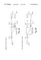
- FIGS. 1A and 1B and FIGS. 2A and 2BTwo examples of prior art optical polarization beam splitter/combiners are shown in FIGS. 1A and 1B and FIGS. 2A and 2B, respectively.
- an input beamenters from the fiber located at the left side of the figure.
- the incoming beam from fiber 1 at the leftis collimated by the lens 1 , and then enters the optical polarization beam splitter cube.
- the optical polarization beam splitter cubeis able to split an arbitrary polarized light into two separated beams with orthogonally polarized directions.
- a first beamexits to the right and is coupled to fiber 2 through lens 2 .
- a second beamexits in an upward direction and is coupled to fiber 3 through lens 3 .
- an optical polarization beam splitteris realized.
- These three fiberscould each be a single mode fiber, a polarization maintaining (PM) fiber, or even a multi-mode fiber.
- PMpolarization maintaining
- the prior-art device depicted in FIG. 1Amay be used as a bi-directional device if fiber 2 and fiber 3 are PM fibers, such that the optical beam polarization states coming from these two fibers are well defined and orthogonal to each other. Then these two beams can be added together at fiber 1 as shown in FIG. 1 B. In this way, an optical polarization beam combiner is realized.
- the device depicted in FIGS. 1A and 1Bfunctions for its intended purpose. It however, suffers from several disadvantages, such as a larger device size necessitated by the need to employ an orthogonally disposed beam, suffer from a low extinction ratio, difficult to manage the fibers.
- FIGS. 2A and 2BA second prior-art embodiment of an optical polarization beam combiner/splitter is depicted in FIGS. 2A and 2B.
- the optical principles of operation of the embodiment of FIGS. 2A and 2Bare almost the same as those of FIGS. 1A and 1B.
- a birefringent crystalis used to split the incoming arbitrary polarization light focussed from fiber 1 by lens 1 into two parallel beams having orthogonal polarization directions. These two beams are focused into fiber 2 and fiber 3 , respectively, by lenses 2 and 3 , such that the optical polarization beam splitter is realized.
- an optical polarization beam combinercan be realized as well. Compared to the embodiments of FIGS. 1A and 1B, the approach of FIGS. 2A and 2B provides high extinction ratio, employs fewer optical parts, and could be manufactured without the use of an optical epoxy in the optical path.
- the device depicted in FIGS. 2A and 2Bhas its own drawbacks. Since fiber 2 and fiber 3 are located at the same side of the device, the birefringent crystal must have a length sufficient separate the two beams enough to accommodate the required spacing between lenses 2 and 3 . Typically, lenses for this application have diameters of around 1.8 mm, requiring the minimum spacing between lens axes to also be about 1.8 mm. A birefringent must have a length of about 18 mm to provide the required beam separation of at least about 1.8 mm to accommodate the placement of lenses 2 and 3 .
- An optical polarization beam splittercomprises a first optical fiber having an end defining a first optical axis, a second optical fiber having an end defining a second optical axis, and a third optical fiber having an end defining a third optical axis parallel to and spaced apart from the second optical axis.
- a collimating lensis disposed along the first optical axis positioned to form a collimated optical beam from the first optical fiber.
- a focussing lensis disposed along a path of the collimated optical beam.
- a birefringent walk-off crystalhas a first face adjacent to the focussing lens and a second face located at a focal plane of the focussing lens and in contact with the ends of the second and third optical fibers.
- the birefringent crystalis oriented such that and has a thickness between its first and second faces selected such that a first component of the optical beam having a first polarization exits the crystal at its second face and enters the end of the second optical fiber along the second optical axis and a second component of the optical beam having a second polarization orthogonal to the polarization of the first polarization exits the crystal at its second face and enters the end of the third optical fiber along the third optical axis.
- An optical polarization beam splittercomprises a first optical fiber having an end defining a first optical axis, a second optical fiber having an end defining a second optical axis, and a third optical fiber having an end defining a third optical axis parallel to and spaced apart from the second optical axis.
- a collimating lensis disposed along the first optical axis and is positioned to form a collimated optical beam from the first optical fiber.
- a birefringent walk-off crystalis disposed in a path of the collimated optical beam.
- the crystalis oriented such that and has a thickness between first and second faces thereof selected such that a first component of the optical beam having a first polarization transits the crystal along a first path and a second component of the optical beam having a second polarization orthogonal to that of the first polarization transits the crystal along a second path disposed at a walkoff angle with respect to the first path.
- the first and second pathsexit the second face of the crystal as substantially parallel first and second paths.
- a Wollaston prism(a pair of wedges) is disposed along the substantially parallel first and second paths and oriented such as to bend the substantially parallel first and second paths towards each other to form converging first and second paths.
- a focussing lensis disposed along the converging first and second paths and positioned such that a first component optical beam travelling along the first converging path is directed into the end of the second optical fiber along the second optical axis and a second component optical beam travelling along the second converging path is directed into the end of the third optical fiber along the third optical axis.
- An optical polarization beam splittercomprises a first optical fiber having an end defining a first optical axis, a second optical fiber having an end defining a second optical axis, and a third optical fiber having an end defining a third optical axis parallel to and spaced apart from the second optical axis.
- a collimating lensis disposed along the first optical axis and is positioned to form a collimated optical beam from the first optical fiber.
- a first Wollaston prismis disposed in a path of the collimated optical beam and oriented such that a first component of the optical beam having a first polarization transits the prism along a first path disposed at a first angle with respect to the first optical axis and a second component of the optical beam having a second polarization orthogonal to that of the first polarization transits the prism along a second path disposed at a second angle with respect to the first optical axis, the first and second angles being substantially symmetrical about the first optical axis.
- a second Wollaston prismis disposed along the first and second paths and oriented such as to bend the first and second paths towards each other to form converging first and second paths.
- a focussing lensis disposed along the converging first and second paths and positioned such that a first component optical beam travelling along the first converging path is directed into the end of the second optical fiber along the second optical axis and a second component optical beam travelling along the second converging path is directed into the end of the third optical fiber along the third optical axis.
- An optical polarization beam splittercomprises a first optical fiber having an end defining a first optical axis, a second optical fiber having an end defining a second optical axis, and a third optical fiber having an end defining a third optical axis parallel to and spaced apart from the second optical axis.
- the second and third optical axesare symmetrical about the first optical axis.
- a first focussing lensis disposed along the first optical axis.
- a Wollaston prismis disposed at a location along the first optical axis where a focal point of the first focussing lens lies on an interface between two component pieces of the prism wedge such that a first component of an optical beam from the first optical fiber having a first polarization is directed along a first path disposed at a first angle with respect to the first optical axis and a second component of the optical beam having a second polarization orthogonal to that of sa the id first polarization is directed along a second path disposed at a second angle with respect to the first optical axis, the first and second angles being substantially symmetrical about the first optical axis.
- a second focussing lensis disposed along the first and second paths at a location selected to focus a first component optical beam into the end of the second optical fiber to focus a second component optical beam into the end of the third optical fiber.
- FIGS. 1A and 1Bare optical block diagrams of a first typical prior-art device useful as both a beam combiner and beam splitter.
- FIGS. 2A and 2Bare optical block diagrams of a second typical prior-art beam useful as both a beam combiner and beam splitter.
- FIG. 3is an optical block diagram of an optical polarization beam combiner/splitter in accordance with a first embodiment of the invention.
- FIG. 4is an optical block diagram of an optical polarization beam combiner/splitter in accordance with a second embodiment of the invention.
- FIG. 5is an optical block diagram of an optical polarization beam combiner/splitter in accordance with a third embodiment of the invention.
- FIG. 6is an optical block diagram of an optical polarization beam combiner/splitter in accordance with a fourth embodiment of the invention.
- a first fiber ferrule 12terminates fiber 14 at an angled face 16 thereof. Angled face 16 may be polished to an angle of about 8° to 10° as is the end of fiber 14 , as is known in the art to avoid deleterious effects from internal reflections in the optical fiber.
- Fiber 14carries a combined optical beam having a first component polarized in a first direction and a second optical beam polarized in a second direction orthogonal to the first direction.
- Fiber ferrule 12may have a length in the optical path direction of about 4 mm.
- a first lens 18may be spaced apart from fiber ferrule 12 by about 1 mm, may have a length in the optical path direction of about 3 mm and collimates the combined beam 20 emerging from the end of fiber 14 to produce a collimated combined beam 22 .
- a second lens 24may be spaced apart from first lens 18 by a distance of about 2 mm, may have a length in the optical path direction of about 3 mm and focuses the collimated combined beam 22 at a focal point 26 on a first face of birefringent walkoff crystal 28 .
- both lens 18 and lens 24may be graduated-index-of-refraction (GRIN) lenses, although conventional lenses may also be employed. Persons of ordinary skill in the art will appreciate that two separate lenses 18 and 24 are employed to perform the collimating and focussing functions to minimize the introduction of spherical aberrations.
- GRINgraduated-index-of-refraction
- Birefringent walkoff crystal 28is disposed at an angled face 30 of a ferrule 32 .
- a first component beam 34 from fiber 14passes through birefringent walk-off crystal 28 without refraction and a second component beam 36 passes through birefringent walk-off crystal 28 after being refracted at an downward angle.
- the thickness of birefringent walk-off crystal 28is selected so that the paths of beams 34 and 36 walk off from one another by a distance selected to match the spacing between optical fibers 38 and 40 held in ferrule 32 .
- Birefringent walk-off crystal 28may be comprised of a material such as YVO 4 , LiNbO 3 , etc.
- Typical thicknesses for birefringent walk-off crystal 28are in the range of from about 1 mm to about 2 mm and the distance between second lens 24 and ferrule 32 may be between about 1 mm to 2 mm. As those of ordinary skill in the art will appreciate, changing the incident angle of the birefringent walk-off crystal 28 will change the walk-off distance.
- optical polarizing beam combiner/splitter 10Because the optical paths in optical polarizing beam combiner/splitter 10 are all substantially parallel to a single optical axis, it can be packaged in a small, compact coaxial package, thus allowing for a smaller footprint and providing an improved ease in fiber management. Furthermore, the combination of optical components utilized in the embodiment of FIG. 3 permits close spacing of the two parallel-axis component beams and avoids the use of longer walk-off distances that would otherwise be required to provide sufficient beam spacing to accommodate the physical sizes of the optical components.
- the two parallel axis component beamsmay be spaced apart by as little as 0.125 mm (125 microns).
- the entire length of the splitter/combiner in the illustrative embodiment of FIG. 3is less than about 18 mm to about 20 mm.
- FIG. 3has been described by following the optical path from left to right across the figure and performs the function of a beam splitter.
- two oppositely polarized optical beams emerging from fibers 38 and 40 on the right and travelling in the direction from right to left across the drawing figurewill be combined and directed into fiber 14 at the left of FIG. 3 in accordance with the principles of the present invention, so long as optical fibers 38 and 40 are PM fibers.
- FIG. 4an optical block diagram of another embodiment of an optical polarized beam combiner/splitter 40 according to the present invention is shown.
- FIG. 4has been described for an orientation wherein a coincident beam having two components enters from optical fiber 42 at the left of the figure and is split into two component beams which emerge at the right side of the figure, but persons of ordinary skill in the art will appreciate that the analysis of two component beams entering the combiner/splitter from the right and being combined and directed into optical fiber 42 according to the present invention follows from the same optical principles described as responsible for beam splitting, so long as the optical fibers delivering the two component beams are polarization maintaining fibers.
- Optical fiber 42is disposed in ferrule 44 as is known in the art and is end polished at an angle as is known in the art. Diverging composite optical beam 46 from the end of optical fiber 42 is collimated by collimating lens 48 and collimated composite optical beam 50 enters birefringent walkoff crystal 52 . A first optical beam component transits crystal 52 on beam path 54 and a second optical beam component transits crystal 52 on beam path 56 at a walkoff angle with respect to beam path 54 . The length of birefringent crystal 52 is selected to provide a selected walkoff distance indicated by double-headed arrow 58 between the two component optical beams. In the illustrative embodiment of FIG.
- the ferrule 44may have a length of about 4 mm
- the collimating lens 48may be spaced from ferrule 44 by about 0.1 mm, and may have a length in the optical path direction of about 5 mm.
- the birefringent crystal 52may have a length of about 10 mm, and may be spaced from collimating lens 48 by about 0.2 mm.
- a Wollaston prism 60is disposed in the paths of optical beams 54 and 56 to bend the propagation directions of optical beams 54 and 56 so that they may be focussed by lens 62 such that they enter optical fibers 64 and 66 , respectively, disposed in ferrule 68 .
- lens 62comprises a GRIN lens, although a conventional lens may also be employed.
- the Wollaston prism 60may have a length of about 4 mm, and may be spaced from birefringent crystal 52 by about 0.2 mm.
- Lens 62may have a length of about 5 mm, and may be spaced from Wollaston prism 60 by about 0.2 mm.
- Ferrule 68may have a length of about 4 mm, and may be spaced from lens 62 by about 0.1 mm. The entire length of the splitter/combiner in the illustrative embodiment of FIG. 4 is less than about 30 mm to about 40 mm.
- FIG. 5an optical block diagram of another embodiment of an optical polarized beam combiner/splitter 70 according to the present invention is shown.
- FIG. 5has been described for an orientation wherein a coincident beam having two components enters from optical fiber 72 at the left of the figure and is split into two component beams which emerge at the right side of the figure, but persons of ordinary skill in the art will appreciate that the analysis of two component beams entering the combiner/splitter from the right and being combined and directed into optical fiber 72 according to the present invention follows from the same optical principles described as responsible for beam splitting, so long as the optical fibers delivering the two component beams are polarization maintaining fibers.
- Optical fiber 72is disposed in ferrule 74 as is known in the art and is end polished at an angle as is known in the art. Diverging composite optical beam 76 from the end of optical fiber 72 is collimated by collimating lens 78 .
- Ferrule 74may have a length of about 4 mm, and may be spaced from collimating lens 78 by about 0.1 mm.
- Collimated composite optical beam 80enters first Wollaston prism 82 .
- a first optical beam componenttransits prism 82 on beam path 84 and a second optical beam component transits crystal 82 on beam path 86 .
- Beam paths 84 and 86are substantially symmetrical about the optical axis of the first beam path 76 out of first fiber 72 .
- First Wollaston prism 82may have a length of about 2 mm, and may be spaced from collimating lens 78 by about 0.3 mm.
- a second Wollaston prism 88is disposed in the paths of optical beams 84 and 86 to bend the propagation directions of optical beams 84 and 86 towards each other so that they may be focussed by lens 90 such that they enter optical fibers 92 and 94 , respectively, disposed in ferrule 96 .
- lens 90comprises a GRIN lens, although a conventional lens may also be employed.
- Second Wollaston prism 88may have a length of about 2 mm, and may be spaced from first Wollaston prism 82 by about 4 mm.
- Lens 90may have a length of about 5 mm, and may be spaced from second Wollaston prism 88 by about 0.3 mm.
- Ferrule 96may have a length of about 4 mm, and may be spaced from lens 90 by about 0.1 mm.
- FIG. 6an optical block diagram of another embodiment of an optical polarized beam combiner/splitter 100 according to the present invention is shown.
- FIG. 6has been described for an orientation wherein a coincident beam having two components enters from optical fiber 102 at the left of the figure and is split into two component beams which emerge at the right side of the figure, but persons of ordinary skill in the art will appreciate that the analysis of two component beams entering the combiner/splitter from the right and being combined and directed into optical fiber 102 according to the present invention follows from the same optical principles described as responsible for beam splitting, so long as the optical fibers delivering the two component beams are polarization maintaining fibers.
- Optical fiber 102is disposed in ferrule 104 as is known in the art and is end polished at an angle as is known in the art. Diverging composite optical beam 106 from the end of optical fiber 102 is focussed by lens 108 into Wollaston prism 110 , disposed along the optical axis 112 of optical beam 106 .
- Ferrule 104may have a length of about 4 mm, and may be spaced from lens 108 by about 2 mm. Lens 108 may be spaced from Wollaston prism 110 by about 2 mm.
- Wollaston prism 110separates the composite optical beam 106 into component beams 114 and 116 , which leave the Wollaston prism 110 at two different angles symmetrical about optical axis 112 .
- Lens 118focuses component optical beams 114 and 116 such that they enter optical fibers 120 and 122 , respectively, disposed symmetrically about optical axis 112 in ferrule 124 .
- lenses 108 and 118comprise conventional lenses.
- Wollaston prism 110may have a length of about 4 mm, and may be spaced from lens 118 by about 2 mm.
- Lens 118may be spaced from ferrule 124 by about 2 mm.
- Ferrule 124may have a length of about 4 mm.
- the present inventionprovides advantages over prior art splitter/combiners.
- the embodiments of the present inventionemploy fewer optical parts compared to the prior art arrangements.
- the splitter/combiners of the present inventionprovide improved optical performance including benefits such as lower insertion loss and possibly higher optical polarization extinction ratio by using higher extinction ratio parts.
- the present inventionallows manufacture of splitter combiners having much smaller footprints than those of the prior art and permits use of compact coaxial packaging to permit easier fiber management. Because the optical path is epoxy free, higher optical power handling capability is enabled.
- modified Wollaston prismsfabricated with their optical axes aligned with the optical axes of the input and output fibers will be employed.
- the Wollaston prismwill have an optical axis disposed at an angle of 45°. This also applies to the walkoff crystals in the other embodiments.
- the disclosed embodiments of the optical polarized beam combiner/splitter according to the present inventionare more compact than those of the prior art.
- the optical path length of the embodiment of FIG. 3may be about 18 mm.
- the combined length of the elements in the optical path of the embodiment of FIG. 3is less than about 32 mm.
- the entire packaged optical polarized beam combiner/splitter according to FIG. 3 of the present inventioncan fit in a package approximately 20 mm long having a diameter of about 5.5 mm.
- the optical path length of the embodiment of FIG. 4may be about 33 mm.
- the combined length of the elements in the optical path of the embodiment of FIG. 4is less than about 32 mm.
- the entire packaged optical polarized beam combiner/splitter according to FIG. 4 of the present inventioncan fit in a package approximately 36 mm long having a diameter of about 5.5 mm.
- the optical path length of the embodiment of FIG. 5may be about 27 mm.
- the combined length of the elements in the optical path of the embodiment of FIG. 5is less than about 26 mm.
- the entire packaged optical polarized beam combiner/splitter according to FIG. 5 of the present inventioncan fit in a package approximately 4 mm by 30 mm having a diameter of about 5.5 mm.
- the optical path length of the embodiment of FIG. 6may be about 28 mm.
- the combined length of the elements in the optical path of the embodiment of FIG. 6is less than 20 mm.
- the entire packaged optical polarized beam combiner/splitter according to FIG. 6 of the present inventioncan fit in a package approximately 30 mm long having a diameter of about 5.5 mm.
Landscapes
- Physics & Mathematics (AREA)
- General Physics & Mathematics (AREA)
- Optics & Photonics (AREA)
- Optical Couplings Of Light Guides (AREA)
- Optical Elements Other Than Lenses (AREA)
Abstract
Description
Claims (13)
Priority Applications (6)
| Application Number | Priority Date | Filing Date | Title |
|---|---|---|---|
| US09/365,680US6282025B1 (en) | 1999-08-02 | 1999-08-02 | Optical polarization beam combiner/splitter |
| AU63613/00AAU6361300A (en) | 1999-08-02 | 2000-07-20 | Optical polarization beam combiner/splitter |
| PCT/US2000/019903WO2001009655A1 (en) | 1999-08-02 | 2000-07-20 | Optical polarization beam combiner/splitter |
| US09/702,279US6373631B1 (en) | 1999-08-02 | 2000-10-30 | Optical polarization beam combiner/splitter |
| US09/702,538US6331913B1 (en) | 1999-08-02 | 2000-10-30 | Optical polarization beam combiner/splitter |
| US09/702,280US6859316B1 (en) | 1999-08-02 | 2000-10-30 | Optical polarization beam combiner/splitter |
Applications Claiming Priority (1)
| Application Number | Priority Date | Filing Date | Title |
|---|---|---|---|
| US09/365,680US6282025B1 (en) | 1999-08-02 | 1999-08-02 | Optical polarization beam combiner/splitter |
Related Child Applications (3)
| Application Number | Title | Priority Date | Filing Date |
|---|---|---|---|
| US09/702,538DivisionUS6331913B1 (en) | 1999-08-02 | 2000-10-30 | Optical polarization beam combiner/splitter |
| US09/702,280DivisionUS6859316B1 (en) | 1999-08-02 | 2000-10-30 | Optical polarization beam combiner/splitter |
| US09/702,279DivisionUS6373631B1 (en) | 1999-08-02 | 2000-10-30 | Optical polarization beam combiner/splitter |
Publications (1)
| Publication Number | Publication Date |
|---|---|
| US6282025B1true US6282025B1 (en) | 2001-08-28 |
Family
ID=23439887
Family Applications (4)
| Application Number | Title | Priority Date | Filing Date |
|---|---|---|---|
| US09/365,680Expired - LifetimeUS6282025B1 (en) | 1999-08-02 | 1999-08-02 | Optical polarization beam combiner/splitter |
| US09/702,279Expired - LifetimeUS6373631B1 (en) | 1999-08-02 | 2000-10-30 | Optical polarization beam combiner/splitter |
| US09/702,538Expired - LifetimeUS6331913B1 (en) | 1999-08-02 | 2000-10-30 | Optical polarization beam combiner/splitter |
| US09/702,280Expired - Fee RelatedUS6859316B1 (en) | 1999-08-02 | 2000-10-30 | Optical polarization beam combiner/splitter |
Family Applications After (3)
| Application Number | Title | Priority Date | Filing Date |
|---|---|---|---|
| US09/702,279Expired - LifetimeUS6373631B1 (en) | 1999-08-02 | 2000-10-30 | Optical polarization beam combiner/splitter |
| US09/702,538Expired - LifetimeUS6331913B1 (en) | 1999-08-02 | 2000-10-30 | Optical polarization beam combiner/splitter |
| US09/702,280Expired - Fee RelatedUS6859316B1 (en) | 1999-08-02 | 2000-10-30 | Optical polarization beam combiner/splitter |
Country Status (3)
| Country | Link |
|---|---|
| US (4) | US6282025B1 (en) |
| AU (1) | AU6361300A (en) |
| WO (1) | WO2001009655A1 (en) |
Cited By (45)
| Publication number | Priority date | Publication date | Assignee | Title |
|---|---|---|---|---|
| US6331913B1 (en) | 1999-08-02 | 2001-12-18 | New Focus, Inc. | Optical polarization beam combiner/splitter |
| US6411749B2 (en)* | 2000-05-11 | 2002-06-25 | Micro-Optice, Inc. | In-line fiber optic polarization combiner/divider |
| US20020110307A1 (en)* | 2001-02-14 | 2002-08-15 | Yonglin Huang | Optical polarization beam splitter/combiner with isolation in the backward optical path |
| US20020118463A1 (en)* | 2000-11-03 | 2002-08-29 | Jds Uniphase Corporation | 3-port optical device |
| WO2002075377A1 (en)* | 2001-03-16 | 2002-09-26 | Corning Incorporated | Polarization combiner/splitter |
| US20020181824A1 (en)* | 2001-05-30 | 2002-12-05 | Shangyuan Huang | Compact polarization beam combiner/splitter |
| US6498875B1 (en)* | 2000-05-01 | 2002-12-24 | E20 Communications Inc. | Optical connector for connecting a plurality of light sources to a plurality of light sinks |
| US6529325B1 (en)* | 1999-09-16 | 2003-03-04 | Micro Optics, Inc. | Polarization based optical splitter/combiner |
| US20030063832A1 (en)* | 2001-09-28 | 2003-04-03 | Hellman Scott M. | Multiple polarization combiner-splitter-isolator and method of manufacturing the same |
| US6587267B2 (en)* | 2001-11-09 | 2003-07-01 | Jds Uniphase Inc. | Beam directing device |
| WO2003091769A1 (en)* | 2002-04-23 | 2003-11-06 | Corning Incorporated | Telescopic collimator and method of manufacture |
| US6704469B1 (en)* | 2000-09-12 | 2004-03-09 | Finisar Corporation | Polarization beam combiner/splitter |
| US20040070827A1 (en)* | 2002-10-15 | 2004-04-15 | Wei-Zhong Li | Reflective variable attenuator and tap monitor |
| US20040086214A1 (en)* | 2002-07-10 | 2004-05-06 | Finisar Corporation | Optical circulator for bi-directional communication |
| US6741764B2 (en)* | 2001-11-13 | 2004-05-25 | Adc Telecommunications, Inc. | Polarization beam separator and combiner |
| US6765935B2 (en)* | 2000-12-15 | 2004-07-20 | The Furukawa Electric Co., Ltd. | Semiconductor laser module, manufacturing method thereof and optical amplifier |
| US6782028B2 (en)* | 2000-12-15 | 2004-08-24 | The Furukawa Electric Co., Ltd. | Semiconductor laser device for use in a semiconductor laser module and an optical amplifier |
| US20040208601A1 (en)* | 2002-01-24 | 2004-10-21 | Ronson Tan | Systems, methods and apparatus for bi-directional optical transceivers |
| US20050018967A1 (en)* | 2002-07-10 | 2005-01-27 | Yonglin Huang | Plug-in module for providing bi-directional data transmission |
| US6873462B2 (en) | 2002-04-09 | 2005-03-29 | Oplink Communications, Inc. | Three-port circulator |
| US6900933B1 (en) | 2002-04-23 | 2005-05-31 | Oplink Communications, Inc. | Integrated two-pump combiner for optical fiber amplifiers |
| US6987896B1 (en) | 2002-04-09 | 2006-01-17 | Oplink Communications, Inc. | Optical isolator |
| US7006287B2 (en)* | 2004-02-06 | 2006-02-28 | Industrial Technology Research Institute | Optical polarization beam combiner |
| US7039278B1 (en) | 2002-07-10 | 2006-05-02 | Finisar Corporation | Single-fiber bi-directional transceiver |
| US7043101B1 (en) | 2002-07-13 | 2006-05-09 | Finisar Corporation | Integrated optical pump module |
| US7263250B1 (en) | 2002-10-18 | 2007-08-28 | Finisar Corporation | Optical switch using polarization beam splitters |
| US20070295090A1 (en)* | 2006-06-26 | 2007-12-27 | Michael Naumov | Device for determining acceleration |
| US20080055719A1 (en)* | 2006-08-31 | 2008-03-06 | Perkins Raymond T | Inorganic, Dielectric Grid Polarizer |
| US7630133B2 (en) | 2004-12-06 | 2009-12-08 | Moxtek, Inc. | Inorganic, dielectric, grid polarizer and non-zero order diffraction grating |
| US7789515B2 (en) | 2007-05-17 | 2010-09-07 | Moxtek, Inc. | Projection device with a folded optical path and wire-grid polarizer |
| US7800823B2 (en) | 2004-12-06 | 2010-09-21 | Moxtek, Inc. | Polarization device to polarize and further control light |
| US7813039B2 (en) | 2004-12-06 | 2010-10-12 | Moxtek, Inc. | Multilayer wire-grid polarizer with off-set wire-grid and dielectric grid |
| US7961393B2 (en) | 2004-12-06 | 2011-06-14 | Moxtek, Inc. | Selectively absorptive wire-grid polarizer |
| US8248696B2 (en) | 2009-06-25 | 2012-08-21 | Moxtek, Inc. | Nano fractal diffuser |
| WO2012100209A3 (en)* | 2011-01-21 | 2012-10-04 | Finisar Corporation | Multi-laser transmitter optical subassemblies for optoelectronic modules |
| US8611007B2 (en) | 2010-09-21 | 2013-12-17 | Moxtek, Inc. | Fine pitch wire grid polarizer |
| US8755113B2 (en) | 2006-08-31 | 2014-06-17 | Moxtek, Inc. | Durable, inorganic, absorptive, ultra-violet, grid polarizer |
| US8873144B2 (en) | 2011-05-17 | 2014-10-28 | Moxtek, Inc. | Wire grid polarizer with multiple functionality sections |
| US8913320B2 (en) | 2011-05-17 | 2014-12-16 | Moxtek, Inc. | Wire grid polarizer with bordered sections |
| US8913321B2 (en) | 2010-09-21 | 2014-12-16 | Moxtek, Inc. | Fine pitch grid polarizer |
| US8922890B2 (en) | 2012-03-21 | 2014-12-30 | Moxtek, Inc. | Polarizer edge rib modification |
| US20160025929A1 (en)* | 2014-06-26 | 2016-01-28 | Commscope, Inc. Of North Carolina | Optical tap |
| US9250355B2 (en) | 2011-04-06 | 2016-02-02 | Futurwei Technologies, Inc. | Device and method for optical beam combination |
| US9348076B2 (en) | 2013-10-24 | 2016-05-24 | Moxtek, Inc. | Polarizer with variable inter-wire distance |
| DE102006040858B4 (en)* | 2005-08-31 | 2018-01-11 | Zoller & Fröhlich GmbH | Transceiver and laser scanner |
Families Citing this family (16)
| Publication number | Priority date | Publication date | Assignee | Title |
|---|---|---|---|---|
| US6813414B1 (en)* | 2000-07-17 | 2004-11-02 | Finisar Corporation | Fiber optical pigtail geometry for improved extinction ratio of polarization maintaining fibers |
| US6434284B1 (en)* | 2000-12-07 | 2002-08-13 | Corning Incorporated | Beam converter for enhancing brightness of polarized light sources |
| US20020105984A1 (en)* | 2000-12-15 | 2002-08-08 | The Furukawa Electric Co., Ltd. | Integrated laser beam synthesizing module for use in a semiconductor laser module and an optical amplifier |
| JP2002252420A (en)* | 2000-12-15 | 2002-09-06 | Furukawa Electric Co Ltd:The | Semiconductor laser device, semiconductor laser module, method of manufacturing the same, and optical fiber amplifier |
| US6816260B2 (en) | 2001-05-17 | 2004-11-09 | Thorlabs Gmbh | Fiber polarimeter, the use thereof, as well as polarimetric method |
| US7495765B2 (en) | 2001-05-17 | 2009-02-24 | Thorlabs Gmbh | Fiber polarimeter, the use thereof, as well as polarimetric method |
| US7116479B1 (en) | 2001-07-19 | 2006-10-03 | Wavesplitter Technologies, Inc. | Array polarization beamsplitter and combiner |
| CN1324335C (en)* | 2001-08-28 | 2007-07-04 | 菲尼萨公司 | Method and apparatus for precision tuning an optical filter using a ball-end joint |
| US6876784B2 (en)* | 2002-05-30 | 2005-04-05 | Nanoopto Corporation | Optical polarization beam combiner/splitter |
| US6823093B2 (en)* | 2002-06-11 | 2004-11-23 | Jds Uniphase Corporation | Tunable micro-optic architecture for combining light beam outputs of dual capillary polarization-maintaining optical fibers |
| TWI220698B (en) | 2002-10-25 | 2004-09-01 | Ind Tech Res Inst | Three port optical polarization beam combiner |
| US7373028B2 (en)* | 2002-10-30 | 2008-05-13 | Finisar Corporation | Polarization maintaining coupler |
| US20100158521A1 (en)* | 2008-12-18 | 2010-06-24 | Alcatel-Lucent Usa Inc. | Optical mixer for coherent detection of polarization-multiplexed signals |
| MY167202A (en) | 2009-03-20 | 2018-08-13 | Alcatel Lucent | Coherent optical detector having a multifunctional waveguide grating |
| DE102009044910B4 (en) | 2009-06-23 | 2024-09-05 | Seereal Technologies S.A. | Spatial light modulation device for modulating a wave field with complex information |
| US10698163B2 (en) | 2018-10-30 | 2020-06-30 | Hewlett Packard Enterprise Development Lp | Polarization diversity optical interface assembly |
Citations (6)
| Publication number | Priority date | Publication date | Assignee | Title |
|---|---|---|---|---|
| US4570064A (en)* | 1982-07-21 | 1986-02-11 | Hitachi, Ltd. | Optical D.C. electric-field measuring apparatus with optic sensing means exhibiting both electrooptic and photoelectric effects |
| US4671613A (en) | 1985-11-12 | 1987-06-09 | Gte Laboratories Inc. | Optical beam splitter prism |
| WO1990015357A1 (en)* | 1989-05-30 | 1990-12-13 | Raymond Hesline | Birefringent polarizing device |
| US5291571A (en) | 1992-03-19 | 1994-03-01 | Fujitsu Limited | Duplicated light source module |
| EP0863425A2 (en) | 1997-02-24 | 1998-09-09 | Jds Fitel Inc. | Optical device for splitting an input beam into two orthogonal polarization states |
| EP0959375A2 (en) | 1998-05-21 | 1999-11-24 | Jds Fitel Inc. | Optical attenuator |
Family Cites Families (6)
| Publication number | Priority date | Publication date | Assignee | Title |
|---|---|---|---|---|
| JPH04335304A (en)* | 1991-05-10 | 1992-11-24 | Namiki Precision Jewel Co Ltd | Polarized light coupler with microlens optical fiber terminal |
| JP2775547B2 (en)* | 1992-02-17 | 1998-07-16 | 秩父小野田株式会社 | Optical isolator |
| US6014256A (en) | 1997-07-18 | 2000-01-11 | Cheng; Yihao | Polarizing beam splitter/combiner |
| US5930039A (en) | 1997-12-08 | 1999-07-27 | U.S.A Kaifa Technology, Inc. | Optical circulator |
| US6049426A (en)* | 1998-08-17 | 2000-04-11 | New Focus, Inc. | Compact polarization insensitive circulators with simplified structure and low polarization mode dispersion |
| US6282025B1 (en) | 1999-08-02 | 2001-08-28 | New Focus, Inc. | Optical polarization beam combiner/splitter |
- 1999
- 1999-08-02USUS09/365,680patent/US6282025B1/ennot_activeExpired - Lifetime
- 2000
- 2000-07-20AUAU63613/00Apatent/AU6361300A/ennot_activeAbandoned
- 2000-07-20WOPCT/US2000/019903patent/WO2001009655A1/enactiveApplication Filing
- 2000-10-30USUS09/702,279patent/US6373631B1/ennot_activeExpired - Lifetime
- 2000-10-30USUS09/702,538patent/US6331913B1/ennot_activeExpired - Lifetime
- 2000-10-30USUS09/702,280patent/US6859316B1/ennot_activeExpired - Fee Related
Patent Citations (6)
| Publication number | Priority date | Publication date | Assignee | Title |
|---|---|---|---|---|
| US4570064A (en)* | 1982-07-21 | 1986-02-11 | Hitachi, Ltd. | Optical D.C. electric-field measuring apparatus with optic sensing means exhibiting both electrooptic and photoelectric effects |
| US4671613A (en) | 1985-11-12 | 1987-06-09 | Gte Laboratories Inc. | Optical beam splitter prism |
| WO1990015357A1 (en)* | 1989-05-30 | 1990-12-13 | Raymond Hesline | Birefringent polarizing device |
| US5291571A (en) | 1992-03-19 | 1994-03-01 | Fujitsu Limited | Duplicated light source module |
| EP0863425A2 (en) | 1997-02-24 | 1998-09-09 | Jds Fitel Inc. | Optical device for splitting an input beam into two orthogonal polarization states |
| EP0959375A2 (en) | 1998-05-21 | 1999-11-24 | Jds Fitel Inc. | Optical attenuator |
Cited By (63)
| Publication number | Priority date | Publication date | Assignee | Title |
|---|---|---|---|---|
| US6373631B1 (en) | 1999-08-02 | 2002-04-16 | New Focus Inc. | Optical polarization beam combiner/splitter |
| US6331913B1 (en) | 1999-08-02 | 2001-12-18 | New Focus, Inc. | Optical polarization beam combiner/splitter |
| US6529325B1 (en)* | 1999-09-16 | 2003-03-04 | Micro Optics, Inc. | Polarization based optical splitter/combiner |
| US6498875B1 (en)* | 2000-05-01 | 2002-12-24 | E20 Communications Inc. | Optical connector for connecting a plurality of light sources to a plurality of light sinks |
| US6411749B2 (en)* | 2000-05-11 | 2002-06-25 | Micro-Optice, Inc. | In-line fiber optic polarization combiner/divider |
| US6704469B1 (en)* | 2000-09-12 | 2004-03-09 | Finisar Corporation | Polarization beam combiner/splitter |
| US20020118463A1 (en)* | 2000-11-03 | 2002-08-29 | Jds Uniphase Corporation | 3-port optical device |
| US6782028B2 (en)* | 2000-12-15 | 2004-08-24 | The Furukawa Electric Co., Ltd. | Semiconductor laser device for use in a semiconductor laser module and an optical amplifier |
| US6765935B2 (en)* | 2000-12-15 | 2004-07-20 | The Furukawa Electric Co., Ltd. | Semiconductor laser module, manufacturing method thereof and optical amplifier |
| US20020110307A1 (en)* | 2001-02-14 | 2002-08-15 | Yonglin Huang | Optical polarization beam splitter/combiner with isolation in the backward optical path |
| WO2002075377A1 (en)* | 2001-03-16 | 2002-09-26 | Corning Incorporated | Polarization combiner/splitter |
| US20020176644A1 (en)* | 2001-03-16 | 2002-11-28 | Bhagavatula Venkata A. | Polarization combiner/splitter |
| US20020181824A1 (en)* | 2001-05-30 | 2002-12-05 | Shangyuan Huang | Compact polarization beam combiner/splitter |
| US6782146B2 (en)* | 2001-09-28 | 2004-08-24 | Corning Incorporated | Multiple polarization combiner-splitter-isolator and method of manufacturing the same |
| US20030063832A1 (en)* | 2001-09-28 | 2003-04-03 | Hellman Scott M. | Multiple polarization combiner-splitter-isolator and method of manufacturing the same |
| US6587267B2 (en)* | 2001-11-09 | 2003-07-01 | Jds Uniphase Inc. | Beam directing device |
| US20070189657A1 (en)* | 2001-11-13 | 2007-08-16 | Adc Telecommunications, Inc. | Polarization beam separator and combiner |
| US6741764B2 (en)* | 2001-11-13 | 2004-05-25 | Adc Telecommunications, Inc. | Polarization beam separator and combiner |
| US7359584B2 (en) | 2001-11-13 | 2008-04-15 | Adc Telecommunications, Inc. | Polarization beam separator and combiner |
| US20040213512A1 (en)* | 2001-11-13 | 2004-10-28 | Wu Pingfan P. | Polarization beam separator and combiner |
| US7206479B2 (en) | 2001-11-13 | 2007-04-17 | Adc Telecommunications, Inc. | Polarization beam separator and combiner |
| US20040208601A1 (en)* | 2002-01-24 | 2004-10-21 | Ronson Tan | Systems, methods and apparatus for bi-directional optical transceivers |
| US6954592B2 (en) | 2002-01-24 | 2005-10-11 | Jds Uniphase Corporation | Systems, methods and apparatus for bi-directional optical transceivers |
| US6987896B1 (en) | 2002-04-09 | 2006-01-17 | Oplink Communications, Inc. | Optical isolator |
| US6873462B2 (en) | 2002-04-09 | 2005-03-29 | Oplink Communications, Inc. | Three-port circulator |
| US20040001677A1 (en)* | 2002-04-23 | 2004-01-01 | Kondis John P. | Telescopic collimator and method of manufacture |
| WO2003091769A1 (en)* | 2002-04-23 | 2003-11-06 | Corning Incorporated | Telescopic collimator and method of manufacture |
| US6900933B1 (en) | 2002-04-23 | 2005-05-31 | Oplink Communications, Inc. | Integrated two-pump combiner for optical fiber amplifiers |
| US7039278B1 (en) | 2002-07-10 | 2006-05-02 | Finisar Corporation | Single-fiber bi-directional transceiver |
| US7031574B2 (en) | 2002-07-10 | 2006-04-18 | Finisar Corporation | Plug-in module for providing bi-directional data transmission |
| US20050018967A1 (en)* | 2002-07-10 | 2005-01-27 | Yonglin Huang | Plug-in module for providing bi-directional data transmission |
| US20040086214A1 (en)* | 2002-07-10 | 2004-05-06 | Finisar Corporation | Optical circulator for bi-directional communication |
| US7043101B1 (en) | 2002-07-13 | 2006-05-09 | Finisar Corporation | Integrated optical pump module |
| US20040070827A1 (en)* | 2002-10-15 | 2004-04-15 | Wei-Zhong Li | Reflective variable attenuator and tap monitor |
| US6839170B2 (en) | 2002-10-15 | 2005-01-04 | Oplink Communications, Inc. | Optical isolator |
| US7263250B1 (en) | 2002-10-18 | 2007-08-28 | Finisar Corporation | Optical switch using polarization beam splitters |
| US7006287B2 (en)* | 2004-02-06 | 2006-02-28 | Industrial Technology Research Institute | Optical polarization beam combiner |
| US7800823B2 (en) | 2004-12-06 | 2010-09-21 | Moxtek, Inc. | Polarization device to polarize and further control light |
| US7630133B2 (en) | 2004-12-06 | 2009-12-08 | Moxtek, Inc. | Inorganic, dielectric, grid polarizer and non-zero order diffraction grating |
| US7813039B2 (en) | 2004-12-06 | 2010-10-12 | Moxtek, Inc. | Multilayer wire-grid polarizer with off-set wire-grid and dielectric grid |
| US7961393B2 (en) | 2004-12-06 | 2011-06-14 | Moxtek, Inc. | Selectively absorptive wire-grid polarizer |
| US8027087B2 (en) | 2004-12-06 | 2011-09-27 | Moxtek, Inc. | Multilayer wire-grid polarizer with off-set wire-grid and dielectric grid |
| DE102006040858B8 (en) | 2005-08-31 | 2018-03-08 | Zoller & Fröhlich GmbH | Transceiver and laser scanner |
| DE102006040858B4 (en)* | 2005-08-31 | 2018-01-11 | Zoller & Fröhlich GmbH | Transceiver and laser scanner |
| US20070295090A1 (en)* | 2006-06-26 | 2007-12-27 | Michael Naumov | Device for determining acceleration |
| US20080055719A1 (en)* | 2006-08-31 | 2008-03-06 | Perkins Raymond T | Inorganic, Dielectric Grid Polarizer |
| US8755113B2 (en) | 2006-08-31 | 2014-06-17 | Moxtek, Inc. | Durable, inorganic, absorptive, ultra-violet, grid polarizer |
| US7789515B2 (en) | 2007-05-17 | 2010-09-07 | Moxtek, Inc. | Projection device with a folded optical path and wire-grid polarizer |
| US8248696B2 (en) | 2009-06-25 | 2012-08-21 | Moxtek, Inc. | Nano fractal diffuser |
| US8611007B2 (en) | 2010-09-21 | 2013-12-17 | Moxtek, Inc. | Fine pitch wire grid polarizer |
| US8913321B2 (en) | 2010-09-21 | 2014-12-16 | Moxtek, Inc. | Fine pitch grid polarizer |
| US8625989B2 (en) | 2011-01-21 | 2014-01-07 | Finisar Corporation | Multi-laser transmitter optical subassemblies for optoelectronic modules |
| WO2012100209A3 (en)* | 2011-01-21 | 2012-10-04 | Finisar Corporation | Multi-laser transmitter optical subassemblies for optoelectronic modules |
| US9250355B2 (en) | 2011-04-06 | 2016-02-02 | Futurwei Technologies, Inc. | Device and method for optical beam combination |
| US9759867B2 (en) | 2011-04-06 | 2017-09-12 | Futurewei Technologies, Inc. | Device and method for optical beam combination |
| US8913320B2 (en) | 2011-05-17 | 2014-12-16 | Moxtek, Inc. | Wire grid polarizer with bordered sections |
| US8873144B2 (en) | 2011-05-17 | 2014-10-28 | Moxtek, Inc. | Wire grid polarizer with multiple functionality sections |
| US8922890B2 (en) | 2012-03-21 | 2014-12-30 | Moxtek, Inc. | Polarizer edge rib modification |
| US9348076B2 (en) | 2013-10-24 | 2016-05-24 | Moxtek, Inc. | Polarizer with variable inter-wire distance |
| US9354374B2 (en) | 2013-10-24 | 2016-05-31 | Moxtek, Inc. | Polarizer with wire pair over rib |
| US9632223B2 (en) | 2013-10-24 | 2017-04-25 | Moxtek, Inc. | Wire grid polarizer with side region |
| US20160025929A1 (en)* | 2014-06-26 | 2016-01-28 | Commscope, Inc. Of North Carolina | Optical tap |
| US9696495B2 (en)* | 2014-06-26 | 2017-07-04 | Commscope, Inc. Of North Carolina | Optical tap |
Also Published As
| Publication number | Publication date |
|---|---|
| WO2001009655A1 (en) | 2001-02-08 |
| US6859316B1 (en) | 2005-02-22 |
| US6373631B1 (en) | 2002-04-16 |
| AU6361300A (en) | 2001-02-19 |
| US6331913B1 (en) | 2001-12-18 |
Similar Documents
| Publication | Publication Date | Title |
|---|---|---|
| US6282025B1 (en) | Optical polarization beam combiner/splitter | |
| US5408354A (en) | Optical Isolator | |
| US6411749B2 (en) | In-line fiber optic polarization combiner/divider | |
| EP1176451A2 (en) | Isolated polarization beam splitter and combiner | |
| US7081996B2 (en) | Isolated polarization beam splitter and combiner | |
| US6532321B1 (en) | Fiber optic isolator for use with multiple-wavelength optical signals | |
| CN103913857B (en) | Optical isolation method and optical isolation device | |
| US7050234B2 (en) | Lossless beam combination in a dual fiber collimator using a polarizing beamsplitter | |
| US20020181824A1 (en) | Compact polarization beam combiner/splitter | |
| US6711311B2 (en) | Polarization beam splitter or combiner | |
| JP2002528764A (en) | Multi-port optical fiber isolator | |
| US20040184148A1 (en) | Integrated micro-optic architecture for combining and depolarizing plural polarized laser beams | |
| US20020118463A1 (en) | 3-port optical device | |
| US7173762B2 (en) | Optical isolator with reduced insertion loss and minimized polarization mode dispersion | |
| JPH1062720A (en) | Optical coupling module | |
| US5872878A (en) | Partial optical circulators | |
| US6813397B2 (en) | Micro-optic polarization beam multiplexing/de-multiplexing system | |
| EP1360530B1 (en) | Optical polarization beam splitter/combiner with isolation in the backward optical path | |
| US6529325B1 (en) | Polarization based optical splitter/combiner | |
| CA2353732A1 (en) | Optical multiplexing/demultiplexing module | |
| US6493140B1 (en) | Polarization splitter and combiner and optical devices using the same | |
| WO2004104664A1 (en) | Polarization device | |
| JP2003523538A (en) | Optical fiber device operating at two or more wavelengths | |
| WO2000048029A1 (en) | Compact multiple port optical isolator | |
| JPS6240423A (en) | Laser module provided with light isolator |
Legal Events
| Date | Code | Title | Description |
|---|---|---|---|
| AS | Assignment | Owner name:NEW FOCUS, INC., CALIFORNIA Free format text:ASSIGNMENT OF ASSIGNORS INTEREST;ASSIGNORS:HUANG, YONGLIN;XIE, PING;REEL/FRAME:010266/0228 Effective date:19990802 | |
| STCF | Information on status: patent grant | Free format text:PATENTED CASE | |
| AS | Assignment | Owner name:FINISAR CORPORATION, CALIFORNIA Free format text:ASSIGNMENT OF ASSIGNORS INTEREST;ASSIGNOR:NEW FOCUS, INC., A DELAWARE CORPORATION;REEL/FRAME:012745/0781 Effective date:20020510 Owner name:FINISAR CORPORATION, CALIFORNIA Free format text:ASSIGNMENT OF ASSIGNORS INTEREST;ASSIGNOR:NEW FOCUS, INC.;REEL/FRAME:012754/0661 Effective date:20020510 | |
| AS | Assignment | Owner name:FINISAR CORPORATION, CALIFORNIA Free format text:ASSIGNMENT OF ASSIGNORS INTEREST;ASSIGNOR:NEW FOCUS, INC.;REEL/FRAME:013056/0335 Effective date:20020510 | |
| FEPP | Fee payment procedure | Free format text:PAYOR NUMBER ASSIGNED (ORIGINAL EVENT CODE: ASPN); ENTITY STATUS OF PATENT OWNER: LARGE ENTITY | |
| FPAY | Fee payment | Year of fee payment:4 | |
| FPAY | Fee payment | Year of fee payment:8 | |
| FPAY | Fee payment | Year of fee payment:12 | |
| AS | Assignment | Owner name:BANK OF AMERICA, N.A., AS ADMINISTRATIVE AGENT, NO Free format text:NOTICE OF GRANT OF SECURITY INTEREST IN PATENTS;ASSIGNORS:II-VI INCORPORATED;MARLOW INDUSTRIES, INC.;EPIWORKS, INC.;AND OTHERS;REEL/FRAME:050484/0204 Effective date:20190924 Owner name:BANK OF AMERICA, N.A., AS ADMINISTRATIVE AGENT, NORTH CAROLINA Free format text:NOTICE OF GRANT OF SECURITY INTEREST IN PATENTS;ASSIGNORS:II-VI INCORPORATED;MARLOW INDUSTRIES, INC.;EPIWORKS, INC.;AND OTHERS;REEL/FRAME:050484/0204 Effective date:20190924 | |
| AS | Assignment | Owner name:II-VI DELAWARE, INC., DELAWARE Free format text:ASSIGNMENT OF ASSIGNORS INTEREST;ASSIGNOR:FINISAR CORPORATION;REEL/FRAME:052286/0001 Effective date:20190924 | |
| AS | Assignment | Owner name:PHOTOP TECHNOLOGIES, INC., CALIFORNIA Free format text:PATENT RELEASE AND REASSIGNMENT;ASSIGNOR:BANK OF AMERICA, N.A., AS ADMINISTRATIVE AGENT;REEL/FRAME:060574/0001 Effective date:20220701 Owner name:II-VI OPTOELECTRONIC DEVICES, INC., NEW JERSEY Free format text:PATENT RELEASE AND REASSIGNMENT;ASSIGNOR:BANK OF AMERICA, N.A., AS ADMINISTRATIVE AGENT;REEL/FRAME:060574/0001 Effective date:20220701 Owner name:II-VI DELAWARE, INC., PENNSYLVANIA Free format text:PATENT RELEASE AND REASSIGNMENT;ASSIGNOR:BANK OF AMERICA, N.A., AS ADMINISTRATIVE AGENT;REEL/FRAME:060574/0001 Effective date:20220701 Owner name:II-VI PHOTONICS (US), INC., MASSACHUSETTS Free format text:PATENT RELEASE AND REASSIGNMENT;ASSIGNOR:BANK OF AMERICA, N.A., AS ADMINISTRATIVE AGENT;REEL/FRAME:060574/0001 Effective date:20220701 Owner name:M CUBED TECHNOLOGIES, INC., CONNECTICUT Free format text:PATENT RELEASE AND REASSIGNMENT;ASSIGNOR:BANK OF AMERICA, N.A., AS ADMINISTRATIVE AGENT;REEL/FRAME:060574/0001 Effective date:20220701 Owner name:II-VI OPTICAL SYSTEMS, INC., CALIFORNIA Free format text:PATENT RELEASE AND REASSIGNMENT;ASSIGNOR:BANK OF AMERICA, N.A., AS ADMINISTRATIVE AGENT;REEL/FRAME:060574/0001 Effective date:20220701 Owner name:FINISAR CORPORATION, CALIFORNIA Free format text:PATENT RELEASE AND REASSIGNMENT;ASSIGNOR:BANK OF AMERICA, N.A., AS ADMINISTRATIVE AGENT;REEL/FRAME:060574/0001 Effective date:20220701 Owner name:OPTIUM CORPORATION, CALIFORNIA Free format text:PATENT RELEASE AND REASSIGNMENT;ASSIGNOR:BANK OF AMERICA, N.A., AS ADMINISTRATIVE AGENT;REEL/FRAME:060574/0001 Effective date:20220701 Owner name:COADNA PHOTONICS, INC., PENNSYLVANIA Free format text:PATENT RELEASE AND REASSIGNMENT;ASSIGNOR:BANK OF AMERICA, N.A., AS ADMINISTRATIVE AGENT;REEL/FRAME:060574/0001 Effective date:20220701 Owner name:KAILIGHT PHOTONICS, INC., CALIFORNIA Free format text:PATENT RELEASE AND REASSIGNMENT;ASSIGNOR:BANK OF AMERICA, N.A., AS ADMINISTRATIVE AGENT;REEL/FRAME:060574/0001 Effective date:20220701 Owner name:LIGHTSMYTH TECHNOLOGIES, INC., OREGON Free format text:PATENT RELEASE AND REASSIGNMENT;ASSIGNOR:BANK OF AMERICA, N.A., AS ADMINISTRATIVE AGENT;REEL/FRAME:060574/0001 Effective date:20220701 Owner name:EPIWORKS, INC., ILLINOIS Free format text:PATENT RELEASE AND REASSIGNMENT;ASSIGNOR:BANK OF AMERICA, N.A., AS ADMINISTRATIVE AGENT;REEL/FRAME:060574/0001 Effective date:20220701 Owner name:MARLOW INDUSTRIES, INC., TEXAS Free format text:PATENT RELEASE AND REASSIGNMENT;ASSIGNOR:BANK OF AMERICA, N.A., AS ADMINISTRATIVE AGENT;REEL/FRAME:060574/0001 Effective date:20220701 Owner name:II-VI INCORPORATED, PENNSYLVANIA Free format text:PATENT RELEASE AND REASSIGNMENT;ASSIGNOR:BANK OF AMERICA, N.A., AS ADMINISTRATIVE AGENT;REEL/FRAME:060574/0001 Effective date:20220701 |