US6281878B1 - Apparatus and method for inputing data - Google Patents
Apparatus and method for inputing dataDownload PDFInfo
- Publication number
- US6281878B1 US6281878B1US09/013,620US1362098AUS6281878B1US 6281878 B1US6281878 B1US 6281878B1US 1362098 AUS1362098 AUS 1362098AUS 6281878 B1US6281878 B1US 6281878B1
- Authority
- US
- United States
- Prior art keywords
- light
- input
- reference plane
- respect
- sensor
- Prior art date
- Legal status (The legal status is an assumption and is not a legal conclusion. Google has not performed a legal analysis and makes no representation as to the accuracy of the status listed.)
- Expired - Fee Related
Links
Images


Classifications
- G—PHYSICS
- G06—COMPUTING OR CALCULATING; COUNTING
- G06F—ELECTRIC DIGITAL DATA PROCESSING
- G06F3/00—Input arrangements for transferring data to be processed into a form capable of being handled by the computer; Output arrangements for transferring data from processing unit to output unit, e.g. interface arrangements
- G06F3/01—Input arrangements or combined input and output arrangements for interaction between user and computer
- G06F3/03—Arrangements for converting the position or the displacement of a member into a coded form
- G06F3/041—Digitisers, e.g. for touch screens or touch pads, characterised by the transducing means
- G06F3/042—Digitisers, e.g. for touch screens or touch pads, characterised by the transducing means by opto-electronic means
- G06F3/0428—Digitisers, e.g. for touch screens or touch pads, characterised by the transducing means by opto-electronic means by sensing at the edges of the touch surface the interruption of optical paths, e.g. an illumination plane, parallel to the touch surface which may be virtual
Definitions
- Input devicesare used in almost every aspect of everyday life, including computer keyboards and mice, automatic teller machines, vehicle controls, and countless other applications. Input devices, like most things, typically have a number of moving parts.
- a conventional keyboardfor example, has moveable keys that open and close electrical contacts. Moving parts, unfortunately, are likely to break or malfunction before other components, particularly solid state devices. Such malfunction or breakage is even more likely to occur in conditions that are dirty or dusty.
- input deviceshave become a limiting factor in the size of small electronic devices, such as laptop computers and personal organizers. For example, to be efficient a keyboard input device must have keys that are spaced at least as far apart as the size of the user's finger tips. Such a large keyboard has become a limiting factor as electronic devices become smaller.
- touch screenscan sense a user touching an image on the monitor.
- Such devicestypically require sensors and other devices in, on, or around the monitor.
- reducing the size of such an input deviceis limited to the size of the monitor.
- the needexists for an input device that is large enough to be used efficiently, and which can be contained within a small package, such as an electronic device, like as a laptop computer or a personal organizer.
- the needalso exists for an input device that is not susceptible to failure caused by particulate matter, such as dirt and dust.
- the present inventionalso includes a method of determining an input.
- the methodincludes providing a source of light, sensing light at an acute angle with respect to a reference plane, generating at least one signal indicative of sensed light, determining a position of an object with respect to the reference plane from the at least one signal indicative of the sensed light, and determining an input from the position of the object with respect to the reference plane.
- the present inventionovercomes deficiencies in the prior art by providing for an input device that is compact and that allows for a full sized keyboard or other input means to be provided. Unlike prior art devices that require sensors to be located directly above the area to be sensed or at the boundaries of the area to be sensed, the present invention allows the input device to be self contained and remote from the area to be sensed.
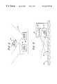
- FIG. 1is a block diagram illustrating an input device constructed in accordance with the present invention
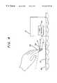
- FIG. 2is a top plan schematic view of the input device illustrating the orientation of the first and second sensors
- FIG. 3is a schematic representation of a projector and a light source oriented in an input device constructed in accordance with the present invention
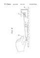
- FIG. 4is a perspective view of an input device sensing a user's finger
- FIG. 9is a combination side plan view and block diagram illustrating another embodiment of the present invention wherein the light source produces a plane of light adjacent to the input template;
- FIG. 10is a graphical representation of a two dimensional matrix type sensor illustrating how an image from a singe two dimensional matrix type sensor may be used to determine position of an object adjacent to an input template
- FIGS. 11 and 12illustrate one dimensional array type sensors that may be used in place of the two dimensional matrix type sensor illustrated in FIG. 10;
- FIG. 13is a block diagram illustrating an alternative embodiment of the present invention including projection glasses, such as may be used in virtual reality applications, to provide the user with an image of an input template;
- FIG. 14illustrates an alternative embodiment wherein an index light source provides an index mark for aligning an input template
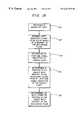
- FIG. 15is a block diagram illustrating a method of detecting an input with respect to a reference plane.
- FIG. 16is a block diagram illustrating a method of calibrating the input device.
- FIG. 1is a block diagram illustrating an input device 10 constructed in accordance with the present invention.
- the input device 10includes an input template 12 , a light source 14 , a first light sensor 16 , a second light sensor 18 , and a circuit 20 .
- the input template 12facilitates using the input device 10 and may be an image of an input device, such as a keyboard or a pointer.
- the input template 12may be a physical template, such as a surface with an image of an input device printed thereon.
- the input template 12may be a piece of paper or a piece of plastic with an image of a keyboard printed thereon.
- the input template 12may also be formed from light projected onto a solid surface.
- a projector 22may project an image of the input template 12 onto a solid surface, such as a desktop.
- the projector 22may be, for example, a slide projector or a laser projector.
- the projector 22may also provide several different input templates 12 , either simultaneously or individually. For example, a keyboard and pointer may initially be provided simultaneously.
- the input template 12may take other forms, such as a button panel, a keypad, and a CAD template.
- the projector 22may provide custom input templates 12 .
- the input template 12may also be formed from other than a projector 22 , such as being formed from a holographic image or from a spherical reflection. The input template 12 may even be eliminated, as described hereinbelow.
- the input template 12is located in a reference plane 24 .
- the reference plane 24is defined by the input device 10 and is used as a reference for determining input from a user. For example, if the input device 12 is acting as a keyboard, the reference 24 plane may be thought of as an imaginary keyboard. The user's motions are monitored with reference to the reference plane 24 to determine what keys on the keyboard are being selected. The reference plane 24 may be thought of as being further defined into keys on the keyboard, with each key having a position on the reference plane 24 so that motions from the user can be translated into characters selected from the keyboard.
- the light source 14provides light adjacent to the input template 12 .
- the light source 14may provide any of many types of light, including visible light, coherent light, ultraviolet light, and infrared light.
- the light source 14may be an incandescent lamp, a fluorescent lamp, or a laser.
- the light source 14need not be a mechanical part of the input device 10 , because the input device 10 may utilize ambient light from the surroundings or infrared light produced by a person's body. When the input device 10 is used on a top of a flat surface, the light source 14 will typically provide light above the input template 12 .
- the input device 10however, has many applications and it need not be used on top of a flat surface.
- the input device 10may be mounted vertically on a wall, such as an automatic teller machine, a control panel, or some other input device.
- the light source 14will provide light adjacent to the input template 12 , and from the perspective of a user, the light source 14 provides light in front of the input template 12 .
- the input device 10is mounted above the user, such as in the roof of an automobile or an airplane, the light source 14 will provide light adjacent to and below the input template 12 . In each of those embodiments, however, the light is provided adjacent to the input template 12 .
- the first and second light sensors 16 , 18are positioned to sense light at an acute angle with respect to the input template 12 , and to generate signals indicative of the sensed light.
- the first and second light sensors 16 , 18may be any of many types of light sensors.
- the first and second light sensors 16 , 18may be two dimensional matrix type light sensors and may also be one dimensional array type light sensors.
- the first and second light sensors 16 , 18may sense any of many types of light, such as visible light, coherent light, ultraviolet light, and infrared light.
- the first and second light sensors 16 , 18may also be selected or tuned to be particularly sensitive to a predetermined type of light, such as a particular frequency of light produced by the light source 14 , or infrared light produced by a person's finger. As discussed hereinbelow, the input device 10 may also utilize only one of the first and second light sensors 16 , 18 and, alternatively, may utilize more than two light sensors.
- FIG. 2is a top plan schematic view of the input device 10 illustrating the orientation of the first and second sensors 16 , 18 .
- the sensors 16 , 18 in the present inventionmay be located remote from the area to be sensed, and may be facing in generally the same direction. Because the first and second sensors 16 , 18 may be located remote from the area to be sensed, the input device 10 may be a small, compact device, which is ideal in applications such as personal organizers and laptop computers.
- the present inventionmay be utilized in a laptop computer which is significantly smaller than a keyboard, but which provides the user with a full size keyboard and mouse.
- the relative left and right position of the user's finger 36may be determined from the location of the sensed light in the pixel matrix. For example, if the object appears on the left side of the sensors 16 , 18 , then the object is to the left of the sensors 16 , 18 . If the object is sensed on the right side of the sensors 16 , then the object is to the right.
- the distance of the user's finger 36may be determined from differences in the images sensed by the sensors. For example, the farther the user's finger 36 is from the sensors, the more similar the images from the first and second light sensors 16 , 18 will become. In contrast, as the user's finger 36 approaches the first and second sensors 16 , 18 , the images will become more and more dissimilar.
- the light source 14may be positioned so that the plane of light is sloped and its height is not constant above the input template 12 . As illustrated in FIG. 9, the plane of light may be one distance d, above the template 12 at a point near the light source 14 , and the plane of light may be another lesser distance d 2 above the input template 12 away from the light source 14 . The converse, of course, may also be implemented. Such non-uniform height of the plane of light may be used to facilitate sensing distance. For example, if the user's finger 36 is close to the light source 14 , it will reflect light towards the top of a two-dimensional matrix type sensor. Conversely, if the user's finger 36 is far from the light source 14 , it will reflect light towards the bottom of a two-dimensional matrix type sensor.
- FIG. 11illustrates a vertically oriented one-dimensional array type sensor that may be used to determine the depth component of the position of the user's finger 36 .
- FIG. 12illustrates a horizontally oriented one-dimensional sensor that may be used to determine the left and right position of the user's finger 36 .
- the present inventionmay also include a calibration method as described hereinbelow.
- the calibration methodmay be used, for example, when a physical template, such as a paper or plastic image of an input device, is used.
- the input device 10may prompt the user for sample input.
- the input device 10may prompt the user to type several keys.
- the input sensed by the input device 10is used to determine the location of the input template 12 .
- the input device 10may prompt the user to type the words “the quick brown fox” in order to determine where the user has placed the input template 12 .
- the input device 10may prompt the user to indicate the boundaries of the pointer's range of motion. From that information, the input device 10 may normalize input from the input template 12 .
- the input device 10may omit an input template 12 .
- a good typistmay not need an image of a keyboard to enter data.
- an input device 10may prompt a user for sample input to determine where an input template 12 would be located if the user were utilizing an input template 12 .
- an input template 12may not be needed by any user. For example, an input template 12 having only two inputs can, under most circumstances, be reliably used by the user without an input template.
- one inputmay be selected by the user's finger 36 placed generally to the left side of the input device 10 , while the other of the inputs may be selected by the user's finger 36 placed generally to the right side of the input device 10 .
- the reference plane 22still exists.
- one or more light sensors 16 , 18are positioned to sense light reflected at an acute angle with respect to the reference plane 22 , even if the user is not using an input template 12 .
- FIG. 13is a block diagram illustrating an alternative embodiment of the present invention including projection glasses 42 , such as may be used in virtual reality applications, to provide the user with an image of an input template 12 . That embodiment eliminates the input template 12 .
- the glasses 42may be controlled by the processor 32 .
- the glasses 42may be position sensitive so that the processor 32 knows where and at what angle the glasses 42 are, thereby allowing the image created by the glasses 42 to appear to remain in one place relative to the user, even when the user's head moves.
- the glasses 42may allow the user to see the surrounding reality as well as an image of an input template 12 .
- the input template 12may remain in the same location in the user's field of vision, even when the user's head moves.
- the input template 12may remain in one location in the reality, such as on a desktop, when the user's head moves.
- the embodiment illustrated in FIG. 13uses only one sensor 16 and no light source 14 or projector 22 , although as described hereinabove, more sensors, a light source 14 , and a projector 22 may be used.
- FIG. 14illustrates an alternative embodiment wherein an index light source 44 is provided.
- the index light source 44is used to provide one or more index marks 46 on the surface 34 .
- the index marks 46may be used by a user to properly align a physical input template 12 . In that embodiment, there may be no need for a calibration step to determine the precise location of the physical input template 12 .
- FIG. 15is a block diagram illustrating a method of detecting an input with respect to a reference plane.
- the methodincludes providing a source of light 50 , sensing light at an acute angle with respect to the reference plane 52 , generating at least one signal indicative of sensed light 54 , determining a position of an object with respect to the reference plane from the at least one signal indicative of the sensed light 56 , and determining an input from the position of the object with respect to the reference plane 58 .
- the methodmay include providing an input template in the reference plane, as in the description of the device provided hereinabove.
- FIG. 16is a block diagram illustrating a method of calibrating the input device.
- the methodincludes prompting the user to provide input at a position on the reference plane 60 , determining a position for the input provided by the user 62 , and orienting the reference plane so that the position of the input for which the user was prompted corresponds to the position of the input provided by the user 64 .
- An input templatemay be used by placing it in the reference plane and performing the calibration method. Regardless of whether an input template is used, the reference plane is defined as an input device.
- the reference planemay be defined as any of many input devices, such as a keyboard or a pointer.
- Determining a position of one or more inputs provided by the usermay be accomplished in the same manner that an input is determined in normal operation.
- determiningmay include providing a source of light, sensing light at an acute angle with respect to the reference plane, generating at least one signal indicative of sensed light, and determining a position of an object with respect to the reference plane from the at least one signal indicative of the sensed light.
- the inventionwas described with respect to a user's finger 36 being used to select items on the input template 12 , although other things, such as pencils and pens, may be used to select items on the input template 12 .
- the light source 14may be eliminated. Depth of an object may be determined by the object's size. An object that is close to the sensor will appear larger than an object that is farther away. Calibration of the input device 10 , such as described hereinabove, may be used to determine the size of the object at various locations.
- the usermay be prompted to select an input near the top of the input template 12 , and then to select an item near the body of the input template 12 . From that information, the input device 10 may interpolate for positions in between.
Landscapes
- Engineering & Computer Science (AREA)
- General Engineering & Computer Science (AREA)
- Theoretical Computer Science (AREA)
- Human Computer Interaction (AREA)
- Physics & Mathematics (AREA)
- General Physics & Mathematics (AREA)
- Position Input By Displaying (AREA)
Abstract
Description
Claims (37)
Priority Applications (1)
| Application Number | Priority Date | Filing Date | Title |
|---|---|---|---|
| US09/013,620US6281878B1 (en) | 1994-11-01 | 1998-01-26 | Apparatus and method for inputing data |
Applications Claiming Priority (2)
| Application Number | Priority Date | Filing Date | Title |
|---|---|---|---|
| US33289594A | 1994-11-01 | 1994-11-01 | |
| US09/013,620US6281878B1 (en) | 1994-11-01 | 1998-01-26 | Apparatus and method for inputing data |
Related Parent Applications (1)
| Application Number | Title | Priority Date | Filing Date |
|---|---|---|---|
| US33289594AContinuation-In-Part | 1994-11-01 | 1994-11-01 |
Publications (1)
| Publication Number | Publication Date |
|---|---|
| US6281878B1true US6281878B1 (en) | 2001-08-28 |
Family
ID=23300326
Family Applications (1)
| Application Number | Title | Priority Date | Filing Date |
|---|---|---|---|
| US09/013,620Expired - Fee RelatedUS6281878B1 (en) | 1994-11-01 | 1998-01-26 | Apparatus and method for inputing data |
Country Status (1)
| Country | Link |
|---|---|
| US (1) | US6281878B1 (en) |
Cited By (88)
| Publication number | Priority date | Publication date | Assignee | Title |
|---|---|---|---|---|
| WO2002021502A1 (en)* | 2000-09-07 | 2002-03-14 | Canesta, Inc. | Quasi-three-dimensional method and apparatus to detect and localize interaction of user-object and virtual transfer device |
| US20020075239A1 (en)* | 2000-12-15 | 2002-06-20 | Ari Potkonen | Method and arrangement for accomplishing a function in an electronic apparatus and an electronic apparatus |
| US20020075240A1 (en)* | 2000-05-29 | 2002-06-20 | Vkb Inc | Virtual data entry device and method for input of alphanumeric and other data |
| US6512838B1 (en)* | 1999-09-22 | 2003-01-28 | Canesta, Inc. | Methods for enhancing performance and data acquired from three-dimensional image systems |
| US6522395B1 (en) | 1999-04-30 | 2003-02-18 | Canesta, Inc. | Noise reduction techniques suitable for three-dimensional information acquirable with CMOS-compatible image sensor ICS |
| US6542087B2 (en)* | 2001-01-31 | 2003-04-01 | Hewlett-Packard Company | System and method for extracting a point of interest of an object in front of a computer controllable display captured by an imaging device |
| US6583801B2 (en)* | 1997-10-24 | 2003-06-24 | Sony United Kingdom Limited | Data processing apparatus utilizing proximity sensing to determine whether user's hand is within predetermined distance |
| US20030132950A1 (en)* | 2001-11-27 | 2003-07-17 | Fahri Surucu | Detecting, classifying, and interpreting input events based on stimuli in multiple sensory domains |
| US20030156756A1 (en)* | 2002-02-15 | 2003-08-21 | Gokturk Salih Burak | Gesture recognition system using depth perceptive sensors |
| US6611252B1 (en)* | 2000-05-17 | 2003-08-26 | Dufaux Douglas P. | Virtual data input device |
| US6614422B1 (en)* | 1999-11-04 | 2003-09-02 | Canesta, Inc. | Method and apparatus for entering data using a virtual input device |
| US20030165048A1 (en)* | 2001-12-07 | 2003-09-04 | Cyrus Bamji | Enhanced light-generated interface for use with electronic devices |
| US20030174125A1 (en)* | 1999-11-04 | 2003-09-18 | Ilhami Torunoglu | Multiple input modes in overlapping physical space |
| US20030210258A1 (en)* | 2002-05-13 | 2003-11-13 | Microsoft Corporation | Altering a display on a viewing device based upon a user proximity to the viewing device |
| US6650318B1 (en) | 2000-10-13 | 2003-11-18 | Vkb Inc. | Data input device |
| US20030218760A1 (en)* | 2002-05-22 | 2003-11-27 | Carlo Tomasi | Method and apparatus for approximating depth of an object's placement onto a monitored region with applications to virtual interface devices |
| US20030218761A1 (en)* | 2002-05-22 | 2003-11-27 | Carlo Tomasi | Method and apparatus for approximating depth of an object's placement onto a monitored region with applications to virtual interface devices |
| US20030226968A1 (en)* | 2002-06-10 | 2003-12-11 | Steve Montellese | Apparatus and method for inputting data |
| US6710770B2 (en) | 2000-02-11 | 2004-03-23 | Canesta, Inc. | Quasi-three-dimensional method and apparatus to detect and localize interaction of user-object and virtual transfer device |
| US20040066500A1 (en)* | 2002-10-02 | 2004-04-08 | Gokturk Salih Burak | Occupancy detection and measurement system and method |
| US20040095315A1 (en)* | 2002-11-12 | 2004-05-20 | Steve Montellese | Virtual holographic input method and device |
| US20040113956A1 (en)* | 2002-12-12 | 2004-06-17 | International Business Machines Corporation | Apparatus and method for providing feedback regarding finger placement relative to an input device |
| US20040131361A1 (en)* | 2002-12-20 | 2004-07-08 | Siemens Aktiengesellschaft | HMI device with optical touch screen |
| WO2004066221A1 (en)* | 2003-01-23 | 2004-08-05 | Gerd Reime | Keyless locking and unlocking system |
| US20040153229A1 (en)* | 2002-09-11 | 2004-08-05 | Gokturk Salih Burak | System and method for providing intelligent airbag deployment |
| US6791531B1 (en)* | 1999-06-07 | 2004-09-14 | Dot On, Inc. | Device and method for cursor motion control calibration and object selection |
| US20040207732A1 (en)* | 2002-06-26 | 2004-10-21 | Klony Lieberman | Multifunctional integrated image sensor and application to virtual interface technology |
| US20050041237A1 (en)* | 2001-09-07 | 2005-02-24 | Andres Richter | Operating device |
| US20050051707A1 (en)* | 2003-04-11 | 2005-03-10 | Cyrus Bamji | Method and system to differentially enhance sensor dynamic range |
| US20050070024A1 (en)* | 2003-09-30 | 2005-03-31 | Nguyen Hoa Duc | Method of analysis of alcohol by mass spectrometry |
| US20050178838A1 (en)* | 2004-02-12 | 2005-08-18 | Grant Isaac W. | Coordinate designation interface |
| US20050178839A1 (en)* | 2004-02-12 | 2005-08-18 | Grant Isaac W. | Coordinate designation interface |
| US20050277467A1 (en)* | 2004-06-14 | 2005-12-15 | Jcm American Corporation, A Nevada Corporation | Gaming machine using holographic imaging |
| US20060027730A1 (en)* | 2003-04-11 | 2006-02-09 | Cyrus Bamji | Method and system to differentially enhance sensor dynamic range using enhanced common mode reset |
| US20060187198A1 (en)* | 2005-02-24 | 2006-08-24 | Vkb Inc. | Input device |
| US7151530B2 (en) | 2002-08-20 | 2006-12-19 | Canesta, Inc. | System and method for determining an input selected by a user through a virtual interface |
| US20070019099A1 (en)* | 2005-07-25 | 2007-01-25 | Vkb Inc. | Optical apparatus for virtual interface projection and sensing |
| US20070019103A1 (en)* | 2005-07-25 | 2007-01-25 | Vkb Inc. | Optical apparatus for virtual interface projection and sensing |
| US20070222760A1 (en)* | 2001-01-08 | 2007-09-27 | Vkb Inc. | Data input device |
| WO2008011640A1 (en)* | 2006-07-20 | 2008-01-24 | Dinh Le | A device for determining an object position inside a predefined region |
| US20080122805A1 (en)* | 2000-10-11 | 2008-05-29 | Peter Smith | Books, papers, and downloaded information to facilitate human interaction with computers |
| USRE40368E1 (en)* | 2000-05-29 | 2008-06-10 | Vkb Inc. | Data input device |
| EP1628196A4 (en)* | 2003-05-19 | 2008-10-29 | Eit Co Ltd | Position sensor using area image sensor |
| US20080297614A1 (en)* | 2003-10-31 | 2008-12-04 | Klony Lieberman | Optical Apparatus for Virtual Interface Projection and Sensing |
| US20090036209A1 (en)* | 2005-07-01 | 2009-02-05 | Gamesman Limited | Player controls for use with game machines |
| WO2009069849A1 (en)* | 2007-11-26 | 2009-06-04 | D & T. Inc. | Method of compensating keyboard template coordinates of projection keyboard |
| US20090237356A1 (en)* | 2008-03-24 | 2009-09-24 | Microsoft Corporation | Optical pointing device |
| US20090295730A1 (en)* | 2008-06-02 | 2009-12-03 | Yun Sup Shin | Virtual optical input unit and control method thereof |
| US7649202B2 (en) | 2004-06-25 | 2010-01-19 | Samsung Mobile Display Co., Ltd. | Transistor, method of fabricating the same, and light emitting display comprising the same |
| US20100090983A1 (en)* | 2008-10-15 | 2010-04-15 | Challener David C | Techniques for Creating A Virtual Touchscreen |
| US20100103141A1 (en)* | 2008-10-27 | 2010-04-29 | Challener David C | Techniques for Controlling Operation of a Device with a Virtual Touchscreen |
| US20100142016A1 (en)* | 2008-12-08 | 2010-06-10 | Light Blue Optics Ltd. | Holographic image projection systems |
| GB2466497A (en)* | 2008-12-24 | 2010-06-30 | Light Blue Optics Ltd | A touch sensitive holographic image display device for holographically projecting a touch sensitive displayed image at an acute angle onto a surface |
| US7777899B1 (en)* | 2008-06-19 | 2010-08-17 | Gesturetek, Inc. | Interaction interface for controlling an application |
| US20100315376A1 (en)* | 2009-06-10 | 2010-12-16 | Dave Jaeyeong Choi | Control interface assemblies and vehicles including same |
| US20110090147A1 (en)* | 2009-10-20 | 2011-04-21 | Qualstar Corporation | Touchless pointing device |
| US8068641B1 (en)* | 2008-06-19 | 2011-11-29 | Qualcomm Incorporated | Interaction interface for controlling an application |
| US8228293B2 (en) | 2005-09-14 | 2012-07-24 | Nintendo Co., Ltd. | Remote control and system and method using the remote control |
| WO2012172363A2 (en) | 2011-06-16 | 2012-12-20 | Light Blue Optics Ltd | Touch sensitive display devices |
| WO2012172360A2 (en) | 2011-06-16 | 2012-12-20 | Light Blue Optics Ltd | Touch-sensitive display devices |
| WO2012172364A2 (en) | 2011-06-16 | 2012-12-20 | Light Blue Optics Ltd | Touch-sensitive display devices |
| US20130076697A1 (en)* | 2004-04-29 | 2013-03-28 | Neonode Inc. | Light-based touch screen |
| US20130076631A1 (en)* | 2011-09-22 | 2013-03-28 | Ren Wei Zhang | Input device for generating an input instruction by a captured keyboard image and related method thereof |
| WO2013054096A1 (en) | 2011-10-11 | 2013-04-18 | Light Blue Optics Limited | Touch-sensitive display devices |
| US20130139093A1 (en)* | 2011-11-28 | 2013-05-30 | Seiko Epson Corporation | Display system and operation input method |
| US20130142383A1 (en)* | 2011-12-01 | 2013-06-06 | Microvision, Inc. | Scanned Image Projection System with Gesture Control Input |
| WO2013108031A2 (en) | 2012-01-20 | 2013-07-25 | Light Blue Optics Limited | Touch sensitive image display devices |
| WO2013108032A1 (en) | 2012-01-20 | 2013-07-25 | Light Blue Optics Limited | Touch sensitive image display devices |
| WO2013144599A2 (en) | 2012-03-26 | 2013-10-03 | Light Blue Optics Ltd | Touch sensing systems |
| US20140015847A1 (en)* | 2012-07-12 | 2014-01-16 | M.E.P. Games, Inc. | Interactive image projection accessory |
| US20140192268A1 (en)* | 2013-01-07 | 2014-07-10 | Gregory C. Petrisor | Personal Interactive Overhead Projection Inflight Entertainment System |
| US8907889B2 (en) | 2005-01-12 | 2014-12-09 | Thinkoptics, Inc. | Handheld vision based absolute pointing system |
| US8913003B2 (en) | 2006-07-17 | 2014-12-16 | Thinkoptics, Inc. | Free-space multi-dimensional absolute pointer using a projection marker system |
| US20150090536A1 (en)* | 2013-10-01 | 2015-04-02 | Yan-Chang CHEN | Touch-free control device for elevator |
| US9165368B2 (en) | 2005-02-08 | 2015-10-20 | Microsoft Technology Licensing, Llc | Method and system to segment depth images and to detect shapes in three-dimensionally acquired data |
| WO2015162722A1 (en)* | 2014-04-23 | 2015-10-29 | 日立マクセル株式会社 | Image projection device |
| US9176598B2 (en) | 2007-05-08 | 2015-11-03 | Thinkoptics, Inc. | Free-space multi-dimensional absolute pointer with improved performance |
| US9207812B2 (en) | 2012-01-11 | 2015-12-08 | Smart Technologies Ulc | Interactive input system and method |
| US20160092031A1 (en)* | 2014-09-25 | 2016-03-31 | Serafim Technologies Inc. | Virtual two-dimensional positioning module of input device and virtual device with the same |
| US9305229B2 (en) | 2012-07-30 | 2016-04-05 | Bruno Delean | Method and system for vision based interfacing with a computer |
| EP3032502A1 (en)* | 2014-12-11 | 2016-06-15 | Assa Abloy Ab | Authenticating a user for access to a physical space using an optical sensor |
| US9463955B2 (en) | 2014-02-14 | 2016-10-11 | Thyssenkrupp Elevator Corporation | Elevator operator interface with virtual activation |
| US9550124B2 (en) | 2009-03-25 | 2017-01-24 | Mep Tech, Inc. | Projection of an interactive environment |
| US9600100B2 (en) | 2012-01-11 | 2017-03-21 | Smart Technologies Ulc | Interactive input system and method |
| US9737798B2 (en) | 2010-01-04 | 2017-08-22 | Mep Tech, Inc. | Electronic circle game system |
| US9778546B2 (en) | 2013-08-15 | 2017-10-03 | Mep Tech, Inc. | Projector for projecting visible and non-visible images |
| US10242255B2 (en) | 2002-02-15 | 2019-03-26 | Microsoft Technology Licensing, Llc | Gesture recognition system using depth perceptive sensors |
| US10359888B2 (en) | 2009-03-25 | 2019-07-23 | Mep Tech, Inc. | Projected, interactive environment |
Citations (18)
| Publication number | Priority date | Publication date | Assignee | Title |
|---|---|---|---|---|
| US4032237A (en) | 1976-04-12 | 1977-06-28 | Bell Telephone Laboratories, Incorporated | Stereoscopic technique for detecting defects in periodic structures |
| US4468694A (en) | 1980-12-30 | 1984-08-28 | International Business Machines Corporation | Apparatus and method for remote displaying and sensing of information using shadow parallax |
| JPS6069728A (en) | 1983-09-26 | 1985-04-20 | Matsushita Electric Ind Co Ltd | See-through type finger touch input device |
| US4757380A (en) | 1985-01-21 | 1988-07-12 | Technische Hogeschool Delft | Method of causing an observer to get a three-dimensional impression from a two-dimensional representation |
| US4782328A (en) | 1986-10-02 | 1988-11-01 | Product Development Services, Incorporated | Ambient-light-responsive touch screen data input method and system |
| US4808979A (en) | 1987-04-02 | 1989-02-28 | Tektronix, Inc. | Cursor for use in 3-D imaging systems |
| US4843568A (en) | 1986-04-11 | 1989-06-27 | Krueger Myron W | Real time perception of and response to the actions of an unencumbered participant/user |
| US4875034A (en) | 1988-02-08 | 1989-10-17 | Brokenshire Daniel A | Stereoscopic graphics display system with multiple windows for displaying multiple images |
| US4893120A (en)* | 1986-11-26 | 1990-01-09 | Digital Electronics Corporation | Touch panel using modulated light |
| US5168531A (en) | 1991-06-27 | 1992-12-01 | Digital Equipment Corporation | Real-time recognition of pointing information from video |
| US5322441A (en) | 1990-10-05 | 1994-06-21 | Texas Instruments Incorporated | Method and apparatus for providing a portable visual display |
| US5334991A (en) | 1992-05-15 | 1994-08-02 | Reflection Technology | Dual image head-mounted display |
| US5414413A (en)* | 1988-06-14 | 1995-05-09 | Sony Corporation | Touch panel apparatus |
| US5436639A (en) | 1993-03-16 | 1995-07-25 | Hitachi, Ltd. | Information processing system |
| US5528263A (en) | 1994-06-15 | 1996-06-18 | Daniel M. Platzker | Interactive projected video image display system |
| US5605406A (en)* | 1992-08-24 | 1997-02-25 | Bowen; James H. | Computer input devices with light activated switches and light emitter protection |
| US5767842A (en) | 1992-02-07 | 1998-06-16 | International Business Machines Corporation | Method and device for optical input of commands or data |
| US6008800A (en)* | 1992-09-18 | 1999-12-28 | Pryor; Timothy R. | Man machine interfaces for entering data into a computer |
- 1998
- 1998-01-26USUS09/013,620patent/US6281878B1/ennot_activeExpired - Fee Related
Patent Citations (18)
| Publication number | Priority date | Publication date | Assignee | Title |
|---|---|---|---|---|
| US4032237A (en) | 1976-04-12 | 1977-06-28 | Bell Telephone Laboratories, Incorporated | Stereoscopic technique for detecting defects in periodic structures |
| US4468694A (en) | 1980-12-30 | 1984-08-28 | International Business Machines Corporation | Apparatus and method for remote displaying and sensing of information using shadow parallax |
| JPS6069728A (en) | 1983-09-26 | 1985-04-20 | Matsushita Electric Ind Co Ltd | See-through type finger touch input device |
| US4757380A (en) | 1985-01-21 | 1988-07-12 | Technische Hogeschool Delft | Method of causing an observer to get a three-dimensional impression from a two-dimensional representation |
| US4843568A (en) | 1986-04-11 | 1989-06-27 | Krueger Myron W | Real time perception of and response to the actions of an unencumbered participant/user |
| US4782328A (en) | 1986-10-02 | 1988-11-01 | Product Development Services, Incorporated | Ambient-light-responsive touch screen data input method and system |
| US4893120A (en)* | 1986-11-26 | 1990-01-09 | Digital Electronics Corporation | Touch panel using modulated light |
| US4808979A (en) | 1987-04-02 | 1989-02-28 | Tektronix, Inc. | Cursor for use in 3-D imaging systems |
| US4875034A (en) | 1988-02-08 | 1989-10-17 | Brokenshire Daniel A | Stereoscopic graphics display system with multiple windows for displaying multiple images |
| US5414413A (en)* | 1988-06-14 | 1995-05-09 | Sony Corporation | Touch panel apparatus |
| US5322441A (en) | 1990-10-05 | 1994-06-21 | Texas Instruments Incorporated | Method and apparatus for providing a portable visual display |
| US5168531A (en) | 1991-06-27 | 1992-12-01 | Digital Equipment Corporation | Real-time recognition of pointing information from video |
| US5767842A (en) | 1992-02-07 | 1998-06-16 | International Business Machines Corporation | Method and device for optical input of commands or data |
| US5334991A (en) | 1992-05-15 | 1994-08-02 | Reflection Technology | Dual image head-mounted display |
| US5605406A (en)* | 1992-08-24 | 1997-02-25 | Bowen; James H. | Computer input devices with light activated switches and light emitter protection |
| US6008800A (en)* | 1992-09-18 | 1999-12-28 | Pryor; Timothy R. | Man machine interfaces for entering data into a computer |
| US5436639A (en) | 1993-03-16 | 1995-07-25 | Hitachi, Ltd. | Information processing system |
| US5528263A (en) | 1994-06-15 | 1996-06-18 | Daniel M. Platzker | Interactive projected video image display system |
Non-Patent Citations (3)
| Title |
|---|
| Herbert Kaplan, 3-D Gauging With Laser Triangulation, Jul., 1994, Photonics Spectra, Laurin Publishing Co., Inc. |
| Ir. A.C.M. Gieles, Dr. W.J. Venema, Inspection of SMD's with 3-D Laser Scanning, Apr. 24-27, 1989, pp. 5-59-5-71, Chicago, Illinois. |
| Seymour S. Levine, Application of Three-Dimensional Vision Systems to Industrial Robotic Manufacturing and Inspection Operations, reprint from SAMPE Quarterly, Oct. 1983, pp. 137-141. |
Cited By (139)
| Publication number | Priority date | Publication date | Assignee | Title |
|---|---|---|---|---|
| US6583801B2 (en)* | 1997-10-24 | 2003-06-24 | Sony United Kingdom Limited | Data processing apparatus utilizing proximity sensing to determine whether user's hand is within predetermined distance |
| US6522395B1 (en) | 1999-04-30 | 2003-02-18 | Canesta, Inc. | Noise reduction techniques suitable for three-dimensional information acquirable with CMOS-compatible image sensor ICS |
| US6791531B1 (en)* | 1999-06-07 | 2004-09-14 | Dot On, Inc. | Device and method for cursor motion control calibration and object selection |
| US6512838B1 (en)* | 1999-09-22 | 2003-01-28 | Canesta, Inc. | Methods for enhancing performance and data acquired from three-dimensional image systems |
| US6674895B2 (en) | 1999-09-22 | 2004-01-06 | Canesta, Inc. | Methods for enhancing performance and data acquired from three-dimensional image systems |
| US6614422B1 (en)* | 1999-11-04 | 2003-09-02 | Canesta, Inc. | Method and apparatus for entering data using a virtual input device |
| US20040046744A1 (en)* | 1999-11-04 | 2004-03-11 | Canesta, Inc. | Method and apparatus for entering data using a virtual input device |
| US20030174125A1 (en)* | 1999-11-04 | 2003-09-18 | Ilhami Torunoglu | Multiple input modes in overlapping physical space |
| US20050024324A1 (en)* | 2000-02-11 | 2005-02-03 | Carlo Tomasi | Quasi-three-dimensional method and apparatus to detect and localize interaction of user-object and virtual transfer device |
| US6710770B2 (en) | 2000-02-11 | 2004-03-23 | Canesta, Inc. | Quasi-three-dimensional method and apparatus to detect and localize interaction of user-object and virtual transfer device |
| US6798401B2 (en)* | 2000-05-17 | 2004-09-28 | Tree Frog Technologies, Llc | Optical system for inputting pointer and character data into electronic equipment |
| USRE40880E1 (en)* | 2000-05-17 | 2009-08-25 | P. Milton Holdings, Llc | Optical system for inputting pointer and character data into electronic equipment |
| US6611252B1 (en)* | 2000-05-17 | 2003-08-26 | Dufaux Douglas P. | Virtual data input device |
| US20030193479A1 (en)* | 2000-05-17 | 2003-10-16 | Dufaux Douglas Paul | Optical system for inputting pointer and character data into electronic equipment |
| US7305368B2 (en) | 2000-05-29 | 2007-12-04 | Vkb Inc. | Virtual data entry device and method for input of alphanumeric and other data |
| US20060101349A1 (en)* | 2000-05-29 | 2006-05-11 | Klony Lieberman | Virtual data entry device and method for input of alphanumeric and other data |
| USRE40368E1 (en)* | 2000-05-29 | 2008-06-10 | Vkb Inc. | Data input device |
| US20020075240A1 (en)* | 2000-05-29 | 2002-06-20 | Vkb Inc | Virtual data entry device and method for input of alphanumeric and other data |
| US7084857B2 (en)* | 2000-05-29 | 2006-08-01 | Vkb Inc. | Virtual data entry device and method for input of alphanumeric and other data |
| KR100734894B1 (en) | 2000-09-07 | 2007-07-03 | 카네스타, 인코포레이티드 | Quasi-three-dimensional methods and devices for exploring and placing interactions between user objects and virtual input devices |
| WO2002021502A1 (en)* | 2000-09-07 | 2002-03-14 | Canesta, Inc. | Quasi-three-dimensional method and apparatus to detect and localize interaction of user-object and virtual transfer device |
| US20080122805A1 (en)* | 2000-10-11 | 2008-05-29 | Peter Smith | Books, papers, and downloaded information to facilitate human interaction with computers |
| US8040328B2 (en)* | 2000-10-11 | 2011-10-18 | Peter Smith | Books, papers, and downloaded information to facilitate human interaction with computers |
| US6650318B1 (en) | 2000-10-13 | 2003-11-18 | Vkb Inc. | Data input device |
| US20020075239A1 (en)* | 2000-12-15 | 2002-06-20 | Ari Potkonen | Method and arrangement for accomplishing a function in an electronic apparatus and an electronic apparatus |
| US6750849B2 (en)* | 2000-12-15 | 2004-06-15 | Nokia Mobile Phones, Ltd. | Method and arrangement for accomplishing a function in an electronic apparatus and an electronic apparatus |
| US7893924B2 (en) | 2001-01-08 | 2011-02-22 | Vkb Inc. | Data input device |
| US20070222760A1 (en)* | 2001-01-08 | 2007-09-27 | Vkb Inc. | Data input device |
| US6542087B2 (en)* | 2001-01-31 | 2003-04-01 | Hewlett-Packard Company | System and method for extracting a point of interest of an object in front of a computer controllable display captured by an imaging device |
| US20050041237A1 (en)* | 2001-09-07 | 2005-02-24 | Andres Richter | Operating device |
| US20030132950A1 (en)* | 2001-11-27 | 2003-07-17 | Fahri Surucu | Detecting, classifying, and interpreting input events based on stimuli in multiple sensory domains |
| WO2003054683A3 (en)* | 2001-12-07 | 2003-12-31 | Canesta Inc | User interface for electronic devices |
| US20030165048A1 (en)* | 2001-12-07 | 2003-09-04 | Cyrus Bamji | Enhanced light-generated interface for use with electronic devices |
| US10242255B2 (en) | 2002-02-15 | 2019-03-26 | Microsoft Technology Licensing, Llc | Gesture recognition system using depth perceptive sensors |
| US7340077B2 (en) | 2002-02-15 | 2008-03-04 | Canesta, Inc. | Gesture recognition system using depth perceptive sensors |
| US20030156756A1 (en)* | 2002-02-15 | 2003-08-21 | Gokturk Salih Burak | Gesture recognition system using depth perceptive sensors |
| US20030210258A1 (en)* | 2002-05-13 | 2003-11-13 | Microsoft Corporation | Altering a display on a viewing device based upon a user proximity to the viewing device |
| US7203911B2 (en)* | 2002-05-13 | 2007-04-10 | Microsoft Corporation | Altering a display on a viewing device based upon a user proximity to the viewing device |
| US7050177B2 (en)* | 2002-05-22 | 2006-05-23 | Canesta, Inc. | Method and apparatus for approximating depth of an object's placement onto a monitored region with applications to virtual interface devices |
| US20030218760A1 (en)* | 2002-05-22 | 2003-11-27 | Carlo Tomasi | Method and apparatus for approximating depth of an object's placement onto a monitored region with applications to virtual interface devices |
| US20030218761A1 (en)* | 2002-05-22 | 2003-11-27 | Carlo Tomasi | Method and apparatus for approximating depth of an object's placement onto a monitored region with applications to virtual interface devices |
| WO2003105074A3 (en)* | 2002-06-10 | 2004-02-12 | Steven Montellese | Apparatus and method for inputting data |
| US20030226968A1 (en)* | 2002-06-10 | 2003-12-11 | Steve Montellese | Apparatus and method for inputting data |
| US7417681B2 (en)* | 2002-06-26 | 2008-08-26 | Vkb Inc. | Multifunctional integrated image sensor and application to virtual interface technology |
| US20040207732A1 (en)* | 2002-06-26 | 2004-10-21 | Klony Lieberman | Multifunctional integrated image sensor and application to virtual interface technology |
| US7307661B2 (en)* | 2002-06-26 | 2007-12-11 | Vbk Inc. | Multifunctional integrated image sensor and application to virtual interface technology |
| US20040246338A1 (en)* | 2002-06-26 | 2004-12-09 | Klony Lieberman | Multifunctional integrated image sensor and application to virtual interface technology |
| US7151530B2 (en) | 2002-08-20 | 2006-12-19 | Canesta, Inc. | System and method for determining an input selected by a user through a virtual interface |
| US20040153229A1 (en)* | 2002-09-11 | 2004-08-05 | Gokturk Salih Burak | System and method for providing intelligent airbag deployment |
| US7526120B2 (en) | 2002-09-11 | 2009-04-28 | Canesta, Inc. | System and method for providing intelligent airbag deployment |
| US20040066500A1 (en)* | 2002-10-02 | 2004-04-08 | Gokturk Salih Burak | Occupancy detection and measurement system and method |
| US20040095315A1 (en)* | 2002-11-12 | 2004-05-20 | Steve Montellese | Virtual holographic input method and device |
| US7671843B2 (en) | 2002-11-12 | 2010-03-02 | Steve Montellese | Virtual holographic input method and device |
| US20040113956A1 (en)* | 2002-12-12 | 2004-06-17 | International Business Machines Corporation | Apparatus and method for providing feedback regarding finger placement relative to an input device |
| US20040131361A1 (en)* | 2002-12-20 | 2004-07-08 | Siemens Aktiengesellschaft | HMI device with optical touch screen |
| US7230611B2 (en)* | 2002-12-20 | 2007-06-12 | Siemens Aktiengesellschaft | HMI device with optical touch screen |
| WO2004066221A1 (en)* | 2003-01-23 | 2004-08-05 | Gerd Reime | Keyless locking and unlocking system |
| US7176438B2 (en) | 2003-04-11 | 2007-02-13 | Canesta, Inc. | Method and system to differentially enhance sensor dynamic range using enhanced common mode reset |
| US6919549B2 (en) | 2003-04-11 | 2005-07-19 | Canesta, Inc. | Method and system to differentially enhance sensor dynamic range |
| US20060027730A1 (en)* | 2003-04-11 | 2006-02-09 | Cyrus Bamji | Method and system to differentially enhance sensor dynamic range using enhanced common mode reset |
| US20050051707A1 (en)* | 2003-04-11 | 2005-03-10 | Cyrus Bamji | Method and system to differentially enhance sensor dynamic range |
| EP1628196A4 (en)* | 2003-05-19 | 2008-10-29 | Eit Co Ltd | Position sensor using area image sensor |
| US20050070024A1 (en)* | 2003-09-30 | 2005-03-31 | Nguyen Hoa Duc | Method of analysis of alcohol by mass spectrometry |
| US20080297614A1 (en)* | 2003-10-31 | 2008-12-04 | Klony Lieberman | Optical Apparatus for Virtual Interface Projection and Sensing |
| US7237723B2 (en) | 2004-02-12 | 2007-07-03 | Grant Isaac W | Coordinate designation interface |
| US20050178839A1 (en)* | 2004-02-12 | 2005-08-18 | Grant Isaac W. | Coordinate designation interface |
| US20050178838A1 (en)* | 2004-02-12 | 2005-08-18 | Grant Isaac W. | Coordinate designation interface |
| US6955297B2 (en) | 2004-02-12 | 2005-10-18 | Grant Isaac W | Coordinate designation interface |
| US20130076697A1 (en)* | 2004-04-29 | 2013-03-28 | Neonode Inc. | Light-based touch screen |
| US20050277467A1 (en)* | 2004-06-14 | 2005-12-15 | Jcm American Corporation, A Nevada Corporation | Gaming machine using holographic imaging |
| US7649202B2 (en) | 2004-06-25 | 2010-01-19 | Samsung Mobile Display Co., Ltd. | Transistor, method of fabricating the same, and light emitting display comprising the same |
| US8907889B2 (en) | 2005-01-12 | 2014-12-09 | Thinkoptics, Inc. | Handheld vision based absolute pointing system |
| US9165368B2 (en) | 2005-02-08 | 2015-10-20 | Microsoft Technology Licensing, Llc | Method and system to segment depth images and to detect shapes in three-dimensionally acquired data |
| US9311715B2 (en) | 2005-02-08 | 2016-04-12 | Microsoft Technology Licensing, Llc | Method and system to segment depth images and to detect shapes in three-dimensionally acquired data |
| US8243015B2 (en) | 2005-02-24 | 2012-08-14 | Vkb Inc. | Virtual data entry device |
| US20060187198A1 (en)* | 2005-02-24 | 2006-08-24 | Vkb Inc. | Input device |
| US7670006B2 (en) | 2005-02-24 | 2010-03-02 | Vkb Inc. | System and method for projection |
| US20060187199A1 (en)* | 2005-02-24 | 2006-08-24 | Vkb Inc. | System and method for projection |
| US20090036209A1 (en)* | 2005-07-01 | 2009-02-05 | Gamesman Limited | Player controls for use with game machines |
| US20070019103A1 (en)* | 2005-07-25 | 2007-01-25 | Vkb Inc. | Optical apparatus for virtual interface projection and sensing |
| US20070019099A1 (en)* | 2005-07-25 | 2007-01-25 | Vkb Inc. | Optical apparatus for virtual interface projection and sensing |
| US8228293B2 (en) | 2005-09-14 | 2012-07-24 | Nintendo Co., Ltd. | Remote control and system and method using the remote control |
| US8913003B2 (en) | 2006-07-17 | 2014-12-16 | Thinkoptics, Inc. | Free-space multi-dimensional absolute pointer using a projection marker system |
| WO2008011640A1 (en)* | 2006-07-20 | 2008-01-24 | Dinh Le | A device for determining an object position inside a predefined region |
| US9176598B2 (en) | 2007-05-08 | 2015-11-03 | Thinkoptics, Inc. | Free-space multi-dimensional absolute pointer with improved performance |
| WO2009069849A1 (en)* | 2007-11-26 | 2009-06-04 | D & T. Inc. | Method of compensating keyboard template coordinates of projection keyboard |
| US20090237356A1 (en)* | 2008-03-24 | 2009-09-24 | Microsoft Corporation | Optical pointing device |
| US20090295730A1 (en)* | 2008-06-02 | 2009-12-03 | Yun Sup Shin | Virtual optical input unit and control method thereof |
| US7777899B1 (en)* | 2008-06-19 | 2010-08-17 | Gesturetek, Inc. | Interaction interface for controlling an application |
| US8068641B1 (en)* | 2008-06-19 | 2011-11-29 | Qualcomm Incorporated | Interaction interface for controlling an application |
| US20100090983A1 (en)* | 2008-10-15 | 2010-04-15 | Challener David C | Techniques for Creating A Virtual Touchscreen |
| US8446389B2 (en)* | 2008-10-15 | 2013-05-21 | Lenovo (Singapore) Pte. Ltd | Techniques for creating a virtual touchscreen |
| US20100103141A1 (en)* | 2008-10-27 | 2010-04-29 | Challener David C | Techniques for Controlling Operation of a Device with a Virtual Touchscreen |
| US8525776B2 (en) | 2008-10-27 | 2013-09-03 | Lenovo (Singapore) Pte. Ltd | Techniques for controlling operation of a device with a virtual touchscreen |
| US20100142016A1 (en)* | 2008-12-08 | 2010-06-10 | Light Blue Optics Ltd. | Holographic image projection systems |
| US8154780B2 (en) | 2008-12-08 | 2012-04-10 | Light Blue Optics, Ltd. | Holographic image projection systems |
| US9557855B2 (en) | 2008-12-24 | 2017-01-31 | Promethean Limited | Touch sensitive holographic displays |
| GB2466497B (en)* | 2008-12-24 | 2011-09-14 | Light Blue Optics Ltd | Touch sensitive holographic displays |
| GB2466497A (en)* | 2008-12-24 | 2010-06-30 | Light Blue Optics Ltd | A touch sensitive holographic image display device for holographically projecting a touch sensitive displayed image at an acute angle onto a surface |
| US8514194B2 (en) | 2008-12-24 | 2013-08-20 | Light Blue Optics Ltd | Touch sensitive holographic displays |
| US9550124B2 (en) | 2009-03-25 | 2017-01-24 | Mep Tech, Inc. | Projection of an interactive environment |
| US10928958B2 (en) | 2009-03-25 | 2021-02-23 | Mep Tech, Inc. | Interactive environment with three-dimensional scanning |
| US10664105B2 (en) | 2009-03-25 | 2020-05-26 | Mep Tech, Inc. | Projected, interactive environment |
| US10359888B2 (en) | 2009-03-25 | 2019-07-23 | Mep Tech, Inc. | Projected, interactive environment |
| US11526238B2 (en) | 2009-03-25 | 2022-12-13 | Mep Tech, Inc. | Interactive environment with virtual environment space scanning |
| US20100315376A1 (en)* | 2009-06-10 | 2010-12-16 | Dave Jaeyeong Choi | Control interface assemblies and vehicles including same |
| US20110090147A1 (en)* | 2009-10-20 | 2011-04-21 | Qualstar Corporation | Touchless pointing device |
| EP2315103A2 (en) | 2009-10-20 | 2011-04-27 | Qualstar Corporation | Touchless pointing device |
| US8907894B2 (en) | 2009-10-20 | 2014-12-09 | Northridge Associates Llc | Touchless pointing device |
| US9737798B2 (en) | 2010-01-04 | 2017-08-22 | Mep Tech, Inc. | Electronic circle game system |
| WO2012172364A2 (en) | 2011-06-16 | 2012-12-20 | Light Blue Optics Ltd | Touch-sensitive display devices |
| US9524061B2 (en) | 2011-06-16 | 2016-12-20 | Promethean Limited | Touch-sensitive display devices |
| WO2012172360A2 (en) | 2011-06-16 | 2012-12-20 | Light Blue Optics Ltd | Touch-sensitive display devices |
| WO2012172363A2 (en) | 2011-06-16 | 2012-12-20 | Light Blue Optics Ltd | Touch sensitive display devices |
| US20130076631A1 (en)* | 2011-09-22 | 2013-03-28 | Ren Wei Zhang | Input device for generating an input instruction by a captured keyboard image and related method thereof |
| WO2013054096A1 (en) | 2011-10-11 | 2013-04-18 | Light Blue Optics Limited | Touch-sensitive display devices |
| JP2013114375A (en)* | 2011-11-28 | 2013-06-10 | Seiko Epson Corp | Display system and operation input method |
| US20130139093A1 (en)* | 2011-11-28 | 2013-05-30 | Seiko Epson Corporation | Display system and operation input method |
| US9678663B2 (en)* | 2011-11-28 | 2017-06-13 | Seiko Epson Corporation | Display system and operation input method |
| US20130142383A1 (en)* | 2011-12-01 | 2013-06-06 | Microvision, Inc. | Scanned Image Projection System with Gesture Control Input |
| US9002058B2 (en)* | 2011-12-01 | 2015-04-07 | Microvision, Inc. | Scanned image projection system with gesture control input |
| US9582119B2 (en) | 2012-01-11 | 2017-02-28 | Smart Technologies Ulc | Interactive input system and method |
| US9207812B2 (en) | 2012-01-11 | 2015-12-08 | Smart Technologies Ulc | Interactive input system and method |
| US9600100B2 (en) | 2012-01-11 | 2017-03-21 | Smart Technologies Ulc | Interactive input system and method |
| WO2013108031A2 (en) | 2012-01-20 | 2013-07-25 | Light Blue Optics Limited | Touch sensitive image display devices |
| WO2013108032A1 (en) | 2012-01-20 | 2013-07-25 | Light Blue Optics Limited | Touch sensitive image display devices |
| WO2013144599A2 (en) | 2012-03-26 | 2013-10-03 | Light Blue Optics Ltd | Touch sensing systems |
| US9946333B2 (en) | 2012-07-12 | 2018-04-17 | Mep Tech, Inc. | Interactive image projection |
| US20140015847A1 (en)* | 2012-07-12 | 2014-01-16 | M.E.P. Games, Inc. | Interactive image projection accessory |
| US9317109B2 (en)* | 2012-07-12 | 2016-04-19 | Mep Tech, Inc. | Interactive image projection accessory |
| US9305229B2 (en) | 2012-07-30 | 2016-04-05 | Bruno Delean | Method and system for vision based interfacing with a computer |
| US20140192268A1 (en)* | 2013-01-07 | 2014-07-10 | Gregory C. Petrisor | Personal Interactive Overhead Projection Inflight Entertainment System |
| US9158185B2 (en)* | 2013-01-07 | 2015-10-13 | Lumexis Corporation | Personal interactive overhead projection inflight entertainment system |
| US9778546B2 (en) | 2013-08-15 | 2017-10-03 | Mep Tech, Inc. | Projector for projecting visible and non-visible images |
| US20150090536A1 (en)* | 2013-10-01 | 2015-04-02 | Yan-Chang CHEN | Touch-free control device for elevator |
| US9463955B2 (en) | 2014-02-14 | 2016-10-11 | Thyssenkrupp Elevator Corporation | Elevator operator interface with virtual activation |
| WO2015162722A1 (en)* | 2014-04-23 | 2015-10-29 | 日立マクセル株式会社 | Image projection device |
| US20160092031A1 (en)* | 2014-09-25 | 2016-03-31 | Serafim Technologies Inc. | Virtual two-dimensional positioning module of input device and virtual device with the same |
| EP3032502A1 (en)* | 2014-12-11 | 2016-06-15 | Assa Abloy Ab | Authenticating a user for access to a physical space using an optical sensor |
Similar Documents
| Publication | Publication Date | Title |
|---|---|---|
| US6281878B1 (en) | Apparatus and method for inputing data | |
| US20030226968A1 (en) | Apparatus and method for inputting data | |
| US9857892B2 (en) | Optical sensing mechanisms for input devices | |
| US8325154B2 (en) | Optical touch control apparatus and method thereof | |
| US6351257B1 (en) | Pointing device which uses an image picture to generate pointing signals | |
| US8730169B2 (en) | Hybrid pointing device | |
| US7271795B2 (en) | Intuitive mobile device interface to virtual spaces | |
| US7554528B2 (en) | Method and apparatus for computer input using six degrees of freedom | |
| US7006236B2 (en) | Method and apparatus for approximating depth of an object's placement onto a monitored region with applications to virtual interface devices | |
| US6654001B1 (en) | Hand-movement-sensing input device | |
| US7050177B2 (en) | Method and apparatus for approximating depth of an object's placement onto a monitored region with applications to virtual interface devices | |
| US20030034961A1 (en) | Input system and method for coordinate and pattern | |
| US20020061217A1 (en) | Electronic input device | |
| US20080030458A1 (en) | Inertial input apparatus and method with optical motion state detection | |
| US20080259050A1 (en) | Optical touch control apparatus and method thereof | |
| US20020118181A1 (en) | Absolute optical position determination | |
| AU2007329152B2 (en) | Interactive input system and method | |
| JP2004500657A (en) | Data input method and apparatus using virtual input device | |
| EP1182606A2 (en) | Four axis optical mouse | |
| JP2000347807A (en) | Coordinate input device capable of input using finger, pen, and the like | |
| US20080055275A1 (en) | Optical sensing in displacement type input apparatus and methods | |
| US20120206353A1 (en) | Hybrid pointing device | |
| WO2002058029A2 (en) | Optical position determination on any surface | |
| US20020158848A1 (en) | Optical position determination on plain paper | |
| JPH0580938A (en) | Input device |
Legal Events
| Date | Code | Title | Description |
|---|---|---|---|
| FEPP | Fee payment procedure | Free format text:PAYOR NUMBER ASSIGNED (ORIGINAL EVENT CODE: ASPN); ENTITY STATUS OF PATENT OWNER: SMALL ENTITY | |
| FPAY | Fee payment | Year of fee payment:4 | |
| AS | Assignment | Owner name:VDI PROPERTIES, INC., C/O GARY D. LIPSON, ESQUIRE, Free format text:ASSIGNMENT OF ASSIGNORS INTEREST;ASSIGNOR:MONTELLESE, STEVE;REEL/FRAME:016945/0829 Effective date:20051027 | |
| AS | Assignment | Owner name:VDI PROPERTIES, INC.,FLORIDA Free format text:CORRECTIVE ASSIGNMENT TO CORRECT THE CORRESPONDANT: PREVIOUSLY RECORDED ON REEL 016945 FRAME 0829. ASSIGNOR(S) HEREBY CONFIRMS THE GARY D. LIPSON, ESQUIRE 390 N. ORANGE AVENUE SUITE 1500 ORLANDO, FL 32801;ASSIGNOR:MONTELLESE, STEPHEN V. R.;REEL/FRAME:017422/0287 Effective date:20051027 Owner name:VDI PROPERTIES, INC., FLORIDA Free format text:CORRECTIVE ASSIGNMENT TO CORRECT THE CORRESPONDANT;ASSIGNOR:MONTELLESE, STEPHEN V. R.;REEL/FRAME:017422/0287 Effective date:20051027 | |
| AS | Assignment | Owner name:VIRDEX, INC.,PENNSYLVANIA Free format text:ASSIGNMENT OF ASSIGNORS INTEREST;ASSIGNOR:VDI PROPERTIES, INC.;REEL/FRAME:017858/0558 Effective date:20060627 Owner name:VIRDEX, INC., PENNSYLVANIA Free format text:ASSIGNMENT OF ASSIGNORS INTEREST;ASSIGNOR:VDI PROPERTIES, INC.;REEL/FRAME:017858/0558 Effective date:20060627 | |
| FPAY | Fee payment | Year of fee payment:8 | |
| REMI | Maintenance fee reminder mailed | ||
| LAPS | Lapse for failure to pay maintenance fees | ||
| STCH | Information on status: patent discontinuation | Free format text:PATENT EXPIRED DUE TO NONPAYMENT OF MAINTENANCE FEES UNDER 37 CFR 1.362 | |
| FP | Lapsed due to failure to pay maintenance fee | Effective date:20130828 |