US6280688B1 - Rinsing device for sample processing components of an analytical instrument - Google Patents
Rinsing device for sample processing components of an analytical instrumentDownload PDFInfo
- Publication number
- US6280688B1 US6280688B1US09/195,330US19533098AUS6280688B1US 6280688 B1US6280688 B1US 6280688B1US 19533098 AUS19533098 AUS 19533098AUS 6280688 B1US6280688 B1US 6280688B1
- Authority
- US
- United States
- Prior art keywords
- processing components
- fluid
- sample processing
- coupleable
- analytical instrument
- Prior art date
- Legal status (The legal status is an assumption and is not a legal conclusion. Google has not performed a legal analysis and makes no representation as to the accuracy of the status listed.)
- Expired - Lifetime
Links
- 238000012545processingMethods0.000titleclaimsabstractdescription48
- 239000012530fluidSubstances0.000claimsabstractdescription79
- 238000005070samplingMethods0.000claimsdescription18
- 238000010438heat treatmentMethods0.000claimsdescription15
- 239000007789gasSubstances0.000description10
- 238000005259measurementMethods0.000description4
- XLYOFNOQVPJJNP-UHFFFAOYSA-NwaterSubstancesOXLYOFNOQVPJJNP-UHFFFAOYSA-N0.000description4
- 238000012360testing methodMethods0.000description3
- 239000004809TeflonSubstances0.000description2
- 229920006362Teflon®Polymers0.000description2
- 239000012159carrier gasSubstances0.000description2
- 239000000284extractSubstances0.000description2
- 239000007788liquidSubstances0.000description2
- 238000013021overheatingMethods0.000description2
- 239000002689soilSubstances0.000description2
- 239000012855volatile organic compoundSubstances0.000description2
- OKTJSMMVPCPJKN-UHFFFAOYSA-NCarbonChemical compound[C]OKTJSMMVPCPJKN-UHFFFAOYSA-N0.000description1
- 238000009835boilingMethods0.000description1
- 229910052799carbonInorganic materials0.000description1
- 239000003610charcoalSubstances0.000description1
- 230000001010compromised effectEffects0.000description1
- 230000003247decreasing effectEffects0.000description1
- 239000008367deionised waterSubstances0.000description1
- 229910021641deionized waterInorganic materials0.000description1
- 238000010586diagramMethods0.000description1
- 235000020188drinking waterNutrition0.000description1
- 239000003651drinking waterSubstances0.000description1
- 238000000642dynamic headspace extractionMethods0.000description1
- 235000020680filtered tap waterNutrition0.000description1
- 239000006260foamSubstances0.000description1
- 239000001307heliumSubstances0.000description1
- 229910052734heliumInorganic materials0.000description1
- SWQJXJOGLNCZEY-UHFFFAOYSA-Nhelium atomChemical compound[He]SWQJXJOGLNCZEY-UHFFFAOYSA-N0.000description1
- 239000011261inert gasSubstances0.000description1
- 239000011810insulating materialSubstances0.000description1
- 239000012212insulatorSubstances0.000description1
- 239000000463materialSubstances0.000description1
- 239000007769metal materialSubstances0.000description1
- 238000000034methodMethods0.000description1
- 239000000203mixtureSubstances0.000description1
- 230000001012protectorEffects0.000description1
- 238000010926purgeMethods0.000description1
- 238000011160researchMethods0.000description1
- 239000007787solidSubstances0.000description1
- 239000002351wastewaterSubstances0.000description1
Images


Classifications
- G—PHYSICS
- G01—MEASURING; TESTING
- G01N—INVESTIGATING OR ANALYSING MATERIALS BY DETERMINING THEIR CHEMICAL OR PHYSICAL PROPERTIES
- G01N30/00—Investigating or analysing materials by separation into components using adsorption, absorption or similar phenomena or using ion-exchange, e.g. chromatography or field flow fractionation
- G01N30/02—Column chromatography
- G01N30/04—Preparation or injection of sample to be analysed
- G01N30/24—Automatic injection systems
- B—PERFORMING OPERATIONS; TRANSPORTING
- B01—PHYSICAL OR CHEMICAL PROCESSES OR APPARATUS IN GENERAL
- B01L—CHEMICAL OR PHYSICAL LABORATORY APPARATUS FOR GENERAL USE
- B01L13/00—Cleaning or rinsing apparatus
- B01L13/02—Cleaning or rinsing apparatus for receptacle or instruments
- B—PERFORMING OPERATIONS; TRANSPORTING
- B08—CLEANING
- B08B—CLEANING IN GENERAL; PREVENTION OF FOULING IN GENERAL
- B08B3/00—Cleaning by methods involving the use or presence of liquid or steam
- B08B3/04—Cleaning involving contact with liquid
- B08B3/10—Cleaning involving contact with liquid with additional treatment of the liquid or of the object being cleaned, e.g. by heat, by electricity or by vibration
- B—PERFORMING OPERATIONS; TRANSPORTING
- B08—CLEANING
- B08B—CLEANING IN GENERAL; PREVENTION OF FOULING IN GENERAL
- B08B9/00—Cleaning hollow articles by methods or apparatus specially adapted thereto
- G—PHYSICS
- G01—MEASURING; TESTING
- G01N—INVESTIGATING OR ANALYSING MATERIALS BY DETERMINING THEIR CHEMICAL OR PHYSICAL PROPERTIES
- G01N35/00—Automatic analysis not limited to methods or materials provided for in any single one of groups G01N1/00 - G01N33/00; Handling materials therefor
- G01N35/10—Devices for transferring samples or any liquids to, in, or from, the analysis apparatus, e.g. suction devices, injection devices
- G01N35/1004—Cleaning sample transfer devices
- Y—GENERAL TAGGING OF NEW TECHNOLOGICAL DEVELOPMENTS; GENERAL TAGGING OF CROSS-SECTIONAL TECHNOLOGIES SPANNING OVER SEVERAL SECTIONS OF THE IPC; TECHNICAL SUBJECTS COVERED BY FORMER USPC CROSS-REFERENCE ART COLLECTIONS [XRACs] AND DIGESTS
- Y10—TECHNICAL SUBJECTS COVERED BY FORMER USPC
- Y10T—TECHNICAL SUBJECTS COVERED BY FORMER US CLASSIFICATION
- Y10T436/00—Chemistry: analytical and immunological testing
- Y10T436/25—Chemistry: analytical and immunological testing including sample preparation
- Y10T436/25625—Dilution
- Y—GENERAL TAGGING OF NEW TECHNOLOGICAL DEVELOPMENTS; GENERAL TAGGING OF CROSS-SECTIONAL TECHNOLOGIES SPANNING OVER SEVERAL SECTIONS OF THE IPC; TECHNICAL SUBJECTS COVERED BY FORMER USPC CROSS-REFERENCE ART COLLECTIONS [XRACs] AND DIGESTS
- Y10—TECHNICAL SUBJECTS COVERED BY FORMER USPC
- Y10T—TECHNICAL SUBJECTS COVERED BY FORMER US CLASSIFICATION
- Y10T436/00—Chemistry: analytical and immunological testing
- Y10T436/25—Chemistry: analytical and immunological testing including sample preparation
- Y10T436/2575—Volumetric liquid transfer
Definitions
- Analytical instrumentswhich analyze various attributes of samples including liquid samples, such as drinking water or waste water samples and solid samples such as soil samples or gas samples. For example, such instruments may measure carbon content in water samples or volatile organic compounds (VOC) in soil samples.
- VOCvolatile organic compounds
- Analytical instrumentsinclude autosamplers for systematically extracting samples for analysis, as well as purge and trap concentrators which are used with a liquid sample to prepare a gaseous sample for analysis by another analytical instrument such as a gas chromatograph. Such instruments may be connected for continuous operation for extracting, processing and analyzing samples.
- samplemay flow through sample processing components to extract a sample and process the sample for analysis. It is important to maintain a virgin sample for accurate measurement and analysis results. However, residue from prior samples can be deposited on the sample processing components and can be introduced in a subsequent sample thus contaminating the analysis of the subsequent sample. Thus it is desirable to remove residue from the sampling processing components prior to a subsequent testing cycle.
- the present inventionrelates to a rinse device which intermittently provides heated rinsing fluid to the sample processing components for rinsing residue from a prior sampling cycle.
- the rinse deviceis a multi-stage heating apparatus including first and second reservoir chambers separated by a restricted passageway. Fluid is sequentially heated by the first and second reservoir chambers for discharge to rinse sampling processing components of an analytical instrument.
- the multi-stage heaterimproves temperature control for better temperature consistency for rinsing applications.
- the reservoirincludes a temperature sensor for controlling the temperature of the rinse fluid within the reservoir chambers.
- the sensoris coupled to a controller for energizing the heat source so that the temperature of the fluid in the reservoir is maintained within a desired temperature range for optimum effectiveness.
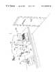
- FIG. 1illustrates a laboratory or testing facility environment.
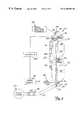
- FIG. 2is a schematic illustration of an embodiment of a rinse device coupled to sample processing components of an analytical instrument.
- FIG. 3is a perspective illustration of an embodiment of a rinse device.
- FIG. 4is an enlarged perspective illustration of autosampler and concentrator units.
- FIG. 5is a detailed view of the autosampler unit with an outer cover removed to illustrate the sample processing components of the unit and rinse device.
- FIG. 6is a cross-sectional view of an embodiment of the rinse device illustrated in FIG. 5 .
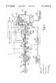
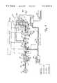
- FIGS. 7-10are simplified schematic illustrations of operation of the rinse device interfaced with sample processing components of an autosampler unit and concentrator unit.
- FIG. 11is a flow diagram of operation of an embodiment of the rinse device.
- FIG. 1illustrates the environment of a version of the invention including a laboratory or research facility 100 and analytical instruments 102 supported on a lab bench 104 .
- the analytical instruments illustrated in FIG. 1include an autosampler 106 and a concentrator 108 .
- the autosampler 106extracts a sample.
- a concentrator 108is coupled to the autosampler 106 to prepare a sample for analysis by a gas chromatograph (not shown) or similar apparatus.
- laboratory facility 100may be equipped with electrical outlets 110 , a gas source 112 and a water source such as tap 114 .
- the analytical instruments 102are connected to the electrical outlets 110 for operating power.
- the autosampler 106is coupled to a gas source 112 for supplying a carrier gas for sampling operation.
- the gas sourcecan be a pressurized inert gas source such as helium.
- the gascan be contained in a standalone tank or can be contained in a permanent gas source structure.
- the analytical instruments 102 showninclude sample processing components 118 as shown in FIGS. 2, 3 , and 5 - 10 .
- the sample processing components 118carry or contain sample for processing and analysis and include sample tubes 122 (FIG. 5 ), and sample flow valves 124 (FIG. 5) and sample metering assembly or devices 126 (FIGS. 7 - 10 ), etc. If residue from a previous sample is left on the sample processing components 118 , a subsequent sample can be contaminated and measurement accuracy of a subsequent sample can be compromised.
- the embodiment in FIG. 2relates to a device for rinsing sample processing components 118 of an analytical instrument 102 to eliminate residue from a prior sample.
- the rinse device 130intermittently supplies rinse fluid to sample processing components 118 of the analytical instruments 102 .
- the rinse device 130includes inlet 132 coupleable to a fluid source 133 , an outlet 134 coupleable to sample processing components 118 of an analytical instrument 102 , a fluid reservoir 138 between the inlet and outlet 132 , 134 , and a heater 140 for heating fluid in the reservoir 138 .
- the reservoir 138includes two reservoir chambers 142 , 144 connected in series and separated by a restricted passageway 148 .
- the fluid source 133such as filtered tap water from water source 114 (FIG. 1 )—filtered through a charcoal filter for example (not shown)—or deionized water from a tank such as a portable tank (not shown) provides rinse fluid heated by device 130 .
- Alternate fluidsmay be used and use of the device is not limited to the specific fluids or mediums disclosed.
- Fluidis delivered to device 130 to elevate the temperature of the fluid within a defined temperature range for rinsing sample processing components 118 . Fluid is delivered from fluid source 133 through inlet 132 to reservoir chamber 142 . Fluid is heated in reservoir chamber 142 . Fluid flows from reservoir chamber 142 through the restricted passageway 148 into reservoir chamber 144 connected in series with reservoir chamber 142 .
- Fluid in reservoir chamber 144is heated and discharged through outlet 134 to sample processing components 118 (including sample tubes 122 , sample flow valves 124 (FIGS. 5 and 7 - 10 ) and sample metering assembly or devices 126 (shown in FIGS. 7-10) of an analytical instrument.
- sample processing components 118including sample tubes 122 , sample flow valves 124 (FIGS. 5 and 7 - 10 ) and sample metering assembly or devices 126 (shown in FIGS. 7-10) of an analytical instrument.
- Analytical instrumentsinclude autosamplers 106 and concentrators 108 as previously explained.
- the embodiment of the rinse device shown in FIGS. 3 and 6,has hollow elongated cylinders 150 , 152 connected by a narrow tube 154 to form reservoir chambers 142 , 144 and restricted passageway 148 .
- the cylinders 150 , 152include an outer cylindrical wall 156 and opposed end walls 158 , 160 (shown in FIG. 6) enclosing an interior chamber 162 (as shown in FIG. 6 ).
- Interior chambers 162 of members 150 , 152form the reservoir chambers 142 , 144 .
- Cylinders 150 , 152can be formed of a metal material able to withstand high temperatures.
- the capacity or volume of chambers 162is sized to hold a sufficient volume of rinse fluid for multiple rinse cycles. For example, a single rinse cycle can require 25-40 milliliters of fluid and the capacity of the combined chambers 162 for cylinders 150 , 152 can hold 140 milliliters of fluid.
- Tube 154includes an inner conduit 163 and opened threaded ends 164 , 166 (shown in FIG. 6 ).
- Conduit 163has a reduced cross-sectional area in comparison to the reservoir chambers 142 , 144 to form the restricted passageway 148 .
- the restricted passageway 148is small enough to separate the reservoir chambers 142 , 144 to limit significant intermixing of fluid so that unheated fluid from fluid source 133 introduced into chamber 142 does not sufficiently mix with fluid in the second reservoir chamber 144 to lower the elevated temperature of the fluid in the second reservoir chamber 144 . Since fluid in reservoir chamber 144 is separated from unheated fluid from fluid source 133 by reservoir chamber 142 and restricted passageway 148 , the temperature of fluid in reservoir chamber 144 is easier to control for better temperature consistency.
- ends 164 , 166 of the tube 154are threadably attached to end walls 158 , 160 of cylinders 150 , 152 so that conduit 163 is opened or fluidly coupled to interior chambers 162 of cylinders 150 , 152 .
- Tube 154is also formed of a material able to withstand high temperatures. The threaded ends 164 , 166 are sealed by a Teflon tape to limit leakage.
- inlet 132 and outlet 134are formed of threaded couplers 170 having a fluid passageway 172 therethrough (shown in FIG. 6 ).
- the threaded couplers 170include opposed threaded ends 174 , 176 .
- Threaded end 176 of the inlet 132is coupled to end wall 158 of cylinder 150 and threaded end 174 is coupled to fluid source 133 via a hose 178 .
- Threaded end 176 of outlet 134is coupled to end wall 160 of cylinder 152 and threaded end 174 is coupleable to sample processing components 118 .
- the threaded ends 174 , 176are sealed by a Teflon tape to limit leakage.
- a pressure relief valve 180is coupled to the reservoir 138 (at inlet 132 ) via hose 178 to relieve pressure build up in the reservoir 138 .
- Heater 140is coupled to and heats each reservoir chamber 142 , 144 as previously illustrated in FIG. 2 .
- heater 140includes first and second conductive sleeves 190 , 192 partially enclosing cylinders 150 , 152 .
- Heating elements in the sleeves 190 , 192are connected in series to a power source 196 via heating circuit 198 to provide an embodiment of heating members coupled to each reservoir chamber 142 , 144 .
- the heating circuit 198includes a first wire 200 coupled between the power source 196 and a heating element in the sleeve 190 .
- a second wire 208is coupled between the heating element in the sleeve 190 and the heating element in sleeve 192 .
- a third wire 204is coupled between the heating element in sleeve 192 and the power source 196 .
- a thermal circuit protector 212is incorporated into the heating circuit 198 preferably between conductive sleeves 190 , 192 to provide a circuit interrupt to protect components of the device from overheating. Although separate heating members are shown connected in series, a single heater or multiple heaters separately connected or connected in parallel could be used in addition to that shown.
- controller 220operates heater 140 to provide adequate heat to maintain fluid temperature within a desired temperature range.
- the heatermay be cycled on to initially heat incoming fluid and cycled off once the fluid is within the desired temperature range.
- a temperature sensor 222is included for heater control.
- the temperature sensor 222senses the temperature in reservoir 138 (cylinder 152 ) in order to regulate the temperature of the fluid within reservoir 138 .
- the temperature sensor 222is coupled to the controller 220 to adjust the energization of heater 140 based upon the sensed temperature.
- Example temperature sensorsinclude a thermistor included as an integrated circuit, a thermocouple or other temperature sensor devices.
- the temperature sensor 222is coupled to reservoir chamber 144 adjacent to or opened to outlet 134 for temperature control.
- FIG. 4is a detailed illustration of an analytical instrument 102 including separate autosampler and concentrator units 106 , 108 having sample processing and operating components housed in cabinets 230 , 232 .
- Autosampler unit 106 shown in FIG. 4measures and delivers the sample to concentrator unit 108 via line 233 coupled to the autosampler unit 106 and concentrator unit 108 .
- these componentscould be constructed as a single unit.
- a cover 234(shown in FIG. 4) enclosing the autosampler unit 106 is removed to illustrate sample processing and other operating components.
- the sample processing componentsinclude sample tubes 122 , sample flow valves 124 , etc.
- the rinse device 130is supported in vertical alignment (generally perpendicular to a support base 235 of the device) via a bracket 236 .
- An insulator member 238surrounds or encloses a portion of the device 130 .
- the insulating member 238is foam, although other insulating materials may be used.
- the insulating member 238 or jacketrestricts heat flow from the device 130 to conserve energy and protect other processing components from overheating.
- FIGS. 7-10are simplified schematic illustrations of an embodiment of components of an autosampler unit 106 (including sample processing components 118 ) and concentrator 108 interfaced with a rinse device 130 .
- Rinse fluidis supplied from rinse device 130 to autosampler 106 and concentrator 108 for rinsing sample processing components 118 as will be explained.
- autosampler 106includes a sampling needle 250 , a standard vial 251 , and valves 254 , 256 , 258 and 260 (forming a valve assembly) as shown in FIGS. 7-10.
- Sampling needle 250extracts sample from vials 252 (shown in FIG. 4) for analysis by a gas chromatograph 253 for example coupled to the concentrator 108 .
- Valve 254includes a normally closed port 262 coupled to rinse device 130 via conduit 264 , a normally opened port 266 coupled to a pressurized carrier source 268 and a common port 270 coupled to a common port 272 of valve 256 .
- Valve 256includes a normally opened port 273 coupled to sampling needle 250 and a normally closed port 274 coupled to valve 258 .
- Valves 258 and 260close ends of a measurement pipette 280 to form a sample metering assembly 126 .
- Valve 258includes port 282 opened to valve 256 , port 284 normally opened to drain 285 and port 286 opened to pipette 280 .
- Valve 260includes port 290 coupled to sampling needle 250 , port 292 opened to pipette 280 and port 294 fluidly coupled to the concentrator 108 .
- FIGS. 7-8illustrate a rinse cycle of the apparatus.
- normally closed port 262 of valve 254is opened to allow rinse fluid to be discharged from device 130 .
- Rinse fluidis directed through sample metering assembly (pipette 280 ) and sampling needle 250 as shown in FIG. 7 and through concentrator 108 as illustrated in FIG. 8 via selective operation of ports 290 , 294 of valve 260 .
- Rinse fluidis discharged to a drain 300 .
- valve port 262is closed and port 266 is opened for continued sampling operation.
- normally closed port 273 of valve 256is opened to supply pressure to sampling needle 250 to extract a sample.
- Valve port 290is opened to fill pipette 280 for measurement as shown in FIG. 9 .
- Standard 251is supplied to concentrator 108 and port 282 is opened to carrier gas source 268 to empty sample from pipette 280 to concentrator 108 .
- valves 254 , 256 , 258 and 260Operation of valves 254 , 256 , 258 and 260 is controlled by controller 220 for continuous automated sampling operation and intermittent rinsing. Operation of valves 254 , 256 , 258 and 260 for various operations is summarized in the table below. The table identifies the opened valve ports for valves 254 , 256 , 258 and 260 for various operations. As illustrated, there are two rinse modes, RINSE I and RINSE II. During RINSE I (FIG. 7 ), sampling needle 250 is rinsed and during RINSE II FIG. 8 ), rinse fluid is supplied to the concentrator 108 .
- fluidis supplied to a first reservoir chamber 142 from a fluid source 133 and heated as illustrated by blocks 350 , 352 .
- Fluid from the first reservoir chamber 142is supplied to the second reservoir chamber 144 through the restricted passageway 148 and heated as illustrated by blocks 354 , 356
- Fluid from the second reservoir chamber 144is discharged (via port 262 of valve 254 ) to rinse sample processing components as illustrated by block 358 .
- the reservoir chambersare normally opened to the fluid source 133 and fluid is concurrently heated in the reservoir chambers 142 , 144 . Fluid is maintained in the reservoir chambers via valve 254 until needed for a rinse cycle after a sampling cycle.
- fluid in the desired temperature rangeis available in the reservoir chambers and intermittently discharged for a rinse cycle when port 262 of valve 254 is opened.
- fluid from source 133normally open to the reservoir
- reservoir chamber 142fluid from source 133 (normally open to the reservoir) flows into reservoir chamber 142 to fill a portion of the reservoir emptied to replenish fluid in the reservoir so that fluid is available for a subsequent rinse cycle. Since fluid is heated in multi-reservoir chambers, better temperature consistency is achieved.
Landscapes
- Chemical & Material Sciences (AREA)
- Health & Medical Sciences (AREA)
- General Health & Medical Sciences (AREA)
- Life Sciences & Earth Sciences (AREA)
- Analytical Chemistry (AREA)
- Biochemistry (AREA)
- Physics & Mathematics (AREA)
- General Physics & Mathematics (AREA)
- Immunology (AREA)
- Pathology (AREA)
- Engineering & Computer Science (AREA)
- Mechanical Engineering (AREA)
- Clinical Laboratory Science (AREA)
- Chemical Kinetics & Catalysis (AREA)
- Sampling And Sample Adjustment (AREA)
Abstract
Description
The present invention relates to analytical instruments. In particular, the present invention relates to a rinsing device coupleable to an analytical instrument for rinsing sample processing components of the analytical instrument.
Analytical instruments are known which analyze various attributes of samples including liquid samples, such as drinking water or waste water samples and solid samples such as soil samples or gas samples. For example, such instruments may measure carbon content in water samples or volatile organic compounds (VOC) in soil samples.
Analytical instruments include autosamplers for systematically extracting samples for analysis, as well as purge and trap concentrators which are used with a liquid sample to prepare a gaseous sample for analysis by another analytical instrument such as a gas chromatograph. Such instruments may be connected for continuous operation for extracting, processing and analyzing samples.
During operation of an analytical instrument, sample may flow through sample processing components to extract a sample and process the sample for analysis. It is important to maintain a virgin sample for accurate measurement and analysis results. However, residue from prior samples can be deposited on the sample processing components and can be introduced in a subsequent sample thus contaminating the analysis of the subsequent sample. Thus it is desirable to remove residue from the sampling processing components prior to a subsequent testing cycle.
The present invention relates to a rinse device which intermittently provides heated rinsing fluid to the sample processing components for rinsing residue from a prior sampling cycle. The rinse device is a multi-stage heating apparatus including first and second reservoir chambers separated by a restricted passageway. Fluid is sequentially heated by the first and second reservoir chambers for discharge to rinse sampling processing components of an analytical instrument. The multi-stage heater improves temperature control for better temperature consistency for rinsing applications.
In one embodiment of the rinse device the reservoir includes a temperature sensor for controlling the temperature of the rinse fluid within the reservoir chambers. The sensor is coupled to a controller for energizing the heat source so that the temperature of the fluid in the reservoir is maintained within a desired temperature range for optimum effectiveness.
FIG. 1 illustrates a laboratory or testing facility environment.
FIG. 2 is a schematic illustration of an embodiment of a rinse device coupled to sample processing components of an analytical instrument.
FIG. 3 is a perspective illustration of an embodiment of a rinse device.
FIG. 4 is an enlarged perspective illustration of autosampler and concentrator units.
FIG. 5 is a detailed view of the autosampler unit with an outer cover removed to illustrate the sample processing components of the unit and rinse device.
FIG. 6 is a cross-sectional view of an embodiment of the rinse device illustrated in FIG.5.
FIGS. 7-10 are simplified schematic illustrations of operation of the rinse device interfaced with sample processing components of an autosampler unit and concentrator unit.
FIG. 11 is a flow diagram of operation of an embodiment of the rinse device.
FIG. 1 illustrates the environment of a version of the invention including a laboratory orresearch facility 100 andanalytical instruments 102 supported on alab bench 104. The analytical instruments illustrated in FIG. 1 include anautosampler 106 and aconcentrator 108. Theautosampler 106 extracts a sample. Aconcentrator 108 is coupled to theautosampler 106 to prepare a sample for analysis by a gas chromatograph (not shown) or similar apparatus.
As shown,laboratory facility 100 may be equipped withelectrical outlets 110, a gas source112 and a water source such astap 114. Theanalytical instruments 102 are connected to theelectrical outlets 110 for operating power. Theautosampler 106 is coupled to a gas source112 for supplying a carrier gas for sampling operation. The gas source can be a pressurized inert gas source such as helium. The gas can be contained in a standalone tank or can be contained in a permanent gas source structure.
Accurate analysis depends upon the integrity of the sample extracted, processed and delivered to the test apparatus for analysis. Theanalytical instruments 102 shown includesample processing components 118 as shown in FIGS. 2,3, and5-10. Thesample processing components 118 carry or contain sample for processing and analysis and include sample tubes122 (FIG.5), and sample flow valves124 (FIG. 5) and sample metering assembly or devices126 (FIGS.7-10), etc. If residue from a previous sample is left on thesample processing components 118, a subsequent sample can be contaminated and measurement accuracy of a subsequent sample can be compromised.
The embodiment in FIG. 2 relates to a device for rinsingsample processing components 118 of ananalytical instrument 102 to eliminate residue from a prior sample. Therinse device 130 intermittently supplies rinse fluid tosample processing components 118 of theanalytical instruments 102. Therinse device 130 includesinlet 132 coupleable to afluid source 133, anoutlet 134 coupleable tosample processing components 118 of ananalytical instrument 102, afluid reservoir 138 between the inlet andoutlet heater 140 for heating fluid in thereservoir 138. As shown, thereservoir 138 includes tworeservoir chambers passageway 148.
Thefluid source 133 such as filtered tap water from water source114 (FIG.1)—filtered through a charcoal filter for example (not shown)—or deionized water from a tank such as a portable tank (not shown) provides rinse fluid heated bydevice 130. Alternate fluids may be used and use of the device is not limited to the specific fluids or mediums disclosed. Fluid is delivered todevice 130 to elevate the temperature of the fluid within a defined temperature range for rinsingsample processing components 118. Fluid is delivered fromfluid source 133 throughinlet 132 toreservoir chamber 142. Fluid is heated inreservoir chamber 142. Fluid flows fromreservoir chamber 142 through therestricted passageway 148 intoreservoir chamber 144 connected in series withreservoir chamber 142. Fluid inreservoir chamber 144 is heated and discharged throughoutlet 134 to sample processing components118 (includingsample tubes 122, sample flow valves124 (FIGS.5 and7-10) and sample metering assembly or devices126 (shown in FIGS. 7-10) of an analytical instrument. Analytical instruments includeautosamplers 106 andconcentrators 108 as previously explained.
The embodiment of the rinse device shown in FIGS. 3 and 6, has hollowelongated cylinders narrow tube 154 toform reservoir chambers passageway 148. In particular, thecylinders cylindrical wall 156 and opposedend walls 158,160 (shown in FIG. 6) enclosing an interior chamber162 (as shown in FIG.6).Interior chambers 162 ofmembers reservoir chambers Cylinders chambers 162 is sized to hold a sufficient volume of rinse fluid for multiple rinse cycles. For example, a single rinse cycle can require 25-40 milliliters of fluid and the capacity of the combinedchambers 162 forcylinders
Tube154 includes aninner conduit 163 and opened threaded ends164,166 (shown in FIG.6).Conduit 163 has a reduced cross-sectional area in comparison to thereservoir chambers passageway 148. Therestricted passageway 148 is small enough to separate thereservoir chambers fluid source 133 introduced intochamber 142 does not sufficiently mix with fluid in thesecond reservoir chamber 144 to lower the elevated temperature of the fluid in thesecond reservoir chamber 144. Since fluid inreservoir chamber 144 is separated from unheated fluid fromfluid source 133 byreservoir chamber 142 and restrictedpassageway 148, the temperature of fluid inreservoir chamber 144 is easier to control for better temperature consistency.
In the embodiment shown in FIG. 6,ends 164,166 of thetube 154 are threadably attached toend walls cylinders conduit 163 is opened or fluidly coupled tointerior chambers 162 ofcylinders
In the embodiment shown in FIG. 3,inlet 132 andoutlet 134 are formed of threadedcouplers 170 having afluid passageway 172 therethrough (shown in FIG.6). The threadedcouplers 170 include opposed threaded ends174,176. Threadedend 176 of theinlet 132 is coupled to endwall 158 ofcylinder 150 and threadedend 174 is coupled tofluid source 133 via ahose 178. Threadedend 176 ofoutlet 134 is coupled to endwall 160 ofcylinder 152 and threadedend 174 is coupleable to sample processingcomponents 118. The threaded ends174,176 are sealed by a Teflon tape to limit leakage. In the embodiment shown in FIG. 3, apressure relief valve 180 is coupled to the reservoir138 (at inlet132) viahose 178 to relieve pressure build up in thereservoir 138.
In the embodiment of the rinse device illustrated in FIG. 3, operation of theheater 140 is controlled by acontroller 220.Controller 220 operatesheater 140 to provide adequate heat to maintain fluid temperature within a desired temperature range. The heater may be cycled on to initially heat incoming fluid and cycled off once the fluid is within the desired temperature range. In the embodiment shown atemperature sensor 222 is included for heater control.
Thetemperature sensor 222 senses the temperature in reservoir138 (cylinder152) in order to regulate the temperature of the fluid withinreservoir 138. Thetemperature sensor 222 is coupled to thecontroller 220 to adjust the energization ofheater 140 based upon the sensed temperature.
If the temperature is outside a predefined temperature range, the energization of theheater 130 is either increased or decreased to adjust the temperature of fluid in thereservoir 138 within the desired temperature range. The desired temperature range is below the boiling point of a rinsing fluid so that steam is not supplied to rinse thesample processing components 118. Example temperature sensors include a thermistor included as an integrated circuit, a thermocouple or other temperature sensor devices. Thetemperature sensor 222 is coupled toreservoir chamber 144 adjacent to or opened tooutlet 134 for temperature control.
As described,reservoir chambers fluid source 133 for discharge to sample processingcomponents 118. FIG. 4 is a detailed illustration of ananalytical instrument 102 including separate autosampler andconcentrator units cabinets Autosampler unit 106 shown in FIG. 4 measures and delivers the sample toconcentrator unit 108 vialine 233 coupled to theautosampler unit 106 andconcentrator unit 108. Although shown as separate units, these components could be constructed as a single unit.
In FIG. 5, a cover234 (shown in FIG. 4) enclosing theautosampler unit 106 is removed to illustrate sample processing and other operating components. As previously explained, the sample processing components includesample tubes 122,sample flow valves 124, etc. In the embodiment shown, the rinsedevice 130 is supported in vertical alignment (generally perpendicular to asupport base 235 of the device) via abracket 236. Aninsulator member 238 surrounds or encloses a portion of thedevice 130. In one embodiment the insulatingmember 238 is foam, although other insulating materials may be used. The insulatingmember 238 or jacket restricts heat flow from thedevice 130 to conserve energy and protect other processing components from overheating.
FIGS. 7-10 are simplified schematic illustrations of an embodiment of components of an autosampler unit106 (including sample processing components118) andconcentrator 108 interfaced with a rinsedevice 130. Rinse fluid is supplied from rinsedevice 130 toautosampler 106 andconcentrator 108 for rinsingsample processing components 118 as will be explained. As shown,autosampler 106 includes asampling needle 250, astandard vial 251, andvalves needle 250 extracts sample from vials252 (shown in FIG. 4) for analysis by agas chromatograph 253 for example coupled to theconcentrator 108.
FIGS. 7-8 illustrate a rinse cycle of the apparatus. As shown, during a rinse cycle, normally closedport 262 ofvalve 254 is opened to allow rinse fluid to be discharged fromdevice 130. Rinse fluid is directed through sample metering assembly (pipette280) andsampling needle 250 as shown in FIG.7 and throughconcentrator 108 as illustrated in FIG. 8 via selective operation ofports valve 260. Rinse fluid is discharged to adrain 300.
After completion of a rinsecycle valve port 262 is closed andport 266 is opened for continued sampling operation. During a sampling operation, normally closedport 273 ofvalve 256 is opened to supply pressure tosampling needle 250 to extract a sample.Valve port 290 is opened to fillpipette 280 for measurement as shown in FIG.9.Standard 251 is supplied toconcentrator 108 andport 282 is opened tocarrier gas source 268 to empty sample frompipette 280 toconcentrator 108.
Operation ofvalves controller 220 for continuous automated sampling operation and intermittent rinsing. Operation ofvalves valves sampling needle 250 is rinsed and during RINSE II FIG.8), rinse fluid is supplied to theconcentrator 108.
| OPEN PORT ON VALVE |
| VALVE | VALVE | VALVE | VALVE | FIG. | |
| 254 | 256 | 258 | 260 | NO. | |
| RINSE I | 262 | 274 | 282 | 290 | FIG. 7 |
| RINSE | 262 | 274 | 282 | 294 | FIG. 8 |
| 266 | 273 | 284 | 290 | FIG. 9 | |
| 266 | 274 | 282 | 294 | FIG. 10 | |
| PURGE | |||||
As illustrated in FIG. 11, in operation, fluid is supplied to afirst reservoir chamber 142 from afluid source 133 and heated as illustrated byblocks first reservoir chamber 142 is supplied to thesecond reservoir chamber 144 through the restrictedpassageway 148 and heated as illustrated byblocks second reservoir chamber 144 is discharged (viaport 262 of valve254) to rinse sample processing components as illustrated byblock 358. In an embodiment, the reservoir chambers are normally opened to thefluid source 133 and fluid is concurrently heated in thereservoir chambers valve 254 until needed for a rinse cycle after a sampling cycle.
On demand, fluid in the desired temperature range is available in the reservoir chambers and intermittently discharged for a rinse cycle whenport 262 ofvalve 254 is opened. As fluid is discharged from the reservoir138 (chamber144), fluid from source133 (normally open to the reservoir) flows intoreservoir chamber 142 to fill a portion of the reservoir emptied to replenish fluid in the reservoir so that fluid is available for a subsequent rinse cycle. Since fluid is heated in multi-reservoir chambers, better temperature consistency is achieved.
Although the present invention has been described with reference to preferred embodiments, workers skilled in the art will recognize that changes may be made in form and detail without departing from the spirit and scope of the invention.
Claims (12)
1. An analytical instrument comprising:
a cabinet;
sample processing components operably coupled to the cabinet;
a fluid rinse device including an inlet and an outlet, the inlet being coupleable to a fluid source and the outlet being coupleable to the sample processing components;
wherein the fluid rinse device includes a reservoir having at least two reservoir chambers connected in series and separated by a restricted passageway and a heater being disposed about an exterior of each reservoir chamber for heating fluid in the reservoir chamber;
a valve assembly coupleable to a pressurized carrier source, the fluid rinse device, and sample processing components; and
a controller coupled to the valve assembly to intermittently supply fluid to rinse the sample processing components.
2. The analytical instrument of claim1 and including a bracket coupleable to the cabinet and adapted to support the fluid rinse device in vertical alignment generally perpendicular to a support base of the device.
3. The analytical instrument of claim1 including an insulating member surrounding a portion of the fluid rinse device.
4. The analytical instrument of claim1 wherein the sample processing components include a sample metering assembly.
5. The analytical instrument of claim1 wherein the sample processing components includes a sample tube.
6. The analytical instrument of claim1 wherein the sample processing components include a sample flow valve.
7. The analytical instrument of claim1 wherein the sample processing components include a sampling needle.
8. The analytical instrument of claim1 wherein the valve assembly comprises:
a first port coupleable to the fluid rinse device;
a second port coupleable to a pressurized carrier source; and
an outlet port coupleable to the sample processing components wherein the controller operates the valve assembly to intermittently open and close the first and second ports.
9. The analytical instrument of claim8 wherein the valve assembly includes an outlet port coupleable to a concentrator.
10. An analytical instrument comprising:
a cabinet;
sample processing components operably coupled to the cabinet;
a fluid rinse device including an inlet and an outlet, the inlet being coupleable to a fluid source and the outlet being coupleable to the sample processing components;
wherein the fluid rinse device includes a reservoir having at least two reservoir chambers connected in series and separated by a restricted passageway and a heater being coupled to each reservoir chamber for heating fluid in the reservoir chamber;
a valve assembly coupleable to the fluid rinse device, a pressurized carrier source and the sample processing components, the valve assembly including: a first port coupleable to the fluid rinse device;
a second port coupleable to a pressurized carrier source; and
an outlet port coupleable to the sample processing components wherein the controller operates the valve assembly to intermittently open and close the first and second ports; and
a controller coupled to the valve assembly to intermittently supply fluid to rinse the sample processing components.
11. The analytical instrument of claim10 wherein the sample processing components include a sample metering assembly and the valve assembly includes an outlet port coupleable to the sample metering assembly.
12. The analytical instrument of claim10 wherein the sample processing components include a sampling needle and the valve assembly includes an outlet port coupleable to the sampling needle.
Priority Applications (1)
| Application Number | Priority Date | Filing Date | Title |
|---|---|---|---|
| US09/195,330US6280688B1 (en) | 1998-11-18 | 1998-11-18 | Rinsing device for sample processing components of an analytical instrument |
Applications Claiming Priority (1)
| Application Number | Priority Date | Filing Date | Title |
|---|---|---|---|
| US09/195,330US6280688B1 (en) | 1998-11-18 | 1998-11-18 | Rinsing device for sample processing components of an analytical instrument |
Publications (1)
| Publication Number | Publication Date |
|---|---|
| US6280688B1true US6280688B1 (en) | 2001-08-28 |
Family
ID=22721003
Family Applications (1)
| Application Number | Title | Priority Date | Filing Date |
|---|---|---|---|
| US09/195,330Expired - LifetimeUS6280688B1 (en) | 1998-11-18 | 1998-11-18 | Rinsing device for sample processing components of an analytical instrument |
Country Status (1)
| Country | Link |
|---|---|
| US (1) | US6280688B1 (en) |
Cited By (11)
| Publication number | Priority date | Publication date | Assignee | Title |
|---|---|---|---|---|
| US6470760B2 (en)* | 1998-06-29 | 2002-10-29 | Nec Corporation | Method and apparatus for automatically analyzing trace substance |
| US20030108454A1 (en)* | 1996-11-12 | 2003-06-12 | Brockwell Timothy Graham | Sample vial and vial closure device for use in gas analysis and method of using the same |
| US20050236022A1 (en)* | 2004-04-21 | 2005-10-27 | Bailiff Bobby D | Ostomy bag cleaning device |
| US20080017724A1 (en)* | 2006-07-19 | 2008-01-24 | Aos Holding Company | Water heating distribution system |
| CN104614542A (en)* | 2013-11-04 | 2015-05-13 | 上海阔思电子有限公司 | Circulating water concentration monitoring online drainage apparatus |
| US20150226452A1 (en)* | 2012-08-13 | 2015-08-13 | N&W Global Vending S.P.A. | Storage boiler |
| US9234678B1 (en)* | 2011-09-27 | 2016-01-12 | Rheem Manufacturing Company | Stackable water heater apparatus |
| CN112547699A (en)* | 2020-11-13 | 2021-03-26 | 苏州长光华医生物医学工程有限公司 | Avoid cleaning structure of sample needle hanging liquid |
| US11047779B2 (en) | 2017-12-04 | 2021-06-29 | Montana Instruments Corporation | Analytical instruments, methods, and components |
| US11956924B1 (en) | 2020-08-10 | 2024-04-09 | Montana Instruments Corporation | Quantum processing circuitry cooling systems and methods |
| US12181202B2 (en) | 2019-06-04 | 2024-12-31 | Montana Instruments Corporation | Thermal connection assemblies and methods |
Citations (25)
| Publication number | Priority date | Publication date | Assignee | Title |
|---|---|---|---|---|
| US1717207A (en) | 1927-12-28 | 1929-06-11 | Edison Electric Appliance Co | Electric water heater |
| US2386949A (en) | 1943-11-09 | 1945-10-16 | Henry W Hayward | Liquid heater |
| US2594616A (en) | 1948-10-04 | 1952-04-29 | Blondeau Benjamin Howard | Hot-water heating device and method |
| US2607878A (en) | 1950-08-08 | 1952-08-19 | Leslie G Bowen | Electric liquid heater |
| US2779855A (en) | 1955-06-14 | 1957-01-29 | Boyd F Sawyer | Automatic electrically operated water heater |
| US2834865A (en) | 1957-07-17 | 1958-05-13 | Sydney N Coates | Two-compartment hot water tank |
| US3383495A (en) | 1967-04-28 | 1968-05-14 | Singer Co | Hot water heating systems |
| US3484580A (en) | 1967-08-25 | 1969-12-16 | Patterson Kelley Co | Water heating system |
| US3568589A (en)* | 1969-07-24 | 1971-03-09 | Romarico Robau | Coffee brewing apparatus |
| US3787659A (en) | 1971-08-17 | 1974-01-22 | Olland Industrie Nv | Apparatus for supplying either hot or warm water in a vending machine |
| US3945411A (en)* | 1974-04-01 | 1976-03-23 | Mojonnier Bros. Co. | System for mixing various kinds of fluids for producing beverages, and means for cleaning the apparatus between operations |
| US4310010A (en)* | 1980-01-07 | 1982-01-12 | Svoboda Melora J | Apparatus for cleaning closed-end tubes |
| US4323760A (en)* | 1979-12-13 | 1982-04-06 | Milliken Research Corporation | Method and apparatus for temperature control of heated fluid in a fluid handling system |
| US4514617A (en)* | 1983-01-19 | 1985-04-30 | Haim Amit | Two-stage electric water heater |
| US4575615A (en) | 1984-05-29 | 1986-03-11 | Toshiba Electric Appliances Co., Ltd. | Hot water supplying device |
| US4835365A (en)* | 1986-09-29 | 1989-05-30 | Etheridge David R | De-ionized fluid heater and control system |
| US4858155A (en)* | 1985-12-24 | 1989-08-15 | Beckman Instruments, Inc. | Reaction temperature control system |
| US5042293A (en)* | 1989-09-25 | 1991-08-27 | Heyde H Paul | Ion chromatography method for low concentrations |
| US5108705A (en)* | 1990-03-12 | 1992-04-28 | Thermedics Inc. | Vapor detection with high speed gas chromatography |
| US5324480A (en)* | 1992-12-04 | 1994-06-28 | Hamilton Company | Liquid handling system |
| US5387334A (en)* | 1991-02-15 | 1995-02-07 | Toa Medical Electronics Co., Ltd. | Apparatus for regulating liquid temperature |
| US5447077A (en)* | 1992-04-30 | 1995-09-05 | Mls Mikrowellen-Labor-Systeme Gmbh | Device for the evaporation treatment of preferably liquid substances, in particular reagents, or for the preparation or analysis of sample material |
| US5712951A (en) | 1995-10-24 | 1998-01-27 | Chou; Martin | Electric water heater with primary and secondary pre-heatng chambers |
| US5753195A (en)* | 1996-01-02 | 1998-05-19 | Kew Import/Export Inc. | Cleaning and sterilizing mechanism |
| US5858114A (en)* | 1993-10-29 | 1999-01-12 | Board; Alan Edwin | Method and apparatus for cleaning liquid dispensing systems |
- 1998
- 1998-11-18USUS09/195,330patent/US6280688B1/ennot_activeExpired - Lifetime
Patent Citations (25)
| Publication number | Priority date | Publication date | Assignee | Title |
|---|---|---|---|---|
| US1717207A (en) | 1927-12-28 | 1929-06-11 | Edison Electric Appliance Co | Electric water heater |
| US2386949A (en) | 1943-11-09 | 1945-10-16 | Henry W Hayward | Liquid heater |
| US2594616A (en) | 1948-10-04 | 1952-04-29 | Blondeau Benjamin Howard | Hot-water heating device and method |
| US2607878A (en) | 1950-08-08 | 1952-08-19 | Leslie G Bowen | Electric liquid heater |
| US2779855A (en) | 1955-06-14 | 1957-01-29 | Boyd F Sawyer | Automatic electrically operated water heater |
| US2834865A (en) | 1957-07-17 | 1958-05-13 | Sydney N Coates | Two-compartment hot water tank |
| US3383495A (en) | 1967-04-28 | 1968-05-14 | Singer Co | Hot water heating systems |
| US3484580A (en) | 1967-08-25 | 1969-12-16 | Patterson Kelley Co | Water heating system |
| US3568589A (en)* | 1969-07-24 | 1971-03-09 | Romarico Robau | Coffee brewing apparatus |
| US3787659A (en) | 1971-08-17 | 1974-01-22 | Olland Industrie Nv | Apparatus for supplying either hot or warm water in a vending machine |
| US3945411A (en)* | 1974-04-01 | 1976-03-23 | Mojonnier Bros. Co. | System for mixing various kinds of fluids for producing beverages, and means for cleaning the apparatus between operations |
| US4323760A (en)* | 1979-12-13 | 1982-04-06 | Milliken Research Corporation | Method and apparatus for temperature control of heated fluid in a fluid handling system |
| US4310010A (en)* | 1980-01-07 | 1982-01-12 | Svoboda Melora J | Apparatus for cleaning closed-end tubes |
| US4514617A (en)* | 1983-01-19 | 1985-04-30 | Haim Amit | Two-stage electric water heater |
| US4575615A (en) | 1984-05-29 | 1986-03-11 | Toshiba Electric Appliances Co., Ltd. | Hot water supplying device |
| US4858155A (en)* | 1985-12-24 | 1989-08-15 | Beckman Instruments, Inc. | Reaction temperature control system |
| US4835365A (en)* | 1986-09-29 | 1989-05-30 | Etheridge David R | De-ionized fluid heater and control system |
| US5042293A (en)* | 1989-09-25 | 1991-08-27 | Heyde H Paul | Ion chromatography method for low concentrations |
| US5108705A (en)* | 1990-03-12 | 1992-04-28 | Thermedics Inc. | Vapor detection with high speed gas chromatography |
| US5387334A (en)* | 1991-02-15 | 1995-02-07 | Toa Medical Electronics Co., Ltd. | Apparatus for regulating liquid temperature |
| US5447077A (en)* | 1992-04-30 | 1995-09-05 | Mls Mikrowellen-Labor-Systeme Gmbh | Device for the evaporation treatment of preferably liquid substances, in particular reagents, or for the preparation or analysis of sample material |
| US5324480A (en)* | 1992-12-04 | 1994-06-28 | Hamilton Company | Liquid handling system |
| US5858114A (en)* | 1993-10-29 | 1999-01-12 | Board; Alan Edwin | Method and apparatus for cleaning liquid dispensing systems |
| US5712951A (en) | 1995-10-24 | 1998-01-27 | Chou; Martin | Electric water heater with primary and secondary pre-heatng chambers |
| US5753195A (en)* | 1996-01-02 | 1998-05-19 | Kew Import/Export Inc. | Cleaning and sterilizing mechanism |
Cited By (25)
| Publication number | Priority date | Publication date | Assignee | Title |
|---|---|---|---|---|
| US20030108454A1 (en)* | 1996-11-12 | 2003-06-12 | Brockwell Timothy Graham | Sample vial and vial closure device for use in gas analysis and method of using the same |
| US6470760B2 (en)* | 1998-06-29 | 2002-10-29 | Nec Corporation | Method and apparatus for automatically analyzing trace substance |
| US20050236022A1 (en)* | 2004-04-21 | 2005-10-27 | Bailiff Bobby D | Ostomy bag cleaning device |
| US20080017724A1 (en)* | 2006-07-19 | 2008-01-24 | Aos Holding Company | Water heating distribution system |
| US7644686B2 (en)* | 2006-07-19 | 2010-01-12 | Aos Holding Company | Water heating distribution system |
| US20100077969A1 (en)* | 2006-07-19 | 2010-04-01 | Aos Holding Company | Method of water heating and distribution |
| US9234678B1 (en)* | 2011-09-27 | 2016-01-12 | Rheem Manufacturing Company | Stackable water heater apparatus |
| US9835359B1 (en) | 2011-09-27 | 2017-12-05 | Rheem Manufacturing Company | Stackable water heater apparatus |
| US20150226452A1 (en)* | 2012-08-13 | 2015-08-13 | N&W Global Vending S.P.A. | Storage boiler |
| US10077919B2 (en)* | 2012-08-13 | 2018-09-18 | N&W Global Vending S.P.A. | Storage boiler |
| CN104614542A (en)* | 2013-11-04 | 2015-05-13 | 上海阔思电子有限公司 | Circulating water concentration monitoring online drainage apparatus |
| US11047779B2 (en) | 2017-12-04 | 2021-06-29 | Montana Instruments Corporation | Analytical instruments, methods, and components |
| US20220155194A1 (en)* | 2017-12-04 | 2022-05-19 | Montana Instruments Corporation | Analytical Instruments, Methods, and Components |
| US11125664B2 (en) | 2017-12-04 | 2021-09-21 | Montana Instruments Corporation | Analytical instruments, methods, and components |
| US11150169B2 (en)* | 2017-12-04 | 2021-10-19 | Montana Instruments Corporation | Analytical instruments, methods, and components |
| US11248996B2 (en)* | 2017-12-04 | 2022-02-15 | Montana Instruments Corporation | Analytical instruments, methods, and components |
| US11275000B2 (en)* | 2017-12-04 | 2022-03-15 | Montana Instruments Corporation | Analytical instruments, methods, and components |
| US12360025B2 (en)* | 2017-12-04 | 2025-07-15 | Montana Instruments Corporation | Analytical instruments, methods, and components |
| US20240230489A1 (en)* | 2017-12-04 | 2024-07-11 | Montana Instruments Corporation | Analytical Instruments, Methods, and Components |
| US11927515B2 (en)* | 2017-12-04 | 2024-03-12 | Montana Instruments Corporation | Analytical instruments, methods, and components |
| US12181202B2 (en) | 2019-06-04 | 2024-12-31 | Montana Instruments Corporation | Thermal connection assemblies and methods |
| US11956924B1 (en) | 2020-08-10 | 2024-04-09 | Montana Instruments Corporation | Quantum processing circuitry cooling systems and methods |
| US12262510B2 (en) | 2020-08-10 | 2025-03-25 | Montana Instruments Corporation | Quantum processing circuitry cooling systems and methods |
| CN112547699A (en)* | 2020-11-13 | 2021-03-26 | 苏州长光华医生物医学工程有限公司 | Avoid cleaning structure of sample needle hanging liquid |
| CN112547699B (en)* | 2020-11-13 | 2022-04-12 | 苏州长光华医生物医学工程有限公司 | Avoid cleaning structure of sample needle hanging liquid |
Similar Documents
| Publication | Publication Date | Title |
|---|---|---|
| US6280688B1 (en) | Rinsing device for sample processing components of an analytical instrument | |
| JP3373232B2 (en) | Supercritical fluid extraction device | |
| US4966695A (en) | High pressure liquid chromatography column jacket | |
| US4086061A (en) | Temperature control system for chemical reaction cell | |
| US4044593A (en) | Chromatograph | |
| US5398806A (en) | Apparatus for performing a plurality of distillation and reflux operations simultaneously within a compact space | |
| US6007777A (en) | Liquid sample carbon analyzer | |
| WO1998011432A1 (en) | Analytical engine for gas chromatograph | |
| US5032362A (en) | Analyzing apparatus | |
| US6055845A (en) | Method for applying samples to be analyzed by gas chromatography and sampling tube | |
| US6149869A (en) | Chemical synthesizers | |
| KR19990082146A (en) | Moisture analyzer | |
| US6046450A (en) | Reduction furnace for quantitative deuterium determination in hydrogen-containing samples | |
| US20030062067A1 (en) | Closed cell washer | |
| KR200492724Y1 (en) | Apparatus for measuring fluorine | |
| CN111033213B (en) | Apparatus and method for partial conversion of a fluid sample comprising a plurality of components and method for on-line determination and analysis of these components | |
| JP4653286B2 (en) | Assemblies for detaching sampling vials, adapters and sampling vials explicitly intended for said assemblies, and parts kit for forming said assemblies | |
| CN107290463A (en) | A kind of portable purge and trap sampler | |
| CN113663978B (en) | Vacuum ultrasonic bottle washing machine | |
| US4240472A (en) | Apparatus for cleaning and coating capillary tubes useful in gas chromatography | |
| US4399101A (en) | Stopped-flow apparatus | |
| RU2126148C1 (en) | Device feeding samples for gas analysis | |
| US8357340B2 (en) | Materials analysis | |
| CN105277732A (en) | Multifunctional continuous sample injector used for analysis instrument | |
| CN110632233A (en) | Constant temperature chromatographic device |
Legal Events
| Date | Code | Title | Description |
|---|---|---|---|
| AS | Assignment | Owner name:TEKMAR COMPANY, OHIO Free format text:ASSIGNMENT OF ASSIGNORS INTEREST;ASSIGNOR:MOTZ, MARTIN;REEL/FRAME:010040/0097 Effective date:19990602 | |
| STCF | Information on status: patent grant | Free format text:PATENTED CASE | |
| AS | Assignment | Owner name:TELEDYNE TEKMAR COMPANY, OHIO Free format text:CHANGE OF NAME;ASSIGNOR:TEKMAR COMPANY;REEL/FRAME:014186/0276 Effective date:20030519 | |
| FEPP | Fee payment procedure | Free format text:PAYOR NUMBER ASSIGNED (ORIGINAL EVENT CODE: ASPN); ENTITY STATUS OF PATENT OWNER: LARGE ENTITY | |
| FPAY | Fee payment | Year of fee payment:4 | |
| FPAY | Fee payment | Year of fee payment:8 | |
| AS | Assignment | Owner name:TELEDYNE INSTRUMENTS, INC., CALIFORNIA Free format text:MERGER;ASSIGNOR:TELEDYNE TEKMAR COMPANY;REEL/FRAME:027576/0073 Effective date:20111221 | |
| FPAY | Fee payment | Year of fee payment:12 |