US6280472B1 - Apparatus and method for tibial fixation of soft tissue - Google Patents
Apparatus and method for tibial fixation of soft tissueDownload PDFInfo
- Publication number
- US6280472B1 US6280472B1US09/356,959US35695999AUS6280472B1US 6280472 B1US6280472 B1US 6280472B1US 35695999 AUS35695999 AUS 35695999AUS 6280472 B1US6280472 B1US 6280472B1
- Authority
- US
- United States
- Prior art keywords
- guide
- counterbore
- tunnel
- graft
- bone
- Prior art date
- Legal status (The legal status is an assumption and is not a legal conclusion. Google has not performed a legal analysis and makes no representation as to the accuracy of the status listed.)
- Expired - Lifetime
Links
Images


Classifications
- A—HUMAN NECESSITIES
- A61—MEDICAL OR VETERINARY SCIENCE; HYGIENE
- A61F—FILTERS IMPLANTABLE INTO BLOOD VESSELS; PROSTHESES; DEVICES PROVIDING PATENCY TO, OR PREVENTING COLLAPSING OF, TUBULAR STRUCTURES OF THE BODY, e.g. STENTS; ORTHOPAEDIC, NURSING OR CONTRACEPTIVE DEVICES; FOMENTATION; TREATMENT OR PROTECTION OF EYES OR EARS; BANDAGES, DRESSINGS OR ABSORBENT PADS; FIRST-AID KITS
- A61F2/00—Filters implantable into blood vessels; Prostheses, i.e. artificial substitutes or replacements for parts of the body; Appliances for connecting them with the body; Devices providing patency to, or preventing collapsing of, tubular structures of the body, e.g. stents
- A61F2/02—Prostheses implantable into the body
- A61F2/08—Muscles; Tendons; Ligaments
- A61F2/0811—Fixation devices for tendons or ligaments
- A—HUMAN NECESSITIES
- A61—MEDICAL OR VETERINARY SCIENCE; HYGIENE
- A61B—DIAGNOSIS; SURGERY; IDENTIFICATION
- A61B17/00—Surgical instruments, devices or methods
- A61B17/064—Surgical staples, i.e. penetrating the tissue
- A61B17/0642—Surgical staples, i.e. penetrating the tissue for bones, e.g. for osteosynthesis or connecting tendon to bone
- A—HUMAN NECESSITIES
- A61—MEDICAL OR VETERINARY SCIENCE; HYGIENE
- A61B—DIAGNOSIS; SURGERY; IDENTIFICATION
- A61B17/00—Surgical instruments, devices or methods
- A61B17/16—Instruments for performing osteoclasis; Drills or chisels for bones; Trepans
- A61B17/17—Guides or aligning means for drills, mills, pins or wires
- A61B17/1714—Guides or aligning means for drills, mills, pins or wires for applying tendons or ligaments
- A—HUMAN NECESSITIES
- A61—MEDICAL OR VETERINARY SCIENCE; HYGIENE
- A61B—DIAGNOSIS; SURGERY; IDENTIFICATION
- A61B17/00—Surgical instruments, devices or methods
- A61B17/16—Instruments for performing osteoclasis; Drills or chisels for bones; Trepans
- A61B17/1604—Chisels; Rongeurs; Punches; Stamps
- A—HUMAN NECESSITIES
- A61—MEDICAL OR VETERINARY SCIENCE; HYGIENE
- A61B—DIAGNOSIS; SURGERY; IDENTIFICATION
- A61B17/00—Surgical instruments, devices or methods
- A61B17/16—Instruments for performing osteoclasis; Drills or chisels for bones; Trepans
- A61B17/1662—Instruments for performing osteoclasis; Drills or chisels for bones; Trepans for particular parts of the body
- A61B17/1675—Instruments for performing osteoclasis; Drills or chisels for bones; Trepans for particular parts of the body for the knee
- A—HUMAN NECESSITIES
- A61—MEDICAL OR VETERINARY SCIENCE; HYGIENE
- A61B—DIAGNOSIS; SURGERY; IDENTIFICATION
- A61B17/00—Surgical instruments, devices or methods
- A61B17/16—Instruments for performing osteoclasis; Drills or chisels for bones; Trepans
- A61B17/17—Guides or aligning means for drills, mills, pins or wires
- A61B17/1739—Guides or aligning means for drills, mills, pins or wires specially adapted for particular parts of the body
- A61B17/1764—Guides or aligning means for drills, mills, pins or wires specially adapted for particular parts of the body for the knee
- A—HUMAN NECESSITIES
- A61—MEDICAL OR VETERINARY SCIENCE; HYGIENE
- A61B—DIAGNOSIS; SURGERY; IDENTIFICATION
- A61B17/00—Surgical instruments, devices or methods
- A61B17/56—Surgical instruments or methods for treatment of bones or joints; Devices specially adapted therefor
- A61B17/58—Surgical instruments or methods for treatment of bones or joints; Devices specially adapted therefor for osteosynthesis, e.g. bone plates, screws or setting implements
- A61B17/88—Osteosynthesis instruments; Methods or means for implanting or extracting internal or external fixation devices
- A61B17/8872—Instruments for putting said fixation devices against or away from the bone
- A—HUMAN NECESSITIES
- A61—MEDICAL OR VETERINARY SCIENCE; HYGIENE
- A61B—DIAGNOSIS; SURGERY; IDENTIFICATION
- A61B17/00—Surgical instruments, devices or methods
- A61B17/064—Surgical staples, i.e. penetrating the tissue
- A61B2017/0641—Surgical staples, i.e. penetrating the tissue having at least three legs as part of one single body
- A—HUMAN NECESSITIES
- A61—MEDICAL OR VETERINARY SCIENCE; HYGIENE
- A61B—DIAGNOSIS; SURGERY; IDENTIFICATION
- A61B17/00—Surgical instruments, devices or methods
- A61B17/064—Surgical staples, i.e. penetrating the tissue
- A61B2017/0647—Surgical staples, i.e. penetrating the tissue having one single leg, e.g. tacks
- A61B2017/0648—Surgical staples, i.e. penetrating the tissue having one single leg, e.g. tacks threaded, e.g. tacks with a screw thread
- A—HUMAN NECESSITIES
- A61—MEDICAL OR VETERINARY SCIENCE; HYGIENE
- A61B—DIAGNOSIS; SURGERY; IDENTIFICATION
- A61B90/00—Instruments, implements or accessories specially adapted for surgery or diagnosis and not covered by any of the groups A61B1/00 - A61B50/00, e.g. for luxation treatment or for protecting wound edges
- A61B90/03—Automatic limiting or abutting means, e.g. for safety
- A61B2090/033—Abutting means, stops, e.g. abutting on tissue or skin
- A61B2090/034—Abutting means, stops, e.g. abutting on tissue or skin abutting on parts of the device itself
- A—HUMAN NECESSITIES
- A61—MEDICAL OR VETERINARY SCIENCE; HYGIENE
- A61F—FILTERS IMPLANTABLE INTO BLOOD VESSELS; PROSTHESES; DEVICES PROVIDING PATENCY TO, OR PREVENTING COLLAPSING OF, TUBULAR STRUCTURES OF THE BODY, e.g. STENTS; ORTHOPAEDIC, NURSING OR CONTRACEPTIVE DEVICES; FOMENTATION; TREATMENT OR PROTECTION OF EYES OR EARS; BANDAGES, DRESSINGS OR ABSORBENT PADS; FIRST-AID KITS
- A61F2/00—Filters implantable into blood vessels; Prostheses, i.e. artificial substitutes or replacements for parts of the body; Appliances for connecting them with the body; Devices providing patency to, or preventing collapsing of, tubular structures of the body, e.g. stents
- A61F2/02—Prostheses implantable into the body
- A61F2/08—Muscles; Tendons; Ligaments
- A61F2/0805—Implements for inserting tendons or ligaments
- A—HUMAN NECESSITIES
- A61—MEDICAL OR VETERINARY SCIENCE; HYGIENE
- A61F—FILTERS IMPLANTABLE INTO BLOOD VESSELS; PROSTHESES; DEVICES PROVIDING PATENCY TO, OR PREVENTING COLLAPSING OF, TUBULAR STRUCTURES OF THE BODY, e.g. STENTS; ORTHOPAEDIC, NURSING OR CONTRACEPTIVE DEVICES; FOMENTATION; TREATMENT OR PROTECTION OF EYES OR EARS; BANDAGES, DRESSINGS OR ABSORBENT PADS; FIRST-AID KITS
- A61F2/00—Filters implantable into blood vessels; Prostheses, i.e. artificial substitutes or replacements for parts of the body; Appliances for connecting them with the body; Devices providing patency to, or preventing collapsing of, tubular structures of the body, e.g. stents
- A61F2/02—Prostheses implantable into the body
- A61F2/08—Muscles; Tendons; Ligaments
- A61F2/0811—Fixation devices for tendons or ligaments
- A61F2002/0817—Structure of the anchor
- A61F2002/0823—Modular anchors comprising a plurality of separate parts
- A61F2002/0829—Modular anchors comprising a plurality of separate parts without deformation of anchor parts, e.g. fixation screws on bone surface, extending barbs, cams, butterflies, spring-loaded pins
- A—HUMAN NECESSITIES
- A61—MEDICAL OR VETERINARY SCIENCE; HYGIENE
- A61F—FILTERS IMPLANTABLE INTO BLOOD VESSELS; PROSTHESES; DEVICES PROVIDING PATENCY TO, OR PREVENTING COLLAPSING OF, TUBULAR STRUCTURES OF THE BODY, e.g. STENTS; ORTHOPAEDIC, NURSING OR CONTRACEPTIVE DEVICES; FOMENTATION; TREATMENT OR PROTECTION OF EYES OR EARS; BANDAGES, DRESSINGS OR ABSORBENT PADS; FIRST-AID KITS
- A61F2/00—Filters implantable into blood vessels; Prostheses, i.e. artificial substitutes or replacements for parts of the body; Appliances for connecting them with the body; Devices providing patency to, or preventing collapsing of, tubular structures of the body, e.g. stents
- A61F2/02—Prostheses implantable into the body
- A61F2/08—Muscles; Tendons; Ligaments
- A61F2/0811—Fixation devices for tendons or ligaments
- A61F2002/0847—Mode of fixation of anchor to tendon or ligament
- A61F2002/0858—Fixation of tendon or ligament between anchor and bone, e.g. interference screws, wedges
- A—HUMAN NECESSITIES
- A61—MEDICAL OR VETERINARY SCIENCE; HYGIENE
- A61F—FILTERS IMPLANTABLE INTO BLOOD VESSELS; PROSTHESES; DEVICES PROVIDING PATENCY TO, OR PREVENTING COLLAPSING OF, TUBULAR STRUCTURES OF THE BODY, e.g. STENTS; ORTHOPAEDIC, NURSING OR CONTRACEPTIVE DEVICES; FOMENTATION; TREATMENT OR PROTECTION OF EYES OR EARS; BANDAGES, DRESSINGS OR ABSORBENT PADS; FIRST-AID KITS
- A61F2/00—Filters implantable into blood vessels; Prostheses, i.e. artificial substitutes or replacements for parts of the body; Appliances for connecting them with the body; Devices providing patency to, or preventing collapsing of, tubular structures of the body, e.g. stents
- A61F2/02—Prostheses implantable into the body
- A61F2/08—Muscles; Tendons; Ligaments
- A61F2/0811—Fixation devices for tendons or ligaments
- A61F2002/0876—Position of anchor in respect to the bone
- A61F2002/0882—Anchor in or on top of a bone tunnel, i.e. a hole running through the entire bone
- A—HUMAN NECESSITIES
- A61—MEDICAL OR VETERINARY SCIENCE; HYGIENE
- A61F—FILTERS IMPLANTABLE INTO BLOOD VESSELS; PROSTHESES; DEVICES PROVIDING PATENCY TO, OR PREVENTING COLLAPSING OF, TUBULAR STRUCTURES OF THE BODY, e.g. STENTS; ORTHOPAEDIC, NURSING OR CONTRACEPTIVE DEVICES; FOMENTATION; TREATMENT OR PROTECTION OF EYES OR EARS; BANDAGES, DRESSINGS OR ABSORBENT PADS; FIRST-AID KITS
- A61F2/00—Filters implantable into blood vessels; Prostheses, i.e. artificial substitutes or replacements for parts of the body; Appliances for connecting them with the body; Devices providing patency to, or preventing collapsing of, tubular structures of the body, e.g. stents
- A61F2/02—Prostheses implantable into the body
- A61F2/08—Muscles; Tendons; Ligaments
- A61F2/0811—Fixation devices for tendons or ligaments
- A61F2002/0876—Position of anchor in respect to the bone
- A61F2002/0888—Anchor in or on a blind hole or on the bone surface without formation of a tunnel
- A—HUMAN NECESSITIES
- A61—MEDICAL OR VETERINARY SCIENCE; HYGIENE
- A61F—FILTERS IMPLANTABLE INTO BLOOD VESSELS; PROSTHESES; DEVICES PROVIDING PATENCY TO, OR PREVENTING COLLAPSING OF, TUBULAR STRUCTURES OF THE BODY, e.g. STENTS; ORTHOPAEDIC, NURSING OR CONTRACEPTIVE DEVICES; FOMENTATION; TREATMENT OR PROTECTION OF EYES OR EARS; BANDAGES, DRESSINGS OR ABSORBENT PADS; FIRST-AID KITS
- A61F2220/00—Fixations or connections for prostheses classified in groups A61F2/00 - A61F2/26 or A61F2/82 or A61F9/00 or A61F11/00 or subgroups thereof
- A61F2220/0008—Fixation appliances for connecting prostheses to the body
- A61F2220/0016—Fixation appliances for connecting prostheses to the body with sharp anchoring protrusions, e.g. barbs, pins, spikes
- Y—GENERAL TAGGING OF NEW TECHNOLOGICAL DEVELOPMENTS; GENERAL TAGGING OF CROSS-SECTIONAL TECHNOLOGIES SPANNING OVER SEVERAL SECTIONS OF THE IPC; TECHNICAL SUBJECTS COVERED BY FORMER USPC CROSS-REFERENCE ART COLLECTIONS [XRACs] AND DIGESTS
- Y10—TECHNICAL SUBJECTS COVERED BY FORMER USPC
- Y10S—TECHNICAL SUBJECTS COVERED BY FORMER USPC CROSS-REFERENCE ART COLLECTIONS [XRACs] AND DIGESTS
- Y10S606/00—Surgery
- Y10S606/916—Tool for installing or removing orthopedic fastener
Definitions
- This inventionrelates generally to an apparatus and method for use in orthopedic surgery and, more particularly, to an apparatus and method for tibial fixation of a soft tissue graft through a tibial tunnel.
- Ligamentsare strong fibrous connective soft tissue which connect the articular ends of bones to bind them together and to facilitate or limit motion. Injuries to ligaments are common, and patients who are physically active are generally more susceptible to such ligament injuries.
- the anterior cruciate ligament (ACL) of the knee jointis a ligament frequently injured by such patients. Such injuries cause instability in the knee joint which, when left untreated, may lead to degenerative arthritis. Because of this condition, ACL reconstruction may be required.
- a substitute soft tissue ligament or graftis attached to the femur and/or tibia to facilitate regrowth and permanent attachment.
- One method of performing this reconstructioninvolves the use of a section of bone-patellar tendon-bone as a graft. With this method, a ligament tunnel is bored into both the femur and the tibia and the bone-patellar tendon-bone graft is centered between the tunnel. The bone portions of the graft are then each secured within the respective tunnel by tightening an interference screw in each tunnel between the bone graft and the side of the tunnel.
- the graftmay be inadvertently cut or frayed by the sharp edges of the interference screw during insertion of the screw and subsequent to fixation.
- the interference screw or the bone graftis slightly oversized versus the size of the tunnel, the interference screw may cause too much force to be exerted on the bone graft portion as the interference screw is tightened. This may subsequently cause the bone graft portion to be damaged and not usable.
- a soft tissue ligament graftis generally taken from the hamstring ligament, specifically, the semitendinosus and gracilis ligaments or tendons. Such grafts are generally fed through the ligament tunnel and secured outside the tunnel. The graft is generally secured by a non-endoscopic means of stapling or screwing the graft onto the outside surface of the tibia and/or femur.
- this method of securing the soft tissue graftalso exhibits disadvantages.
- the various staple or screw and washer assemblies in existenceare positioned on the outside of the bone surface or extend beyond the bone surface, such components are more easily noticed by the patient and in some instances may cause patient discomfort.
- itmay be required to perform subsequent surgery to remove the staple or screw and washer assembly once the graft has permanently attached to the bone, thereby subjecting the patient to a second surgery, as well as increasing overall surgical costs.
- the staple or screw and washer assemblyare also not substantially resistant to slippage and do not provide stiff securement.
- the graftmay permanently slip under the securement of the staple or screw and washer assembly thereby providing a non-optimum tension on the graft.
- Securement at the anchoring pointmay be resilient such that if the graft utilizes sutures in combination with the staple or screw washer assembly, the anchoring point may stretch under stress and resiliently return, thereby also providing non-optimum tensioning or stiffness for the graft.
- U.S. Pat. No. 5,431,651Another method for securing the soft tissue ligament graft within a femoral tunnel is set forth in U.S. Pat. No. 5,431,651.
- This referenceuses a cleated washer which engages the soft tissue graft within the femoral tunnel by use of a transverse cannulated set screw. The cleated washer is drawn into the femoral tunnel by use of a suture coupled to the washer and pulled through the cannulated set screw. Once in position adjacent to the set screw, the set screw engages the cleated washer against the soft tissue ligament and the wall of the tunnel.
- this method of securing a soft tissue graft within a femoral tunnelalso exhibits many disadvantages.
- a procedurewill generally require more surgical time since it includes the added steps of passing a suture through a cannulated set screw and down the femoral tunnel, as well as attaching it to the cleated washer itself.
- Thisalso makes it extremely difficult to properly align the cleated washer since the cleated washer must be pulled through and aligned using a flexible non-rigid suture.
- a larger femoral tunnelmay be required and the spikes on the cleated washer may cut or fray the soft tissue graft as it is passed through the femoral tunnel.
- an apparatus for fixation of a soft tissue graft within a counterbore formed into the boneincludes a body having a first and second side.
- the bodyincludes a substantially cylindrical sidewall and a substantially planar relief formed into a portion of the cylindrical sidewall.
- a plurality of spikesextend from the second side of the body and are operable to engage the bone.
- the substantially planar reliefis operable to permit the body to be flushly received within the counterbore and permit the soft tissue graft to exit the counterbore without substantially binding on the cylindrical sidewall and the counterbore.
- an apparatus for fixation of a soft tissue graft within a tunnel formed in a boneincludes a wedge having a first side and a second side.
- the first sideincludes a plurality of teeth which are operable to engage the soft tissue graft against the tunnel.
- the second sideincludes a threaded face operable to axially receive an interference screw.
- Meansare provided for preventing the wedge from axially extending into the tunnel more than a predetermined amount.
- a method for fixation of a soft tissue graftincludes forming a tunnel in a bone having an entrance opening. Forming a counterbore substantially perpendicular with the tunnel and partially within the entrance opening. Passing a soft tissue graft through the tunnel along the counterbore. Securing the soft tissue graft within the counterbore with an apparatus which is nested within the counterbore.
- a method for fixation of a soft tissue graftincludes forming a tunnel in a bone. Forming a pilot hole adjacent to an entrance opening of the tunnel. Forming a counterbore substantially concentric with the pilot hole and partially within the entrance opening. Passing a soft tissue graft through the tunnel along the counterbore. Securing the soft tissue graft within the counterbore with an apparatus which is flushly received within the counterbore.
- a method for fixation of a soft tissue graft in a boneincludes forming a tunnel in the bone. Forming a guide bore substantially perpendicular to the tunnel. Forming a counterbore substantially perpendicular to the tunnel by use of the guide bore. Passing a graft into the tunnel and along the counterbore and securing the graft within the counterbore.
- a method for fixation of a soft tissue graft in a bone with a fixation apparatusincludes forming a tunnel in the bone. Forming a counterbore extending into the tunnel. Providing a combination implant and guide instrument. Passing the graft into the tunnel and along the counterbore. Implanting the fixation apparatus within the counterbore by use of a combination implant and guide instrument to secure the graft within the tunnel. Guiding a drill bit with the combination implant and guide instrument to form a bore relative to the tunnel. Passing a fixation screw through the fixation apparatus and into the bore to firmly secure the graft within the tunnel.
- a method for fixation of a soft tissue graft in a boneincludes forming a tunnel in the bone. Slidably inserting a counterbore guide into the tunnel having a guide bushing substantially perpendicular to the tunnel. Forming a guide bore substantially perpendicular to the tunnel by use of the guide bushing. Forming a counterbore substantially perpendicular to the tunnel by use of the guide bore. Passing the graft into the tunnel and along the counterbore and securing the graft within the counterbore.
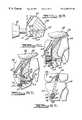
- FIG. 1is a side view of an apparatus for tibial fixation of a soft tissue graft according to the teachings of the present invention
- FIG. 2is a top view of the tibial fixation apparatus of FIG. 1;
- FIG. 3is a side cross-sectional view of the tibial fixation apparatus of FIG. 1 taken along line 3 — 3 of FIG. 2;
- FIG. 4is a top view of a counterbore drill guide used in preparing a counterbore to nestingly receive the tibial fixation apparatus of FIG. 1;
- FIGS. 5A-5Eillustrates a method for attaching a soft tissue graft using the tibial fixation apparatus according to the teachings of the present invention
- FIGS. 6A-6Eillustrates another method for attaching a soft tissue graft using the tibial fixation apparatus according to the teachings of the present invention
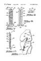
- FIG. 7is a top view of another apparatus for tibial fixation of a soft tissue graft according to the teachings of the present invention.
- FIG. 8is a bottom view of the tibial fixation apparatus of FIG. 7;
- FIG. 9is a front view of the tibial fixation apparatus of FIG. 7;
- FIG. 10is a side cross-sectional view of the tibial fixation apparatus of FIG. 7 taken along line 10 — 10 of FIG. 7;
- FIG. 11is a perspective view illustrating a method for positioning the tibial fixation apparatus of FIG. 7;
- FIG. 12is a side cross-sectional view taken along line 12 — 12 of FIG. 11 illustrating the method for positioning the tibial fixation apparatus of FIG. 7;
- FIG. 13is a top-end view of another apparatus for tibial fixation of a soft tissue graft according to the teachings of the present invention.
- FIG. 14is a bottom-end view of a tibial fixation apparatus of FIG. 13;
- FIG. 15is a side-end view of the tibial fixation apparatus of FIG. 13;
- FIG. 16is a top view of an instrument utilized for grasping the tibial fixation apparatus of FIG. 13;
- FIG. 17is a side cross-sectional view illustrating a method for positioning the tibial fixation apparatus of FIG. 13 employing the instrument of FIG. 16;
- FIG. 18is a side cross-sectional view of a tibial fixation apparatus according to the teachings of the preferred embodiment of the present invention.
- FIG. 19is a perspective view of a counterbore guide used in preparing a counterbore to nestingly receive the tibial fixation apparatus of FIG. 18;
- FIG. 20is an elevational view of a first portion of a multi-purpose instrument
- FIG. 21is an elevational view of a second portion of the multi-purpose instrument of FIG. 20;
- FIGS. 22A-22Dillustrates a first preferred method for attaching a soft tissue graft using the tibial fixation apparatus according to the teachings of the preferred embodiment of the present invention
- FIG. 23is a perspective view of another counterbore guide used in preparing a counterbore to nestingly receive the tibial fixation apparatus of FIG. 18;
- FIG. 24is an elevational view of another multi-purpose instrument.
- FIGS. 25A-25Dillustrates a second preferred method for attaching a soft tissue graft using the tibial fixation apparatus according to the teachings of the preferred embodiment of the present invention.
- the apparatus 10includes a cylindrical body 12 having a diameter of about 16 millimeters and a plurality of spikes 14 .
- the cylindrical body 12includes a substantially cylindrical sidewall 16 having beveled or rounded edges 18 and a substantially flat planar relief face 20 formed into a portion of the cylindrical sidewall 16 .
- the body 12further defines a concentric internal bore 22 having an internal sidewall 24 with a diameter of about 0.234 inches which is adapted to receive a compression bone screw, further discussed herein.
- a first side or top 26 of the body 12includes a concentric counterbore 28 operable to flushly receive a head of the compression screw.
- a second side or bottom 30 of the body 12is substantially planar and has the plurality of spikes 14 extending out from the second side 30 .
- the plurality of spikes 14includes a first plurality or four cylindrical guide spikes 32 each having a length from the top 26 of the body 12 to the tip 34 of the spikes 32 of about 0.52 inches and a cylindrical diameter of about 0.062 inches.
- the four spikes 32are positioned concentrically about the body 12 at a radius of about 0.25 inches from the center of the body 12 .
- the plurality of spikes 14further includes a second plurality or thirteen cylindrical engagement spikes 36 each having a length from the top 26 of the body 12 to the tip 34 of the spikes 36 of about 0.34 inches and a cylindrical diameter of about 0.047 inches.
- the cylindrical spikes 32 and 36each include the pointed end 34 operable to engage and penetrate cancellous and cortical bone.
- the engagement spikes 36are positioned between the guide spikes 32 and the internal bore 22 in such a manner that the engagement spikes 36 are able to penetrate and secure the soft tissue graft at multiple sites, further discussed herein.
- the apparatus or washer 10is preferably made from a suitable biocompatible material such as titanium, stainless steel, titanium alloy, cobalt-chrome-molybdenum alloy, polymer, resorbable polymer, etc.
- the apparatus 10preferably consists of an assembly of separate spikes 14 which are welded to the body 12 , via welds 38 .
- the apparatus 10may be cast or machined to the required shape and size.
- a counterbore drill guide 40is shown for use in preparation of a substantially perpendicular counterbore relative to a tibial tunnel formed in a tibia, further discussed herein.
- the counterbore drill guide 40includes a substantially cylindrical body 42 defining a planar notched region 44 having a center aperture 46 for receipt of a counterbore drill bit.
- a positioning bar 48Positioned adjacent to the notched region 44 is a positioning bar 48 passing medially through the body 42 .
- the positioning bar 48is slidably engaged with the body 42 and is utilized to engage the medial cortex of the tibia to provide a predetermined insertion length of the counterbore drill guide 40 into the tibial tunnel.
- the body 42 of the counterbore drill guide 40is about 7 millimeters in diameter, with the notched region 44 beginning at about 20 millimeters from a distal end of the drill guide 40 .
- the notched region 44is about 17 millimeters wide having about a 3.5 millimeter diameter centering hole 46 .
- the positioning bar 48is set back about 10 millimeters from the center of the centering hole 46 , thereby providing a predetermined insertion length within the tibial tunnel of about 38.5 millimeters.
- the counterbore drill guide 40is preferably made from stainless steel or other suitable material.
- soft tissue graftsare harvested for use in an intrarticular cruciate ligament (ACL) reconstruction.
- ACLintrarticular cruciate ligament
- the semitendinosus and gracilis tendons from their respective hamstring musclesare generally used and harvested from the patient or by way of donor tendons using techniques well known in the art.
- synthetic graftsmay also be employed.
- the harvested graftswill generally consist of two tubular grafts which are subsequently looped at their mid-section to form a four bundle graft.
- the four bundle graftshould be sized to pass without friction through a tibial and femoral tunnel.
- a tibial tunnel or bore 52is drilled through the tibia 54 and into the femur 56 creating a femoral tunnel 58 .
- the tibial tunnel 52will typically have a diameter between about 7 to 13 millimeters, preferably 8-9 millimeters, and is bored utilizing a drill bit and a driver.
- the tibial tunnel 52exits at about the center of the tibial plateau and enters the tibia 54 at about 50 millimeters from the top of the tibial plateau medial to the tibial tubercle or at the medial cortex.
- the drill bit utilized to bore the tibial tunnel 52also generally bores the femoral tunnel 58 in the femur 56 by continuing to extend the drill bit through the tibial tunnel 52 and into the femur 56 .
- the tibial tunnel 52 and the femoral tunnel 58are bored using techniques well known in the art which may include the use of alignment or drill guide mechanisms in combination with a drill bit and driver.
- the body 42 of the counterbore drill guide 40is axially slid into the entrance opening 60 of the tibial tunnel 52 .
- the counterbore drill guide 40is advanced into the tibial tunnel 52 until the positioning bar 48 is flush against the medial cortex of the tibia 54 . This will align the centering hole 46 adjacent to an anterior edge 64 of the entrance opening 60 of the tibial tunnel 52 .
- a counterbore 66is formed substantially perpendicular to the tibial tunnel 52 using a counterbore bit 68 and a drive mechanism 70 .
- the counterbore bit 68includes a centering nose 72 which rotatably engages the centering hole 46 formed into the counterbore drill guide 40 .
- the centering nose 72is formed similar to a drill bit so that the centering nose 72 drills into the tibia 54 .
- the counterbore 66is preferably bored to remove the anterior edge 64 of the entrance opening 60 providing a substantially perpendicular counterbore 66 .
- the centering nose 72is directed through the tibia 54 and inserted in the centering hole 46 in the counterbore drill guide 40 such that the counterbore bit 68 is perpendicular to a posterior wall 74 of the tibial tunnel 52 .
- the counterbore bit 68is advanced to remove the anterior tibial cortex adjacent to an anterior wall 76 until it seats in the notch region 44 in the counterbore drill guide 40 .
- the bone reamingsmay then be collected and saved for subsequent grafting of the tibial tunnel 52 .
- a four bundle graft 78is first secured within the femoral tunnel 58 of the femur 56 using one of many techniques known in the art.
- the four bundle graft 78is secured within the femoral tunnel 58 of the femur 56 by means of a bone mulch screw, set forth in U.S. Pat. No. 5,674,224, “BONE MULCH SCREW ASSEMBLY FOR ENDOSTEAL FIXATION OF SOFT TISSUE GRAFTS AND METHOD FOR USING SAME”, which is hereby incorporated by reference.
- the graft 78With the graft 78 secured within the femoral tunnel 58 , the graft 78 extends out through the tibial tunnel 52 .
- the apparatus 10is then engaged and secured to the tibia 54 by use of an impactor 80 in combination with a mallet.
- the impactor 80has a generally cylindrical body 82 which tapers to a striking end 84 .
- the impactor 80includes a complimentary face 86 having a concentric guide post 88 which is received within the internal bore 22 and an arcuate surface 90 which is received within the counterbore 28 .
- the impactor 80further includes an edge guide 92 which engages and mates with the planar relief face 20 formed within the apparatus 10 .
- the edge guide 92enables the surgeon to properly rotatably align the apparatus 10 by simply rotating the impactor 80 within the counterbore 66 and engaging the planer face 20 with the edge guide 92 .
- the graft 78is oriented such that two grafts 94 and 96 of the four bundle graft 78 pass along a first side of the guide post 88 and two grafts 98 and 100 pass along a second side the guide post 88 such that each pair of grafts are positioned or guided between the guide post 88 and the longer guide spikes 32 .
- the apparatus 10is initially partially engaged with only the guide spikes 32 penetrating cancellous and cortical bone of the tibia 54 and the relief face 20 directed toward the entrance opening 60 .
- the four bundle graft 78is appropriately tensioned by pulling the four bundle graft 78 under the engagement spikes 36 within the counterbore 66 and out of an area 102 defined by the relief 20 and the counterbore 66 without binding on the sidewall 16 or the counterbore 66 .
- the two stage spikes 14 having the first plurality of spikes 32 of a first length and the second plurality of spikes 36 having a second shorter lengthenables the apparatus 10 to be initially secured to the tibia 54 with only the spikes 32 , while allowing proper tensioning and guiding of the four bundle graft 78 .
- the four bundle graft 78is properly tensioned generally by means of pulling on the ends of the graft 78 extending out of the area 102 under the relief 20 manually or with a tensioning device with the knee in full extension.
- a preferred tensioning deviceis set forth in U.S. Pat. No. 5,507,750 entitled, “METHOD AND APPARATUS FOR TENSIONING GRAFTS AND LIGAMENTS”, which is hereby incorporated by reference.
- the engagement spikes 36penetrate the two grafts 94 and 96 on the first side of the guide post 88 at multiple sites and the two grafts 98 and 100 on the second side of the guide post 88 to maintain proper tensioning of the four bundle graft 78 .
- the apparatus or washer 10thus seats or nests flush within the counterbore 66 thereby eliminating any objects extending out beyond the tibia 54 .
- the relief 20is also used to eliminate any portion of the apparatus 10 from extending out beyond the tibia 54 .
- a drill guide 101is inserted into the internal bore 22 of the apparatus 10 to maintain the separation of the four bundle graft 78 .
- the drill guide 101is advanced between the two grafts 94 and 96 on the first side of the guide post 88 and the two grafts 98 and 100 on the second side of the guide post 88 so that it is flush against the posterior wall 74 of the tibial tunnel 52 .
- a 3.5 millimeter drill bit 104 attached to the driver 70is then utilized to drill a bore 106 through the tibia 54 to the posterior cortex of the tibia 54 . Once the bore 106 is drilled through the tibia 54 , the depth of the bore 106 is measured and the posterior cortex region is tapped using an appropriate tap.
- a low profile compression screw 108is inserted into the internal bore 22 and screwed into the bore 106 in the tibia 54 to threadably secure the compression screw 108 within the bore 106 and complete the fixation of the apparatus 10 within the counterbore 66 .
- the compression screw 108includes a head 110 which is flushly received within the counterbore 28 , a threaded section 112 , and a cylindrical non-threaded section 114 passing through the body 12 of the apparatus 10 . Once the compression screw 108 has been fully secured, the ends of the grafts 94-100 may be trimmed back within the area 102 .
- the apparatus 10provides a substantially stiff and slippage free anchoring for the graft 78 .
- FIGS. 6A-6Eanother method for tibial fixation of a soft tissue graft will now be described.
- like reference numeralswill be used to reference to like structures.
- tunnel or hole placementis again performed.
- the tibial tunnel or bore 52is drilled through the tibia 54 and into the femur 56 creating a femoral tunnel 58 .
- the tibial tunnel 52will typically have a diameter between about 7 to 13 millimeters, preferably 8-9 millimeters, and is bored utilizing a drill bit and a driver.
- the tibial tunnel 52exits at about the center of the tibial plateau and enters the tibia 54 at about 50 millimeters from the top of the tibial plateau medial to the tibial tubercle or at the medial cortex. Since the tibial tunnel 52 angles through the tibia 54 , it creates an elliptical entrance opening 60 and an elliptical exit opening 62 .
- the drill bit utilized to bore the tibial tunnel 52also generally bores the femoral tunnel 58 in the femur 56 by continuing to extend the drill bit through the tibial tunnel 52 and into the femur 56 .
- the tibial tunnel 52 and the femoral tunnel 58are bored using techniques well known in the art which may include the use of alignment or drill guide mechanisms in combination with a drill bit and driver.
- a pilot hole 55is bored straight through the tibia 54 parallel with the tibia plateau. Specifically, the pilot hole 55 is started at the intersection point at the bottom of the entrance 60 and is drilled from the anterior medial to posterior lateral side utilizing a drill bit 57 driven by the drive mechanism 70 .
- the pilot hole 55is preferably about 2 to 3 millimeters in diameter.
- a counterbore 59is formed at the anterior medial side of the tibia 54 using a counterbore bit 61 and the drive mechanism 70 .
- the counterbore bit 61includes a pilot nose 63 which engages the pilot hole 55 to accurately align the counterbore bit 61 concentric with the pilot hole 55 and relative to the entrance opening 60 .
- the counterbore 59is preferably bored to a depth of about 6 to 7 millimeters which intersects with the tibial tunnel 52 or entrance opening 60 .
- the four bundle graft 78is first secured within the femoral tunnel 58 of the femur 56 using one of the many techniques known in the art.
- the four bundle graft 78is preferably secured within the femoral tunnel 58 of the femur 56 by means of the bone mulch screw, set forth in U.S. Pat. No. 5,674,224 “BONE MULCH SCREW ASSEMBLY FOR ENDOSTEAL FIXATION OF SOFT TISSUE GRAFTS AND METHOD FOR USING SAME”, which is hereby incorporated by reference.
- the graft 78With the graft 78 secured within the femoral tunnel 58 , the graft 78 extends out through the tibial tunnel 52 .
- the apparatus 10is then engaged to the tibia 54 by means of a bone screw 65 having a head 67 and the spikes 32 .
- the graft 78is oriented such that the two grafts 94 and 96 of the four bundle graft 78 pass along a first side of the bone screw 65 and two grafts 98 and 100 pass along a second side the bone screw 65 such that the pair of grafts are positioned or guided between the bone screw 65 and the longer guide spikes 32 .
- the apparatus 10is initially partially engaged with only the guide spikes 32 penetrating cancellous and cortical bone of the tibia 54 and the bone screw 65 partially set.
- the four bundle graft 78is appropriately tensioned by pulling the four bundle graft 78 under the engagement spikes 32 along the counterbore 59 and out of an area 69 defined by the relief 20 and the counterbore 59 without binding on the sidewall 16 or the counterbore 59 .
- the two stage spikes 14 having the first plurality of spikes 32 of a first length and the second plurality of spikes 36 having a second shorter lengthenables the apparatus 10 to be initially secured to the tibia 54 with only the spike 32 and bone screw 65 , while allowing tensioning and guiding of the four bundle graft 78 .
- the bone screw 65is further turned to fully seat the apparatus or washer 10 flush within the counterbore 59 , as shown clearly in FIG. 6 D.
- the engagement spikes 36penetrate the two grafts 94 and 96 on the first side of the bone screw 65 and the two grafts 98 and 100 on the second side of the bone screw 65 to maintain proper tensioning of the four bundle graft 78 .
- the apparatus or washer 10thus seats flush within the counterbore 59 , thereby eliminating any objects extending out beyond the tibia 54 .
- the ends of the grafts 94-100may be trimmed back within the area 64 .
- FIGS. 7-10an apparatus or wedge 116 for tibial fixation of a soft tissue graft according to the teachings of another embodiment of the present invention is shown.
- the wedge 116is preferably made from a suitable biocompatible material such as titanium, stainless steel, titanium alloy, cobalt-chromemolybdenum alloy, polymer, resorbable polymer, etc.
- the wedge 116includes a first side 118 and a second side 120 .
- the first sideincludes a plurality of parallel running teeth 122 each defined by a first vertical sidewall 124 and a second angled sidewall 126 .
- Each tooth 122includes three axial or perpendicular notches 128 formed into the tooth 122 and an edge 130 .
- the notches 128being perpendicular to the teeth 122 provides additional surface area, as well as two opposed planes in which to grab or engage the four bundle graft 78 .
- the edge 130 of each tooth 122has a slight arcuate shape, as shown clearly in FIG. 9 .
- the second side 120 of the wedge 116includes an arcuate shaped periphery 132 with a threaded face 134 formed therein.
- the threaded face 134is operable to be threadably engaged by an interference screw, further discussed herein.
- the wedge 116further includes a first or distal end 136 and a second or proximal end 138 .
- the distal end 136includes a rounded nose 140 having the three notches 128 on the first side 118 and a V-shaped notch or groove 142 on the second side 120 .
- the proximal end 138includes a pair of wings 144 defining an open region 146 which provides for clearance of the interference screw.
- the wings 144are angled and sized such that when the wedge 116 is axially inserted into the tibial tunnel 52 , a face 148 of the wings 144 lies substantially flush or along the same plane as the tibia 54 .
- the size of the wings 144are also larger than the diameter of the tibial tunnel 52 such that the wings 144 prevent the wedge 116 from being axially inserted or drawn into the tibial tunnel 52 more than a predetermined amount.
- FIG. 10a side cross-sectional view of the wedge 116 is shown having a wider or thicker distal end 136 and a thinner or narrower proximal end 138 .
- the threaded face 134is also clearly shown having individual threads 150 formed within the arcuate periphery 132 .
- the orientation of the thinner proximal end 138 which gets thicker moving out to the distal end 136compensates or is complimentary to the shape of the interference screw utilized. This sizing also provides engagement adjustment by locating the interference screw either further in along the threaded face 134 near the distal end 136 or conversely locating the interference screw back towards the proximal end 138 , further discussed herein.
- the soft tissue graftsare initially harvested and prepared for use in the articular cruciate ligament (ACL) reconstruction.
- ACLarticular cruciate ligament
- the tibial tunnel 52is bored through the tibia 54 and into the femur 56 creating the femoral tunnel 58 .
- the four bundle graft 78is then secured within the femoral tunnel 58 using the bone mulch screw described above. Once the four bundle graft 78 has been secured within the femoral tunnel 58 , the four bundle graft 78 is passed through the tibial tunnel 52 .
- the four bundle graft 78With the four bundle graft 78 extending out of the tibial tunnel 52 , the four bundle graft 78 is properly tensioned by pulling on the proximal end of the four bundle graft 78 . With the four bundle graft 78 properly tensioned, the wedge 116 is positioned axially in the tibial tunnel 52 below the four bundle graft 78 .
- the first side 118 having the plurality of teeth 122are oriented axially and adjacent to the four bundle graft 78 to substantially engage and hold the four bundle graft 78 under proper tensioning against the upper or anterior side 76 of the tunnel 52 .
- An interference screw 152 having threads 154 which matingly receive threaded face 134is axially inserted within the tibial tunnel 52 .
- An optional guide wire 156may be utilized which passes through a bore 158 . The guide wire 156 passes from the entrance opening 60 out the exit opening 62 and is used for positioning and aligning the interference screw 152 during axial insertion of the interference screw 152 .
- a driversuch as a hex driver engages the head 162 of the interference screw 152 to axially drive the interference screw 152 between the second side 120 and the sidewall 74 .
- the threads 154 of the interference screw 152engage the threads 150 of the threaded face 134 , as well as the sidewall 74 , thereby causing the interference screw 152 to axially advance from the proximal end of the tunnel 52 to the distal end of the tunnel 52 .
- the wings 144prevent the wedge 116 from being axially drawn into the tibial tunnel 52 by more than a predetermined amount, as well as maintains the pre-set tension on the four bundle graft 78 .
- the teeth 122further engage and compress the four bundle graft 78 under the wedge compression of the interference screw 152 .
- the side cross-section wedge shape of the wedge 116is complimentary to the shape of the interference screw 152 , such that initial engagement of the interference screw 152 with the wedge 116 provides a substantially planer uniform force which is substantially transverse or perpendicular to the tibial tunnel 52 .
- the wedge 116Upon further driving the interference screw 152 within the tunnel 52 , the wedge 116 will provide additional or increased compression in the distal end 136 as the interference screw 152 passes into the notched region 142 .
- the plurality of teeth 122 having the perpendicular notches 128provide a substantial surface engagement area to securely axially retain the four bundle graft 78 under proper tensioning endoscopically.
- the enlarged surface areadistributes the tensioning force more uniformly over the graft 78 . Still further, by providing a substantially non-moving engagement member against the graft 78 , this reduces the possibility that the graft 78 may be frayed, slip or cut.
- a proximal end 164 of a wedge 166according to the teachings of another embodiment of the present invention is shown.
- like reference numeralswill be used to refer to similar structures.
- the distal end of the wedge 166is the same as the distal end 136 of wedge 116 and the only modification here is to the proximal end 164 .
- the proximal end 164does not include a pair of wings 144 but includes or defines a pair of notched regions 168 which are operable to be engaged by an endotibial plate grasper 172 , shown in FIG. 16, and further discussed herein.
- the notches or grasper slots 168are V-shaped and defined by a bevelled or rounded end 170 of the wedge 166 .
- the endotibial plate grasper 172includes complementary tines or tips 174 which engage the notches 168 to firmly grasp and secure the plate 176 .
- Set back from the tips 174 and adjacent theretois an alignment plate 176 sized to be larger than the tibial tunnel 52 and angled substantially similar to the wings 144 .
- the plate grasper or instrument 172further includes a handle 178 having a locking mechanism 180 such that the plate 166 can be engaged by the tips 174 and locked or held secured by the locking mechanism 180 .
- the soft tissue graftsare harvested and prepared using known techniques.
- the tibial tunnel 52 and the femoral tunnel 58are bored through both the tibia 54 and the femur 56 .
- the four bundle graft 78is again secured within the femoral tunnel 58 using known techniques such as the bone mulch screw identified above.
- the four bundle graft 78 extending through the tibial tunnel 52is then properly tensioned.
- the instrument 172engages the notches 168 of the wedge 166 , via the tips 174 .
- the wedge 166With the wedge 166 being firmly held by the instrument 172 , via the locking mechanism 180 , the wedge 166 is axially inserted into the tibial tunnel 52 until the plates 176 engage the entrance opening 60 of the tibial tunnel 52 .
- the teeth 122transversely engage the four bundle graft 78 , as the interference screw 152 is axially driven into the tibial tunnel 52 .
- the plate 176prohibits the wedge 166 from being axially drawn into the tibial tunnel 52 by more than a predetermined amount thereby maintaining proper graft tensioning, as well as maintaining the proper alignment of the wedge 166 against the four bundle graft 78 .
- the plate grasper 172is removed from the wedge 166 , thereby providing a properly tensioned and endoscopically axially secured four bundle graft 78 .
- FIG. 18an apparatus 200 for tibial fixation of a soft tissue graft according to the teachings of a first preferred embodiment of the present invention is shown.
- the apparatus or washer 200is substantially similar to the apparatus 10 , as shown in FIGS. 1-3, and in this regard, like reference numerals will be used to identify like structures.
- the fixation apparatus or washer 200includes the cylindrical body 12 and the plurality of spikes 14 .
- the cylindrical body 12includes the cylindrical sidewall 16 having the bevelled or rounded edges 18 and the substantially flat planar relief face 20 formed into a portion of the cylindrical sidewall 16 .
- the body 12further includes the internal bore 22 which includes a threaded internal sidewall 202 which is able to be threadably secured to a combination implant and guide instrument, further discussed herein.
- the top 26 of the bodyalso includes the concentric counterbore 28 and the bottom 30 of the body 12 includes the plurality of spikes 14 extending out from the second side 30 .
- the washer 200may be made from any suitable bio-compatible material and may also be made in various different sizes, as with the washer 10 , depending on the patient's needs and the doctor's requirements.
- a counterbore guide 204is shown for use in preparing of a substantially perpendicular counterbore relative to a tibial tunnel formed in a tibia, further discussed herein.
- the counterbore guide 204includes a substantially cylindrical body 206 having a circular handle 208 with a planar region 210 .
- Extending substantially perpendicular from the cylindrical body 206is a positioning bar 212 which is secured to the cylindrical body 206 by way of a groove formed in the lower portion of the cylindrical body 206 and a weld.
- the positioning bar 212is utilized to engage the medial cortex of the tibia at two points to provide a predetermined insertion length of the counterbore guide 204 into the tibial tunnel.
- the guide bushing 214includes a cylindrical bore 216 which mates and is concentric with a bore 218 defined by the cylindrical body 206 .
- the guide bushing 214is secured substantially perpendicular to the cylindrical body 206 by means of a weld or any other appropriate fixation.
- the guide bushing 214engages the opening of the tibial tunnel and is operable to permit a guide bore to be formed substantially perpendicular to the tibial tunnel, further discussed herein.
- a combination implant and guide instrument 220which is operable to implant the washer 200 , as well as perform other purposes, is shown in FIGS. 20 and 21.
- the instrument 220includes a first awl portion 222 and a second guide portion 224 .
- the first awl portion 222includes a cylindrically shaped handle 226 having notched regions 228 and an elongated neck 230 . Extending substantially concentric with the handle 226 is an elongated cylindrical awl or guide shaft 232 having a distal point or tip 234 .
- the first portion 222also includes a threaded connector member 236 which is operable to threadably engage the second portion 224 , further discussed herein.
- the second guide portion 224also includes a substantially cylindrical handle 238 having notches 240 and an elongated neck 242 . Extending from the substantially cylindrical neck 242 is a circular impact plate 244 .
- the impact plate 244may either be formed integrally with the guide member 224 or may be formed as a separate annular member having an internal threaded bore which is threadably received upon a threaded connection member 246 .
- the threaded connection member 246extends out beyond the impact plate 244 and is operable to threadably engage threaded sidewall 202 of the fixation apparatus 200 , further discussed herein. Passing concentrically through the drill guide 224 is a centerbore 248 having an internal threaded sidewall portion 250 .
- the bore 248is operable to receive the guide shaft 232 , while the threaded sidewall 250 threadably engages the threaded connection member 236 .
- the first portion 222 and the second portion 224form the combination implant and guide instrument 220 which is operable to perform several functions during the implantation procedure.
- FIGS. 22A-22Da first preferred method for tibial fixation of a soft tissue graft will now be described.
- soft tissue graftsare harvested and prepared using known techniques and as previously described.
- tunnel or hole placementis performed, as also previously described.
- the tibial tunnel or bore 52is drilled through the tibia 54 and into the femur 56 creating the femoral tunnel 58 .
- the cylindrical body 206 of the counterbore guide 204is axially slid into the entrance opening 60 of the tibial tunnel 52 .
- the counterbore guide 204is slidably advanced into the tibial tunnel 52 until the positioning bar 212 engages and is flush against the medial cortex of the tibial 54 along two contact points. This will align the guide bushing 214 substantially adjacent and in contact with the anterior edge 64 or superior portion of the entrance opening 60 of the tibial tunnel 52 . This provides for a stable three point contact at the entrance opening 60 to the tibial tunnel 52 .
- the planar region 210 of the handle 208acts as a site mechanism with the guide bushing 214 to insure proper rotation of the counterbore guide 204 in the tibial tunnel 52 .
- the substantially three point contactshould be made within the oval opening 60 by way of the positioning bar 212 and the guide bushing 214 .
- the first portion 222 of the combination implant and guide instrument 220is employed.
- the awl or guide shaft 232is slidably received within the bore 216 of the guide bushing 214 until the point 234 engages the posterior wall 74 of the tibial tunnel 52 .
- the first portion 222is impacted by striking the handle 226 with a mallet or other appropriate impact device.
- the shaft 232is impacted until the tip 234 is substantially adjacent to the posterior side of the tibia 54 .
- the guide shaft 232is removed from the guide bushing 214 and the counterbore guide 204 is slidably removed from the tibial tunnel 52 . This provides a substantially perpendicular guide bore 254 relative to the tibial tunnel 52 .
- the counterbore 66is formed substantially perpendicular to the tibial tunnel 52 using a counterbore bit 256 and the drive mechanism 70 , as shown in FIG. 22 B.
- the counterbore bit 256includes a substantially cylindrical centering nose 258 which rotatably engages the guide bore 254 .
- the counterbore 66is preferably bored to remove the anterior edge 64 or the superior portion of the entrance opening 60 to provide a substantially perpendicular counterbore 66 .
- the counterbore bit 256is perpendicular to the posterior wall 74 of the tibial tunnel 52 and is advanced to the posterior wall 74 .
- the four bundle graft 78is first secured within the femoral tunnel 58 of the femur 56 using one of the many techniques known in the art and as previously described herein. Once the graft 78 is secured within the femoral tunnel 58 , the graft 78 extends out through the tibial tunnel 52 . The second portion 224 of the combination implant and guide instrument 220 is then threadably secured to the first portion 222 by way of the threaded sidewall 250 and the threaded connection member 236 . Once assembled, the shaft 232 extends out beyond the impact plate 244 by about 1.25 inches.
- the threaded connection member 246is then threadably engaged with the threaded sidewall 202 of the apparatus 200 to removably secure the apparatus 200 to the impact plate 244 .
- the impact plate 244seats within the spherical counterbore 28 and the shaft 232 extends out the center of the fixation apparatus 200 .
- the shaft 232also extends out beyond the spikes 32 to permit guiding of the apparatus 200 substantially perpendicular to the tibial tunnel 52 .
- the planar relief face 20 of the apparatus 200is first positioned inferior to the counterbore 66 .
- the shaft 232is then slidably engaged within the guide bore 254 until the spikes 32 engage the posterior portion 74 of the tibial tunnel 52 .
- the graft 78is oriented, as shown in FIG.
- the fixation apparatus 200is initially engaged with only the guide spikes 32 penetrating cancellous bone of the tibia 54 with the relief face 20 directed toward the entrance opening 60 .
- the four bundle graft 78is appropriately tensioned by pulling the four bundle graft 78 under the engagement spikes 36 within the counterbore 66 and out the area 102 defined by the relief 20 (see FIG. 5E) without binding on the sidewall 16 or the counterbore 66 .
- the apparatus 200is fully implanted or nested within the counterbore 66 by striking the handle 226 with a mallet or other appropriate driving device, as shown clearly in FIG. 22 C.
- the engagement spikes 36penetrate the two grafts 94 and 96 on the first side of the guide shaft 232 at multiple sights and the two grafts 98 and 100 on the second side of the guide shaft 232 to maintain the proper tensioning of the four bundle graft 78 .
- the first portion 222 of the combination implant and guide instrument 220is threadably disengaged from the second portion 224 .
- thisprovides a guide substantially perpendicular to the tibial tunnel 52 , via the bore 248 , passing through the second portion 224 .
- a drill bit 260 driven by the driver 70is then guided through the bore 248 , between the grafts 94 and 96 and 98 and 100 and down through the guide bore 254 , shown in FIG. 22 D.
- the drill bit 260enlarges the guide bore 254 for receipt of the low profile compression screw 108 , shown in FIG. 5 D.
- the bore 262may then be tapped with an appropriate tap, should this be desired.
- the length of the screw 108is then determined using any conventional measuring instrument. Once selected, the low profile compression screw 108 is passed through the apparatus 200 and threaded into the bore 262 to complete the fixation of the apparatus 200 .
- the counterbore guide 204 ′is substantially the same as the counterbore guide 204 , except that the counterbore guide 204 ′ includes or defines a slot 264 passing through the cylindrical body 206 and a slot 266 passing through the guide bushing 214 .
- Each slot 264 and 266enables a guide wire, further discussed herein, to be slidably passed through each slot and out from the counterbore guide 204 ′.
- FIG. 24A second combination implant and guide instrument 270 according to the teachings of a second preferred embodiment of the present invention is shown in FIG. 24, which may be used in place of the instrument 220 .
- the instrument 270includes a substantially cylindrical handle 272 having notches 274 and an elongated tubular shaft 276 .
- the shaft 276defines a substantially cylindrical bore 278 passing axially through the shaft 276 .
- the bore 278includes a threaded sidewall portion 280 which is operable to be threadably engaged by a threaded connector member 282 extending from the handle 272 .
- a circular impact head or plate 284Positioned at the end of the shaft 276 opposite the handle 272 is a circular impact head or plate 284 having a substantially spherical impact face 286 and a threaded connection member 288 .
- the implant plate 284may be a separate member threaded on the connection member 288 or integral with the shaft 276 .
- the connection member 288threadably engages the threaded sidewall 202 of the apparatus 200 , while the spherical face 286 nestingly rests within the counterbore 28 .
- FIGS. 25A-25CA second preferred method for tibial fixation of a soft tissue graft which employs the counterbore guide 204 ′ and the combination implant and guide instrument 270 is shown in FIGS. 25A-25C.
- the tibial tunnel 52is again drilled through the tibia 54 and into the femur 56 to form the femoral tunnel 58 .
- the counterbore guide 204 ′is axially slid into the entrance opening 60 of the tibial tunnel 52 with the positioning bar 212 and the guide bushing 214 coming to rest against the opening 60 .
- a conventional guide wire 290is passed through the guide bushing 214 and fixedly driven into the tibia 54 , via the driver 70 to create a guide box that secures the guide wire 290 .
- the counterbore guide 204 ′is slidably removed from the tibial tunnel 52 as the guide wire 290 remains in place substantially perpendicular to the tibial tunnel 52 .
- the guide wire 290exits through the slots 266 and 264 , respectively.
- the counterbore 66is again formed by the use of a counterbore bit 292 which is driven by the driver 70 .
- the counterbore bit 292includes an elongated shaft 294 and includes and defines a cylindrical bore 296 passing through the entire counterbore bit 292 .
- the counterbore bit 292is slidably inserted over the guide wire 290 and rotatably advanced to form the counterbore 66 , shown clearly in 25 B, as the guide wire 290 passes up through the counterbore bit 292 .
- the combination implant and guide instrument 270threadably receives the apparatus 200 , via the threaded sidewall 202 and the threaded connector member 288 .
- the impact face 284nestingly seats within the counterbore 28 as the apparatus 200 threadably engages the threaded connector member 288 .
- the apparatus 200is again aligned substantially perpendicular to the tibial tunnel 52 by means of the guide wire 290 .
- the guide wire 290extends through the apparatus 200 and into the bore 278 of the instrument 270 so that the instrument 270 is slidably guided by the guide wire 290 substantially perpendicular to the tibial tunnel 52 .
- the spikes 32are first set in the posterior wall 74 of the tibial tunnel 52 with the planar face 20 facing inferiorly.
- the graft 78is again tensioned as previously described and the apparatus 200 is then fully seated by impacting the handle 272 with a mallet or other appropriate device.
- the handle 274is threadably removed from the shaft 276 , via the threaded connector member 282 , thereby exposing the bore 278 .
- the bore 278guides the drill bit 260 driven by the driver 70 , as shown similarly in FIG. 22D to form the enlarged bore 262 .
- the low profile compression screw 108is then inserted into the bore 262 to complete the fixation of the apparatus 200 within the counterbore 66 .
- the combination implant and guide instrument 220performs at least three functions consisting of forming the guide bore 254 , implanting the fixation apparatus 200 and guiding the drill bit 260 .
- the combination implant and guide instrument 270performs at least two functions including implanting the fixation apparatus 200 and guiding the drill bit 260 . Accordingly, use of the combination implant and guide instrument 220 or 270 reduces the amount of separate instrumentation required to secure the soft tissue graft 78 , as well as reduces or eliminates additional steps in the technique. Additionally, by maintaining one portion of each instrument 220 or 270 secured to the fixation apparatus 200 during the implant procedure, further accuracy is achieved.
Landscapes
- Health & Medical Sciences (AREA)
- Life Sciences & Earth Sciences (AREA)
- Orthopedic Medicine & Surgery (AREA)
- Surgery (AREA)
- Veterinary Medicine (AREA)
- Engineering & Computer Science (AREA)
- Biomedical Technology (AREA)
- Heart & Thoracic Surgery (AREA)
- Public Health (AREA)
- Rheumatology (AREA)
- Animal Behavior & Ethology (AREA)
- General Health & Medical Sciences (AREA)
- Oral & Maxillofacial Surgery (AREA)
- Molecular Biology (AREA)
- Medical Informatics (AREA)
- Nuclear Medicine, Radiotherapy & Molecular Imaging (AREA)
- Rehabilitation Therapy (AREA)
- Cardiology (AREA)
- Transplantation (AREA)
- Vascular Medicine (AREA)
- Dentistry (AREA)
- Surgical Instruments (AREA)
- Prostheses (AREA)
Abstract
Description
Claims (18)
Priority Applications (11)
| Application Number | Priority Date | Filing Date | Title |
|---|---|---|---|
| US09/356,959US6280472B1 (en) | 1997-07-23 | 1999-07-19 | Apparatus and method for tibial fixation of soft tissue |
| US09/616,544US6482232B1 (en) | 1997-07-23 | 2000-07-14 | Apparatus and method for tibial fixation of soft tissue |
| AT00306127TATE343353T1 (en) | 1999-07-19 | 2000-07-19 | DEVICE FOR ATTACHING SOFT TISSUE TO THE TIBIA |
| DE2000631482DE60031482T2 (en) | 1999-07-19 | 2000-07-19 | Device for attaching soft tissue to the tibia |
| EP20000306127EP1070482B1 (en) | 1999-07-19 | 2000-07-19 | Apparatus for tibial fixation of soft tissue |
| US10/167,074US6755840B2 (en) | 1997-07-23 | 2002-06-10 | Apparatus and method for tibial fixation of soft tissue |
| US10/874,915US7211111B2 (en) | 1997-07-23 | 2004-06-23 | Apparatus and method for tibial fixation of soft tissue |
| US11/742,009US8221498B2 (en) | 1997-07-23 | 2007-04-30 | Apparatus and method for tibial fixation of soft tissue |
| US13/242,143US9011534B2 (en) | 1997-07-23 | 2011-09-23 | Apparatus and method for tibial fixation of soft tissue |
| US13/549,912US8647385B2 (en) | 1997-07-23 | 2012-07-16 | Apparatus and method for tibial fixation of soft tissue |
| US14/689,338US20150320545A1 (en) | 1997-07-23 | 2015-04-17 | Apparatus And Method For Tibial Fixation Of Soft Tissue |
Applications Claiming Priority (2)
| Application Number | Priority Date | Filing Date | Title |
|---|---|---|---|
| US08/900,602US5931869A (en) | 1997-07-23 | 1997-07-23 | Apparatus and method for tibial fixation of soft tissue |
| US09/356,959US6280472B1 (en) | 1997-07-23 | 1999-07-19 | Apparatus and method for tibial fixation of soft tissue |
Related Parent Applications (1)
| Application Number | Title | Priority Date | Filing Date |
|---|---|---|---|
| US08/900,602Continuation-In-PartUS5931869A (en) | 1997-07-23 | 1997-07-23 | Apparatus and method for tibial fixation of soft tissue |
Related Child Applications (1)
| Application Number | Title | Priority Date | Filing Date |
|---|---|---|---|
| US09/616,544ContinuationUS6482232B1 (en) | 1997-07-23 | 2000-07-14 | Apparatus and method for tibial fixation of soft tissue |
Publications (1)
| Publication Number | Publication Date |
|---|---|
| US6280472B1true US6280472B1 (en) | 2001-08-28 |
Family
ID=23403688
Family Applications (8)
| Application Number | Title | Priority Date | Filing Date |
|---|---|---|---|
| US09/356,959Expired - LifetimeUS6280472B1 (en) | 1997-07-23 | 1999-07-19 | Apparatus and method for tibial fixation of soft tissue |
| US09/616,544Expired - LifetimeUS6482232B1 (en) | 1997-07-23 | 2000-07-14 | Apparatus and method for tibial fixation of soft tissue |
| US10/167,074Expired - LifetimeUS6755840B2 (en) | 1997-07-23 | 2002-06-10 | Apparatus and method for tibial fixation of soft tissue |
| US10/874,915Expired - LifetimeUS7211111B2 (en) | 1997-07-23 | 2004-06-23 | Apparatus and method for tibial fixation of soft tissue |
| US11/742,009Expired - Fee RelatedUS8221498B2 (en) | 1997-07-23 | 2007-04-30 | Apparatus and method for tibial fixation of soft tissue |
| US13/242,143Expired - Fee RelatedUS9011534B2 (en) | 1997-07-23 | 2011-09-23 | Apparatus and method for tibial fixation of soft tissue |
| US13/549,912Expired - Fee RelatedUS8647385B2 (en) | 1997-07-23 | 2012-07-16 | Apparatus and method for tibial fixation of soft tissue |
| US14/689,338AbandonedUS20150320545A1 (en) | 1997-07-23 | 2015-04-17 | Apparatus And Method For Tibial Fixation Of Soft Tissue |
Family Applications After (7)
| Application Number | Title | Priority Date | Filing Date |
|---|---|---|---|
| US09/616,544Expired - LifetimeUS6482232B1 (en) | 1997-07-23 | 2000-07-14 | Apparatus and method for tibial fixation of soft tissue |
| US10/167,074Expired - LifetimeUS6755840B2 (en) | 1997-07-23 | 2002-06-10 | Apparatus and method for tibial fixation of soft tissue |
| US10/874,915Expired - LifetimeUS7211111B2 (en) | 1997-07-23 | 2004-06-23 | Apparatus and method for tibial fixation of soft tissue |
| US11/742,009Expired - Fee RelatedUS8221498B2 (en) | 1997-07-23 | 2007-04-30 | Apparatus and method for tibial fixation of soft tissue |
| US13/242,143Expired - Fee RelatedUS9011534B2 (en) | 1997-07-23 | 2011-09-23 | Apparatus and method for tibial fixation of soft tissue |
| US13/549,912Expired - Fee RelatedUS8647385B2 (en) | 1997-07-23 | 2012-07-16 | Apparatus and method for tibial fixation of soft tissue |
| US14/689,338AbandonedUS20150320545A1 (en) | 1997-07-23 | 2015-04-17 | Apparatus And Method For Tibial Fixation Of Soft Tissue |
Country Status (4)
| Country | Link |
|---|---|
| US (8) | US6280472B1 (en) |
| EP (1) | EP1070482B1 (en) |
| AT (1) | ATE343353T1 (en) |
| DE (1) | DE60031482T2 (en) |
Cited By (27)
| Publication number | Priority date | Publication date | Assignee | Title |
|---|---|---|---|---|
| US20030018232A1 (en)* | 2000-06-05 | 2003-01-23 | Mentor Corporation | Automated implantation system for radioisotope seeds |
| US6517546B2 (en) | 2001-03-13 | 2003-02-11 | Gregory R. Whittaker | Method and apparatus for fixing a graft in a bone tunnel |
| US6752830B1 (en)* | 1999-07-20 | 2004-06-22 | Ethicon, Inc. | Apparatus and method for reconstructing a ligament |
| US20040153153A1 (en)* | 2001-05-31 | 2004-08-05 | Elson Robert J. | Anterior cruciate ligament reconstruction system and method of implementing same |
| US6808528B2 (en)* | 2000-02-23 | 2004-10-26 | Ethicon, Inc. | Apparatus and method for securing a graft ligament in a bone tunnel |
| US20040254585A1 (en)* | 2001-03-13 | 2004-12-16 | Whittaker Gregory R. | Method and apparatus for fixing a graft in a bone tunnel |
| US20040260296A1 (en)* | 2003-06-18 | 2004-12-23 | Kaiser Ryan A. | Device and method of fastening a graft to a bone |
| US20040267318A1 (en)* | 1997-07-23 | 2004-12-30 | Boucher James A | Apparatus and method for tibial fixation of soft tissue |
| US20040267263A1 (en)* | 2003-06-24 | 2004-12-30 | Ethicon, Inc. | Porous resorbable graft fixation pin |
| US20050065533A1 (en)* | 2001-05-31 | 2005-03-24 | Magen Hugh E. | Apparatus for assembling anterior cruciate ligament reconstruction system |
| US20080243248A1 (en)* | 2007-03-30 | 2008-10-02 | Biomet Sports Medicine, Inc. | In situ graft preparation for knee ligament reconstruction |
| US7481832B1 (en) | 2003-09-09 | 2009-01-27 | Biomet Sports Medicine, Llc | Method and apparatus for use of a self-tapping resorbable screw |
| US20100049197A1 (en)* | 2008-02-21 | 2010-02-25 | Tyco Healthcare Group Lp | Tibial guide for acl repair having left/right docking configuration |
| US20100049198A1 (en)* | 2008-02-21 | 2010-02-25 | Tyco Healthcare Group Lp | Tibial guide for acl repair having off-axis guide wire arrangement |
| US20100049196A1 (en)* | 2008-02-21 | 2010-02-25 | Tyco Healthcare Group Lp | Tibial guide for acl repair having interchangeable and/or rotatable outrigger |
| US20100049199A1 (en)* | 2008-02-21 | 2010-02-25 | Tyco Healthcare Group Lp | Tibial guide for acl repair having moveable distal features |
| US7674290B2 (en) | 2001-03-13 | 2010-03-09 | Ethicon, Inc. | Method and apparatus for fixing a graft in a bone tunnel |
| US20110160766A1 (en)* | 2005-11-02 | 2011-06-30 | Hendren Ronald D | Medical Affixation Device |
| US8147546B2 (en) | 2007-03-13 | 2012-04-03 | Biomet Sports Medicine, Llc | Method and apparatus for graft fixation |
| US8617176B2 (en) | 2011-08-24 | 2013-12-31 | Depuy Mitek, Llc | Cross pinning guide devices and methods |
| US20140094854A1 (en)* | 2012-09-28 | 2014-04-03 | Warsaw Orthopedic, Inc. | Spinal correction system and method |
| US20140135778A1 (en)* | 2012-11-14 | 2014-05-15 | Kishore Tipirneni | Orthopedic bonding agent application tool |
| US8784489B2 (en) | 2003-10-15 | 2014-07-22 | Biomet Sports Medicine, Llc | Method and apparatus for graft fixation |
| US9333069B2 (en) | 2011-10-14 | 2016-05-10 | Biomet Sports Medicine, Llc | Method and apparatus for attaching soft tissue to bone |
| US20180256201A1 (en)* | 2014-02-21 | 2018-09-13 | Surgentec, Llc | Handles for needle assemblies |
| WO2021019413A1 (en)* | 2019-07-30 | 2021-02-04 | Stefan Eggli | Bone bridge drill guide |
| US20240081815A1 (en)* | 2022-09-12 | 2024-03-14 | Marc F Matarazzo | Bicep tenodesis athroscopic staple |
Families Citing this family (79)
| Publication number | Priority date | Publication date | Assignee | Title |
|---|---|---|---|---|
| AU5326701A (en) | 2000-04-05 | 2001-10-23 | Kyphon Inc | Methods and devices for treating fractured and/or diseased bone |
| US6485503B2 (en)* | 2000-05-19 | 2002-11-26 | Coapt Systems, Inc. | Multi-point tissue tension distribution device, a brow and face lift variation, and a method of tissue approximation using the device |
| US20050119694A1 (en)* | 2000-05-19 | 2005-06-02 | Jacobs Daniel I. | Remotely anchored tissue fixation device and method |
| US7156862B2 (en)* | 2000-05-19 | 2007-01-02 | Coapt Systems, Inc. | Multi-point tension distribution system device and method of tissue approximation using that device to improve wound healing |
| US6645226B1 (en)* | 2000-05-19 | 2003-11-11 | Coapt Systems, Inc. | Multi-point tension distribution system device and method of tissue approximation using that device to improve wound healing |
| US7510566B2 (en)* | 2000-05-19 | 2009-03-31 | Coapt Systems, Inc. | Multi-point tissue tension distribution device and method, a chin lift variation |
| US7172615B2 (en)* | 2000-05-19 | 2007-02-06 | Coapt Systems, Inc. | Remotely anchored tissue fixation device |
| US6878166B2 (en)* | 2000-08-28 | 2005-04-12 | Ron Clark | Method and implant for securing ligament replacement into the knee |
| DE10104658A1 (en)* | 2001-02-02 | 2002-10-02 | Aesculap Ag & Co Kg | Implant for fixing a tendoplasty in a channel in the knee region of the tibia and/or femur comprises fixing the tendoplasty under tension in the channel by relative movement between a bearing element and a connecting element |
| GB0107708D0 (en)* | 2001-03-28 | 2001-05-16 | Imp College Innovations Ltd | Bone fixated,articulated joint load control device |
| US6974462B2 (en)* | 2001-12-19 | 2005-12-13 | Boston Scientific Scimed, Inc. | Surgical anchor implantation device |
| US20030142676A1 (en)* | 2002-01-25 | 2003-07-31 | Raymond Zeisz | Method and apparauts for admission control in packet switch |
| WO2005016155A1 (en)* | 2003-08-13 | 2005-02-24 | Synthes Gmbh | Curved positioning and insertion instrument for inserting a guide wire into the femur |
| US20050197699A1 (en)* | 2004-02-10 | 2005-09-08 | Jacobs Daniel I. | Tissue repair apparatus and method |
| US9474560B2 (en) | 2004-04-08 | 2016-10-25 | Globus Medical, Inc | Load distribution crown |
| US7615069B2 (en)* | 2004-04-08 | 2009-11-10 | Globus Medical, Inc. | Load distribution crown |
| US20070239166A1 (en)* | 2004-05-11 | 2007-10-11 | Mcguire David A | Surgical Device for Anterolateral and Posterolateral Reconstruction |
| US8002778B1 (en)* | 2004-06-28 | 2011-08-23 | Biomet Sports Medicine, Llc | Crosspin and method for inserting the same during soft ligament repair |
| US7468074B2 (en)* | 2004-10-29 | 2008-12-23 | Arthrex, Inc. | Ligament fixation using graft harness |
| WO2007008209A1 (en)* | 2005-07-13 | 2007-01-18 | Boston Scientific Scimed Inc. | Snap fit sling anchor system and related methods |
| US7371260B2 (en)* | 2005-10-26 | 2008-05-13 | Biomet Sports Medicine, Inc. | Method and instrumentation for the preparation and transplantation of osteochondral allografts |
| US20070276506A1 (en)* | 2006-05-25 | 2007-11-29 | Biomet Manufacturing Corp. | Demineralized osteochondral plug |
| US7749226B2 (en) | 2006-09-22 | 2010-07-06 | Biomet Sports Medicine, Llc | Method for forming a tunnel in a bone |
| GR20060100566A (en)* | 2006-10-12 | 2008-05-21 | Γεωργιος Στεφανουδακης | Tendon grafts securing device. |
| US7942914B2 (en) | 2006-10-17 | 2011-05-17 | Arthroscopic Innovations Llc | Method and apparatus for surgical repair |
| US8409281B2 (en) | 2007-05-01 | 2013-04-02 | Moximed, Inc. | Adjustable absorber designs for implantable device |
| US8894714B2 (en) | 2007-05-01 | 2014-11-25 | Moximed, Inc. | Unlinked implantable knee unloading device |
| US8709090B2 (en) | 2007-05-01 | 2014-04-29 | Moximed, Inc. | Adjustable absorber designs for implantable device |
| US9907645B2 (en) | 2007-05-01 | 2018-03-06 | Moximed, Inc. | Adjustable absorber designs for implantable device |
| US8123805B2 (en) | 2007-05-01 | 2012-02-28 | Moximed, Inc. | Adjustable absorber designs for implantable device |
| US10022154B2 (en) | 2007-05-01 | 2018-07-17 | Moximed, Inc. | Femoral and tibial base components |
| US20110245928A1 (en) | 2010-04-06 | 2011-10-06 | Moximed, Inc. | Femoral and Tibial Bases |
| US7655041B2 (en) | 2007-05-01 | 2010-02-02 | Moximed, Inc. | Extra-articular implantable mechanical energy absorbing systems and implantation method |
| US20080275567A1 (en)* | 2007-05-01 | 2008-11-06 | Exploramed Nc4, Inc. | Extra-Articular Implantable Mechanical Energy Absorbing Systems |
| US20100137996A1 (en)* | 2007-05-01 | 2010-06-03 | Moximed, Inc. | Femoral and tibial base components |
| EP1987779B1 (en) | 2007-05-02 | 2016-04-13 | Arthrex, Inc. | Suture tensioning device |
| US8177849B2 (en) | 2007-05-07 | 2012-05-15 | Zimmer, Inc. | Methods and apparatuses for attaching tissue to orthopaedic implants |
| US20090149884A1 (en)* | 2007-08-02 | 2009-06-11 | Redyns Medical, Llc | System and method for bridge anchor tendon attachment |
| US8894651B2 (en)* | 2007-09-11 | 2014-11-25 | Kamran Aflatoon | Method of lateral facet approach, decompression and fusion using screws and staples as well as arthroplasty |
| US8303592B2 (en)* | 2007-10-05 | 2012-11-06 | Biomet Manufacturing Corp. | System for forming a tendon-bone graft |
| US8322256B2 (en)* | 2007-10-05 | 2012-12-04 | Biomet Manufacturing Corp. | System for forming a tendon-bone graft |
| US9826992B2 (en) | 2007-12-21 | 2017-11-28 | Smith & Nephew, Inc. | Multiple portal guide |
| US20090264924A1 (en)* | 2008-04-19 | 2009-10-22 | James Ushiba | Surgical device and method |
| US8535377B2 (en)* | 2009-03-31 | 2013-09-17 | Imds Corporation | Double bundle ACL repair system |
| CN102481187B (en)* | 2009-03-31 | 2016-06-08 | 医学嵌入公司暨Imds共同创新公司 | Double bundle acl is repaired |
| JP5306900B2 (en)* | 2009-05-19 | 2013-10-02 | メイラ株式会社 | Transplanted tendon anchor with bone fragment for ligament reconstruction |
| CA2771332C (en) | 2009-08-27 | 2020-11-10 | Cotera, Inc. | Method and apparatus for force redistribution in articular joints |
| US9668868B2 (en) | 2009-08-27 | 2017-06-06 | Cotera, Inc. | Apparatus and methods for treatment of patellofemoral conditions |
| US9278004B2 (en) | 2009-08-27 | 2016-03-08 | Cotera, Inc. | Method and apparatus for altering biomechanics of the articular joints |
| US10349980B2 (en) | 2009-08-27 | 2019-07-16 | The Foundry, Llc | Method and apparatus for altering biomechanics of the shoulder |
| US9861408B2 (en) | 2009-08-27 | 2018-01-09 | The Foundry, Llc | Method and apparatus for treating canine cruciate ligament disease |
| MX2013003496A (en) | 2010-09-27 | 2013-12-02 | Smith & Nephew Inc | Device and methods for use during arthroscopic surgery. |
| US8617168B2 (en) | 2010-10-25 | 2013-12-31 | Smith & Nephew, Inc. | Oval tibia guide |
| WO2012061639A1 (en) | 2010-11-03 | 2012-05-10 | Smith & Nephew, Inc. | Drill guide |
| US9044270B2 (en) | 2011-03-29 | 2015-06-02 | Moximed, Inc. | Apparatus for controlling a load on a hip joint |
| US8968402B2 (en) | 2011-10-18 | 2015-03-03 | Arthrocare Corporation | ACL implants, instruments, and methods |
| US9468466B1 (en) | 2012-08-24 | 2016-10-18 | Cotera, Inc. | Method and apparatus for altering biomechanics of the spine |
| US8979940B2 (en)* | 2012-12-14 | 2015-03-17 | Biomet Manufacturing, Llc | Modular attachment mechanism in prosthetic implants |
| US9265600B2 (en) | 2013-02-27 | 2016-02-23 | Orthopediatrics Corp. | Graft fixation |
| US10034742B2 (en) | 2014-10-23 | 2018-07-31 | Medos International Sarl | Biceps tenodesis implants and delivery tools |
| US10856966B2 (en) | 2014-10-23 | 2020-12-08 | Medos International Sarl | Biceps tenodesis implants and delivery tools |
| US10729419B2 (en) | 2014-10-23 | 2020-08-04 | Medos International Sarl | Biceps tenodesis implants and delivery tools |
| US10076374B2 (en) | 2014-10-23 | 2018-09-18 | Medos International Sárl | Biceps tenodesis delivery tools |
| US10751161B2 (en) | 2014-10-23 | 2020-08-25 | Medos International Sárl | Biceps tenodesis anchor implants |
| USD851250S1 (en)* | 2015-11-19 | 2019-06-11 | Orthovestments, Llc | Bone staple |
| US20200383684A1 (en)* | 2015-02-24 | 2020-12-10 | Orthovestments, Llc | Orthopedic bone staple with polyaxial compression capability |
| US9649108B2 (en)* | 2015-02-24 | 2017-05-16 | Orthovestments, Llc | Orthopedic bone staple with polyaxial compression capability |
| US9693856B2 (en) | 2015-04-22 | 2017-07-04 | DePuy Synthes Products, LLC | Biceps repair device |
| US10231823B2 (en) | 2016-04-08 | 2019-03-19 | Medos International Sarl | Tenodesis implants and tools |
| US10231824B2 (en) | 2016-04-08 | 2019-03-19 | Medos International Sárl | Tenodesis anchoring systems and tools |
| US10828146B2 (en) | 2016-08-04 | 2020-11-10 | Stryker Corporation | Instrumentation for soft tissue reconstruction |
| US10251744B2 (en) | 2017-01-27 | 2019-04-09 | Onkos Surgical, Inc. | Soft tissue fixation device |
| US12279946B2 (en) | 2017-07-31 | 2025-04-22 | Loria Hair Implant Company Llc | Hair implants comprising enhanced anchoring and medical safety features |
| US11564789B2 (en) | 2017-07-31 | 2023-01-31 | Loria Products Llc | Hair implants comprising enhanced anchoring and medical safety features |
| MX2020001324A (en) | 2017-07-31 | 2020-10-28 | Loria Products Llc | Hair implants comprising enhanced anchoring and medical safety features. |
| US10407602B2 (en)* | 2017-11-30 | 2019-09-10 | Trane International Inc. | Low global warming potential refrigerants in liquid chillers |
| US11000360B2 (en) | 2018-09-14 | 2021-05-11 | Onkos Surgical, Inc. | Systems and methods for attaching soft tissue to an implant |
| EP3669825A1 (en)* | 2018-12-19 | 2020-06-24 | Abanza Tecnomed, S.L. | Medical fastening device for the fastening of grafts |
| USD917050S1 (en)* | 2019-08-26 | 2021-04-20 | Loria Products Llc | Hair implant |
Citations (37)
| Publication number | Priority date | Publication date | Assignee | Title |
|---|---|---|---|---|
| US4278091A (en) | 1980-02-01 | 1981-07-14 | Howmedica, Inc. | Soft tissue retainer for use with bone implants, especially bone staples |
| EP0042657A1 (en) | 1980-06-19 | 1981-12-30 | Rylands-Whitecross Limited | Improvements in or relating to nails |
| US4341206A (en) | 1978-12-19 | 1982-07-27 | Synthes Ag | Device for producing a hole in a bone |
| US4592346A (en) | 1985-04-08 | 1986-06-03 | Jurgutis John A | Orthopedic staple |
| US4605414A (en) | 1984-06-06 | 1986-08-12 | John Czajka | Reconstruction of a cruciate ligament |
| US4744793A (en) | 1985-09-06 | 1988-05-17 | Zimmer, Inc. | Prosthetic ligament connection assembly |
| US4755183A (en) | 1987-02-09 | 1988-07-05 | Pfizer Hospital Products Group, Inc. | Ligament prosthesis |
| US4793355A (en) | 1987-04-17 | 1988-12-27 | Biomagnetic Technologies, Inc. | Apparatus for process for making biomagnetic measurements |
| US4828562A (en) | 1988-02-04 | 1989-05-09 | Pfizer Hospital Products Group, Inc. | Anterior cruciate ligament prosthesis |
| EP0358372A1 (en) | 1988-08-23 | 1990-03-14 | E. Marlowe Goble | Channel ligament clamp and system |
| US4950270A (en) | 1989-02-03 | 1990-08-21 | Boehringer Mannheim Corporation | Cannulated self-tapping bone screw |
| US4988351A (en) | 1989-01-06 | 1991-01-29 | Concept, Inc. | Washer for use with cancellous screw for attaching soft tissue to bone |
| US5013316A (en) | 1990-03-26 | 1991-05-07 | Marlowe Goble E | Soft tissue anchor system |
| US5024669A (en) | 1988-09-09 | 1991-06-18 | Baxter International Inc. | Artificial ligament of differential weave structure |
| US5062843A (en) | 1990-02-07 | 1991-11-05 | Mahony Iii Thomas H | Interference fixation screw with integral instrumentation |
| US5108397A (en) | 1990-04-19 | 1992-04-28 | Joseph White | Method and apparatus for stabilization of pelvic fractures |
| US5108431A (en) | 1990-07-06 | 1992-04-28 | Sulzer Brothers Limited | Ligament anchor |
| US5211647A (en) | 1992-02-19 | 1993-05-18 | Arthrex Inc. | Interference screw and cannulated sheath for endosteal fixation of ligaments |
| US5234434A (en) | 1992-08-17 | 1993-08-10 | Marlowe Goble E | Mutliple guide sleeve drill guide |
| FR2702646A1 (en) | 1993-03-18 | 1994-09-23 | Surgitec International Ltd | Improved ligament staple. |
| EP0409364B1 (en) | 1989-07-13 | 1994-09-28 | ARTOS Medizinische Produkte GmbH | Junction element for osteosynthesis |
| US5356435A (en) | 1991-05-13 | 1994-10-18 | Cendis Medical | Element for fixing ligaments |
| US5376119A (en) | 1992-11-02 | 1994-12-27 | Protek Ag | Attachment for an artificial ligament, and a process for implantation |
| EP0630613A2 (en) | 1993-06-21 | 1994-12-28 | United States Surgical Corporation | Orthopedic fastener applicator |
| US5393302A (en) | 1992-10-05 | 1995-02-28 | Clark; Ron | Process for endosteal ligament mounting |
| USRE34871E (en) | 1989-05-15 | 1995-03-07 | Mcguire; David A. | Process of endosteal fixation of a ligament |
| US5425767A (en) | 1992-11-02 | 1995-06-20 | Sulzer Medizinaltechnik Ag | Anchor for an artificial ligament |
| US5431651A (en) | 1993-02-08 | 1995-07-11 | Goble; E. Marlowe | Cross pin and set screw femoral and tibial fixation method |
| US5454811A (en) | 1993-11-08 | 1995-10-03 | Smith & Nephew Dyonics, Inc. | Cam lock orthopedic fixation screw and method |
| US5456685A (en) | 1994-02-14 | 1995-10-10 | Smith & Nephew Dyonics, Inc. | Interference screw having a tapered back root |
| USD374287S (en) | 1995-12-12 | 1996-10-01 | Zimmer, Inc. | Orthopadeic washer |
| USD374286S (en) | 1995-12-12 | 1996-10-01 | Zimmer, Inc. | Orthopaedic washer |
| USD374482S (en) | 1995-12-12 | 1996-10-08 | Zimmer, Inc. | Orthopaedic washer |
| US5575819A (en) | 1986-09-19 | 1996-11-19 | Imperial College Of Science And Technology | Artificial ligaments |
| USD375791S (en) | 1995-12-12 | 1996-11-19 | Zimmer, Inc. | Orthopaedic washer |
| WO1998022047A1 (en) | 1996-11-15 | 1998-05-28 | Medisolve Ltd. | Bone implant |
| US5931869A (en) | 1997-07-23 | 1999-08-03 | Arthrotek, Inc. | Apparatus and method for tibial fixation of soft tissue |
Family Cites Families (56)
| Publication number | Priority date | Publication date | Assignee | Title |
|---|---|---|---|---|
| US2248054A (en)* | 1939-06-07 | 1941-07-08 | Becker Joseph | Screw driver |
| US2267925A (en)* | 1941-02-11 | 1941-12-30 | Herbert A Johnston | Fracture securing apparatus |
| US2420057A (en)* | 1943-05-13 | 1947-05-06 | Super Tool Company | Inserted blade cutter and clamping means |
| US2570465A (en)* | 1949-08-01 | 1951-10-09 | Joseph S Lundholm | Means for fixation of hip fractures |
| US2570464A (en)* | 1949-08-24 | 1951-10-09 | Trubenizing Process Corp | Sewing machine presser foot |
| US2702646A (en)* | 1952-09-26 | 1955-02-22 | William L Van Doren | Box handling truck |
| US3208450A (en)* | 1962-03-14 | 1965-09-28 | Abelson Louis | Fracture setting tool |
| FR2165159A5 (en)* | 1971-12-21 | 1973-08-03 | Talan Maryan | |
| AT369637B (en)* | 1981-01-12 | 1983-01-25 | Plansee Metallwerk | PROFILED INTRAMEDULAR LOWER LEG |
| US4606414A (en)* | 1982-03-04 | 1986-08-19 | Institut Gornogo Dela Sibirskogo Otdelenia Akademii Nauk Sssr | Percussive air tool |
| US4828582A (en)* | 1983-08-29 | 1989-05-09 | General Electric Company | Polycrystalline abrasive grit |
| CH668693A5 (en) | 1986-01-28 | 1989-01-31 | Sulzer Ag | MEDICAL AGRAFFE. |
| ATE85202T1 (en)* | 1987-10-21 | 1993-02-15 | Smith & Nephew Richards Inc | SURGICAL INSTRUMENT. |
| FR2649604B1 (en) | 1989-07-11 | 1995-05-19 | Laboureau Jacques Philippe | SURGICAL ANCILLARY INSTRUMENT FOR TRACKING THE ENTRY AND DIRECTION OF THE TUNNEL OF FEMALE INSERTION OF A NEO-LIGAMENT UNDER CONDITIONS OF TOTAL ISOMETRY |
| US5129906A (en)* | 1989-09-08 | 1992-07-14 | Linvatec Corporation | Bioabsorbable tack for joining bodily tissue and in vivo method and apparatus for deploying same |
| US5047034A (en)* | 1990-05-29 | 1991-09-10 | Ace Orthopedic Manufacturing | Intramedullary rod screw guide |
| US6254604B1 (en)* | 1990-07-16 | 2001-07-03 | Arthrotek, Inc. | Tibial guide |
| US5385567A (en)* | 1990-09-07 | 1995-01-31 | Goble; E. Marlowe | Sight barrel arthroscopic instrument |
| US5334470A (en)* | 1991-09-02 | 1994-08-02 | Ricoh Company, Ltd. | Electrophotographic element with M-phenylenediamine derivatives therein |
| DK0637944T3 (en)* | 1992-04-28 | 1998-12-28 | Donald R Huene | Absorbable bone screw and device for mounting such |
| SE501621C2 (en)* | 1992-06-22 | 1995-03-27 | Volvo Penta Ab | Boat propeller drive with combined control, trim and tipping device |
| US5354300A (en)* | 1993-01-15 | 1994-10-11 | Depuy Inc. | Drill guide apparatus for installing a transverse pin |
| US5306301A (en)* | 1993-02-11 | 1994-04-26 | American Cyanamid Company | Graft attachment device and method of using same |
| US5632748A (en)* | 1993-06-14 | 1997-05-27 | Linvatec Corporation | Endosteal anchoring device for urging a ligament against a bone surface |
| US5507750A (en) | 1993-09-16 | 1996-04-16 | Goble; E. Marlowe | Method and apparatus for tensioning grafts or ligaments |
| USD374288S (en)* | 1994-05-23 | 1996-10-01 | Frans Dequeker | Set of synthetic posterior masticatory denture teeth |
| US5671695A (en)* | 1994-07-28 | 1997-09-30 | Depuy Inc. | Replacement ligament graft passer and method |
| USD374462S (en)* | 1994-08-09 | 1996-10-08 | Tyler Victor C | Hangtag for a sports cap |
| US5674224A (en) | 1994-11-18 | 1997-10-07 | Howell; Stephen M. | Bone mulch screw assembly for endosteal fixation of soft tissue grafts and method for using same |
| DE4444510A1 (en)* | 1994-11-30 | 1996-06-05 | Guenter Prof Dr Med Lob | Fastener for osteosynthesis |
| US5782919A (en)* | 1995-03-27 | 1998-07-21 | Sdgi Holdings, Inc. | Interbody fusion device and method for restoration of normal spinal anatomy |
| FR2740324B1 (en)* | 1995-10-27 | 1997-12-26 | Bgci | LIGAMENTARY ANCHORING DEVICE |
| WO1997029706A1 (en)* | 1996-02-16 | 1997-08-21 | Smith & Nephew, Inc. | Graft anchor |
| US5755718A (en)* | 1996-06-04 | 1998-05-26 | Sklar; Joseph H. | Apparatus and method for reconstructing ligaments |
| US5741266A (en)* | 1996-09-19 | 1998-04-21 | Biomet, Inc. | Pin placement guide and method of making a bone entry hole for implantation of an intramedullary nail |
| WO1998017209A2 (en)* | 1996-10-23 | 1998-04-30 | Sdgi Holdings, Inc. | Spinal spacer |
| US6533816B2 (en)* | 1999-02-09 | 2003-03-18 | Joseph H. Sklar | Graft ligament anchor and method for attaching a graft ligament to a bone |
| US5899938A (en)* | 1996-11-27 | 1999-05-04 | Joseph H. Sklar | Graft ligament anchor and method for attaching a graft ligament to a bone |
| US6554862B2 (en)* | 1996-11-27 | 2003-04-29 | Ethicon, Inc. | Graft ligament anchor and method for attaching a graft ligament to a bone |
| US5891150A (en)* | 1996-12-04 | 1999-04-06 | Chan; Kwan-Ho | Apparatus and method for fixing a ligament in a bone tunnel |
| US5918604A (en)* | 1997-02-12 | 1999-07-06 | Arthrex, Inc. | Method of loading tendons into the knee |
| US6280472B1 (en) | 1997-07-23 | 2001-08-28 | Arthrotek, Inc. | Apparatus and method for tibial fixation of soft tissue |
| EP0893109B1 (en) | 1997-07-23 | 2005-03-02 | Arthrotek, Inc. | Apparatus for tibial fixation of soft tissue |
| DE19833792A1 (en) | 1998-07-21 | 2000-02-03 | Helke Lob | Device for setting an osteosynthetic fixation element |
| DE19835096A1 (en)* | 1998-07-25 | 2000-01-27 | Helke Lob | Fixing element for repairing bone fractures comprises widening element and longitudinal fixing member located in bores in bone fragments |
| US6436100B1 (en)* | 1998-08-07 | 2002-08-20 | J. Lee Berger | Cannulated internally threaded bone screw and reduction driver device |
| US6132442A (en) | 1999-03-25 | 2000-10-17 | Smith & Nephew | Graft clamp |
| US6498189B1 (en)* | 1999-11-10 | 2002-12-24 | University Of New Mexico | Method for induction of L-selectin shedding |
| WO2001089422A1 (en)* | 2000-05-24 | 2001-11-29 | Sklar Joseph H | Method and apparatus for making a ligament repair using compressed tendons |
| US6547778B1 (en)* | 2000-07-21 | 2003-04-15 | Joseph H. Sklar | Graft ligament strand tensioner |
| US20030130735A1 (en) | 2002-01-09 | 2003-07-10 | Roger Rogalski | Graft device and methods of use |
| GB0219280D0 (en) | 2002-08-19 | 2002-09-25 | Finsbury Dev Ltd | Prosthesis |
| US7658741B2 (en) | 2005-06-16 | 2010-02-09 | Zimmer, Inc. | Multi-positionable cut guide |
| US8562647B2 (en) | 2006-09-29 | 2013-10-22 | Biomet Sports Medicine, Llc | Method and apparatus for securing soft tissue to bone |
| US8118868B2 (en) | 2008-04-22 | 2012-02-21 | Biomet Manufacturing Corp. | Method and apparatus for attaching soft tissue to an implant |
| US9333069B2 (en) | 2011-10-14 | 2016-05-10 | Biomet Sports Medicine, Llc | Method and apparatus for attaching soft tissue to bone |
- 1999
- 1999-07-19USUS09/356,959patent/US6280472B1/ennot_activeExpired - Lifetime
- 2000
- 2000-07-14USUS09/616,544patent/US6482232B1/ennot_activeExpired - Lifetime
- 2000-07-19DEDE2000631482patent/DE60031482T2/ennot_activeExpired - Lifetime
- 2000-07-19ATAT00306127Tpatent/ATE343353T1/ennot_activeIP Right Cessation
- 2000-07-19EPEP20000306127patent/EP1070482B1/ennot_activeExpired - Lifetime
- 2002
- 2002-06-10USUS10/167,074patent/US6755840B2/ennot_activeExpired - Lifetime
- 2004
- 2004-06-23USUS10/874,915patent/US7211111B2/ennot_activeExpired - Lifetime
- 2007
- 2007-04-30USUS11/742,009patent/US8221498B2/ennot_activeExpired - Fee Related
- 2011
- 2011-09-23USUS13/242,143patent/US9011534B2/ennot_activeExpired - Fee Related
- 2012
- 2012-07-16USUS13/549,912patent/US8647385B2/ennot_activeExpired - Fee Related
- 2015
- 2015-04-17USUS14/689,338patent/US20150320545A1/ennot_activeAbandoned
Patent Citations (39)
| Publication number | Priority date | Publication date | Assignee | Title |
|---|---|---|---|---|
| US4341206A (en) | 1978-12-19 | 1982-07-27 | Synthes Ag | Device for producing a hole in a bone |
| US4278091A (en) | 1980-02-01 | 1981-07-14 | Howmedica, Inc. | Soft tissue retainer for use with bone implants, especially bone staples |
| EP0042657A1 (en) | 1980-06-19 | 1981-12-30 | Rylands-Whitecross Limited | Improvements in or relating to nails |
| US4605414A (en) | 1984-06-06 | 1986-08-12 | John Czajka | Reconstruction of a cruciate ligament |
| US4592346A (en) | 1985-04-08 | 1986-06-03 | Jurgutis John A | Orthopedic staple |
| US4744793A (en) | 1985-09-06 | 1988-05-17 | Zimmer, Inc. | Prosthetic ligament connection assembly |
| US5575819A (en) | 1986-09-19 | 1996-11-19 | Imperial College Of Science And Technology | Artificial ligaments |
| US4755183A (en) | 1987-02-09 | 1988-07-05 | Pfizer Hospital Products Group, Inc. | Ligament prosthesis |
| US4793355A (en) | 1987-04-17 | 1988-12-27 | Biomagnetic Technologies, Inc. | Apparatus for process for making biomagnetic measurements |
| US4828562A (en) | 1988-02-04 | 1989-05-09 | Pfizer Hospital Products Group, Inc. | Anterior cruciate ligament prosthesis |
| EP0330328A1 (en) | 1988-02-04 | 1989-08-30 | Pfizer Hospital Products Group, Inc. | Anterior cruciate ligament prosthesis |
| EP0358372A1 (en) | 1988-08-23 | 1990-03-14 | E. Marlowe Goble | Channel ligament clamp and system |
| US5024669A (en) | 1988-09-09 | 1991-06-18 | Baxter International Inc. | Artificial ligament of differential weave structure |
| US4988351A (en) | 1989-01-06 | 1991-01-29 | Concept, Inc. | Washer for use with cancellous screw for attaching soft tissue to bone |
| US4950270A (en) | 1989-02-03 | 1990-08-21 | Boehringer Mannheim Corporation | Cannulated self-tapping bone screw |
| USRE34871E (en) | 1989-05-15 | 1995-03-07 | Mcguire; David A. | Process of endosteal fixation of a ligament |
| EP0409364B1 (en) | 1989-07-13 | 1994-09-28 | ARTOS Medizinische Produkte GmbH | Junction element for osteosynthesis |
| US5282802A (en) | 1990-02-07 | 1994-02-01 | Mahony Iii Thomas H | Method of securing a tendon graft with an interference fixation screw |
| US5062843A (en) | 1990-02-07 | 1991-11-05 | Mahony Iii Thomas H | Interference fixation screw with integral instrumentation |
| US5013316A (en) | 1990-03-26 | 1991-05-07 | Marlowe Goble E | Soft tissue anchor system |
| US5108397A (en) | 1990-04-19 | 1992-04-28 | Joseph White | Method and apparatus for stabilization of pelvic fractures |
| US5108431A (en) | 1990-07-06 | 1992-04-28 | Sulzer Brothers Limited | Ligament anchor |
| US5356435A (en) | 1991-05-13 | 1994-10-18 | Cendis Medical | Element for fixing ligaments |
| US5211647A (en) | 1992-02-19 | 1993-05-18 | Arthrex Inc. | Interference screw and cannulated sheath for endosteal fixation of ligaments |
| US5234434A (en) | 1992-08-17 | 1993-08-10 | Marlowe Goble E | Mutliple guide sleeve drill guide |
| US5393302A (en) | 1992-10-05 | 1995-02-28 | Clark; Ron | Process for endosteal ligament mounting |
| US5376119A (en) | 1992-11-02 | 1994-12-27 | Protek Ag | Attachment for an artificial ligament, and a process for implantation |
| US5425767A (en) | 1992-11-02 | 1995-06-20 | Sulzer Medizinaltechnik Ag | Anchor for an artificial ligament |
| US5431651A (en) | 1993-02-08 | 1995-07-11 | Goble; E. Marlowe | Cross pin and set screw femoral and tibial fixation method |
| FR2702646A1 (en) | 1993-03-18 | 1994-09-23 | Surgitec International Ltd | Improved ligament staple. |
| EP0630613A2 (en) | 1993-06-21 | 1994-12-28 | United States Surgical Corporation | Orthopedic fastener applicator |
| US5454811A (en) | 1993-11-08 | 1995-10-03 | Smith & Nephew Dyonics, Inc. | Cam lock orthopedic fixation screw and method |
| US5456685A (en) | 1994-02-14 | 1995-10-10 | Smith & Nephew Dyonics, Inc. | Interference screw having a tapered back root |
| USD374287S (en) | 1995-12-12 | 1996-10-01 | Zimmer, Inc. | Orthopadeic washer |
| USD374286S (en) | 1995-12-12 | 1996-10-01 | Zimmer, Inc. | Orthopaedic washer |
| USD374482S (en) | 1995-12-12 | 1996-10-08 | Zimmer, Inc. | Orthopaedic washer |
| USD375791S (en) | 1995-12-12 | 1996-11-19 | Zimmer, Inc. | Orthopaedic washer |
| WO1998022047A1 (en) | 1996-11-15 | 1998-05-28 | Medisolve Ltd. | Bone implant |
| US5931869A (en) | 1997-07-23 | 1999-08-03 | Arthrotek, Inc. | Apparatus and method for tibial fixation of soft tissue |
Non-Patent Citations (2)
| Title |
|---|
| "Bone Mulch Screw Technique" 1996, by Arthrotek, Inc. |
| Trauma Systems, 1990 by Biomet, Inc. |
Cited By (73)
| Publication number | Priority date | Publication date | Assignee | Title |
|---|---|---|---|---|
| US7211111B2 (en) | 1997-07-23 | 2007-05-01 | Biomet Sports Medicine, Inc. | Apparatus and method for tibial fixation of soft tissue |
| US9011534B2 (en) | 1997-07-23 | 2015-04-21 | Biomet Sports Medicine, Llc | Apparatus and method for tibial fixation of soft tissue |
| US8647385B2 (en) | 1997-07-23 | 2014-02-11 | Biomet Sports Medicine, Llc | Apparatus and method for tibial fixation of soft tissue |
| US8221498B2 (en) | 1997-07-23 | 2012-07-17 | Biomet Sports Medicine, Llc | Apparatus and method for tibial fixation of soft tissue |
| US20040267318A1 (en)* | 1997-07-23 | 2004-12-30 | Boucher James A | Apparatus and method for tibial fixation of soft tissue |
| US20070203499A1 (en)* | 1997-07-23 | 2007-08-30 | Arthrotek, Inc. | Apparatus and Method for Tibial Fixation of Soft Tissue |
| US6752830B1 (en)* | 1999-07-20 | 2004-06-22 | Ethicon, Inc. | Apparatus and method for reconstructing a ligament |
| US20060265063A1 (en)* | 1999-07-20 | 2006-11-23 | Goble E M | Apparatus and method for reconstructing a ligament |
| US20040225358A1 (en)* | 1999-07-20 | 2004-11-11 | Goble E Marlowe | Apparatus and method for reconstructing a ligament |
| US8636798B2 (en)* | 1999-07-20 | 2014-01-28 | Depuy Mitek, Llc | Apparatus and method for reconstructing a ligament |
| US7025786B2 (en)* | 1999-07-20 | 2006-04-11 | Ethicon, Inc. | Apparatus and method for reconstructing a ligament |
| US20050065527A1 (en)* | 2000-02-23 | 2005-03-24 | Justin Daniel F. | Apparatus and method for reconstructing a ligament |
| US20090093880A1 (en)* | 2000-02-23 | 2009-04-09 | Depuy Mitek, Inc. | Apparatus and methos for reconstructing a ligament |
| US7494490B2 (en) | 2000-02-23 | 2009-02-24 | Depuy Mitek, Inc. | Apparatus and method for reconstructing a ligament |
| US6808528B2 (en)* | 2000-02-23 | 2004-10-26 | Ethicon, Inc. | Apparatus and method for securing a graft ligament in a bone tunnel |
| US6869390B2 (en) | 2000-06-05 | 2005-03-22 | Mentor Corporation | Automated implantation system for radioisotope seeds |
| US20050209499A1 (en)* | 2000-06-05 | 2005-09-22 | Mentor Corporation | Automated implantation system for radioisotope seeds |
| US20030018232A1 (en)* | 2000-06-05 | 2003-01-23 | Mentor Corporation | Automated implantation system for radioisotope seeds |
| US7959548B2 (en) | 2000-06-05 | 2011-06-14 | Core Oncology, Inc. | Automated implantation system for radioisotope seeds |
| US20100121339A1 (en)* | 2001-03-13 | 2010-05-13 | Depuy Mitek, Inc. | Method and apparatus for fixing a graft in a bone tunnel |
| US7674290B2 (en) | 2001-03-13 | 2010-03-09 | Ethicon, Inc. | Method and apparatus for fixing a graft in a bone tunnel |
| US6958067B2 (en) | 2001-03-13 | 2005-10-25 | Ethicon, Inc. | Method and apparatus for fixing a graft in a bone tunnel |
| US8591580B2 (en) | 2001-03-13 | 2013-11-26 | Depuy Mitek, Llc | Folded ligament graft |
| US8226716B2 (en) | 2001-03-13 | 2012-07-24 | Depuy Mitek, Inc. | Method and apparatus for fixing a graft in a bone tunnel |
| US8137360B2 (en) | 2001-03-13 | 2012-03-20 | Depuy Mitek, Inc. | Method and apparatus for fixing a graft in a bone tunnel |
| US20050234469A1 (en)* | 2001-03-13 | 2005-10-20 | Whittaker Gregory R | Method and apparatus for fixing a graft in a bone tunnel |
| US8128634B2 (en) | 2001-03-13 | 2012-03-06 | Depuy Mitek, Inc. | Method and apparatus for fixing a graft in a bone tunnel |
| US7594917B2 (en) | 2001-03-13 | 2009-09-29 | Ethicon, Inc. | Method and apparatus for fixing a graft in a bone tunnel |
| US7655011B2 (en) | 2001-03-13 | 2010-02-02 | Ethicon, Inc. | Method and apparatus for fixing a graft in a bone tunnel |
| US20100030222A1 (en)* | 2001-03-13 | 2010-02-04 | Depuy Mitek, Inc. | Method and apparatus for fixing a graft in a bone tunnel |
| US9314332B2 (en) | 2001-03-13 | 2016-04-19 | Depuy Mitek, Llc | Method and apparatus for fixing a graft in a bone tunnel |
| US6517546B2 (en) | 2001-03-13 | 2003-02-11 | Gregory R. Whittaker | Method and apparatus for fixing a graft in a bone tunnel |
| US8080013B2 (en) | 2001-03-13 | 2011-12-20 | Depuy Mitek, Inc. | Method and apparatus for fixing a graft in a bone tunnel |
| US20040254585A1 (en)* | 2001-03-13 | 2004-12-16 | Whittaker Gregory R. | Method and apparatus for fixing a graft in a bone tunnel |
| US20050065533A1 (en)* | 2001-05-31 | 2005-03-24 | Magen Hugh E. | Apparatus for assembling anterior cruciate ligament reconstruction system |
| US20040153153A1 (en)* | 2001-05-31 | 2004-08-05 | Elson Robert J. | Anterior cruciate ligament reconstruction system and method of implementing same |
| US20040260298A1 (en)* | 2003-06-18 | 2004-12-23 | Kaiser Ryan A. | Device and method of fastening a graft to a bone |
| US20040260296A1 (en)* | 2003-06-18 | 2004-12-23 | Kaiser Ryan A. | Device and method of fastening a graft to a bone |
| US7255700B2 (en) | 2003-06-18 | 2007-08-14 | Biomet Sports Medicine, Inc. | Device and method of fastening a graft to a bone |
| US20040267263A1 (en)* | 2003-06-24 | 2004-12-30 | Ethicon, Inc. | Porous resorbable graft fixation pin |
| US7300439B2 (en) | 2003-06-24 | 2007-11-27 | Depuy Mitek, Inc. | Porous resorbable graft fixation pin |
| US7481832B1 (en) | 2003-09-09 | 2009-01-27 | Biomet Sports Medicine, Llc | Method and apparatus for use of a self-tapping resorbable screw |
| US8784489B2 (en) | 2003-10-15 | 2014-07-22 | Biomet Sports Medicine, Llc | Method and apparatus for graft fixation |
| US20110160766A1 (en)* | 2005-11-02 | 2011-06-30 | Hendren Ronald D | Medical Affixation Device |
| US8900301B2 (en) | 2007-03-13 | 2014-12-02 | Biomet Sports Medicine, Llc | Method and apparatus for graft fixation |
| US8147546B2 (en) | 2007-03-13 | 2012-04-03 | Biomet Sports Medicine, Llc | Method and apparatus for graft fixation |
| US7766964B2 (en) | 2007-03-30 | 2010-08-03 | Biomet Sports Medicine, Llc | In situ graft preparation for knee ligament reconstruction |
| US20080243248A1 (en)* | 2007-03-30 | 2008-10-02 | Biomet Sports Medicine, Inc. | In situ graft preparation for knee ligament reconstruction |
| US8298239B2 (en) | 2008-02-21 | 2012-10-30 | Tyco Healthcare Group Lp | Tibial guide for ACL repair having interchangeable and/or rotatable outrigger |
| US8323289B2 (en) | 2008-02-21 | 2012-12-04 | Covidien Lp | Tibial guide for ACL repair having left/right docking configuration |
| US20100049199A1 (en)* | 2008-02-21 | 2010-02-25 | Tyco Healthcare Group Lp | Tibial guide for acl repair having moveable distal features |
| US20100049196A1 (en)* | 2008-02-21 | 2010-02-25 | Tyco Healthcare Group Lp | Tibial guide for acl repair having interchangeable and/or rotatable outrigger |
| US20100049198A1 (en)* | 2008-02-21 | 2010-02-25 | Tyco Healthcare Group Lp | Tibial guide for acl repair having off-axis guide wire arrangement |
| US20100049197A1 (en)* | 2008-02-21 | 2010-02-25 | Tyco Healthcare Group Lp | Tibial guide for acl repair having left/right docking configuration |
| US10512475B2 (en) | 2011-08-24 | 2019-12-24 | Depuy Synthes Products, Inc | Cross pinning guide devices and methods |
| US8617176B2 (en) | 2011-08-24 | 2013-12-31 | Depuy Mitek, Llc | Cross pinning guide devices and methods |
| US9271745B2 (en) | 2011-08-24 | 2016-03-01 | Depuy Mitek, Llc | Cross pinning guide devices and methods |
| US9333069B2 (en) | 2011-10-14 | 2016-05-10 | Biomet Sports Medicine, Llc | Method and apparatus for attaching soft tissue to bone |
| US20140094854A1 (en)* | 2012-09-28 | 2014-04-03 | Warsaw Orthopedic, Inc. | Spinal correction system and method |
| US9277939B2 (en)* | 2012-09-28 | 2016-03-08 | Warsaw Orthopedic, Inc. | Spinal correction system and method |
| US9486265B2 (en) | 2012-11-14 | 2016-11-08 | Tipirneni Software Llc | Orthopedic bonding agent application tool |
| US9265547B2 (en)* | 2012-11-14 | 2016-02-23 | Tipirneni Software Llc | Orthopedic bonding agent application tool |
| US20140135778A1 (en)* | 2012-11-14 | 2014-05-15 | Kishore Tipirneni | Orthopedic bonding agent application tool |
| US20180256201A1 (en)* | 2014-02-21 | 2018-09-13 | Surgentec, Llc | Handles for needle assemblies |
| US20180256202A1 (en)* | 2014-02-21 | 2018-09-13 | Surgentec, Llc | Handles for needle assemblies |
| US10335194B2 (en)* | 2014-02-21 | 2019-07-02 | Surgentec, Llc | Handles for needle assemblies |
| US10660668B2 (en)* | 2014-02-21 | 2020-05-26 | Surgentec, Llc | Handles for needle assemblies |
| US20200352593A1 (en)* | 2014-02-21 | 2020-11-12 | Surgentec, Llc | Handles for needle assemblies |
| US11771459B2 (en)* | 2014-02-21 | 2023-10-03 | Surgentec, Llc | Handles for needle assemblies |
| US20240216011A1 (en)* | 2014-02-21 | 2024-07-04 | Surgentec, Llc | Handles for needle assemblies |
| WO2021019413A1 (en)* | 2019-07-30 | 2021-02-04 | Stefan Eggli | Bone bridge drill guide |
| US20240081815A1 (en)* | 2022-09-12 | 2024-03-14 | Marc F Matarazzo | Bicep tenodesis athroscopic staple |
| US12390217B2 (en)* | 2022-09-12 | 2025-08-19 | Marc F Matarazzo | Bicep tenodesis arthroscopic staple |
Also Published As
| Publication number | Publication date |
|---|---|
| US20030009218A1 (en) | 2003-01-09 |
| US20120016474A1 (en) | 2012-01-19 |
| EP1070482A2 (en) | 2001-01-24 |
| EP1070482B1 (en) | 2006-10-25 |
| US8647385B2 (en) | 2014-02-11 |
| US20150320545A1 (en) | 2015-11-12 |
| DE60031482T2 (en) | 2007-03-29 |
| US7211111B2 (en) | 2007-05-01 |
| US20070203499A1 (en) | 2007-08-30 |
| US20120283832A1 (en) | 2012-11-08 |
| ATE343353T1 (en) | 2006-11-15 |
| DE60031482D1 (en) | 2006-12-07 |
| US8221498B2 (en) | 2012-07-17 |
| EP1070482A3 (en) | 2002-04-17 |
| US9011534B2 (en) | 2015-04-21 |
| US6482232B1 (en) | 2002-11-19 |
| US20040267318A1 (en) | 2004-12-30 |
| US6755840B2 (en) | 2004-06-29 |
Similar Documents
| Publication | Publication Date | Title |
|---|---|---|
| US6280472B1 (en) | Apparatus and method for tibial fixation of soft tissue | |
| US5931869A (en) | Apparatus and method for tibial fixation of soft tissue | |
| US5674224A (en) | Bone mulch screw assembly for endosteal fixation of soft tissue grafts and method for using same | |
| US9333069B2 (en) | Method and apparatus for attaching soft tissue to bone | |
| US7338492B2 (en) | Cross-pin graft fixation, instruments, and methods | |
| US8100969B2 (en) | Methods for anchoring autologous or artificial tendon grafts using first and second bone anchors | |
| US7229448B2 (en) | Apparatus and method for attaching a graft ligament to a bone | |
| US5895425A (en) | Bone implant | |
| US7931657B2 (en) | Apparatus and method for manipulating a flexible strand and soft tissue replacement during surgery | |
| US8382835B2 (en) | Apparatus and method for manipulating a flexible strand and soft tissue replacement during surgery | |
| US7713300B2 (en) | Apparatus and method for manipulating a flexible strand and soft tissue replacement during surgery | |
| US8496705B2 (en) | Method of anchoring autologous or artificial tendon grafts in bone | |
| AU8278198A (en) | Apparatus and methods for anchoring autologous or artificial tendon grafts in bone | |
| AU2002307385A1 (en) | Apparatus and method for attaching a graft ligament to a bone | |
| EP1510188B1 (en) | Apparatus for tibial fixation of soft tissue |
Legal Events
| Date | Code | Title | Description |
|---|---|---|---|
| AS | Assignment | Owner name:BIOMET, INC, INDIANA Free format text:ASSIGNMENT OF ASSIGNORS INTEREST;ASSIGNORS:BOUCHER, JAMES A;MARCINEK, JAMES;HOWELL, STEPHEN M.;AND OTHERS;REEL/FRAME:010308/0981;SIGNING DATES FROM 19990914 TO 19990930 | |
| AS | Assignment | Owner name:ARTHROTEK, INC., INDIANA Free format text:CORRECTED ASSIGNMENT TO CORRECT ASSIGNEE ON PREVIOUS RECORDING REEL/FRAME 010308/0981.;ASSIGNORS:BOUCHER, JAMES A.;MARCINEK, JAMES;HOWELL, STEPHEN M.;AND OTHERS;REEL/FRAME:010621/0426;SIGNING DATES FROM 19990914 TO 19990930 | |
| STCF | Information on status: patent grant | Free format text:PATENTED CASE | |
| CC | Certificate of correction | ||
| FPAY | Fee payment | Year of fee payment:4 | |
| AS | Assignment | Owner name:BIOMET SPORTS MEDICINE, INC., INDIANA Free format text:CHANGE OF NAME;ASSIGNOR:ARTHROTEK, INC.;REEL/FRAME:018970/0685 Effective date:20061227 | |
| AS | Assignment | Owner name:BANK OF AMERICA, N.A., AS ADMINISTRATIVE AGENT FOR Free format text:SECURITY AGREEMENT;ASSIGNORS:LVB ACQUISITION, INC.;BIOMET, INC.;REEL/FRAME:020362/0001 Effective date:20070925 | |
| AS | Assignment | Owner name:BIOMET SPORTS MEDICINE, LLC, INDIANA Free format text:CHANGE OF NAME;ASSIGNOR:BIOMET SPORTS MEDICINE, INC.;REEL/FRAME:021387/0441 Effective date:20080227 Owner name:BIOMET SPORTS MEDICINE, LLC,INDIANA Free format text:CHANGE OF NAME;ASSIGNOR:BIOMET SPORTS MEDICINE, INC.;REEL/FRAME:021387/0441 Effective date:20080227 | |
| FPAY | Fee payment | Year of fee payment:8 | |
| FPAY | Fee payment | Year of fee payment:12 | |
| AS | Assignment | Owner name:BIOMET, INC., INDIANA Free format text:RELEASE OF SECURITY INTEREST IN PATENTS RECORDED AT REEL 020362/ FRAME 0001;ASSIGNOR:BANK OF AMERICA, N.A., AS ADMINISTRATIVE AGENT;REEL/FRAME:037155/0133 Effective date:20150624 Owner name:LVB ACQUISITION, INC., INDIANA Free format text:RELEASE OF SECURITY INTEREST IN PATENTS RECORDED AT REEL 020362/ FRAME 0001;ASSIGNOR:BANK OF AMERICA, N.A., AS ADMINISTRATIVE AGENT;REEL/FRAME:037155/0133 Effective date:20150624 | |
| AS | Assignment | Owner name:BIOMET, INC., INDIANA Free format text:ASSIGNMENT OF ASSIGNORS INTEREST;ASSIGNOR:BIOMET U.S. RECONSTRUCTION, LLC;REEL/FRAME:045935/0557 Effective date:20171103 Owner name:BIOMET U.S. RECONSTRUCTION, LLC, INDIANA Free format text:ASSIGNMENT OF ASSIGNORS INTEREST;ASSIGNOR:BIOMET SPORTS MEDICINE, LLC;REEL/FRAME:045935/0497 Effective date:20171103 Owner name:BIOMET MANUFACTURING, LLC, INDIANA Free format text:ASSIGNMENT OF ASSIGNORS INTEREST;ASSIGNOR:ZB MANUFACTURING, LLC;REEL/FRAME:045935/0673 Effective date:20171103 Owner name:ZB MANUFACTURING, LLC, INDIANA Free format text:ASSIGNMENT OF ASSIGNORS INTEREST;ASSIGNOR:BIOMET, INC.;REEL/FRAME:045935/0570 Effective date:20171103 |