US6280468B1 - Scleral prosthesis for treatment of presbyopia and other eye disorders - Google Patents
Scleral prosthesis for treatment of presbyopia and other eye disordersDownload PDFInfo
- Publication number
- US6280468B1 US6280468B1US09/061,168US6116898AUS6280468B1US 6280468 B1US6280468 B1US 6280468B1US 6116898 AUS6116898 AUS 6116898AUS 6280468 B1US6280468 B1US 6280468B1
- Authority
- US
- United States
- Prior art keywords
- prosthesis
- millimeters
- eye
- sclera
- scleral
- Prior art date
- Legal status (The legal status is an assumption and is not a legal conclusion. Google has not performed a legal analysis and makes no representation as to the accuracy of the status listed.)
- Expired - Lifetime
Links
Images


Classifications
- A—HUMAN NECESSITIES
- A61—MEDICAL OR VETERINARY SCIENCE; HYGIENE
- A61F—FILTERS IMPLANTABLE INTO BLOOD VESSELS; PROSTHESES; DEVICES PROVIDING PATENCY TO, OR PREVENTING COLLAPSING OF, TUBULAR STRUCTURES OF THE BODY, e.g. STENTS; ORTHOPAEDIC, NURSING OR CONTRACEPTIVE DEVICES; FOMENTATION; TREATMENT OR PROTECTION OF EYES OR EARS; BANDAGES, DRESSINGS OR ABSORBENT PADS; FIRST-AID KITS
- A61F9/00—Methods or devices for treatment of the eyes; Devices for putting in contact-lenses; Devices to correct squinting; Apparatus to guide the blind; Protective devices for the eyes, carried on the body or in the hand
- A61F9/007—Methods or devices for eye surgery
- A61F9/00781—Apparatus for modifying intraocular pressure, e.g. for glaucoma treatment
- A—HUMAN NECESSITIES
- A61—MEDICAL OR VETERINARY SCIENCE; HYGIENE
- A61F—FILTERS IMPLANTABLE INTO BLOOD VESSELS; PROSTHESES; DEVICES PROVIDING PATENCY TO, OR PREVENTING COLLAPSING OF, TUBULAR STRUCTURES OF THE BODY, e.g. STENTS; ORTHOPAEDIC, NURSING OR CONTRACEPTIVE DEVICES; FOMENTATION; TREATMENT OR PROTECTION OF EYES OR EARS; BANDAGES, DRESSINGS OR ABSORBENT PADS; FIRST-AID KITS
- A61F2/00—Filters implantable into blood vessels; Prostheses, i.e. artificial substitutes or replacements for parts of the body; Appliances for connecting them with the body; Devices providing patency to, or preventing collapsing of, tubular structures of the body, e.g. stents
- A61F2/02—Prostheses implantable into the body
- A61F2/14—Eye parts, e.g. lenses or corneal implants; Artificial eyes
- A61F2/147—Implants to be inserted in the stroma for refractive correction, e.g. ring-like implants
- A—HUMAN NECESSITIES
- A61—MEDICAL OR VETERINARY SCIENCE; HYGIENE
- A61F—FILTERS IMPLANTABLE INTO BLOOD VESSELS; PROSTHESES; DEVICES PROVIDING PATENCY TO, OR PREVENTING COLLAPSING OF, TUBULAR STRUCTURES OF THE BODY, e.g. STENTS; ORTHOPAEDIC, NURSING OR CONTRACEPTIVE DEVICES; FOMENTATION; TREATMENT OR PROTECTION OF EYES OR EARS; BANDAGES, DRESSINGS OR ABSORBENT PADS; FIRST-AID KITS
- A61F9/00—Methods or devices for treatment of the eyes; Devices for putting in contact-lenses; Devices to correct squinting; Apparatus to guide the blind; Protective devices for the eyes, carried on the body or in the hand
- A61F9/0008—Introducing ophthalmic products into the ocular cavity or retaining products therein
- A61F9/0017—Introducing ophthalmic products into the ocular cavity or retaining products therein implantable in, or in contact with, the eye, e.g. ocular inserts
- A—HUMAN NECESSITIES
- A61—MEDICAL OR VETERINARY SCIENCE; HYGIENE
- A61F—FILTERS IMPLANTABLE INTO BLOOD VESSELS; PROSTHESES; DEVICES PROVIDING PATENCY TO, OR PREVENTING COLLAPSING OF, TUBULAR STRUCTURES OF THE BODY, e.g. STENTS; ORTHOPAEDIC, NURSING OR CONTRACEPTIVE DEVICES; FOMENTATION; TREATMENT OR PROTECTION OF EYES OR EARS; BANDAGES, DRESSINGS OR ABSORBENT PADS; FIRST-AID KITS
- A61F9/00—Methods or devices for treatment of the eyes; Devices for putting in contact-lenses; Devices to correct squinting; Apparatus to guide the blind; Protective devices for the eyes, carried on the body or in the hand
- A61F9/007—Methods or devices for eye surgery
- A61F9/008—Methods or devices for eye surgery using laser
- A61F9/00802—Methods or devices for eye surgery using laser for photoablation
- A61F9/0081—Transplantation
- Y—GENERAL TAGGING OF NEW TECHNOLOGICAL DEVELOPMENTS; GENERAL TAGGING OF CROSS-SECTIONAL TECHNOLOGIES SPANNING OVER SEVERAL SECTIONS OF THE IPC; TECHNICAL SUBJECTS COVERED BY FORMER USPC CROSS-REFERENCE ART COLLECTIONS [XRACs] AND DIGESTS
- Y10—TECHNICAL SUBJECTS COVERED BY FORMER USPC
- Y10S—TECHNICAL SUBJECTS COVERED BY FORMER USPC CROSS-REFERENCE ART COLLECTIONS [XRACs] AND DIGESTS
- Y10S623/00—Prosthesis, i.e. artificial body members, parts thereof, or aids and accessories therefor
- Y10S623/902—Method of implanting
- Y10S623/905—Eye
Definitions
- This inventionrelates to methods of treating presbyopia, hyperopia, primary open angle glaucoma and ocular hypertension and more particularly to methods of treating these diseases by increasing the effective working distance of the ciliary muscle.
- the inventionalso relates to increasing the amplitude of accommodation of the eye by increasing the effective working range of the ciliary muscle.
- the effective focal length of the eyeIn order for the human eye to have clear vision of objects at different distances, the effective focal length of the eye must be adjusted to keep the image of the object focused as sharply as possible on the retina. This change in effective focal length is known as accommodation and is accomplished in the eye by varying the shape of the crystalline lens.
- the curvature of the lensis such that distant objects are sharply imaged on the retina.
- near objectsare not focused sharply on the retina because their images lie behind the retinal surface.
- the curvature of the crystalline lensIn order to visualize a near object clearly, the curvature of the crystalline lens is increased, thereby increasing its refractive power and causing the image of the near object to fall on the retina.
- the change in shape of the crystalline lensis accomplished by the action of certain muscles and structures within the eyeball or globe of the eye.
- the lensis located in the forward part of the eye, immediately behind the pupil. It has the shape of a classical biconvex optical lens, i.e., it has a generally circular cross section having two convex refracting surfaces, and is located generally on the optical axis of the eye, i.e., a straight line drawn from the center of the cornea to the macula in the retina at the posterior portion of the globe.
- the curvature of the posterior surface of the lensi.e., the surface adjacent to the vitreous body, is somewhat greater than that of the anterior surface.
- the lensis closely surrounded by a membranous capsule that serves as an intermediate structure in the support and actuation of the lens.
- the lens and its capsuleare suspended on the optical axis behind the pupil by a circular assembly of very many radially directed elastic fibers, the zonules, which are attached at their inner ends to the lens capsule and at their outer ends to the ciliary muscle, a muscular ring of tissue, located just within the outer supporting structure of the eye, the sclera.
- the ciliary muscleis relaxed in the unaccommodated eye and therefore assumes its largest diameter.
- the relatively large diameter of the ciliary muscle in this conditioncauses a tension on the zonules which in turn pulls radially outward on the lens capsule, causing the equatorial diameter of the lens to increase slightly and decreasing the anterior-posterior dimension of the lens at the optical axis.
- the tension on the lens capsulecauses the lens to assume a flattened state wherein the curvature of the anterior surface, and to some extent the posterior surface, is less than it would be in the absence of the tension. In this state the refractive power of the lens is relatively low and the eye is focused for clear vision for distant objects.
- the ciliary musclescontract. According to the classical theory, this contraction causes the ciliary muscle to move forward and inward, thereby relaxing the outward pull of the zonules on the equator of the lens capsule.
- This reduced zonular tensionallows the elastic capsule of the lens to contract causing an increase in the antero-posterior diameter of the lens (i.e., the lens becomes more spherical) resulting in an increase in the optical power of the lens.
- the central anterior radius of curvaturedecreases more than the central posterior radius of curvature. This is the accommodated condition of the eye wherein the image of near objects falls sharply on the retina.
- Presbyopiais the universal decrease in the amplitude of accommodation that is typically observed in individuals over 40 years of age. In the person having normal vision, i.e., having emmetropic eyes, the ability to focus on near objects is gradually lost, and the individual comes to need glasses for tasks requiring near vision, such as reading.
- the amplitude of accommodation of the aging eyeis decreased because of the loss of elasticity of the lens capsule and/or sclerosis of the lens with age. Consequently, even though the radial tension on the zonules is relaxed by contraction of the ciliary muscles, the lens does not assume a greater curvature. According to the conventional view, it is not possible by any treatment to restore the accommodative power to the presbyopic eye.
- the loss of elasticity of the lens and capsuleis seen as irreversible, and the only solution to the problems presented by presbyopia is to use corrective lenses for close work, or bifocal lenses, if corrective lenses are also required for distant vision.
- Rings and/or segmentshave been used in ocular surgery for various purposes. Rings and/or segments of flexible and/or elastic material, attached or prepared in situ by fastening the ends of strips of the material around the posterior portion of the globe, posterior to the pars plana (over the underlying retina), have been used to compress the sclera in certain posterior regions. Supporting rings of metal, adapted to fit the contour of the sclera have been used as temporary supporting structures during surgery on the globe.
- none of these known deviceshave been used for surgical treatment of presbyopia, and none have been adapted to the special needs of prosthetic devices used in treating presbyopia.
- the treatment of presbyopiahas now been facilitated by the prosthetic device of this invention which is implanted within a pocket formed within the tissue of the sclera of the globe of the eye in a zone of the sclera in the vicinity of the plane of the equator of the crystalline lens.
- the scleral pocketis formed by tunnelling through the tissue of the sclera in a circumferential direction in the defined zone of the globe.
- the scleral pocketthus has a base formed by the sclera tissue lying inward of the pocket, i.e., toward the interior of the globe, and a flap formed from the tissue located outward of the pocket.
- the scleral pocketaccordingly resembles a belt loop.
- the prosthetic device of the inventioncomprises an elongated body having a first surface and a second surface opposite the first surface, the surfaces being adapted to contact the base and flap of the scleral pocket.
- the first and second surfacesare spaced apart a distance such that, when the prosthesis is implanted in the scleral pocket its opposed surfaces separate the base and flap of the scleral pocket thereby applying an outward force on the flap which results in an outward traction on at least the anterior margin of the scleral pocket.
- This tractionelevates the portion of the sclera at the margin of the pocket and the ciliary body immediately beneath the sclera and attached thereto.
- the prosthesishas an elongated planform and the first surface of the prosthesis is a major surface adapted to contact the base or flap of the scleral pocket.
- the second surfacemay be a relatively broad surface or a relatively narrow ridge extending along the planform of the prosthesis.
- a further objectis to provide a treatment for presbyopia by increasing the effective working distance of the ciliary muscle in the presbyopic eye.
- a further objectis to provide a treatment for presbyopia by increasing the radial distance between the equator of the crystalline lens and the ciliary body.
- a further objectis to provide a treatment for presbyopia by implanting in the sclera a plurality of prostheses which will increase the working distance of the ciliary muscle.
- a further objectis to provide a prosthesis for implanting in the sclera of an eye that will increase the working distance of the ciliary muscle.
- a further objectis to provide a prosthesis for implanting in the sclera of an eye that will expand the sclera in the zone of the sclera surrounding the ciliary body.
- a further objectis to provide a prosthesis for implanting in the sclera of an eye that will increase the diameter of the ciliary body generally in the equatorial plane of the crystalline lens.
- a further objectis to provide a treatment for hyperopia.
- a further objectis to provide a treatment for primary open angle glaucoma.
- a further objectis to provide a treatment for ocular hypertension.
- a further objectis to provide a treatment for increasing the amplitude of accommodation of the eye.
- FIG. 1shows an isometric view of an eye having the prosthesis of this invention implanted therein.
- FIG. 2shows a front elevational view of an eye showing the location of straight scleral pockets.
- FIG. 3shows a front elevational view of an eye showing the location of straight scleral pockets.
- FIG. 4shows a cross section of the eye of FIG. 2 along the line 4 — 4 .
- FIG. 5shows an enlarged view of the cross section of FIG. 4 in the region indicated by the circle 5 .
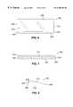
- FIG. 6shows a plan view of a rectangular embodiment of the prosthesis of the invention having a flat base.
- FIG. 7shows a front elevational view of the prosthesis illustrated in FIG. 6 .
- FIG. 8shows an end elevational view of the prosthesis shown in FIG. 6 .
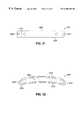
- FIG. 9shows a plan view of an embodiment of the prosthesis that is curved in the plane of the base.
- FIG. 10shows an end view of the prosthesis of FIG. 9 .
- FIG. 11illustrates a plan view of an alternate embodiment of the prosthesis of the invention.
- FIG. 12shows a front elevational view of the prosthesis illustrated in FIG. 11 .
- FIG. 13shows an end elevational view of the prosthesis of FIG. 11 .
- FIG. 14illustrates a plan view of an embodiment of the invention in which the ridge member extends beyond the end of the base member.
- FIG. 15shows a front elevational view of the prosthesis illustrated in FIG. 14 .
- FIG. 16 ashows an end elevational view of the prosthesis of FIG. 14, wherein the base prosthesis is tapered to the posterior edge.
- FIG. 16 bshows an end elevational view of a prosthesis similar to that shown in FIGS. 14, 15 and 16 a , wherein the base is not tapered.
- FIG. 17shows a plan view of an embodiment of the prosthesis of the invention wherein the prosthesis is hollow and made of an elastomeric material that is filled with a liquid.
- FIG. 18shows a front elevational view of the prosthesis illustrated in FIG. 17 .
- FIG. 19shows a cross sectional view of the prosthesis of FIG. 17 along the line 19 — 19 .
- FIG. 20shows an end elevational view of the prosthesis of FIG. 17 .
- FIG. 21illustrates a plan view of an embodiment of the prosthesis of the invention wherein the base is curved to match the curvature of the globe.
- FIG. 22shows a front elevational view of the prosthesis illustrated in FIG. 21 .
- FIG. 23shows an end elevational view of the prosthesis of FIG. 21 .
- FIG. 24illustrates a plan view of an alternate embodiment of the prosthesis of the invention having a curved surface adapted to contact the base of the scleral pocket.
- FIG. 25shows a front elevational view of the prosthesis illustrated in FIG. 24 .
- FIG. 26shows an end elevational view of the prosthesis of FIG. 24 .
- FIG. 27shows a cross-section of the prosthesis shown in FIG. 24 along the line 27 — 27 .
- FIG. 28shows a front elevational view of an eye having four prostheses of the type illustrated in FIGS. 24-27 implanted in the sclera thereof.
- FIG. 29shows a cross section of the eye of FIG. 28 along the line 29 — 29 .
- FIG. 30shows an enlarged view of the cross section of FIG. 29 in the region indicated by the circle 30 .
- FIG. 31illustrates a plan view of the prosthesis illustrated in FIG. 24 showing the prosthesis having portions that define a hole through which a suture may be passed.
- FIG. 32illustrates a front elevational view of the prosthesis illustrated in FIG. 31 .
- presbyopiais treated by increasing the effective working distance of the ciliary muscle. This is accomplished by increasing the distance between the ciliary muscle and the lens equator by increasing the diameter of the sclera in the region of the ciliary body.
- the effective working distance of the ciliary muscleis increased by implanting in pockets surgically formed in the sclera of the eye a plurality of prostheses designed to place an outward traction on the sclera in the region of the ciliary body.
- the relevant anatomy of the eye for locating the scleral pocketsmay be seen by reference to FIGS. 1-4.
- the outermost layer of the eye 100comprises the white, tough sclera 102 which encompasses most of the globe and the transparent cornea 104 , which constitutes the anterior segment of the outer coat.
- the circular junction of the cornea and sclerais the limbus 106 .
- the crystalline lens 108is enclosed in a thin membranous capsule and is located immediately posterior to the iris 112 , suspended centrally posterior to the pupil 114 on the optical axis of the eye.
- the lens 108is suspended by zonules extending between the lens capsule at the equator 110 of the lens 108 and the ciliary body 116 .
- the ciliary body 116lies just under the sclera 102 (i.e., just inwardly of the sclera 102 ) and is attached to the inner surface of the sclera 102 .
- the ciliary body 116lies generally in a plane 130 defined by the equator 110 of the lens 108 .
- the plane 130can also be extended to intersect the sclera 102 whereby it forms a generally circular intersection located about 2 millimeters posterior to the limbus 106 .
- the external muscles 118 of the eyeballcontrol the movement of the eye.
- a generally outwardly directed tractionis exerted on the sclera in the region of the ciliary body to expand the sclera 102 in that region.
- This expansion of the sclera 102produces a corresponding expansion of the attached ciliary body 116 and moves the ciliary body 116 outwardly away from the equator of the lens 108 , generally in the plane 130 of the equator 110 of the lens 108 .
- the sclera 102is preferably expanded approximately in the plane of the equator of the lens 108 .
- any expansion of the sclera 102 in the region of the ciliary body 116i.e., in the region of the sclera somewhat anterior or posterior to the plane of the equator 110 of the lens 108 is within the scope of the invention, provided that such expansion of the sclera 102 moves the ciliary body 116 away from the equator 110 of the lens 108 .
- the expansion of the sclerawill be accomplished in the region from about 1.5 millimeters anterior to the plane 130 of the equator of the lens 108 to about 2.5 millimeters posterior to that plane, i.e., from about 0.5 millimeters to about 4.5 millimeters posterior to the limbus 106 .
- the anterior margin 122 of a scleral pocket 120will be located in that region of the sclera.
- the prosthesis of the inventionis designed to apply an outwardly directed traction to the sclera at the general position of the anterior margin 122 of a scleral pocket 120 .
- the prosthesishas an elongated body with a first surface and a second surface each adapted to contact the base of the scleral pocket or the flap of the scleral pocket. The surfaces are spaced apart by the body of the prosthesis by a distance sufficient to cause the flap to exert an outward traction on at least the anterior margin of the scleral pocket, with the effect on the adjacent sclera and ciliary body as discussed above.
- the surfacescan have any suitable shape that accomplishes the purpose of the prosthesis, it is generally preferred that the prosthesis have a base having one major surface adapted to contact a major portion of the base or flap of the scleral pocket.
- the basetypically has an elongated planform and is oriented generally circumferentially with respect to the circle defined on the sclera by the intersection therewith of the plane 130 of the equator 110 of the lens 108 .
- the second, opposite, surface of the scleral prosthesismay be relatively broad in an antero-posterior dimension, or it may have a relatively narrow ridge extending along at least a substantial portion of the elongated planform.
- the prosthesismay be implanted within the scleral pocket or may extend beyond at least one end of the scleral pocket. It is preferable that the prosthesis be of a sufficient length to extend beyond the ends of the scleral pocket and contact the outer surface of the intact sclera.
- FIGS. 4 and 5The position of one embodiment of the prosthesis within a scleral pocket and its operation to expand the sclera are illustrated in FIGS. 4 and 5, showing a prosthesis of the type illustrated in FIGS. 6-8.
- the base member 202 of the prosthesis 200has a smooth exterior face 216 adapted to be placed in contact with the internal surface of the outer wall 128 of the scleral pocket 120 .
- the opposite, or interior, face 212 of the prosthesis 200is provided with a ridge 214 extending along a substantial portion of the length of the base 202 . This ridge bears against the inner wall 126 of the scleral pocket 120 . Accordingly, the sclera 102 at the anterior margin 122 of the scleral pocket 120 is elevated above its original level.
- the attached ciliary body 116is thereby also expanded away from the equator 110 of the lens 108 , and the working distance of the ciliary muscle is increased.
- FIGS. 6-8A first embodiment of the prosthesis of the invention is illustrated in FIGS. 6-8.
- FIG. 6shows a plan view of the inner face of the prosthesis 200 having a base 202 with an anterior edge 204 , a posterior edge 206 , and lateral ends 208 and 210 .
- the inner face 212is provided with a ridge 214 extending along the length of the major dimension of the elongated base 202
- FIG. 7shows a front elevational view of the prosthesis of FIG. 6 showing the flat, smooth outer surface 216 of the prosthesis.
- FIG. 8shows a side view of the prosthesis showing the outer surface 216 , the ridge 214 and a notch 218 on the inner surface 212 of the prosthesis.
- FIGS. 9-10illustrate a prosthesis of the invention having a curved planform adapted to be implanted in a scleral pocket that is curved to match the curvature of the eyeball.
- the prosthesis 300 of FIGS. 9-10has a generally planar base 302 , curved in the plane of the base 302 , having an anterior edge 304 , a posterior edge 306 , and lateral ends 308 and 310 .
- the inner face 312is provided with a ridge 314 extending along the length of the major dimension of the elongated curved base 302 .
- FIG. 10shows an side view of the prosthesis of FIG. 9 showing the outer face 316 , the ridge 314 and a notch 318 on the inner face 312 of the prosthesis.
- the curvature of the baseis chosen to provide at least an approximate match for the curvature of the adjacent structures on the surface of the sclera, e.g., the limbus 106 , adjusted for the distance of the scleral pocket 120 and prosthesis 300 from the limbus 106 .
- FIG. 3shows a front elevational view of an eye provided with curved scleral pockets 120 to accommodate a curved prosthesis 300 of the type illustrated in FIGS. 9 and 10.
- FIGS. 11-13show an embodiment of the invention wherein the anterior portion is tapered from the ridge to the anterior edge.
- FIG. 11shows a plan view ofthe prosthesis 400 having a base 402 with an anterior edge 404 , a posterior edge 406 , and lateral ends 408 and 410 .
- the outer face 416is smooth and adapted to be placed against the inner surface of the outer wall 128 of a scleral pocket 120 .
- the inner face 412is provided with aridge 414 extending along the length of the major dimension of the elongated base 402 .
- FIG. 12shows a front elevational view of the prosthesis of FIG. 11 showing the flat, smooth outer face 416 of the prosthesis.
- FIG. 13shows an end view of the prosthesis of FIG. 11 showing the outer face 416 and the ridge 414 on the inner face 412 of the prosthesis 400 .
- the ridge 414tapers toward the anterior edge 404 of the prosthesis.
- FIGS. 14-16show a preferred embodiment of the prosthesis in which the ridge member includes extensions beyond the ends of the base member which lie on the surface of the sclera adjacent to the scleral pocket and help to stabilize the prosthesis.
- FIG. 14shows a plan view of this embodiment 500 having a base 502 with an anterior edge 504 , a posterior edge 506 , and lateral ends 508 and 510 .
- the inner face 512is provided with a ridge 514 .
- the ends 508 and 510 of the ridge 514extend slightly beyond the ends of the base 502 . Accordingly, the ends 508 and 510 of the ridge 514 will extend beyond the ends of the pocket 120 and lie on the surface of the sclera 102 .
- FIG. 14shows a plan view of this embodiment 500 having a base 502 with an anterior edge 504 , a posterior edge 506 , and lateral ends 508 and 510 .
- the inner face 512is provided with a ridge 514
- FIG. 15shows a front elevational view of the prosthesis of FIG. 14 showing the flat, smooth outer face 516 of the prosthesis and the ends 508 and 510 of the ridge 514 extending beyond the ends of the base 502 .
- FIG. 16 ashows an end view of the prosthesis of FIG. 14 showing the smooth outer face 516 and the ridge 514 on the inner face 512 of the base 502 , as well as a notch 518 .
- FIG. 16 bshows an end view of an alternate embodiment of the prosthesis 500 wherein the base 502 does not taper all the way to the posterior edge 506 .
- the thickness of the posterior edge 506may vary from a relatively sharp posterior edge as shown in FIG. 16 a to a relatively thick posterior edge as shown in FIG. 16 b , or even thicker if it is advantageous.
- FIGS. 17-20illustrate an embodiment of the prosthesis that is hollow and made from a plastic or elastomeric material and filled with a liquid.
- FIG. 17shows a plan view of this embodiment 600 having a base 602 with an anterior edge 604 , a posterior edge 606 , and lateral ends 608 and 610 .
- the inner face 612is smoothly rounded and rises to a crest 614 that serves to support the prosthesis on the inner wall 126 of the scleral pocket 120 in the same way as the ridge member of other embodiments of the invention.
- FIG. 18shows a front elevational view of the prosthesis of FIG. 17 showing the flat, smooth outer face 616 of the prosthesis.
- FIG. 19shows a cross section of the prosthesis of FIG.
- FIG. 17taken along the line 19 — 19 .
- the cross-sectionshows the flexible wall 612 of the prosthesis as well as the flat outer face 616 , and the crest 614 .
- the cross sectionalso shows the filling liquid 620 .
- FIG. 20shows an end view of the prosthesis of FIG. 17 showing the outer face 616 and the crest or ridge 614 on the inner face 612 of the prosthesis 600 .
- the hollow prosthesisis filled with liquid, typically by injecting the liquid through an end 608 or 610 .
- the prosthesismaybe filled with more or less liquid in order to adjust the thickness between the outer face 616 and the crest or ridge 614 to provide more or less traction on the sclera at the anterior margin 122 of the scleral pocket or belt loop 120 .
- FIGS. 21-23illustrate an embodiment of the invention generally similar to that shown in FIGS. 6-8, having, however, a base in which the inner face of the prosthesis is curved to provide an approximate match to the curvature of the globe.
- FIG. 21shows a plan view of the inner face of the prosthesis 700 having a base 702 with an anterior edge 704 , a posterior edge 706 , and lateral ends 708 and 710 .
- the inner face 712is provided with a ridge 714 extending along the length of the major dimension of the elongated base 702 .
- FIG. 22shows a front elevational view of the prosthesis of FIG. 21 showing the curved, smooth outer surface 716 of the prosthesis.
- FIG. 23shows an end view of the prosthesis showing the outer surface 716 , the ridge 714 and a notch 718 on the curved inner surface 712 of the prosthesis.
- a preferred embodiment of the scleral prosthesisis that shown in FIGS. 9 and 10, wherein the anterior rim 304 and the posterior rim 306 are both generally circular arcs.
- the taper in the diameter of the segmentis preferably selected in an individual case to fit the globe in the region of the ciliary body. Accordingly, different sizes of segments will be provided wherein the radius of curvature of the anterior rim ranges from about 7.0 to about 10 millimeters in 0.50 millimeter increments. Accordingly, a preferred segment has a typical internal circular radius of curvature at its anterior portion of about 7.76 millimeters, at the position of the ridge of about 8.21 millimeters, and at the posterior rim of about 8.91 millimeters.
- the preferred segmenthas outer radius of curvature at its anterior portion of 8.02 millimeters, at its mid portion 8.47 millimeters, and at its base 8.94 millimeters. These measurements will vary depending on the size of the eye, the amount of rigidity required, and the strength of the material from which the segment is made.
- the preferred anterior chord length of the segmentis 5 millimeters.
- the axial width of the segmentwill typically be about 2 millimeters.
- FIGS. 24-27illustrate another preferred embodiment 800 of the scleral prosthesis of the invention having a curved surface to contact the base 126 of the scleral pocket and an elevated ridge or opposite surface to contact the inner side 128 of the flap of the scleral pocket 120 .
- This embodiment 800has a base 802 having a smooth surface 816 .
- the prosthesis 800has an anterior edge 804 and posterior edge 806 , which are relatively flat surfaces as shown.
- Opposite the base surface 816is an elevated surface or ridge 814 .
- the elevated surface or ridge 814is relatively broad in an antero-posterior, or axial, dimension. However, the ridge 814 may be relatively narrower or broader than shown.
- the prosthesis 800has lateral ends 808 and 810 .
- the prosthesis 800is shown as having a curved base surface 816 .
- the surface 816may also be flat or straight in the transverse dimension. However it is preferred that the surface 816 be curved as shown to generally match the curvature of the sclera in the zone adjacent to and contiguous with the ciliary body.
- FIG. 28shows a cross-section of the eye shown in FIG. 28, along the line 29 — 29 , showing the prostheses 800 in place in the scleral pockets 120 .
- FIG. 30shows an enlarged detail of the prosthesis 800 in the region defined by the circle 30 in FIG. 29 .
- the height of the prosthesis between base surface 816 and ridge 814is predetermined to elevate the flap of the scleral pocket or belt loop 120 sufficiently to exert an outwardly directed traction on at least the anterior margin 122 of the scleral pocket that is sufficient to elevate the sclera adjacent to the anterior margin 122 by an amount sufficient to accomplish the purpose of the invention, i.e., to increase the working distance of the ciliary muscle and thereby restore the amplitude of accommodation of the presbyopic eye.
- the distance between the major surface 816 and the second surface or ridge 814will be in the range of from about 0.3 millimeters to about 0.9 millimeters, preferably from about 0.5 millimeters to about 0.7 millimeters, and most preferably about 0.6 millimeters.
- the antero-posterior dimension of the prosthesis 800as measured between the surfaces 804 and 806 in the illustrated embodiment, may range from about 0.3 millimeters to about 0.9 millimeters, preferably from about 0.5 millimeters to about 0.7 millimeters, and most preferably about 0.6 millimeters.
- the distances between the surface 816 and ridge 814 and between anterior edge or surface 804 and posterior edge or surface 806may be varied as appropriate to fit in a scleral pocket of defined dimensions. These dimensions are chosen to accomplish the purpose of the invention, i.e., to produce an elevation of the sclera and associated ciliary body as discussed above. Consequently the actual cross sectional shape of the prosthesis may vary form that shown in FIGS. 24-27.
- the length of the scleral prosthesis 800which may be referred to as the transverse dimension as implanted in an eye, is chosen to provide an outward traction along a sufficient length of the circumference of the sclera of the eye in the zone encompassing the ciliary body to provide an effective amount of elevation of the sclera and attached ciliary body to accomplish the purpose of the invention.
- the length chosenwill also depend on whether the surgeon prefers to implant the prosthesis entirely within the length of the scleral pocket 120 , or have the ends of the prosthesis extend beyond the ends of the scleral pocket, as shown in FIG. 28 .
- ends 808 , 810 of the prosthesis 800extend beyond the lateral ends of the scleral pockets or belt loops, as shown in FIG. 28 .
- the ends 808 , 810bear on the intact sclera adjacent to the ends of the scleral belt loops to enhance the outward force exerted on the outer flap of the scleral pocket or belt loop 120 .
- the transverse dimension of the prosthesiswill range from about 3.0 millimeters to about 8.0 millimeters, preferably from about 3.5 millimeters to about 6.0 millimeters, more preferably from about 4.0 millimeters to about 5.0 millimeters, and most preferably about 4.5 millimeters.
- the dimensions of the prosthesisare adapted to the dimensions of the individual eye in which they are implanted, the dimensions being chosen to achieve an effective increase in the diameter of the sclera in the zone of the sclera adjacent to the ciliary body to produce an accompanying increase in the diameter of the ciliary body to provide an effective treatment for presbyopia and the other eye disorders discussed herein.
- the exact shape of the prosthesismay vary significantly from that shown in FIGS. 24-27.
- the dimensions and exact shape of the prosthesesare to be adapted to the eye in which they are to be implanted. Ordinarily a plurality, preferably four prostheses are implanted as shown in FIGS. 2, 3 , and 28 . However, more or fewer prostheses can be implanted. Ordinarily, all the prostheses implanted in one eye will be identical, but it is not excluded that prostheses of different shapes and dimensions may be implanted to achieve results desired by the surgeon.
- FIGS. 31-32illustrate an alternate embodiment in which scleral prosthesis 800 has portions that define a hole through which a suture may be passed.
- the scleral prosthesis of the inventionis made of a material that is sufficiently rigid to exert a force on the sclera sufficient to produce the radial expansion required by the method of the invention and that is physiologically acceptable for long-term implantation or contact with the ocular tissues.
- Such materialsare well-known in the surgical art and include suitable metals, ceramics, and synthetic resins.
- Suitable metalsinclude titanium, gold, platinum, stainless steel, tantalum and various surgically acceptable alloys, and the like.
- Suitable ceramicsmay include crystalline and vitreous materials such as porcelain, alumina, silica, silicon carbide, high-strength glasses and the like.
- Suitable synthetic materialsinclude physiologically inert materials such as poly(methyl methacrylate), polyethylene, polypropylene, poly(tetrafluoroethylene), polycarbonate, silicone resins and the like.
- the prosthesismay also be made of composite materials incorporating a synthetic resin or other matrix reinforced with fibers of high strength material such as glass fibers, boron fibers or the like.
- the segmentmay be made of glass-fiber-reinforced epoxy resin, carbon fiber-reinforced epoxy resin, carbon fiber-reinforced carbon (carbon—carbon), or the like.
- the segmentmay be made of a semi-rigid exterior and a liquid or gel filled interior so that the internal and external dimensions can be altered by injecting various amounts of liquid: water, saline, or silicone oil; or various amounts of a gel: silicone, collagen, or gelatin.
- the semi-rigid exteriormay be made of any of the already listed materials.
- the material of which the scleral prosthesis is mademay be adapted to the particular shape or design chosen for the prosthesis.
- a prosthesissuch as that shown in FIGS. 17-20 may be made of a material that can deflect and stretch under the internal pressure of the liquid or the like with which it is filled
- a prosthesis of the type shown in FIGS. 24-28, which receives support from regions of the intact sclera adjacent to the ends of the scleral pockets or belt loopsmay preferably be made of a relatively rigid material.
- a preferred material for the entire segmentis surgical grade poly(methyl methacrylate).
- the scleral prosthesis of the inventionmay be manufactured by any conventional technique appropriate to the material used, such as machining, injection molding, heat molding, compression molding and the like.
- the scleral prosthesismay be foldable to facilitate insertion into a scleral belt loop or made in a plurality of parts so that it can be assembled prior to use or may be installed separately to form a complete prosthesis.
- the surgeonlocates the proper region of the sclera to be expanded by measuring a distance of preferably 2.0 millimeters posterior of the limbus.
- a distance of preferably 2.0 millimeters posterior of the limbusAt 2.5 millimeters clockwise and counterclockwise from each of the 45° meridians of the eye, and 2 millimeters posterior to the limbus, partial scleral thickness radial incisions, i.e., antero-posterior incisions, are made which are 2 millimeters long and 350 microns deep.
- each pocket or belt loopis preferably centered over the 45° meridian of the eye.
- a prosthesisis then inserted in each of the four scleral belt loops. This produces symmetrical scleral expansion which will produce the desired result of increasing the effective working distance of the ciliary muscle.
- FIG. 1is an isometric view of an eye 100 having a globe 102 with the relevant exterior anatomical parts indicated as discussed above.
- FIGS. 2 and 3show front elevational views of an eye 100 showing the scleral pockets 120 formed at approximately the 45° meridians of the eye, i.e., approximately halfway between the vertical and horizontal meridians of the globe. This location is preferred because it avoids interference with structures of the eye that are located generally on the vertical and horizontal meridians.
- FIG. 3shows the use of curved scleral pockets 120 to permit the use of curved prostheses of the type illustrated in FIGS. 9 and 10.
- FIG. 2shows the use of straight scleral pockets 120 . Such straight pockets are somewhat simpler to prepare surgically. For many patients the use of straight prostheses can provide adequate treatment of their presbyopia.
- FIG. 4shows a cross-section of the eye, taken along the line 4 — 4 in FIG. 3, showing the placement of the prosthesis of the invention relative to the significant anatomical structures of the eye.
- This figureshows the general configuration of the scleral pockets 120 and the prostheses 200 of the type illustrated in FIGS. 6-8 in a preferred embodiment.
- the anterior margins 122 of the scleral pockets or belt loops 120are located approximately in the plane 130 of the equator 110 of the lens 108 .
- the ridge 210 of the prosthesiscauses the anterior portion of the pocket to be expanded somewhat more than the posterior portion. This places the sclera at the anterior margin of the pocket under a radial tension and causes it to expand somewhat from its normal diameter at that position.
- FIG. 5shows an enlarged portion of one of the scleral pockets 120 with adjacent anatomical structures. It shows the relation of the scleral pocket 120 to the underlying structures and its location just posterior to the equator of the lens 108 and overlying the ciliary body 116 .
- the method of the invention which increases the amplitude of accommodationmay also be of benefit in treatment of hyperopia in certain patients.
- Some youthful hype ropescan achieve relatively normal vision by compensating for their hyperopia through the natural accommodative ability of the eye. However, as this ability declines with age, they find that it becomes more difficult to attain normal vision by this process, and they begin to experience headaches and other symptoms, even at an age somewhat less than usual for the onset of presbyopia.
- increasing the amplitude of accommodation by the method of this inventionwould be useful in restoring the ability of these patients to compensate for their hyperopia.
- the method of this inventionalso has utility in the treatment of primary open-angle glaucoma, which shows a correlation with age in certain individuals. It has been found that, in general, intraocular pressure (IOP) exhibits a linear increase with increasing age. (Armaly, M. F., On the distribution of applanation pressure I. Statistical features and the effect of age, sex, and family history of glaucoma, Archives of Ophthalmology, Vol. 73, pp. 11-18 (1965)). Among the general population is found a group of individuals who develop abnormally high intraocular pressures as a result of primary open angle glaucoma, a disease which is one of the most prevalent causes of blindness in the world.
- the linear increase in IOP with ageis a direct result of the decrease in distance between the lens equator and the ciliary muscle and the resulting linear decrease in the effective pull of the ciliary muscle. Since the ciliary muscle inserts into the trabecular meshwork, the decrease in pull will decrease the size of the trabeculum and/or the drainage pores and result in a linear increase of intraocular pressure with age.
- the patients who develop primary open angle glaucomamay have a congenital predilection to narrower pores, protein deposition in the pores, and/or a smaller trabecular meshwork, so that when the ability of the ciliary muscle to exert force declines, after the age of 40 or thereabouts, they tend to develop excessively elevated IOP.
- the method of the inventionwhich increases the effective working distance of the ciliary muscle, and thereby increases the force that it can exert when it contracts, restores the level of force which the ciliary muscle exerts on the trabecular meshwork to a value characteristic of a more youthful eye. In this way it is expected that the tendency of an eye that is disposed to develop primary open angle glaucoma as it ages would be overcome and the onset of this disease would be prevented or at least postponed.
Landscapes
- Health & Medical Sciences (AREA)
- Ophthalmology & Optometry (AREA)
- Vascular Medicine (AREA)
- Life Sciences & Earth Sciences (AREA)
- Veterinary Medicine (AREA)
- Public Health (AREA)
- General Health & Medical Sciences (AREA)
- Engineering & Computer Science (AREA)
- Biomedical Technology (AREA)
- Heart & Thoracic Surgery (AREA)
- Animal Behavior & Ethology (AREA)
- Transplantation (AREA)
- Surgery (AREA)
- Nuclear Medicine, Radiotherapy & Molecular Imaging (AREA)
- Cardiology (AREA)
- Oral & Maxillofacial Surgery (AREA)
- Optics & Photonics (AREA)
- Physics & Mathematics (AREA)
- Prostheses (AREA)
- Materials For Medical Uses (AREA)
Abstract
Description
Claims (60)
Priority Applications (4)
| Application Number | Priority Date | Filing Date | Title |
|---|---|---|---|
| US09/061,168US6280468B1 (en) | 1997-10-08 | 1998-04-16 | Scleral prosthesis for treatment of presbyopia and other eye disorders |
| US09/863,006US6991650B2 (en) | 1997-10-08 | 2001-05-22 | Scleral expansion device having duck bill |
| US09/940,722US7780727B2 (en) | 1997-10-08 | 2001-08-27 | Scleral prosthesis for treatment of presbyopia and other eye disorders |
| US11/252,369US20060095126A1 (en) | 1997-10-08 | 2005-10-17 | Scleral expansion device having duck bill |
Applications Claiming Priority (2)
| Application Number | Priority Date | Filing Date | Title |
|---|---|---|---|
| US08/946,975US6007578A (en) | 1997-10-08 | 1997-10-08 | Scleral prosthesis for treatment of presbyopia and other eye disorders |
| US09/061,168US6280468B1 (en) | 1997-10-08 | 1998-04-16 | Scleral prosthesis for treatment of presbyopia and other eye disorders |
Related Parent Applications (2)
| Application Number | Title | Priority Date | Filing Date |
|---|---|---|---|
| US08/946,975Continuation-In-PartUS6007578A (en) | 1997-10-08 | 1997-10-08 | Scleral prosthesis for treatment of presbyopia and other eye disorders |
| US09/863,006Continuation-In-PartUS6991650B2 (en) | 1997-10-08 | 2001-05-22 | Scleral expansion device having duck bill |
Related Child Applications (4)
| Application Number | Title | Priority Date | Filing Date |
|---|---|---|---|
| US09/472,535Continuation-In-PartUS6299640B1 (en) | 1997-10-08 | 1999-12-27 | Scleral prosthesis for treatment of presbyopia and other eye disorders |
| US09/589,626Continuation-In-PartUS7416560B1 (en) | 1997-10-08 | 2000-06-07 | Scleral prosthesis for treatment of presbyopia and other eye disorders |
| US09/863,006Continuation-In-PartUS6991650B2 (en) | 1997-10-08 | 2001-05-22 | Scleral expansion device having duck bill |
| US09/940,722ContinuationUS7780727B2 (en) | 1997-10-08 | 2001-08-27 | Scleral prosthesis for treatment of presbyopia and other eye disorders |
Publications (1)
| Publication Number | Publication Date |
|---|---|
| US6280468B1true US6280468B1 (en) | 2001-08-28 |
Family
ID=25485282
Family Applications (5)
| Application Number | Title | Priority Date | Filing Date |
|---|---|---|---|
| US08/946,975Expired - LifetimeUS6007578A (en) | 1997-10-08 | 1997-10-08 | Scleral prosthesis for treatment of presbyopia and other eye disorders |
| US09/061,168Expired - LifetimeUS6280468B1 (en) | 1997-10-08 | 1998-04-16 | Scleral prosthesis for treatment of presbyopia and other eye disorders |
| US09/472,535Expired - LifetimeUS6299640B1 (en) | 1997-10-08 | 1999-12-27 | Scleral prosthesis for treatment of presbyopia and other eye disorders |
| US09/940,722Expired - Fee RelatedUS7780727B2 (en) | 1997-10-08 | 2001-08-27 | Scleral prosthesis for treatment of presbyopia and other eye disorders |
| US09/972,533AbandonedUS20020010509A1 (en) | 1997-10-08 | 2001-10-08 | Scleral prosthesis for treatment of presbyopia and other eye disorders |
Family Applications Before (1)
| Application Number | Title | Priority Date | Filing Date |
|---|---|---|---|
| US08/946,975Expired - LifetimeUS6007578A (en) | 1997-10-08 | 1997-10-08 | Scleral prosthesis for treatment of presbyopia and other eye disorders |
Family Applications After (3)
| Application Number | Title | Priority Date | Filing Date |
|---|---|---|---|
| US09/472,535Expired - LifetimeUS6299640B1 (en) | 1997-10-08 | 1999-12-27 | Scleral prosthesis for treatment of presbyopia and other eye disorders |
| US09/940,722Expired - Fee RelatedUS7780727B2 (en) | 1997-10-08 | 2001-08-27 | Scleral prosthesis for treatment of presbyopia and other eye disorders |
| US09/972,533AbandonedUS20020010509A1 (en) | 1997-10-08 | 2001-10-08 | Scleral prosthesis for treatment of presbyopia and other eye disorders |
Country Status (20)
| Country | Link |
|---|---|
| US (5) | US6007578A (en) |
| EP (1) | EP1021146B1 (en) |
| JP (1) | JP3828583B2 (en) |
| KR (1) | KR100525498B1 (en) |
| CN (1) | CN1267202A (en) |
| AR (1) | AR013679A1 (en) |
| AT (1) | ATE293417T1 (en) |
| AU (1) | AU7693798A (en) |
| BR (1) | BR9806304A (en) |
| CA (1) | CA2274260C (en) |
| DE (1) | DE69829866T2 (en) |
| EA (1) | EA002476B1 (en) |
| ES (1) | ES2242283T3 (en) |
| HU (1) | HUP0003806A3 (en) |
| ID (1) | ID21957A (en) |
| IL (1) | IL130295A (en) |
| NO (1) | NO318462B1 (en) |
| NZ (2) | NZ336063A (en) |
| WO (1) | WO1999017691A1 (en) |
| ZA (2) | ZA984634B (en) |
Cited By (78)
| Publication number | Priority date | Publication date | Assignee | Title |
|---|---|---|---|---|
| US6510600B2 (en) | 1997-11-20 | 2003-01-28 | Optonol, Ltd. | Method for manufacturing a flow regulating implant |
| WO2003015667A1 (en) | 2001-08-03 | 2003-02-27 | David Castillejos | Method and intra sclera implant for treatment of glaucoma and presbyopia |
| WO2003020176A1 (en)* | 2001-08-31 | 2003-03-13 | Duckworth & Kent Limited | Ophtalmic tissue barrier |
| US20030060748A1 (en)* | 2001-01-19 | 2003-03-27 | Georges Baikoff | Techniques and implants for correcting presbyopia |
| WO2003020190A3 (en)* | 2001-08-31 | 2003-05-30 | Duckworth & Kent Ltd | Ophthalmic devices and procedures |
| US20040024453A1 (en)* | 2001-08-03 | 2004-02-05 | Glaucoma Research Technologies, Inc. | Method and intra sclera implant for treatment of glaucoma and presbyopia |
| FR2844703A1 (en)* | 2002-09-25 | 2004-03-26 | Alain Nicolas Gilg | Implant for treating presbyopia comprises a closed tubular envelope made of fluid-impermeable elastic material in the form of a ring filled with an incompressible fluid |
| US6726664B2 (en) | 1999-06-02 | 2004-04-27 | Optonol Ltd. | Flow control device, introducer and method of implanting |
| US20040088048A1 (en)* | 1995-05-14 | 2004-05-06 | Jacob Richter | Intraocular implant, delivery device, and method of implantation |
| WO2004066870A3 (en)* | 2003-01-27 | 2004-09-30 | Restorvision Ltd | Combined iol and scleral implants and method of use |
| US20050106270A1 (en)* | 2003-10-06 | 2005-05-19 | Devore Dale P. | Chemical treatment of in vivo tissue to alter charge and net charge density characteristics |
| US6991650B2 (en) | 1997-10-08 | 2006-01-31 | Refocus Ocular, Inc. | Scleral expansion device having duck bill |
| US7037335B2 (en) | 2002-11-19 | 2006-05-02 | Eagle Vision, Inc. | Bulbous scleral implants for the treatment of eye disorders such as presbyopia and glaucoma |
| US20060116760A1 (en)* | 2004-11-30 | 2006-06-01 | Human Technology Group, Inc. | Apparatus and method for treating presbyopia and other eye conditions |
| US20060241750A1 (en)* | 2001-05-22 | 2006-10-26 | Ras Holding Corp | Scleral expansion device having duck bill |
| US20070027537A1 (en)* | 2002-08-02 | 2007-02-01 | David Castillejos | Method and intra-sclera implant for treatment of glaucoma and presbyopia |
| US20070073324A1 (en)* | 2005-09-29 | 2007-03-29 | Georges Baikoff | Method and surgical tool for forming scleral tunnels |
| US20070162116A1 (en)* | 2006-01-11 | 2007-07-12 | Georges Baikoff | Method for locating optimum presbyopia implant location |
| US20070235043A1 (en)* | 2006-04-10 | 2007-10-11 | Georges Baikoff | Presbyopia treatment by weakening the zonula |
| WO2008008391A2 (en) | 2006-07-11 | 2008-01-17 | Refocus Group, Inc. | Apparatus for securing ocular tissue |
| US20080108933A1 (en)* | 2006-06-30 | 2008-05-08 | Dao-Yi Yu | Methods, Systems and Apparatus for Relieving Pressure in an Organ |
| US20090099654A1 (en)* | 2007-08-02 | 2009-04-16 | Refocus Group, Inc. | Scleral prosthesis having crossbars for treating presbyopia and other eye disorders |
| US7655002B2 (en) | 1996-03-21 | 2010-02-02 | Second Sight Laser Technologies, Inc. | Lenticular refractive surgery of presbyopia, other refractive errors, and cataract retardation |
| US7862531B2 (en) | 2004-06-25 | 2011-01-04 | Optonol Ltd. | Flow regulating implants |
| US8109896B2 (en) | 2008-02-11 | 2012-02-07 | Optonol Ltd. | Devices and methods for opening fluid passageways |
| US8262646B2 (en) | 2006-01-20 | 2012-09-11 | Lensar, Inc. | System and method for providing the shaped structural weakening of the human lens with a laser |
| US8308701B2 (en) | 2010-11-15 | 2012-11-13 | Aquesys, Inc. | Methods for deploying intraocular shunts |
| US8313454B2 (en) | 1997-11-20 | 2012-11-20 | Optonol Ltd. | Fluid drainage device, delivery device, and associated methods of use and manufacture |
| US8337550B2 (en) | 2006-07-11 | 2012-12-25 | Refocus Ocular, Inc. | Scleral prosthesis for treating presbyopia and other eye disorders and related devices and methods |
| US8382745B2 (en) | 2009-07-24 | 2013-02-26 | Lensar, Inc. | Laser system and method for astigmatic corrections in association with cataract treatment |
| US8465478B2 (en) | 2009-07-24 | 2013-06-18 | Lensar, Inc. | System and method for performing LADAR assisted procedures on the lens of an eye |
| US8480659B2 (en) | 2008-07-25 | 2013-07-09 | Lensar, Inc. | Method and system for removal and replacement of lens material from the lens of an eye |
| US8500723B2 (en) | 2008-07-25 | 2013-08-06 | Lensar, Inc. | Liquid filled index matching device for ophthalmic laser procedures |
| US8556425B2 (en) | 2010-02-01 | 2013-10-15 | Lensar, Inc. | Purkinjie image-based alignment of suction ring in ophthalmic applications |
| US8585629B2 (en) | 2010-11-15 | 2013-11-19 | Aquesys, Inc. | Systems for deploying intraocular shunts |
| USD694890S1 (en) | 2010-10-15 | 2013-12-03 | Lensar, Inc. | Laser system for treatment of the eye |
| USD695408S1 (en) | 2010-10-15 | 2013-12-10 | Lensar, Inc. | Laser system for treatment of the eye |
| US8617146B2 (en) | 2009-07-24 | 2013-12-31 | Lensar, Inc. | Laser system and method for correction of induced astigmatism |
| US8663303B2 (en) | 2010-11-15 | 2014-03-04 | Aquesys, Inc. | Methods for deploying an intraocular shunt from a deployment device and into an eye |
| US8721702B2 (en) | 2010-11-15 | 2014-05-13 | Aquesys, Inc. | Intraocular shunt deployment devices |
| US8758332B2 (en) | 2009-07-24 | 2014-06-24 | Lensar, Inc. | Laser system and method for performing and sealing corneal incisions in the eye |
| US8758290B2 (en) | 2010-11-15 | 2014-06-24 | Aquesys, Inc. | Devices and methods for implanting a shunt in the suprachoroidal space |
| US8765210B2 (en) | 2011-12-08 | 2014-07-01 | Aquesys, Inc. | Systems and methods for making gelatin shunts |
| US8801186B2 (en) | 2010-10-15 | 2014-08-12 | Lensar, Inc. | System and method of scan controlled illumination of structures within an eye |
| US8801766B2 (en) | 2010-11-15 | 2014-08-12 | Aquesys, Inc. | Devices for deploying intraocular shunts |
| US8828070B2 (en) | 2010-11-15 | 2014-09-09 | Aquesys, Inc. | Devices for deploying intraocular shunts |
| US8852136B2 (en) | 2011-12-08 | 2014-10-07 | Aquesys, Inc. | Methods for placing a shunt into the intra-scleral space |
| US8852256B2 (en) | 2010-11-15 | 2014-10-07 | Aquesys, Inc. | Methods for intraocular shunt placement |
| US8852137B2 (en) | 2010-11-15 | 2014-10-07 | Aquesys, Inc. | Methods for implanting a soft gel shunt in the suprachoroidal space |
| US8911496B2 (en) | 2006-07-11 | 2014-12-16 | Refocus Group, Inc. | Scleral prosthesis for treating presbyopia and other eye disorders and related devices and methods |
| US8974511B2 (en) | 2010-11-15 | 2015-03-10 | Aquesys, Inc. | Methods for treating closed angle glaucoma |
| US9017276B2 (en) | 2010-11-15 | 2015-04-28 | Aquesys, Inc. | Shunt placement through the sclera |
| US20150202439A1 (en)* | 2006-08-18 | 2015-07-23 | Second Sight Medical Products, Inc. | Package for an Implantable Neural Stimulation Device |
| USRE45625E1 (en) | 2004-08-23 | 2015-07-28 | Reading Enhancement Co. | Reading enhancement device for preventing and treating presbyopia of the eye |
| US9095411B2 (en) | 2010-11-15 | 2015-08-04 | Aquesys, Inc. | Devices for deploying intraocular shunts |
| US9125723B2 (en) | 2013-02-19 | 2015-09-08 | Aquesys, Inc. | Adjustable glaucoma implant |
| US9180051B2 (en) | 2006-01-20 | 2015-11-10 | Lensar Inc. | System and apparatus for treating the lens of an eye |
| US9375349B2 (en) | 2006-01-20 | 2016-06-28 | Lensar, Llc | System and method for providing laser shot patterns to the lens of an eye |
| US9393154B2 (en) | 2011-10-28 | 2016-07-19 | Raymond I Myers | Laser methods for creating an antioxidant sink in the crystalline lens for the maintenance of eye health and physiology and slowing presbyopia development |
| US9474594B2 (en) | 2012-02-22 | 2016-10-25 | Ira H. Schachar | Device and method for treatment of retinal detachment and other maladies of the eye |
| US9545338B2 (en) | 2006-01-20 | 2017-01-17 | Lensar, Llc. | System and method for improving the accommodative amplitude and increasing the refractive power of the human lens with a laser |
| US9585790B2 (en) | 2013-11-14 | 2017-03-07 | Aquesys, Inc. | Intraocular shunt inserter |
| US9610195B2 (en) | 2013-02-27 | 2017-04-04 | Aquesys, Inc. | Intraocular shunt implantation methods and devices |
| US9808373B2 (en) | 2013-06-28 | 2017-11-07 | Aquesys, Inc. | Intraocular shunt implantation |
| US9889043B2 (en) | 2006-01-20 | 2018-02-13 | Lensar, Inc. | System and apparatus for delivering a laser beam to the lens of an eye |
| US10080682B2 (en) | 2011-12-08 | 2018-09-25 | Aquesys, Inc. | Intrascleral shunt placement |
| US10085884B2 (en) | 2006-06-30 | 2018-10-02 | Aquesys, Inc. | Intraocular devices |
| US10159600B2 (en) | 2013-02-19 | 2018-12-25 | Aquesys, Inc. | Adjustable intraocular flow regulation |
| US10342700B2 (en) | 2012-02-22 | 2019-07-09 | Ira H. Schachar | Device and method for treatment of retinal detachment and other maladies of the eye |
| US10463537B2 (en) | 2015-06-03 | 2019-11-05 | Aquesys Inc. | Ab externo intraocular shunt placement |
| US10463541B2 (en) | 2011-03-25 | 2019-11-05 | Lensar, Inc. | System and method for correcting astigmatism using multiple paired arcuate laser generated corneal incisions |
| US10667947B2 (en) | 2016-06-02 | 2020-06-02 | Aquesys, Inc. | Intraocular drug delivery |
| US10842671B2 (en) | 2010-11-15 | 2020-11-24 | Aquesys, Inc. | Intraocular shunt placement in the suprachoroidal space |
| US10952898B2 (en) | 2018-03-09 | 2021-03-23 | Aquesys, Inc. | Intraocular shunt inserter |
| US11135089B2 (en) | 2018-03-09 | 2021-10-05 | Aquesys, Inc. | Intraocular shunt inserter |
| WO2021236186A1 (en) | 2020-05-18 | 2021-11-25 | Refocus Group, Inc. | Apparatus and method for securing ocular tissue and providing surgical tool positioning points |
| US11246753B2 (en) | 2017-11-08 | 2022-02-15 | Aquesys, Inc. | Manually adjustable intraocular flow regulation |
| US20230381020A1 (en)* | 2022-05-25 | 2023-11-30 | R. Philip Doss | Curved microtube for treating glaucoma |
Families Citing this family (50)
| Publication number | Priority date | Publication date | Assignee | Title |
|---|---|---|---|---|
| US6135118A (en)* | 1997-05-12 | 2000-10-24 | Dailey; James P. | Treatment with magnetic fluids |
| US6007578A (en)* | 1997-10-08 | 1999-12-28 | Ras Holding Corp | Scleral prosthesis for treatment of presbyopia and other eye disorders |
| FR2784287B1 (en) | 1998-10-13 | 2000-12-08 | Georges Baikoff | SCLERAL EXPANSION SEGMENT |
| FR2787991B1 (en)* | 1998-12-31 | 2001-05-25 | Medicale De Prec S M P Sa Soc | DEVICE FOR TREATING PRESBYGIA OR OTHER EYE CONDITION |
| PL352229A1 (en) | 1999-06-07 | 2003-08-11 | Ras Holding Corp | Prosthesis of sclera for treatment of presbyopia and other sight disorders |
| US7008396B1 (en) | 1999-09-03 | 2006-03-07 | Restorvision, Inc. | Ophthalmic device and method of manufacture and use |
| US7635388B1 (en)* | 2000-05-04 | 2009-12-22 | Tyler Thomas D | Device and method for incremental correction of sight disorders and occular diseases |
| US6511508B1 (en)* | 2000-08-04 | 2003-01-28 | Environmental Robots, Inc. | Surgical correction of human eye refractive errors by active composite artificial muscle implants |
| US7060094B2 (en) | 2000-08-07 | 2006-06-13 | Ophthalmotronics, Inc. | Accommodating zonular mini-bridge implants |
| US6517555B1 (en) | 2000-09-05 | 2003-02-11 | Clear Sight, Inc. | Method for treating presbyopia |
| CA2421948C (en) | 2000-09-12 | 2009-12-22 | Anamed, Inc. | System for packaging and handling an implant and method of use |
| US8668735B2 (en) | 2000-09-12 | 2014-03-11 | Revision Optics, Inc. | Corneal implant storage and delivery devices |
| FR2819712B1 (en) | 2001-01-19 | 2005-12-23 | Georges Baikoff | CORRECTIVE ELEMENT OF PRESBYOPIA |
| AR032840A1 (en) | 2001-02-23 | 2003-11-26 | Ras Holding Corp | SURGICAL SHEET USED WITH A SURGICAL INSTRUMENT TO MAKE INCISIONS IN IMPLANTS IN EYE SCLERTIC |
| WO2002076356A2 (en)* | 2001-03-22 | 2002-10-03 | Newlens, Llc | Presbyopia treatment by scleral compression |
| US7338506B2 (en)* | 2001-09-05 | 2008-03-04 | Caro Nicholas C | Scleral clip and procedures for using same |
| US20040002756A1 (en)* | 2002-05-09 | 2004-01-01 | Georges Baikoff | Corrective element for presbyopia |
| AU2003241530A1 (en)* | 2002-05-20 | 2003-12-12 | Refocus Group, Inc. | System and method for determining a position for a scleral pocket for a scleral prosthesis |
| FR2843015B1 (en)* | 2002-08-01 | 2005-06-10 | Laredo Fernand | IMPLANT FOR THE TREATMENT OF PRESBYOPIA |
| US20050197697A1 (en)* | 2003-01-13 | 2005-09-08 | Georges Baikoff | Corrective element for presbyopia |
| ES2523454T3 (en) | 2003-06-16 | 2014-11-26 | Solx, Inc. | Referral for the treatment of glaucoma |
| US20060069340A1 (en)* | 2003-06-16 | 2006-03-30 | Solx, Inc. | Shunt for the treatment of glaucoma |
| US20040260395A1 (en)* | 2003-06-19 | 2004-12-23 | Boxer Wachler Brian S. | Ophthalmological zonular stretch segment for treating presbyopia |
| US10835371B2 (en) | 2004-04-30 | 2020-11-17 | Rvo 2.0, Inc. | Small diameter corneal inlay methods |
| US8057541B2 (en) | 2006-02-24 | 2011-11-15 | Revision Optics, Inc. | Method of using small diameter intracorneal inlays to treat visual impairment |
| US7776086B2 (en) | 2004-04-30 | 2010-08-17 | Revision Optics, Inc. | Aspherical corneal implant |
| US20060004386A1 (en)* | 2004-07-01 | 2006-01-05 | Caro Nicholas C | Ophthalmic clip and associated surgical method |
| US20060235513A1 (en)* | 2005-04-18 | 2006-10-19 | Price Francis W Jr | Corneal implants and methods of use |
| WO2007076533A2 (en)* | 2005-12-29 | 2007-07-05 | Caro Nicholas C | Ophthalmic clip and associated surgical method |
| US10555805B2 (en) | 2006-02-24 | 2020-02-11 | Rvo 2.0, Inc. | Anterior corneal shapes and methods of providing the shapes |
| US8568478B2 (en) | 2006-09-21 | 2013-10-29 | Abbott Medical Optics Inc. | Intraocular lenses for managing glare, adhesion, and cell migration |
| US20080077238A1 (en)* | 2006-09-21 | 2008-03-27 | Advanced Medical Optics, Inc. | Intraocular lenses for managing glare, adhesion, and cell migration |
| US8123803B2 (en)* | 2007-01-24 | 2012-02-28 | Mohsen Shaninpoor | System and device for correcting hyperopia and presbyopia |
| US9549848B2 (en) | 2007-03-28 | 2017-01-24 | Revision Optics, Inc. | Corneal implant inserters and methods of use |
| US8162953B2 (en) | 2007-03-28 | 2012-04-24 | Revision Optics, Inc. | Insertion system for corneal implants |
| US9271828B2 (en) | 2007-03-28 | 2016-03-01 | Revision Optics, Inc. | Corneal implant retaining devices and methods of use |
| US8201942B2 (en)* | 2008-04-02 | 2012-06-19 | Refocus Group, Inc. | System and method for identifying a position to insert a scleral prosthesis into an eye |
| JP2011516180A (en) | 2008-04-04 | 2011-05-26 | レヴィジオン・オプティックス・インコーポレーテッド | Corneal inlay design and method for correcting vision |
| US9539143B2 (en) | 2008-04-04 | 2017-01-10 | Revision Optics, Inc. | Methods of correcting vision |
| JP2012512668A (en)* | 2008-11-19 | 2012-06-07 | リフォーカス グループ、インコーポレイテッド | Artificial intraocular lens, modified native lens, or refilled native lens capsule with one or more scleral prostheses to improve performance |
| US8357196B2 (en)* | 2009-11-18 | 2013-01-22 | Abbott Medical Optics Inc. | Mark for intraocular lenses |
| US8469948B2 (en) | 2010-08-23 | 2013-06-25 | Revision Optics, Inc. | Methods and devices for forming corneal channels |
| US8597318B2 (en) | 2011-08-08 | 2013-12-03 | Refocus Group, Inc. | Apparatus and method for forming incisions in ocular tissue |
| WO2013059813A1 (en) | 2011-10-21 | 2013-04-25 | Revision Optics, Inc. | Corneal implant storage and delivery devices |
| CN104334131B (en)* | 2012-03-27 | 2017-06-16 | 杜克大学 | Ocular drug delivery device and application method |
| CN105960454B (en)* | 2013-12-11 | 2020-10-30 | 住友化学株式会社 | Method for preparing ciliary limbus-like structures |
| CN106465549A (en)* | 2014-04-09 | 2017-02-22 | 通用汽车环球科技运作有限责任公司 | Systems and methods for reinforced adhesive bonding |
| AU2015385773A1 (en) | 2015-03-12 | 2017-10-05 | Revision Optics, Inc. | Methods of correcting vision |
| RU2649449C1 (en)* | 2017-05-04 | 2018-04-03 | Антон Алексеевич Тучин | Multi-layered ocular prosthesis based on silicon dioxide |
| JP2020531144A (en) | 2017-08-23 | 2020-11-05 | リフォーカス グループ、インコーポレイテッド | Surgical tools for forming incisions in ocular tissue, as well as related devices and methods, with a tip that provides visibility. |
Citations (13)
| Publication number | Priority date | Publication date | Assignee | Title |
|---|---|---|---|---|
| US2952023A (en) | 1957-03-19 | 1960-09-13 | Rosen Hyman | Corneal fabrication |
| US3064643A (en) | 1960-12-13 | 1962-11-20 | James H Dixon | Scleral brace |
| US3454966A (en) | 1965-02-11 | 1969-07-15 | Hyman Rosen | Prosthetic corneal fabrication with heating and cooling means to facilitate attachment to corneal tissue |
| US4521210A (en) | 1982-12-27 | 1985-06-04 | Wong Vernon G | Eye implant for relieving glaucoma, and device and method for use therewith |
| US4946436A (en) | 1989-11-17 | 1990-08-07 | Smith Stewart G | Pressure-relieving device and process for implanting |
| US4976719A (en) | 1988-11-21 | 1990-12-11 | Siepser Steven B | Device used to change corneal curvature |
| US5354331A (en) | 1992-07-15 | 1994-10-11 | Schachar Ronald A | Treatment of presbyopia and other eye disorders |
| US5443505A (en) | 1993-11-15 | 1995-08-22 | Oculex Pharmaceuticals, Inc. | Biocompatible ocular implants |
| US5520631A (en) | 1994-07-22 | 1996-05-28 | Wound Healing Of Oklahoma | Method and apparatus for lowering the intraocular pressure of an eye |
| US5558630A (en) | 1994-12-30 | 1996-09-24 | Fisher; Bret L. | Intrascleral implant and method for the regulation of intraocular pressure |
| USRE35390E (en) | 1989-11-17 | 1996-12-03 | Smith; Stewart G. | Pressure relieving device and process for implanting |
| US5879319A (en)* | 1994-06-22 | 1999-03-09 | Chauvin Opsia | Sclerotomy implant |
| US6007578A (en)* | 1997-10-08 | 1999-12-28 | Ras Holding Corp | Scleral prosthesis for treatment of presbyopia and other eye disorders |
Family Cites Families (8)
| Publication number | Priority date | Publication date | Assignee | Title |
|---|---|---|---|---|
| US35390A (en)* | 1862-05-27 | Improved guide and support for scroll-saws | ||
| US4452235A (en) | 1982-01-04 | 1984-06-05 | Reynolds Alvin E | Method for corneal curvature adjustment |
| US4961744A (en) | 1982-01-04 | 1990-10-09 | Keravision, Inc. | Holder for inserting corneal curvature adjustable ring |
| GB8623661D0 (en)* | 1986-10-02 | 1986-11-05 | Darougar S | Ocular insert |
| US5146933A (en) | 1991-09-20 | 1992-09-15 | Dow Corning Wright Corporation | Implantable prosthetic device and tethered inflation valve for volume |
| SG52643A1 (en) | 1993-08-02 | 1998-09-28 | Keravision Inc | Segmented preformed intrastromal corneal insert |
| ATE240698T1 (en)* | 1995-06-07 | 2003-06-15 | Keravision Inc | RADIAL INTRASTROMAL CORNEA IMPLANT |
| FR2784287B1 (en)* | 1998-10-13 | 2000-12-08 | Georges Baikoff | SCLERAL EXPANSION SEGMENT |
- 1997
- 1997-10-08USUS08/946,975patent/US6007578A/ennot_activeExpired - Lifetime
- 1998
- 1998-04-16USUS09/061,168patent/US6280468B1/ennot_activeExpired - Lifetime
- 1998-05-21BRBR9806304-9Apatent/BR9806304A/ennot_activeIP Right Cessation
- 1998-05-21CNCN98802230Apatent/CN1267202A/enactivePending
- 1998-05-21ILIL13029598Apatent/IL130295A/ennot_activeIP Right Cessation
- 1998-05-21ESES98924867Tpatent/ES2242283T3/ennot_activeExpired - Lifetime
- 1998-05-21EPEP98924867Apatent/EP1021146B1/ennot_activeExpired - Lifetime
- 1998-05-21EAEA199900525Apatent/EA002476B1/ennot_activeIP Right Cessation
- 1998-05-21AUAU76937/98Apatent/AU7693798A/ennot_activeAbandoned
- 1998-05-21WOPCT/US1998/010582patent/WO1999017691A1/enactiveIP Right Grant
- 1998-05-21DEDE69829866Tpatent/DE69829866T2/ennot_activeExpired - Lifetime
- 1998-05-21ATAT98924867Tpatent/ATE293417T1/ennot_activeIP Right Cessation
- 1998-05-21IDIDW990465Apatent/ID21957A/enunknown
- 1998-05-21JPJP52172399Apatent/JP3828583B2/ennot_activeExpired - Lifetime
- 1998-05-21KRKR10-1999-7005060Apatent/KR100525498B1/ennot_activeExpired - Lifetime
- 1998-05-21NZNZ336063Apatent/NZ336063A/ennot_activeIP Right Cessation
- 1998-05-21CACA2274260Apatent/CA2274260C/ennot_activeExpired - Lifetime
- 1998-05-21HUHU0003806Apatent/HUP0003806A3/enunknown
- 1998-05-29ZAZA984634Apatent/ZA984634B/enunknown
- 1998-10-07ZAZA989149Apatent/ZA989149B/enunknown
- 1998-10-08ARARP980105030Apatent/AR013679A1/enactiveIP Right Grant
- 1999
- 1999-06-07NONO19992755Apatent/NO318462B1/ennot_activeIP Right Cessation
- 1999-12-27USUS09/472,535patent/US6299640B1/ennot_activeExpired - Lifetime
- 2001
- 2001-05-21NZNZ511824Apatent/NZ511824A/ennot_activeIP Right Cessation
- 2001-08-27USUS09/940,722patent/US7780727B2/ennot_activeExpired - Fee Related
- 2001-10-08USUS09/972,533patent/US20020010509A1/ennot_activeAbandoned
Patent Citations (14)
| Publication number | Priority date | Publication date | Assignee | Title |
|---|---|---|---|---|
| US2952023A (en) | 1957-03-19 | 1960-09-13 | Rosen Hyman | Corneal fabrication |
| US3064643A (en) | 1960-12-13 | 1962-11-20 | James H Dixon | Scleral brace |
| US3454966A (en) | 1965-02-11 | 1969-07-15 | Hyman Rosen | Prosthetic corneal fabrication with heating and cooling means to facilitate attachment to corneal tissue |
| US4521210A (en) | 1982-12-27 | 1985-06-04 | Wong Vernon G | Eye implant for relieving glaucoma, and device and method for use therewith |
| US4976719A (en) | 1988-11-21 | 1990-12-11 | Siepser Steven B | Device used to change corneal curvature |
| USRE35390E (en) | 1989-11-17 | 1996-12-03 | Smith; Stewart G. | Pressure relieving device and process for implanting |
| US4946436A (en) | 1989-11-17 | 1990-08-07 | Smith Stewart G | Pressure-relieving device and process for implanting |
| US5354331A (en) | 1992-07-15 | 1994-10-11 | Schachar Ronald A | Treatment of presbyopia and other eye disorders |
| US5443505A (en) | 1993-11-15 | 1995-08-22 | Oculex Pharmaceuticals, Inc. | Biocompatible ocular implants |
| US5766242A (en) | 1993-11-15 | 1998-06-16 | Oculex Pharmaceuticals, Inc. | Biocompatible ocular implants |
| US5879319A (en)* | 1994-06-22 | 1999-03-09 | Chauvin Opsia | Sclerotomy implant |
| US5520631A (en) | 1994-07-22 | 1996-05-28 | Wound Healing Of Oklahoma | Method and apparatus for lowering the intraocular pressure of an eye |
| US5558630A (en) | 1994-12-30 | 1996-09-24 | Fisher; Bret L. | Intrascleral implant and method for the regulation of intraocular pressure |
| US6007578A (en)* | 1997-10-08 | 1999-12-28 | Ras Holding Corp | Scleral prosthesis for treatment of presbyopia and other eye disorders |
Cited By (147)
| Publication number | Priority date | Publication date | Assignee | Title |
|---|---|---|---|---|
| US20040088048A1 (en)* | 1995-05-14 | 2004-05-06 | Jacob Richter | Intraocular implant, delivery device, and method of implantation |
| US7481816B2 (en) | 1995-05-14 | 2009-01-27 | Optonol Ltd. | Intraocular implant, delivery device, and method of implantation |
| US7655002B2 (en) | 1996-03-21 | 2010-02-02 | Second Sight Laser Technologies, Inc. | Lenticular refractive surgery of presbyopia, other refractive errors, and cataract retardation |
| US6991650B2 (en) | 1997-10-08 | 2006-01-31 | Refocus Ocular, Inc. | Scleral expansion device having duck bill |
| US8486086B2 (en) | 1997-11-20 | 2013-07-16 | Optonol, Ltd | Flow regulating implant, method of manufacture, and delivery device |
| US6510600B2 (en) | 1997-11-20 | 2003-01-28 | Optonol, Ltd. | Method for manufacturing a flow regulating implant |
| US7670310B2 (en) | 1997-11-20 | 2010-03-02 | Optonol Ltd | Flow regulating implants |
| US20030079329A1 (en)* | 1997-11-20 | 2003-05-01 | Ira Yaron | Flow regulating implant, method of manufacture, and delivery device |
| US8313454B2 (en) | 1997-11-20 | 2012-11-20 | Optonol Ltd. | Fluid drainage device, delivery device, and associated methods of use and manufacture |
| US20080125691A1 (en)* | 1997-11-20 | 2008-05-29 | Optonol Ltd. | Flow regulating implants |
| US6726664B2 (en) | 1999-06-02 | 2004-04-27 | Optonol Ltd. | Flow control device, introducer and method of implanting |
| US6692524B2 (en)* | 2001-01-19 | 2004-02-17 | Georges Baikoff | Techniques and implants for correcting presbyopia |
| US20030060748A1 (en)* | 2001-01-19 | 2003-03-27 | Georges Baikoff | Techniques and implants for correcting presbyopia |
| US20060241750A1 (en)* | 2001-05-22 | 2006-10-26 | Ras Holding Corp | Scleral expansion device having duck bill |
| US20040024453A1 (en)* | 2001-08-03 | 2004-02-05 | Glaucoma Research Technologies, Inc. | Method and intra sclera implant for treatment of glaucoma and presbyopia |
| US8267995B2 (en) | 2001-08-03 | 2012-09-18 | David Castillejos | Method and intra sclera implant for treatment of glaucoma and presbyopia |
| WO2003015667A1 (en) | 2001-08-03 | 2003-02-27 | David Castillejos | Method and intra sclera implant for treatment of glaucoma and presbyopia |
| GB2394899A (en)* | 2001-08-31 | 2004-05-12 | Duckworth & Kent Ltd | Ophthalmic tissue barrier |
| US20040260341A1 (en)* | 2001-08-31 | 2004-12-23 | Hays James C. | Ophtalmic tissue barrier |
| US20040254641A1 (en)* | 2001-08-31 | 2004-12-16 | Waldock Terence Arnold | Ophthalmic devices and procedures |
| GB2394900B (en)* | 2001-08-31 | 2004-11-03 | Duckworth & Kent Ltd | Ophthalmic devices and procedures |
| GB2394899B (en)* | 2001-08-31 | 2004-11-03 | Duckworth & Kent Ltd | Ophtalmic tissue barrier |
| GB2394900A (en)* | 2001-08-31 | 2004-05-12 | Duckworth & Kent Ltd | Ophthalmic devices and procedures |
| WO2003020190A3 (en)* | 2001-08-31 | 2003-05-30 | Duckworth & Kent Ltd | Ophthalmic devices and procedures |
| WO2003020176A1 (en)* | 2001-08-31 | 2003-03-13 | Duckworth & Kent Limited | Ophtalmic tissue barrier |
| US20070027537A1 (en)* | 2002-08-02 | 2007-02-01 | David Castillejos | Method and intra-sclera implant for treatment of glaucoma and presbyopia |
| WO2004028409A1 (en)* | 2002-09-25 | 2004-04-08 | Alain-Nicolas Gilg | Intraocular device for restoring visual accommodation of presbiopic eye |
| US20060074487A1 (en)* | 2002-09-25 | 2006-04-06 | Alain-Nicolas Gilg | Intraocular device for the restoring visual accommodation of presbiopic eye |
| FR2844703A1 (en)* | 2002-09-25 | 2004-03-26 | Alain Nicolas Gilg | Implant for treating presbyopia comprises a closed tubular envelope made of fluid-impermeable elastic material in the form of a ring filled with an incompressible fluid |
| US7037335B2 (en) | 2002-11-19 | 2006-05-02 | Eagle Vision, Inc. | Bulbous scleral implants for the treatment of eye disorders such as presbyopia and glaucoma |
| WO2004066870A3 (en)* | 2003-01-27 | 2004-09-30 | Restorvision Ltd | Combined iol and scleral implants and method of use |
| US20050106270A1 (en)* | 2003-10-06 | 2005-05-19 | Devore Dale P. | Chemical treatment of in vivo tissue to alter charge and net charge density characteristics |
| US7862531B2 (en) | 2004-06-25 | 2011-01-04 | Optonol Ltd. | Flow regulating implants |
| US8034016B2 (en) | 2004-06-25 | 2011-10-11 | Optonol, Ltd. | Flow regulating implants and methods of implanting |
| USRE45625E1 (en) | 2004-08-23 | 2015-07-28 | Reading Enhancement Co. | Reading enhancement device for preventing and treating presbyopia of the eye |
| US20060116759A1 (en)* | 2004-11-30 | 2006-06-01 | Thornton Spencer P | Method of treating presbyopia and other eye conditions |
| US20060116760A1 (en)* | 2004-11-30 | 2006-06-01 | Human Technology Group, Inc. | Apparatus and method for treating presbyopia and other eye conditions |
| US20070073324A1 (en)* | 2005-09-29 | 2007-03-29 | Georges Baikoff | Method and surgical tool for forming scleral tunnels |
| US20070162116A1 (en)* | 2006-01-11 | 2007-07-12 | Georges Baikoff | Method for locating optimum presbyopia implant location |
| US8262646B2 (en) | 2006-01-20 | 2012-09-11 | Lensar, Inc. | System and method for providing the shaped structural weakening of the human lens with a laser |
| US9180051B2 (en) | 2006-01-20 | 2015-11-10 | Lensar Inc. | System and apparatus for treating the lens of an eye |
| US9375349B2 (en) | 2006-01-20 | 2016-06-28 | Lensar, Llc | System and method for providing laser shot patterns to the lens of an eye |
| US9545338B2 (en) | 2006-01-20 | 2017-01-17 | Lensar, Llc. | System and method for improving the accommodative amplitude and increasing the refractive power of the human lens with a laser |
| US9889043B2 (en) | 2006-01-20 | 2018-02-13 | Lensar, Inc. | System and apparatus for delivering a laser beam to the lens of an eye |
| US10842675B2 (en) | 2006-01-20 | 2020-11-24 | Lensar, Inc. | System and method for treating the structure of the human lens with a laser |
| US20070235043A1 (en)* | 2006-04-10 | 2007-10-11 | Georges Baikoff | Presbyopia treatment by weakening the zonula |
| US20080108933A1 (en)* | 2006-06-30 | 2008-05-08 | Dao-Yi Yu | Methods, Systems and Apparatus for Relieving Pressure in an Organ |
| US20100119696A1 (en)* | 2006-06-30 | 2010-05-13 | Aquesys, Inc. | Manufacture of an organ implant |
| US20100121248A1 (en)* | 2006-06-30 | 2010-05-13 | Aquesys, Inc. | Apparatus for reducing pressure in an organ |
| US9636254B2 (en) | 2006-06-30 | 2017-05-02 | Aquesys, Inc. | Systems for reducing pressure in an organ |
| US10085884B2 (en) | 2006-06-30 | 2018-10-02 | Aquesys, Inc. | Intraocular devices |
| US9700406B2 (en) | 2006-07-11 | 2017-07-11 | Refocus Group, Inc. | Scleral prosthesis for treating presbyopia and other eye disorders and related devices and methods |
| US9730785B2 (en) | 2006-07-11 | 2017-08-15 | Refocus Group, Inc. | Scleral prosthesis for treating presbyopia and other eye disorders and related devices and methods |
| US9452044B2 (en) | 2006-07-11 | 2016-09-27 | Refocus Group, Inc. | Scleral prosthesis for treating presbyopia and other eye disorders and related devices and methods |
| US9486310B2 (en) | 2006-07-11 | 2016-11-08 | Refocus Group, Inc. | Scleral prosthesis for treating presbyopia and other eye disorders and related devices and methods |
| US9498324B2 (en) | 2006-07-11 | 2016-11-22 | Refocus Group, Inc. | Scleral prosthesis for treating presbyopia and other eye disorders and related devices and methods |
| US8409277B2 (en) | 2006-07-11 | 2013-04-02 | Refocus Ocular, Inc. | Scleral prosthesis for treating presbyopia and other eye disorders and related devices and methods |
| US9504559B2 (en) | 2006-07-11 | 2016-11-29 | Refocus Group, Inc. | Scleral prosthesis for treating presbyopia and other eye disorders and related devices and methods |
| US11273028B2 (en) | 2006-07-11 | 2022-03-15 | Refocus Group Inc. | Scleral prosthesis for treating presbyopia and other eye disorders and related devices and methods |
| EP2526909A1 (en) | 2006-07-11 | 2012-11-28 | Refocus Group, Inc. | Apparatus for securing ocular tissue |
| US10485653B2 (en) | 2006-07-11 | 2019-11-26 | Refocus Group, Inc. | Scleral prosthesis for treating presbyopia and other eye disorders and related devices and methods |
| US9687339B2 (en) | 2006-07-11 | 2017-06-27 | Refocus Group, Inc. | Scleral prosthesis for treating presbyopia and other eye disorders and related devices and methods |
| US10285804B2 (en) | 2006-07-11 | 2019-05-14 | Refocus Group, Inc. | Scleral prosthesis for treating presbyopia and other eye disorders and related devices and methods |
| US8911496B2 (en) | 2006-07-11 | 2014-12-16 | Refocus Group, Inc. | Scleral prosthesis for treating presbyopia and other eye disorders and related devices and methods |
| WO2008008391A2 (en) | 2006-07-11 | 2008-01-17 | Refocus Group, Inc. | Apparatus for securing ocular tissue |
| EP3351211A1 (en) | 2006-07-11 | 2018-07-25 | Refocus Group, Inc. | Scleral prosthesis for treating presbyopia and other eye disorders |
| US9717588B2 (en) | 2006-07-11 | 2017-08-01 | Refocus Group, Inc. | Scleral prosthesis for treating presbyopia and other eye disorders and related devices and methods |
| US8337550B2 (en) | 2006-07-11 | 2012-12-25 | Refocus Ocular, Inc. | Scleral prosthesis for treating presbyopia and other eye disorders and related devices and methods |
| US9713716B2 (en)* | 2006-08-18 | 2017-07-25 | Second Sight Medical Products, Inc. | Package for an implantable neural stimulation device |
| US20150202439A1 (en)* | 2006-08-18 | 2015-07-23 | Second Sight Medical Products, Inc. | Package for an Implantable Neural Stimulation Device |
| US20090099654A1 (en)* | 2007-08-02 | 2009-04-16 | Refocus Group, Inc. | Scleral prosthesis having crossbars for treating presbyopia and other eye disorders |
| US7927372B2 (en) | 2007-08-02 | 2011-04-19 | Refocus Group, Inc. | Scleral prosthesis having crossbars for treating presbyopia and other eye disorders |
| US8109896B2 (en) | 2008-02-11 | 2012-02-07 | Optonol Ltd. | Devices and methods for opening fluid passageways |
| US8480659B2 (en) | 2008-07-25 | 2013-07-09 | Lensar, Inc. | Method and system for removal and replacement of lens material from the lens of an eye |
| US8500723B2 (en) | 2008-07-25 | 2013-08-06 | Lensar, Inc. | Liquid filled index matching device for ophthalmic laser procedures |
| US8708491B2 (en) | 2008-07-25 | 2014-04-29 | Lensar, Inc. | Method and system for measuring an eye |
| US8617146B2 (en) | 2009-07-24 | 2013-12-31 | Lensar, Inc. | Laser system and method for correction of induced astigmatism |
| US8758332B2 (en) | 2009-07-24 | 2014-06-24 | Lensar, Inc. | Laser system and method for performing and sealing corneal incisions in the eye |
| US8382745B2 (en) | 2009-07-24 | 2013-02-26 | Lensar, Inc. | Laser system and method for astigmatic corrections in association with cataract treatment |
| US8465478B2 (en) | 2009-07-24 | 2013-06-18 | Lensar, Inc. | System and method for performing LADAR assisted procedures on the lens of an eye |
| US8556425B2 (en) | 2010-02-01 | 2013-10-15 | Lensar, Inc. | Purkinjie image-based alignment of suction ring in ophthalmic applications |
| US9173774B2 (en) | 2010-03-26 | 2015-11-03 | Optonol Ltd. | Fluid drainage device, delivery device, and associated methods of use and manufacture |
| USD695408S1 (en) | 2010-10-15 | 2013-12-10 | Lensar, Inc. | Laser system for treatment of the eye |
| USD694890S1 (en) | 2010-10-15 | 2013-12-03 | Lensar, Inc. | Laser system for treatment of the eye |
| US8801186B2 (en) | 2010-10-15 | 2014-08-12 | Lensar, Inc. | System and method of scan controlled illumination of structures within an eye |
| US8852137B2 (en) | 2010-11-15 | 2014-10-07 | Aquesys, Inc. | Methods for implanting a soft gel shunt in the suprachoroidal space |
| US8721702B2 (en) | 2010-11-15 | 2014-05-13 | Aquesys, Inc. | Intraocular shunt deployment devices |
| US9283116B2 (en) | 2010-11-15 | 2016-03-15 | Aquesys, Inc. | Intraocular shunt deployment device |
| US9393153B2 (en) | 2010-11-15 | 2016-07-19 | Aquesys, Inc. | Methods for intraocular shunt placement |
| US9980854B2 (en) | 2010-11-15 | 2018-05-29 | Aquesys, Inc. | Shunt placement through the sclera |
| US8308701B2 (en) | 2010-11-15 | 2012-11-13 | Aquesys, Inc. | Methods for deploying intraocular shunts |
| US10940040B2 (en) | 2010-11-15 | 2021-03-09 | Aquesys, Inc. | Intraocular shunt placement |
| US9192516B2 (en) | 2010-11-15 | 2015-11-24 | Aquesys, Inc. | Intraocular shunt placement |
| US8585629B2 (en) | 2010-11-15 | 2013-11-19 | Aquesys, Inc. | Systems for deploying intraocular shunts |
| US10842671B2 (en) | 2010-11-15 | 2020-11-24 | Aquesys, Inc. | Intraocular shunt placement in the suprachoroidal space |
| US8663303B2 (en) | 2010-11-15 | 2014-03-04 | Aquesys, Inc. | Methods for deploying an intraocular shunt from a deployment device and into an eye |
| US8801766B2 (en) | 2010-11-15 | 2014-08-12 | Aquesys, Inc. | Devices for deploying intraocular shunts |
| US10307293B2 (en) | 2010-11-15 | 2019-06-04 | Aquesys, Inc. | Methods for intraocular shunt placement |
| US10004638B2 (en) | 2010-11-15 | 2018-06-26 | Aquesys, Inc. | Intraocular shunt delivery |
| US9095411B2 (en) | 2010-11-15 | 2015-08-04 | Aquesys, Inc. | Devices for deploying intraocular shunts |
| US9017276B2 (en) | 2010-11-15 | 2015-04-28 | Aquesys, Inc. | Shunt placement through the sclera |
| US9693901B2 (en) | 2010-11-15 | 2017-07-04 | Aquesys, Inc. | Shunt placement through the sclera |
| US8974511B2 (en) | 2010-11-15 | 2015-03-10 | Aquesys, Inc. | Methods for treating closed angle glaucoma |
| US8852256B2 (en) | 2010-11-15 | 2014-10-07 | Aquesys, Inc. | Methods for intraocular shunt placement |
| US8758290B2 (en) | 2010-11-15 | 2014-06-24 | Aquesys, Inc. | Devices and methods for implanting a shunt in the suprachoroidal space |
| US8828070B2 (en) | 2010-11-15 | 2014-09-09 | Aquesys, Inc. | Devices for deploying intraocular shunts |
| US9326891B2 (en) | 2010-11-15 | 2016-05-03 | Aquesys, Inc. | Methods for deploying intraocular shunts |
| US9877866B2 (en) | 2010-11-15 | 2018-01-30 | Aquesys, Inc. | Intraocular shunt placement |
| US10463541B2 (en) | 2011-03-25 | 2019-11-05 | Lensar, Inc. | System and method for correcting astigmatism using multiple paired arcuate laser generated corneal incisions |
| US9937078B2 (en) | 2011-10-28 | 2018-04-10 | Raymond I Myers | Laser methods for creating an antioxidant sink in the crystalline lens for the maintenance of eye health and physiology and slowing presbyopia development |
| US9393154B2 (en) | 2011-10-28 | 2016-07-19 | Raymond I Myers | Laser methods for creating an antioxidant sink in the crystalline lens for the maintenance of eye health and physiology and slowing presbyopia development |
| US10080682B2 (en) | 2011-12-08 | 2018-09-25 | Aquesys, Inc. | Intrascleral shunt placement |
| US9592154B2 (en) | 2011-12-08 | 2017-03-14 | Aquesys, Inc. | Intraocular shunt manufacture |
| US9883969B2 (en) | 2011-12-08 | 2018-02-06 | Aquesys, Inc. | Intrascleral shunt placement |
| US8765210B2 (en) | 2011-12-08 | 2014-07-01 | Aquesys, Inc. | Systems and methods for making gelatin shunts |
| US9095413B2 (en) | 2011-12-08 | 2015-08-04 | Aquesys, Inc. | Intraocular shunt manufacture |
| US8852136B2 (en) | 2011-12-08 | 2014-10-07 | Aquesys, Inc. | Methods for placing a shunt into the intra-scleral space |
| US9113994B2 (en) | 2011-12-08 | 2015-08-25 | Aquesys, Inc. | Intraocular shunt manufacture |
| US9271869B2 (en) | 2011-12-08 | 2016-03-01 | Aquesys, Inc. | Intrascleral shunt placement |
| US10314743B2 (en) | 2011-12-08 | 2019-06-11 | Aquesys, Inc. | Intraocular shunt manufacture |
| US11076987B2 (en) | 2012-02-22 | 2021-08-03 | Ira H. Schachar | Device and method for treatment of retinal detachment and other maladies of the eye |
| US10342700B2 (en) | 2012-02-22 | 2019-07-09 | Ira H. Schachar | Device and method for treatment of retinal detachment and other maladies of the eye |
| US9895260B2 (en) | 2012-02-22 | 2018-02-20 | Ira H. Schachar | Device and method for treatment of retinal detachment and other maladies of the eye |
| US9474594B2 (en) | 2012-02-22 | 2016-10-25 | Ira H. Schachar | Device and method for treatment of retinal detachment and other maladies of the eye |
| US10195079B2 (en) | 2013-02-19 | 2019-02-05 | Aquesys, Inc. | Adjustable intraocular implant |
| US10195078B2 (en) | 2013-02-19 | 2019-02-05 | Aquesys, Inc. | Adjustable intraocular flow regulation |
| US10159600B2 (en) | 2013-02-19 | 2018-12-25 | Aquesys, Inc. | Adjustable intraocular flow regulation |
| US9125723B2 (en) | 2013-02-19 | 2015-09-08 | Aquesys, Inc. | Adjustable glaucoma implant |
| US9610195B2 (en) | 2013-02-27 | 2017-04-04 | Aquesys, Inc. | Intraocular shunt implantation methods and devices |
| US10524959B2 (en) | 2013-02-27 | 2020-01-07 | Aquesys, Inc. | Intraocular shunt implantation methods and devices |
| US10369048B2 (en) | 2013-06-28 | 2019-08-06 | Aquesys, Inc. | Intraocular shunt implantation |
| US11298264B2 (en) | 2013-06-28 | 2022-04-12 | Aquesys, Inc. | Intraocular shunt implantation |
| US9808373B2 (en) | 2013-06-28 | 2017-11-07 | Aquesys, Inc. | Intraocular shunt implantation |
| US10470928B2 (en) | 2013-11-14 | 2019-11-12 | Aquesys, Inc. | Intraocular shunt inserter |
| US9585790B2 (en) | 2013-11-14 | 2017-03-07 | Aquesys, Inc. | Intraocular shunt inserter |
| US10653555B2 (en) | 2013-11-14 | 2020-05-19 | Aquesys, Inc. | Intraocular shunt insertion techniques |
| US11938059B2 (en) | 2013-11-14 | 2024-03-26 | Aquesys, Inc. | Intraocular shunt insertion techniques |
| US11612517B2 (en) | 2015-06-03 | 2023-03-28 | Aquesys, Inc. | Ab externo intraocular shunt placement |
| US10470927B2 (en) | 2015-06-03 | 2019-11-12 | Aquesys, Inc. | AB externo intraocular shunt placement |
| US10463537B2 (en) | 2015-06-03 | 2019-11-05 | Aquesys Inc. | Ab externo intraocular shunt placement |
| US10667947B2 (en) | 2016-06-02 | 2020-06-02 | Aquesys, Inc. | Intraocular drug delivery |
| US11246753B2 (en) | 2017-11-08 | 2022-02-15 | Aquesys, Inc. | Manually adjustable intraocular flow regulation |
| US11135089B2 (en) | 2018-03-09 | 2021-10-05 | Aquesys, Inc. | Intraocular shunt inserter |
| US10952898B2 (en) | 2018-03-09 | 2021-03-23 | Aquesys, Inc. | Intraocular shunt inserter |
| WO2021236186A1 (en) | 2020-05-18 | 2021-11-25 | Refocus Group, Inc. | Apparatus and method for securing ocular tissue and providing surgical tool positioning points |
| US20230381020A1 (en)* | 2022-05-25 | 2023-11-30 | R. Philip Doss | Curved microtube for treating glaucoma |
| US12427061B2 (en)* | 2022-05-25 | 2025-09-30 | R. Philip Doss | Curved microtube for treating glaucoma |
Also Published As
| Publication number | Publication date |
|---|---|
| EA002476B1 (en) | 2002-06-27 |
| US6007578A (en) | 1999-12-28 |
| CN1267202A (en) | 2000-09-20 |
| HUP0003806A3 (en) | 2001-05-28 |
| NZ511824A (en) | 2005-02-25 |
| US20020026239A1 (en) | 2002-02-28 |
| US6299640B1 (en) | 2001-10-09 |
| NZ336063A (en) | 2001-08-31 |
| DE69829866T2 (en) | 2006-03-09 |
| EA199900525A1 (en) | 1999-12-29 |
| NO318462B1 (en) | 2005-03-21 |
| WO1999017691A1 (en) | 1999-04-15 |
| DE69829866D1 (en) | 2005-05-25 |
| ID21957A (en) | 1999-08-19 |
| CA2274260C (en) | 2010-02-16 |
| HUP0003806A2 (en) | 2001-03-28 |
| ATE293417T1 (en) | 2005-05-15 |
| ZA984634B (en) | 1998-12-11 |
| AU7693798A (en) | 1999-04-27 |
| US20020010509A1 (en) | 2002-01-24 |
| BR9806304A (en) | 2001-12-26 |
| KR20000069353A (en) | 2000-11-25 |
| JP2002511787A (en) | 2002-04-16 |
| CA2274260A1 (en) | 1999-04-15 |
| ZA989149B (en) | 1999-04-13 |
| ES2242283T3 (en) | 2005-11-01 |
| JP3828583B2 (en) | 2006-10-04 |
| NO992755D0 (en) | 1999-06-07 |
| NO992755L (en) | 1999-08-06 |
| AR013679A1 (en) | 2001-01-10 |
| EP1021146B1 (en) | 2005-04-20 |
| IL130295A (en) | 2005-08-31 |
| IL130295A0 (en) | 2000-06-01 |
| US7780727B2 (en) | 2010-08-24 |
| KR100525498B1 (en) | 2005-11-01 |
| EP1021146A1 (en) | 2000-07-26 |
Similar Documents
| Publication | Publication Date | Title |
|---|---|---|
| US6280468B1 (en) | Scleral prosthesis for treatment of presbyopia and other eye disorders | |
| US6197056B1 (en) | Segmented scleral band for treatment of presbyopia and other eye disorders | |
| CA2274163C (en) | Segmented scleral band for treatment of presbyopia and other eye disorders | |
| EP1187580B1 (en) | Improved scleral prosthesis for treatment of presbyopia and other eye disorders | |
| AU2002301111B2 (en) | Scleral prosthesis for treatment of presbyopia and other eye disorders | |
| AU2004201931B2 (en) | Segmented scleral band for treatment of presbyopia and other eye disorders | |
| MXPA99005261A (en) | Scleral prosthesis for treatment of presbyopia and other eye disorders | |
| HK1108347A (en) | Segmented scleral band for treatment of presbyopia and other eye disorders | |
| HK1030738B (en) | Segmented scleral band for treatment of presbyopia and other eye disorders |
Legal Events
| Date | Code | Title | Description |
|---|---|---|---|
| AS | Assignment | Owner name:RAS HOLDING CORP., TEXAS Free format text:ASSIGNMENT OF ASSIGNORS INTEREST;ASSIGNOR:SCHACHAR, RONALD A.;REEL/FRAME:009933/0864 Effective date:19980424 | |
| STCF | Information on status: patent grant | Free format text:PATENTED CASE | |
| AS | Assignment | Owner name:PRESBY CORP., TEXAS Free format text:MERGER;ASSIGNOR:RAS HOLDING CORP.;REEL/FRAME:015612/0466 Effective date:20020306 Owner name:REFOCUS OCULAR, INC., TEXAS Free format text:CHANGE OF NAME;ASSIGNOR:PRESBY CORP.;REEL/FRAME:015612/0469 Effective date:20030422 | |
| AS | Assignment | Owner name:MEDCARE INVESTMENT FUND III, LTD., TEXAS Free format text:SECURITY AGREEMENT;ASSIGNORS:REFOCUS GROUP, INC.;REFOCUS OCULAR, INC.;REEL/FRAME:015642/0568 Effective date:20050127 | |
| REMI | Maintenance fee reminder mailed | ||
| FPAY | Fee payment | Year of fee payment:4 | |
| SULP | Surcharge for late payment | ||
| FPAY | Fee payment | Year of fee payment:8 | |
| REMI | Maintenance fee reminder mailed | ||
| FEPP | Fee payment procedure | Free format text:PAYOR NUMBER ASSIGNED (ORIGINAL EVENT CODE: ASPN); ENTITY STATUS OF PATENT OWNER: LARGE ENTITY Free format text:PAYER NUMBER DE-ASSIGNED (ORIGINAL EVENT CODE: RMPN); ENTITY STATUS OF PATENT OWNER: LARGE ENTITY | |
| FPAY | Fee payment | Year of fee payment:12 | |
| AS | Assignment | Owner name:REFOCUS GROUP, INC., TEXAS Free format text:NOTICE OF ASSIGNMENT AND ASSIGNMENT OF PATENT RIGHTS;ASSIGNOR:REFOCUS OCULAR, INC.;REEL/FRAME:035108/0955 Effective date:20150227 |