US6280458B1 - Surgical grasping and holding forceps - Google Patents
Surgical grasping and holding forcepsDownload PDFInfo
- Publication number
- US6280458B1 US6280458B1US09/274,419US27441999AUS6280458B1US 6280458 B1US6280458 B1US 6280458B1US 27441999 AUS27441999 AUS 27441999AUS 6280458 B1US6280458 B1US 6280458B1
- Authority
- US
- United States
- Prior art keywords
- grip
- force
- mouth parts
- mouth
- section
- Prior art date
- Legal status (The legal status is an assumption and is not a legal conclusion. Google has not performed a legal analysis and makes no representation as to the accuracy of the status listed.)
- Expired - Lifetime
Links
- 230000007246mechanismEffects0.000claimsabstractdescription30
- 238000006073displacement reactionMethods0.000claimsdescription24
- 230000000630rising effectEffects0.000claimsdescription13
- 230000002401inhibitory effectEffects0.000claimsdescription3
- 230000001360synchronised effectEffects0.000claims3
- 230000008901benefitEffects0.000description21
- 238000002224dissectionMethods0.000description18
- 230000009471actionEffects0.000description6
- 238000004140cleaningMethods0.000description6
- 230000007704transitionEffects0.000description5
- 230000036961partial effectEffects0.000description4
- 210000003811fingerAnatomy0.000description3
- 238000011010flushing procedureMethods0.000description3
- 230000008859changeEffects0.000description2
- 238000010586diagramMethods0.000description2
- 230000002708enhancing effectEffects0.000description2
- 239000007788liquidSubstances0.000description2
- 238000000034methodMethods0.000description2
- 230000007480spreadingEffects0.000description2
- 230000001954sterilising effectEffects0.000description2
- 238000004659sterilization and disinfectionMethods0.000description2
- 210000003813thumbAnatomy0.000description2
- 238000005452bendingMethods0.000description1
- 239000008280bloodSubstances0.000description1
- 210000004369bloodAnatomy0.000description1
- 238000010276constructionMethods0.000description1
- 238000011109contaminationMethods0.000description1
- 230000003670easy-to-cleanEffects0.000description1
- 230000000694effectsEffects0.000description1
- 238000002674endoscopic surgeryMethods0.000description1
- 230000002349favourable effectEffects0.000description1
- 239000012530fluidSubstances0.000description1
- 238000002955isolationMethods0.000description1
- 239000000463materialSubstances0.000description1
- 230000000414obstructive effectEffects0.000description1
- 230000008569processEffects0.000description1
- 230000003134recirculating effectEffects0.000description1
- 239000007787solidSubstances0.000description1
- 230000003068static effectEffects0.000description1
Images


Classifications
- A—HUMAN NECESSITIES
- A61—MEDICAL OR VETERINARY SCIENCE; HYGIENE
- A61B—DIAGNOSIS; SURGERY; IDENTIFICATION
- A61B17/00—Surgical instruments, devices or methods
- A61B17/28—Surgical forceps
- A61B17/29—Forceps for use in minimally invasive surgery
- A—HUMAN NECESSITIES
- A61—MEDICAL OR VETERINARY SCIENCE; HYGIENE
- A61B—DIAGNOSIS; SURGERY; IDENTIFICATION
- A61B17/00—Surgical instruments, devices or methods
- A61B17/04—Surgical instruments, devices or methods for suturing wounds; Holders or packages for needles or suture materials
- A61B17/06—Needles ; Sutures; Needle-suture combinations; Holders or packages for needles or suture materials
- A61B17/062—Needle manipulators
- A—HUMAN NECESSITIES
- A61—MEDICAL OR VETERINARY SCIENCE; HYGIENE
- A61B—DIAGNOSIS; SURGERY; IDENTIFICATION
- A61B17/00—Surgical instruments, devices or methods
- A61B17/28—Surgical forceps
- A61B17/29—Forceps for use in minimally invasive surgery
- A61B17/2909—Handles
- A—HUMAN NECESSITIES
- A61—MEDICAL OR VETERINARY SCIENCE; HYGIENE
- A61B—DIAGNOSIS; SURGERY; IDENTIFICATION
- A61B17/00—Surgical instruments, devices or methods
- A61B17/28—Surgical forceps
- A61B17/29—Forceps for use in minimally invasive surgery
- A61B17/2909—Handles
- A61B2017/2912—Handles transmission of forces to actuating rod or piston
- A61B2017/2913—Handles transmission of forces to actuating rod or piston cams or guiding means
- A61B2017/2916—Handles transmission of forces to actuating rod or piston cams or guiding means pins in guiding slots
- A—HUMAN NECESSITIES
- A61—MEDICAL OR VETERINARY SCIENCE; HYGIENE
- A61B—DIAGNOSIS; SURGERY; IDENTIFICATION
- A61B17/00—Surgical instruments, devices or methods
- A61B17/28—Surgical forceps
- A61B17/29—Forceps for use in minimally invasive surgery
- A61B17/2909—Handles
- A61B2017/2912—Handles transmission of forces to actuating rod or piston
- A61B2017/2919—Handles transmission of forces to actuating rod or piston details of linkages or pivot points
- A61B2017/292—Handles transmission of forces to actuating rod or piston details of linkages or pivot points connection of actuating rod to handle, e.g. ball end in recess
- A—HUMAN NECESSITIES
- A61—MEDICAL OR VETERINARY SCIENCE; HYGIENE
- A61B—DIAGNOSIS; SURGERY; IDENTIFICATION
- A61B17/00—Surgical instruments, devices or methods
- A61B17/28—Surgical forceps
- A61B17/29—Forceps for use in minimally invasive surgery
- A61B2017/2926—Details of heads or jaws
- A61B2017/2927—Details of heads or jaws the angular position of the head being adjustable with respect to the shaft
- A61B2017/2929—Details of heads or jaws the angular position of the head being adjustable with respect to the shaft with a head rotatable about the longitudinal axis of the shaft
- A—HUMAN NECESSITIES
- A61—MEDICAL OR VETERINARY SCIENCE; HYGIENE
- A61B—DIAGNOSIS; SURGERY; IDENTIFICATION
- A61B17/00—Surgical instruments, devices or methods
- A61B17/28—Surgical forceps
- A61B17/29—Forceps for use in minimally invasive surgery
- A61B2017/2946—Locking means
- A—HUMAN NECESSITIES
- A61—MEDICAL OR VETERINARY SCIENCE; HYGIENE
- A61B—DIAGNOSIS; SURGERY; IDENTIFICATION
- A61B90/00—Instruments, implements or accessories specially adapted for surgery or diagnosis and not covered by any of the groups A61B1/00 - A61B50/00, e.g. for luxation treatment or for protecting wound edges
- A61B90/03—Automatic limiting or abutting means, e.g. for safety
- A61B2090/032—Automatic limiting or abutting means, e.g. for safety pressure limiting, e.g. hydrostatic
- A—HUMAN NECESSITIES
- A61—MEDICAL OR VETERINARY SCIENCE; HYGIENE
- A61B—DIAGNOSIS; SURGERY; IDENTIFICATION
- A61B90/00—Instruments, implements or accessories specially adapted for surgery or diagnosis and not covered by any of the groups A61B1/00 - A61B50/00, e.g. for luxation treatment or for protecting wound edges
- A61B90/03—Automatic limiting or abutting means, e.g. for safety
Definitions
- the present inventionrelates to a surgical grasping and holding forceps.
- Surgical grasping and holding forcepsare used to grasp and hold and object between the mouth parts.
- Objects of this kindare, for example, spherical muslin sponges, in which case the term “sponge forceps” is used.
- dissection sponges or rod spongesare required; these are used to remove tissue fluids or blood.
- One principal area of applicationis the actual dissection technique using the spherical sponge clamped and held between mouth parts. Sliding dissection is used to separate tissue layers atraumatically, and this reveal underlying structures during an operation. In these cases the sponge forceps operates simultaneously as a dissection forceps.
- the objectsi.e. for example a spherical sponge or a needle
- the instrument nurseguides the holding forceps, for example with the sponge, through a trocar and dissects. After use, the holding forceps is withdrawn from the trocar and, if necessary, spherical muslin sponges are once again clamped in place.
- Locking of the handle elements in a specific pivoted position relative to one another, and thus also locking of the mouth parts in a specific closed position,is brought about via a snap catch.
- the catchis configured as a notched bar that is arranged on one of the two handle elements.
- Corresponding projections which can snap into the notchesare present on the other handle element.
- a spring or a leverholds the handle elements in the snapped-in or locked state. A plurality of locked positions are possible.
- the movable handle elementis configured as a lever, the lever axis being represented by the hinge axis at which that movable handle element is articulated on the other handle element.
- the distance between the hinge axis and the point at which the movable handle element is joined to the actuation element that is to be displacedis substantially shorter than the distance from the hinge axis to the finger loop, arranged at the outer end of the handle element, into which is inserted the finger of a hand which grips the surgical grasping and holding forceps.
- the ratiois approximately 10:1, i.e. the closing force of a hand (approximately 10 kp) is magnified ten-fold by the lever effect, i.e. to approximately 100 kp.
- the lever mechanismmeans that the mouth parts are acted upon by large forces which can result in the mouth parts being bent and/or in damage to the mechanism, so that the sponge is no longer held firmly and can be lost during dissection. In such a case the lost sponge must be looked for within the body and picked up again.
- the lock in the form of the toothed-rack catchis also exposed to the high stress of this holding pressure, creating the risk that clumsy handling might cause the snap catch to unsnap, thus releasing the lock and opening the mouth parts.
- the handle elements protruding approximately at right angles from the shaft at the proximal end of the shaftgreatly restrict the surgeon's mobility, so that for dissection purposes the forceps is gripped in the region of the transition from the shaft to the stationary handle part.
- the laterally protruding handle partsimpede or interfere with the surgeon during dissection.
- the snap catch which extends transversely between the two handle elementscan inadvertently release, so that the objects held by the mouth parts, for example a spherical sponge or a needle, can be lost in the body.
- DE-A-4 216 971recites a forceps having two mouth parts for grasping and holding tissue or the like. At least one mouth part is pivotable relative to the other by axial adjustment of an actuation bar using a handle.
- the closed position of the mouth parts and the handlecan be fixed in position by a lock, and the closing force of the forceps mouth parts can be set to different values.
- EP-A-0 688 534describes a hollow-shaft surgical instrument having a shaft and a push/pull rod displaceably mounted therein for moving a tool at the end of the shaft, and a handle element arranged coaxially with the shaft at the other end of the shaft in which a handle is mounted pivotably about a rotation axis running perpendicular to the longitudinal shaft axis, movement of the handle being transferable via linkage means to the push/pull rod.
- a resilient snap elementwhich, upon movement of the handle out of an initial position, is moved past a snap catch, thereby engages thereinto, and as a result prevents the handle from moving backward.
- the snap element and the snap catchform a recirculating catch in which the snap element is moved, at the end of the handle's linear stroke, completely past the snap catch, and during the return movement moves past the back side of the snap catch into the initial position.
- EP-A-0 512 725discloses a medical instrument in which a mechanism for opening and closing the mouth parts is acted upon by spring force in such a way that the mouth parts are thereby pressed in the closing direction. Opening of the mouth parts can be controlled by way of an actuation element that is displaced against the force of the spring. When the actuation element is released, it is displaced by the spring and the mouth parts are thereby pressed toward one another in accordance with the force of the spring.
- U.S. Pat. No. 5,431,675discloses an interlock mechanism for a medical instrument in which a lever linkage is connected to a rotatable control cam.
- a lever linkageis connected to a rotatable control cam.
- mouth partscan be moved positively into a very specific final closed position, and there hold the part present between the mouth parts with a specific holding force.
- U.S. Pat. No. 5,409,478recites a grip of a medical instrument on which a laterally protruding lever is articulated.
- This leveris connected via a further lever to an actuation element for moving the mouth parts.
- the actuation elementitself is pressed by the force of a spring in one direction.
- the laterally protruding articulated levercan be laid by manual force against the grip, in the course of which the actuation element is displaced via the second lever against the force of the spring. The result is to overcome a spring catch, ensuring that when the articulated lever is released, it does not spread apart again.
- U.S. Pat. No. 5,383,895discloses a surgical instrument, configured as a grasping forceps, whose actuation element, which is provided for spreading and closing the mouth parts, can be moved back and forth against the force of a spring.
- the spring forceacts on the actuation element in such a way as to press the mouth parts in the closing direction.
- U.S. Pat. No. 5,211,655discloses a medical forceps which is equipped with a lock with which the mouth parts can be locked in a very specific position.
- a surgical grasping and holding forcepshaving a shaft with at least two mouth parts which are arranged at the distal end of the shaft; having a grip which is arranged at the proximal end of the shaft; having a mechanism, in working engagement with the grip, for opening and closing the mouth parts, the mechanism being acted upon by spring force in such a way that the mouth parts are thereby pushed in the closing direction, and the mechanism being movable against the spring force, by manipulation at the grip, in such a way that the mouth parts open; and having a lock for locking the mouth parts in a specific position, there being provided an device, configured as a rigid linkage and engaging into the mechanism, with which the mouth parts are positively movable into a defined final closed position in which they exert a predefined holding force on an object received between them, the device having a stop which prevents overshooting of the final closed position even when greater force is applied, and the lock locking the mouth parts in that final closed position.
- an deviceconfigured as a rigid linkage, by means of which the mouth parts are positively movable into a defined final closed position, means that uncontrolled movements going beyond a final closed position are prevented. This prevents damage due to excessive pressure on the mouth parts. It is thereby also possible to prevent, for example, a muslin sponge from being damaged or even cut into several pieces by excessive clamping between the mouth parts. This is additionally assisted, advantageously, by the fact that the device is configured so that in the final closed position, a predetermined holding force is exerted on the objects received between the mouth parts.
- a spherical muslin spongeis being gripped with a forceps according to the present invention, it is held with a very specific holding force which on the one hand is sufficient so that the sponge is not lost in the body during dissection operations, but on the other hand ensures that the sponge is not damaged by excessive holding forces, thus preventing the muslin sponge from being split into several parts or lost during dissection.
- the devicehas a stop which prevents overshooting of the final closed position even when greater force is applied ensures that the mouth parts cannot be moved beyond the final closed position even when squeezed particularly strongly. These excessive forces are then absorbed by the stop of the device, which can be of correspondingly stable or solid configuration, and do not need to be absorbed by the sensitive components of the mechanism for controlling the mouth parts, said components being correspondingly thin in the case of very slender devices.
- the devicethus acts as a “static force limiter.”
- the lockis configured so that the mouth parts are locked precisely in the final closed position simplifies handling and enhances reliability.
- numerous locking possibilitiesexisted. What now exists is one specific locking possibility, specifically at the point where the mouth parts have reached the final end position. It is therefore no longer necessary for the operator to decide about the mouth part closing position in which the lock is to be locked; instead, this takes place in defined fashion in the final closed position. Since mechanical locks are usually associated with a typical “locking click,” the operator knows that the final position has been reached so that no further force needs to be exerted on the grip.
- the control mechanism of the device for moving the mouth parts into the defined final end positioncan be of various configurations. It is connected to the mouth parts and moves them in defined fashion into the final closed position.
- the deviceis connected to the correspondingly designed mechanism in order, in the first portion of the closing angle range, to receive the object and hold it before the predefined holding force is applied.
- the gripis configured as a grip extending longitudinally in the shaft axis, and the mechanism and the device are received in the grip.
- a section of the gripis rotatable about the shaft axis, that section being part of the device, and the device being configured such that the mouth parts are movable into the final closed position by way of the rotary movement of the grip.
- the advantage of this featureis that the device, and the closing movement of the mouth parts generated by it, are no longer implemented by pivoting of a scissor-like movable handle element, but rather by a simple rotary movement of the movable grip section.
- a gated guideby way of which the rotary movement of the rotatable section of the grip can be converted into an axial displacement movement of an actuation element of the mechanism, the actuation element being connected to the mouth parts.
- the actuation elementis displaceable in one direction along the shaft axis against the force of a spring, and displacement in that direction allows the mouth parts to open to their maximum opening position.
- This featurehas the considerable advantage, in terms of handling, that opening of the mouth parts, for example to introduce a muslin sponge between them, requires nothing more than a slight axial displacement of the actuation element in the shaft against the force of the spring. This can easily be done due to the fact that the actuation element projects proximally somewhat beyond the grip; the latter is pressed on in this projecting region with the thumb and the actuation element is thereby displaced against the force of the spring.
- the actuation elementis released and the spring displaces the actuation element in the opposite direction, so that the mouth parts are moved in the closing direction and already exert, on the object grasped between them, a certain holding force which is at least sufficient for the object not to fall out of the forceps.
- the device by which the mouth parts are moved in defined fashion into the final closed positionis then actuated. This division into two partial steps is particularly convenient in terms of handling, and allows, in the first step when the mouth parts are maximally opened, exact positioning of the object, for example a muslin sponge, between the mouth parts; then in the second step the defined holding force is exerted via the device in the final closed position.
- the actuation elementis joined to a gate body which engages into a gate that belongs to the rotatable section of the grip.
- the gateis configured as a hollow-cylindrical rotatable section of the grip which surrounds the gate body.
- the advantage of this featureis that the hollow-cylindrical geometry yields a structure which can readily absorb even excessive applications of rotational forces, even if the construction of the forceps is very slender.
- the gate bodyhas two diametrically opposite, radially projecting pins which engage into a circumferential groove, rising in the axial direction, of the gate.
- This symmetrical arrangement of the double gate guideconstitutes a particular good and reliable gated guide which is also capable of uniformly distributing excessive forces exerted on the gate while preventing the occurrence of deformations.
- each rising groovehas an axially extending section.
- the advantage of this featureis that the gate body, together with the actuation element, can be displaced axially over the axially extending section of the gate body so that in the first movement range, the mouth parts can be maximally spread to allow the object to be placed between them.
- the mouth partsmove, because of the force of the spring, into a closed position with a “preholding” force.
- This axially extending sectionis then adjoined by the section of the groove which rises in the axial direction, by way of which the movement of the device which pivots the mouth parts into the final closed position is controlled.
- each groovehas an end section which slopes downward slightly in the axial direction with respect to the rising section.
- the advantage of this featureis that the pins which are guided by the groove are moved, once a maximum axial movement distance has been exceeded, into a kind of undercut of the downward-sloping section.
- the pinsIn order to open the mouth parts, the pins must first be moved, against the force of the gate which acts, proceeding from the resistance of the object held by the mouth parts, via the mouth parts and the actuation element on the gate, out of the lowest point of the downward-sloping section past the cam maximum; this requires exertion of a certain force. This prevents the inherent geometry of the rising groove from exerting a return torque such that the mouth parts open by themselves.
- the downward-sloping section of the groovethus already represents a lock for the mouth parts in the final closed position.
- a closed end of the end section of the grooveforms the stop.
- the lockacts between a stationary grip section and the rotatable section in such a way that the lock automatically closes when the pins of the gate body have reached the stop.
- This featurehas the considerable advantage, in terms of handling, that the lock closes precisely when the pins have reached the stop, and the mouth parts are therefore then locked precisely in the desired position, i.e. in the final closed position.
- the movable grip elementmerely needs to be rotated until the operator feels a resistance, specifically when the pins of the gate body have reached the end of the groove; and the lock closes automatically precisely in that position; this can be detected, for example, by way of the typical “locking click,” thereby allowing the operator to recognize that the final closed position has been reached.
- the lockhas a spring-loaded axially extending stud which, when the rotatable grip section is in its final closed position, can be moved in axially inhibiting fashion and inhibits any relative rotation between the stationary grip section and rotatable grip section.
- the design advantage of this featureis that it can implemented with mechanically simple means; the stud can also help distribute and dissipate excessive rotational forces over the entire grip.
- the studis joined to a slide element that is movable from the outside but is adapted to the outer contour of the grip.
- the advantage of this featureis on the one hand that the lock can easily be released because of the accessibility from outside.
- the fact that the lock is adapted to the outer contour of the gripprevents said lock from being inadvertently released during manipulation, thus greatly enhancing reliability.
- the griphas a cylindrical section, joined immovably to the shaft and coaxial with it, onto which the hollow-cylindrical rotatable element is slid, the rotatable element and the stationary section being secured against axial removal via a releasable interlock.
- the advantage of this featureis that the grip can be assembled and also disassembled, for example for purposes of cleaning and sterilization, using features of simple design.
- a closure capis immovably mounted on the rotatable element.
- the advantage of this featureis that the rotatable element, which operates as the gate and is cut through in the groove region, is closed off on the outside by the closure cap so that no contamination can penetrate.
- the closure capcan then have a corresponding ergonomic outer contour, for example grip recesses or the like, with which the rotary movement can be performed in ergonomic and conveniently handled fashion.
- two grasping mouth partsare provided, the cross-sectional profile of each one being approximately semi-oval in shape and the closed mouth parts forming approximately an oval.
- the advantage of this featureis not only that a favorable geometry is present with very slender components, so that the closing forces can be exerted without deformation, but also that when the mouth parts are closed the resulting geometry allows outstanding dissection, so that the forceps can be used as a dissection forceps.
- one mouth parthas an axially extending V-groove and the other mouth part has a tooth which can engage into the V-groove.
- the advantage of this featureis that radial and axial forces which act on the object held by the mouth parts, for example a muslin sponge, during dissection are absorbed by the mouth parts via the tooth engagement, to prevent loss of the object during use. Lateral loads are absorbed by the V-shaped groove in the axial direction, while the tooth in the other mouth part, which engages into the V-groove, absorbs axial loads.
- the devicehas at least one lever, articulated on the grip, whose one end is in engagement with the mechanism for opening and closing the mouth parts, and whose other end is swung out laterally when the mouth parts are in the open position, the other end being swingable onto the grip in order to move the mouth parts into the final closed position D.
- the defined movement into the final closed positionis performed by way of at least one lever; this has the advantage, in contrast to the solution using the rotatable grip element, that by configuring the lever geometry appropriately, the necessary holding force can easily be applied by the operator.
- the at least one leverin the final closed position D the at least one lever extends along the elongated grip.
- the retracted leverconforms fully to the outer contour of the grip, so that the lever does not in any way impair handling when the mouth parts are in the final closed position.
- two leversarranged diametrically opposite one another, are provided.
- the lockis configured as a slide bushing which, when the lever is swung onto the grip, can be slid over it and keeps it from swinging outward.
- the slide bushingis locked in the final closed position by way of a ball catch.
- the mechanism for opening and closing the mouth partshas an actuation element, axially displaceable on the shaft, which is connected to the one end of the lever in such a way that the pivoting movement of the lever can be converted into an axial displacement movement of the actuation element.
- FIG. 1shows a side view of a first embodiment of a surgical grasping and holding forceps with maximally opened mouth parts, i.e. the device is in the “open” position;
- FIG. 2shows a side view, corresponding to FIG. 1, in an intermediate position in which the mouth parts are already holding an object, in this case a spherical muslin sponge, with a certain pre-holding force;
- FIG. 3shows a side view, corresponding to FIGS. 1 and 2, in which the mouth parts have been moved into the final closed position;
- FIG. 4shows a longitudinal section of a grip of the device of FIG. 3, in a position in which the mouth parts are closed;
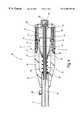
- FIG. 5shows a partial and partly cutaway side view of the grip of the device of FIG. 1, four positions A, B, C, and D of the mouth parts being indicated;
- FIG. 6shows a section along line VI—VI in FIG. 5;
- FIG. 7shows a section along line VII—VII in FIG. 5;
- FIG. 8shows a force/displacement diagram as a function of the rotation angle of the rotatable grip element
- FIG. 9shows a section view, comparable to the section view of FIG. 4, of a second exemplifying embodiment having levers which can swing out laterally.
- FIGS. 1 through 3A surgical grasping and holding forceps, shown in FIGS. 1 through 3, is labeled in its entirety with the reference number 10 .
- Forceps 10has an elongated cylindrical shaft 12 at whose distal end two mouth parts 14 and 16 are arranged. Arranged at the proximal end of shaft 12 is an approximately rod-shaped grip 18 extending longitudinally in the shaft axis.
- a mechanism 20 for moving mouth parts 14 and 16is received in grip 18 , as is evident in particular from the section view of FIG. 4 .
- Mechanism 20has a rod-shaped actuation element 22 which passes through shaft 12 and is connected at the distal end via a toggle lever linkage (not shown here) to the two mouth parts 14 and 16 , as is known per se for forceps of this kind.
- actuation element 22extends out slightly beyond the end of grip 18 , and a pusher sleeve 24 is slid over the end region of actuation element 22 .
- Pusher sleeve 24has an end-mounted pusher 26 , and pusher sleeve 24 extends beyond an inner flange 94 in grip 18 in the direction of shaft 12 .
- An adjusting screw 28which is threaded onto threads of actuation element 22 , is arranged in pusher 26 .
- the relative displacement position between pusher sleeve 24 and actuation element 22can be adjusted within a certain range, and made evident, by way of adjusting screw 28 .
- a gate body 34is slid onto actuation element 22 from its distal end until said body has arrived at an annular flange 32 of the pusher sleeve 24 .
- Gate body 34has a conical section 36 which continues proximally into a cylindrical section 38 .
- the outside diameter of cylindrical section 38 of gate body 34is such that it corresponds approximately to the inside diameter of a cylindrical end section of a housing 40 that is immovably joined to shaft 12 .
- the distance between the distal end of cylindrical section 38 and a step 41 on the interior of housing 40is such that the mouth parts can be opened by pressure on pusher 26 and corresponding displacement of actuation element 22 .
- Two radially projecting pins 42 and 43protrude in diametrically opposite fashion from cylindrical section 38 of gate body 34 .
- Pins 42 and 43engage into a gate 44 which is slid over the cylindrical end section of housing 40 .
- a side view of gate 44is shown in FIG. 5 .
- Gate 44has distally an annular flange 46 which sits on a shoulder on the exterior of housing 40 .
- gate 44has a hollow-cylindrical section 48 which is slid onto the exterior of the cylindrical end section of housing 40 .
- Two grooves 50 , 51are cut in diametrically opposing fashion into hollow-cylindrical section 48 of gate 44 .
- Pins 42 and 43 of gate body 34engage into grooves 50 and 51 , respectively.
- Corresponding cutoutsare present for this purpose in housing 40 .
- Groove 50(and, in correspondingly rotationally symmetrical fashion, groove 51 ) has an axial section 52 into which pin 42 of gate body 34 engages.
- Axial section 52opens toward annular flange 46 of gate 44 .
- transition from axial section 52 into circumferential section 54 rising in the proximal directionis configured so as to accommodate adjustability via adjusting screw 28 and the resulting change in the relative displacement position between pusher sleeve 24 and actuation element 22 , as well as differences in the resistance force exhibited by objects held by the mouth parts, which can result in great differences in the partial opening angles of the mouth parts upon application of the pre-holding force.
- a closure cap 60is slid snuggly over gate 44 in order to close off the grooves with a correspondingly ergonomic configuration, as is evident from FIGS. 1 through 4.
- Closure cap 44thus sits in nonpositively fixed fashion on gate 60 , and the assembly made up of closure cap 60 and gate 44 forms a rotatable section 62 of grip 18 .
- a lock 64is provided in housing 40 .
- Lock 64has an axially extending stud 66 which is acted upon by the force of a spring 68 in such a way that it moves gate 44 in the proximal direction. Stud 66 is joined to a slide element 70 which is arranged in a recess 72 in housing 40 . The contour of slide element 70 is such that it does not project beyond the housing, but nevertheless can be grasped and actuated, i.e. displaced, from the outside with a finger. Lock 64 is arranged so that the tip of stud 66 is oriented toward the annular end surface of annular flange 46 .
- a blind hole 74is provided in annular flange 46 , into which stud 66 can travel. This occurs in the rotational position shown in FIG. 5, which corresponds to a final closed position D, as will be explained in more detail later.
- a circumferentially arranged interlock 76which prevents gate 44 from sliding axially off housing 40 , is arranged in the region of annular flange 46 of gate 44 .
- Interlock 76has a rocker 78 , one of whose ends is equipped with a locking peg 80 .
- Locking peg 80engages into a circumferential recess on the exterior of housing 40 ; it thus allows relative rotation between gate 44 and housing 40 about the shaft axis, but inhibits any axial sliding.
- the length of the circumferential openingis such that the final closed position is reached upon rotation of grip 18 .
- Rocker 78has a pushbutton 82 on the side opposite locking peg 80 . Pressure on pushbutton 82 causes locking peg 80 to snap out, so that gate 44 can be pulled off proximally from housing 40 , for example for cleaning and sterilization purposes.
- Forceps 10is handled so that grip 18 is grasped with one hand, and one thumb is used to press onto pusher 26 , as shown in FIG. 1 by an arrow 27 .
- the rotatable part of grip 18is in the position in which the device is “opened,” i.e. pin 42 is located in axial section 52 of groove 50 .
- Actuation element 22is thereby displaced against the force of spring 92 toward the distal end, and mouth parts 14 and 16 are maximally spread, for example to an opening angle of approx. 50 degrees.
- spherical sponge 90Once spherical sponge 90 has been introduced between mouth parts 14 and 16 , pusher 26 is released and the preloaded spring 92 displaces the assembly made up of actuation element 22 and gate body 34 toward the proximal end, thus causing mouth parts 14 and 16 to close somewhat until they have reached the position labeled B in FIG. 5 . In this partially closed position, spherical sponge 90 is caught between mouth parts 14 and 16 and is held with a pre-holding force due to the force of spring 92 .
- Pin 42has now moved along axial section 52 of groove 50 into the position indicated in FIG. 5 by the arrow proceeding from position B. In this position, pin 42 is also located at the beginning of rising section 54 of groove 50 .
- the transition region from axial section 52 into the circumferential and axially rising section 54 of groove 50is configured so that a change in the relative displacement position between pusher sleeve 24 and actuation element 22 , and a difference in the resistance presented by objects to be held in the mouth parts, which can result in different partial opening angles of the mouth parts upon application of the pre-holding force, can be accommodated.
- pin 42moves first along rising section 54 of groove 50 and then into the downward-sloping end section 56 until stop 58 is reached.
- the letter Cdesignates the intermediate position in which pin 42 has just reached the transition from rising section 54 to the downward-sloping end section 56 .
- actuation element 22 together with gate body 34is moved maximally in the proximal direction against the resistance offered by the object held by the mouth parts. This assembly then moves slightly back again toward the distal end until it then reaches the final closed position D.
- gate 44The coacting parts—gate 44 , gate body 34 , and actuation element 22 joined to the latter—form an device 30 which operates as a rigid linkage to move mouth parts 14 and 16 positively into the defined final closed position D.
- mouth parts 14 and 16each have the cross-sectional profile of a semi-oval 88 , 89 .
- the overall result, for the closed mouth parts in the final closed position D,is an approximately oval outer contour which allows dissection with the closed mouth parts 14 and 16 .
- gate 44is rotated so that its blind hole 74 comes to rest in front of stud 66 of lock 64 , so that spring 68 now slides stud 66 into the blind hole and closes lock 64 .
- Forceps 10can now be introduced into a body, for example through a trocar, and corresponding dissection operations can be performed.
- stud 66is displaced by way of slide element 70 against the force of spring 68 , and lock 64 is released.
- Rotatable section 62is then rotated in a direction opposite to the one described previously, so that mouth parts 14 and 16 are partially opened again, i.e. have once again reached the position shown in FIG. 2 .
- Pressureis then exerted again on pusher 26 in order to spread mouth parts 14 and 16 to their maximum extent, so that spherical sponge 90 can be removed and, for example, replaced by another one.
- FIG. 8depicts a diagram which shows the force f and linear stroke H of actuation element 22 as a function of the rotation angle of rotatable section 62 of grip 18 .
- the very small displacements of actuation element 22result in a relatively flat curve with a corresponding torque, i.e. the rotary movement that occurs is acted upon by a relatively uniform force, and is inhibited once the stop is reached.
- the displacement of slide element 70 of lock 64indicates to the operator that rotatable section 62 has been rotated into the correct position, and that mouth parts 14 and 16 are now being acted upon by the desired holding force.
- Application of additional force onto rotatable section 62causes no further movement of mouth parts 14 and 16 .
- the applied forcesare then diverted onto grip 18 .
- the positioncorresponds to a “closed” or “ON” position. These positions can be indicated on the grip, for example, by the words “ON” and “OFF”.
- reference numbers 95 and 96designate flushing orifices in flange 94 and in conical section 36 of the gate body, so that the entire interior can be flushed for cleaning purposes.
- a laterally protruding fitting 98through which a flushing or cleaning liquid can be delivered and passed through the grip via cleaning openings 95 and 96 , is provided for this purpose on shaft 12 .
- FIG. 9shows a forceps 100 only in the region of its grip 104 .
- Forceps 100also has at its distal end two mouth parts which are mounted on a shaft 102 .
- An actuation element 122 extending through shaft 102is equipped, as described above, with a pusher sleeve 120 at the end.
- a spring 124extends between an internally projecting flange 128 of a housing 106 and a corresponding outer annular flange 126 on pusher sleeve 120 .
- levers 111 , 112are arranged, diametrically opposite one another, in two longitudinal grooves 138 and 140 cut out of housing 106 .
- Levers 111 and 112are pivotable about axes 113 and 114 , respectively.
- Two short lever arms of each lever 111 , 112 beyond axes 113 , 114are configured respectively as knobs 115 and 116 , which engage into corresponding recesses 117 and 118 on the exterior of pusher sleeve 120 .
- the two levers 111 , 112are shown with solid lines in their swung-in or flush position; this position corresponds to the final closed position D of the mouth parts as described above.
- a step 129 , 130onto which a lock 107 in the form of a slide bushing 108 can be slid, as shown in the sectioned view of FIG. 9 .
- Slide bushing 108is equipped with a radially inwardly projecting peg 109 which is received in a corresponding opening 110 on the exterior of housing 106 . Opening 110 limits the axial displacement travel of slide bushing 108 .
- slide bushing 108is additionally secured by a ball catch 132 .
- a spring 134which rests radially outwardly on a ball 133 is received in a blind hole located approximately diametrically opposite peg 109 . Spring 134 pushes ball 133 into a corresponding recess 136 on the interior of slide bushing 108 .
- slide bushing 108When slide bushing 108 is displaced distally, overcoming the inhibiting force of ball catch 132 , slide bushing 108 moves out of steps 129 , 130 of levers 111 , 112 , and the latter can be swung outward about their corresponding axes 113 , 114 .
- FIG. 9A position of this kind is indicated in FIG. 9 by the dashed lines.
- knobs 115 , 116have also displaced pusher sleeve 120 in the distal direction, thereby opening the mouth parts.
- pusher sleeve 120By further pressure on pusher sleeve 120 the mouth parts can, if applicable, be opened even further, thus also spreading levers 111 , 112 farther apart.
- the assembly made up of levers 111 , 112 and pusher sleeve 120thus forms device 105 , operating as a rigid linkage, for moving the mouth parts in positive and defined fashion into the final closed position D described above.
- a base 144 , 145 of each longitudinal groove 138 , 140constitutes a stop beyond which levers 111 , 112 cannot be displaced farther inward.
- FIG. 9is also correspondingly provided with flushing orifices (not shown here), so that here again the interior can be flushed with a cleaning liquid through a lateral fitting (not designated in detail here).
Landscapes
- Health & Medical Sciences (AREA)
- Surgery (AREA)
- Life Sciences & Earth Sciences (AREA)
- Biomedical Technology (AREA)
- Nuclear Medicine, Radiotherapy & Molecular Imaging (AREA)
- Engineering & Computer Science (AREA)
- Heart & Thoracic Surgery (AREA)
- Medical Informatics (AREA)
- Molecular Biology (AREA)
- Animal Behavior & Ethology (AREA)
- General Health & Medical Sciences (AREA)
- Public Health (AREA)
- Veterinary Medicine (AREA)
- Ophthalmology & Optometry (AREA)
- Surgical Instruments (AREA)
Abstract
Description
Claims (23)
Priority Applications (1)
| Application Number | Priority Date | Filing Date | Title |
|---|---|---|---|
| US09/938,702US6635071B2 (en) | 1997-07-22 | 2001-08-24 | Surgical grasping and holding forceps |
Applications Claiming Priority (2)
| Application Number | Priority Date | Filing Date | Title |
|---|---|---|---|
| DE19731454ADE19731454A1 (en) | 1997-07-22 | 1997-07-22 | Surgical grasping and holding forceps |
| PCT/EP1998/004576WO1999004702A1 (en) | 1997-07-22 | 1998-07-21 | Surgical grasping and holding pliers |
Related Parent Applications (1)
| Application Number | Title | Priority Date | Filing Date |
|---|---|---|---|
| PCT/EP1998/004576ContinuationWO1999004702A1 (en) | 1997-07-22 | 1998-07-21 | Surgical grasping and holding pliers |
Related Child Applications (1)
| Application Number | Title | Priority Date | Filing Date |
|---|---|---|---|
| US09/938,702DivisionUS6635071B2 (en) | 1997-07-22 | 2001-08-24 | Surgical grasping and holding forceps |
Publications (1)
| Publication Number | Publication Date |
|---|---|
| US6280458B1true US6280458B1 (en) | 2001-08-28 |
Family
ID=26038476
Family Applications (2)
| Application Number | Title | Priority Date | Filing Date |
|---|---|---|---|
| US09/274,419Expired - LifetimeUS6280458B1 (en) | 1997-07-22 | 1999-03-22 | Surgical grasping and holding forceps |
| US09/938,702Expired - LifetimeUS6635071B2 (en) | 1997-07-22 | 2001-08-24 | Surgical grasping and holding forceps |
Family Applications After (1)
| Application Number | Title | Priority Date | Filing Date |
|---|---|---|---|
| US09/938,702Expired - LifetimeUS6635071B2 (en) | 1997-07-22 | 2001-08-24 | Surgical grasping and holding forceps |
Country Status (1)
| Country | Link |
|---|---|
| US (2) | US6280458B1 (en) |
Cited By (174)
| Publication number | Priority date | Publication date | Assignee | Title |
|---|---|---|---|---|
| US20020188294A1 (en)* | 2001-04-06 | 2002-12-12 | Couture Gary M. | Vessel sealer and divider |
| US20030018332A1 (en)* | 2001-06-20 | 2003-01-23 | Schmaltz Dale Francis | Bipolar electrosurgical instrument with replaceable electrodes |
| US20030040802A1 (en)* | 2001-07-16 | 2003-02-27 | Errico Joseph P. | Artificial intervertebral disc having limited rotation using a captured ball and socket joint with a solid ball and compression locking post |
| US20030069586A1 (en)* | 2001-07-16 | 2003-04-10 | Errico Joseph P. | Instrumentation and methods for use in implanting an artificial intervertebral disc |
| US20030078590A1 (en)* | 2001-07-16 | 2003-04-24 | Errico Joseph P. | Static trials and related instruments and methods for use in implanting an artificial intervertebral disc |
| US6594552B1 (en)* | 1999-04-07 | 2003-07-15 | Intuitive Surgical, Inc. | Grip strength with tactile feedback for robotic surgery |
| US20030181910A1 (en)* | 1998-10-23 | 2003-09-25 | Dycus Sean T. | Bipolar electrosurgical forceps with non-conductive stop members |
| US20040082952A1 (en)* | 2001-04-06 | 2004-04-29 | Dycus Sean T. | Vessel sealer and divider |
| US20040147922A1 (en)* | 2002-12-10 | 2004-07-29 | Keppel David S. | Electrosurgical electrode having a non-conductive porous ceramic coating |
| US20040162559A1 (en)* | 2003-02-14 | 2004-08-19 | Arramon Yves P. | Bone access system |
| US20040176762A1 (en)* | 1997-11-12 | 2004-09-09 | Lawes Kate R. | Electrosurgical instrument reducing flashover |
| US20040199204A1 (en)* | 2003-02-14 | 2004-10-07 | Voegele James W. | Multifunctional surgical instrument |
| US20040236325A1 (en)* | 2001-04-06 | 2004-11-25 | Tetzlaff Philip M. | Vesel sealing forceps with disposable electrodes |
| US20040254573A1 (en)* | 2003-06-13 | 2004-12-16 | Dycus Sean T. | Vessel sealer and divider for use with small trocars and cannulas |
| US20040250419A1 (en)* | 2003-06-13 | 2004-12-16 | Sremcich Paul S. | Method of manufacturing jaw assembly for vessel sealer and divider |
| US20050187632A1 (en)* | 2004-02-20 | 2005-08-25 | Rafail Zubok | Artificial intervertebral disc having a bored semispherical bearing with a compression locking post and retaining caps |
| US20050246022A1 (en)* | 2004-02-20 | 2005-11-03 | Rafail Zubok | Artificial intervertebral disc having a universal joint |
| US20050251110A1 (en)* | 2004-05-04 | 2005-11-10 | Intuitive Surgical, Inc. | Tool grip calibration for robotic surgery |
| USD525361S1 (en) | 2004-10-06 | 2006-07-18 | Sherwood Services Ag | Hemostat style elongated dissecting and dividing instrument |
| US7090673B2 (en) | 2001-04-06 | 2006-08-15 | Sherwood Services Ag | Vessel sealer and divider |
| US20060195140A1 (en)* | 2004-03-26 | 2006-08-31 | Olympus Corporation | Surgical gripper |
| US7101373B2 (en) | 2001-04-06 | 2006-09-05 | Sherwood Services Ag | Vessel sealer and divider |
| US7103947B2 (en) | 2001-04-06 | 2006-09-12 | Sherwood Services Ag | Molded insulating hinge for bipolar instruments |
| US7118587B2 (en) | 2001-04-06 | 2006-10-10 | Sherwood Services Ag | Vessel sealer and divider |
| US7118599B2 (en) | 2001-07-16 | 2006-10-10 | Spinecore, Inc. | Artificial intervertebral disc |
| USD531311S1 (en) | 2004-10-06 | 2006-10-31 | Sherwood Services Ag | Pistol grip style elongated dissecting and dividing instrument |
| US7131970B2 (en) | 2003-11-19 | 2006-11-07 | Sherwood Services Ag | Open vessel sealing instrument with cutting mechanism |
| US20060259070A1 (en)* | 2005-04-29 | 2006-11-16 | Steve Livneh | Forceps for performing endoscopic or arthroscopic surgery |
| US7137988B2 (en)* | 2001-03-03 | 2006-11-21 | Frye Darrin L | Needle driver |
| US7147638B2 (en) | 2003-05-01 | 2006-12-12 | Sherwood Services Ag | Electrosurgical instrument which reduces thermal damage to adjacent tissue |
| USD533942S1 (en) | 2004-06-30 | 2006-12-19 | Sherwood Services Ag | Open vessel sealer with mechanical cutter |
| US7150749B2 (en) | 2003-06-13 | 2006-12-19 | Sherwood Services Ag | Vessel sealer and divider having elongated knife stroke and safety cutting mechanism |
| US7160327B2 (en) | 2001-07-16 | 2007-01-09 | Spinecore, Inc. | Axially compressible artificial intervertebral disc having limited rotation using a captured ball and socket joint with a solid ball and compression locking post |
| US7160299B2 (en) | 2003-05-01 | 2007-01-09 | Sherwood Services Ag | Method of fusing biomaterials with radiofrequency energy |
| USD535027S1 (en) | 2004-10-06 | 2007-01-09 | Sherwood Services Ag | Low profile vessel sealing and cutting mechanism |
| US7160298B2 (en) | 1997-11-12 | 2007-01-09 | Sherwood Services Ag | Electrosurgical instrument which reduces effects to adjacent tissue structures |
| US7179258B2 (en) | 1997-11-12 | 2007-02-20 | Sherwood Services Ag | Bipolar electrosurgical instrument for sealing vessels |
| US7195631B2 (en) | 2004-09-09 | 2007-03-27 | Sherwood Services Ag | Forceps with spring loaded end effector assembly |
| USD541418S1 (en) | 2004-10-06 | 2007-04-24 | Sherwood Services Ag | Lung sealing device |
| US7207990B2 (en) | 1997-11-14 | 2007-04-24 | Sherwood Services Ag | Laparoscopic bipolar electrosurgical instrument |
| USD541938S1 (en) | 2004-04-09 | 2007-05-01 | Sherwood Services Ag | Open vessel sealer with mechanical cutter |
| US7232440B2 (en) | 2003-11-17 | 2007-06-19 | Sherwood Services Ag | Bipolar forceps having monopolar extension |
| US7235081B2 (en) | 2001-07-16 | 2007-06-26 | Spinecore, Inc. | Wedge plate inserter/impactor and related methods for use in implanting an artificial intervertebral disc |
| US7241296B2 (en) | 1997-11-12 | 2007-07-10 | Sherwood Services Ag | Bipolar electrosurgical instrument for sealing vessels |
| US7252667B2 (en) | 2003-11-19 | 2007-08-07 | Sherwood Services Ag | Open vessel sealing instrument with cutting mechanism and distal lockout |
| US7255697B2 (en) | 2001-04-06 | 2007-08-14 | Sherwood Services Ag | Vessel sealer and divider |
| US7267677B2 (en) | 1998-10-23 | 2007-09-11 | Sherwood Services Ag | Vessel sealing instrument |
| US7270660B2 (en) | 1997-09-09 | 2007-09-18 | Sherwood Services Ag | Apparatus and method for sealing and cutting tissue |
| US7270664B2 (en) | 2002-10-04 | 2007-09-18 | Sherwood Services Ag | Vessel sealing instrument with electrical cutting mechanism |
| US7276068B2 (en) | 2002-10-04 | 2007-10-02 | Sherwood Services Ag | Vessel sealing instrument with electrical cutting mechanism |
| US20070265618A1 (en)* | 2006-05-15 | 2007-11-15 | Long Gary L | Bipolar probe with an injection needle |
| US20070270798A1 (en)* | 2006-05-19 | 2007-11-22 | Ifung Lu | Bipolar forceps |
| US20070299469A1 (en)* | 2006-06-26 | 2007-12-27 | David Carpenter | Surgical device |
| USD564662S1 (en) | 2004-10-13 | 2008-03-18 | Sherwood Services Ag | Hourglass-shaped knife for electrosurgical forceps |
| USD567943S1 (en) | 2004-10-08 | 2008-04-29 | Sherwood Services Ag | Over-ratchet safety for a vessel sealing instrument |
| US7367976B2 (en) | 2003-11-17 | 2008-05-06 | Sherwood Services Ag | Bipolar forceps having monopolar extension |
| US7377920B2 (en) | 1997-11-14 | 2008-05-27 | Sherwood Services Ag | Laparoscopic bipolar electrosurgical instrument |
| US7384421B2 (en) | 2004-10-06 | 2008-06-10 | Sherwood Services Ag | Slide-activated cutting assembly |
| USD575401S1 (en) | 2007-06-12 | 2008-08-19 | Tyco Healthcare Group Lp | Vessel sealer |
| USD575395S1 (en) | 2007-02-15 | 2008-08-19 | Tyco Healthcare Group Lp | Hemostat style elongated dissecting and dividing instrument |
| US7435249B2 (en) | 1997-11-12 | 2008-10-14 | Covidien Ag | Electrosurgical instruments which reduces collateral damage to adjacent tissue |
| US7442193B2 (en) | 2003-11-20 | 2008-10-28 | Covidien Ag | Electrically conductive/insulative over-shoe for tissue fusion |
| US7473253B2 (en) | 2001-04-06 | 2009-01-06 | Covidien Ag | Vessel sealer and divider with non-conductive stop members |
| US7491201B2 (en) | 2003-05-15 | 2009-02-17 | Covidien Ag | Tissue sealer with non-conductive variable stop members and method of sealing tissue |
| US7491202B2 (en) | 2005-03-31 | 2009-02-17 | Covidien Ag | Electrosurgical forceps with slow closure sealing plates and method of sealing tissue |
| US7500975B2 (en) | 2003-11-19 | 2009-03-10 | Covidien Ag | Spring loaded reciprocating tissue cutting mechanism in a forceps-style electrosurgical instrument |
| US7510556B2 (en) | 1998-10-23 | 2009-03-31 | Coviden Ag | Vessel sealing instrument |
| US7540872B2 (en) | 2004-09-21 | 2009-06-02 | Covidien Ag | Articulating bipolar electrosurgical instrument |
| US7553312B2 (en) | 1998-10-23 | 2009-06-30 | Covidien Ag | Vessel sealing instrument |
| US7582087B2 (en) | 1998-10-23 | 2009-09-01 | Covidien Ag | Vessel sealing instrument |
| US7594916B2 (en) | 2005-11-22 | 2009-09-29 | Covidien Ag | Electrosurgical forceps with energy based tissue division |
| US7597693B2 (en) | 2003-06-13 | 2009-10-06 | Covidien Ag | Vessel sealer and divider for use with small trocars and cannulas |
| US7628791B2 (en) | 2005-08-19 | 2009-12-08 | Covidien Ag | Single action tissue sealer |
| US7628792B2 (en) | 2004-10-08 | 2009-12-08 | Covidien Ag | Bilateral foot jaws |
| US7641653B2 (en) | 2006-05-04 | 2010-01-05 | Covidien Ag | Open vessel sealing forceps disposable handswitch |
| US7686804B2 (en) | 2005-01-14 | 2010-03-30 | Covidien Ag | Vessel sealer and divider with rotating sealer and cutter |
| US7686827B2 (en) | 2004-10-21 | 2010-03-30 | Covidien Ag | Magnetic closure mechanism for hemostat |
| US7722607B2 (en) | 2005-09-30 | 2010-05-25 | Covidien Ag | In-line vessel sealer and divider |
| US7744615B2 (en) | 2006-07-18 | 2010-06-29 | Covidien Ag | Apparatus and method for transecting tissue on a bipolar vessel sealing instrument |
| US7762960B2 (en) | 2005-05-13 | 2010-07-27 | Boston Scientific Scimed, Inc. | Biopsy forceps assemblies |
| US7766910B2 (en) | 2006-01-24 | 2010-08-03 | Tyco Healthcare Group Lp | Vessel sealer and divider for large tissue structures |
| US7771477B2 (en) | 2001-10-01 | 2010-08-10 | Spinecore, Inc. | Intervertebral spacer device utilizing a belleville washer having radially spaced concentric grooves |
| US7776036B2 (en) | 2003-03-13 | 2010-08-17 | Covidien Ag | Bipolar concentric electrode assembly for soft tissue fusion |
| US7776037B2 (en) | 2006-07-07 | 2010-08-17 | Covidien Ag | System and method for controlling electrode gap during tissue sealing |
| US7789878B2 (en) | 2005-09-30 | 2010-09-07 | Covidien Ag | In-line vessel sealer and divider |
| US7799026B2 (en) | 2002-11-14 | 2010-09-21 | Covidien Ag | Compressible jaw configuration with bipolar RF output electrodes for soft tissue fusion |
| US7811283B2 (en) | 2003-11-19 | 2010-10-12 | Covidien Ag | Open vessel sealing instrument with hourglass cutting mechanism and over-ratchet safety |
| US7819872B2 (en) | 2005-09-30 | 2010-10-26 | Covidien Ag | Flexible endoscopic catheter with ligasure |
| US7837685B2 (en) | 2005-07-13 | 2010-11-23 | Covidien Ag | Switch mechanisms for safe activation of energy on an electrosurgical instrument |
| US7846161B2 (en) | 2005-09-30 | 2010-12-07 | Covidien Ag | Insulating boot for electrosurgical forceps |
| US7846158B2 (en) | 2006-05-05 | 2010-12-07 | Covidien Ag | Apparatus and method for electrode thermosurgery |
| US7857812B2 (en) | 2003-06-13 | 2010-12-28 | Covidien Ag | Vessel sealer and divider having elongated knife stroke and safety for cutting mechanism |
| US7879035B2 (en) | 2005-09-30 | 2011-02-01 | Covidien Ag | Insulating boot for electrosurgical forceps |
| US7877853B2 (en) | 2007-09-20 | 2011-02-01 | Tyco Healthcare Group Lp | Method of manufacturing end effector assembly for sealing tissue |
| US7877852B2 (en) | 2007-09-20 | 2011-02-01 | Tyco Healthcare Group Lp | Method of manufacturing an end effector assembly for sealing tissue |
| US7887535B2 (en) | 1999-10-18 | 2011-02-15 | Covidien Ag | Vessel sealing wave jaw |
| US7909823B2 (en) | 2005-01-14 | 2011-03-22 | Covidien Ag | Open vessel sealing instrument |
| US7922953B2 (en) | 2005-09-30 | 2011-04-12 | Covidien Ag | Method for manufacturing an end effector assembly |
| US7931649B2 (en) | 2002-10-04 | 2011-04-26 | Tyco Healthcare Group Lp | Vessel sealing instrument with electrical cutting mechanism |
| US7951149B2 (en) | 2006-10-17 | 2011-05-31 | Tyco Healthcare Group Lp | Ablative material for use with tissue treatment device |
| US7955332B2 (en) | 2004-10-08 | 2011-06-07 | Covidien Ag | Mechanism for dividing tissue in a hemostat-style instrument |
| US8016827B2 (en) | 2008-10-09 | 2011-09-13 | Tyco Healthcare Group Lp | Apparatus, system, and method for performing an electrosurgical procedure |
| US8029568B2 (en) | 2001-10-18 | 2011-10-04 | Spinecore, Inc. | Intervertebral spacer device having a slotted partial circular domed arch strip spring |
| USD649249S1 (en) | 2007-02-15 | 2011-11-22 | Tyco Healthcare Group Lp | End effectors of an elongated dissecting and dividing instrument |
| US8070746B2 (en) | 2006-10-03 | 2011-12-06 | Tyco Healthcare Group Lp | Radiofrequency fusion of cardiac tissue |
| US8109979B2 (en) | 2003-03-06 | 2012-02-07 | Spinecore, Inc. | Instrumentation and methods for use in implanting a cervical disc replacement device |
| US8128624B2 (en) | 2003-05-01 | 2012-03-06 | Covidien Ag | Electrosurgical instrument that directs energy delivery and protects adjacent tissue |
| US8142473B2 (en) | 2008-10-03 | 2012-03-27 | Tyco Healthcare Group Lp | Method of transferring rotational motion in an articulating surgical instrument |
| US8162973B2 (en) | 2008-08-15 | 2012-04-24 | Tyco Healthcare Group Lp | Method of transferring pressure in an articulating surgical instrument |
| US8197479B2 (en) | 2008-12-10 | 2012-06-12 | Tyco Healthcare Group Lp | Vessel sealer and divider |
| US8211105B2 (en) | 1997-11-12 | 2012-07-03 | Covidien Ag | Electrosurgical instrument which reduces collateral damage to adjacent tissue |
| US8221416B2 (en) | 2007-09-28 | 2012-07-17 | Tyco Healthcare Group Lp | Insulating boot for electrosurgical forceps with thermoplastic clevis |
| US8235993B2 (en) | 2007-09-28 | 2012-08-07 | Tyco Healthcare Group Lp | Insulating boot for electrosurgical forceps with exohinged structure |
| US8235992B2 (en) | 2007-09-28 | 2012-08-07 | Tyco Healthcare Group Lp | Insulating boot with mechanical reinforcement for electrosurgical forceps |
| US8236025B2 (en) | 2007-09-28 | 2012-08-07 | Tyco Healthcare Group Lp | Silicone insulated electrosurgical forceps |
| US8241283B2 (en) | 2007-09-28 | 2012-08-14 | Tyco Healthcare Group Lp | Dual durometer insulating boot for electrosurgical forceps |
| US8241282B2 (en) | 2006-01-24 | 2012-08-14 | Tyco Healthcare Group Lp | Vessel sealing cutting assemblies |
| US8251996B2 (en) | 2007-09-28 | 2012-08-28 | Tyco Healthcare Group Lp | Insulating sheath for electrosurgical forceps |
| US8257387B2 (en) | 2008-08-15 | 2012-09-04 | Tyco Healthcare Group Lp | Method of transferring pressure in an articulating surgical instrument |
| US8267935B2 (en) | 2007-04-04 | 2012-09-18 | Tyco Healthcare Group Lp | Electrosurgical instrument reducing current densities at an insulator conductor junction |
| US8267936B2 (en) | 2007-09-28 | 2012-09-18 | Tyco Healthcare Group Lp | Insulating mechanically-interfaced adhesive for electrosurgical forceps |
| US8277507B2 (en) | 2002-04-12 | 2012-10-02 | Spinecore, Inc. | Spacerless artificial disc replacements |
| US8298232B2 (en) | 2006-01-24 | 2012-10-30 | Tyco Healthcare Group Lp | Endoscopic vessel sealer and divider for large tissue structures |
| US8303582B2 (en) | 2008-09-15 | 2012-11-06 | Tyco Healthcare Group Lp | Electrosurgical instrument having a coated electrode utilizing an atomic layer deposition technique |
| US8317787B2 (en) | 2008-08-28 | 2012-11-27 | Covidien Lp | Tissue fusion jaw angle improvement |
| US8348948B2 (en) | 2004-03-02 | 2013-01-08 | Covidien Ag | Vessel sealing system using capacitive RF dielectric heating |
| US8361071B2 (en) | 1999-10-22 | 2013-01-29 | Covidien Ag | Vessel sealing forceps with disposable electrodes |
| USD680220S1 (en) | 2012-01-12 | 2013-04-16 | Coviden IP | Slider handle for laparoscopic device |
| US8454602B2 (en) | 2009-05-07 | 2013-06-04 | Covidien Lp | Apparatus, system, and method for performing an electrosurgical procedure |
| US8469957B2 (en) | 2008-10-07 | 2013-06-25 | Covidien Lp | Apparatus, system, and method for performing an electrosurgical procedure |
| US8469956B2 (en) | 2008-07-21 | 2013-06-25 | Covidien Lp | Variable resistor jaw |
| US8470041B2 (en) | 2002-04-12 | 2013-06-25 | Spinecore, Inc. | Two-component artificial disc replacements |
| US8486107B2 (en) | 2008-10-20 | 2013-07-16 | Covidien Lp | Method of sealing tissue using radiofrequency energy |
| WO2013112038A1 (en)* | 2012-01-10 | 2013-08-01 | Guzman Sanchez Arnoldo | Syringe-type surgical clamp |
| US8523898B2 (en) | 2009-07-08 | 2013-09-03 | Covidien Lp | Endoscopic electrosurgical jaws with offset knife |
| US8535312B2 (en) | 2008-09-25 | 2013-09-17 | Covidien Lp | Apparatus, system and method for performing an electrosurgical procedure |
| US8591506B2 (en) | 1998-10-23 | 2013-11-26 | Covidien Ag | Vessel sealing system |
| US8597297B2 (en) | 2006-08-29 | 2013-12-03 | Covidien Ag | Vessel sealing instrument with multiple electrode configurations |
| US8623276B2 (en) | 2008-02-15 | 2014-01-07 | Covidien Lp | Method and system for sterilizing an electrosurgical instrument |
| US8636761B2 (en) | 2008-10-09 | 2014-01-28 | Covidien Lp | Apparatus, system, and method for performing an endoscopic electrosurgical procedure |
| US8734443B2 (en) | 2006-01-24 | 2014-05-27 | Covidien Lp | Vessel sealer and divider for large tissue structures |
| US8764748B2 (en) | 2008-02-06 | 2014-07-01 | Covidien Lp | End effector assembly for electrosurgical device and method for making the same |
| US8784417B2 (en) | 2008-08-28 | 2014-07-22 | Covidien Lp | Tissue fusion jaw angle improvement |
| US8795274B2 (en) | 2008-08-28 | 2014-08-05 | Covidien Lp | Tissue fusion jaw angle improvement |
| US8852228B2 (en) | 2009-01-13 | 2014-10-07 | Covidien Lp | Apparatus, system, and method for performing an electrosurgical procedure |
| US8882766B2 (en) | 2006-01-24 | 2014-11-11 | Covidien Ag | Method and system for controlling delivery of energy to divide tissue |
| US8898888B2 (en) | 2009-09-28 | 2014-12-02 | Covidien Lp | System for manufacturing electrosurgical seal plates |
| US8968314B2 (en) | 2008-09-25 | 2015-03-03 | Covidien Lp | Apparatus, system and method for performing an electrosurgical procedure |
| US9023043B2 (en) | 2007-09-28 | 2015-05-05 | Covidien Lp | Insulating mechanically-interfaced boot and jaws for electrosurgical forceps |
| US9028493B2 (en) | 2009-09-18 | 2015-05-12 | Covidien Lp | In vivo attachable and detachable end effector assembly and laparoscopic surgical instrument and methods therefor |
| US9113940B2 (en) | 2011-01-14 | 2015-08-25 | Covidien Lp | Trigger lockout and kickback mechanism for surgical instruments |
| US9168073B2 (en) | 2013-03-15 | 2015-10-27 | DePuy Synthes Products, Inc. | Spinous process fixator |
| US9375254B2 (en) | 2008-09-25 | 2016-06-28 | Covidien Lp | Seal and separate algorithm |
| US9603652B2 (en) | 2008-08-21 | 2017-03-28 | Covidien Lp | Electrosurgical instrument including a sensor |
| US9848938B2 (en) | 2003-11-13 | 2017-12-26 | Covidien Ag | Compressible jaw configuration with bipolar RF output electrodes for soft tissue fusion |
| US9907579B2 (en) | 2008-08-13 | 2018-03-06 | DePuy Synthes Products, Inc. | Interspinous spacer assembly |
| US9987078B2 (en) | 2015-07-22 | 2018-06-05 | Covidien Lp | Surgical forceps |
| US10213250B2 (en) | 2015-11-05 | 2019-02-26 | Covidien Lp | Deployment and safety mechanisms for surgical instruments |
| US10231777B2 (en) | 2014-08-26 | 2019-03-19 | Covidien Lp | Methods of manufacturing jaw members of an end-effector assembly for a surgical instrument |
| EP2967613B1 (en)* | 2013-03-11 | 2020-04-22 | Boston Scientific Scimed, Inc. | Medical device handles |
| US10631918B2 (en) | 2015-08-14 | 2020-04-28 | Covidien Lp | Energizable surgical attachment for a mechanical clamp |
| US10646267B2 (en) | 2013-08-07 | 2020-05-12 | Covidien LLP | Surgical forceps |
| US10820949B2 (en) | 1999-04-07 | 2020-11-03 | Intuitive Surgical Operations, Inc. | Medical robotic system with dynamically adjustable slave manipulator characteristics |
| US10835309B1 (en) | 2002-06-25 | 2020-11-17 | Covidien Ag | Vessel sealer and divider |
| US10856933B2 (en) | 2016-08-02 | 2020-12-08 | Covidien Lp | Surgical instrument housing incorporating a channel and methods of manufacturing the same |
| US10918407B2 (en) | 2016-11-08 | 2021-02-16 | Covidien Lp | Surgical instrument for grasping, treating, and/or dividing tissue |
| US10959745B2 (en) | 2016-12-20 | 2021-03-30 | Jet Med Innovations, LLC | Radiolucent grasping device |
| US10987159B2 (en) | 2015-08-26 | 2021-04-27 | Covidien Lp | Electrosurgical end effector assemblies and electrosurgical forceps configured to reduce thermal spread |
| US11045216B2 (en)* | 2016-10-12 | 2021-06-29 | Olympus Corporation | Rotating mechanism for treatment tools |
| US11090050B2 (en) | 2019-09-03 | 2021-08-17 | Covidien Lp | Trigger mechanisms for surgical instruments and surgical instruments including the same |
| US11166759B2 (en) | 2017-05-16 | 2021-11-09 | Covidien Lp | Surgical forceps |
| USD956973S1 (en) | 2003-06-13 | 2022-07-05 | Covidien Ag | Movable handle for endoscopic vessel sealer and divider |
| US11872138B2 (en) | 2005-09-23 | 2024-01-16 | Ldr Medical | Intervertebral disc prosthesis |
| US11957598B2 (en) | 2004-02-04 | 2024-04-16 | Ldr Medical | Intervertebral disc prosthesis |
Families Citing this family (40)
| Publication number | Priority date | Publication date | Assignee | Title |
|---|---|---|---|---|
| US6952117B2 (en)* | 2002-03-08 | 2005-10-04 | Micron Technology Inc. | Distributed clock generator for semiconductor devices and related method of operating semiconductor devices |
| US20040073254A1 (en)* | 2002-10-08 | 2004-04-15 | Jeffrey Wyman | Suture retriever with in-line actuating handle |
| US8562640B2 (en) | 2007-04-16 | 2013-10-22 | Intuitive Surgical Operations, Inc. | Tool with multi-state ratcheted end effector |
| US8100824B2 (en) | 2003-05-23 | 2012-01-24 | Intuitive Surgical Operations, Inc. | Tool with articulation lock |
| US8182417B2 (en) | 2004-11-24 | 2012-05-22 | Intuitive Surgical Operations, Inc. | Articulating mechanism components and system for easy assembly and disassembly |
| US7090637B2 (en) | 2003-05-23 | 2006-08-15 | Novare Surgical Systems, Inc. | Articulating mechanism for remote manipulation of a surgical or diagnostic tool |
| US7410483B2 (en) | 2003-05-23 | 2008-08-12 | Novare Surgical Systems, Inc. | Hand-actuated device for remote manipulation of a grasping tool |
| US7678117B2 (en) | 2004-06-07 | 2010-03-16 | Novare Surgical Systems, Inc. | Articulating mechanism with flex-hinged links |
| US7828808B2 (en) | 2004-06-07 | 2010-11-09 | Novare Surgical Systems, Inc. | Link systems and articulation mechanisms for remote manipulation of surgical or diagnostic tools |
| US9700334B2 (en) | 2004-11-23 | 2017-07-11 | Intuitive Surgical Operations, Inc. | Articulating mechanisms and link systems with torque transmission in remote manipulation of instruments and tools |
| US7785252B2 (en) | 2004-11-23 | 2010-08-31 | Novare Surgical Systems, Inc. | Articulating sheath for flexible instruments |
| US8048152B2 (en)* | 2005-09-30 | 2011-11-01 | Medtronic, Inc. | Method of implanting an annuloplasty prosthesis |
| US7862554B2 (en) | 2007-04-16 | 2011-01-04 | Intuitive Surgical Operations, Inc. | Articulating tool with improved tension member system |
| US8409244B2 (en) | 2007-04-16 | 2013-04-02 | Intuitive Surgical Operations, Inc. | Tool with end effector force limiter |
| US9561045B2 (en) | 2006-06-13 | 2017-02-07 | Intuitive Surgical Operations, Inc. | Tool with rotation lock |
| US8377044B2 (en) | 2007-03-30 | 2013-02-19 | Ethicon Endo-Surgery, Inc. | Detachable end effectors |
| US8465475B2 (en) | 2008-08-18 | 2013-06-18 | Intuitive Surgical Operations, Inc. | Instrument with multiple articulation locks |
| US20110022078A1 (en) | 2009-07-23 | 2011-01-27 | Cameron Dale Hinman | Articulating mechanism |
| US9295485B2 (en) | 2009-10-09 | 2016-03-29 | Ethicon Endo-Surgery, Inc. | Loader for exchanging end effectors in vivo |
| US20110087265A1 (en)* | 2009-10-09 | 2011-04-14 | Nobis Rudolph H | Laparoscopic instrument with attachable end effector |
| US9186203B2 (en)* | 2009-10-09 | 2015-11-17 | Ethicon Endo-Surgery, Inc. | Method for exchanging end effectors In Vivo |
| EP2485662B1 (en) | 2009-10-09 | 2015-09-09 | Applied Medical Resources Corporation | Single port instruments |
| GB2476461A (en)* | 2009-12-22 | 2011-06-29 | Neosurgical Ltd | Laparoscopic surgical device with jaws biased closed |
| US20120150216A1 (en)* | 2010-12-13 | 2012-06-14 | Hickingbotham Dyson W | Distally Actuated Surgical Instrument |
| WO2012082736A1 (en)* | 2010-12-13 | 2012-06-21 | I-Tech Development Company | Proximally actuated surgical instrument |
| JP5669590B2 (en) | 2011-01-20 | 2015-02-12 | オリンパス株式会社 | Master-slave manipulator and medical master-slave manipulator |
| US9161771B2 (en) | 2011-05-13 | 2015-10-20 | Intuitive Surgical Operations Inc. | Medical instrument with snake wrist structure |
| US9161769B2 (en) | 2012-07-30 | 2015-10-20 | Covidien Lp | Endoscopic instrument |
| US9125681B2 (en) | 2012-09-26 | 2015-09-08 | Ethicon Endo-Surgery, Inc. | Detachable end effector and loader |
| US20140088638A1 (en)* | 2012-09-26 | 2014-03-27 | Ethicon Endo-Surgery, Inc. | Detachable End Effector with Lateral Lock |
| US9398905B2 (en) | 2012-12-13 | 2016-07-26 | Ethicon Endo-Surgery, Llc | Circular needle applier with offset needle and carrier tracks |
| US9451937B2 (en) | 2013-02-27 | 2016-09-27 | Ethicon Endo-Surgery, Llc | Percutaneous instrument with collet locking mechanisms |
| US10342520B2 (en) | 2015-08-26 | 2019-07-09 | Ethicon Llc | Articulating surgical devices and loaders having stabilizing features |
| US10335196B2 (en) | 2015-08-31 | 2019-07-02 | Ethicon Llc | Surgical instrument having a stop guard |
| US10251636B2 (en) | 2015-09-24 | 2019-04-09 | Ethicon Llc | Devices and methods for cleaning a surgical device |
| US10702257B2 (en) | 2015-09-29 | 2020-07-07 | Ethicon Llc | Positioning device for use with surgical instruments |
| US10675009B2 (en) | 2015-11-03 | 2020-06-09 | Ethicon Llc | Multi-head repository for use with a surgical device |
| US10912543B2 (en) | 2015-11-03 | 2021-02-09 | Ethicon Llc | Surgical end effector loading device and trocar integration |
| US10265130B2 (en) | 2015-12-11 | 2019-04-23 | Ethicon Llc | Systems, devices, and methods for coupling end effectors to surgical devices and loading devices |
| CN114504408A (en)* | 2022-02-22 | 2022-05-17 | 常州市康辉医疗器械有限公司 | An orthopaedic cage holding tool |
Citations (3)
| Publication number | Priority date | Publication date | Assignee | Title |
|---|---|---|---|---|
| US5201739A (en)* | 1988-05-17 | 1993-04-13 | Wisap Gesellschaft Fur Wissenschaftlichen Apparatebau Mbh | Medical instrument |
| US5252056A (en)* | 1990-03-16 | 1993-10-12 | Ciba-Geigy Corporation | Contact lens casting mould |
| US5499997A (en)* | 1992-04-10 | 1996-03-19 | Sharpe Endosurgical Corporation | Endoscopic tenaculum surgical instrument |
Family Cites Families (13)
| Publication number | Priority date | Publication date | Assignee | Title |
|---|---|---|---|---|
| US2114695A (en)* | 1937-03-05 | 1938-04-19 | Alfred W Anderson | Forceps |
| US4174715A (en) | 1977-03-28 | 1979-11-20 | Hasson Harrith M | Multi-pronged laparoscopy forceps |
| US5338317A (en) | 1991-05-03 | 1994-08-16 | Vance Products Incorporated | Rotational surgical instrument handle |
| DE9109097U1 (en) | 1991-07-24 | 1991-09-19 | Klemm, Bernd, 7801 Umkirch | Surgical holding forceps, especially needle and/or thread holders |
| CA2075241A1 (en) | 1991-10-03 | 1993-04-04 | Stephen W. Gerry | Handle for manipulating a laparoscopic tool |
| US5211655A (en) | 1992-05-08 | 1993-05-18 | Hasson Harrith M | Multiple use forceps for endoscopy |
| DE4216971C2 (en) | 1992-05-22 | 1995-06-08 | Wolf Gmbh Richard | Pliers for grasping and holding tissue or the like |
| US5308357A (en)* | 1992-08-21 | 1994-05-03 | Microsurge, Inc. | Handle mechanism for manual instruments |
| CA2103507C (en) | 1992-09-23 | 1998-09-15 | David A. Nicholas | Locking mechanism for endoscopic or laparoscopic surgical instruments |
| US5383895A (en) | 1993-02-10 | 1995-01-24 | Unisurge, Inc. | Endoscopic surgical grasper and method |
| US5498256A (en) | 1993-05-28 | 1996-03-12 | Snowden-Pencer, Inc. | Surgical instrument handle |
| ES2111988T3 (en) | 1994-06-21 | 1998-03-16 | Aesculap Ag | SURGICAL INSTRUMENT WITH TUBE-SHAPED STEM. |
| DE19731454A1 (en) | 1997-07-22 | 1999-03-04 | Storz Karl Gmbh & Co | Surgical grasping and holding forceps |
- 1999
- 1999-03-22USUS09/274,419patent/US6280458B1/ennot_activeExpired - Lifetime
- 2001
- 2001-08-24USUS09/938,702patent/US6635071B2/ennot_activeExpired - Lifetime
Patent Citations (3)
| Publication number | Priority date | Publication date | Assignee | Title |
|---|---|---|---|---|
| US5201739A (en)* | 1988-05-17 | 1993-04-13 | Wisap Gesellschaft Fur Wissenschaftlichen Apparatebau Mbh | Medical instrument |
| US5252056A (en)* | 1990-03-16 | 1993-10-12 | Ciba-Geigy Corporation | Contact lens casting mould |
| US5499997A (en)* | 1992-04-10 | 1996-03-19 | Sharpe Endosurgical Corporation | Endoscopic tenaculum surgical instrument |
Cited By (331)
| Publication number | Priority date | Publication date | Assignee | Title |
|---|---|---|---|---|
| US7270660B2 (en) | 1997-09-09 | 2007-09-18 | Sherwood Services Ag | Apparatus and method for sealing and cutting tissue |
| US7160298B2 (en) | 1997-11-12 | 2007-01-09 | Sherwood Services Ag | Electrosurgical instrument which reduces effects to adjacent tissue structures |
| US7241296B2 (en) | 1997-11-12 | 2007-07-10 | Sherwood Services Ag | Bipolar electrosurgical instrument for sealing vessels |
| US7963965B2 (en) | 1997-11-12 | 2011-06-21 | Covidien Ag | Bipolar electrosurgical instrument for sealing vessels |
| US7135020B2 (en) | 1997-11-12 | 2006-11-14 | Sherwood Services Ag | Electrosurgical instrument reducing flashover |
| US8298228B2 (en) | 1997-11-12 | 2012-10-30 | Coviden Ag | Electrosurgical instrument which reduces collateral damage to adjacent tissue |
| US8211105B2 (en) | 1997-11-12 | 2012-07-03 | Covidien Ag | Electrosurgical instrument which reduces collateral damage to adjacent tissue |
| US7435249B2 (en) | 1997-11-12 | 2008-10-14 | Covidien Ag | Electrosurgical instruments which reduces collateral damage to adjacent tissue |
| US7179258B2 (en) | 1997-11-12 | 2007-02-20 | Sherwood Services Ag | Bipolar electrosurgical instrument for sealing vessels |
| US20040176762A1 (en)* | 1997-11-12 | 2004-09-09 | Lawes Kate R. | Electrosurgical instrument reducing flashover |
| US7828798B2 (en) | 1997-11-14 | 2010-11-09 | Covidien Ag | Laparoscopic bipolar electrosurgical instrument |
| US7207990B2 (en) | 1997-11-14 | 2007-04-24 | Sherwood Services Ag | Laparoscopic bipolar electrosurgical instrument |
| US7377920B2 (en) | 1997-11-14 | 2008-05-27 | Sherwood Services Ag | Laparoscopic bipolar electrosurgical instrument |
| US7582087B2 (en) | 1998-10-23 | 2009-09-01 | Covidien Ag | Vessel sealing instrument |
| US9107672B2 (en) | 1998-10-23 | 2015-08-18 | Covidien Ag | Vessel sealing forceps with disposable electrodes |
| US7329256B2 (en) | 1998-10-23 | 2008-02-12 | Sherwood Services Ag | Vessel sealing instrument |
| US7553312B2 (en) | 1998-10-23 | 2009-06-30 | Covidien Ag | Vessel sealing instrument |
| US7513898B2 (en) | 1998-10-23 | 2009-04-07 | Covidien Ag | Vessel sealing instrument |
| US8591506B2 (en) | 1998-10-23 | 2013-11-26 | Covidien Ag | Vessel sealing system |
| US7947041B2 (en) | 1998-10-23 | 2011-05-24 | Covidien Ag | Vessel sealing instrument |
| US7887536B2 (en) | 1998-10-23 | 2011-02-15 | Covidien Ag | Vessel sealing instrument |
| US9375270B2 (en) | 1998-10-23 | 2016-06-28 | Covidien Ag | Vessel sealing system |
| US7896878B2 (en) | 1998-10-23 | 2011-03-01 | Coviden Ag | Vessel sealing instrument |
| US9375271B2 (en) | 1998-10-23 | 2016-06-28 | Covidien Ag | Vessel sealing system |
| US7267677B2 (en) | 1998-10-23 | 2007-09-11 | Sherwood Services Ag | Vessel sealing instrument |
| US7510556B2 (en) | 1998-10-23 | 2009-03-31 | Coviden Ag | Vessel sealing instrument |
| US20030181910A1 (en)* | 1998-10-23 | 2003-09-25 | Dycus Sean T. | Bipolar electrosurgical forceps with non-conductive stop members |
| US9463067B2 (en) | 1998-10-23 | 2016-10-11 | Covidien Ag | Vessel sealing system |
| US6594552B1 (en)* | 1999-04-07 | 2003-07-15 | Intuitive Surgical, Inc. | Grip strength with tactile feedback for robotic surgery |
| US10820949B2 (en) | 1999-04-07 | 2020-11-03 | Intuitive Surgical Operations, Inc. | Medical robotic system with dynamically adjustable slave manipulator characteristics |
| US20080154246A1 (en)* | 1999-04-07 | 2008-06-26 | Intuitive Surgical, Inc. | Grip strength with tactile feedback for robotic surgery |
| US7778733B2 (en) | 1999-04-07 | 2010-08-17 | Intuitive Surgical Operations, Inc. | Grip strength with tactile feedback for robotic surgery |
| US7887535B2 (en) | 1999-10-18 | 2011-02-15 | Covidien Ag | Vessel sealing wave jaw |
| US8361071B2 (en) | 1999-10-22 | 2013-01-29 | Covidien Ag | Vessel sealing forceps with disposable electrodes |
| US7137988B2 (en)* | 2001-03-03 | 2006-11-21 | Frye Darrin L | Needle driver |
| US8241284B2 (en) | 2001-04-06 | 2012-08-14 | Covidien Ag | Vessel sealer and divider with non-conductive stop members |
| US10568682B2 (en) | 2001-04-06 | 2020-02-25 | Covidien Ag | Vessel sealer and divider |
| US8540711B2 (en) | 2001-04-06 | 2013-09-24 | Covidien Ag | Vessel sealer and divider |
| US7118570B2 (en) | 2001-04-06 | 2006-10-10 | Sherwood Services Ag | Vessel sealing forceps with disposable electrodes |
| US7384420B2 (en) | 2001-04-06 | 2008-06-10 | Sherwood Services Ag | Vessel sealer and divider |
| US7118587B2 (en) | 2001-04-06 | 2006-10-10 | Sherwood Services Ag | Vessel sealer and divider |
| US10849681B2 (en) | 2001-04-06 | 2020-12-01 | Covidien Ag | Vessel sealer and divider |
| US10881453B1 (en) | 2001-04-06 | 2021-01-05 | Covidien Ag | Vessel sealer and divider |
| US7103947B2 (en) | 2001-04-06 | 2006-09-12 | Sherwood Services Ag | Molded insulating hinge for bipolar instruments |
| US20040082952A1 (en)* | 2001-04-06 | 2004-04-29 | Dycus Sean T. | Vessel sealer and divider |
| US7101373B2 (en) | 2001-04-06 | 2006-09-05 | Sherwood Services Ag | Vessel sealer and divider |
| US7101372B2 (en) | 2001-04-06 | 2006-09-05 | Sherwood Sevices Ag | Vessel sealer and divider |
| US9861430B2 (en) | 2001-04-06 | 2018-01-09 | Covidien Ag | Vessel sealer and divider |
| US7090673B2 (en) | 2001-04-06 | 2006-08-15 | Sherwood Services Ag | Vessel sealer and divider |
| US20020188294A1 (en)* | 2001-04-06 | 2002-12-12 | Couture Gary M. | Vessel sealer and divider |
| US7083618B2 (en) | 2001-04-06 | 2006-08-01 | Sherwood Services Ag | Vessel sealer and divider |
| US10251696B2 (en) | 2001-04-06 | 2019-04-09 | Covidien Ag | Vessel sealer and divider with stop members |
| US7255697B2 (en) | 2001-04-06 | 2007-08-14 | Sherwood Services Ag | Vessel sealer and divider |
| US10687887B2 (en) | 2001-04-06 | 2020-06-23 | Covidien Ag | Vessel sealer and divider |
| US20040236325A1 (en)* | 2001-04-06 | 2004-11-25 | Tetzlaff Philip M. | Vesel sealing forceps with disposable electrodes |
| US10265121B2 (en) | 2001-04-06 | 2019-04-23 | Covidien Ag | Vessel sealer and divider |
| US7131971B2 (en) | 2001-04-06 | 2006-11-07 | Sherwood Services Ag | Vessel sealer and divider |
| US7473253B2 (en) | 2001-04-06 | 2009-01-06 | Covidien Ag | Vessel sealer and divider with non-conductive stop members |
| US9737357B2 (en) | 2001-04-06 | 2017-08-22 | Covidien Ag | Vessel sealer and divider |
| US20030018332A1 (en)* | 2001-06-20 | 2003-01-23 | Schmaltz Dale Francis | Bipolar electrosurgical instrument with replaceable electrodes |
| US7101399B2 (en) | 2001-07-16 | 2006-09-05 | Spinecore, Inc. | Artificial intervertebral disc having a captured ball and socket joint with a solid ball and compression locking post |
| US20040034425A1 (en)* | 2001-07-16 | 2004-02-19 | Errico Joseph P. | Axially compressible artificial intervertebral disc having a captured ball and socket joint with a solid ball and compression locking post |
| US7118599B2 (en) | 2001-07-16 | 2006-10-10 | Spinecore, Inc. | Artificial intervertebral disc |
| US7223290B2 (en) | 2001-07-16 | 2007-05-29 | Spinecore, Inc. | Axially compressible artificial intervertebral disc having a captured ball and socket joint with a solid ball and compression locking post |
| US7169182B2 (en) | 2001-07-16 | 2007-01-30 | Spinecore, Inc. | Implanting an artificial intervertebral disc |
| US7842043B2 (en) | 2001-07-16 | 2010-11-30 | Spinecore, Inc. | Instrumentation for inserting and impacting an artificial intervertebral disc in an intervertebral space |
| US20040167534A1 (en)* | 2001-07-16 | 2004-08-26 | Errico Joseph P. | Instrumentation for inserting and impacting an artificial intervertebral disc in an intervertebral space |
| US6989032B2 (en) | 2001-07-16 | 2006-01-24 | Spinecore, Inc. | Artificial intervertebral disc |
| US7235081B2 (en) | 2001-07-16 | 2007-06-26 | Spinecore, Inc. | Wedge plate inserter/impactor and related methods for use in implanting an artificial intervertebral disc |
| US7160327B2 (en) | 2001-07-16 | 2007-01-09 | Spinecore, Inc. | Axially compressible artificial intervertebral disc having limited rotation using a captured ball and socket joint with a solid ball and compression locking post |
| US20030040802A1 (en)* | 2001-07-16 | 2003-02-27 | Errico Joseph P. | Artificial intervertebral disc having limited rotation using a captured ball and socket joint with a solid ball and compression locking post |
| US8758358B2 (en) | 2001-07-16 | 2014-06-24 | Spinecore, Inc. | Instrumentation for repositioning and extraction an artificial intervertebral disc from an intervertebral space |
| US20030078590A1 (en)* | 2001-07-16 | 2003-04-24 | Errico Joseph P. | Static trials and related instruments and methods for use in implanting an artificial intervertebral disc |
| US7115132B2 (en) | 2001-07-16 | 2006-10-03 | Spinecore, Inc. | Static trials and related instruments and methods for use in implanting an artificial intervertebral disc |
| US7141069B2 (en) | 2001-07-16 | 2006-11-28 | Spinecore, Inc. | Axially compressible artificial intervertebral disc having limited rotation using a captured ball and socket joint with a solid ball and retaining cap |
| US20030069586A1 (en)* | 2001-07-16 | 2003-04-10 | Errico Joseph P. | Instrumentation and methods for use in implanting an artificial intervertebral disc |
| US7771477B2 (en) | 2001-10-01 | 2010-08-10 | Spinecore, Inc. | Intervertebral spacer device utilizing a belleville washer having radially spaced concentric grooves |
| US8092539B2 (en) | 2001-10-01 | 2012-01-10 | Spinecore, Inc. | Intervertebral spacer device having a belleville washer with concentric grooves |
| US8029568B2 (en) | 2001-10-18 | 2011-10-04 | Spinecore, Inc. | Intervertebral spacer device having a slotted partial circular domed arch strip spring |
| US9198773B2 (en) | 2002-04-12 | 2015-12-01 | Spinecore, Inc. | Spacerless artificial disc replacements |
| US8679182B2 (en) | 2002-04-12 | 2014-03-25 | Spinecore, Inc. | Spacerless artificial disc replacements |
| US8801789B2 (en) | 2002-04-12 | 2014-08-12 | Spinecore, Inc. | Two-component artificial disc replacements |
| US8277507B2 (en) | 2002-04-12 | 2012-10-02 | Spinecore, Inc. | Spacerless artificial disc replacements |
| US10271956B2 (en) | 2002-04-12 | 2019-04-30 | Spinecore, Inc. | Spacerless artificial disc replacements |
| US8470041B2 (en) | 2002-04-12 | 2013-06-25 | Spinecore, Inc. | Two-component artificial disc replacements |
| US10786363B2 (en) | 2002-04-12 | 2020-09-29 | Spinecore, Inc. | Spacerless artificial disc replacements |
| US10918436B2 (en) | 2002-06-25 | 2021-02-16 | Covidien Ag | Vessel sealer and divider |
| US10835309B1 (en) | 2002-06-25 | 2020-11-17 | Covidien Ag | Vessel sealer and divider |
| US9585716B2 (en) | 2002-10-04 | 2017-03-07 | Covidien Ag | Vessel sealing instrument with electrical cutting mechanism |
| US8551091B2 (en) | 2002-10-04 | 2013-10-08 | Covidien Ag | Vessel sealing instrument with electrical cutting mechanism |
| US8740901B2 (en) | 2002-10-04 | 2014-06-03 | Covidien Ag | Vessel sealing instrument with electrical cutting mechanism |
| US7931649B2 (en) | 2002-10-04 | 2011-04-26 | Tyco Healthcare Group Lp | Vessel sealing instrument with electrical cutting mechanism |
| US7270664B2 (en) | 2002-10-04 | 2007-09-18 | Sherwood Services Ag | Vessel sealing instrument with electrical cutting mechanism |
| US10987160B2 (en) | 2002-10-04 | 2021-04-27 | Covidien Ag | Vessel sealing instrument with cutting mechanism |
| US8333765B2 (en) | 2002-10-04 | 2012-12-18 | Covidien Ag | Vessel sealing instrument with electrical cutting mechanism |
| US10537384B2 (en) | 2002-10-04 | 2020-01-21 | Covidien Lp | Vessel sealing instrument with electrical cutting mechanism |
| US8192433B2 (en) | 2002-10-04 | 2012-06-05 | Covidien Ag | Vessel sealing instrument with electrical cutting mechanism |
| US7276068B2 (en) | 2002-10-04 | 2007-10-02 | Sherwood Services Ag | Vessel sealing instrument with electrical cutting mechanism |
| US7799026B2 (en) | 2002-11-14 | 2010-09-21 | Covidien Ag | Compressible jaw configuration with bipolar RF output electrodes for soft tissue fusion |
| US8945125B2 (en) | 2002-11-14 | 2015-02-03 | Covidien Ag | Compressible jaw configuration with bipolar RF output electrodes for soft tissue fusion |
| US9623563B2 (en) | 2002-12-06 | 2017-04-18 | Intuitive Surgical Operations, Inc. | Tool grip calibration for robotic surgery |
| US7033354B2 (en) | 2002-12-10 | 2006-04-25 | Sherwood Services Ag | Electrosurgical electrode having a non-conductive porous ceramic coating |
| US20040147922A1 (en)* | 2002-12-10 | 2004-07-29 | Keppel David S. | Electrosurgical electrode having a non-conductive porous ceramic coating |
| US7458972B2 (en) | 2002-12-10 | 2008-12-02 | Covidien Ag | Electrosurgical electrode having a non-conductive porous ceramic coating |
| US7223265B2 (en) | 2002-12-10 | 2007-05-29 | Sherwood Services Ag | Electrosurgical electrode having a non-conductive porous ceramic coating |
| US20040162559A1 (en)* | 2003-02-14 | 2004-08-19 | Arramon Yves P. | Bone access system |
| US20040199204A1 (en)* | 2003-02-14 | 2004-10-07 | Voegele James W. | Multifunctional surgical instrument |
| US6875219B2 (en) | 2003-02-14 | 2005-04-05 | Yves P. Arramon | Bone access system |
| US8109979B2 (en) | 2003-03-06 | 2012-02-07 | Spinecore, Inc. | Instrumentation and methods for use in implanting a cervical disc replacement device |
| US8231628B2 (en) | 2003-03-06 | 2012-07-31 | Spinecore, Inc. | Instrumentation and methods for use in implanting a cervical disc replacement device |
| US7776036B2 (en) | 2003-03-13 | 2010-08-17 | Covidien Ag | Bipolar concentric electrode assembly for soft tissue fusion |
| US9149323B2 (en) | 2003-05-01 | 2015-10-06 | Covidien Ag | Method of fusing biomaterials with radiofrequency energy |
| US7708735B2 (en) | 2003-05-01 | 2010-05-04 | Covidien Ag | Incorporating rapid cooling in tissue fusion heating processes |
| US7753909B2 (en) | 2003-05-01 | 2010-07-13 | Covidien Ag | Electrosurgical instrument which reduces thermal damage to adjacent tissue |
| US8679114B2 (en) | 2003-05-01 | 2014-03-25 | Covidien Ag | Incorporating rapid cooling in tissue fusion heating processes |
| US7160299B2 (en) | 2003-05-01 | 2007-01-09 | Sherwood Services Ag | Method of fusing biomaterials with radiofrequency energy |
| US7655007B2 (en) | 2003-05-01 | 2010-02-02 | Covidien Ag | Method of fusing biomaterials with radiofrequency energy |
| US8128624B2 (en) | 2003-05-01 | 2012-03-06 | Covidien Ag | Electrosurgical instrument that directs energy delivery and protects adjacent tissue |
| US7147638B2 (en) | 2003-05-01 | 2006-12-12 | Sherwood Services Ag | Electrosurgical instrument which reduces thermal damage to adjacent tissue |
| USRE47375E1 (en) | 2003-05-15 | 2019-05-07 | Coviden Ag | Tissue sealer with non-conductive variable stop members and method of sealing tissue |
| US7491201B2 (en) | 2003-05-15 | 2009-02-17 | Covidien Ag | Tissue sealer with non-conductive variable stop members and method of sealing tissue |
| US8496656B2 (en) | 2003-05-15 | 2013-07-30 | Covidien Ag | Tissue sealer with non-conductive variable stop members and method of sealing tissue |
| US7150097B2 (en) | 2003-06-13 | 2006-12-19 | Sherwood Services Ag | Method of manufacturing jaw assembly for vessel sealer and divider |
| US10842553B2 (en) | 2003-06-13 | 2020-11-24 | Covidien Ag | Vessel sealer and divider |
| US7771425B2 (en) | 2003-06-13 | 2010-08-10 | Covidien Ag | Vessel sealer and divider having a variable jaw clamping mechanism |
| USD956973S1 (en) | 2003-06-13 | 2022-07-05 | Covidien Ag | Movable handle for endoscopic vessel sealer and divider |
| US7156846B2 (en) | 2003-06-13 | 2007-01-02 | Sherwood Services Ag | Vessel sealer and divider for use with small trocars and cannulas |
| US8647341B2 (en) | 2003-06-13 | 2014-02-11 | Covidien Ag | Vessel sealer and divider for use with small trocars and cannulas |
| US10918435B2 (en) | 2003-06-13 | 2021-02-16 | Covidien Ag | Vessel sealer and divider |
| US10278772B2 (en) | 2003-06-13 | 2019-05-07 | Covidien Ag | Vessel sealer and divider |
| US7150749B2 (en) | 2003-06-13 | 2006-12-19 | Sherwood Services Ag | Vessel sealer and divider having elongated knife stroke and safety cutting mechanism |
| US20040254573A1 (en)* | 2003-06-13 | 2004-12-16 | Dycus Sean T. | Vessel sealer and divider for use with small trocars and cannulas |
| US7597693B2 (en) | 2003-06-13 | 2009-10-06 | Covidien Ag | Vessel sealer and divider for use with small trocars and cannulas |
| US20040250419A1 (en)* | 2003-06-13 | 2004-12-16 | Sremcich Paul S. | Method of manufacturing jaw assembly for vessel sealer and divider |
| US9492225B2 (en) | 2003-06-13 | 2016-11-15 | Covidien Ag | Vessel sealer and divider for use with small trocars and cannulas |
| US7857812B2 (en) | 2003-06-13 | 2010-12-28 | Covidien Ag | Vessel sealer and divider having elongated knife stroke and safety for cutting mechanism |
| US9848938B2 (en) | 2003-11-13 | 2017-12-26 | Covidien Ag | Compressible jaw configuration with bipolar RF output electrodes for soft tissue fusion |
| US8257352B2 (en) | 2003-11-17 | 2012-09-04 | Covidien Ag | Bipolar forceps having monopolar extension |
| US7367976B2 (en) | 2003-11-17 | 2008-05-06 | Sherwood Services Ag | Bipolar forceps having monopolar extension |
| US7481810B2 (en) | 2003-11-17 | 2009-01-27 | Covidien Ag | Bipolar forceps having monopolar extension |
| US7232440B2 (en) | 2003-11-17 | 2007-06-19 | Sherwood Services Ag | Bipolar forceps having monopolar extension |
| US10441350B2 (en) | 2003-11-17 | 2019-10-15 | Covidien Ag | Bipolar forceps having monopolar extension |
| US8597296B2 (en) | 2003-11-17 | 2013-12-03 | Covidien Ag | Bipolar forceps having monopolar extension |
| US7445621B2 (en) | 2003-11-17 | 2008-11-04 | Covidien Ag | Bipolar forceps having monopolar extension |
| US7442194B2 (en) | 2003-11-17 | 2008-10-28 | Covidien Ag | Bipolar forceps having monopolar extension |
| US7922718B2 (en) | 2003-11-19 | 2011-04-12 | Covidien Ag | Open vessel sealing instrument with cutting mechanism |
| US7811283B2 (en) | 2003-11-19 | 2010-10-12 | Covidien Ag | Open vessel sealing instrument with hourglass cutting mechanism and over-ratchet safety |
| US8623017B2 (en) | 2003-11-19 | 2014-01-07 | Covidien Ag | Open vessel sealing instrument with hourglass cutting mechanism and overratchet safety |
| US8303586B2 (en) | 2003-11-19 | 2012-11-06 | Covidien Ag | Spring loaded reciprocating tissue cutting mechanism in a forceps-style electrosurgical instrument |
| US7131970B2 (en) | 2003-11-19 | 2006-11-07 | Sherwood Services Ag | Open vessel sealing instrument with cutting mechanism |
| US8394096B2 (en) | 2003-11-19 | 2013-03-12 | Covidien Ag | Open vessel sealing instrument with cutting mechanism |
| US7252667B2 (en) | 2003-11-19 | 2007-08-07 | Sherwood Services Ag | Open vessel sealing instrument with cutting mechanism and distal lockout |
| US7500975B2 (en) | 2003-11-19 | 2009-03-10 | Covidien Ag | Spring loaded reciprocating tissue cutting mechanism in a forceps-style electrosurgical instrument |
| US7442193B2 (en) | 2003-11-20 | 2008-10-28 | Covidien Ag | Electrically conductive/insulative over-shoe for tissue fusion |
| US9095347B2 (en) | 2003-11-20 | 2015-08-04 | Covidien Ag | Electrically conductive/insulative over shoe for tissue fusion |
| US9980770B2 (en) | 2003-11-20 | 2018-05-29 | Covidien Ag | Electrically conductive/insulative over-shoe for tissue fusion |
| US11957598B2 (en) | 2004-02-04 | 2024-04-16 | Ldr Medical | Intervertebral disc prosthesis |
| US7468076B2 (en) | 2004-02-20 | 2008-12-23 | Spinecore, Inc. | Artificial intervertebral disc having a universal joint |
| US20050187632A1 (en)* | 2004-02-20 | 2005-08-25 | Rafail Zubok | Artificial intervertebral disc having a bored semispherical bearing with a compression locking post and retaining caps |
| US8425609B2 (en) | 2004-02-20 | 2013-04-23 | Spinecore, Inc. | Artificial intervertebral disc having a bored semispherical bearing with a compression locking post and retaining caps |
| US20050246022A1 (en)* | 2004-02-20 | 2005-11-03 | Rafail Zubok | Artificial intervertebral disc having a universal joint |
| US7393361B2 (en) | 2004-02-20 | 2008-07-01 | Spinecore, Inc. | Artificial intervertebral disc having a bored semispherical bearing with a compression locking post and retaining caps |
| US20080306594A1 (en)* | 2004-02-20 | 2008-12-11 | Spinecore, Inc. | Artificial intervertebral disc having a bored semispherical bearing with a compression locking post and retaining caps |
| US8348948B2 (en) | 2004-03-02 | 2013-01-08 | Covidien Ag | Vessel sealing system using capacitive RF dielectric heating |
| US7854749B2 (en) | 2004-03-26 | 2010-12-21 | Olympus Corporation | Surgical gripper |
| EP1728472A4 (en)* | 2004-03-26 | 2009-01-21 | Olympus Corp | Grasping tool for operation |
| US20060195140A1 (en)* | 2004-03-26 | 2006-08-31 | Olympus Corporation | Surgical gripper |
| USD541938S1 (en) | 2004-04-09 | 2007-05-01 | Sherwood Services Ag | Open vessel sealer with mechanical cutter |
| US7386365B2 (en) | 2004-05-04 | 2008-06-10 | Intuitive Surgical, Inc. | Tool grip calibration for robotic surgery |
| US20080114494A1 (en)* | 2004-05-04 | 2008-05-15 | Intuitive Surgical, Inc. | Tool grip calibration for robotic surgery |
| US9872737B2 (en) | 2004-05-04 | 2018-01-23 | Intuitive Surgical Operations, Inc. | Tool grip calibration for robotic surgery |
| US9317651B2 (en) | 2004-05-04 | 2016-04-19 | Intuitive Surgical Operations, Inc. | Tool grip calibration for robotic surgery |
| US10595946B2 (en) | 2004-05-04 | 2020-03-24 | Intuitive Surgical Operations, Inc. | Tool grip calibration for robotic surgery |
| US9085083B2 (en) | 2004-05-04 | 2015-07-21 | Intuitive Surgical Operations, Inc. | Tool grip calibration for robotic surgery |
| US20050251110A1 (en)* | 2004-05-04 | 2005-11-10 | Intuitive Surgical, Inc. | Tool grip calibration for robotic surgery |
| US8452447B2 (en) | 2004-05-04 | 2013-05-28 | Intuitive Surgical Operations, Inc. | Tool grip calibration for robotic surgery |
| USD533942S1 (en) | 2004-06-30 | 2006-12-19 | Sherwood Services Ag | Open vessel sealer with mechanical cutter |
| US7935052B2 (en) | 2004-09-09 | 2011-05-03 | Covidien Ag | Forceps with spring loaded end effector assembly |
| US7195631B2 (en) | 2004-09-09 | 2007-03-27 | Sherwood Services Ag | Forceps with spring loaded end effector assembly |
| US8366709B2 (en) | 2004-09-21 | 2013-02-05 | Covidien Ag | Articulating bipolar electrosurgical instrument |
| US7540872B2 (en) | 2004-09-21 | 2009-06-02 | Covidien Ag | Articulating bipolar electrosurgical instrument |
| US7799028B2 (en) | 2004-09-21 | 2010-09-21 | Covidien Ag | Articulating bipolar electrosurgical instrument |
| USD535027S1 (en) | 2004-10-06 | 2007-01-09 | Sherwood Services Ag | Low profile vessel sealing and cutting mechanism |
| USD525361S1 (en) | 2004-10-06 | 2006-07-18 | Sherwood Services Ag | Hemostat style elongated dissecting and dividing instrument |
| USD541418S1 (en) | 2004-10-06 | 2007-04-24 | Sherwood Services Ag | Lung sealing device |
| US7384421B2 (en) | 2004-10-06 | 2008-06-10 | Sherwood Services Ag | Slide-activated cutting assembly |
| USD531311S1 (en) | 2004-10-06 | 2006-10-31 | Sherwood Services Ag | Pistol grip style elongated dissecting and dividing instrument |
| US8123743B2 (en) | 2004-10-08 | 2012-02-28 | Covidien Ag | Mechanism for dividing tissue in a hemostat-style instrument |
| USD567943S1 (en) | 2004-10-08 | 2008-04-29 | Sherwood Services Ag | Over-ratchet safety for a vessel sealing instrument |
| US7628792B2 (en) | 2004-10-08 | 2009-12-08 | Covidien Ag | Bilateral foot jaws |
| US7955332B2 (en) | 2004-10-08 | 2011-06-07 | Covidien Ag | Mechanism for dividing tissue in a hemostat-style instrument |
| USD564662S1 (en) | 2004-10-13 | 2008-03-18 | Sherwood Services Ag | Hourglass-shaped knife for electrosurgical forceps |
| US7686827B2 (en) | 2004-10-21 | 2010-03-30 | Covidien Ag | Magnetic closure mechanism for hemostat |
| US7951150B2 (en) | 2005-01-14 | 2011-05-31 | Covidien Ag | Vessel sealer and divider with rotating sealer and cutter |
| US7686804B2 (en) | 2005-01-14 | 2010-03-30 | Covidien Ag | Vessel sealer and divider with rotating sealer and cutter |
| US8147489B2 (en) | 2005-01-14 | 2012-04-03 | Covidien Ag | Open vessel sealing instrument |
| US7909823B2 (en) | 2005-01-14 | 2011-03-22 | Covidien Ag | Open vessel sealing instrument |
| US7491202B2 (en) | 2005-03-31 | 2009-02-17 | Covidien Ag | Electrosurgical forceps with slow closure sealing plates and method of sealing tissue |
| US8382754B2 (en) | 2005-03-31 | 2013-02-26 | Covidien Ag | Electrosurgical forceps with slow closure sealing plates and method of sealing tissue |
| US20110087268A1 (en)* | 2005-04-29 | 2011-04-14 | Bovie Medical Corporation | Forceps for performing endoscopic or arthroscopic surgery |
| WO2006119139A3 (en)* | 2005-04-29 | 2007-01-11 | Bovie Medical Corp | Forceps for performing endoscopic or arthrocsopic surgery |
| CN101193600B (en)* | 2005-04-29 | 2010-09-08 | 博维医药公司 | Forceps for performing endoscopic or arthroscopic procedures |
| US7871423B2 (en) | 2005-04-29 | 2011-01-18 | Bovie Medical Corporation | Forceps for performing endoscopic or arthroscopic surgery |
| US20060259070A1 (en)* | 2005-04-29 | 2006-11-16 | Steve Livneh | Forceps for performing endoscopic or arthroscopic surgery |
| US8672859B2 (en) | 2005-05-13 | 2014-03-18 | Boston Scientific Scimed, Inc. | Biopsy forceps assemblies |
| US8317726B2 (en) | 2005-05-13 | 2012-11-27 | Boston Scientific Scimed, Inc. | Biopsy forceps assemblies |
| US7762960B2 (en) | 2005-05-13 | 2010-07-27 | Boston Scientific Scimed, Inc. | Biopsy forceps assemblies |
| US7837685B2 (en) | 2005-07-13 | 2010-11-23 | Covidien Ag | Switch mechanisms for safe activation of energy on an electrosurgical instrument |
| US8939973B2 (en) | 2005-08-19 | 2015-01-27 | Covidien Ag | Single action tissue sealer |
| US8945126B2 (en) | 2005-08-19 | 2015-02-03 | Covidien Ag | Single action tissue sealer |
| US8945127B2 (en) | 2005-08-19 | 2015-02-03 | Covidien Ag | Single action tissue sealer |
| US9198717B2 (en) | 2005-08-19 | 2015-12-01 | Covidien Ag | Single action tissue sealer |
| US7628791B2 (en) | 2005-08-19 | 2009-12-08 | Covidien Ag | Single action tissue sealer |
| US10188452B2 (en) | 2005-08-19 | 2019-01-29 | Covidien Ag | Single action tissue sealer |
| US8277447B2 (en) | 2005-08-19 | 2012-10-02 | Covidien Ag | Single action tissue sealer |
| US11872138B2 (en) | 2005-09-23 | 2024-01-16 | Ldr Medical | Intervertebral disc prosthesis |
| US8641713B2 (en) | 2005-09-30 | 2014-02-04 | Covidien Ag | Flexible endoscopic catheter with ligasure |
| US8394095B2 (en) | 2005-09-30 | 2013-03-12 | Covidien Ag | Insulating boot for electrosurgical forceps |
| US9549775B2 (en) | 2005-09-30 | 2017-01-24 | Covidien Ag | In-line vessel sealer and divider |
| US9579145B2 (en) | 2005-09-30 | 2017-02-28 | Covidien Ag | Flexible endoscopic catheter with ligasure |
| US7722607B2 (en) | 2005-09-30 | 2010-05-25 | Covidien Ag | In-line vessel sealer and divider |
| US7846161B2 (en) | 2005-09-30 | 2010-12-07 | Covidien Ag | Insulating boot for electrosurgical forceps |
| US8197633B2 (en) | 2005-09-30 | 2012-06-12 | Covidien Ag | Method for manufacturing an end effector assembly |
| US7922953B2 (en) | 2005-09-30 | 2011-04-12 | Covidien Ag | Method for manufacturing an end effector assembly |
| US7819872B2 (en) | 2005-09-30 | 2010-10-26 | Covidien Ag | Flexible endoscopic catheter with ligasure |
| US8668689B2 (en) | 2005-09-30 | 2014-03-11 | Covidien Ag | In-line vessel sealer and divider |
| US7789878B2 (en) | 2005-09-30 | 2010-09-07 | Covidien Ag | In-line vessel sealer and divider |
| US8361072B2 (en) | 2005-09-30 | 2013-01-29 | Covidien Ag | Insulating boot for electrosurgical forceps |
| US7879035B2 (en) | 2005-09-30 | 2011-02-01 | Covidien Ag | Insulating boot for electrosurgical forceps |
| USRE44834E1 (en) | 2005-09-30 | 2014-04-08 | Covidien Ag | Insulating boot for electrosurgical forceps |
| US7594916B2 (en) | 2005-11-22 | 2009-09-29 | Covidien Ag | Electrosurgical forceps with energy based tissue division |
| US9918782B2 (en) | 2006-01-24 | 2018-03-20 | Covidien Lp | Endoscopic vessel sealer and divider for large tissue structures |
| US8298232B2 (en) | 2006-01-24 | 2012-10-30 | Tyco Healthcare Group Lp | Endoscopic vessel sealer and divider for large tissue structures |
| US8734443B2 (en) | 2006-01-24 | 2014-05-27 | Covidien Lp | Vessel sealer and divider for large tissue structures |
| US8241282B2 (en) | 2006-01-24 | 2012-08-14 | Tyco Healthcare Group Lp | Vessel sealing cutting assemblies |
| US7766910B2 (en) | 2006-01-24 | 2010-08-03 | Tyco Healthcare Group Lp | Vessel sealer and divider for large tissue structures |
| US9539053B2 (en) | 2006-01-24 | 2017-01-10 | Covidien Lp | Vessel sealer and divider for large tissue structures |
| US9113903B2 (en) | 2006-01-24 | 2015-08-25 | Covidien Lp | Endoscopic vessel sealer and divider for large tissue structures |
| US8882766B2 (en) | 2006-01-24 | 2014-11-11 | Covidien Ag | Method and system for controlling delivery of energy to divide tissue |
| US7641653B2 (en) | 2006-05-04 | 2010-01-05 | Covidien Ag | Open vessel sealing forceps disposable handswitch |
| US7846158B2 (en) | 2006-05-05 | 2010-12-07 | Covidien Ag | Apparatus and method for electrode thermosurgery |
| US8034052B2 (en) | 2006-05-05 | 2011-10-11 | Covidien Ag | Apparatus and method for electrode thermosurgery |
| US7758579B2 (en) | 2006-05-15 | 2010-07-20 | Ethicon Endo-Surgery, Inc. | Bipolar probe with an injection needle |
| US20070265618A1 (en)* | 2006-05-15 | 2007-11-15 | Long Gary L | Bipolar probe with an injection needle |
| US20070270798A1 (en)* | 2006-05-19 | 2007-11-22 | Ifung Lu | Bipolar forceps |
| US7749222B2 (en)* | 2006-05-19 | 2010-07-06 | Ethicon Endo-Surgery, Inc. | Bipolar forceps |
| US20070299469A1 (en)* | 2006-06-26 | 2007-12-27 | David Carpenter | Surgical device |
| US7846177B2 (en) | 2006-06-26 | 2010-12-07 | Carefusion 2200, Inc. | Surgical device |
| US7776037B2 (en) | 2006-07-07 | 2010-08-17 | Covidien Ag | System and method for controlling electrode gap during tissue sealing |
| US7744615B2 (en) | 2006-07-18 | 2010-06-29 | Covidien Ag | Apparatus and method for transecting tissue on a bipolar vessel sealing instrument |
| US8597297B2 (en) | 2006-08-29 | 2013-12-03 | Covidien Ag | Vessel sealing instrument with multiple electrode configurations |
| US8070746B2 (en) | 2006-10-03 | 2011-12-06 | Tyco Healthcare Group Lp | Radiofrequency fusion of cardiac tissue |
| US8425504B2 (en) | 2006-10-03 | 2013-04-23 | Covidien Lp | Radiofrequency fusion of cardiac tissue |
| US7951149B2 (en) | 2006-10-17 | 2011-05-31 | Tyco Healthcare Group Lp | Ablative material for use with tissue treatment device |
| USD575395S1 (en) | 2007-02-15 | 2008-08-19 | Tyco Healthcare Group Lp | Hemostat style elongated dissecting and dividing instrument |
| USD649249S1 (en) | 2007-02-15 | 2011-11-22 | Tyco Healthcare Group Lp | End effectors of an elongated dissecting and dividing instrument |
| US8267935B2 (en) | 2007-04-04 | 2012-09-18 | Tyco Healthcare Group Lp | Electrosurgical instrument reducing current densities at an insulator conductor junction |
| USD575401S1 (en) | 2007-06-12 | 2008-08-19 | Tyco Healthcare Group Lp | Vessel sealer |
| US11439472B2 (en) | 2007-08-29 | 2022-09-13 | Intuitive Surgical Operations, Inc. | Medical robotic system with dynamically adjustable slave manipulator characteristics |
| US7877852B2 (en) | 2007-09-20 | 2011-02-01 | Tyco Healthcare Group Lp | Method of manufacturing an end effector assembly for sealing tissue |
| US7877853B2 (en) | 2007-09-20 | 2011-02-01 | Tyco Healthcare Group Lp | Method of manufacturing end effector assembly for sealing tissue |
| US8696667B2 (en) | 2007-09-28 | 2014-04-15 | Covidien Lp | Dual durometer insulating boot for electrosurgical forceps |
| US8221416B2 (en) | 2007-09-28 | 2012-07-17 | Tyco Healthcare Group Lp | Insulating boot for electrosurgical forceps with thermoplastic clevis |
| US8267936B2 (en) | 2007-09-28 | 2012-09-18 | Tyco Healthcare Group Lp | Insulating mechanically-interfaced adhesive for electrosurgical forceps |
| US8235993B2 (en) | 2007-09-28 | 2012-08-07 | Tyco Healthcare Group Lp | Insulating boot for electrosurgical forceps with exohinged structure |
| US8241283B2 (en) | 2007-09-28 | 2012-08-14 | Tyco Healthcare Group Lp | Dual durometer insulating boot for electrosurgical forceps |
| US8235992B2 (en) | 2007-09-28 | 2012-08-07 | Tyco Healthcare Group Lp | Insulating boot with mechanical reinforcement for electrosurgical forceps |
| US8251996B2 (en) | 2007-09-28 | 2012-08-28 | Tyco Healthcare Group Lp | Insulating sheath for electrosurgical forceps |
| US9023043B2 (en) | 2007-09-28 | 2015-05-05 | Covidien Lp | Insulating mechanically-interfaced boot and jaws for electrosurgical forceps |
| US9554841B2 (en) | 2007-09-28 | 2017-01-31 | Covidien Lp | Dual durometer insulating boot for electrosurgical forceps |
| US8236025B2 (en) | 2007-09-28 | 2012-08-07 | Tyco Healthcare Group Lp | Silicone insulated electrosurgical forceps |
| US8764748B2 (en) | 2008-02-06 | 2014-07-01 | Covidien Lp | End effector assembly for electrosurgical device and method for making the same |
| US8623276B2 (en) | 2008-02-15 | 2014-01-07 | Covidien Lp | Method and system for sterilizing an electrosurgical instrument |
| US9113905B2 (en) | 2008-07-21 | 2015-08-25 | Covidien Lp | Variable resistor jaw |
| US9247988B2 (en) | 2008-07-21 | 2016-02-02 | Covidien Lp | Variable resistor jaw |
| US8469956B2 (en) | 2008-07-21 | 2013-06-25 | Covidien Lp | Variable resistor jaw |
| US9907579B2 (en) | 2008-08-13 | 2018-03-06 | DePuy Synthes Products, Inc. | Interspinous spacer assembly |
| US8257387B2 (en) | 2008-08-15 | 2012-09-04 | Tyco Healthcare Group Lp | Method of transferring pressure in an articulating surgical instrument |
| US8162973B2 (en) | 2008-08-15 | 2012-04-24 | Tyco Healthcare Group Lp | Method of transferring pressure in an articulating surgical instrument |
| US9603652B2 (en) | 2008-08-21 | 2017-03-28 | Covidien Lp | Electrosurgical instrument including a sensor |
| US8784417B2 (en) | 2008-08-28 | 2014-07-22 | Covidien Lp | Tissue fusion jaw angle improvement |
| US8317787B2 (en) | 2008-08-28 | 2012-11-27 | Covidien Lp | Tissue fusion jaw angle improvement |
| US8795274B2 (en) | 2008-08-28 | 2014-08-05 | Covidien Lp | Tissue fusion jaw angle improvement |
| US8303582B2 (en) | 2008-09-15 | 2012-11-06 | Tyco Healthcare Group Lp | Electrosurgical instrument having a coated electrode utilizing an atomic layer deposition technique |
| US9375254B2 (en) | 2008-09-25 | 2016-06-28 | Covidien Lp | Seal and separate algorithm |
| US8968314B2 (en) | 2008-09-25 | 2015-03-03 | Covidien Lp | Apparatus, system and method for performing an electrosurgical procedure |
| US8535312B2 (en) | 2008-09-25 | 2013-09-17 | Covidien Lp | Apparatus, system and method for performing an electrosurgical procedure |
| US8142473B2 (en) | 2008-10-03 | 2012-03-27 | Tyco Healthcare Group Lp | Method of transferring rotational motion in an articulating surgical instrument |
| US8568444B2 (en) | 2008-10-03 | 2013-10-29 | Covidien Lp | Method of transferring rotational motion in an articulating surgical instrument |
| US8469957B2 (en) | 2008-10-07 | 2013-06-25 | Covidien Lp | Apparatus, system, and method for performing an electrosurgical procedure |
| US9113898B2 (en) | 2008-10-09 | 2015-08-25 | Covidien Lp | Apparatus, system, and method for performing an electrosurgical procedure |
| US8016827B2 (en) | 2008-10-09 | 2011-09-13 | Tyco Healthcare Group Lp | Apparatus, system, and method for performing an electrosurgical procedure |
| US8636761B2 (en) | 2008-10-09 | 2014-01-28 | Covidien Lp | Apparatus, system, and method for performing an endoscopic electrosurgical procedure |
| US8486107B2 (en) | 2008-10-20 | 2013-07-16 | Covidien Lp | Method of sealing tissue using radiofrequency energy |
| US8197479B2 (en) | 2008-12-10 | 2012-06-12 | Tyco Healthcare Group Lp | Vessel sealer and divider |
| US8852228B2 (en) | 2009-01-13 | 2014-10-07 | Covidien Lp | Apparatus, system, and method for performing an electrosurgical procedure |
| US9655674B2 (en) | 2009-01-13 | 2017-05-23 | Covidien Lp | Apparatus, system and method for performing an electrosurgical procedure |
| US10085794B2 (en) | 2009-05-07 | 2018-10-02 | Covidien Lp | Apparatus, system and method for performing an electrosurgical procedure |
| US8858554B2 (en) | 2009-05-07 | 2014-10-14 | Covidien Lp | Apparatus, system, and method for performing an electrosurgical procedure |
| US8454602B2 (en) | 2009-05-07 | 2013-06-04 | Covidien Lp | Apparatus, system, and method for performing an electrosurgical procedure |
| US9345535B2 (en) | 2009-05-07 | 2016-05-24 | Covidien Lp | Apparatus, system and method for performing an electrosurgical procedure |
| US8523898B2 (en) | 2009-07-08 | 2013-09-03 | Covidien Lp | Endoscopic electrosurgical jaws with offset knife |
| US9028493B2 (en) | 2009-09-18 | 2015-05-12 | Covidien Lp | In vivo attachable and detachable end effector assembly and laparoscopic surgical instrument and methods therefor |
| US9931131B2 (en) | 2009-09-18 | 2018-04-03 | Covidien Lp | In vivo attachable and detachable end effector assembly and laparoscopic surgical instrument and methods therefor |
| US9750561B2 (en) | 2009-09-28 | 2017-09-05 | Covidien Lp | System for manufacturing electrosurgical seal plates |
| US11490955B2 (en) | 2009-09-28 | 2022-11-08 | Covidien Lp | Electrosurgical seal plates |
| US11026741B2 (en) | 2009-09-28 | 2021-06-08 | Covidien Lp | Electrosurgical seal plates |
| US8898888B2 (en) | 2009-09-28 | 2014-12-02 | Covidien Lp | System for manufacturing electrosurgical seal plates |
| US10188454B2 (en) | 2009-09-28 | 2019-01-29 | Covidien Lp | System for manufacturing electrosurgical seal plates |
| US9265552B2 (en) | 2009-09-28 | 2016-02-23 | Covidien Lp | Method of manufacturing electrosurgical seal plates |
| US11660108B2 (en) | 2011-01-14 | 2023-05-30 | Covidien Lp | Trigger lockout and kickback mechanism for surgical instruments |
| US9113940B2 (en) | 2011-01-14 | 2015-08-25 | Covidien Lp | Trigger lockout and kickback mechanism for surgical instruments |
| US10383649B2 (en) | 2011-01-14 | 2019-08-20 | Covidien Lp | Trigger lockout and kickback mechanism for surgical instruments |
| WO2013112038A1 (en)* | 2012-01-10 | 2013-08-01 | Guzman Sanchez Arnoldo | Syringe-type surgical clamp |
| USD680220S1 (en) | 2012-01-12 | 2013-04-16 | Coviden IP | Slider handle for laparoscopic device |
| EP2967613B1 (en)* | 2013-03-11 | 2020-04-22 | Boston Scientific Scimed, Inc. | Medical device handles |
| US9168073B2 (en) | 2013-03-15 | 2015-10-27 | DePuy Synthes Products, Inc. | Spinous process fixator |
| US10646267B2 (en) | 2013-08-07 | 2020-05-12 | Covidien LLP | Surgical forceps |
| US10231777B2 (en) | 2014-08-26 | 2019-03-19 | Covidien Lp | Methods of manufacturing jaw members of an end-effector assembly for a surgical instrument |
| US11382686B2 (en) | 2015-07-22 | 2022-07-12 | Covidien Lp | Surgical forceps |
| US9987078B2 (en) | 2015-07-22 | 2018-06-05 | Covidien Lp | Surgical forceps |
| US10631918B2 (en) | 2015-08-14 | 2020-04-28 | Covidien Lp | Energizable surgical attachment for a mechanical clamp |
| US10987159B2 (en) | 2015-08-26 | 2021-04-27 | Covidien Lp | Electrosurgical end effector assemblies and electrosurgical forceps configured to reduce thermal spread |
| US10213250B2 (en) | 2015-11-05 | 2019-02-26 | Covidien Lp | Deployment and safety mechanisms for surgical instruments |
| US10856933B2 (en) | 2016-08-02 | 2020-12-08 | Covidien Lp | Surgical instrument housing incorporating a channel and methods of manufacturing the same |
| US11045216B2 (en)* | 2016-10-12 | 2021-06-29 | Olympus Corporation | Rotating mechanism for treatment tools |
| US10918407B2 (en) | 2016-11-08 | 2021-02-16 | Covidien Lp | Surgical instrument for grasping, treating, and/or dividing tissue |
| US10959745B2 (en) | 2016-12-20 | 2021-03-30 | Jet Med Innovations, LLC | Radiolucent grasping device |
| US11166759B2 (en) | 2017-05-16 | 2021-11-09 | Covidien Lp | Surgical forceps |
| US11090050B2 (en) | 2019-09-03 | 2021-08-17 | Covidien Lp | Trigger mechanisms for surgical instruments and surgical instruments including the same |
| US11793520B2 (en) | 2019-09-03 | 2023-10-24 | Covidien Lp | Trigger mechanisms for surgical instruments and surgical instruments including the same |
Also Published As
| Publication number | Publication date |
|---|---|
| US6635071B2 (en) | 2003-10-21 |
| US20020002385A1 (en) | 2002-01-03 |
Similar Documents
| Publication | Publication Date | Title |
|---|---|---|
| US6280458B1 (en) | Surgical grasping and holding forceps | |
| EP3703588B1 (en) | Surgical appliance | |
| EP1230899B1 (en) | Deployable surgical clamp with delivery/retrieval device and actuator | |
| US5308357A (en) | Handle mechanism for manual instruments | |
| US8591523B2 (en) | Mid-point lock suture cutter | |
| US5383895A (en) | Endoscopic surgical grasper and method | |
| US8382789B2 (en) | Handle for surgical instruments | |
| US6189422B1 (en) | Screwdriver | |
| CA2133627C (en) | Endoscopic surgical instrument with rotatable inner shaft | |
| EP2140818B1 (en) | Medical instrument for grasping an object, in particular needle holder | |
| US7291155B2 (en) | System with a surgical needle and a handle | |
| US5382253A (en) | Clip applier tool | |
| US5573530A (en) | Handle for a surgical instrument including a manually actuated brake | |
| US5251638A (en) | Biopsy forceps device having improved handle assembly | |
| US5630831A (en) | Fingerlike medical instruments for use in laparoscopic procedures | |
| EP0639064A4 (en) | Medical instrument with dual action drive. | |
| KR20220054574A (en) | Actuation mechanism with grooved actuation lever | |
| US10342560B2 (en) | Medical instrument | |
| JP3536985B2 (en) | Surgical grasping and holding forceps | |
| SE542609C2 (en) | A tool gripping device for a laparoscopic instrument | |
| EP1654992B1 (en) | Deployable surgical clamp with delivery/retrieval device and actuator | |
| WO1995014435A1 (en) | Endocospic surgical instrument | |
| EP3009087A1 (en) | Detachable articulating endoscopic tool cartridge | |
| RU2116761C1 (en) | Surgical clamp and instrument for operation with it | |
| HK40031565A (en) | Surgical appliance |
Legal Events
| Date | Code | Title | Description |
|---|---|---|---|
| AS | Assignment | Owner name:KARL STORZ GMBH & CO., GERMANY Free format text:ASSIGNMENT OF ASSIGNORS INTEREST;ASSIGNORS:BOCHE, HARTMUT;SCHERIEBLE, HANS;REEL/FRAME:009984/0944 Effective date:19990429 | |
| FEPP | Fee payment procedure | Free format text:PAYOR NUMBER ASSIGNED (ORIGINAL EVENT CODE: ASPN); ENTITY STATUS OF PATENT OWNER: LARGE ENTITY | |
| AS | Assignment | Owner name:KARL STORZ GMBH & CO. KG, GERMANY Free format text:CHANGE OF NAME;ASSIGNOR:KARL STORZ GMBH & CO.;REEL/FRAME:011850/0660 Effective date:19991008 | |
| STCF | Information on status: patent grant | Free format text:PATENTED CASE | |
| CC | Certificate of correction | ||
| AS | Assignment | Owner name:KARL STORZ GMBH & CO. KG, GERMANY Free format text:CORRECTIVE TO REMOVE A SERIAL NUMBER PREVIOUSLY RECORDED AT REEL 011850 FRAME 0660. (CHANGE OF NAME;ASSIGNOR:KARL STORZ GMBH & CO.;REEL/FRAME:013656/0227 Effective date:19991008 | |
| FPAY | Fee payment | Year of fee payment:4 | |
| FEPP | Fee payment procedure | Free format text:PAYER NUMBER DE-ASSIGNED (ORIGINAL EVENT CODE: RMPN); ENTITY STATUS OF PATENT OWNER: LARGE ENTITY Free format text:PAYOR NUMBER ASSIGNED (ORIGINAL EVENT CODE: ASPN); ENTITY STATUS OF PATENT OWNER: LARGE ENTITY | |
| FEPP | Fee payment procedure | Free format text:PAYOR NUMBER ASSIGNED (ORIGINAL EVENT CODE: ASPN); ENTITY STATUS OF PATENT OWNER: LARGE ENTITY Free format text:PAYER NUMBER DE-ASSIGNED (ORIGINAL EVENT CODE: RMPN); ENTITY STATUS OF PATENT OWNER: LARGE ENTITY | |
| FPAY | Fee payment | Year of fee payment:8 | |
| FPAY | Fee payment | Year of fee payment:12 | |
| AS | Assignment | Owner name:KARL STORZ SE & CO. KG, GERMANY Free format text:CHANGE OF NAME;ASSIGNOR:KARL STORZ GMBH & CO. KG;REEL/FRAME:045373/0627 Effective date:20170911 |