US6280378B1 - Fluorescence endoscope - Google Patents
Fluorescence endoscopeDownload PDFInfo
- Publication number
- US6280378B1 US6280378B1US09/322,159US32215999AUS6280378B1US 6280378 B1US6280378 B1US 6280378B1US 32215999 AUS32215999 AUS 32215999AUS 6280378 B1US6280378 B1US 6280378B1
- Authority
- US
- United States
- Prior art keywords
- image
- fluorescence
- objective optical
- optical system
- taking means
- Prior art date
- Legal status (The legal status is an assumption and is not a legal conclusion. Google has not performed a legal analysis and makes no representation as to the accuracy of the status listed.)
- Expired - Fee Related
Links
- 238000002073fluorescence micrographMethods0.000claimsabstractdescription73
- 230000003287optical effectEffects0.000claimsabstractdescription56
- 230000005284excitationEffects0.000claimsabstractdescription39
- 238000012545processingMethods0.000claimsabstractdescription39
- 230000015556catabolic processEffects0.000claimsabstractdescription28
- 238000006731degradation reactionMethods0.000claimsabstractdescription28
- 239000000463materialSubstances0.000claimsdescription14
- 238000001228spectrumMethods0.000claimsdescription2
- 238000005259measurementMethods0.000abstractdescription16
- 230000006870functionEffects0.000description35
- 206010028980NeoplasmDiseases0.000description9
- 230000006866deteriorationEffects0.000description3
- 238000003745diagnosisMethods0.000description3
- 238000000034methodMethods0.000description3
- 238000012937correctionMethods0.000description2
- 239000013307optical fiberSubstances0.000description2
- 239000000523sampleSubstances0.000description2
- 238000013459approachMethods0.000description1
- 238000004891communicationMethods0.000description1
- 238000013461designMethods0.000description1
- 230000000694effectsEffects0.000description1
- 238000001914filtrationMethods0.000description1
- 238000011835investigationMethods0.000description1
- 150000004032porphyrinsChemical class0.000description1
- 238000012546transferMethods0.000description1
- 230000009466transformationEffects0.000description1
- 238000013519translationMethods0.000description1
Images
Classifications
- A—HUMAN NECESSITIES
- A61—MEDICAL OR VETERINARY SCIENCE; HYGIENE
- A61B—DIAGNOSIS; SURGERY; IDENTIFICATION
- A61B1/00—Instruments for performing medical examinations of the interior of cavities or tubes of the body by visual or photographical inspection, e.g. endoscopes; Illuminating arrangements therefor
- A61B1/06—Instruments for performing medical examinations of the interior of cavities or tubes of the body by visual or photographical inspection, e.g. endoscopes; Illuminating arrangements therefor with illuminating arrangements
- A61B1/0638—Instruments for performing medical examinations of the interior of cavities or tubes of the body by visual or photographical inspection, e.g. endoscopes; Illuminating arrangements therefor with illuminating arrangements providing two or more wavelengths
- A—HUMAN NECESSITIES
- A61—MEDICAL OR VETERINARY SCIENCE; HYGIENE
- A61B—DIAGNOSIS; SURGERY; IDENTIFICATION
- A61B1/00—Instruments for performing medical examinations of the interior of cavities or tubes of the body by visual or photographical inspection, e.g. endoscopes; Illuminating arrangements therefor
- A61B1/00002—Operational features of endoscopes
- A61B1/00004—Operational features of endoscopes characterised by electronic signal processing
- A61B1/00009—Operational features of endoscopes characterised by electronic signal processing of image signals during a use of endoscope
- A61B1/000095—Operational features of endoscopes characterised by electronic signal processing of image signals during a use of endoscope for image enhancement
- A—HUMAN NECESSITIES
- A61—MEDICAL OR VETERINARY SCIENCE; HYGIENE
- A61B—DIAGNOSIS; SURGERY; IDENTIFICATION
- A61B1/00—Instruments for performing medical examinations of the interior of cavities or tubes of the body by visual or photographical inspection, e.g. endoscopes; Illuminating arrangements therefor
- A61B1/00002—Operational features of endoscopes
- A61B1/00043—Operational features of endoscopes provided with output arrangements
- A61B1/00045—Display arrangement
- A61B1/0005—Display arrangement combining images e.g. side-by-side, superimposed or tiled
- A—HUMAN NECESSITIES
- A61—MEDICAL OR VETERINARY SCIENCE; HYGIENE
- A61B—DIAGNOSIS; SURGERY; IDENTIFICATION
- A61B1/00—Instruments for performing medical examinations of the interior of cavities or tubes of the body by visual or photographical inspection, e.g. endoscopes; Illuminating arrangements therefor
- A61B1/04—Instruments for performing medical examinations of the interior of cavities or tubes of the body by visual or photographical inspection, e.g. endoscopes; Illuminating arrangements therefor combined with photographic or television appliances
- A61B1/043—Instruments for performing medical examinations of the interior of cavities or tubes of the body by visual or photographical inspection, e.g. endoscopes; Illuminating arrangements therefor combined with photographic or television appliances for fluorescence imaging
Definitions
- This inventionrelates to a fluorescence endoscope used to examine the interior of a body cavity and the like, and more particularly to a fluorescence endoscope in which blur of the image due to insufficient depth of focus of the objective optical system can be avoided.
- an electronic endoscopecomprising an illuminating light projecting system which projects illuminating light onto a part inside a body through optical fibers or like, an objective optical system which is inserted into the interior of the body and forms an image of the part by the light reflected at the part of the body and an image taking means which takes the image formed by the objective optical system is major.
- the photodynamic diagnosisis a technique in which a photosensitive material which has affinity to tumor and emits fluorescence when excited by light is first administered to the tumor, excitation light having a wavelength in the excitation wavelength range of the photosensitive material is projected onto the tissue, and then the intensity of the fluorescence is measured or the tumor is diagnosed on the basis of an image formed by the fluorescence.
- excitation light having a wavelength in the exciting range of a photosensitive material inherent to the organismis projected onto the organism to cause the intrinsic photosensitive material to emit fluorescence (so-called auto-fluorescence), and tumor is diagnosed on the basis of an auto-fluorescence image.
- a fluorescence endoscope for taking such a fluorescence image and displaying the imagebasically comprises an excitation light projecting system which projects excitation light onto a part inside the body in addition to said illuminating light projecting system, the objective optical system and the image taking means, and an image formed by fluorescence emitted from the part is taken by the image taking means.
- the objective optical systemfor an endoscope in which the depth of focus can be increased, there has been known one disclosed, for instance, in Japanese Patent Publication No. 7(1995)-119893.
- the objective optical systemis provided with an adjustable diaphragm and when a part relatively close to the optical system is to be observed, the diaphragm is closed to increase the depth of focus.
- an endoscopecomprising an objective optical system which is inserted into the interior of an organic body and an image taking means which takes an image formed by the objective optical system and outputs an image signal representing the image, an image restoration processing on a part of the image signal corresponding to a predetermined range in the image taking range of the image taking means by use of a degradation function such as a point spread function of the objective optical system.
- blur of an image due to insufficient depth of focus of the objective optical systemcan be removed by an image restoration processing using a degradation function such as a point spread function or the like of the objective optical system.
- a degradation functionsuch as a point spread function or the like of the objective optical system.
- the problemmay be overcome, when the endoscope is arranged to measure the distance between each point on the part to be observed and the endoscope and to carry out the image restoration processing on a part of the image signal corresponding to the part of the body whose distance from the endoscope is within a predetermined range.
- this approachis disadvantageous in that it requires a distance measuring means, which complicates the structure of the endoscope.
- the primary object of the present inventionis to provide an endoscope in which the image restoration processing can be accurately carried out even if the position of the endoscope relative to the part to be observed changes without use of a distance measuring means.
- a fluorescence endoscopecomprising
- an illuminating light projecting systemwhich projects illuminating light onto a part inside a body
- a first objective optical systemwhich is inserted into the interior of the body and causes the illuminating light reflected at the part of the body to form a normal image of the part
- a normal image taking meanswhich takes the image formed by the objective optical system and outputs a normal image signal representing the normal image
- an excitation light projecting systemwhich projects onto a part inside the body excitation light having a wavelength in the excitation wavelength range of a photosensitive material
- a fluorescence image taking meanswhich takes the fluorescence image formed by the second objective optical system and outputs a fluorescence image signal representing the fluorescence image
- a measuring light projecting systemwhich projects measuring light having a wavelength in the wavelength range of the fluorescence onto a part inside the body
- an operation meanswhich obtains an image degradation function of the second objective optical system through operation using image signals respectively output from the normal image taking means and the fluorescence image taking means on the basis of images formed through the first and second objective optical systems by the measuring light reflected at the same part of the body, and
- an image processing meanswhich carries out an image restoration processing on a fluorescence image signal output from the fluorescence image taking means on the basis of the image degradation function.
- those which emit light substantially equal in spectrum to the fluorescence emitted from the part of the body upon exposure to the excitation light or light having a wavelength substantially equal to a main peak wavelength of the fluorescencecan be suitably employed.
- a point spread function of the second objective optical systemcan be suitably used.
- the first and second objective optical systemsmay be formed either separately from each other or as a single objective optical system common to the normal image taking means and the fluorescence image taking means.
- the endoscopebe further provided with a means for carrying out processing for correcting distortion of the image due to parallax between the first and second objective optical systems on the image signals respectively output from the normal image taking means and the fluorescence image taking means.
- images formed through the first and second objective optical systems by the measuring light reflected at the same part of the bodyare taken by the normal image taking means and the fluorescence image taking means, and an image degradation function of the second objective optical system is obtained by performing operation on the basis of the image signals output from the normal image taking means and the fluorescence image taking means. Since the degradation function thus obtained is based on data on images which are actually taken, the degradation function precisely reflects the actual position of the endoscope relative to the part to be observed.
- an extremely accurate image restoration processingcan be carried out using a degradation function which precisely reflects the actual position of the endoscope relative to the part to be observed, whereby blur of an image due to insufficient depth of focus of the objective optical system can be well removed.
- the structure of the endoscopecan be relatively simple.
- the imagecan be restored by use of a least square filter (wiener filter) which minimizes the mean square error between the original image and the restored image, a limited reverse convolution filter, a recursive filter, a homomorphism filter, or the like.
- a least square filter(wiener filter) which minimizes the mean square error between the original image and the restored image
- a limited reverse convolution filtere.g., a limited reverse convolution filter
- a recursive filtere.g., a homomorphism filter, or the like.
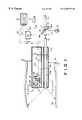
- FIG. 1is a schematic side view of a fluorescence endoscope in accordance with an embodiment of the present invention.
- a fluorescence endoscopein accordance with an embodiment of the present invention comprises an excitation light source 10 such as a SHG laser which generates excitation light L 1 , for instance, in a blue region, a condenser lens 11 which condenses the excitation light L 1 and a light guide 12 which is formed of optical fibers and is disposed so that the condensed excitation light L 1 enters the light guide 12 .
- an excitation light source 10such as a SHG laser which generates excitation light L 1 , for instance, in a blue region
- a condenser lens 11which condenses the excitation light L 1
- a light guide 12which is formed of optical fibers and is disposed so that the condensed excitation light L 1 enters the light guide 12 .
- the endoscopeis further provided with an illuminating light source 13 which emits white illuminating light L 2 in a direction perpendicular to the optical path of the excitation light L 1 , a filter wheel 14 which is disposed on the optical path of the excitation light L 1 at 45° thereto, and a drive means 15 which rotates the filter wheel 14 .
- the filter wheel 14is provided with a mirror 14 a and a dichroic mirror 14 b fixed thereto.
- the mirror 14 areflects the illuminating light as it is toward the condenser lens 11 .
- the dichroic mirror 14 breflects only a component of the illuminating light L 2 , which is white light, having a wavelength substantially equal to a peak wavelength of fluorescence L 3 to be described later toward the condenser lens 11 as measuring light L 2 ′.
- the filter wheel 14is provided with an opening through which the excitation light L 1 passes the filter wheel 14 to impinge upon the condenser lens 11 .
- the filter wheel 14is driven by the drive means 15 and is selectively positioned in one of a first position where the opening is on the optical path of the excitation light L 1 so that the excitation light L 1 passes the filter wheel 14 and impinges upon the condenser lens 11 , a second position where the mirror 14 a reflects the illuminating light L 2 toward the condenser lens 11 and a third position where the dichroic mirror 14 b reflects the measuring light L 2 ′ toward the condenser lens 11 .
- the light guide 12is contained in a forceps passage 17 B in a flexible probe 17 which is inserted into a body 16 .
- a beam splitter 19is disposed in the probe 17 and an objective lens 20 is disposed forward of the beam splitter 19 .
- the beam splitter 19reflects downward a part of light impinging thereon and transmits the other part of the light as will be described later.
- a excitation light cut filter 21 and a fluorescence image taking means 22are disposed in this order below the beam splitter 19 .
- the fluorescence image taking means 22may comprise, for instance, a CCD, and the fluorescence image taking means 22 is connected to an image processing system 23 and an image display system 24 which may comprise, for instance, a CRT.
- the light passing through the beam splitter 19impinges upon a normal image taking means 25 , which may comprise, for instance, a CCD.
- the normal image taking means 25is also connected to the image processing system 23 and the image display system 24 .
- a photosensitive material which has affinity to tumor and emits fluorescence when excited by lighthas been absorbed by a diagnostic part 30 of the body 16 .
- the photosensitive materialmay be, for instance, porphyrin.
- the illuminating light source 13When a normal image is to be observed, the illuminating light source 13 is energized, and the filter wheel 14 is rotated to the second position where the mirror 14 a reflects the illuminating light L 2 toward the condenser lens 11 .
- the illuminating light L 2 emitted from the illuminating light source 13is condensed by the condenser lens 11 and enters the light guide 12 .
- the illuminating light L 2propagates through the light guide 12 and emanates from the front end of the light guide 12 to illuminate the diagnostic part 30 .
- a part of the illuminating light L 2 reflected by the diagnostic part 30passes through the beam splitter 19 to impinge upon the normal image taking means 25 .
- a normal image of the diagnostic part 30 by the reflected illuminating light L 2is formed on the normal image taking means 25 by the objective lens 20 , and the normal image is taken by the normal image taking means 25 .
- An image signal S 2representing the normal image, output from the normal image taking means 25 is input into the image display means 24 and the normal image is displayed by the image display means 24 .
- An adjustable diaphragm 26is disposed between the objective lens 20 and the beam splitter 19 and is closed to a predetermined diameter to increase the depth of focus of the objective lens 20 when the normal image is taken.
- the excitation light source 10When a fluorescence image is to be taken, the excitation light source 10 is energized and the filter wheel 14 is rotated to the first position where the opening is on the optical path of the excitation light L 1 so that the excitation light L 1 passes the filter wheel 14 and impinges upon the condenser lens 11 .
- the excitation light L 1 emitted from the excitation light source 10is condensed by the condenser lens 11 and enters the light guide 12 .
- the excitation light L 1propagates through the light guide 12 and emanates from the front end of the light guide 12 to impinge upon the diagnostic part 30 .
- the excitation light L 1When the excitation light L 1 is projected onto the diagnostic part 30 , the photosensitive material which has been absorbed by the diagnostic part 30 emits fluorescence L 3 . A part of the fluorescence L 3 is reflected by the beam splitter 19 to impinge upon the fluorescence image taking means 22 . At this time a fluorescence image of the diagnostic part 30 by the fluorescence L 3 is formed on the fluorescence image taking means 22 by the objective lens 20 and the fluorescence image is taken by the fluorescence image taking means 22 . The excitation light L 1 which is reflected by the diagnostic part 30 and travels toward the fluorescence image taking means 22 is cut by the excitation light cut filter 21 .
- An image signal S 1representing the fluorescence image, output from the fluorescence image taking means 22 is input into the image display means 24 and the fluorescence image is displayed by the image display means 24 . Since the photosensitive material has affinity to tumor, only an image of the tumor part is basically displayed.
- the adjustable diaphragm 26When the fluorescence image is taken, the adjustable diaphragm 26 is full opened so that the weak fluorescence L 3 enters the fluorescence image taking means 22 as much as possible.
- the adjustable diaphragm 26When the adjustable diaphragm 26 is full opened, the depth of focus of the objective lens 20 is reduced and blur is apt to be generated in a part of the fluorescence image taken. Removal of such blur will be described hereinbelow.
- the fluorescence image signal S 1 output from the fluorescence image taking means 22is also input into the image processing system 23 and is subjected to an image restoration processing using a point spread function of the objective lens 20 . Specifically a deconvolution processing using the aforesaid various filters is carried out as the image restoration processing.
- g ( x,y )⁇ h ( x,y,x′,y′ ) f ( x′,y′ ) dx′dy′+n ( x,y )
- h(x, y, x′, y′)is a degradation function
- n(x,y)is noise.
- h(x, y, ⁇ , ⁇ )is a point spread function which is independent of the position ( ⁇ , ⁇ ) of a point on the original image.
- g ( x,y )⁇ h ( x ⁇ x′,y ⁇ y′ ) f ( x′, y′ ) dx′dy′+n ( x,y )
- F(u, v), G(u, v) and H(u, v)are Fourier transforms of f(x, y), g(x, y) and h(x, y), respectively, and H(u, v) is a transfer function of a system for converting an original image f(x, y) to a degraded image g(x, y).
- a reverse filterBy taking a reverse Fourier transform of G(u, v)/H(u, v), the original image can be restored. Accordingly 1/H(u, v) is referred to as “a reverse filter”.
- the image signal S 1 ′ which has been subjected to the image restoration processingis input into the image display means 24 and a fluorescence image is displayed by the image display means 24 on the basis of the image signal S 1 ′.
- the fluorescence imageis displayed on the image display means 24 together with a fluorescence image reproduced on the basis of the original image signal S 1 .
- the command for carrying out the image restoration processing on the image signal S 1is manually input by use of an input means 27 such as a keyboard. Accordingly, whether the image restoration processing is to be carried out can be selected.
- the illuminating light source 13is energized and the filter wheel 14 is rotated to the third position where the dichroic mirror 14 b reflects the measuring light L 2 ′ toward the condenser lens 11 .
- the component of the illuminating light L 2 having a wavelength substantially equal to a peak wavelength of fluorescence L 3is reflected by the dichroic mirror 14 b toward the condenser lens 11 as measuring light L 2 ′.
- the measuring light L 2 ′is condensed by the condenser lens 11 and enters the light guide 12 .
- the measuring light L 2 ′propagates through the light guide 12 and emanates from the front end of the light guide 12 to impinge upon the diagnostic part 30 .
- a part of the measuring light L 2 ′ reflected by the diagnostic part 30passes through the beam splitter 19 and impinges upon the normal image taking means 25 .
- an image (measurement image) of the diagnostic part 30 by the measuring light L 2 ′is formed on the normal image taking means 25 by the objective lens 20 , and the measurement image is taken by the normal image taking means 25 .
- An image signal S 2representing the measurement image, output from the normal image taking means 25 is input into the image processing system 23 .
- the adjustable diaphragm 26is kept closed.
- the adjustable diaphragm 26is full opened and an measurement image is taken by the fluorescence image taking means 22 .
- the measuring light L 2 ′is projected onto the diagnostic part 30 and a part of the measuring light L 2 ′ reflected by the diagnostic part 30 is reflected by the beam splitter 19 to impinge upon the fluorescence image taking means 22 .
- a measurement image of the diagnostic part 30 by the measuring light L 2 ′is formed on the fluorescence image taking means 22 by the objective lens 20 , and the measurement image is taken by the fluorescence image taking means 22 .
- An image signal S 1representing the measurement image, output from the fluorescence image taking means 22 is input into the image processing system 23 .
- the image signals S 2 and S 1represent images of the same part.
- the image processing system 23calculates a deterioration function h(x, y, x′, y′) for each position (x, y) on the basis of the image signals S 1 and S 2 thus input into the image processing system 23 .
- the image processing system 23stores the deterioration functions h(x, y, x′, y′) thus obtained in a built-in memory and reads out the same when the aforesaid image restoration processing is to be carried out.
- the processing of obtaining the deterioration functions h(x, y, x′, y′)is carried out just before a fluorescence image is taken and displayed.
- the position of the objective lens 20 relative to the diagnostic partis held unchanged from that when the degradation functions are obtained.
- an extremely accurate image restoration processingcan be carried out using the degradation functions h(x, y, x′, y′) which precisely reflect the actual position of the objective lens 20 relative to the diagnostic part 30 .
- a step of displaying a normal image of a tumor suspect portion and observing the same, a step of taking the measurement images with the adjustable diaphragm full opened and obtaining the degradation functions, and a step of taking a fluorescence image and restoring the fluorescence imageare performed in sequence.
- a single objective lens 20is used both for forming the normal image and the fluorescence image, and the normal image and the fluorescence image are taken by separate image taking means 25 and 22 .
- the normal image and the fluorescence imagemay be formed by separate objective optical systems.
- parallax between the objective optical systemscan cause distortion of the image.
- the image signals S 1 and S 2 output from the fluorescence image taking means 22 and the normal image taking means 25 when the measurement images are takenbe subjected to processing for correcting distortion of the images due to parallax between the objective optical systems.
- the correctioncan be performed by coordinate transformation using correction data depending on distortion of the images due to parallax which are stored in a look-up table.
- both an objective optical system and an image taking meansmay be used for taking a normal image and taking a fluorescence image.
- the single image taking meansmay take measurement images through the normal image taking system and the fluorescence image taking system at one time. Accordingly, it is necessary to take a measurement image through the normal image taking system with the adjustable diaphragm closed and then take a measurement image through the fluorescence image taking system with the adjustable diaphragm full opened.
- the present inventionmay be applied to a case where a fluorescence image formed by auto-fluorescence emitted from the intrinsic photosensitive material is taken.
Landscapes
- Life Sciences & Earth Sciences (AREA)
- Health & Medical Sciences (AREA)
- Surgery (AREA)
- Engineering & Computer Science (AREA)
- Heart & Thoracic Surgery (AREA)
- Animal Behavior & Ethology (AREA)
- Nuclear Medicine, Radiotherapy & Molecular Imaging (AREA)
- Optics & Photonics (AREA)
- Pathology (AREA)
- Radiology & Medical Imaging (AREA)
- Physics & Mathematics (AREA)
- Biomedical Technology (AREA)
- Veterinary Medicine (AREA)
- Medical Informatics (AREA)
- Molecular Biology (AREA)
- Biophysics (AREA)
- General Health & Medical Sciences (AREA)
- Public Health (AREA)
- Signal Processing (AREA)
- Endoscopes (AREA)
- Investigating, Analyzing Materials By Fluorescence Or Luminescence (AREA)
- Measuring And Recording Apparatus For Diagnosis (AREA)
- Image Processing (AREA)
- Closed-Circuit Television Systems (AREA)
- Image Analysis (AREA)
- Instruments For Viewing The Inside Of Hollow Bodies (AREA)
Abstract
Description
Claims (5)
Applications Claiming Priority (2)
| Application Number | Priority Date | Filing Date | Title |
|---|---|---|---|
| JP10-148666 | 1998-05-29 | ||
| JP14866698AJP3394447B2 (en) | 1998-05-29 | 1998-05-29 | Fluorescent endoscope |
Publications (1)
| Publication Number | Publication Date |
|---|---|
| US6280378B1true US6280378B1 (en) | 2001-08-28 |
Family
ID=15457913
Family Applications (1)
| Application Number | Title | Priority Date | Filing Date |
|---|---|---|---|
| US09/322,159Expired - Fee RelatedUS6280378B1 (en) | 1998-05-29 | 1999-05-28 | Fluorescence endoscope |
Country Status (2)
| Country | Link |
|---|---|
| US (1) | US6280378B1 (en) |
| JP (1) | JP3394447B2 (en) |
Cited By (30)
| Publication number | Priority date | Publication date | Assignee | Title |
|---|---|---|---|---|
| US20020035330A1 (en)* | 2000-07-14 | 2002-03-21 | Xillix Technologies Corporation | Compact fluorescent endoscopy video system |
| US6529768B1 (en)* | 1999-11-18 | 2003-03-04 | Fuji Photo Film Co., Ltd. | Method and apparatus for acquiring fluorescence images |
| US6899675B2 (en) | 2002-01-15 | 2005-05-31 | Xillix Technologies Corp. | Fluorescence endoscopy video systems with no moving parts in the camera |
| US6956610B1 (en)* | 1999-02-18 | 2005-10-18 | Linvatec Corporation | Shock mounting system for CCD camera |
| US20060161047A1 (en)* | 2003-09-19 | 2006-07-20 | Olympus Corporation | Endoscope |
| US20060241496A1 (en)* | 2002-01-15 | 2006-10-26 | Xillix Technologies Corp. | Filter for use with imaging endoscopes |
| US20070093691A1 (en)* | 2005-10-21 | 2007-04-26 | Pentax Corporation | Electronic endoscope |
| US7330749B1 (en) | 1999-03-17 | 2008-02-12 | Ekapot Bhunachet | Fluorescence electronic endoscopic system |
| US20080177140A1 (en)* | 2007-01-23 | 2008-07-24 | Xillix Technologies Corp. | Cameras for fluorescence and reflectance imaging |
| US20090059046A1 (en)* | 2006-02-13 | 2009-03-05 | Jai Corporation | Field Sequential Color Camera System |
| US20090236541A1 (en)* | 2008-03-24 | 2009-09-24 | General Electric Company | System and Methods for Optical Imaging |
| US20100002292A1 (en)* | 2008-07-04 | 2010-01-07 | Olympus Medical Systems Corp. | Light source device and endoscope apparatus using the same |
| US20110133064A1 (en)* | 2003-10-31 | 2011-06-09 | Art, Advanced Research Technologies Inc. | Time-domain method and apparatus for determining the depth and concentration of a fluorophore in a turbid medium |
| US20140031699A1 (en)* | 2012-07-26 | 2014-01-30 | Sony Corporation | Photodynamic diagnosis apparatus, photodynamic diagnosis method and device |
| US20150182107A1 (en)* | 2013-12-31 | 2015-07-02 | Timothy King | Switching Between White Light Imaging and Excitation Light Imaging Leaving Last Video Frame Displayed |
| US9386909B2 (en) | 2006-07-28 | 2016-07-12 | Novadaq Technologies Inc. | System and method for deposition and removal of an optical element on an endoscope objective |
| WO2016181076A1 (en) | 2015-05-12 | 2016-11-17 | Commissariat à l'énergie atomique et aux énergies alternatives | Method of correcting a fluorescence image |
| US9642532B2 (en) | 2008-03-18 | 2017-05-09 | Novadaq Technologies Inc. | Imaging system for combined full-color reflectance and near-infrared imaging |
| US9814378B2 (en) | 2011-03-08 | 2017-11-14 | Novadaq Technologies Inc. | Full spectrum LED illuminator having a mechanical enclosure and heatsink |
| US9877654B2 (en) | 2006-02-07 | 2018-01-30 | Novadaq Technologies Inc. | Near infrared imaging |
| US20180132708A1 (en)* | 2015-05-12 | 2018-05-17 | Commissariat A L'energie Atomique Et Aux Energies Alternatives | Device and method for observing an object, taking into consideration the distance between the device and the object |
| US10293122B2 (en) | 2016-03-17 | 2019-05-21 | Novadaq Technologies ULC | Endoluminal introducer with contamination avoidance |
| US10694151B2 (en) | 2006-12-22 | 2020-06-23 | Novadaq Technologies ULC | Imaging system with a single color image sensor for simultaneous fluorescence and color video endoscopy |
| US10869645B2 (en) | 2016-06-14 | 2020-12-22 | Stryker European Operations Limited | Methods and systems for adaptive imaging for low light signal enhancement in medical visualization |
| USD916294S1 (en) | 2016-04-28 | 2021-04-13 | Stryker European Operations Limited | Illumination and imaging device |
| US10980420B2 (en) | 2016-01-26 | 2021-04-20 | Stryker European Operations Limited | Configurable platform |
| US10992848B2 (en) | 2017-02-10 | 2021-04-27 | Novadaq Technologies ULC | Open-field handheld fluorescence imaging systems and methods |
| US11457797B2 (en)* | 2017-10-27 | 2022-10-04 | Sony Olympus Medical Solutions Inc. | Endoscopic device |
| US11602265B2 (en) | 2016-03-31 | 2023-03-14 | Sony Corporation | Control device, endoscopic imaging device, control method, program, and endoscopic system |
| US11930278B2 (en) | 2015-11-13 | 2024-03-12 | Stryker Corporation | Systems and methods for illumination and imaging of a target |
Families Citing this family (6)
| Publication number | Priority date | Publication date | Assignee | Title |
|---|---|---|---|---|
| JP2002034913A (en)* | 2000-07-27 | 2002-02-05 | Asahi Optical Co Ltd | Optical system of light source device of electronic endoscope system |
| KR100411631B1 (en)* | 2001-10-18 | 2003-12-18 | 주식회사 메디미르 | Fluorescence endoscope apparatus and a method for imaging tissue within a body using the same |
| EP1688083B1 (en) | 2003-11-20 | 2018-09-12 | Hamamatsu Photonics K.K. | Lymph node detector |
| JP2006014868A (en) | 2004-06-30 | 2006-01-19 | Hamamatsu Photonics Kk | Lymph node detecting apparatus |
| JP6071541B2 (en)* | 2012-12-27 | 2017-02-01 | キヤノン株式会社 | Endoscope optical system and endoscope |
| JP7219002B2 (en)* | 2017-09-11 | 2023-02-07 | i-PRO株式会社 | Endoscope |
Citations (3)
| Publication number | Priority date | Publication date | Assignee | Title |
|---|---|---|---|---|
| US4902115A (en) | 1986-09-22 | 1990-02-20 | Olympus Optical Co., Ltd. | Optical system for endoscopes |
| US4961110A (en)* | 1988-11-02 | 1990-10-02 | Olympus Optical Co., Ltd. | Endoscope apparatus |
| US5879284A (en) | 1996-12-10 | 1999-03-09 | Fuji Photo Film Co., Ltd. | Endoscope |
- 1998
- 1998-05-29JPJP14866698Apatent/JP3394447B2/ennot_activeExpired - Fee Related
- 1999
- 1999-05-28USUS09/322,159patent/US6280378B1/ennot_activeExpired - Fee Related
Patent Citations (3)
| Publication number | Priority date | Publication date | Assignee | Title |
|---|---|---|---|---|
| US4902115A (en) | 1986-09-22 | 1990-02-20 | Olympus Optical Co., Ltd. | Optical system for endoscopes |
| US4961110A (en)* | 1988-11-02 | 1990-10-02 | Olympus Optical Co., Ltd. | Endoscope apparatus |
| US5879284A (en) | 1996-12-10 | 1999-03-09 | Fuji Photo Film Co., Ltd. | Endoscope |
Cited By (61)
| Publication number | Priority date | Publication date | Assignee | Title |
|---|---|---|---|---|
| US6956610B1 (en)* | 1999-02-18 | 2005-10-18 | Linvatec Corporation | Shock mounting system for CCD camera |
| US7330749B1 (en) | 1999-03-17 | 2008-02-12 | Ekapot Bhunachet | Fluorescence electronic endoscopic system |
| US6529768B1 (en)* | 1999-11-18 | 2003-03-04 | Fuji Photo Film Co., Ltd. | Method and apparatus for acquiring fluorescence images |
| US8961403B2 (en) | 2000-07-14 | 2015-02-24 | Novadaq Technologies Inc. | Compact fluorescence endoscopy video system |
| US20050065406A1 (en)* | 2000-07-14 | 2005-03-24 | Xillix Technologies Corporation | Compact fluorescence endoscopy video system |
| US20100198010A1 (en)* | 2000-07-14 | 2010-08-05 | Novadaq Technologies Inc. | Compact fluorescence endoscopy video system |
| US7722534B2 (en) | 2000-07-14 | 2010-05-25 | Novadaq Technologies, Inc. | Compact fluorescence endoscopy video system |
| US6821245B2 (en)* | 2000-07-14 | 2004-11-23 | Xillix Technologies Corporation | Compact fluorescence endoscopy video system |
| US7341557B2 (en)* | 2000-07-14 | 2008-03-11 | Novadaq Technologies Inc. | Compact fluorescence endoscopy video system |
| US9968244B2 (en) | 2000-07-14 | 2018-05-15 | Novadaq Technologies ULC | Compact fluorescence endoscopy video system |
| US20100210904A1 (en)* | 2000-07-14 | 2010-08-19 | Novadaq Technologies Inc. | Compact fluorescence endoscopy video system |
| US20020035330A1 (en)* | 2000-07-14 | 2002-03-21 | Xillix Technologies Corporation | Compact fluorescent endoscopy video system |
| US10182709B2 (en) | 2002-01-15 | 2019-01-22 | Novadaq Technologies ULC | Filter for use with imaging endoscopes |
| US20050143627A1 (en)* | 2002-01-15 | 2005-06-30 | Xillix Technologies Corporation | Fluorescence endoscopy video systems with no moving parts in the camera |
| US6899675B2 (en) | 2002-01-15 | 2005-05-31 | Xillix Technologies Corp. | Fluorescence endoscopy video systems with no moving parts in the camera |
| US20060241496A1 (en)* | 2002-01-15 | 2006-10-26 | Xillix Technologies Corp. | Filter for use with imaging endoscopes |
| US20060161047A1 (en)* | 2003-09-19 | 2006-07-20 | Olympus Corporation | Endoscope |
| US20110133064A1 (en)* | 2003-10-31 | 2011-06-09 | Art, Advanced Research Technologies Inc. | Time-domain method and apparatus for determining the depth and concentration of a fluorophore in a turbid medium |
| US8084755B2 (en)* | 2003-10-31 | 2011-12-27 | Softscan Healthcare Group Ltd. | Time-domain method and apparatus for determining the depth and concentration of a fluorophore in a turbid medium |
| US20070015963A1 (en)* | 2005-05-04 | 2007-01-18 | Xillix Technologies Corp. | Filter for use with imaging endoscopes |
| US8630698B2 (en) | 2005-05-04 | 2014-01-14 | Novadaq Technologies, Inc. | Filter for use with imaging endoscopes |
| US20070093691A1 (en)* | 2005-10-21 | 2007-04-26 | Pentax Corporation | Electronic endoscope |
| US8734335B2 (en)* | 2005-10-21 | 2014-05-27 | Hoya Corporation | Electronic endoscope |
| US9877654B2 (en) | 2006-02-07 | 2018-01-30 | Novadaq Technologies Inc. | Near infrared imaging |
| US7948551B2 (en)* | 2006-02-13 | 2011-05-24 | Jai Corporation | Field sequential color camera system |
| US20090059046A1 (en)* | 2006-02-13 | 2009-03-05 | Jai Corporation | Field Sequential Color Camera System |
| US9386909B2 (en) | 2006-07-28 | 2016-07-12 | Novadaq Technologies Inc. | System and method for deposition and removal of an optical element on an endoscope objective |
| US10694152B2 (en) | 2006-12-22 | 2020-06-23 | Novadaq Technologies ULC | Imaging systems and methods for displaying fluorescence and visible images |
| US10694151B2 (en) | 2006-12-22 | 2020-06-23 | Novadaq Technologies ULC | Imaging system with a single color image sensor for simultaneous fluorescence and color video endoscopy |
| US11025867B2 (en) | 2006-12-22 | 2021-06-01 | Stryker European Operations Limited | Imaging systems and methods for displaying fluorescence and visible images |
| US11770503B2 (en) | 2006-12-22 | 2023-09-26 | Stryker European Operations Limited | Imaging systems and methods for displaying fluorescence and visible images |
| US20080177140A1 (en)* | 2007-01-23 | 2008-07-24 | Xillix Technologies Corp. | Cameras for fluorescence and reflectance imaging |
| US10779734B2 (en) | 2008-03-18 | 2020-09-22 | Stryker European Operations Limited | Imaging system for combine full-color reflectance and near-infrared imaging |
| US9642532B2 (en) | 2008-03-18 | 2017-05-09 | Novadaq Technologies Inc. | Imaging system for combined full-color reflectance and near-infrared imaging |
| US20090236541A1 (en)* | 2008-03-24 | 2009-09-24 | General Electric Company | System and Methods for Optical Imaging |
| US20100002292A1 (en)* | 2008-07-04 | 2010-01-07 | Olympus Medical Systems Corp. | Light source device and endoscope apparatus using the same |
| US8303493B2 (en)* | 2008-07-04 | 2012-11-06 | Olympus Medical Systems Corp. | Light source device and endoscope apparatus using the same |
| US9814378B2 (en) | 2011-03-08 | 2017-11-14 | Novadaq Technologies Inc. | Full spectrum LED illuminator having a mechanical enclosure and heatsink |
| US9480405B2 (en)* | 2012-07-26 | 2016-11-01 | Sony Corporation | Photodynamic diagnosis apparatus, photodynamic diagnosis method and device |
| US20140031699A1 (en)* | 2012-07-26 | 2014-01-30 | Sony Corporation | Photodynamic diagnosis apparatus, photodynamic diagnosis method and device |
| US20150182107A1 (en)* | 2013-12-31 | 2015-07-02 | Timothy King | Switching Between White Light Imaging and Excitation Light Imaging Leaving Last Video Frame Displayed |
| US10602918B2 (en)* | 2013-12-31 | 2020-03-31 | Karl Storz Imaging, Inc. | Switching between white light imaging and excitation light imaging leaving last video frame displayed |
| WO2016181076A1 (en) | 2015-05-12 | 2016-11-17 | Commissariat à l'énergie atomique et aux énergies alternatives | Method of correcting a fluorescence image |
| US20180132708A1 (en)* | 2015-05-12 | 2018-05-17 | Commissariat A L'energie Atomique Et Aux Energies Alternatives | Device and method for observing an object, taking into consideration the distance between the device and the object |
| US10634615B2 (en) | 2015-05-12 | 2020-04-28 | Commissariat A L'energie Atomique Et Aux Energies Alternatives | Method of correcting a fluorescence image |
| US11723526B2 (en)* | 2015-05-12 | 2023-08-15 | Commissariat A L'energie Atomique Et Aux Energies Alternatives | Device and method for observing an object, taking into consideration the distance between the device and the object |
| FR3036187A1 (en)* | 2015-05-12 | 2016-11-18 | Commissariat Energie Atomique | METHOD OF CORRECTING A FLUORESCENCE IMAGE |
| US11930278B2 (en) | 2015-11-13 | 2024-03-12 | Stryker Corporation | Systems and methods for illumination and imaging of a target |
| US10980420B2 (en) | 2016-01-26 | 2021-04-20 | Stryker European Operations Limited | Configurable platform |
| US11298024B2 (en) | 2016-01-26 | 2022-04-12 | Stryker European Operations Limited | Configurable platform |
| US10293122B2 (en) | 2016-03-17 | 2019-05-21 | Novadaq Technologies ULC | Endoluminal introducer with contamination avoidance |
| US11602265B2 (en) | 2016-03-31 | 2023-03-14 | Sony Corporation | Control device, endoscopic imaging device, control method, program, and endoscopic system |
| USD977480S1 (en) | 2016-04-28 | 2023-02-07 | Stryker European Operations Limited | Device for illumination and imaging of a target |
| USD916294S1 (en) | 2016-04-28 | 2021-04-13 | Stryker European Operations Limited | Illumination and imaging device |
| USD1065550S1 (en) | 2016-04-28 | 2025-03-04 | Stryker Corporation | Device for illumination and imaging of a target |
| US11756674B2 (en) | 2016-06-14 | 2023-09-12 | Stryker European Operations Limited | Methods and systems for adaptive imaging for low light signal enhancement in medical visualization |
| US10869645B2 (en) | 2016-06-14 | 2020-12-22 | Stryker European Operations Limited | Methods and systems for adaptive imaging for low light signal enhancement in medical visualization |
| US10992848B2 (en) | 2017-02-10 | 2021-04-27 | Novadaq Technologies ULC | Open-field handheld fluorescence imaging systems and methods |
| US11140305B2 (en) | 2017-02-10 | 2021-10-05 | Stryker European Operations Limited | Open-field handheld fluorescence imaging systems and methods |
| US12028600B2 (en) | 2017-02-10 | 2024-07-02 | Stryker Corporation | Open-field handheld fluorescence imaging systems and methods |
| US11457797B2 (en)* | 2017-10-27 | 2022-10-04 | Sony Olympus Medical Solutions Inc. | Endoscopic device |
Also Published As
| Publication number | Publication date |
|---|---|
| JPH11332820A (en) | 1999-12-07 |
| JP3394447B2 (en) | 2003-04-07 |
Similar Documents
| Publication | Publication Date | Title |
|---|---|---|
| US6280378B1 (en) | Fluorescence endoscope | |
| US5879284A (en) | Endoscope | |
| KR100411631B1 (en) | Fluorescence endoscope apparatus and a method for imaging tissue within a body using the same | |
| US4768513A (en) | Method and device for measuring and processing light | |
| JP3579638B2 (en) | Endoscope device | |
| JP5735031B2 (en) | Compact fluorescent endoscope imaging system | |
| US7961213B2 (en) | Image pickup apparatus using an imaging unit including an etalon and calibration method therefor | |
| US7635330B2 (en) | Fluorescent endoscope system having improved image detection module | |
| US6026319A (en) | Fluorescence detecting system | |
| US20100165089A1 (en) | Apparatus for caries detection | |
| US20100128959A1 (en) | Method for detection of caries | |
| US20120013722A1 (en) | Apparatus and method for caries detection | |
| US20070285771A1 (en) | Endoscope system | |
| JP2001137173A (en) | Fluorescent image measurement method and equipment | |
| US6749562B2 (en) | Video endoscope and system incorporating the same | |
| JP3664541B2 (en) | Fluorescence diagnostic equipment | |
| US6492646B1 (en) | Method of and apparatus for obtaining fluorescence image | |
| JPH02200237A (en) | Fluorescent observing method | |
| JPH0838460A (en) | Brain activity measuring device | |
| JP2012016385A (en) | Fluorescence observation apparatus | |
| JP3665554B2 (en) | Electronic endoscope device | |
| JP7562592B2 (en) | Techniques for identifying the composition of anatomical targets | |
| JP5592715B2 (en) | Image processing apparatus and image processing method | |
| US20240065525A1 (en) | Method, computer program, and data processing unit for creating at least one correction value for correcting fluorescence intensities in a fluorescence image, and optical observation system | |
| JP2001128927A (en) | Method and device for producing fluorescent image |
Legal Events
| Date | Code | Title | Description |
|---|---|---|---|
| AS | Assignment | Owner name:FUJI PHOTO FILM CO., LTD., JAPAN Free format text:ASSIGNMENT OF ASSIGNORS INTEREST;ASSIGNORS:KAZUHIRO, TSUJITA;SENDAI, TOMONARI;REEL/FRAME:010008/0382 Effective date:19990521 | |
| FEPP | Fee payment procedure | Free format text:PAYOR NUMBER ASSIGNED (ORIGINAL EVENT CODE: ASPN); ENTITY STATUS OF PATENT OWNER: LARGE ENTITY | |
| FPAY | Fee payment | Year of fee payment:4 | |
| AS | Assignment | Owner name:FUJIFILM CORPORATION, JAPAN Free format text:ASSIGNMENT OF ASSIGNORS INTEREST;ASSIGNOR:FUJIFILM HOLDINGS CORPORATION (FORMERLY FUJI PHOTO FILM CO., LTD.);REEL/FRAME:018904/0001 Effective date:20070130 Owner name:FUJIFILM CORPORATION,JAPAN Free format text:ASSIGNMENT OF ASSIGNORS INTEREST;ASSIGNOR:FUJIFILM HOLDINGS CORPORATION (FORMERLY FUJI PHOTO FILM CO., LTD.);REEL/FRAME:018904/0001 Effective date:20070130 | |
| FPAY | Fee payment | Year of fee payment:8 | |
| REMI | Maintenance fee reminder mailed | ||
| LAPS | Lapse for failure to pay maintenance fees | ||
| STCH | Information on status: patent discontinuation | Free format text:PATENT EXPIRED DUE TO NONPAYMENT OF MAINTENANCE FEES UNDER 37 CFR 1.362 | |
| FP | Lapsed due to failure to pay maintenance fee | Effective date:20130828 |