US6280157B1 - Sealless integral-motor pump with regenerative impeller disk - Google Patents
Sealless integral-motor pump with regenerative impeller diskDownload PDFInfo
- Publication number
- US6280157B1 US6280157B1US09/342,588US34258899AUS6280157B1US 6280157 B1US6280157 B1US 6280157B1US 34258899 AUS34258899 AUS 34258899AUS 6280157 B1US6280157 B1US 6280157B1
- Authority
- US
- United States
- Prior art keywords
- fluid
- rotor disk
- housing
- fluid pump
- bearings
- Prior art date
- Legal status (The legal status is an assumption and is not a legal conclusion. Google has not performed a legal analysis and makes no representation as to the accuracy of the status listed.)
- Expired - Lifetime
Links
- 230000001172regenerating effectEffects0.000titleclaimsabstractdescription35
- 239000012530fluidSubstances0.000claimsabstractdescription107
- 238000004804windingMethods0.000claimsabstractdescription26
- 238000011144upstream manufacturingMethods0.000claimsabstractdescription6
- 230000005611electricityEffects0.000claimsabstractdescription3
- 238000005086pumpingMethods0.000claimsdescription18
- 230000001052transient effectEffects0.000claimsdescription5
- 238000000926separation methodMethods0.000claims1
- 239000000725suspensionSubstances0.000description6
- 238000006073displacement reactionMethods0.000description5
- 239000000463materialSubstances0.000description5
- 239000000654additiveSubstances0.000description2
- 230000000996additive effectEffects0.000description2
- 230000000712assemblyEffects0.000description2
- 238000000429assemblyMethods0.000description2
- 230000008878couplingEffects0.000description2
- 238000010168coupling processMethods0.000description2
- 238000005859coupling reactionMethods0.000description2
- 238000004519manufacturing processMethods0.000description2
- 229910000906BronzeInorganic materials0.000description1
- XAGFODPZIPBFFR-UHFFFAOYSA-NaluminiumChemical compound[Al]XAGFODPZIPBFFR-UHFFFAOYSA-N0.000description1
- 229910052782aluminiumInorganic materials0.000description1
- 230000005540biological transmissionEffects0.000description1
- 239000010974bronzeSubstances0.000description1
- KUNSUQLRTQLHQQ-UHFFFAOYSA-Ncopper tinChemical compound[Cu].[Sn]KUNSUQLRTQLHQQ-UHFFFAOYSA-N0.000description1
- 230000005672electromagnetic fieldEffects0.000description1
- 230000007613environmental effectEffects0.000description1
- 229910000078germaneInorganic materials0.000description1
- 238000009499grossingMethods0.000description1
- 239000000696magnetic materialSubstances0.000description1
- 238000000034methodMethods0.000description1
- 229920000642polymerPolymers0.000description1
- 230000035939shockEffects0.000description1
- 239000007787solidSubstances0.000description1
Images


Classifications
- F—MECHANICAL ENGINEERING; LIGHTING; HEATING; WEAPONS; BLASTING
- F04—POSITIVE - DISPLACEMENT MACHINES FOR LIQUIDS; PUMPS FOR LIQUIDS OR ELASTIC FLUIDS
- F04D—NON-POSITIVE-DISPLACEMENT PUMPS
- F04D29/00—Details, component parts, or accessories
- F04D29/04—Shafts or bearings, or assemblies thereof
- F04D29/046—Bearings
- F04D29/048—Bearings magnetic; electromagnetic
- F—MECHANICAL ENGINEERING; LIGHTING; HEATING; WEAPONS; BLASTING
- F04—POSITIVE - DISPLACEMENT MACHINES FOR LIQUIDS; PUMPS FOR LIQUIDS OR ELASTIC FLUIDS
- F04D—NON-POSITIVE-DISPLACEMENT PUMPS
- F04D13/00—Pumping installations or systems
- F04D13/02—Units comprising pumps and their driving means
- F04D13/06—Units comprising pumps and their driving means the pump being electrically driven
- F04D13/0666—Units comprising pumps and their driving means the pump being electrically driven the motor being of the plane gap type
- F—MECHANICAL ENGINEERING; LIGHTING; HEATING; WEAPONS; BLASTING
- F04—POSITIVE - DISPLACEMENT MACHINES FOR LIQUIDS; PUMPS FOR LIQUIDS OR ELASTIC FLUIDS
- F04D—NON-POSITIVE-DISPLACEMENT PUMPS
- F04D15/00—Control, e.g. regulation, of pumps, pumping installations or systems
- F04D15/0072—Installation or systems with two or more pumps, wherein the flow path through the stages can be changed, e.g. series-parallel
- F—MECHANICAL ENGINEERING; LIGHTING; HEATING; WEAPONS; BLASTING
- F04—POSITIVE - DISPLACEMENT MACHINES FOR LIQUIDS; PUMPS FOR LIQUIDS OR ELASTIC FLUIDS
- F04D—NON-POSITIVE-DISPLACEMENT PUMPS
- F04D5/00—Pumps with circumferential or transverse flow
- F04D5/002—Regenerative pumps
- F—MECHANICAL ENGINEERING; LIGHTING; HEATING; WEAPONS; BLASTING
- F04—POSITIVE - DISPLACEMENT MACHINES FOR LIQUIDS; PUMPS FOR LIQUIDS OR ELASTIC FLUIDS
- F04D—NON-POSITIVE-DISPLACEMENT PUMPS
- F04D5/00—Pumps with circumferential or transverse flow
- F04D5/002—Regenerative pumps
- F04D5/003—Regenerative pumps of multistage type
- F04D5/006—Regenerative pumps of multistage type the stages being axially offset
Definitions
- This inventionrelates generally to fluid pumps and more particularly to high-pressure-rise, low-flow-rate charging pumps for providing make-up fluids to closed high-pressure systems.
- Sealless pumpsFor applications such as charging pumps for supplying make-up fluid to closed high-pressure systems, it is necessary to employ pumps capable of supplying relatively low-flow-rate fluid at high pressure. It is desirable for such pumps to be highly leak resistant because of the types of fluids and the pressures involved. The most favored method of providing such leak resistance is by employment of sealless pumps. Sealless pumps often incorporate motors located inside the pump case, so there are no shaft pass-throughs to seal against leakage of the pumped fluid.
- rotodynamic pumpsare less efficient than are positive displacement pumps, they have the advantage of being much more amenable to sealless designs than are reciprocating positive displacement designs. Rotodynamic pumps are also more easily configured as sealless multi-stage machines, which permits their use in very high pressure applications. Thus, reciprocating positive displacement pumps, although more efficient than single-stage rotodynamic pumps, lose some of that efficiency advantage when multi-stage sealless features are employed.
- a fluid pumpcomprising; a housing and having at least one fluid passage extending circumferentially between at least one fluid inlet port and at least one fluid discharge port, said ports being separated by an interruption of said fluid passage located upstream of each said inlet and downstream of each said discharge; at least one rotatable rotatable rotor disk rotatably supported within said housing and having a plurality of substantially radially oriented impeller vanes situated about the periphery thereof within said circumferentially extending fluid passage, the disk also having a plurality of permanent magnets embedded therein in a circular locus about an axis rotation of said disk, said magnets being sealed against pumped fluid; at least one set of motor windings encased in at least one wall of said housing axially adjacent the permanent magnets in said at least one regenerative rotor disk and also sealed against pumped fluid; and means for controlling a flow of electricity through said motor windings to rotatably drive said rotor disk.
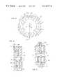
- FIG. 1 ais a fragmentary schematic radial sectional view of a single stage of a single pass regenerative pump
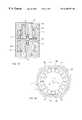
- FIG. 1 bis a schematic axial sectional view, along line b—b of FIG. 1 a, of a single stage sealless axially magnetically unbalanced embodiment of a single-pass regenerative pump;
- FIG. 1 cis a fragmentary schematic axial sectional view, along line c—c of FIG. 1 a, of a single stage of an axially magnetically balanced embodiment of a sealless single-pass regenerative pump of the invention;
- FIG. 1 dis a schematic axial sectional view of a sealless two-stage, single-pass regenerative pump according to the invention
- FIG. 2 ais a fragmentary schematic radial sectional view of a sealless two-pass regenerative pump
- FIG. 2 bis a schematic axial section, along line b—b of FIG. 2 a, of a sealless two-stage, two-pass regenerative pump according to the invention
- FIG. 3 ais a fragmentary axial sectional view of a rotor disk mounted on a shaft supported in product-lubricated bearings of a sealless pump;
- FIG. 3 bis a view, as in FIG. 3 a, of a shaft supported in magnetic bearings in a sealless pump;
- FIG. 4 ais a fragmentary axial sectional view of a rotor disk supported on product-lubricated bearings on a stationary shaft of a sealless pump;
- FIG. 4 bis a view, as in FIG. 4 a, of a rotor supported on magnetic bearings;
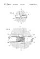
- FIG. 5is a fragmentary schematic view of a single stage of another embodiment, as in FIG. 1 c, of the axially magnetically balanced sealless integral motor regenerative rotor disk pump of the invention
- FIGS. 6 a and 6 bare fragmentary sectional illustrations of the shaft and the regenerative rotor disk, respectively, rotatably supported on conical magnetic bearings in the housing;
- FIG. 6 cis fragmentary sectional illustration of a recess in the housing for supporting either the shaft or the rotor disk on magnetic bearings.
- FIG. 1 ashows a partially sectional view of a single stage of a single pass regenerative pump.
- the pumphas a housing 20 with a single inlet port 25 and a single discharge port 30 which are connected by a fluid passage 27 extending circumferentially between the inlet and outlet ports.
- An interruption 29 of the fluid passageseparates the upstream edge of the inlet port 25 and the downstream edge of the discharge port 30 .
- fluid entering the inlet port 25is caught by impeller vanes 12 on the rotor 10 , which is rotating on a shaft 15 supported in the axial endwalls of the housing 20 , and driven along the fluid passage 27 to the discharge port 30 .
- the interruption 29 of the passageguides the fluid into the discharge port.
- the ports 25 , 30are shown with corners only as a simplified representation, but are normally provided with radii appropriate to the fluid being pumped in accordance with well known porting practice.
- the vanes 12are shown as straight and radial for the sake of illustrative simplicity. In fact, they may be straight with an inclination angle to the axis or the tangent of the rotor disk 10 , and/or they may be curved in the axial and/or radial direction.
- the specific applicationdetermines the vane configuration. Axially opposite vanes of the disk may be offset from each other or may be axially aligned.
- the single-pass rotors shownare each radially hydrodynamically unbalanced due to the pressure rise between the inlet port 25 and the discharge port 30 in the fluid passage 27 which results in a resultant radial hydrodynamic force approximately opposite to the discharge port 30 .
- these hydrodynamic forcesmay be offset by placement of the inlet and discharge ports diametrically opposite in two stage pumps or by radially distributing them about the housings to balance the hydrodynamic forces in pumps exceeding two stages.
- FIGS. 1 b and 1 care views along line b/c—b/c of FIG. 1 a and show the integral motor features of the regenerative rotor pump.
- a brushless DC motoris provided by means of the embedded circular array of permanent magnets 110 in the rotor disk 10 in conjunction with a stator comprising the motor windings 120 encased in the housing 20 .
- the resulting magnetic coupling between the permanent magnets 110 and motor windings 120provides the brushless motor drive desired for the sealless pump.
- FIG. 1 b and 1 care views along line b/c—b/c of FIG. 1 a and show the integral motor features of the regenerative rotor pump.
- a brushless DC motoris provided by means of the embedded circular array of permanent magnets 110 in the rotor disk 10 in conjunction with a stator comprising the motor windings 120 encased in the housing 20 .
- the resulting magnetic coupling between the permanent magnets 110 and motor windings 120provides the brushless motor drive
- FIG. 1 billustrates an axially magnetically unbalanced rotor disk 10 with embedded permanent magnets 110 on one face adjacent to motor windings 120 embedded in the housing 20 and powered by electric current introduced through electric leads 240 which are fed through the stationary housing 20 to a motor controller 250 .
- the magnets 110 and motor windings 120are sealed against contact with the pumped fluid.
- the shaft 15 on which the disk 10 is mountedis supported in the housing 20 in bearings 40 which may be of journal or antifriction types.
- the fluid passage 27is shown with a rectangular cross-section, again only as a simplified representation, but will preferably be provided with a cross-sectional geometry compatible with the regenerative flow profile of the pumped fluid caused by the pumping action of the impeller vanes 12 .
- FIG. 1 cis of a single stage of an axially magnetically balanced integral motor regenerative rotor disk 10 ′.
- permanent magnets 110are embedded in both faces of the rotor disk 10 and are rotatably driven by electromagnetic forces from the motor windings 120 in the walls of the housing 20 adjacent to the web of the rotor disk.
- FIG. 5An alternative embodiment of this axially magnetically balanced pump is shown in FIG. 5, in which a single set of permanent magnets 210 are embedded in the rotor 10 ′′ to react to motor windings 120 in both axially adjacent housing walls.
- Thishas the advantage of reducing the mass and volume and smoothing the radial profile of the web of the rotor disk 10 ′′ relative to that of disk 10 ′ in FIG. 1 c, thereby simplifying design and fabrication of the rotor disk 10 ′′ and the axially adjacent walls of the housing 20 .
- FIGS. 1 d and 2 bshow two stage sealless regenerative pumps, one-pass and two-pass versions, respectively.
- the housing 20 in all Figs.is shown schematically without seams.
- the housingmay be comprised of a plurality of torroidal disks bounding a plurality of rotor disks with solid endwalls enclosing the disks.
- Such housing assembly detailis not germane to the invention and is thus not illustrated.
- the pumpsare axially magnetically balanced due to the oppositely situated motor windings 120 in the endwalls of the housing 20 acting on the permanent magnets 110 embedded in the faces of the disks 10 adjacent to the endwalls in which the windings are encased.
- the housings 20support the shafts 15 in bearings 40 .
- Regenerative rotor disks 10 with substantially radially oriented impeller vanes 12are mounted on shafts 15 and rotate within fluid passages 27 (not visible in FIG. 2 b ) between inlet ports 25 and discharge ports 30 , separated by fluid passage interruptions 29 .
- Permanent magnets 110are embedded in the rotor disks 10 and are electromagnetically driven by the motor windings 120 in the endwalls of the housing 20 .
- thrust bearing assemblies 60are provided between the stages to prevent the rotors rubbing the housing walls in case of mechanical or hydraulic axial shocks. In some service, thrust bearings may not be needed; therefore, when included, they do not contact the rotors during normal operation except when an axial upset is introduced to the system.
- the thrust bearing assemblies 60 and the radial bearings 40may be product (or pumpage) lubricated journals or anti-friction bearings, or they may be magnetic bearings. The particular type is determined by service and performance factors.
- FIGS. 3 a, 3 b, 4 a, and 4 bare illustrated as radial bearings. These may be journals or anti-friction radial mechanical bearings 140 (FIGS. 3 a and 4 a ) which may be product (or pumpage) lubricated and cooled. Alternatively, they may be magnetic bearings comprised of permanent magnets 210 , 230 embedded in the rotating member 10 ′, 10 ′′, 15 , 115 and electromagnets (or, optionally, permanent magnets) opposedly embedded in the stationary member 15 ′′, 20 to provide the required magnetic support. In the case where electromagnets are provided in the stationary member, electric leads 240 are fed out to an outside power source. These radial bearing systems provide radial support to the rotating member(s) within or on the stationary member(s).
- the single-stage rotor 10 ′′ shown in FIG. 5is axially magnetically balanced by magnetic forces between the motor windings 120 in the housing 20 and the permanent magnets 210 in the rotor. Only a single stage is illustrated, but any number of magnetically balanced stages may be mounted on the shaft 15 in added sections of the housing 20 .
- the rotor 10 ′′has the same impeller blades 12 , and the housing has the same fluid passage as discussed above, but here each stage is axially magnetically balanced, independently of any other stages.
- FIGS. 6 a and 6 bshow one type of conical magnetic bearings for use with a rotor made from non-magnetizable material such as aluminum, bronze, polymers, etc.
- the rotatable shaft 15 ′is supported on magnetic bearings comprising permanent magnets 315 in the shaft and electromagnets 320 in the housing wall 20 ′.
- FIG. 6 bshows a rotor supported on conical bearings of the housing 20 ′′ with no shaft.
- the rotating memberrotor 10 *
- the rotating member 6 ahas permanent magnets 310 arrayed about opposed conic recesses radially centered on the rotor disk.
- the rotating memberbe made of a magnetizable material.
- the electromagnets and, if used, permanent magnetsact directly upon the magnetizable rotating member to create the magnetic suspension.
- the rotating membermay alternatively be provided with a magnetizable susceptor at the appropriate location. Whether to locate the projections on the housing or on the disk is determined by manufacturing considerations, since the magnetic bearings are equally effective in both cases. In the example illustrated in FIG.
- electromagnets 320 or permanent magnets 310are arrayed about conic axial projections of the housing 20 ′′.
- the force field created by these magnetsprovides magnetic combined radial and axial suspension to the rotor disk 10 * without use of a shaft.
- the projections and recesses abovehave been described as conical, but may be of any form, such as hemispheric, cylindrical, or combinations of forms.
- the permanent magnets 310 , 315are embedded in the rotatable rotor disk 10 * or shaft 15 ′, while the electromagnets 320 are preferably provided on the conic projection of the housing 20 ′′ or the shaft 15 ′.
- the stand-off journals 26may be of any suitable bearing material for service during start-up or transient operating conditions and are usually not in contact with the rotating member during steady-state operation of the fluid pump.
- the rotor diskis made from, or has a susceptor feature made from a magnetizable material
- permanent magnets in the diskmay not be required for the magnetic suspension. However, they are still needed for the brushless DC integral-motor rotor feature previously described.
- a combined rotor drive and magnetic bearing suspensionmay be achieved by locating at least some of the permanent magnets in a radial position in the rotor such that they can respond to both the electromagnetic fields of the motor windings and the magnetic force field of the suspension bearing electromagnets.
- permanent magnets, if neededare embedded in the rotary member; and the motor windings and the electromagnets are embedded in the stationary member, so that no rotating electrical contact is needed.
- This inventionprovides the advantages of an integral-motor pump of a rotodynamic type which is readily amenable to sealless design, multistaging, and operation with less than all stages running.
- operating total pressure-risecan be accurately varied as required.
- operation of multiple stages in serieswould provide a substantially additive final discharge pressure; while operation of the same pump stages in parallel would provide substantially additive final discharge volume.
- the pumpcan be operated with one, some, or all stages of a multistage configuration running. This, along with the manifolding above, permits previously unattainable versatility of operation.
- the regenerative impeller-disk pump described hereinhas the advantage of being readily multistaged due to the fact that the suction and discharge ports are at the periphery of the pumping chamber. Thus, fluid passing from one stage or one phase to the next can do so without power-consuming provisions for directing the fluid radially inward to a central suction port as would be required with a standard centrifugal pump. This feature results in increased pumping efficiency.
Landscapes
- Engineering & Computer Science (AREA)
- Mechanical Engineering (AREA)
- General Engineering & Computer Science (AREA)
- Physics & Mathematics (AREA)
- Electromagnetism (AREA)
- Structures Of Non-Positive Displacement Pumps (AREA)
Abstract
Description
Claims (30)
Priority Applications (5)
| Application Number | Priority Date | Filing Date | Title |
|---|---|---|---|
| US09/342,588US6280157B1 (en) | 1999-06-29 | 1999-06-29 | Sealless integral-motor pump with regenerative impeller disk |
| EP00305428AEP1065383B1 (en) | 1999-06-29 | 2000-06-28 | Sealless integral-motor pump with regenerative impeller disc |
| DE60015018TDE60015018T2 (en) | 1999-06-29 | 2000-06-28 | Sealless integrated motor pump with side channel impeller |
| JP2000195396AJP2001123978A (en) | 1999-06-29 | 2000-06-29 | Sealless integral pump and motor having regenerative impeller disc |
| HK01104424.7AHK1035019B (en) | 1999-06-29 | 2001-06-27 | Sealless integral-motor pump with regenerative impeller disc |
Applications Claiming Priority (1)
| Application Number | Priority Date | Filing Date | Title |
|---|---|---|---|
| US09/342,588US6280157B1 (en) | 1999-06-29 | 1999-06-29 | Sealless integral-motor pump with regenerative impeller disk |
Publications (1)
| Publication Number | Publication Date |
|---|---|
| US6280157B1true US6280157B1 (en) | 2001-08-28 |
Family
ID=23342458
Family Applications (1)
| Application Number | Title | Priority Date | Filing Date |
|---|---|---|---|
| US09/342,588Expired - LifetimeUS6280157B1 (en) | 1999-06-29 | 1999-06-29 | Sealless integral-motor pump with regenerative impeller disk |
Country Status (4)
| Country | Link |
|---|---|
| US (1) | US6280157B1 (en) |
| EP (1) | EP1065383B1 (en) |
| JP (1) | JP2001123978A (en) |
| DE (1) | DE60015018T2 (en) |
Cited By (59)
| Publication number | Priority date | Publication date | Assignee | Title |
|---|---|---|---|---|
| US6524083B2 (en)* | 2000-04-25 | 2003-02-25 | Aisan Kogyo Kabushiki Kaisha | Magnetic coupling pump |
| US20030185979A1 (en)* | 2002-03-29 | 2003-10-02 | Nelson Douglas M. | Method and apparatus for preparing vaporized reactants for chemical vapor deposition |
| US6668556B2 (en) | 2002-04-18 | 2003-12-30 | Eco Oxygen Technologies, Llc. | Gas transfer energy recovery and effervescence prevention apparatus and method |
| US20040028521A1 (en)* | 2000-12-14 | 2004-02-12 | Zlatko Penzar | Feed pump |
| US20040234399A1 (en)* | 2001-08-21 | 2004-11-25 | Lopatinsky Edward L. | Integrated motorized pump |
| US20050254936A1 (en)* | 2004-05-12 | 2005-11-17 | Aisan Kogyo Kabushiki Kaisha | Fuel pump |
| US20060275154A1 (en)* | 2005-06-03 | 2006-12-07 | Ti Group Automotive Systems, L.L.C. | Fuel Pump |
| US7320749B2 (en) | 2004-02-09 | 2008-01-22 | Eco-Oxygen Technologies, Llc | Method and apparatus for control of a gas or chemical |
| US20080054745A1 (en)* | 2006-08-31 | 2008-03-06 | Martin Sentmanat | Modular magneto-mechanical device |
| US7402276B2 (en) | 2003-07-14 | 2008-07-22 | Cooper Paul V | Pump with rotating inlet |
| US7470392B2 (en) | 2003-07-14 | 2008-12-30 | Cooper Paul V | Molten metal pump components |
| US20090010781A1 (en)* | 2007-07-04 | 2009-01-08 | Fu Zhun Precision Industry (Shen Zhen) Co., Ltd. | Bearing structure for cooling fan |
| CN100460687C (en)* | 2004-08-30 | 2009-02-11 | 株式会社东芝 | Fluid pump for cooling |
| US7507367B2 (en) | 2002-07-12 | 2009-03-24 | Cooper Paul V | Protective coatings for molten metal devices |
| US20090169399A1 (en)* | 2007-12-27 | 2009-07-02 | Metal Industries Research&Development Centre | Ultra-thin miniature pump |
| US7566397B2 (en) | 2004-02-09 | 2009-07-28 | Eco Oxygen Technologies, Llc | Superoxygenation of raw wastewater for odor/corrosion control |
| US7731891B2 (en) | 2002-07-12 | 2010-06-08 | Cooper Paul V | Couplings for molten metal devices |
| US20100172777A1 (en)* | 2007-07-02 | 2010-07-08 | Borgwarner Inc. | Inlet design for a pump assembly |
| US20100218747A1 (en)* | 2007-09-27 | 2010-09-02 | Johannes Deichmann | Fuel Pump for Delivering Fuel from a Reservoir to an Internal Combusion Engine |
| US7906068B2 (en) | 2003-07-14 | 2011-03-15 | Cooper Paul V | Support post system for molten metal pump |
| US20120013276A1 (en)* | 2009-07-09 | 2012-01-19 | Rabal Clifford R | Electromagnetic motor |
| US8178037B2 (en) | 2002-07-12 | 2012-05-15 | Cooper Paul V | System for releasing gas into molten metal |
| US8337746B2 (en) | 2007-06-21 | 2012-12-25 | Cooper Paul V | Transferring molten metal from one structure to another |
| US8361379B2 (en) | 2002-07-12 | 2013-01-29 | Cooper Paul V | Gas transfer foot |
| US8366993B2 (en) | 2007-06-21 | 2013-02-05 | Cooper Paul V | System and method for degassing molten metal |
| US20130093295A1 (en)* | 2009-07-09 | 2013-04-18 | Clifford R. Rabal | Direct Current Brushless Motor |
| US8444911B2 (en) | 2009-08-07 | 2013-05-21 | Paul V. Cooper | Shaft and post tensioning device |
| US8449814B2 (en) | 2009-08-07 | 2013-05-28 | Paul V. Cooper | Systems and methods for melting scrap metal |
| US8465133B2 (en) | 2010-09-27 | 2013-06-18 | Xerox Corporation | Ink pump with fluid and particulate return flow path |
| US8524146B2 (en) | 2009-08-07 | 2013-09-03 | Paul V. Cooper | Rotary degassers and components therefor |
| US8535603B2 (en) | 2009-08-07 | 2013-09-17 | Paul V. Cooper | Rotary degasser and rotor therefor |
| US8613884B2 (en) | 2007-06-21 | 2013-12-24 | Paul V. Cooper | Launder transfer insert and system |
| US8714914B2 (en) | 2009-09-08 | 2014-05-06 | Paul V. Cooper | Molten metal pump filter |
| US8888105B1 (en) | 2013-05-29 | 2014-11-18 | Stephen J. Andrews | Mechanical seal system |
| US9011761B2 (en) | 2013-03-14 | 2015-04-21 | Paul V. Cooper | Ladle with transfer conduit |
| US9108244B2 (en) | 2009-09-09 | 2015-08-18 | Paul V. Cooper | Immersion heater for molten metal |
| US9156087B2 (en) | 2007-06-21 | 2015-10-13 | Molten Metal Equipment Innovations, Llc | Molten metal transfer system and rotor |
| US9205490B2 (en) | 2007-06-21 | 2015-12-08 | Molten Metal Equipment Innovations, Llc | Transfer well system and method for making same |
| US9249806B2 (en) | 2011-02-04 | 2016-02-02 | Ti Group Automotive Systems, L.L.C. | Impeller and fluid pump |
| US9410744B2 (en) | 2010-05-12 | 2016-08-09 | Molten Metal Equipment Innovations, Llc | Vessel transfer insert and system |
| US9409232B2 (en) | 2007-06-21 | 2016-08-09 | Molten Metal Equipment Innovations, Llc | Molten metal transfer vessel and method of construction |
| US20160298632A1 (en)* | 2013-12-03 | 2016-10-13 | Q.E.D. Environmental Systems, Inc. | Groundwater Sampling Pump |
| US9643247B2 (en) | 2007-06-21 | 2017-05-09 | Molten Metal Equipment Innovations, Llc | Molten metal transfer and degassing system |
| US9903383B2 (en) | 2013-03-13 | 2018-02-27 | Molten Metal Equipment Innovations, Llc | Molten metal rotor with hardened top |
| US10052688B2 (en) | 2013-03-15 | 2018-08-21 | Molten Metal Equipment Innovations, Llc | Transfer pump launder system |
| US10138892B2 (en) | 2014-07-02 | 2018-11-27 | Molten Metal Equipment Innovations, Llc | Rotor and rotor shaft for molten metal |
| US10267314B2 (en) | 2016-01-13 | 2019-04-23 | Molten Metal Equipment Innovations, Llc | Tensioned support shaft and other molten metal devices |
| US10428821B2 (en) | 2009-08-07 | 2019-10-01 | Molten Metal Equipment Innovations, Llc | Quick submergence molten metal pump |
| CN110486298A (en)* | 2019-08-02 | 2019-11-22 | 烟台菱辰能源有限公司 | A kind of spiral vortex type hydrogen circulating pump based on disc type electric machine structure |
| US10722627B1 (en) | 2018-05-24 | 2020-07-28 | RBTS Inc. | Blood pump bearing with integrated fluid diffuser/inducer system |
| US10947980B2 (en) | 2015-02-02 | 2021-03-16 | Molten Metal Equipment Innovations, Llc | Molten metal rotor with hardened blade tips |
| US11149747B2 (en) | 2017-11-17 | 2021-10-19 | Molten Metal Equipment Innovations, Llc | Tensioned support post and other molten metal devices |
| US11149623B2 (en)* | 2015-09-04 | 2021-10-19 | Terrestrial Energy Inc. | Pneumatic motor assembly utilizing compressed gas to rotate a magnet assembly and having a cooling jacket surrounding the motor and the magnet assembly to circulate the compressed gas for cooling the magnet assembly, and a flow induction system using the same |
| US11358216B2 (en) | 2019-05-17 | 2022-06-14 | Molten Metal Equipment Innovations, Llc | System for melting solid metal |
| US20230179055A1 (en)* | 2021-12-08 | 2023-06-08 | Hyundai Motor Company | Electric water pump |
| US20230374991A1 (en)* | 2022-05-22 | 2023-11-23 | Hamilton Sundstrand Corporation | Integrated pumps |
| US11873845B2 (en) | 2021-05-28 | 2024-01-16 | Molten Metal Equipment Innovations, Llc | Molten metal transfer device |
| US12146508B2 (en) | 2022-05-26 | 2024-11-19 | Molten Metal Equipment Innovations, Llc | Axial pump and riser |
| CN119177930A (en)* | 2024-11-18 | 2024-12-24 | 嘉利特荏原泵业有限公司 | A shaftless multi-stage pump structure |
Families Citing this family (17)
| Publication number | Priority date | Publication date | Assignee | Title |
|---|---|---|---|---|
| JP3981628B2 (en) | 2002-11-28 | 2007-09-26 | 株式会社東芝 | Cooling pump, electrical equipment and personal computer |
| JP2004190562A (en)* | 2002-12-11 | 2004-07-08 | Matsushita Electric Ind Co Ltd | Small swirl pump |
| GB0329034D0 (en)* | 2003-12-15 | 2004-01-14 | Boc Group Plc | Vacuum pumping arrangement |
| DE102004002459A1 (en)* | 2004-01-16 | 2005-08-11 | Siemens Ag | A method of adjusting the delivery rate of a fuel pump unit and fuel pump unit for fueling the fuel tank from the fuel tank |
| JP2005282500A (en) | 2004-03-30 | 2005-10-13 | Toshiba Corp | Fluid pump, cooling device and electrical equipment |
| JP2005294519A (en)* | 2004-03-31 | 2005-10-20 | Toshiba Corp | Pump, cooling device, electrical equipment and personal computer |
| JP4209412B2 (en) | 2005-09-13 | 2009-01-14 | 三菱重工業株式会社 | Artificial heart pump |
| CZ300147B6 (en)* | 2007-08-10 | 2009-02-25 | Vysoké ucení technické v Brne | Glandless centrifugal pump with integrated disk-type motor |
| KR20100058649A (en)* | 2007-09-27 | 2010-06-03 | 콘티넨탈 오토모티브 게엠베하 | Fuel pump for delivering fuel from a reservoir to an internal combustion engine |
| JP4523962B2 (en)* | 2007-11-26 | 2010-08-11 | 三菱重工業株式会社 | Artificial heart pump |
| JP2009156242A (en)* | 2007-12-28 | 2009-07-16 | Metal Industries Research & Development Centre | Flat type micro pump |
| EP2419159A4 (en) | 2009-04-16 | 2017-07-19 | Bivacor Pty Ltd | Heart pump controller |
| WO2010118476A1 (en) | 2009-04-16 | 2010-10-21 | Bivacor Pty Ltd | Heart pump controller |
| WO2017120451A2 (en) | 2016-01-06 | 2017-07-13 | Bivacor Inc. | Heart pump with impeller rotational speed control |
| EP3239532A1 (en)* | 2016-04-26 | 2017-11-01 | TI Automotive Technology Center GmbH | Fuel pump with reduced height in the axial direction |
| EP3606577B1 (en) | 2017-04-05 | 2025-07-30 | Bivacor Inc. | Heart pump drive and bearing |
| DE102022207715A1 (en) | 2022-07-27 | 2024-02-01 | Robert Bosch Gesellschaft mit beschränkter Haftung | Magnet rotor device for a side channel compressor for a fuel cell system, side channel compressor and method for producing a magnet rotor device for a side channel compressor for a fuel cell system |
Citations (12)
| Publication number | Priority date | Publication date | Assignee | Title |
|---|---|---|---|---|
| US3963371A (en) | 1975-07-24 | 1976-06-15 | Roy E. Roth Company | Multi-stage pump |
| US4678395A (en) | 1984-07-23 | 1987-07-07 | Friedrich Schweinfurter | Regenerative pump with force equalization |
| US5193977A (en)* | 1991-11-22 | 1993-03-16 | Don Dame | Flexible membrane sealless centrifugal pump |
| US5195877A (en) | 1990-10-05 | 1993-03-23 | Kletschka Harold D | Fluid pump with magnetically levitated impeller |
| US5299908A (en) | 1990-12-15 | 1994-04-05 | Dowty Defence And Air Systems Limited | Regenerative pump having rotor with blades whose inclination varies radially of the rotor |
| US5407318A (en) | 1992-12-08 | 1995-04-18 | Nippondenso Co., Ltd. | Regenerative pump and method of manufacturing impeller |
| US5498124A (en) | 1993-02-04 | 1996-03-12 | Nippondenso Co., Ltd. | Regenerative pump and casing thereof |
| US5513950A (en) | 1994-12-27 | 1996-05-07 | Ford Motor Company | Automotive fuel pump with regenerative impeller having convexly curved vanes |
| US5527149A (en) | 1994-06-03 | 1996-06-18 | Coltec Industries Inc. | Extended range regenerative pump with modified impeller and/or housing |
| US5702229A (en) | 1996-10-08 | 1997-12-30 | Walbro Corporation | Regenerative fuel pump |
| US5762469A (en) | 1996-10-16 | 1998-06-09 | Ford Motor Company | Impeller for a regenerative turbine fuel pump |
| US6068454A (en)* | 1998-04-06 | 2000-05-30 | Ford Motor Company | Fuel pump with helical impeller |
Family Cites Families (4)
| Publication number | Priority date | Publication date | Assignee | Title |
|---|---|---|---|---|
| US3932069A (en)* | 1974-12-19 | 1976-01-13 | Ford Motor Company | Variable reluctance motor pump |
| DE3780847T2 (en)* | 1986-04-08 | 1993-03-11 | Ebara Corp | PUMP. |
| DE4341564A1 (en)* | 1993-12-07 | 1995-06-08 | Bosch Gmbh Robert | Unit for feeding fuel from tank to IC engine |
| DE19617495A1 (en)* | 1996-05-02 | 1997-11-06 | Mannesmann Vdo Ag | Motor vehicle electric motor powered fuel pump |
- 1999
- 1999-06-29USUS09/342,588patent/US6280157B1/ennot_activeExpired - Lifetime
- 2000
- 2000-06-28DEDE60015018Tpatent/DE60015018T2/ennot_activeExpired - Lifetime
- 2000-06-28EPEP00305428Apatent/EP1065383B1/ennot_activeExpired - Lifetime
- 2000-06-29JPJP2000195396Apatent/JP2001123978A/enactivePending
Patent Citations (12)
| Publication number | Priority date | Publication date | Assignee | Title |
|---|---|---|---|---|
| US3963371A (en) | 1975-07-24 | 1976-06-15 | Roy E. Roth Company | Multi-stage pump |
| US4678395A (en) | 1984-07-23 | 1987-07-07 | Friedrich Schweinfurter | Regenerative pump with force equalization |
| US5195877A (en) | 1990-10-05 | 1993-03-23 | Kletschka Harold D | Fluid pump with magnetically levitated impeller |
| US5299908A (en) | 1990-12-15 | 1994-04-05 | Dowty Defence And Air Systems Limited | Regenerative pump having rotor with blades whose inclination varies radially of the rotor |
| US5193977A (en)* | 1991-11-22 | 1993-03-16 | Don Dame | Flexible membrane sealless centrifugal pump |
| US5407318A (en) | 1992-12-08 | 1995-04-18 | Nippondenso Co., Ltd. | Regenerative pump and method of manufacturing impeller |
| US5498124A (en) | 1993-02-04 | 1996-03-12 | Nippondenso Co., Ltd. | Regenerative pump and casing thereof |
| US5527149A (en) | 1994-06-03 | 1996-06-18 | Coltec Industries Inc. | Extended range regenerative pump with modified impeller and/or housing |
| US5513950A (en) | 1994-12-27 | 1996-05-07 | Ford Motor Company | Automotive fuel pump with regenerative impeller having convexly curved vanes |
| US5702229A (en) | 1996-10-08 | 1997-12-30 | Walbro Corporation | Regenerative fuel pump |
| US5762469A (en) | 1996-10-16 | 1998-06-09 | Ford Motor Company | Impeller for a regenerative turbine fuel pump |
| US6068454A (en)* | 1998-04-06 | 2000-05-30 | Ford Motor Company | Fuel pump with helical impeller |
Cited By (149)
| Publication number | Priority date | Publication date | Assignee | Title |
|---|---|---|---|---|
| US6524083B2 (en)* | 2000-04-25 | 2003-02-25 | Aisan Kogyo Kabushiki Kaisha | Magnetic coupling pump |
| US20040028521A1 (en)* | 2000-12-14 | 2004-02-12 | Zlatko Penzar | Feed pump |
| US6942446B2 (en)* | 2000-12-14 | 2005-09-13 | Siemens Aktiegesellschaft | Feed pump |
| US7232292B2 (en)* | 2001-08-21 | 2007-06-19 | Rotys Inc. | Integrated motorized pump |
| US20040234399A1 (en)* | 2001-08-21 | 2004-11-25 | Lopatinsky Edward L. | Integrated motorized pump |
| US20030185979A1 (en)* | 2002-03-29 | 2003-10-02 | Nelson Douglas M. | Method and apparatus for preparing vaporized reactants for chemical vapor deposition |
| US6827974B2 (en) | 2002-03-29 | 2004-12-07 | Pilkington North America, Inc. | Method and apparatus for preparing vaporized reactants for chemical vapor deposition |
| US6668556B2 (en) | 2002-04-18 | 2003-12-30 | Eco Oxygen Technologies, Llc. | Gas transfer energy recovery and effervescence prevention apparatus and method |
| US6848258B1 (en) | 2002-04-18 | 2005-02-01 | Eco-Oxygen Technologies, Llc | Gas transfer energy recovery and effervescence prevention apparatus and method |
| US8409495B2 (en) | 2002-07-12 | 2013-04-02 | Paul V. Cooper | Rotor with inlet perimeters |
| US8361379B2 (en) | 2002-07-12 | 2013-01-29 | Cooper Paul V | Gas transfer foot |
| US8529828B2 (en) | 2002-07-12 | 2013-09-10 | Paul V. Cooper | Molten metal pump components |
| US8178037B2 (en) | 2002-07-12 | 2012-05-15 | Cooper Paul V | System for releasing gas into molten metal |
| US8110141B2 (en) | 2002-07-12 | 2012-02-07 | Cooper Paul V | Pump with rotating inlet |
| US8440135B2 (en) | 2002-07-12 | 2013-05-14 | Paul V. Cooper | System for releasing gas into molten metal |
| US7731891B2 (en) | 2002-07-12 | 2010-06-08 | Cooper Paul V | Couplings for molten metal devices |
| US9034244B2 (en) | 2002-07-12 | 2015-05-19 | Paul V. Cooper | Gas-transfer foot |
| US7507367B2 (en) | 2002-07-12 | 2009-03-24 | Cooper Paul V | Protective coatings for molten metal devices |
| US9435343B2 (en) | 2002-07-12 | 2016-09-06 | Molten Meal Equipment Innovations, LLC | Gas-transfer foot |
| US7906068B2 (en) | 2003-07-14 | 2011-03-15 | Cooper Paul V | Support post system for molten metal pump |
| US7470392B2 (en) | 2003-07-14 | 2008-12-30 | Cooper Paul V | Molten metal pump components |
| US8475708B2 (en) | 2003-07-14 | 2013-07-02 | Paul V. Cooper | Support post clamps for molten metal pumps |
| US8501084B2 (en) | 2003-07-14 | 2013-08-06 | Paul V. Cooper | Support posts for molten metal pumps |
| US7402276B2 (en) | 2003-07-14 | 2008-07-22 | Cooper Paul V | Pump with rotating inlet |
| US8075837B2 (en) | 2003-07-14 | 2011-12-13 | Cooper Paul V | Pump with rotating inlet |
| US7320749B2 (en) | 2004-02-09 | 2008-01-22 | Eco-Oxygen Technologies, Llc | Method and apparatus for control of a gas or chemical |
| US20110024362A1 (en)* | 2004-02-09 | 2011-02-03 | Eco Oxygen Technologies, Llc | Method and apparatus for control of a gas or chemical |
| US8580125B2 (en) | 2004-02-09 | 2013-11-12 | Eco Oxygen Technologies, Llc | Method and apparatus for control of a gas or chemical |
| US7566397B2 (en) | 2004-02-09 | 2009-07-28 | Eco Oxygen Technologies, Llc | Superoxygenation of raw wastewater for odor/corrosion control |
| US20050254936A1 (en)* | 2004-05-12 | 2005-11-17 | Aisan Kogyo Kabushiki Kaisha | Fuel pump |
| CN100460687C (en)* | 2004-08-30 | 2009-02-11 | 株式会社东芝 | Fluid pump for cooling |
| US7618241B2 (en)* | 2005-06-03 | 2009-11-17 | Ti Group Automotive Systems, L.L.C. | Fuel pump |
| US20060275154A1 (en)* | 2005-06-03 | 2006-12-07 | Ti Group Automotive Systems, L.L.C. | Fuel Pump |
| US8552608B2 (en) | 2006-08-31 | 2013-10-08 | Smartin Technologies Llc | Modular magneto mechanical device |
| US20100152524A1 (en)* | 2006-08-31 | 2010-06-17 | Smartin Technologies, Inc. | Modular magneto mechanical device |
| US20080054745A1 (en)* | 2006-08-31 | 2008-03-06 | Martin Sentmanat | Modular magneto-mechanical device |
| US7638915B2 (en) | 2006-08-31 | 2009-12-29 | Smartin Technologies Llc | Modular magneto-mechanical device |
| US11759854B2 (en) | 2007-06-21 | 2023-09-19 | Molten Metal Equipment Innovations, Llc | Molten metal transfer structure and method |
| US10562097B2 (en) | 2007-06-21 | 2020-02-18 | Molten Metal Equipment Innovations, Llc | Molten metal transfer system and rotor |
| US9581388B2 (en) | 2007-06-21 | 2017-02-28 | Molten Metal Equipment Innovations, Llc | Vessel transfer insert and system |
| US11185916B2 (en) | 2007-06-21 | 2021-11-30 | Molten Metal Equipment Innovations, Llc | Molten metal transfer vessel with pump |
| US11167345B2 (en) | 2007-06-21 | 2021-11-09 | Molten Metal Equipment Innovations, Llc | Transfer system with dual-flow rotor |
| US8366993B2 (en) | 2007-06-21 | 2013-02-05 | Cooper Paul V | System and method for degassing molten metal |
| US9566645B2 (en) | 2007-06-21 | 2017-02-14 | Molten Metal Equipment Innovations, Llc | Molten metal transfer system and rotor |
| US11130173B2 (en) | 2007-06-21 | 2021-09-28 | Molten Metal Equipment Innovations, LLC. | Transfer vessel with dividing wall |
| US8337746B2 (en) | 2007-06-21 | 2012-12-25 | Cooper Paul V | Transferring molten metal from one structure to another |
| US11103920B2 (en) | 2007-06-21 | 2021-08-31 | Molten Metal Equipment Innovations, Llc | Transfer structure with molten metal pump support |
| US9643247B2 (en) | 2007-06-21 | 2017-05-09 | Molten Metal Equipment Innovations, Llc | Molten metal transfer and degassing system |
| US9855600B2 (en) | 2007-06-21 | 2018-01-02 | Molten Metal Equipment Innovations, Llc | Molten metal transfer system and rotor |
| US8613884B2 (en) | 2007-06-21 | 2013-12-24 | Paul V. Cooper | Launder transfer insert and system |
| US11020798B2 (en) | 2007-06-21 | 2021-06-01 | Molten Metal Equipment Innovations, Llc | Method of transferring molten metal |
| US8753563B2 (en) | 2007-06-21 | 2014-06-17 | Paul V. Cooper | System and method for degassing molten metal |
| US9409232B2 (en) | 2007-06-21 | 2016-08-09 | Molten Metal Equipment Innovations, Llc | Molten metal transfer vessel and method of construction |
| US10458708B2 (en) | 2007-06-21 | 2019-10-29 | Molten Metal Equipment Innovations, Llc | Transferring molten metal from one structure to another |
| US9862026B2 (en) | 2007-06-21 | 2018-01-09 | Molten Metal Equipment Innovations, Llc | Method of forming transfer well |
| US9017597B2 (en) | 2007-06-21 | 2015-04-28 | Paul V. Cooper | Transferring molten metal using non-gravity assist launder |
| US9909808B2 (en) | 2007-06-21 | 2018-03-06 | Molten Metal Equipment Innovations, Llc | System and method for degassing molten metal |
| US10352620B2 (en) | 2007-06-21 | 2019-07-16 | Molten Metal Equipment Innovations, Llc | Transferring molten metal from one structure to another |
| US10345045B2 (en) | 2007-06-21 | 2019-07-09 | Molten Metal Equipment Innovations, Llc | Vessel transfer insert and system |
| US9156087B2 (en) | 2007-06-21 | 2015-10-13 | Molten Metal Equipment Innovations, Llc | Molten metal transfer system and rotor |
| US9205490B2 (en) | 2007-06-21 | 2015-12-08 | Molten Metal Equipment Innovations, Llc | Transfer well system and method for making same |
| US10274256B2 (en) | 2007-06-21 | 2019-04-30 | Molten Metal Equipment Innovations, Llc | Vessel transfer systems and devices |
| US10195664B2 (en) | 2007-06-21 | 2019-02-05 | Molten Metal Equipment Innovations, Llc | Multi-stage impeller for molten metal |
| US10072891B2 (en) | 2007-06-21 | 2018-09-11 | Molten Metal Equipment Innovations, Llc | Transferring molten metal using non-gravity assist launder |
| US9383140B2 (en) | 2007-06-21 | 2016-07-05 | Molten Metal Equipment Innovations, Llc | Transferring molten metal from one structure to another |
| US9982945B2 (en) | 2007-06-21 | 2018-05-29 | Molten Metal Equipment Innovations, Llc | Molten metal transfer vessel and method of construction |
| US9925587B2 (en) | 2007-06-21 | 2018-03-27 | Molten Metal Equipment Innovations, Llc | Method of transferring molten metal from a vessel |
| US20100172777A1 (en)* | 2007-07-02 | 2010-07-08 | Borgwarner Inc. | Inlet design for a pump assembly |
| US20090010781A1 (en)* | 2007-07-04 | 2009-01-08 | Fu Zhun Precision Industry (Shen Zhen) Co., Ltd. | Bearing structure for cooling fan |
| US20100218747A1 (en)* | 2007-09-27 | 2010-09-02 | Johannes Deichmann | Fuel Pump for Delivering Fuel from a Reservoir to an Internal Combusion Engine |
| US20090169399A1 (en)* | 2007-12-27 | 2009-07-02 | Metal Industries Research&Development Centre | Ultra-thin miniature pump |
| US9923501B2 (en) | 2009-07-09 | 2018-03-20 | Clifford R. Rabal | Direct current brushless motor |
| US20130093295A1 (en)* | 2009-07-09 | 2013-04-18 | Clifford R. Rabal | Direct Current Brushless Motor |
| US9018891B2 (en)* | 2009-07-09 | 2015-04-28 | Clifford R. Rabal | Direct current brushless motor |
| US20120013276A1 (en)* | 2009-07-09 | 2012-01-19 | Rabal Clifford R | Electromagnetic motor |
| US8350502B2 (en)* | 2009-07-09 | 2013-01-08 | Rabal Clifford R | Electromagnetic motor |
| US9634551B2 (en) | 2009-07-09 | 2017-04-25 | Clifford R. Rabal | Direct current brushless motor |
| US9506129B2 (en) | 2009-08-07 | 2016-11-29 | Molten Metal Equipment Innovations, Llc | Rotary degasser and rotor therefor |
| US8449814B2 (en) | 2009-08-07 | 2013-05-28 | Paul V. Cooper | Systems and methods for melting scrap metal |
| US10428821B2 (en) | 2009-08-07 | 2019-10-01 | Molten Metal Equipment Innovations, Llc | Quick submergence molten metal pump |
| US9657578B2 (en) | 2009-08-07 | 2017-05-23 | Molten Metal Equipment Innovations, Llc | Rotary degassers and components therefor |
| US9470239B2 (en) | 2009-08-07 | 2016-10-18 | Molten Metal Equipment Innovations, Llc | Threaded tensioning device |
| US8524146B2 (en) | 2009-08-07 | 2013-09-03 | Paul V. Cooper | Rotary degassers and components therefor |
| US9080577B2 (en) | 2009-08-07 | 2015-07-14 | Paul V. Cooper | Shaft and post tensioning device |
| US9464636B2 (en) | 2009-08-07 | 2016-10-11 | Molten Metal Equipment Innovations, Llc | Tension device graphite component used in molten metal |
| US9422942B2 (en) | 2009-08-07 | 2016-08-23 | Molten Metal Equipment Innovations, Llc | Tension device with internal passage |
| US8444911B2 (en) | 2009-08-07 | 2013-05-21 | Paul V. Cooper | Shaft and post tensioning device |
| US9382599B2 (en) | 2009-08-07 | 2016-07-05 | Molten Metal Equipment Innovations, Llc | Rotary degasser and rotor therefor |
| US8535603B2 (en) | 2009-08-07 | 2013-09-17 | Paul V. Cooper | Rotary degasser and rotor therefor |
| US9377028B2 (en) | 2009-08-07 | 2016-06-28 | Molten Metal Equipment Innovations, Llc | Tensioning device extending beyond component |
| US10570745B2 (en) | 2009-08-07 | 2020-02-25 | Molten Metal Equipment Innovations, Llc | Rotary degassers and components therefor |
| US12163536B2 (en) | 2009-08-07 | 2024-12-10 | Molten Metal Equipment Innovations, Llc | Quick submergence molten metal pump |
| US9328615B2 (en) | 2009-08-07 | 2016-05-03 | Molten Metal Equipment Innovations, Llc | Rotary degassers and components therefor |
| US8714914B2 (en) | 2009-09-08 | 2014-05-06 | Paul V. Cooper | Molten metal pump filter |
| US10309725B2 (en) | 2009-09-09 | 2019-06-04 | Molten Metal Equipment Innovations, Llc | Immersion heater for molten metal |
| US9108244B2 (en) | 2009-09-09 | 2015-08-18 | Paul V. Cooper | Immersion heater for molten metal |
| US9410744B2 (en) | 2010-05-12 | 2016-08-09 | Molten Metal Equipment Innovations, Llc | Vessel transfer insert and system |
| US9482469B2 (en) | 2010-05-12 | 2016-11-01 | Molten Metal Equipment Innovations, Llc | Vessel transfer insert and system |
| US8465133B2 (en) | 2010-09-27 | 2013-06-18 | Xerox Corporation | Ink pump with fluid and particulate return flow path |
| US9249806B2 (en) | 2011-02-04 | 2016-02-02 | Ti Group Automotive Systems, L.L.C. | Impeller and fluid pump |
| US11391293B2 (en) | 2013-03-13 | 2022-07-19 | Molten Metal Equipment Innovations, Llc | Molten metal rotor with hardened top |
| US10641279B2 (en) | 2013-03-13 | 2020-05-05 | Molten Metal Equipment Innovations, Llc | Molten metal rotor with hardened tip |
| US9903383B2 (en) | 2013-03-13 | 2018-02-27 | Molten Metal Equipment Innovations, Llc | Molten metal rotor with hardened top |
| US10302361B2 (en) | 2013-03-14 | 2019-05-28 | Molten Metal Equipment Innovations, Llc | Transfer vessel for molten metal pumping device |
| US10126059B2 (en) | 2013-03-14 | 2018-11-13 | Molten Metal Equipment Innovations, Llc | Controlled molten metal flow from transfer vessel |
| US9011761B2 (en) | 2013-03-14 | 2015-04-21 | Paul V. Cooper | Ladle with transfer conduit |
| US9587883B2 (en) | 2013-03-14 | 2017-03-07 | Molten Metal Equipment Innovations, Llc | Ladle with transfer conduit |
| US10126058B2 (en) | 2013-03-14 | 2018-11-13 | Molten Metal Equipment Innovations, Llc | Molten metal transferring vessel |
| US10322451B2 (en) | 2013-03-15 | 2019-06-18 | Molten Metal Equipment Innovations, Llc | Transfer pump launder system |
| US10307821B2 (en) | 2013-03-15 | 2019-06-04 | Molten Metal Equipment Innovations, Llc | Transfer pump launder system |
| US10052688B2 (en) | 2013-03-15 | 2018-08-21 | Molten Metal Equipment Innovations, Llc | Transfer pump launder system |
| US8888105B1 (en) | 2013-05-29 | 2014-11-18 | Stephen J. Andrews | Mechanical seal system |
| US20160298632A1 (en)* | 2013-12-03 | 2016-10-13 | Q.E.D. Environmental Systems, Inc. | Groundwater Sampling Pump |
| US10138892B2 (en) | 2014-07-02 | 2018-11-27 | Molten Metal Equipment Innovations, Llc | Rotor and rotor shaft for molten metal |
| US11286939B2 (en) | 2014-07-02 | 2022-03-29 | Molten Metal Equipment Innovations, Llc | Rotor and rotor shaft for molten metal |
| US10465688B2 (en) | 2014-07-02 | 2019-11-05 | Molten Metal Equipment Innovations, Llc | Coupling and rotor shaft for molten metal devices |
| US11939994B2 (en) | 2014-07-02 | 2024-03-26 | Molten Metal Equipment Innovations, Llc | Rotor and rotor shaft for molten metal |
| US10947980B2 (en) | 2015-02-02 | 2021-03-16 | Molten Metal Equipment Innovations, Llc | Molten metal rotor with hardened blade tips |
| US11933324B2 (en) | 2015-02-02 | 2024-03-19 | Molten Metal Equipment Innovations, Llc | Molten metal rotor with hardened blade tips |
| US11149623B2 (en)* | 2015-09-04 | 2021-10-19 | Terrestrial Energy Inc. | Pneumatic motor assembly utilizing compressed gas to rotate a magnet assembly and having a cooling jacket surrounding the motor and the magnet assembly to circulate the compressed gas for cooling the magnet assembly, and a flow induction system using the same |
| US11098719B2 (en) | 2016-01-13 | 2021-08-24 | Molten Metal Equipment Innovations, Llc | Tensioned support shaft and other molten metal devices |
| US11098720B2 (en) | 2016-01-13 | 2021-08-24 | Molten Metal Equipment Innovations, Llc | Tensioned rotor shaft for molten metal |
| US10267314B2 (en) | 2016-01-13 | 2019-04-23 | Molten Metal Equipment Innovations, Llc | Tensioned support shaft and other molten metal devices |
| US11519414B2 (en) | 2016-01-13 | 2022-12-06 | Molten Metal Equipment Innovations, Llc | Tensioned rotor shaft for molten metal |
| US10641270B2 (en) | 2016-01-13 | 2020-05-05 | Molten Metal Equipment Innovations, Llc | Tensioned support shaft and other molten metal devices |
| US11149747B2 (en) | 2017-11-17 | 2021-10-19 | Molten Metal Equipment Innovations, Llc | Tensioned support post and other molten metal devices |
| US12385501B2 (en) | 2017-11-17 | 2025-08-12 | Molten Metal Equipment Innovations, Llc | Tensioned support post and other molten metal devices |
| US12031550B2 (en) | 2017-11-17 | 2024-07-09 | Molten Metal Equipment Innovations, Llc | Tensioned support post and other molten metal devices |
| US11976672B2 (en) | 2017-11-17 | 2024-05-07 | Molten Metal Equipment Innovations, Llc | Tensioned support post and other molten metal devices |
| US10722627B1 (en) | 2018-05-24 | 2020-07-28 | RBTS Inc. | Blood pump bearing with integrated fluid diffuser/inducer system |
| US11858037B2 (en) | 2019-05-17 | 2024-01-02 | Molten Metal Equipment Innovations, Llc | Smart molten metal pump |
| US11358217B2 (en) | 2019-05-17 | 2022-06-14 | Molten Metal Equipment Innovations, Llc | Method for melting solid metal |
| US11358216B2 (en) | 2019-05-17 | 2022-06-14 | Molten Metal Equipment Innovations, Llc | System for melting solid metal |
| US11858036B2 (en) | 2019-05-17 | 2024-01-02 | Molten Metal Equipment Innovations, Llc | System and method to feed mold with molten metal |
| US12263522B2 (en) | 2019-05-17 | 2025-04-01 | Molten Metal Equipment Innovations, Llc | Smart molten metal pump |
| US11931802B2 (en) | 2019-05-17 | 2024-03-19 | Molten Metal Equipment Innovations, Llc | Molten metal controlled flow launder |
| US11759853B2 (en) | 2019-05-17 | 2023-09-19 | Molten Metal Equipment Innovations, Llc | Melting metal on a raised surface |
| US11931803B2 (en) | 2019-05-17 | 2024-03-19 | Molten Metal Equipment Innovations, Llc | Molten metal transfer system and method |
| US11850657B2 (en) | 2019-05-17 | 2023-12-26 | Molten Metal Equipment Innovations, Llc | System for melting solid metal |
| US11471938B2 (en) | 2019-05-17 | 2022-10-18 | Molten Metal Equipment Innovations, Llc | Smart molten metal pump |
| CN110486298A (en)* | 2019-08-02 | 2019-11-22 | 烟台菱辰能源有限公司 | A kind of spiral vortex type hydrogen circulating pump based on disc type electric machine structure |
| US12228150B2 (en) | 2021-05-28 | 2025-02-18 | Molten Metal Equipment Innovations, Llc | Molten metal transfer device |
| US11873845B2 (en) | 2021-05-28 | 2024-01-16 | Molten Metal Equipment Innovations, Llc | Molten metal transfer device |
| US20230179055A1 (en)* | 2021-12-08 | 2023-06-08 | Hyundai Motor Company | Electric water pump |
| US12345266B2 (en)* | 2021-12-08 | 2025-07-01 | Hyundai Motor Company | Electric water pump |
| US11946471B2 (en)* | 2022-05-22 | 2024-04-02 | Hamilton Sundstrand Corporation | Integrated pumps |
| US20230374991A1 (en)* | 2022-05-22 | 2023-11-23 | Hamilton Sundstrand Corporation | Integrated pumps |
| US12146508B2 (en) | 2022-05-26 | 2024-11-19 | Molten Metal Equipment Innovations, Llc | Axial pump and riser |
| CN119177930A (en)* | 2024-11-18 | 2024-12-24 | 嘉利特荏原泵业有限公司 | A shaftless multi-stage pump structure |
Also Published As
| Publication number | Publication date |
|---|---|
| EP1065383B1 (en) | 2004-10-20 |
| JP2001123978A (en) | 2001-05-08 |
| HK1035019A1 (en) | 2001-11-09 |
| DE60015018D1 (en) | 2004-11-25 |
| DE60015018T2 (en) | 2006-03-09 |
| EP1065383A1 (en) | 2001-01-03 |
Similar Documents
| Publication | Publication Date | Title |
|---|---|---|
| US6280157B1 (en) | Sealless integral-motor pump with regenerative impeller disk | |
| US5158440A (en) | Integrated centrifugal pump and motor | |
| US5547350A (en) | Modular shaftless compressor | |
| US5649811A (en) | Combination motor and pump assembly | |
| US4644207A (en) | Integrated dual pump system | |
| EP0728262B1 (en) | Multistage centrifugal pump with canned magnetic bearing | |
| EP0267810B1 (en) | Idler disk | |
| US11493053B2 (en) | Pump for conveying a fluid | |
| JP3530910B2 (en) | Centrifugal motor pump | |
| EP0551435B1 (en) | Integrated centrifugal pump and motor | |
| WO1991013256A1 (en) | Combined electric motor and pump unit | |
| US5344281A (en) | Rotary vortex machine | |
| US3972653A (en) | In-line pump device | |
| EP3759351B1 (en) | Vacuum pumping system comprising a vacuum pump and its motor | |
| US11846285B2 (en) | Pump with a bearing lubrication system | |
| JPH0219694A (en) | Oil-free vacuum pump | |
| KR102571417B1 (en) | Turbo compressor | |
| HK1035019B (en) | Sealless integral-motor pump with regenerative impeller disc | |
| RU2079723C1 (en) | Electrically-driven leak-free pump | |
| CN107407289A (en) | Pump | |
| CN222782787U (en) | Compressor and refrigeration equipment | |
| CN119177930A (en) | A shaftless multi-stage pump structure | |
| Chang et al. | New concept of multi-phase inductively-driven shaft-less centrifugal pumps | |
| WO2006117882A1 (en) | Inline pump |
Legal Events
| Date | Code | Title | Description |
|---|---|---|---|
| AS | Assignment | Owner name:INGERSOLL-DRESSER PUMP COMPANY, NEW JERSEY Free format text:ASSIGNMENT OF ASSIGNORS INTEREST;ASSIGNOR:COOPER, PAUL;REEL/FRAME:010167/0277 Effective date:19990811 | |
| AS | Assignment | Owner name:FLOWSERVE MANAGEMENT COMPANY, TEXAS Free format text:ASSIGNMENT OF ASSIGNORS INTEREST;ASSIGNOR:INGERSOLL-DRESSER PUMP COMPANY;REEL/FRAME:011806/0040 Effective date:20010517 | |
| STCF | Information on status: patent grant | Free format text:PATENTED CASE | |
| CC | Certificate of correction | ||
| FEPP | Fee payment procedure | Free format text:PAYOR NUMBER ASSIGNED (ORIGINAL EVENT CODE: ASPN); ENTITY STATUS OF PATENT OWNER: LARGE ENTITY | |
| FPAY | Fee payment | Year of fee payment:4 | |
| AS | Assignment | Owner name:BANK OF AMERICA, N.A. AS COLLATERAL AGENT, TEXAS Free format text:GRANT OF PATENT SECURITY INTEREST;ASSIGNOR:FLOWSERVE MANAGEMENT COMPANY;REEL/FRAME:016630/0001 Effective date:20050812 | |
| FPAY | Fee payment | Year of fee payment:8 | |
| FPAY | Fee payment | Year of fee payment:12 | |
| FEPP | Fee payment procedure | Free format text:PAYOR NUMBER ASSIGNED (ORIGINAL EVENT CODE: ASPN); ENTITY STATUS OF PATENT OWNER: LARGE ENTITY Free format text:PAYER NUMBER DE-ASSIGNED (ORIGINAL EVENT CODE: RMPN); ENTITY STATUS OF PATENT OWNER: LARGE ENTITY |