US6279896B1 - Systems and methods for dynamically setting air system pressures based on real time sheet acquisition time data - Google Patents
Systems and methods for dynamically setting air system pressures based on real time sheet acquisition time dataDownload PDFInfo
- Publication number
- US6279896B1 US6279896B1US09/416,417US41641799AUS6279896B1US 6279896 B1US6279896 B1US 6279896B1US 41641799 AUS41641799 AUS 41641799AUS 6279896 B1US6279896 B1US 6279896B1
- Authority
- US
- United States
- Prior art keywords
- sheet
- acquisition time
- stack
- sheets
- feed head
- Prior art date
- Legal status (The legal status is an assumption and is not a legal conclusion. Google has not performed a legal analysis and makes no representation as to the accuracy of the status listed.)
- Expired - Lifetime
Links
- 238000000034methodMethods0.000titleclaimsdescription15
- 230000007423decreaseEffects0.000claimsdescription7
- 230000003247decreasing effectEffects0.000claimsdescription3
- 238000007664blowingMethods0.000claims1
- 238000001514detection methodMethods0.000claims1
- 230000001419dependent effectEffects0.000abstractdescription3
- 230000007246mechanismEffects0.000description10
- 230000004044responseEffects0.000description4
- 239000011248coating agentSubstances0.000description2
- 238000000576coating methodMethods0.000description2
- 230000032258transportEffects0.000description2
- 238000010586diagramMethods0.000description1
- 229920001971elastomerPolymers0.000description1
- 239000000806elastomerSubstances0.000description1
- 230000006870functionEffects0.000description1
- 238000002347injectionMethods0.000description1
- 239000007924injectionSubstances0.000description1
- 238000012986modificationMethods0.000description1
- 230000004048modificationEffects0.000description1
- 239000002991molded plasticSubstances0.000description1
- 230000003287optical effectEffects0.000description1
- 230000002093peripheral effectEffects0.000description1
- 238000000926separation methodMethods0.000description1
Images


Classifications
- B—PERFORMING OPERATIONS; TRANSPORTING
- B65—CONVEYING; PACKING; STORING; HANDLING THIN OR FILAMENTARY MATERIAL
- B65H—HANDLING THIN OR FILAMENTARY MATERIAL, e.g. SHEETS, WEBS, CABLES
- B65H3/00—Separating articles from piles
- B65H3/08—Separating articles from piles using pneumatic force
- B65H3/12—Suction bands, belts, or tables moving relatively to the pile
- B65H3/124—Suction bands or belts
- B65H3/128—Suction bands or belts separating from the top of pile
- B—PERFORMING OPERATIONS; TRANSPORTING
- B65—CONVEYING; PACKING; STORING; HANDLING THIN OR FILAMENTARY MATERIAL
- B65H—HANDLING THIN OR FILAMENTARY MATERIAL, e.g. SHEETS, WEBS, CABLES
- B65H1/00—Supports or magazines for piles from which articles are to be separated
- B65H1/08—Supports or magazines for piles from which articles are to be separated with means for advancing the articles to present the articles to the separating device
- B65H1/18—Supports or magazines for piles from which articles are to be separated with means for advancing the articles to present the articles to the separating device controlled by height of pile
- B—PERFORMING OPERATIONS; TRANSPORTING
- B65—CONVEYING; PACKING; STORING; HANDLING THIN OR FILAMENTARY MATERIAL
- B65H—HANDLING THIN OR FILAMENTARY MATERIAL, e.g. SHEETS, WEBS, CABLES
- B65H3/00—Separating articles from piles
- B65H3/08—Separating articles from piles using pneumatic force
- B65H3/0808—Suction grippers
- B65H3/0816—Suction grippers separating from the top of pile
- B—PERFORMING OPERATIONS; TRANSPORTING
- B65—CONVEYING; PACKING; STORING; HANDLING THIN OR FILAMENTARY MATERIAL
- B65H—HANDLING THIN OR FILAMENTARY MATERIAL, e.g. SHEETS, WEBS, CABLES
- B65H3/00—Separating articles from piles
- B65H3/08—Separating articles from piles using pneumatic force
- B65H3/0808—Suction grippers
- B65H3/0891—Generating or controlling the depression
- B—PERFORMING OPERATIONS; TRANSPORTING
- B65—CONVEYING; PACKING; STORING; HANDLING THIN OR FILAMENTARY MATERIAL
- B65H—HANDLING THIN OR FILAMENTARY MATERIAL, e.g. SHEETS, WEBS, CABLES
- B65H3/00—Separating articles from piles
- B65H3/46—Supplementary devices or measures to assist separation or prevent double feed
- B65H3/48—Air blast acting on edges of, or under, articles
- B—PERFORMING OPERATIONS; TRANSPORTING
- B65—CONVEYING; PACKING; STORING; HANDLING THIN OR FILAMENTARY MATERIAL
- B65H—HANDLING THIN OR FILAMENTARY MATERIAL, e.g. SHEETS, WEBS, CABLES
- B65H7/00—Controlling article feeding, separating, pile-advancing, or associated apparatus, to take account of incorrect feeding, absence of articles, or presence of faulty articles
- B65H7/16—Controlling air-supply to pneumatic separators
- B—PERFORMING OPERATIONS; TRANSPORTING
- B65—CONVEYING; PACKING; STORING; HANDLING THIN OR FILAMENTARY MATERIAL
- B65H—HANDLING THIN OR FILAMENTARY MATERIAL, e.g. SHEETS, WEBS, CABLES
- B65H2513/00—Dynamic entities; Timing aspects
- B65H2513/50—Timing
- B—PERFORMING OPERATIONS; TRANSPORTING
- B65—CONVEYING; PACKING; STORING; HANDLING THIN OR FILAMENTARY MATERIAL
- B65H—HANDLING THIN OR FILAMENTARY MATERIAL, e.g. SHEETS, WEBS, CABLES
- B65H2515/00—Physical entities not provided for in groups B65H2511/00 or B65H2513/00
- B65H2515/30—Forces; Stresses
- B65H2515/34—Pressure, e.g. fluid pressure
Definitions
- This inventionrelates generally to a sheet feeder for an image forming engine of an image forming apparatus.
- sheetsTo supply image recording media, generally referred to as “sheets”, to the image forming engine, individual copy sheets are acquired from the top of a stack and are transported forward by a translating vacuum feed head into a set of take away nip rolls. Sheet fluffers separate a sheet from the top of the stack and the translating vacuum feed head acquires the separated sheet and feeds the separated sheet into the set of take away nip rolls.
- the time for the translating vacuum feed head to acquire the sheetis relatively short. If the fluffing or vacuum pressures increase, the sheet acquisition time decreases. Accordingly, the risk of more than one sheet being moved into the take away nip rolls (i.e., a multifeed error) also increases.
- fluffing pressuredecreases, the top sheet may not get close enough to the translating vacuum feed head which may result in no sheet being fed (i.e., a misfeed error) or in late acquisition of the sheet when the translating vacuum feed head moves forward toward the take away nip rolls.
- the fluffer and vacuum pressuresare determined by paper characteristics, such as the sheet basis weight measured in grams per square meter (gsm), size and coating, which are input by the user or determined automatically by sensors in the image forming apparatus.
- a sheet feed apparatus for an image forming apparatusincludes a vacuum source that is selectively actuable, a translating vacuum feed head attached to the vacuum source to acquire the top sheet of the stack, a unidirectional rotating drive mechanism, and a control circuit.
- the unidirectional rotating drive mechanismis driven in a single direction while causing the translating vacuum feed head to reciprocate from a first position to a second position.
- the control circuitdynamically adjusts the positive pressures and the vacuum pressure to prevent multifeed, misfeed and/or late acquisition.
- the sheet acquisition timeis the time interval between opening of a vacuum manifold valve and the acquisition of the sheet by the translating vacuum feed head.
- the control circuitcontrols the sheet acquisition time based on a running average and standard deviation of a predetermined number of previously successfully fed sheets.
- FIG. 1is a schematic of an image forming apparatus according to the invention
- FIG. 2is a side view schematically illustrating the sheet feeder according to the invention.
- FIG. 3is a side sectional view of the feed head
- FIG. 4is a plan view of the corrugation plate of the feed head
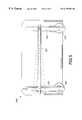
- FIG. 5is a schematic side view of the support tray and elevators of the sheet feeder
- FIG. 6is a schematic side view illustrating the ranges of the stack height sensor according to the invention.
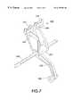
- FIG. 7is a perspective view of the stack height sensor according to the invention.
- FIGS. 8 and 9are perspective views of a unidirectional rotating drive mechanism for the feed head and the stack height sensor according to the invention.
- FIG. 10is a flow chart of a sheet acquisition time adjusting control method according to the invention.
- FIG. 1is a schematic of an image forming apparatus 100 of an exemplary embodiment of the invention.
- the image forming apparatus 100has an image forming engine 110 for fixing an image to a sheet of recording media.
- a user interface 120allows a user of the image forming apparatus 100 to input a print request, including a total number of sheets to be printed. The user can also input the characteristics of the sheets to be printed. The characteristics may include the sheet basis weight, the size of the sheet, and the coating on the sheet.
- a sheet feeder 200separates a sheet from the top of a stack, acquires the separated sheet and delivers the separated sheet to the image forming engine 110 .
- a control circuit 300controls the sheet acquisition time based on a running average and standard deviation of a predetermined number of previously successfully fed sheets. The control circuit 300 also adjusts the position of the stack and controls the take away nip rolls that receive the acquired sheet and deliver the sheet to the image forming engine 110 .
- FIG. 2is a side elevation schematic view of one exemplary embodiment of the sheet feeder 200 and control circuit 300 according to the invention.
- the sheet feeder 200includes a support tray 201 that is tiltable and self adjusting to accommodate sheets having various characteristics.
- a stack 202 of sheetsis supported on the sheet support tray 201 so that the leading edge 203 of the stack 202 abuts a registration wall 204 .
- Sheet fluffers 205 and 206blow air against the stack 202 to separate the top sheet 207 from the stack 202 .
- the trailing edge sheet fluffer 205blows air at a trailing edge 208 of the stack 202 .
- Two side edge sheet fluffers 206only one of which can be seen in FIG. 2, blow air at opposing sides of the stack 202 .
- a feed head assembly 209includes a housing 210 that supports a translating vacuum feed head 211 for movement toward and away from the pair of take away nip rolls 212 .
- the take away nip rolls 212are driven by a stepper motor 213 .
- a sheet acquisition sensor 216 in the translating vacuum feed head 211detects acquisition of the top sheet 207 by an acquisition surface 215 of the translating vacuum feed head 211 .
- Vacuum pressureis applied to the translating vacuum feed head 211 by a blower assembly 217 through a vacuum manifold 218 .
- the blower assembly 217includes a variable speed brushless DC motor.
- Airis supplied from the blower assembly 217 to a positive pressure plenum 250 .
- Airis supplied from the positive pressure plenum 250 to the sheet fluffers 205 and 206 through fluffer manifolds 219 and 220 , respectively.
- Airis also supplied from the positive pressure plenum 250 to an air knife 251 .
- the airis supplied from the positive pressure plenum 250 to an air knife plenum 253 through an air knife manifold 252 .
- the air knife 251separates any secondarily acquired sheets from the top sheet 207 acquired by the acquisition surface 215 . Secondarily acquired sheets are sheets that stick to the top sheet 207 acquired by the acquisition surface 215 .
- the vacuum manifold 218is opened and closed by a vacuum manifold valve 221 . Opening the vacuum manifold valve 221 allows vacuum pressure to be applied to the translating vacuum feed head 211 by the blower assembly 217 .
- the vacuum manifold valve 221is opened by a stepper motor.
- a vacuum manifold valve sensor 224detects the opening of the vacuum manifold valve 221 .
- a signalis sent to the control circuit 300 when the vacuum manifold valve sensor 224 detects that the vacuum manifold valve 221 has been opened.
- the housing 210 of the feed head assembly 209also supports a unidirectional rotating drive mechanism 225 for the translating vacuum feed head 211 , a stack height sensor 226 and a lead edge attitude sensor 227 .
- the stack height sensor 226is also driven by the unidirectional rotating drive mechanism 225 to contact the top of the stack 202 after a trailing edge of the top sheet 207 that has been fed by the translating vacuum feed head 211 to the take away nip rolls 212 passes the stack height sensor 226 .
- the stack height sensor 226 and the lead edge attitude sensor 227are used to control the position of the support tray 201 .
- the control circuit 300includes a controller 310 having a memory 320 .
- the controller 310receives signals from the vacuum manifold valve sensor 224 and the sheet acquisition sensor 216 in the feed head assembly 209 and controls the blower assembly 217 in response to the signals.
- the controller 310also receives signals from the vacuum manifold valve sensor 224 and the lead edge attitude sensor 227 and controls the blower assembly 217 in response to the signals.
- the controller 310also receives a signal from the stack height sensor 226 and the lead edge attitude sensor 227 to control the position of the support tray 201 in response to the signals.
- the controller 310also controls the stepper motor 213 that drives the take away nip rolls 212 by executing a control program stored in the memory 320 .
- FIG. 3is a schematic side elevation sectional view of the translating vacuum feed head 211 .
- the translating vacuum feed head 211includes a plenum 214 and the acquisition surface 215 .
- the plenum 214is formed of an injection molded plastic.
- the plenum 214includes a port 228 formed in one side which is connected to the vacuum manifold 218 .
- the junction of the port 228 and the vacuum manifold 218includes a sliding seal (not shown) that allows the translating vacuum feed head 211 to move toward and away from the take away nip rolls 212 while maintaining the connection to the vacuum manifold 218 .
- a pressure measured at the junction of the port 228 and the vacuum manifold 218 when a sheet is acquiredis defined as a sealed port pressure.
- the sheet acquisition sensor 216is mounted in the plenum 214 near the port 228 and the lead edge attitude sensor 227 is mounted at a forward side of the plenum 214 .
- Sheet acquisitioncan be detected by either the sheet acquisition sensor 216 or the lead edge attitude sensor 227 .
- the acquisition surface 215includes a corrugation plate 256 .
- the corrugation plate 256includes a plurality of corrugating ribs 255 , a plurality of apertures 229 and a plurality of cut-outs 230 where the corrugation plate 256 will surround the take away nip rolls 212 when the translating vacuum feed head 211 is in the forward position.
- the acquisition surface 215is an elastomer as acquired sheets are corrugated to improve sheet separation and are then frictionally moved by the corrugation plate 256 as the vacuum feed head 211 is driven forward by the unidirectional rotating drive mechanism 225 .
- the corrugation plate 256may be replaced if the acquisition surface 215 becomes worm.
- the corrugation plate 256may also be replaced by a different corrugation plate having a different number of apertures and/or apertures of a different size depending on the characteristics of the sheets to be fed.
- the sheet acquisition sensor 216detects the acquisition of the top sheet 207 by the translating vacuum feed head 211 .
- the sheet acquisition sensor 216detects a deflection of the acquisition surface 215 .
- the top sheet 207covers the apertures 229 in the corrugation plate 256 .
- the vacuum pressurewill cause the corrugation plate 256 to bow upwardly into the plenum 214 .
- the sheet acquisition sensor 216detects the deflection of the corrugation plate 256 . The amount of deflection is dependent on the characteristics of the sheet.
- the amounts of deflection produced when sheets of varying characteristics are acquired by the translating vacuum feed head 211are experimentally determined and the results are stored in the memory 320 of the controller 310 .
- the sheet acquisition sensor 216sends a signal to the controller 310 indicating the deflection of the corrugation plate 256 .
- the controller 310determines that the top sheet 207 has been acquired by the translating vacuum feed head 211 .
- the sheet acquisition sensor 216detects the sealed port pressure produced when the translating vacuum feed head 211 acquires the top sheet 207 .
- the apertures 229 in the corrugation plate 256are covered.
- the sealed port pressure produced when sheets of varying characteristics are acquired by the translating vacuum feed head 211are experimentally determined and the results are stored in the memory 320 of the controller 310 .
- the sheet acquisition sensor 216sends a signal to the controller 310 indicating the sealed port pressure.
- the controller 310determines that the top sheet 207 has been acquired by the translating vacuum feed head 211 .
- the lead edge attitude sensor 227detects sheet acquisition.
- the lead edge attitude sensor 227may include a position sensitive device or multiple sensors with different focal lengths.
- the lead edge attitude sensor 227is an infrared LED with 4 detectors which determine the location of the lead edge of the top sheet 207 within a range of 0 mm-3 mm, 3 mm-6 mm, 6 mm-9 mm or greater than 9 mm from the acquisition surface 215 .
- the lead edge attitude sensor 227sends a signal to the controller 310 . When the signal indicates that the lead edge of the top sheet 207 is in the 0-3 mm range, the controller 310 determines that the top sheet 207 has been acquired.
- the stack 202is placed on the support tray 201 .
- the support tray 201is supported at both ends by elevators 231 and 232 .
- Each elevator 231 and 232is driven by an independent motors 233 and 234 , respectively.
- the motors 233 and 234can be stepper motors or brushless DC motors.
- the support tray 201can be raised or lowered and/or tilted by driving one or both of the independent motors 233 and 234 .
- the controller 310drives the independent motors 233 and 234 to raise the support tray 201 to an initial stack height.
- Stack heightis defined as the distance from the top of the stack 202 to the acquisition surface 215 .
- the initial stack heightis dependent on the sheet characteristics, including the sheet size and sheet basis weight, as input into the user interface. Heavyweight sheets are more difficult to acquire than lightweight sheets and are more prone to misfeed or late acquisition. Accordingly, a stack of heavyweight sheets is initially placed in a range closer to the acquisition surface 215 . Lightweight sheets are easier to acquire and are more prone to multifeed. Accordingly, a stack of lightweight sheets is placed in a range further from the acquisition surface 215 .
- the initial stack heights for particular sheets of varying sheet basis weightsare determined experimentally and stored in the memory 320 . Signals are sent from the stack height sensor 226 and the lead edge attitude sensor 227 to the controller 310 . The controller 310 drives the independent motors 233 and 234 to set the initial stack height.
- the stack height sensorincludes a stack height sensor arm 235 which is pivotably mounted in the housing 210 of the feed head assembly 209 by a shaft 236 passing through a journal 237 at the top of the stack height sensor arm 235 .
- the stack height sensor arm 235is biased by a spring (not shown) into contact with the top of the stack 202 .
- the housing 210 of the feed head assembly 209is not shown in FIGS. 6-9 so that the stack height sensor 226 may be more clearly seen.
- a roller 238 at the end of the stack height sensor arm 235is movable into and out of contact with the top of the stack 202 . As shown in FIG.
- pair of flags 239 and 240extend from the journal 237 of the stack height sensor arm 235 .
- the position of each flag 239 and 240is detected by transmissive sensors 241 and 242 , respectively.
- the positions of the flags 239 and 240as sensed by the transmissive sensors 241 and 242 , respectively, determines the stack height.
- the stack height sensor 226determines the stack height in one of four ranges: greater than 15 mm, 15 mm 12.5 mm, 12.5 mm-10 mm, and less than 10 mm.
- the stack height sensor 226 and the lead edge attitude sensor 227send signals indicating the stack height to the controller 310 as the controller 310 drives the independent motors 233 and 234 to raise the support tray 201 .
- the controller 310stops driving the independent motors 233 and 234 .
- the blower assembly 217is activated.
- the trail edge sheet fluffer 205 , the side edge sheet fluffers 206 , and the air knife 251are supplied with air from the blower assembly 217 to separate the top sheet 207 from the top of the stack 202 .
- the translating vacuum feed head 211is supplied with a vacuum pressure by the blower assembly 217 .
- the top sheet 207is acquired by the translating vacuum feed head 211 .
- the translating vacuum feed head 211is supported at each comer by a ball bearing or low friction roller 243 in a slide 244 of the housing (not shown).
- the translating vacuum feed head 211is driven forward and returned to a home position by the unidirectional rotating drive mechanism 225 .
- a sensor 254detects the translating vacuum feed head 211 when the translating vacuum feed head 211 is in the home position.
- the unidirectional rotating drive mechanism 225includes two slider-cranks 245 , only one of which can be seen in FIGS. 8 and 9.
- the slider-cranks 245are mounted on shafts of a unidirectional double shaft stepper motor 246 .
- the translating vacuum feed head 211is driven forward 20 mm and returned 20 mm back to the home position. This includes 5 mm overtravel to account for paper loading tolerance and misregistration.
- the unidirectional rotating drive mechanism 225drives the translating vacuum feed head 211 forward with a velocity profile which delivers the acquired sheet to the take away nip rolls 212 at a speed of, for example, approximately 430 mm/s.
- the top sheet 207is delivered to take away nip rolls 212 .
- the take away nip rolls 212are driven by the stepper motor 213 which is controlled by the controller 310 . Once the top sheet 207 is delivered to the take away nip rolls 212 , the controller 310 increases the speed of the stepper motor 213 to accelerate the top sheet 207 to match the transport speed of the image forming engine 110 .
- the stack height sensor arm 235includes a cam follower 247 .
- a cam 248is mounted to a shaft of the double shaft stepper motor 246 .
- the cam 248includes a portion that engages the cam follower 247 on the stack height sensor arm 235 to lift the roller 238 at the end of the stack height sensor arm 235 out of contact with the top of the stack 202 .
- the cam 248includes another portion which allows the spring biased stack height sensor arm 235 to drop the roller 238 back into contact with the top of the stack 202 .
- the translating vacuum feed head 211After the translating vacuum feed head 211 has delivered the top sheet 207 to the take away nip rolls 212 , the translating vacuum feed head 211 dwells in the forward position to allow the trailing edge of the top sheet 207 to pass the roller 238 , which has been lifted off of the top of the stack 202 by the cam 248 . Just before the trailing edge of the top sheet 207 passes the roller 238 of the stack height sensor 226 , the dwell ends and the unidirectional drive 225 begins to return the translating vacuum feed head 211 to the home position. Before the translating vacuum feed head 211 reaches the home position, the cam 248 rotates to a position which allows the roller 238 to contact the stack 202 .
- the roller 238is in contact with the stack 202 for 25 ms.
- the transmissive sensors 241 and 242send signals to the controller 310 indicating the stack height.
- a signal from the lead edge attitude sensor 227is also sent to the controller 310 .
- the controller 310adjusts the position of the support tray 201 in response to the signals by driving the independent motors 233 and 234 to maintain the desired stack height and the desired position indicated by the lead edge attitude sensor 227 .
- the cam 248lifts the roller 238 off the stack 202 .
- Sheet acquisition timeis defined as the time between the opening of the vacuum manifold valve 221 as sensed by the vacuum manifold valve sensor 224 and acquisition of the top sheet 207 by the acquisition surface 215 of the translating vacuum feed head 211 as detected by the sheet acquisition sensor 216 or the lead edge attitude sensor 227 .
- Performance of the sheet feeder 200may be improved by dynamically adjusting the sheet acquisition time during feeding by adjusting the pressures of the trailing edge sheet fluffer 205 , the side edge sheet fluffers 206 , the air knife 251 and the vacuum pressure of the translating vacuum feed head 211 .
- the sheet feeder 200acquires individual sheets, using positive and negative air pressures supplied from the blower assembly 217 to the sheet fluffers 205 and 206 and to the translating vacuum feed head 211 , respectively, from the top of the stack 202 and transports them forward to the take away nip rolls 212 .
- independent variables in the sheet feeder 200which affect the sheet acquisition time are sheet fluffer pressures and vacuum pressure.
- fluffer pressureincreases, the sheets on the top of the stack 202 become more separated, with the top most sheets being lifted closer to the translating vacuum feed head 211 , thus reducing sheet acquisition time.
- the fluffing pressureincreases, the risk of multifeed also increases.
- the fluffing pressuredecreases, the sheets on the top of the stack 202 become less separated from the top of the stack 202 , thus increasing the sheet acquisition time.
- the fluffing pressuredecreases, the risk of misfeed and/or late acquisition increases.
- the sheet acquisition timeis also a function of the sheet size and sheet basis weight. Predetermined sheet acquisition times for sheets of a particular size and sheet basis weight are experimentally determined and stored in the memory 320 .
- the blower assembly 217can be dynamically adjusted during sheet feeding to dynamically control sheet acquisition time by using sheet characteristic information input by the operator into the user interface 120 and information from the vacuum manifold valve sensor 224 and the sheet acquisition sensor 216 or the lead edge attitude sensor 227 .
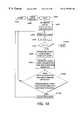
- FIG. 10is a flow chart outlining one exemplary embodiment of a sheet acquisition time adjusting control method according to this invention.
- step S 100control continues to step S 200 , where a user enters a print request command into the user interface.
- the print request commandincludes a total number T of sheets to be printed.
- step S 400the initial stack height and the initial pressure of the sheet fluffers and air knife, and the initial vacuum pressure applied to the translating vacuum feed head are determined.
- the initial stack height and pressuresare set according to the sheet characteristics which are input by the operator or sensed automatically by sensors in the image forming apparatus 100 .
- the initial stack heightis set by adjusting the distance between the top of the paper stack and the sheet acquisition surface.
- the initial pressuresare set according to the sheet characteristics by referring to a table of initial pressures which are experimentally determined for the particular sheet characteristics or are set by an equation which is experimentally determined according to the sheet characteristics.
- the table or equation of initial pressuresis stored in a memory. The control then continues to step S 500 .
- step S 500a first sheet is fed. Then, in step S 600 , the counter value N is incremented by one. Next, in step S 700 , the incremented value is compared to the total number T of sheets requested. If the incremented value is equal to the total number T of sheets requested, control jumps to step S 1200 . Otherwise, if the incremented value is less than the total number of sheets requested, the control continues to step S 800 .
- step S 800the sheet acquisition time is determined. As previously described, the sheet acquisition time is determined as the time from applying the vacuum pressure to the sheet acquisition surface to acquiring the top sheet.
- step S 900the mean sheet acquisition time and standard deviation for a predetermined number of previously successfully fed sheets are determined.
- the predetermined numberis 50. Until the number of sheets actually fed exceeds the predetermined number, the mean sheet acquisition time and standard deviation for all sheets successfully fed is determined.
- step S 1000the mean sheet acquisition time and the standard deviation are compared to predetermined sheet acquisition times and standard deviations. If the mean sheet acquisition time and standard deviation for the predetermined number of previously successfully fed sheets is within the predetermined range, control jumps back to step S 500 . Otherwise, if the mean sheet acquisition time and standard deviation for the predetermined number of previously successfully fed sheets is above or below the predetermined range, control continues to step S 100 . In step S 1100 the blower assembly 217 is adjusted.
- the sheet fluffer pressures and the vacuum pressure applied to the sheet acquisition surfaceare increased to decrease sheet acquisition time. If the sheet acquisition time is shorter than the predetermined value, the sheet fluffer pressures and the vacuum pressure applied to the sheet acquisition surface are decreased to increase sheet acquisition time.
- step S 1200once the number of sheets actually fed equals the predetermined number T specified in the print request command, the control ends.
- control circuit 300 shown in FIGS. 1 and 2can be implemented as portions of a suitably programmed general purpose computer.
- the control circuitcan be implemented as physically distinct hardware circuits within an ASIC, or using a FPGA, a PDL, a PLA or a PAL, or using discrete logic elements or discrete circuit elements.
- the particular form the control circuit shown in FIGS. 1 and 2 will takeis a design choice and will be obvious and predictable to those skilled in the art.
- the sheet acquisition time control methodcan be implemented on a programmed general purpose computer.
- the sheet acquisition time control sequencecan also be implemented on a special purpose computer, a programmed microprocessor or microcontroller and peripheral integrated circuit elements, an ASIC or other integrated circuit, a digital signal processor, a hardwired electronic or log circuit such as a discrete element circuit, a programmable logic device such as a PLD, PLA, FPGA or PAL, or the like.
- any device capable of implementing a finite state machinethat is in turn capable of implementing the flow diagram of FIG. 10, can be used to implement the sheet acquisition time control method.
- the memory 320may be implemented using a ROM. However, the memory 320 can also be implemented using a PROM, an EPROM, an optical ROM disk, such as a CD-ROM or DVD-ROM, and disk drive or the like.
Landscapes
- Engineering & Computer Science (AREA)
- Mechanical Engineering (AREA)
- Sheets, Magazines, And Separation Thereof (AREA)
Abstract
Description
Claims (19)
Priority Applications (5)
| Application Number | Priority Date | Filing Date | Title |
|---|---|---|---|
| US09/416,417US6279896B1 (en) | 1999-10-12 | 1999-10-12 | Systems and methods for dynamically setting air system pressures based on real time sheet acquisition time data |
| JP2000309423AJP4716552B2 (en) | 1999-10-12 | 2000-10-10 | Sheet feeder |
| DE60027104TDE60027104T2 (en) | 1999-10-12 | 2000-10-10 | Method for feeding sheets |
| EP00308907AEP1092659B1 (en) | 1999-10-12 | 2000-10-10 | Method of feeding sheets |
| BRPI0004784-8ABR0004784B1 (en) | 1999-10-12 | 2000-10-11 | Sheet feeder and method of sheet feeding. |
Applications Claiming Priority (1)
| Application Number | Priority Date | Filing Date | Title |
|---|---|---|---|
| US09/416,417US6279896B1 (en) | 1999-10-12 | 1999-10-12 | Systems and methods for dynamically setting air system pressures based on real time sheet acquisition time data |
Publications (1)
| Publication Number | Publication Date |
|---|---|
| US6279896B1true US6279896B1 (en) | 2001-08-28 |
Family
ID=23649894
Family Applications (1)
| Application Number | Title | Priority Date | Filing Date |
|---|---|---|---|
| US09/416,417Expired - LifetimeUS6279896B1 (en) | 1999-10-12 | 1999-10-12 | Systems and methods for dynamically setting air system pressures based on real time sheet acquisition time data |
Country Status (5)
| Country | Link |
|---|---|
| US (1) | US6279896B1 (en) |
| EP (1) | EP1092659B1 (en) |
| JP (1) | JP4716552B2 (en) |
| BR (1) | BR0004784B1 (en) |
| DE (1) | DE60027104T2 (en) |
Cited By (27)
| Publication number | Priority date | Publication date | Assignee | Title |
|---|---|---|---|---|
| US20020074714A1 (en)* | 2000-12-18 | 2002-06-20 | Xerox Corporation | Reproduction machine having a safe tiltable paper tray |
| US6609708B2 (en)* | 1998-12-23 | 2003-08-26 | Xerox Corporation | Vacuum corrugation shuttle feed device for high capacity feeder |
| US20030172795A1 (en)* | 2002-03-15 | 2003-09-18 | Lotfi Belkhir | Page turning apparatus with a vacuum plenum and an adaptive air fluffer |
| US20040047009A1 (en)* | 2002-09-10 | 2004-03-11 | Taylor Thomas N. | Automated page turning apparatus to assist in viewing pages of a document |
| US6726200B2 (en)* | 2000-10-26 | 2004-04-27 | Heidelberger Druckmaschinen Ag | Apparatus and method for adjusting an air flow influencing a sheet transport in a printing machine |
| US20040163028A1 (en)* | 2003-02-18 | 2004-08-19 | Olarig Sompong P. | Technique for implementing chipkill in a memory system |
| US20060197273A1 (en)* | 2005-03-04 | 2006-09-07 | Powell Wade A | Media stack measurement and method |
| US20060197274A1 (en)* | 2005-03-04 | 2006-09-07 | Powell Wade A | Printing system and method |
| US20070063418A1 (en)* | 2005-09-20 | 2007-03-22 | Xerox Corporation | Integrated vacuum slide feeder |
| US20070228639A1 (en)* | 2006-04-03 | 2007-10-04 | Canon Kabushiki Kaisha | Sheet feeding apparatus and image forming apparatus |
| US20070228640A1 (en)* | 2006-04-03 | 2007-10-04 | Canon Kabushiki Kaisha | Image forming apparatus |
| US20080316551A1 (en)* | 2002-09-10 | 2008-12-25 | Kirtas Technologies, Inc. | Automated page turning apparatus to assist in viewing pages of a document |
| US20090057986A1 (en)* | 2007-08-28 | 2009-03-05 | Canon Kabushiki Kaisha | Sheet feeding apparatus and image forming apparatus |
| US20090057982A1 (en)* | 2007-08-29 | 2009-03-05 | Kabushiki Kaisha Toshiba | Sheet take-out apparatus |
| US20090057990A1 (en)* | 2004-09-13 | 2009-03-05 | Satoshi Ueda | Sheet-supplying device |
| US20090180085A1 (en)* | 2008-01-15 | 2009-07-16 | Kirtas Technologies, Inc. | System and method for large format imaging |
| US20090322013A1 (en)* | 2008-06-25 | 2009-12-31 | Xerox Corporation | Media stack sheet fluffer method and apparatus, and a media processing device arranged with the same |
| US20100032892A1 (en)* | 2008-08-07 | 2010-02-11 | Xerox Corporation | Method and apparatus for fluff management in an image production device |
| US20100133745A1 (en)* | 2008-12-02 | 2010-06-03 | Hiroyuki Ikeuchi | Remaining sheet volume detecting apparatus and image forming apparatus |
| US20100171804A1 (en)* | 2009-01-05 | 2010-07-08 | Kabushiki Kaisha Toshiba | Image recording apparatus |
| US20100213666A1 (en)* | 2009-02-24 | 2010-08-26 | Xerox Corporation | Media transport device with vacuum-controlled positioning |
| US20100298971A1 (en)* | 2008-08-07 | 2010-11-25 | Xerox Corporation | Method and apparatus for feeding sheets of media from a media stack in an image production device |
| US20110062652A1 (en)* | 2009-09-15 | 2011-03-17 | Xerox Corporation | Vacuum level switch for a vacuum corrugated feeder |
| US20110163492A1 (en)* | 2010-01-05 | 2011-07-07 | Konica Minolta Business Technologies, Inc. | Sheet feeding apparatus and image forming system |
| US20120205857A1 (en)* | 2011-02-14 | 2012-08-16 | Xerox Corporation | Method and apparatus for feeding media sheets in an image production device |
| US20120280445A1 (en)* | 2011-05-05 | 2012-11-08 | Xerox Corporation | Method and apparatus for feeding media sheets in an image production device |
| US20160167905A1 (en)* | 2014-12-10 | 2016-06-16 | Nisca Corporation | Sheet feeder |
Families Citing this family (4)
| Publication number | Priority date | Publication date | Assignee | Title |
|---|---|---|---|---|
| US7472902B2 (en)* | 2005-09-20 | 2009-01-06 | Xerox Corporation | System and method for improving top sheet acquisition in a printing machine |
| JP2007308295A (en)* | 2006-05-22 | 2007-11-29 | Canon Inc | Sheet feeding apparatus and image forming apparatus |
| JP6378476B2 (en)* | 2013-10-03 | 2018-08-22 | 三菱重工機械システム株式会社 | Paper feeding device and paper feeding method |
| US10233042B1 (en)* | 2018-01-22 | 2019-03-19 | Xerox Corporation | Top vacuum corrugation feeder with adjustable fluffer nozzles for enhanced feeding of specialty sheets |
Citations (8)
| Publication number | Priority date | Publication date | Assignee | Title |
|---|---|---|---|---|
| DE2835385A1 (en)* | 1977-11-28 | 1979-05-31 | Polygraph Leipzig | SWITCH BASE |
| US5184813A (en)* | 1991-03-13 | 1993-02-09 | Koenig & Bauer Aktiengesellschaft | Separating jet blast air control assembly |
| US5290023A (en)* | 1991-08-23 | 1994-03-01 | Ryobi Limited | Sheet feeder for sheet-fed press |
| US5645274A (en)* | 1993-09-22 | 1997-07-08 | Canon Kabushiki Kaisha | Sheet supply apparatus |
| US5893554A (en)* | 1996-09-13 | 1999-04-13 | Sharp Kabushiki Kaisha | Sheet feeding apparatus |
| US5988624A (en)* | 1995-11-21 | 1999-11-23 | Sharp Kabushiki Kaisha | Paper feeding device |
| US6082728A (en)* | 1993-10-01 | 2000-07-04 | Canon Kabushiki Kaisha | Sheet feeding apparatus |
| US6123330A (en)* | 1995-12-02 | 2000-09-26 | Siemens Aktiengesellschaft | Method of feeding flat mail for separation by suction of material input |
Family Cites Families (7)
| Publication number | Priority date | Publication date | Assignee | Title |
|---|---|---|---|---|
| JPH01187137A (en)* | 1988-01-22 | 1989-07-26 | Hitachi Ltd | Paper feeder |
| JPH01321228A (en)* | 1988-06-23 | 1989-12-27 | Seiko Epson Corp | sheet feeding device |
| JP3058237B2 (en)* | 1993-10-28 | 2000-07-04 | キヤノン株式会社 | Sheet feeding apparatus and image forming apparatus |
| JPH0958902A (en)* | 1995-08-29 | 1997-03-04 | Sharp Corp | Sheet feeding device that uses air |
| DE19714204C2 (en)* | 1997-04-07 | 2000-08-31 | Roland Man Druckmasch | Device for regulating the blown air on a sheet feeder |
| US6015146A (en)* | 1998-01-08 | 2000-01-18 | Xerox Corporation | Curl sensitive bottom vacuum corrugation feeder |
| US6186492B1 (en)* | 1998-12-23 | 2001-02-13 | Xerox Corporation | Adjusting air system pressures stack height and lead edge gap in high capacity feeder |
- 1999
- 1999-10-12USUS09/416,417patent/US6279896B1/ennot_activeExpired - Lifetime
- 2000
- 2000-10-10DEDE60027104Tpatent/DE60027104T2/ennot_activeExpired - Lifetime
- 2000-10-10JPJP2000309423Apatent/JP4716552B2/ennot_activeExpired - Fee Related
- 2000-10-10EPEP00308907Apatent/EP1092659B1/ennot_activeExpired - Lifetime
- 2000-10-11BRBRPI0004784-8Apatent/BR0004784B1/ennot_activeIP Right Cessation
Patent Citations (8)
| Publication number | Priority date | Publication date | Assignee | Title |
|---|---|---|---|---|
| DE2835385A1 (en)* | 1977-11-28 | 1979-05-31 | Polygraph Leipzig | SWITCH BASE |
| US5184813A (en)* | 1991-03-13 | 1993-02-09 | Koenig & Bauer Aktiengesellschaft | Separating jet blast air control assembly |
| US5290023A (en)* | 1991-08-23 | 1994-03-01 | Ryobi Limited | Sheet feeder for sheet-fed press |
| US5645274A (en)* | 1993-09-22 | 1997-07-08 | Canon Kabushiki Kaisha | Sheet supply apparatus |
| US6082728A (en)* | 1993-10-01 | 2000-07-04 | Canon Kabushiki Kaisha | Sheet feeding apparatus |
| US5988624A (en)* | 1995-11-21 | 1999-11-23 | Sharp Kabushiki Kaisha | Paper feeding device |
| US6123330A (en)* | 1995-12-02 | 2000-09-26 | Siemens Aktiengesellschaft | Method of feeding flat mail for separation by suction of material input |
| US5893554A (en)* | 1996-09-13 | 1999-04-13 | Sharp Kabushiki Kaisha | Sheet feeding apparatus |
Cited By (53)
| Publication number | Priority date | Publication date | Assignee | Title |
|---|---|---|---|---|
| US6609708B2 (en)* | 1998-12-23 | 2003-08-26 | Xerox Corporation | Vacuum corrugation shuttle feed device for high capacity feeder |
| US6726200B2 (en)* | 2000-10-26 | 2004-04-27 | Heidelberger Druckmaschinen Ag | Apparatus and method for adjusting an air flow influencing a sheet transport in a printing machine |
| US6460846B2 (en)* | 2000-12-18 | 2002-10-08 | Xerox Corporation | Reproduction machine having a safe tiltable paper tray |
| US20020074714A1 (en)* | 2000-12-18 | 2002-06-20 | Xerox Corporation | Reproduction machine having a safe tiltable paper tray |
| US7595915B2 (en)* | 2002-03-15 | 2009-09-29 | Kirtas Technologies, Inc. | Page turning apparatus with a vacuum plenum and an adaptive air fluffer |
| US20030172795A1 (en)* | 2002-03-15 | 2003-09-18 | Lotfi Belkhir | Page turning apparatus with a vacuum plenum and an adaptive air fluffer |
| US20080316551A1 (en)* | 2002-09-10 | 2008-12-25 | Kirtas Technologies, Inc. | Automated page turning apparatus to assist in viewing pages of a document |
| US20040047009A1 (en)* | 2002-09-10 | 2004-03-11 | Taylor Thomas N. | Automated page turning apparatus to assist in viewing pages of a document |
| US7557965B2 (en) | 2002-09-10 | 2009-07-07 | Kirtas Technologies, Inc. | Automated page turning apparatus to assist in viewing pages of a document |
| US20040163028A1 (en)* | 2003-02-18 | 2004-08-19 | Olarig Sompong P. | Technique for implementing chipkill in a memory system |
| US20120153560A1 (en)* | 2004-09-13 | 2012-06-21 | Satoshi Ueda | Sheet-Supplying Device |
| US20100164165A1 (en)* | 2004-09-13 | 2010-07-01 | Satoshi Ueda | Sheet-Supplying Device |
| US8490965B2 (en) | 2004-09-13 | 2013-07-23 | Ricoh Company, Ltd. | Sheet-supplying device |
| US8403319B2 (en)* | 2004-09-13 | 2013-03-26 | Ricoh Company, Ltd. | Sheet-supplying device |
| US20090057990A1 (en)* | 2004-09-13 | 2009-03-05 | Satoshi Ueda | Sheet-supplying device |
| US7841591B2 (en)* | 2004-09-13 | 2010-11-30 | Ricoh Comapny, Ltd. | Sheet-supplying device |
| US7413182B2 (en) | 2005-03-04 | 2008-08-19 | Hewlett-Packard Development Company, L.P. | Printing system and method |
| US7431286B2 (en) | 2005-03-04 | 2008-10-07 | Hewlett-Packard Development Company, L.P. | Media stack measurement and method |
| US20060197273A1 (en)* | 2005-03-04 | 2006-09-07 | Powell Wade A | Media stack measurement and method |
| US20060197274A1 (en)* | 2005-03-04 | 2006-09-07 | Powell Wade A | Printing system and method |
| US7258336B2 (en)* | 2005-09-20 | 2007-08-21 | Xerox Corporation | Integrated vacuum slide feeder |
| US20070063418A1 (en)* | 2005-09-20 | 2007-03-22 | Xerox Corporation | Integrated vacuum slide feeder |
| US7744081B2 (en)* | 2006-04-03 | 2010-06-29 | Canon Kabushiki Kaisha | Image forming apparatus |
| US7591459B2 (en)* | 2006-04-03 | 2009-09-22 | Canon Kabushiki Kaisha | Sheet feeding apparatus and image forming apparatus |
| US20070228640A1 (en)* | 2006-04-03 | 2007-10-04 | Canon Kabushiki Kaisha | Image forming apparatus |
| US20070228639A1 (en)* | 2006-04-03 | 2007-10-04 | Canon Kabushiki Kaisha | Sheet feeding apparatus and image forming apparatus |
| US20090057986A1 (en)* | 2007-08-28 | 2009-03-05 | Canon Kabushiki Kaisha | Sheet feeding apparatus and image forming apparatus |
| US8177222B2 (en)* | 2007-08-28 | 2012-05-15 | Canon Kabushiki Kaisha | Sheet feeding apparatus and image forming apparatus |
| US8235378B2 (en)* | 2007-08-29 | 2012-08-07 | Kabushiki Kaisha Toshiba | Sheet take-out apparatus |
| US20090057982A1 (en)* | 2007-08-29 | 2009-03-05 | Kabushiki Kaisha Toshiba | Sheet take-out apparatus |
| US20090180085A1 (en)* | 2008-01-15 | 2009-07-16 | Kirtas Technologies, Inc. | System and method for large format imaging |
| US7819397B2 (en) | 2008-06-25 | 2010-10-26 | Xerox Corporation | Media stack sheet fluffer method and apparatus, and a media processing device arranged with the same |
| US20090322013A1 (en)* | 2008-06-25 | 2009-12-31 | Xerox Corporation | Media stack sheet fluffer method and apparatus, and a media processing device arranged with the same |
| US20100298971A1 (en)* | 2008-08-07 | 2010-11-25 | Xerox Corporation | Method and apparatus for feeding sheets of media from a media stack in an image production device |
| US7770884B2 (en)* | 2008-08-07 | 2010-08-10 | Xerox Corporation | Method and apparatus for fluff management in an image production device |
| US8485517B2 (en) | 2008-08-07 | 2013-07-16 | Xerox Corporation | Method and apparatus for feeding sheets of media from a media stack in an image production device |
| US20100032892A1 (en)* | 2008-08-07 | 2010-02-11 | Xerox Corporation | Method and apparatus for fluff management in an image production device |
| US8025284B2 (en)* | 2008-12-02 | 2011-09-27 | Fuji Xerox Co., Ltd. | Remaining sheet volume detecting apparatus and image forming apparatus |
| US20100133745A1 (en)* | 2008-12-02 | 2010-06-03 | Hiroyuki Ikeuchi | Remaining sheet volume detecting apparatus and image forming apparatus |
| US20100171804A1 (en)* | 2009-01-05 | 2010-07-08 | Kabushiki Kaisha Toshiba | Image recording apparatus |
| US20100213666A1 (en)* | 2009-02-24 | 2010-08-26 | Xerox Corporation | Media transport device with vacuum-controlled positioning |
| US7988150B2 (en)* | 2009-02-24 | 2011-08-02 | Xerox Corporation | Media transport device with vacuum-controlled positioning |
| US8042799B2 (en)* | 2009-09-15 | 2011-10-25 | Xerox Corporation | Vacuum level switch for a vacuum corrugated feeder |
| US20110062652A1 (en)* | 2009-09-15 | 2011-03-17 | Xerox Corporation | Vacuum level switch for a vacuum corrugated feeder |
| US8444138B2 (en)* | 2010-01-05 | 2013-05-21 | Konica Minolta Business Technologies, Inc. | Sheet feeding apparatus and image forming system with air blower device |
| US20110163492A1 (en)* | 2010-01-05 | 2011-07-07 | Konica Minolta Business Technologies, Inc. | Sheet feeding apparatus and image forming system |
| US20120205857A1 (en)* | 2011-02-14 | 2012-08-16 | Xerox Corporation | Method and apparatus for feeding media sheets in an image production device |
| US9067439B2 (en)* | 2011-02-14 | 2015-06-30 | Xerox Corporation | Method and apparatus for feeding media sheets in an image production device |
| US20120280445A1 (en)* | 2011-05-05 | 2012-11-08 | Xerox Corporation | Method and apparatus for feeding media sheets in an image production device |
| US8317185B1 (en)* | 2011-05-05 | 2012-11-27 | Xerox Corporation | Method and apparatus for feeding media sheets in an image production device |
| JP2012232846A (en)* | 2011-05-05 | 2012-11-29 | Xerox Corp | Method and apparatus for feeding media sheet in image production apparatus |
| US20160167905A1 (en)* | 2014-12-10 | 2016-06-16 | Nisca Corporation | Sheet feeder |
| US9604805B2 (en)* | 2014-12-10 | 2017-03-28 | Nisca Corporation | Sheet feeder |
Also Published As
| Publication number | Publication date |
|---|---|
| JP4716552B2 (en) | 2011-07-06 |
| JP2001151361A (en) | 2001-06-05 |
| BR0004784A (en) | 2001-05-29 |
| EP1092659B1 (en) | 2006-04-05 |
| EP1092659A2 (en) | 2001-04-18 |
| BR0004784B1 (en) | 2009-01-13 |
| DE60027104D1 (en) | 2006-05-18 |
| EP1092659A3 (en) | 2002-05-08 |
| DE60027104T2 (en) | 2006-09-28 |
Similar Documents
| Publication | Publication Date | Title |
|---|---|---|
| US6279896B1 (en) | Systems and methods for dynamically setting air system pressures based on real time sheet acquisition time data | |
| US6290225B1 (en) | Systems and methods for dynamically setting stack height and sheet acquisition time | |
| US7815182B2 (en) | Method for controlling stack-advancing in a reproduction apparatus | |
| US8439349B2 (en) | Sheet feeding apparatus and image forming apparatus | |
| US7850162B2 (en) | Sheet feeding device and image forming apparatus | |
| JPS6283938A (en) | Separator and stacking height sensor for document set | |
| EP0022210A1 (en) | Sheet feeding and stacking device and method | |
| JPH06166443A (en) | Self-adjustable waveform vacuum transfer device | |
| US5135213A (en) | Apparatus for method for high speed sheet feeding | |
| US10870548B2 (en) | Medium supply apparatus | |
| JP7204284B2 (en) | Media feeder | |
| JPH07206219A (en) | Sheet curling amount determining system | |
| JPS6036248A (en) | Bottom sheet separating feeder | |
| JP3106090B2 (en) | Paper feeder | |
| JPH11100138A (en) | Sheet feeding apparatus and image forming apparatus | |
| JP2019147687A (en) | Paper feeder | |
| JPH0789623A (en) | Sheet feeding device and sheet physical property detection device | |
| JPH101231A (en) | Sheet feeding apparatus and image forming apparatus having the same | |
| JP7650135B2 (en) | Sheet Feeding Device | |
| JP3549229B2 (en) | Paper feeder | |
| JPH1179441A (en) | Paper feeder and image forming apparatus | |
| JP4401280B2 (en) | Paper feeder | |
| JP2001039564A (en) | Paper feeding device | |
| JP7451238B2 (en) | media supply device | |
| JPH1111718A (en) | Paper feeder and image forming apparatus |
Legal Events
| Date | Code | Title | Description |
|---|---|---|---|
| AS | Assignment | Owner name:XEROX CORPORATION, CONNECTICUT Free format text:ASSIGNMENT OF ASSIGNORS INTEREST;ASSIGNORS:LINDER, MICHAEL J.;MOORE, KENNETH P.;DECHAU, RICHARD L.;AND OTHERS;REEL/FRAME:010315/0454;SIGNING DATES FROM 19991008 TO 19991010 | |
| STCF | Information on status: patent grant | Free format text:PATENTED CASE | |
| AS | Assignment | Owner name:BANK ONE, NA, AS ADMINISTRATIVE AGENT, ILLINOIS Free format text:SECURITY INTEREST;ASSIGNOR:XEROX CORPORATION;REEL/FRAME:013153/0001 Effective date:20020621 | |
| AS | Assignment | Owner name:JPMORGAN CHASE BANK, AS COLLATERAL AGENT, TEXAS Free format text:SECURITY AGREEMENT;ASSIGNOR:XEROX CORPORATION;REEL/FRAME:015134/0476 Effective date:20030625 Owner name:JPMORGAN CHASE BANK, AS COLLATERAL AGENT,TEXAS Free format text:SECURITY AGREEMENT;ASSIGNOR:XEROX CORPORATION;REEL/FRAME:015134/0476 Effective date:20030625 | |
| FPAY | Fee payment | Year of fee payment:4 | |
| FPAY | Fee payment | Year of fee payment:8 | |
| FPAY | Fee payment | Year of fee payment:12 | |
| AS | Assignment | Owner name:XEROX CORPORATION, NEW YORK Free format text:RELEASE BY SECURED PARTY;ASSIGNOR:JPMORGAN CHASE BANK, N.A.;REEL/FRAME:034750/0391 Effective date:20061204 Owner name:XEROX CORPORATION, NEW YORK Free format text:RELEASE BY SECURED PARTY;ASSIGNOR:BANK ONE, NA;REEL/FRAME:034751/0587 Effective date:20030625 | |
| AS | Assignment | Owner name:XEROX CORPORATION, CONNECTICUT Free format text:RELEASE BY SECURED PARTY;ASSIGNOR:JPMORGAN CHASE BANK, N.A. AS SUCCESSOR-IN-INTEREST ADMINISTRATIVE AGENT AND COLLATERAL AGENT TO JPMORGAN CHASE BANK;REEL/FRAME:066728/0193 Effective date:20220822 |