US6279675B1 - Steering system for non-tracked motor vehicles - Google Patents
Steering system for non-tracked motor vehiclesDownload PDFInfo
- Publication number
- US6279675B1 US6279675B1US09/388,550US38855099AUS6279675B1US 6279675 B1US6279675 B1US 6279675B1US 38855099 AUS38855099 AUS 38855099AUS 6279675 B1US6279675 B1US 6279675B1
- Authority
- US
- United States
- Prior art keywords
- steering
- vehicle wheels
- forces
- automatic control
- control system
- Prior art date
- Legal status (The legal status is an assumption and is not a legal conclusion. Google has not performed a legal analysis and makes no representation as to the accuracy of the status listed.)
- Expired - Lifetime
Links
Images

Classifications
- B—PERFORMING OPERATIONS; TRANSPORTING
- B62—LAND VEHICLES FOR TRAVELLING OTHERWISE THAN ON RAILS
- B62D—MOTOR VEHICLES; TRAILERS
- B62D5/00—Power-assisted or power-driven steering
- B62D5/001—Mechanical components or aspects of steer-by-wire systems, not otherwise provided for in this maingroup
- B62D5/003—Backup systems, e.g. for manual steering
Definitions
- the present inventionrelates to a steering system for non-tracked motor vehicles, having a steering handle, such as a manual steering wheel, operated by the driver, and a steering adjusting drive for the steering adjustment of steerable vehicle wheels.
- a steering-angle desired-value generatoroperable by way of the steering handle.
- a steering-angle actual-value generatoris operable via the steerable vehicle wheels.
- An automatic control systemcontrols the steering adjusting drive as a function of a comparison of the desired and actual values of the steering angle and continuously monitors itself as well as a sensor system interacting with it with respect to a malfunctioning.
- a mechanical or hydraulic forced couplingis arranged between the steering handle and the steerable vehicle wheels and is opened up or remains open (inoperative normal condition) when the automatic control system operates correctly and is automatically closed when the automatic control system is defective (operative special condition).
- Steering systems of this typewhich operate according to the “steer-by-wire” concept, are basically known and are developed for future motor vehicles. These systems offer the basic advantage that they are suitable at least with respect to the automatic control system as well as the pertaining sensor system without any constructive changes for many different vehicles. As the result of a corresponding programming, on one hand, virtually any transmission ratio can be implemented between the adjusting stroke of the steering handle and the steering angle change of the steered vehicle wheels. Furthermore, the automatic control system can be connected with additional sensors in order to be able to automatically take into account parameters to be defined, such as cross wind influences, or control deviations with respect thereto.
- an operating modeis automatically switched on for an abnormal operation or an emergency operation.
- a forced couplingis provided between the steering handle and the steered vehicle wheels so that the steering system operates in principle in the manner of a conventional steering system.
- the mechanical steering columnwhich is customary in conventional steering systems, can be replaced, however, by other mechanical systems or by hydraulic systems, particularly hydrostatic systems.
- An object of the present inventionis to permit, in a steering system of a steered-by-wire type, extreme steering adjusting forces for the steerable vehicle wheels.
- this objecthas been achieved by providing that the automatic control system analyzes or detects a parameter which is correlated with forces or torques transmitted between the steering adjusting drive and the steerable vehicle wheels. In the event of a high loading of the adjusting drive, the forced coupling operative in an assisting manner is switched for the steering adjusting drive.
- the present inventionis based on the recognition of the advantages of a steering adjusting drive, which, in the normal operation of the steering system, is solely effective for the steering adjustment of the steerable vehicle wheel, with a limited output which, although is must always be sufficient for implementing typical steering maneuvers, is not sufficient for steering maneuvers with an extreme power requirement.
- Such a case with an extreme power requirementmay occur, for example, when the vehicle reaches or takes up a position in which a steerable vehicle wheel by way of a wheel flank or tire flank is directly adjacent to a step or curbstone or slides along the step or curbstone via the wheel flank or tire flank.
- the present inventionprovides that the forced coupling between the steering handle and the steered vehicle wheels becomes operative in parallel to the adjusting drive.
- the drivercan thus assist the adjusting drive by manual force, with the result that total steering forces can be generated which clearly exceed the efficiency of the adjusting drive.
- a parameteris analyzed or detected by the automatic control system. This parameter is correlated with forces or torques transmitted between the steering handle and steerable vehicle wheels, whereby the automatic control system controls the steering adjusting drive only in parallel to the steering adjusting forces generated by the steering handle.
- the automatic control systemin addition, as in the normal operation, detects the parameter correlated with the transmitted forces or torques between the steering adjusting drive and the steered vehicle wheels or the parameter correlated with the forces on the steering adjusting drive, the automatic control system therefore always “knows” which total steering forces are effective on the steered vehicle wheels.
- the forced couplingcan be opened up again as soon as the sum of the forces and torques transmitted between the steering handle and the steerable vehicle wheels as well as the forces and torques transmitted between the adjusting drive and the steered vehicle wheels falls below a definable or defined threshold value which is (at least slightly) below the maximal value of the forces or torques which can be generated by the adjusting drive.
- the automatic control systemWith a view to the operational reliability, it has been recognized now as expedient for the automatic control system to record the relative positions of the steering-angle actual-value generator and of the steering-angle desired-value generator during the closing of the forced coupling.
- the automatic control system“knows”, taking into account the steering kinematics, while the forced coupling is switched on of mutually corresponding signals of the desired-value generator and the actual-value generator. In this manner, it then becomes possible to automatically control the steering adjusting drive as a function of the amount and the direction of the deviation of the actual-value generator signal with respect to the signal of the actual-value generator which corresponds to the respective desired-value generator signal.
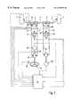
- FIG. 1is a schematic diagram of a first embodiment of the steering system in accordance with the present invention.
- FIG. 2is a similar diagram but of a second embodiment
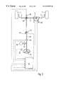
- FIG. 3is a similar view of yet another embodiment of the present invention.
- a motor vehiclehas steerable front wheels 1 which are steering-adjustably coupled with one another by way of tie rods 2 and a rod 3 .
- the rod 3forms the piston rod of two piston-cylinder units 4 , 5 which are arranged parallel to one another and which are each constructed as double-acting units forming a steering adjusting drive.
- the piston-cylinder unit 4is coupled by two hydraulic lines 6 , 7 with the two piston working spaces of a double-acting piston-cylinder unit 8 , whose pistons are mechanically forcibly coupled with a manual steering wheel 9 .
- the pistons of the unit 8are displaced to the right or the left when the manual steering wheel is turned clockwise or counterclockwise. During the displacement of the pistons of the piston-cylinder unit 8 , the manual steering wheel is rotated correspondingly.
- the manual steering wheel 9is connected with respect to the drive with an electric motor 10 which is irreversible and which, when the engine shaft is stopped, is capable of operating as a pure power generator for a purpose will be explained below.
- a normally-closed shut-off valve 11is arranged which, by energization of its operating magnet, can be switched over against the force of a restoring spring, from the illustrated closed position into its open position.
- the valve 11is automatically brought by the restoring spring into and held in the illustrated closed position.
- the piston-cylinder unit 5is connected with two connections of a control valve 14 .
- the latteris connected by way of two additional connections with a relatively pressureless hydraulic reservoir 15 and a hydraulic pressure source, for example, a hydraulic pressure accumulator 16 and pumps 17 , 18 .
- the pressure accumulator 16can be recharged by the pump 17 as well as the other pump 18 .
- Both pumps 17 , 18are secured by return valves 19 against a return from the delivery side to their suction side and, on the suction side, are connected to the reservoir 15 .
- the pump 17is driven by an electric motor 20 .
- the pump 18can be connected with the schematically-shown engine 22 of the motor vehicle.
- a normally open shut-off valve 23is arranged which can be changed, by the electric energization of its operating magnet, against the force of a restoring spring from the illustrated open position into its closed position where it is held.
- An electronic automatic control and control system 24is connected on the input side with a generator 25 for the actual value of the steering angle of the front wheels 1 .
- This generator 25can interact, for example, with the rod 3 which, during the steering adjustment of the wheels 1 , carries out an adjusting stroke analogous to the steering angle.
- the input side of the automatic control and control system 24is connected with a generator for the desired value of the steering angle operated by the manual steering wheel 9 .
- the input side of the automatic control and control systemis connected with a torque sensor 27 which senses the forces and torques effective between the manual steering wheel 9 and the piston-cylinder unit 8 .
- the torque generated by the electric motor 10can be determined by another sensor or, at least approximately, by the detection of the electric current flowing through the electric motor.
- a large or sufficient number of pressure sensors 28 , 29 and 30are connected to the input side of the automatic control and control system.
- the signals of these sensorsreflect the hydraulic pressure in the hydraulic lines 6 and 7 , 12 and 13 , as well as the pressure at the pressure input of the control valve 14 .
- the automatic control and control system 24is connected with the operating magnets of the shut-off valves 11 and 23 as well as of the control valve 14 .
- the electric motors 10 , 20 and the clutch 21are controlled by the output of the automatic control and control system.
- the switch-over valves 11 , 23are changed into unillustrated positions and held there by the automatic control and control system 24 by energizing the associated operating magnets.
- the piston-cylinder unit 4is correspondingly hydraulically uncoupled from the piston-cylinder unit 8 as well as from the manual steering wheel 9 .
- the pressure difference between the two piston working spaces of the piston-cylinder unit 5is controlled by the operation of the control valve 14 .
- the automatic control and control system 24detects the actual value of the steering angle of the front wheels 1 by way of the generator 25 .
- the automatic control and control system 24receives the desired value of the steering angle via the generator 26 operated by the manual steering wheel.
- the operating magnets of the control valve 14are then controlled.
- the control valve 14remains in the illustrated center position. In that position, the piston-cylinder unit 5 is hydraulically switched to free-running and is connected with the reservoir 15 , while the pressure accumulator 16 which, as a function of the signal of the pressure sensor 30 , is constantly recharged as required by way of the pumps 17 , 18 , is shut-off with respect to the piston-cylinder unit 5 . If a desired-actual value deviation occurs, the control valve 14 is displaced from the illustrated center position, according to the direction of the desired actual value deviation, toward the right or the left.
- a piston working space of the piston-cylinder unit 5is controllably connected with the pressure connection of the control valve 14 , and the other piston working space of the unit 5 is controllably connected with the reservoir 15 .
- a controllable pressure differencebecomes effective at the piston-cylinder unit 5 with the result that the piston-cylinder unit 5 generates an adjusting force in a direction defined by the direction of the desired- actual value deviation of the steering angle. In this manner, a desired-actual value deviation of the steering angle is controlled within a short time and the front wheels 1 follow the steering adjustment of the manual steering wheel 9 .
- the automatic control and control system 24can directly or indirectly determine the pressure difference effective at the piston-cylinder unit 5 .
- the extent of this pressure differenceis correlated with the forces and torques transmitted between the steered wheels 1 and the piston-cylinder unit 5 .
- the automatic control and control system 24determines a desired value for a manual force which can be felt at the manual steering wheel 9 , and this desired value is set by a corresponding control of the electric motor 10 .
- the torque sensor 27senses the forces and torques effective between the electric motor 10 and the manual steering wheel 9 and thus detects the actual value of the manual force.
- the motor 10is thus controlled as a function of a desired-actual value comparison for the manual forces.
- the driverobtains at the manual steering wheel 9 a haptic feedback of the forces effective between the steered vehicle wheels 1 and the piston-cylinder unit 5 .
- the automatic control and control system 24continuously monitors itself with respect to a correct operation. Furthermore, the signals of the generators and sensors 25 to 30 connected with the input side of the automatic control and control system 24 are continuously checked with respect to their plausibility. Should a system error be determined, the operating magnet of the shut-off valve 11 is switched to a current-free state. As a result, the shut-off valve 11 switches over into the closed position illustrated in FIG. 1, and the piston-cylinder units 4 , 8 (and thus the steerable front wheels 1 and the manual steering wheel 9 ) are forcedly hydraulically coupled with one another.
- the operating magnet of the shut-off valve 23is also switched to a current-free state, so that this valve 23 takes up the open position illustrated in FIG. 1 and the piston-cylinder unit 5 is switched to free-running under all circumstances.
- the hydraulic system of the piston-cylinder unit 5including the control valve 14 , is deemed to be operative, the piston-cylinder unit 5 can be controlled, similar to a conventional power steering system, for reducing the forces transmitted between the manual steering wheel 9 and the steered vehicle wheels 1 .
- the pressure difference detected by the pressure sensors 28 between the lines 6 , 7 according to the direction and amountis an analogous measurement with respect to the forces and torques transmitted between the manual steering wheel 9 and the steered vehicle wheels 1 .
- the automatic control and control system 24now controls the operating magnets of the control valve 14 so that the above-mentioned pressure difference is reduced.
- the illustrated steering systemoperates like a conventional power steering system.
- a situationmay occur during the normal operation, i.e., when the control valve 14 is controlled as a function of the desired-actual value difference of the steering angles which is detected by the actual and desired value generators that the piston cylinder unit 5 , which is used as a steering adjusting drive for the wheels 1 , reaches its constructively provided performance limit.
- This operating conditioncan be determined, on one hand, by analyzing the signals of the pressure sensors 29 because, in such an operating phase, pressure differences must occur between the lines 12 , 13 which come close to the pressure at the pressure sensor 30 .
- the electric voltages and current intensities at the operating magnets of the control valve 14are also an indicator of the above-mentioned operating condition. The reason is that the extreme position of the control valve 14 , which is characteristic of this operating condition, is reached only if energization of the operating magnets differs considerably.
- the switch-over valve 11is switched into the illustrated closed position to establish a hydraulic forced coupling between the manual steering wheel 9 and the steered vehicle wheels 1 . This then permits the generation of an additional force by the manual steering wheel 9 which assists the adjusting force of the piston-cylinder unit. Steering forces can be generated in this manner which exceed the performance capability of the piston-cylinder unit 5 .
- the automatic control and control system 24controls the electric motor 10 preferably in a manner opposite to that in the normal operation. That is, during normal operation, the electric motor 10 simulates a steering resistance which is analogous to the adjusting force of the piston-cylinder unit 5 , and thus operates against the manual force of the driver. In an operating condition with a high steering force requirement, the electric motor 10 preferably operates in a manner which assists the piston-cylinder unit. The electric motor 10 thus generates a torque which assists the driver at the manual steering wheel 9 and which is correlated with the signals generated by the sensor 27 . As in the normal operation, the steering torque generated by the servo motor 10 in an operating mode with a high steering force requirement is detected by the sensor 27 or by way of the polarity and intensity of the electric motor current.
- the total steering forces effective at the steerable wheels 1can be determined by the automatic control and control unit 24 from the signals of the pressure sensors 28 , 29 .
- the signals of the latter pressure sensor 29optionally can also be replaced or checked for their plausibility by the detection of the energization of the operating magnets of the control valve 14 as well as of the signals of the pressure sensor 30 .
- the signals of the pressure sensors 28can optionally be replaced or checked with respect to their plausibility such that, when the switch-over valve 11 is switched into the illustrated closed position, i.e., when the hydraulic forced coupling is established between the piston-cylinder units 4 , 8 , the automatic control and control system 24 stores the relation of the actual-value signal of the steering angle with respect to the desired value signal of the steering angle generated by the generator 26 . Taking into account the hydraulic ratio between the hydraulic units 4 , 8 , the automatic control and control system 24 then “knows” which signals of the generators 25 , 26 must coincide when no forces and torques (or at most vanishing forces and torques) are hydraulically transmitted between the piston-cylinder units 4 , 8 .
- the automatic control or control system 24knows the sum of the steering adjusting forces which are generated in parallel by the piston-cylinder units 4 , 5 . As long as this sum is above or in the proximity of the forces which can be maximally generated by the piston-cylinder unit 5 alone, the forced coupling between the units 4 , 8 (and thus the forced coupling between the manual steering wheel 9 and the steerable vehicle wheels 1 ) is maintained. As soon as the above-mentioned sum of forces falls below a threshold value, the switch-over valve 11 is opened up again by the automatic control and control system. The control of the control valve 14 will then again take place corresponding to the normal operation as a function of the desired-actual value difference of the steering angle determined by the generators 25 , 26 .
- the force of the piston-cylinder unit 5is adjusted such that, by the corresponding controlling of the control valve 14 by the automatic control and control system 24 , the forces transmitted between the piston-cylinder units 4 , 8 only still have a small residual value.
- the direction of this residual forceis aligned such that the piston-cylinder unit 4 generates a residual adjusting force in the same direction as the adjusting force of the unit 5 .
- the electric motor 10advantageously always, as in the normal operation, generates a steering resistance which is correlated with the adjusting forces generated by the piston cylinder unit 5 .
- the steering resistance generated by the electric motor 10can decrease progressively when the forces which are hydraulically transmitted between the piston-cylinder units 4 , 8 and which can be determined from the signals of the pressure sensors 28 or of the generators 25 , 26 , rise in comparison to the adjusting forces generated by the piston-cylinder unit 5 , which can be determined from the signals of the pressure sensors 29 or the energization of the operating magnets of the control valve.
- the steering resistance generated by the electric motor 10can therefore depend on the ratio of the forces generated by the piston-cylinder units 4 , 5 . As soon as the forces transmitted between the units 4 , 5 fall or approach a vanishing value, the electric motor 10 is, however, again controlled normally in a normal correlation with the adjusting forces generated by the unit 5 .
- FIG. 2differs from the arrangement according to FIG. 1 essentially in that the piston-cylinder unit 8 is replaced by a hydrostatic reversible pump 31 .
- this pump 31is, on one hand, forcedly coupled with the electric motor 10 and, on the other hand, with the manual steering wheel 9 .
- another reversible and preferably also hydrostatic pump 32can connect the hydraulic lines 12 , 13 .
- an electric motor 33is used which is operated by the automatic control and control system 24 .
- the method of operation of the embodiment of FIG. 2largely corresponds to the method of operation of the embodiment of FIG. 1 .
- the switch-over valve 11takes up its closed position, the hydrostatic pump 31 and the piston-cylinder unit 4 and thus the steerable vehicle wheels 1 and the manual steering wheel 9 are forcedly coupled with one another.
- the switch-over valves 11 , 23are held by the automatic control and control system 23 in each case in their positions not illustrated in FIG. 2 .
- the electric motor 33is then operated by the automatic control or control system 24 as a function of a desired-actual value comparison of the steering angle, that is, as a function of the difference between the signals of the generators 25 , 26 , in one or the other direction with a more or less high adjusting force so -that the piston-cylinder unit 5 transmits a corresponding adjusting force to the steered wheels 1 .
- the embodiment illustrated in FIG. 3differs from the above-described embodiments first in that, for an emergency, a mechanical through-drive is provided between the manual steering wheel 9 and the steered vehicle wheels 1 .
- the rod 3 in the illustrated embodimentis arranged as a toothed rack which meshes with a pinion 40 which, in turn, is mechanically connected with the manual steering wheel 9 by way of a clutch, which is acted upon in the closing direction by a spring, and an adjoining shaft 42 .
- the clutch 41can be opened by a servo motor against the force of its closing spring in order to open up a mechanical through-drive between the steered vehicle wheels and the manual steering wheel 9 .
- this shaft 42is also connected with a reversable electric motor 10 (non-irreversibly).
- Torque sensors 44 , 45are in each case arranged between the manual steering wheel 9 and the shaft 42 as well as between the electric motor 10 and the shaft 42 .
- the pinion 40is connected with the generator 25 for determining the actual value of the steering angle which is constructed as an angle sensor.
- the shaft 42is connected on the manual steering wheel 9 with the generator 26 which is also constructed as an angle sensor and which is used as a generator for the desired value of the steering angle in normal operation.
- the rod 3again forms the piston rod of the piston-cylinder unit 5 which can be operated again according to the arrangement of FIG. 1 or 2 .
- the servo motor 43 of the clutch 41is continuously energized by the automatic control and control system 24 such that it holds open the clutch 41 against the force of its closing spring. Furthermore, the automatic control and control system 24 operates the piston-cylinder unit 5 or the elements controlling this unit 5 . Thereby, as the result of the adjusting forces generated by the unit, a possible difference is controlled between the desired value of the steering angle supplied by the generator 26 and the actual value of the steering angle supplied by the generator 25 . For this purpose, reference is made to the descriptions of FIGS. 1 and 2.
- the servo motor 43is switched off by the automatic control and control system 24 , so that the clutch 41 closes and the manual steering wheel and the steered vehicle wheels 1 are forcedly coupled with one another. If a disturbance is present in the hydraulic system of the piston-cylinder unit 5 or appears possible, the piston-cylinder unit 5 is simultaneously switched to hydraulic free running, as explained above with respect to FIGS. 1 and 2.
- the automatic control and control system 24can determine the sum of the effective steering forces from the signals generated by the pressure generators 29 , which signals reflect the adjusting force of the piston-cylinder unit 5 , as well as from the signals generated by the torque sensors, which signals indicate the steering forces additionally transmitted by way of the clutch 41 to the wheels 1 .
- the signals 45 of the sensor 45can optionally be supplemented or replaced by the detection of the polarity and intensity of the electric current flowing through the motor 10 .
- the steering forces generated by the mechanical through-drivecan optionally also be determined from the signals of the generators 25 , 26 as well as from the polarity and intensity of the electric current flowing through the electric motor 10 , provided that the automatic control and control system 24 has recorded the relation of the signals of the generators 25 , 26 during the closing of the clutch and thus “knows” at which signal relation a condition of the shaft 42 exists between the generators 25 , 26 which is free of torsional tension.
- the shaft 42is torqued more or less, the extent of the torsion and thus the extent of the torques transmitted by the shaft 42 being determinable from the signals of the generators 25 , 26 .
- the torque sensor 45permits the steering resistance generated by the electric motor 10 to be determined in all operating conditions. As a result, the same operating mode can therefore be achieved as in the embodiment of FIG. 1 .
- the transmission ratio between the rotating angle of the manual steering wheel 9 and the steering angle of the steered vehicle wheels 1 in the steer-by-wire modewill have a different value than in operating conditions with a mechanical or hydraulic forced coupling between the manual steering wheel 9 and the steered vehicle wheels 1 .
- Thisis taken into account by the automatic control and control system 24 particularly if a switching-back from an operating phase, in which the steering adjusting drive or the piston-cylinder unit 5 operates in parallel with the assisting operation of the switched-on forced coupling between the manual steering wheel 9 and the steered vehicle wheels 1 , takes place into the steer-by-wire mode.
- the automatic control and control system 24will then, during the newly switched-on steer-by-wire mode, change the transmission ratio between the rotating movements of the manual steering wheel and the steering angle change of the steered vehicle wheels such that the manual steering wheel 9 reaches its position assigned to the straight-ahead position of the steered vehicle wheels 1 when the steered vehicle wheels 1 arrive in their straight-ahead position. Subsequently, the transmission ratio can then be used which is normally provided for the steer-by-wire mode.
- the senor 27can also be arranged on the manual steering wheel side of the unit 8 or of the pump 31 .
- the sensor 44can also be arranged on the manual steering wheel side of the driving connection between the electric motor 10 and the shaft 42 .
Landscapes
- Engineering & Computer Science (AREA)
- Chemical & Material Sciences (AREA)
- Combustion & Propulsion (AREA)
- Transportation (AREA)
- Mechanical Engineering (AREA)
- Steering Control In Accordance With Driving Conditions (AREA)
- Power Steering Mechanism (AREA)
Abstract
Description
Claims (8)
Applications Claiming Priority (2)
| Application Number | Priority Date | Filing Date | Title |
|---|---|---|---|
| DE19839953 | 1998-09-02 | ||
| DE19839953ADE19839953C2 (en) | 1998-09-02 | 1998-09-02 | Steering system for non-track-bound motor vehicles |
Publications (1)
| Publication Number | Publication Date |
|---|---|
| US6279675B1true US6279675B1 (en) | 2001-08-28 |
Family
ID=7879536
Family Applications (1)
| Application Number | Title | Priority Date | Filing Date |
|---|---|---|---|
| US09/388,550Expired - LifetimeUS6279675B1 (en) | 1998-09-02 | 1999-09-02 | Steering system for non-tracked motor vehicles |
Country Status (4)
| Country | Link |
|---|---|
| US (1) | US6279675B1 (en) |
| EP (1) | EP0983926B1 (en) |
| JP (1) | JP3374349B2 (en) |
| DE (2) | DE19839953C2 (en) |
Cited By (37)
| Publication number | Priority date | Publication date | Assignee | Title |
|---|---|---|---|---|
| US6382342B1 (en)* | 2000-06-20 | 2002-05-07 | Trw Inc. | Hydraulically powered steering apparatus with electrically powered backup |
| US6484839B2 (en)* | 2000-12-01 | 2002-11-26 | Delphi Technologies, Inc. | Steer-by-wire rotary actuator |
| US6488112B1 (en)* | 1999-11-16 | 2002-12-03 | Trw Fahrwerksysteme Gmbh & Co. Kg | Electrohydraulic steering system |
| US6548969B2 (en)* | 2000-12-29 | 2003-04-15 | Delphi Technologies, Inc. | Redundant steer-by-wire system |
| US6588540B2 (en)* | 2001-07-26 | 2003-07-08 | Delphi Technologies, Inc. | Steer-by-wire redundant handwheel control |
| US6609052B2 (en)* | 2001-03-16 | 2003-08-19 | Visteon Global Technologies, Inc. | Torque sensor backup in a steer-by-wire system |
| US6612395B2 (en)* | 2000-05-05 | 2003-09-02 | Daimlerchrysler Ag | Steering system for a vehicle |
| US6612393B2 (en)* | 2001-01-17 | 2003-09-02 | Daimlerchrysler Ag | Steering system for motor vehicles |
| US6625530B1 (en) | 2000-11-06 | 2003-09-23 | Delphi Technologies, Inc. | Feed forward—feed back control for steer-by-wire system |
| US6678594B2 (en) | 2001-02-02 | 2004-01-13 | Delphi Technologies, Inc. | User-configurable steering control for steer-by-wire systems |
| US6678597B2 (en) | 2001-09-14 | 2004-01-13 | Delphi Technologies, Inc. | Complementary force and position control for an automotive steering system |
| FR2842490A1 (en)* | 2002-07-18 | 2004-01-23 | Renault Vehicules Ind | VEHICLE STEERING SYSTEM |
| US20040026158A1 (en)* | 2000-03-27 | 2004-02-12 | Peter Rieth | Vehicle system and axle guide module for a vehicle steering system |
| US20040031429A1 (en)* | 2002-02-13 | 2004-02-19 | Kaufmann Timothy W. | Watercraft steer-by-wire system |
| US20040089498A1 (en)* | 2000-07-01 | 2004-05-13 | Johannes Kaltenbach | Steering system |
| US6786296B2 (en)* | 2002-05-30 | 2004-09-07 | Bayerische Motoren Werke Aktiengesellschaft | Back-drivable steer-by-wire system with positive scrub radius |
| US6817437B2 (en) | 2001-06-19 | 2004-11-16 | Delphi Technologies, Inc. | Steer-by wire handwheel actuator |
| US20040238258A1 (en)* | 2003-05-29 | 2004-12-02 | Nissan Motor Co., Ltd. | Steering apparatus and method for automotive vehicle |
| US20050056480A1 (en)* | 2003-09-16 | 2005-03-17 | Hitachi Unisia Automotive, Ltd. | Power steering system |
| US20050150710A1 (en)* | 2001-05-17 | 2005-07-14 | Hitachi, Ltd. | Power steering device |
| US7100733B2 (en) | 2002-07-22 | 2006-09-05 | Visteon Global Technologies, Inc. | Method to initialize steering wheel in a steer-by-wire system |
| US20070215405A1 (en)* | 2006-03-03 | 2007-09-20 | Nissan Motor Co., Ltd. | Vehicle steering control apparatus and method |
| CN100358764C (en)* | 2004-06-22 | 2008-01-02 | 现代摩比斯 | Fail-safe steering apparatus for steer-by-wire system |
| US20080006469A1 (en)* | 2003-08-19 | 2008-01-10 | Hitachi,Ltd. | Power Steering Device and Method of Controlling the Power Steering Device |
| US20080230301A1 (en)* | 2004-04-27 | 2008-09-25 | Daimerchrysler Ag | Steering System for Motor Vehicles |
| US20080257634A1 (en)* | 2004-02-18 | 2008-10-23 | Walter Kogel | Hydraulic Power Steering System |
| US20090118904A1 (en)* | 2006-02-27 | 2009-05-07 | Denis Allan Birnie | Method and system for planning the path of an agricultural vehicle |
| US20100006366A1 (en)* | 2006-10-23 | 2010-01-14 | Renault Trucks | Steering system for controlling the turning angle of the steering wheels of a vehicle |
| WO2010033456A3 (en)* | 2008-09-18 | 2010-06-10 | Trw Automotive U.S. Llc | Method of controlling a vehicle steering apparatus |
| US20100147618A1 (en)* | 2008-12-16 | 2010-06-17 | Nissan Motor Co., Ltd. | Steering control apparatus |
| US20110094820A1 (en)* | 2008-05-02 | 2011-04-28 | Bayerische Motoren Werke Aktiengesellschaft | Vehicle Steering System of the By-Wire Design Type |
| US20120160594A1 (en)* | 2010-12-24 | 2012-06-28 | Unisia JKC Streering Systems Co, Ltd. | Power Steering System |
| US20130037341A1 (en)* | 2011-08-09 | 2013-02-14 | Jtekt Corporation | Hydraulic power steering system |
| GB2516447A (en)* | 2013-07-22 | 2015-01-28 | Jc Bamford Excavators Ltd | A Steering Arrangement |
| US9266552B2 (en) | 2013-08-05 | 2016-02-23 | Rene Guerster | Steering system for wheeled land vehicle |
| US20180281852A1 (en)* | 2017-04-03 | 2018-10-04 | Deere & Company | Electro-hydraulic steering control system |
| US20190100240A1 (en)* | 2017-09-26 | 2019-04-04 | Weber-Hydraulik Gmbh | Hydraulic unit, method for operating a hydraulic unit, and steering system |
Families Citing this family (9)
| Publication number | Priority date | Publication date | Assignee | Title |
|---|---|---|---|---|
| DE19839951C2 (en)* | 1998-09-02 | 2000-06-21 | Daimler Chrysler Ag | Steering system for non-track-bound motor vehicles |
| FR2810615B1 (en)* | 2000-06-27 | 2002-10-11 | Renault Vehicules Ind | MOTOR VEHICLE POWER STEERING DEVICE |
| DE10122153A1 (en)* | 2001-05-08 | 2002-11-14 | Bayerische Motoren Werke Ag | Steering system for a motor vehicle |
| DE10159297A1 (en)* | 2001-12-04 | 2003-06-12 | Mercedes Benz Lenkungen Gmbh | Two-circuit steer-by-wire steering system with two hydraulically operated actuators |
| DE10217716A1 (en)* | 2002-04-20 | 2003-11-06 | Zf Lenksysteme Gmbh | Power or servo steering system automatically sets steerable wheel angle to straight ahead without operator applying control movement to steering control before departure and/or after journey |
| DE10245973B4 (en)* | 2002-09-30 | 2007-11-15 | Deutsche Bahn Regio Ag | Bus coupling |
| DE10351618B4 (en)* | 2003-11-05 | 2011-06-09 | Man Nutzfahrzeuge Ag | Commercial vehicle steering |
| DE102004048495A1 (en)* | 2003-11-14 | 2005-11-17 | Continental Teves Ag & Co. Ohg | Method for improving the operation of a vehicle steering and vehicle steering |
| CN103419836B (en)* | 2012-05-14 | 2016-06-08 | 北汽福田汽车股份有限公司 | The control method of vehicle steering device and this vehicle steering device |
Citations (9)
| Publication number | Priority date | Publication date | Assignee | Title |
|---|---|---|---|---|
| US5097917A (en)* | 1987-12-26 | 1992-03-24 | Honda Giken Kogyo Kabushiki Kaisha | Steering system of vehicle |
| US5862878A (en)* | 1995-12-14 | 1999-01-26 | Mercedes-Benz Ag | Hydraulic power steering system |
| US5893427A (en)* | 1996-01-30 | 1999-04-13 | Mercedes-Benz Ag | Hydraulic power steering for motor vehicles |
| US6047788A (en)* | 1995-07-11 | 2000-04-11 | Daimlerchrysler A.G. | Hydraulic power steering system with dual, double-acting piston-cylinder units |
| US6059068A (en)* | 1997-01-21 | 2000-05-09 | Koyo Seiko Co., Ltd. | Steering apparatus for a vehicle |
| US6076626A (en)* | 1996-02-15 | 2000-06-20 | Daimlerchrysler Ag | Steering system for multi-track motor vehicles |
| US6076627A (en)* | 1995-11-03 | 2000-06-20 | Daimlerchrysler Ag | Power steering for motor vehicles |
| US6102150A (en)* | 1996-04-19 | 2000-08-15 | Daimlerchrysler Ag | Vehicle steering mechanism |
| US6138788A (en)* | 1997-12-11 | 2000-10-31 | Daimlerchrysler Ag | Vehicle steering system |
Family Cites Families (3)
| Publication number | Priority date | Publication date | Assignee | Title |
|---|---|---|---|---|
| DE4304664C2 (en)* | 1993-02-16 | 2000-04-06 | Daimler Chrysler Ag | Control device, in particular steering for motor vehicles |
| DE4422386C1 (en)* | 1994-06-27 | 1995-09-28 | Daimler Benz Ag | Parameter-dependent resistance force control for hydraulic servo steering |
| DE19546942C1 (en) | 1995-12-15 | 1997-06-19 | Daimler Benz Ag | Hydraulic power steering |
- 1998
- 1998-09-02DEDE19839953Apatent/DE19839953C2/ennot_activeExpired - Fee Related
- 1999
- 1999-08-10EPEP99115743Apatent/EP0983926B1/ennot_activeExpired - Lifetime
- 1999-08-10DEDE59907606Tpatent/DE59907606D1/ennot_activeExpired - Lifetime
- 1999-09-01JPJP28582399Apatent/JP3374349B2/ennot_activeExpired - Fee Related
- 1999-09-02USUS09/388,550patent/US6279675B1/ennot_activeExpired - Lifetime
Patent Citations (9)
| Publication number | Priority date | Publication date | Assignee | Title |
|---|---|---|---|---|
| US5097917A (en)* | 1987-12-26 | 1992-03-24 | Honda Giken Kogyo Kabushiki Kaisha | Steering system of vehicle |
| US6047788A (en)* | 1995-07-11 | 2000-04-11 | Daimlerchrysler A.G. | Hydraulic power steering system with dual, double-acting piston-cylinder units |
| US6076627A (en)* | 1995-11-03 | 2000-06-20 | Daimlerchrysler Ag | Power steering for motor vehicles |
| US5862878A (en)* | 1995-12-14 | 1999-01-26 | Mercedes-Benz Ag | Hydraulic power steering system |
| US5893427A (en)* | 1996-01-30 | 1999-04-13 | Mercedes-Benz Ag | Hydraulic power steering for motor vehicles |
| US6076626A (en)* | 1996-02-15 | 2000-06-20 | Daimlerchrysler Ag | Steering system for multi-track motor vehicles |
| US6102150A (en)* | 1996-04-19 | 2000-08-15 | Daimlerchrysler Ag | Vehicle steering mechanism |
| US6059068A (en)* | 1997-01-21 | 2000-05-09 | Koyo Seiko Co., Ltd. | Steering apparatus for a vehicle |
| US6138788A (en)* | 1997-12-11 | 2000-10-31 | Daimlerchrysler Ag | Vehicle steering system |
Cited By (61)
| Publication number | Priority date | Publication date | Assignee | Title |
|---|---|---|---|---|
| US6488112B1 (en)* | 1999-11-16 | 2002-12-03 | Trw Fahrwerksysteme Gmbh & Co. Kg | Electrohydraulic steering system |
| US20040026158A1 (en)* | 2000-03-27 | 2004-02-12 | Peter Rieth | Vehicle system and axle guide module for a vehicle steering system |
| US6612395B2 (en)* | 2000-05-05 | 2003-09-02 | Daimlerchrysler Ag | Steering system for a vehicle |
| US6382342B1 (en)* | 2000-06-20 | 2002-05-07 | Trw Inc. | Hydraulically powered steering apparatus with electrically powered backup |
| US6892848B2 (en) | 2000-07-01 | 2005-05-17 | Zf Friedrichshafen Ag | Steering system |
| US20040089498A1 (en)* | 2000-07-01 | 2004-05-13 | Johannes Kaltenbach | Steering system |
| US6625530B1 (en) | 2000-11-06 | 2003-09-23 | Delphi Technologies, Inc. | Feed forward—feed back control for steer-by-wire system |
| US6484839B2 (en)* | 2000-12-01 | 2002-11-26 | Delphi Technologies, Inc. | Steer-by-wire rotary actuator |
| US6548969B2 (en)* | 2000-12-29 | 2003-04-15 | Delphi Technologies, Inc. | Redundant steer-by-wire system |
| US6612393B2 (en)* | 2001-01-17 | 2003-09-02 | Daimlerchrysler Ag | Steering system for motor vehicles |
| US6678594B2 (en) | 2001-02-02 | 2004-01-13 | Delphi Technologies, Inc. | User-configurable steering control for steer-by-wire systems |
| US6609052B2 (en)* | 2001-03-16 | 2003-08-19 | Visteon Global Technologies, Inc. | Torque sensor backup in a steer-by-wire system |
| US20050150710A1 (en)* | 2001-05-17 | 2005-07-14 | Hitachi, Ltd. | Power steering device |
| US7325645B2 (en)* | 2001-05-17 | 2008-02-05 | Hitachi, Ltd. | Power steering device |
| US6817437B2 (en) | 2001-06-19 | 2004-11-16 | Delphi Technologies, Inc. | Steer-by wire handwheel actuator |
| US6588540B2 (en)* | 2001-07-26 | 2003-07-08 | Delphi Technologies, Inc. | Steer-by-wire redundant handwheel control |
| US6687588B2 (en) | 2001-09-14 | 2004-02-03 | Delphi Technologies, Inc. | Compensation using position for improved feel and stability in a steering system |
| US6678597B2 (en) | 2001-09-14 | 2004-01-13 | Delphi Technologies, Inc. | Complementary force and position control for an automotive steering system |
| US7036445B2 (en) | 2002-02-13 | 2006-05-02 | Delphi Technologies, Inc. | Watercraft steer-by-wire system |
| US20040031429A1 (en)* | 2002-02-13 | 2004-02-19 | Kaufmann Timothy W. | Watercraft steer-by-wire system |
| US20060124043A1 (en)* | 2002-02-13 | 2006-06-15 | Tracht Steven L | Watercraft steer-by-wireless system |
| US7404369B2 (en) | 2002-02-13 | 2008-07-29 | Delphi Technologies, Inc. | Watercraft steer-by-wireless system |
| US6786296B2 (en)* | 2002-05-30 | 2004-09-07 | Bayerische Motoren Werke Aktiengesellschaft | Back-drivable steer-by-wire system with positive scrub radius |
| WO2004009425A3 (en)* | 2002-07-18 | 2005-07-21 | Renault Vehicules Ind | Vehicle steering system |
| FR2842490A1 (en)* | 2002-07-18 | 2004-01-23 | Renault Vehicules Ind | VEHICLE STEERING SYSTEM |
| US7100733B2 (en) | 2002-07-22 | 2006-09-05 | Visteon Global Technologies, Inc. | Method to initialize steering wheel in a steer-by-wire system |
| US6938721B2 (en) | 2003-05-29 | 2005-09-06 | Nissan Motor Co., Ltd. | Steering apparatus and method for automotive vehicle |
| US20040238258A1 (en)* | 2003-05-29 | 2004-12-02 | Nissan Motor Co., Ltd. | Steering apparatus and method for automotive vehicle |
| US20080006469A1 (en)* | 2003-08-19 | 2008-01-10 | Hitachi,Ltd. | Power Steering Device and Method of Controlling the Power Steering Device |
| US7210554B2 (en)* | 2003-09-16 | 2007-05-01 | Hitachi Ltd. | Power steering system |
| US20050056480A1 (en)* | 2003-09-16 | 2005-03-17 | Hitachi Unisia Automotive, Ltd. | Power steering system |
| US7942230B2 (en)* | 2004-02-18 | 2011-05-17 | Zf Lenksysteme Gmbh | Hydraulic power steering system |
| US20080257634A1 (en)* | 2004-02-18 | 2008-10-23 | Walter Kogel | Hydraulic Power Steering System |
| US20080230301A1 (en)* | 2004-04-27 | 2008-09-25 | Daimerchrysler Ag | Steering System for Motor Vehicles |
| CN100358764C (en)* | 2004-06-22 | 2008-01-02 | 现代摩比斯 | Fail-safe steering apparatus for steer-by-wire system |
| US10378896B2 (en)* | 2006-02-27 | 2019-08-13 | Trimble Inc. | Method and system for planning the path of an agricultural vehicle |
| US20090118904A1 (en)* | 2006-02-27 | 2009-05-07 | Denis Allan Birnie | Method and system for planning the path of an agricultural vehicle |
| US7690475B2 (en)* | 2006-03-03 | 2010-04-06 | Nissan Motor Co., Ltd. | Vehicle steering control apparatus and method |
| CN101028832B (en)* | 2006-03-03 | 2010-06-02 | 日产自动车株式会社 | Vehicle steering controlling device and method |
| US20070215405A1 (en)* | 2006-03-03 | 2007-09-20 | Nissan Motor Co., Ltd. | Vehicle steering control apparatus and method |
| US7980353B2 (en)* | 2006-10-23 | 2011-07-19 | Renault Trucks | Steering system for controlling the turning angle of the steering wheels of a vehicle |
| US20100006366A1 (en)* | 2006-10-23 | 2010-01-14 | Renault Trucks | Steering system for controlling the turning angle of the steering wheels of a vehicle |
| US20110094820A1 (en)* | 2008-05-02 | 2011-04-28 | Bayerische Motoren Werke Aktiengesellschaft | Vehicle Steering System of the By-Wire Design Type |
| US8162095B2 (en)* | 2008-05-02 | 2012-04-24 | Bayerische Motoren Werke Aktiengesellschaft | Vehicle steering system of the by-wire design type |
| WO2010033456A3 (en)* | 2008-09-18 | 2010-06-10 | Trw Automotive U.S. Llc | Method of controlling a vehicle steering apparatus |
| US8483910B2 (en) | 2008-09-18 | 2013-07-09 | Trw Automotive U.S. Llc | Method of controlling a vehicle steering apparatus |
| US20100147618A1 (en)* | 2008-12-16 | 2010-06-17 | Nissan Motor Co., Ltd. | Steering control apparatus |
| US20120160594A1 (en)* | 2010-12-24 | 2012-06-28 | Unisia JKC Streering Systems Co, Ltd. | Power Steering System |
| US8479870B2 (en)* | 2010-12-24 | 2013-07-09 | Hitachi Automotive Systems Steering, Ltd. | Power steering system |
| US8783408B2 (en)* | 2011-08-09 | 2014-07-22 | Jtekt Corporation | Hydraulic power steering system |
| US20130037341A1 (en)* | 2011-08-09 | 2013-02-14 | Jtekt Corporation | Hydraulic power steering system |
| RU2658067C2 (en)* | 2013-07-22 | 2018-06-19 | ДжейСи Бэмфорд Экскавейторс Лимитед | Steering arrangement |
| GB2516447B (en)* | 2013-07-22 | 2016-06-15 | Jc Bamford Excavators Ltd | A Steering Arrangement |
| US9744986B2 (en) | 2013-07-22 | 2017-08-29 | J. C. Bamford Excavators Limited | Steering arrangement |
| GB2516447A (en)* | 2013-07-22 | 2015-01-28 | Jc Bamford Excavators Ltd | A Steering Arrangement |
| US9266552B2 (en) | 2013-08-05 | 2016-02-23 | Rene Guerster | Steering system for wheeled land vehicle |
| US20180281852A1 (en)* | 2017-04-03 | 2018-10-04 | Deere & Company | Electro-hydraulic steering control system |
| US10668947B2 (en)* | 2017-04-03 | 2020-06-02 | Deere & Company | Electro-hydraulic steering control system |
| US11396323B2 (en) | 2017-04-03 | 2022-07-26 | Deere & Company | Electro-hydraulic steering control system |
| US20190100240A1 (en)* | 2017-09-26 | 2019-04-04 | Weber-Hydraulik Gmbh | Hydraulic unit, method for operating a hydraulic unit, and steering system |
| US11142240B2 (en)* | 2017-09-26 | 2021-10-12 | Weber-Hydraulik Gmbh | Hydraulic unit, method for operating a hydraulic unit, and steering system |
Also Published As
| Publication number | Publication date |
|---|---|
| DE19839953C2 (en) | 2000-06-21 |
| EP0983926A2 (en) | 2000-03-08 |
| DE59907606D1 (en) | 2003-12-11 |
| DE19839953A1 (en) | 2000-03-16 |
| EP0983926B1 (en) | 2003-11-05 |
| JP2000085605A (en) | 2000-03-28 |
| JP3374349B2 (en) | 2003-02-04 |
| EP0983926A3 (en) | 2002-09-11 |
Similar Documents
| Publication | Publication Date | Title |
|---|---|---|
| US6279675B1 (en) | Steering system for non-tracked motor vehicles | |
| US6209677B1 (en) | Steering system for non-tracked motor vehicles | |
| US6244371B1 (en) | Steering system for non-track-bound motor vehicles | |
| US6213246B1 (en) | Electrically actuated vehicle steering system | |
| US6336519B1 (en) | Steering system for motor vehicles | |
| US5862878A (en) | Hydraulic power steering system | |
| CN109291991B (en) | Dual-motor drive-by-wire composite steering system and control method thereof | |
| US5953978A (en) | Hydraulic power steering system | |
| US6612393B2 (en) | Steering system for motor vehicles | |
| US6076627A (en) | Power steering for motor vehicles | |
| US6283243B1 (en) | Method for operating a vehicle steering system | |
| US6976555B2 (en) | Motor vehicle steering system | |
| US7648003B2 (en) | Power steering system | |
| CN109774786B (en) | A multi-mode power steering system based on steer-by-wire and control method thereof | |
| JP4485802B2 (en) | Hydraulic servo steering device | |
| GB2306928A (en) | Power steering for motor vehicles | |
| US5092419A (en) | All-wheel steering | |
| JP2001512075A (en) | Central closed hydraulic power steering system | |
| US20060027418A1 (en) | Power steering apparatus | |
| JPH0532274B2 (en) | ||
| US6945352B2 (en) | Force-based power steering system | |
| JPH07196049A (en) | Vehicle steering system | |
| JP2008505795A (en) | Method for calculating hydraulic power steering and steering torque | |
| JP3131676B2 (en) | Vehicle steering system | |
| US6948584B2 (en) | Steering device |
Legal Events
| Date | Code | Title | Description |
|---|---|---|---|
| AS | Assignment | Owner name:DAIMLERCHRYSLER AG, GERMANY Free format text:ASSIGNMENT OF ASSIGNORS INTEREST;ASSIGNORS:BOHNER, HUBERT;MOSER, MARTIN;SCHNECKENBURGER, REINHOLD;REEL/FRAME:010433/0860;SIGNING DATES FROM 19990920 TO 19990923 | |
| STCF | Information on status: patent grant | Free format text:PATENTED CASE | |
| FEPP | Fee payment procedure | Free format text:PAYOR NUMBER ASSIGNED (ORIGINAL EVENT CODE: ASPN); ENTITY STATUS OF PATENT OWNER: LARGE ENTITY | |
| FPAY | Fee payment | Year of fee payment:4 | |
| AS | Assignment | Owner name:DAIMLER AG, GERMANY Free format text:CHANGE OF NAME;ASSIGNOR:DAIMLERCHRYSLER AG;REEL/FRAME:021064/0428 Effective date:20071019 | |
| AS | Assignment | Owner name:DAIMLERCHRYSLER AG, GERMANY Free format text:CORRECTIVE ASSIGNMENT TO CORRECT THE IDENTIFYING INFORMATION IN THE ASSIGNMENT DOCUMENT PREVIOUSLY RECORDED ON REEL 010433 FRAME 0860. ASSIGNOR(S) HEREBY CONFIRMS THE ASSIGNMENT OF ASSIGNOR'S INTEREST.;ASSIGNORS:BOHNER, HUBERT;MOSER, MARTIN;SCHNECKENBURGER, REINHOLD;REEL/FRAME:021078/0899;SIGNING DATES FROM 19990920 TO 19990923 Owner name:DAIMLERCHRYSLER AG, GERMANY Free format text:CORRECTIVE ASSIGNMENT TO CORRECT THE IDENTIFYING INFORMATION IN THE ASSIGNMENT DOCUMENT PREVIOUSLY RECORDED ON REEL 010433 FRAME 0860;ASSIGNORS:BOHNER, HUBERT;MOSER, MARTIN;SCHNECKENBURGER, REINHOLD;REEL/FRAME:021078/0899;SIGNING DATES FROM 19990920 TO 19990923 | |
| FPAY | Fee payment | Year of fee payment:8 | |
| AS | Assignment | Owner name:RAMSLE TECHNOLOGY GROUP GMBH, LLC, DELAWARE Free format text:ASSIGNMENT OF ASSIGNORS INTEREST;ASSIGNOR:DAIMLER AG;REEL/FRAME:021719/0080 Effective date:20080727 | |
| FEPP | Fee payment procedure | Free format text:PAYOR NUMBER ASSIGNED (ORIGINAL EVENT CODE: ASPN); ENTITY STATUS OF PATENT OWNER: LARGE ENTITY Free format text:PAYER NUMBER DE-ASSIGNED (ORIGINAL EVENT CODE: RMPN); ENTITY STATUS OF PATENT OWNER: LARGE ENTITY | |
| FEPP | Fee payment procedure | Free format text:PAYOR NUMBER ASSIGNED (ORIGINAL EVENT CODE: ASPN); ENTITY STATUS OF PATENT OWNER: LARGE ENTITY Free format text:PAYER NUMBER DE-ASSIGNED (ORIGINAL EVENT CODE: RMPN); ENTITY STATUS OF PATENT OWNER: LARGE ENTITY | |
| FPAY | Fee payment | Year of fee payment:12 | |
| AS | Assignment | Owner name:OL SECURITY LIMITED LIABILITY COMPANY, DELAWARE Free format text:MERGER;ASSIGNOR:RAMSLE TECHNOLOGY GROUP GMBH, LLC;REEL/FRAME:037358/0685 Effective date:20150826 |