US6279412B1 - Corrosion resistant exoskeleton arm linkage assembly - Google Patents
Corrosion resistant exoskeleton arm linkage assemblyDownload PDFInfo
- Publication number
- US6279412B1 US6279412B1US09/314,654US31465499AUS6279412B1US 6279412 B1US6279412 B1US 6279412B1US 31465499 AUS31465499 AUS 31465499AUS 6279412 B1US6279412 B1US 6279412B1
- Authority
- US
- United States
- Prior art keywords
- link
- protective cover
- protective
- robot arm
- facing surfaces
- Prior art date
- Legal status (The legal status is an assumption and is not a legal conclusion. Google has not performed a legal analysis and makes no representation as to the accuracy of the status listed.)
- Expired - Fee Related
Links
Images


Classifications
- B—PERFORMING OPERATIONS; TRANSPORTING
- B25—HAND TOOLS; PORTABLE POWER-DRIVEN TOOLS; MANIPULATORS
- B25J—MANIPULATORS; CHAMBERS PROVIDED WITH MANIPULATION DEVICES
- B25J19/00—Accessories fitted to manipulators, e.g. for monitoring, for viewing; Safety devices combined with or specially adapted for use in connection with manipulators
- B25J19/0075—Means for protecting the manipulator from its environment or vice versa
- Y—GENERAL TAGGING OF NEW TECHNOLOGICAL DEVELOPMENTS; GENERAL TAGGING OF CROSS-SECTIONAL TECHNOLOGIES SPANNING OVER SEVERAL SECTIONS OF THE IPC; TECHNICAL SUBJECTS COVERED BY FORMER USPC CROSS-REFERENCE ART COLLECTIONS [XRACs] AND DIGESTS
- Y10—TECHNICAL SUBJECTS COVERED BY FORMER USPC
- Y10T—TECHNICAL SUBJECTS COVERED BY FORMER US CLASSIFICATION
- Y10T74/00—Machine element or mechanism
- Y10T74/20—Control lever and linkage systems
- Y10T74/20207—Multiple controlling elements for single controlled element
- Y10T74/20305—Robotic arm
Definitions
- the present inventionrelates generally to the protection of robot arms exposed to corrosive atmospheres and, more particularly, to a system for congruently encapsulating the links of a multi-link robot arm with thin plastic corrosion resistant covers.
- Some robots devices that handle semiconductor wafersare required work in atmospheric environments that contain highly corrosive fluids (gaseous or liquid). These robotic devices require protection from the corrosive agents to improve overall performance of the product. If corrosion occurs, the arm members can generate particles that can lead to failures on the wafers being handled.
- One solution to this problemis to use materials that resist corrosion (i.e. 300 series stainless steel or coatings).
- materials that resist corrosioni.e. 300 series stainless steel or coatings.
- some designershave fabricated the arm members out of electro-polished stainless steel to improve corrosion resistance or prevent corrosive from occurring.
- Other designershave sprayed coatings on the structural materials to help isolate the corrosive agents from interacting with the base structural material thereby minimizing corrosion.
- the issues associated with these two solutionsare cost of the material, the uniformity of the coatings and the ability of the material to resist permeation of the corrosive agents.
- a systemfor shielding a robot arm against being splashed with fluids and comprises a protective shell-like cover of thin-walled plastic material impervious to fluids which is removably attached to the robot arm.
- the protective coverhas a contoured shape congruently conforming to the configuration of the robot arm and includes an upper member overlying the upwardly facing surfaces of the robot arm and an integral continuous side member proximally overlying the sidewall of the robot arm and extending to a lower rim generally coplanar with the downwardly facing surfaces of the robot arm.
- the upper member of the protective covergenerally overlies the upwardly facing surface of the robot arm while the peripherally extending sidewall generally overlies the outer facing surface of the peripherally extending sidewall.
- a protective plate of thin-walled plastic material impervious to fluidsmay also be removably attached to the downwardly facing surfaces of the robot arm and includes a peripheral rim generally coextensive with the peripherally extending sidewall of the link and proximate the lower rim of the protective cover when both the protective cover and the protective plate are so attached.
- a primary feature, then, of the present inventionis the provision of a system for the protection of robot arms exposed to corrosive atmospheres.
- Another feature of the present inventionis the provision of such a system according to which the links of a multi-link robot arm are congruently encapsulated with thin plastic corrosion resistant covers.
- Still another feature of the present inventionis the provision of such a system using such thin plastic corrosion resistant covers which are disposable and easily replaced.
- Yet another feature of the present inventionis the provision of such a system which utilizes such thin plastic corrosion resistance covers which are inexpensive to manufacture, install, and replace.
- FIG. 1is a perspective view of robot apparatus embodying the present invention
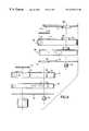
- FIG. 2is a side elevation view, exploded, of components illustrated in FIG. 1;
- FIG. 3is a perspective view, exploded, of the components illustrated in FIG. 2;
- FIG. 4is a side elevation view, partially cut away and in section, of the of components illustrated in FIGS. 2 and 3;
- FIG. 5is a detail side elevation view, in section and exploded, of some of the components illustrated in FIGS. 2, 3 , and 4 .
- FIG. 1there is shown a perspective view of robot apparatus 20 incorporating features of the present invention.
- the present inventionwill be described with reference to the single embodiment shown in the drawings, it should be understood that the present invention can be embodied in many alternate forms.
- any suitable size, shape or type of elements or materialscould be used.
- the robot apparatus 20incorporates a system for shielding each link of multi-link robot arm 22 against being splashed with fluids ranging from water to highly toxic substances to which the apparatus may be subjected when handling workpieces such as semiconductor wafers, introducing them to processing chambers, then subsequently retrieving them.
- the robot arm 22is comprised of three distinct assemblies which can be functionally compared to the arm structure of a human being.
- the robot armincludes an upper arm assembly 24 , a fore arm assembly 26 , and a hand-wrist assembly 28 .
- the assemblies 24 , 26 , and 28are generally similar, in order to completely describe the invention, each assembly will be discussed separately.
- the upper arm assembly 24includes an upper arm link 30 having upwardly facing surfaces 32 and downwardly facing surfaces 34 and a peripherally extending sidewall having outwardly facing surfaces 36 extending between the upwardly and downwardly facing surfaces.
- the various surface 32 , 34 , 36may be smooth and regular in some instances and may be highly contoured or irregular in other instances.
- the upper arm assembly 24further includes a shielding system according to the invention which comprises a protective shell-like cover 38 of thin-walled plastic material impervious to fluids and adapted to be removably attached to the upper arm link 30 .
- the protective cover 38has a contoured shape congruently conforming to the configuration of the upper arm link 30 and includes an upper member 40 overlying the upwardly facing surfaces 32 of the link and an integral continuous side member 42 proximally overlying the outwardly facing surfaces 36 of the sidewall of the upper arm link and extending to a lower rim 44 projecting beyond a plane of the downwardly facing surfaces 34 of the link.
- the upper member 40 of the protective cover 38generally overlies the upwardly facing surfaces 32 while the continuous side member 42 generally overlies the outwardly facing surfaces 36 of the peripherally extending sidewall.
- any splashing of the upper arm link 30issuing from an elevated location and directed toward the upper arm link is caused to impinge upon the protective cover thereby protecting the link.
- a protective plate 46 of thin-walled plastic material and impervious to fluidsmay also be provided for removable attachment to the downwardly facing surfaces 34 of the upper arm link 30 .
- the protective plate 46may be substantially planar and includes a peripheral rim 48 generally coextensive with the outwardly facing surfaces 36 of the peripherally extending sidewall of the upper arm link and proximate the lower rim 44 of the protective cover 38 when both the protective cover and the protective plate are attached thereto. With both the protective cover 38 and the protective plate 46 in place, any splashing of the upper arm link 30 issuing from any direction and directed toward the upper arm link is caused to impinge upon the protective cover and the protective plate thereby protecting the upper arm link. Together, the protective cover 38 and the protective plate 46 create a labyrinth seal at their overlapping regions which prevents the incursion of damaging fluids onto the surfaces of the upper arm link.
- the protective cover 38 and the protective plate 46are of any suitable low cost yet efficient plastic material having the necessary thickness to achieve the desired protection, yet not so think as to interfere with the operation of the robot arm 22 . To this end, these components may by of blow molded construction having a thickness in the range of about 30 to 40 mils.
- a material which has been determined to be suitable for purposes of the inventionis thermal formed plastic commercially available under the trademark NORYLTM.
- the protective cover 38 attachable to the upper arm link 30has an aperture 50 for freely receiving therethrough an operating shaft 52 and includes an upstanding lip 54 at the periphery of the aperture.
- a protective plate 56is attached to a fore arm link 58 of the fore arm assembly 26 adjacent the upper arm link and has an aperture 60 generally coextensive with the aperture 50 for freely receiving therethrough the operating shaft 52 connecting the upper arm link 30 and the fore arm link 58 and includes a depending lip 62 at the periphery of the aperture 60 .
- the depending lip 62is proximate to, coaxial with, and has an opening, namely, aperture 60 , which is only slightly greater in size than that of the upstanding lip 54 at the periphery of the aperture 50 .
- the protective cover 38also has an access opening 64 with an upstanding lip 66 at the periphery of the aperture of the access opening for permitting entry from exterior regions to the interior 68 of the upper arm link 30 .
- a cap 70is releasably attachable to the lip 66 of the protective cover for covering the access opening when it is desired to isolate the interior 68 from the exterior regions.
- the protective cover 38may be disposable and suitable fasteners 72 are provided for threaded engagement with associated tapped bores 74 in the upper arm link 30 and clearance bores 76 in the protective cover for releasably attaching the protective cover to the upper arm link.
- fasteners 78are provided for threaded engagement with associated tapped bores (not shown) in the downwardly facing surfaces 34 of the upper arm link 30 and clearance bores 80 in the protective plate 46 for releasably attaching the protective plate to the upper arm link.
- the protective cover and the protective platecan be removed from the upper arm link and replaced with a fresh protective cover.
- various other forms of attaching the protective cover 38 and the protective plate 46 to the upper arm linkcan be envisioned and are within the scope of the present invention.
- the fore arm assembly 26includes the fore arm link 58 having upwardly facing surfaces 82 and downwardly facing surfaces 84 and a peripherally extending sidewall having outwardly facing surfaces 86 and extending between the upwardly and downwardly facing surfaces.
- the various surfaces 82 , 84 , 86may be smooth and regular in some instances and may be highly contoured or irregular in other instances.
- the fore arm assembly 26further includes a shielding system according to the invention which comprises a protective shell-like cover 88 of thin-walled plastic material impervious to fluids and adapted to be removably attached to the upper arm link 30 .
- the protective cover 88has a contoured shape congruently conforming to the configuration of the fore arm link 58 and includes an upper member 90 overlying the upwardly facing surfaces 82 of the link and an integral continuous side member 92 proximally overlying the outwardly facing surfaces 86 of the sidewall of the upper arm link and extending to a lower rim 94 projecting beyond a plane of the downwardly facing surfaces 84 of the link.
- the upper member 90 of the protective cover 88generally overlies the upwardly facing surfaces 82 while the continuous side member 92 generally overlies the outer facing surfaces 86 of the peripherally extending sidewall.
- the protective plate 56also of thin-walled plastic material and impervious to fluids may also be provided for removable attachment to the downwardly facing surfaces 84 of the fore arm link 58 .
- the protective plate 56may be substantially planar and includes a peripheral rim 96 generally coextensive with the outwardly facing surfaces 86 of the peripherally extending sidewall of the fore arm link and proximate the lower rim 94 of the protective cover 88 when both the protective cover and the protective plate are attached thereto.
- any splashing of the fore arm link 58issuing from any direction and directed toward the upper arm link is cause to impinge upon the protective cover and the protective plate thereby protecting the upper arm link.
- the protective cover 88 and the protective plate 56create a labyrinth seal at their overlapping regions which prevents the incursion of damaging fluids onto the surfaces of the upper arm link.
- the protective cover 88 attachable to the fore arm link 58has an aperture 98 for freely receiving therethrough an operating shaft 100 and includes an upstanding lip 102 at the periphery of the aperture.
- a protective plate 104is attached to a hand-wrist link 130 of the hand-wrist assembly 28 and has an aperture 108 generally coextensive with the aperture 98 for freely receiving therethrough the operating shaft 100 connecting the hand-wrist link 130 and the fore arm link 58 and includes a depending lip 110 at the periphery of the aperture 108 .
- the depending lip 110is proximate to, coaxial with, and has an opening, namely, aperture 108 , which is only slightly greater in size than that of the upstanding lip 102 at the periphery of the aperture 108 .
- the protective cover 88also has an access opening 112 with an upstanding lip 114 at the periphery of the aperture of the access opening for permitting entry from exterior regions to the interior 116 of the fore arm link 58 .
- a cap 118is releasably attachable to the lip 114 of the protective cover for covering the access opening when it is desired to isolate the interior 116 from the exterior regions.
- the protective cover 88may be disposable and suitable fasteners 120 are provided for threaded engagement with associated tapped bores 122 in the fore arm link 58 and clearance bores 124 in the protective cover for releasably attaching the protective cover to the fore arm link.
- fasteners 126are provided for threaded engagement with associated tapped bores (not shown) in the downwardly facing surfaces 84 of the fore arm link 58 and clearance bores 128 in the protective plate 56 for releasably attaching the protective plate to the fore arm link.
- the protective cover and the protective platecan be removed from the fore arm link and replaced with a fresh protective cover.
- various other forms of attaching the protective cover 88 and the protective plate 56 to the fore arm link 58can be envisioned and are within the scope of the present invention.
- the hand-wrist assembly 28includes the hand-wrist link 130 having upwardly facing surfaces 132 and downwardly facing surfaces 134 and a peripherally extending sidewall having outwardly facing surfaces 136 and extending between the upwardly and downwardly facing surfaces.
- the various surface 132 , 134 , 136may be smooth and regular in some instances and may be highly contoured or irregular in other instances.
- the hand-wrist assembly 28further includes a shielding system according to the invention which comprises a protective shell-like cover 138 of thin-walled plastic material impervious to fluids and adapted to be removably attached to the hand-wrist link 130 .
- the protective cover 138has a contoured shape congruently conforming to the configuration of the hand-wrist link 106 and includes an upper member 140 overlying the upwardly facing surfaces 132 of the link and an integral continuous side member 142 proximally overlying the outwardly facing surfaces 136 of the sidewall of the upper arm link and extending to a lower rim 144 projecting beyond a plane of the downwardly facing surfaces 134 of the link.
- the upper member 140 of the protective cover 138generally overlies the upwardly facing surfaces 132 while the continuous side member 142 generally overlies the outer facing surfaces 136 of the peripherally extending sidewall.
- a corresponding end plate 150 of the protective cover 138if formed with a notch 152 to closely receive the end effector 146 and allow it to project beyond the protective cover.
- a guard plate 154is provided with a reception hole 156 of sufficient size to freely receive the end effector 146 .
- any splashing of the hand-wrist link 130issuing from an elevated location and directed toward the hand-wrist link is caused to impinge upon the protective cover thereby protecting the link.
- the protective plate 104may also be provided for removable attachment to the downwardly facing surfaces 134 of the hand-wrist link 106 .
- the protective plate 104may be substantially planar and includes a peripheral rim 158 generally coextensive with the outwardly facing surfaces 136 of the peripherally extending sidewall of the hand-wrist link and proximate the lower rim 144 of the protective cover 138 when both the protective cover and the protective plate are attached thereto.
- any splashing of the hand-wrist link 106issuing from any direction and directed toward the hand-wrist link is caused to impinge upon the protective cover and the protective plate thereby protecting the hand-wrist link.
- the protective cover 138 and the protective plate 104create a labyrinth seal at their overlapping regions which prevents the incursion of damaging fluids onto the surfaces of the hand-wrist link.
- the protective cover 138 and the protective plate 104 for the hand-wrist assemblyare of any suitable low cost yet efficient plastic material having the necessary thickness to achieve the desired protection yet not so thick as to interfere with the operation of the robot arm 22 .
- These componentsmay be of the construction and material mentioned above.
- the protective cover 138may be disposable and suitable fasteners 160 are provided with associated tapped bores 162 in the hand-wrist link 106 and clearance bores 164 in the protective cover for releasably attaching the protective cover to the hand-wrist link.
- fasteners 166are provided with associated tapped bores (not shown) in the downwardly facing surfaces 134 of the hand-wrist link 130 and clearance bores 168 in the protective cover for releasably attaching the protective plate 104 to the hand-wrist link.
- the protective cover and the protective platecan be removed from the hand-wrist link and replaced with a fresh protective cover.
- various other forms of attaching the protective cover 138 and the protective plate 104 to the hand-wrist linkcan be envisioned and are within the scope of the present invention.
Landscapes
- Engineering & Computer Science (AREA)
- Robotics (AREA)
- Mechanical Engineering (AREA)
- Manipulator (AREA)
Abstract
Description
Claims (16)
Priority Applications (7)
| Application Number | Priority Date | Filing Date | Title |
|---|---|---|---|
| US09/314,654US6279412B1 (en) | 1999-05-19 | 1999-05-19 | Corrosion resistant exoskeleton arm linkage assembly |
| PCT/US2000/012184WO2000069601A1 (en) | 1999-05-19 | 2000-05-05 | Corrosion resistant exoskeleton arm linkage assembly |
| AU49850/00AAU4985000A (en) | 1999-05-19 | 2000-05-05 | Corrosion resistant exoskeleton arm linkage assembly |
| CNB008102864ACN1247368C (en) | 1999-05-19 | 2000-05-05 | Corrosion resistant exoskeleton arm linkage assembly |
| JP2000618050AJP2002543996A (en) | 1999-05-19 | 2000-05-05 | Non-corrosive exoskeleton arm link mechanism assembly |
| KR1020017014698AKR20010113963A (en) | 1999-05-19 | 2000-05-05 | Corrosion resistant exoskeleton arm linkage assembly |
| TW089109058ATW508288B (en) | 1999-05-19 | 2000-05-12 | Corrosion resistant exoskeleton arm linkage assembly |
Applications Claiming Priority (1)
| Application Number | Priority Date | Filing Date | Title |
|---|---|---|---|
| US09/314,654US6279412B1 (en) | 1999-05-19 | 1999-05-19 | Corrosion resistant exoskeleton arm linkage assembly |
Publications (1)
| Publication Number | Publication Date |
|---|---|
| US6279412B1true US6279412B1 (en) | 2001-08-28 |
Family
ID=23220873
Family Applications (1)
| Application Number | Title | Priority Date | Filing Date |
|---|---|---|---|
| US09/314,654Expired - Fee RelatedUS6279412B1 (en) | 1999-05-19 | 1999-05-19 | Corrosion resistant exoskeleton arm linkage assembly |
Country Status (7)
| Country | Link |
|---|---|
| US (1) | US6279412B1 (en) |
| JP (1) | JP2002543996A (en) |
| KR (1) | KR20010113963A (en) |
| CN (1) | CN1247368C (en) |
| AU (1) | AU4985000A (en) |
| TW (1) | TW508288B (en) |
| WO (1) | WO2000069601A1 (en) |
Cited By (10)
| Publication number | Priority date | Publication date | Assignee | Title |
|---|---|---|---|---|
| US6543307B2 (en)* | 2001-04-06 | 2003-04-08 | Metrica, Inc. | Robotic system |
| US6685422B2 (en) | 1999-03-18 | 2004-02-03 | Applied Materials Inc. | Pneumatically actuated flexure gripper for wafer handling robots |
| EP1527851A1 (en)* | 2003-10-29 | 2005-05-04 | KUKA Roboter GmbH | Manipulator, in particular for food industry |
| US20080063504A1 (en)* | 2006-08-11 | 2008-03-13 | Kroetz Whitney B | Methods and apparatus for a robot wrist assembly |
| US20110154929A1 (en)* | 2009-12-30 | 2011-06-30 | United Microelectronics Corp. | Wafer transfer apparatus and shielding mechanism |
| US20130255428A1 (en)* | 2012-04-02 | 2013-10-03 | Seiko Epson Corporation | Robot |
| WO2013156851A3 (en)* | 2012-02-08 | 2014-01-23 | Vanrx Pharmasystems, Inc. | Articulated arm apparatus and system |
| US20150273701A1 (en)* | 2014-03-28 | 2015-10-01 | Hon Hai Precision Industry Co., Ltd. | Rigid mechanical arm and plate |
| US20150273702A1 (en)* | 2014-03-28 | 2015-10-01 | Hon Hai Precision Industry Co., Ltd. | Mechanical arm structure and plate |
| CN110936353A (en)* | 2018-09-21 | 2020-03-31 | 大隈株式会社 | Robot cell |
Families Citing this family (10)
| Publication number | Priority date | Publication date | Assignee | Title |
|---|---|---|---|---|
| CN101790673B (en) | 2007-06-27 | 2013-08-28 | 布鲁克斯自动化公司 | Position feedback for self-bearing motors |
| JP5421255B2 (en) | 2007-06-27 | 2014-02-19 | ブルックス オートメーション インコーポレイテッド | Motor stator with lifting function and low cogging characteristics |
| US8283813B2 (en) | 2007-06-27 | 2012-10-09 | Brooks Automation, Inc. | Robot drive with magnetic spindle bearings |
| KR101660894B1 (en) | 2007-06-27 | 2016-10-10 | 브룩스 오토메이션 인코퍼레이티드 | Multiple dimension position sensor |
| US9752615B2 (en) | 2007-06-27 | 2017-09-05 | Brooks Automation, Inc. | Reduced-complexity self-bearing brushless DC motor |
| KR101825595B1 (en) | 2007-07-17 | 2018-02-05 | 브룩스 오토메이션 인코퍼레이티드 | Substrate processing apparatus with motors integral to chamber walls |
| RU2525008C2 (en)* | 2008-08-27 | 2014-08-10 | Абб Рисерч Лтд. | Robot for unfavourable environment |
| WO2011107143A1 (en)* | 2010-03-02 | 2011-09-09 | Abb Research Ltd | A robot wrist |
| CN102441895B (en)* | 2011-10-09 | 2014-04-02 | 山西省电力公司长治供电分公司 | Insulating sheath special for mechanical arm for high-voltage live line work |
| WO2014129162A1 (en)* | 2013-02-25 | 2014-08-28 | パナソニック株式会社 | Industrial robot and method for calibrating industrial robot tool attachment position |
Citations (13)
| Publication number | Priority date | Publication date | Assignee | Title |
|---|---|---|---|---|
| WO1987002927A1 (en)* | 1985-11-06 | 1987-05-21 | Fanuc Ltd | Industrial robot having dust-proof structure |
| JPS6365973A (en)* | 1986-09-05 | 1988-03-24 | Hitachi Ltd | robot equipment |
| JPS63162188A (en)* | 1986-12-25 | 1988-07-05 | 三菱電機株式会社 | Dusttight type industrial robot device |
| US4904514A (en)* | 1988-09-13 | 1990-02-27 | Kimberly-Clark Corporation | Protective covering for a mechanical linkage |
| US4931617A (en)* | 1987-06-24 | 1990-06-05 | Fanuc Ltd. | Electrically conductive coating for cover of industrial robot |
| US5038488A (en)* | 1988-10-04 | 1991-08-13 | Carl-Zeiss-Stiftung | Protective arrangement for a longitudinally extendible machine component |
| JPH03287395A (en)* | 1990-03-30 | 1991-12-18 | Power Reactor & Nuclear Fuel Dev Corp | Arm cover of manipulator of hanging type |
| JPH08281580A (en)* | 1995-04-13 | 1996-10-29 | Fanuc Ltd | Robot arm of industrial horizontal multi-revolute-joint type robot |
| JPH0994791A (en)* | 1995-10-02 | 1997-04-08 | Zetetsuku Kk | Robot for corrosive atmosphere |
| JPH1133973A (en)* | 1997-07-14 | 1999-02-09 | Fanuc Ltd | Shielded-type industrial robot |
| WO1999008841A1 (en) | 1997-08-18 | 1999-02-25 | Centre De Recherche Industrielle Du Quebec | Apparatus for shielding an articulated structure |
| JPH11347982A (en)* | 1998-06-02 | 1999-12-21 | Mecs Corp | Sliding part structure of carrying robot |
| US6082290A (en)* | 1997-09-15 | 2000-07-04 | Conlin; Douglas | Paint spray booth with robot |
- 1999
- 1999-05-19USUS09/314,654patent/US6279412B1/ennot_activeExpired - Fee Related
- 2000
- 2000-05-05JPJP2000618050Apatent/JP2002543996A/enactivePending
- 2000-05-05KRKR1020017014698Apatent/KR20010113963A/ennot_activeWithdrawn
- 2000-05-05WOPCT/US2000/012184patent/WO2000069601A1/ennot_activeApplication Discontinuation
- 2000-05-05CNCNB008102864Apatent/CN1247368C/ennot_activeExpired - Fee Related
- 2000-05-05AUAU49850/00Apatent/AU4985000A/ennot_activeAbandoned
- 2000-05-12TWTW089109058Apatent/TW508288B/ennot_activeIP Right Cessation
Patent Citations (14)
| Publication number | Priority date | Publication date | Assignee | Title |
|---|---|---|---|---|
| WO1987002927A1 (en)* | 1985-11-06 | 1987-05-21 | Fanuc Ltd | Industrial robot having dust-proof structure |
| JPS6365973A (en)* | 1986-09-05 | 1988-03-24 | Hitachi Ltd | robot equipment |
| JPS63162188A (en)* | 1986-12-25 | 1988-07-05 | 三菱電機株式会社 | Dusttight type industrial robot device |
| US4931617A (en)* | 1987-06-24 | 1990-06-05 | Fanuc Ltd. | Electrically conductive coating for cover of industrial robot |
| US4904514A (en)* | 1988-09-13 | 1990-02-27 | Kimberly-Clark Corporation | Protective covering for a mechanical linkage |
| US5038488A (en)* | 1988-10-04 | 1991-08-13 | Carl-Zeiss-Stiftung | Protective arrangement for a longitudinally extendible machine component |
| JPH03287395A (en)* | 1990-03-30 | 1991-12-18 | Power Reactor & Nuclear Fuel Dev Corp | Arm cover of manipulator of hanging type |
| JPH08281580A (en)* | 1995-04-13 | 1996-10-29 | Fanuc Ltd | Robot arm of industrial horizontal multi-revolute-joint type robot |
| JPH0994791A (en)* | 1995-10-02 | 1997-04-08 | Zetetsuku Kk | Robot for corrosive atmosphere |
| JPH1133973A (en)* | 1997-07-14 | 1999-02-09 | Fanuc Ltd | Shielded-type industrial robot |
| WO1999008841A1 (en) | 1997-08-18 | 1999-02-25 | Centre De Recherche Industrielle Du Quebec | Apparatus for shielding an articulated structure |
| US6039068A (en)* | 1997-08-18 | 2000-03-21 | Centre De Recherche Indust. Du Quebec | Apparatus for shielding an articulated structure |
| US6082290A (en)* | 1997-09-15 | 2000-07-04 | Conlin; Douglas | Paint spray booth with robot |
| JPH11347982A (en)* | 1998-06-02 | 1999-12-21 | Mecs Corp | Sliding part structure of carrying robot |
Cited By (19)
| Publication number | Priority date | Publication date | Assignee | Title |
|---|---|---|---|---|
| US6685422B2 (en) | 1999-03-18 | 2004-02-03 | Applied Materials Inc. | Pneumatically actuated flexure gripper for wafer handling robots |
| US6543307B2 (en)* | 2001-04-06 | 2003-04-08 | Metrica, Inc. | Robotic system |
| US7603927B2 (en)* | 2003-10-29 | 2009-10-20 | Kuka Roboter Gmbh | Manipulator with automatic control, especially for the food industry |
| EP1527851A1 (en)* | 2003-10-29 | 2005-05-04 | KUKA Roboter GmbH | Manipulator, in particular for food industry |
| US20050092122A1 (en)* | 2003-10-29 | 2005-05-05 | Joachim Markert | Manipulator with automatic control, especially for the food industry |
| US8061232B2 (en) | 2006-08-11 | 2011-11-22 | Applied Materials, Inc. | Methods and apparatus for a robot wrist assembly |
| WO2008021216A3 (en)* | 2006-08-11 | 2008-12-31 | Applied Materials Inc | Methods and apparatus for a robot wrist assembly |
| US20080063504A1 (en)* | 2006-08-11 | 2008-03-13 | Kroetz Whitney B | Methods and apparatus for a robot wrist assembly |
| CN101535010B (en)* | 2006-08-11 | 2013-02-27 | 应用材料公司 | Method and apparatus for a robotic elbow assembly |
| US20110154929A1 (en)* | 2009-12-30 | 2011-06-30 | United Microelectronics Corp. | Wafer transfer apparatus and shielding mechanism |
| WO2013156851A3 (en)* | 2012-02-08 | 2014-01-23 | Vanrx Pharmasystems, Inc. | Articulated arm apparatus and system |
| US10857666B2 (en) | 2012-02-08 | 2020-12-08 | Vanrx Pharmasystems Inc. | Method of manipulating pharmaceutical products with an articulated arm apparatus and system |
| US11065759B2 (en) | 2012-02-08 | 2021-07-20 | Vanrx Pharmasystems Inc. | Articulated arm apparatus |
| CN103358322A (en)* | 2012-04-02 | 2013-10-23 | 精工爱普生株式会社 | Robot |
| US20130255428A1 (en)* | 2012-04-02 | 2013-10-03 | Seiko Epson Corporation | Robot |
| CN103831844A (en)* | 2012-04-02 | 2014-06-04 | 精工爱普生株式会社 | robot |
| US20150273701A1 (en)* | 2014-03-28 | 2015-10-01 | Hon Hai Precision Industry Co., Ltd. | Rigid mechanical arm and plate |
| US20150273702A1 (en)* | 2014-03-28 | 2015-10-01 | Hon Hai Precision Industry Co., Ltd. | Mechanical arm structure and plate |
| CN110936353A (en)* | 2018-09-21 | 2020-03-31 | 大隈株式会社 | Robot cell |
Also Published As
| Publication number | Publication date |
|---|---|
| JP2002543996A (en) | 2002-12-24 |
| AU4985000A (en) | 2000-12-05 |
| CN1247368C (en) | 2006-03-29 |
| KR20010113963A (en) | 2001-12-28 |
| CN1360536A (en) | 2002-07-24 |
| TW508288B (en) | 2002-11-01 |
| WO2000069601A1 (en) | 2000-11-23 |
Similar Documents
| Publication | Publication Date | Title |
|---|---|---|
| US6279412B1 (en) | Corrosion resistant exoskeleton arm linkage assembly | |
| JP6882467B2 (en) | Flexible equipment front-end module interface, environment-controlled equipment front-end module, and assembly method | |
| US7603927B2 (en) | Manipulator with automatic control, especially for the food industry | |
| US4158757A (en) | Enclosure seal | |
| EP0937551A1 (en) | Shielded industrial robot | |
| US8870014B2 (en) | Mask box having a buckling structure | |
| US20200347868A1 (en) | Closure device for attaching to a robot | |
| CA2357078A1 (en) | Fire resistant access panel for ducts and air handling equipment | |
| CN114055443B (en) | Robot | |
| US20080035514A1 (en) | Metal photomask box | |
| JP2004345715A (en) | Purge system for product storing container | |
| KR101141549B1 (en) | Semiconductor and LCD with Exhaust gas access hole | |
| SE456925B (en) | INSTALLATION DEVICE FOR PLASTIC WORK PIECES | |
| KR102551440B1 (en) | Multi-component robotic hub mounting plate to facilitate hub removal | |
| US6223396B1 (en) | Pivoting side handles | |
| US5183245A (en) | Semi-conductor wafer retention clip | |
| US6443440B1 (en) | Device for unilateral etching of a semiconductor wafer | |
| US5395141A (en) | Swivel coupling device | |
| CN220537913U (en) | Protective cover for semiconductor processing equipment and semiconductor processing equipment | |
| CN210081786U (en) | Multi-joint industrial robot with sealing performance | |
| CN114901440B (en) | Industrial equipment | |
| US20220013391A1 (en) | Substrate carrier latching structure | |
| JP7538956B2 (en) | Robot, robot cover, and robot manufacturing method | |
| US20230381980A1 (en) | Articulated robot | |
| US5871321A (en) | Encapsulated fastener |
Legal Events
| Date | Code | Title | Description |
|---|---|---|---|
| AS | Assignment | Owner name:BROOKS AUTOMATION, INC., MASSACHUSETTS Free format text:ASSIGNMENT OF ASSIGNORS INTEREST;ASSIGNORS:BEAULIEU, DAVID R.;CAVENEY, ROBERT T.;HA, TUAN;REEL/FRAME:009990/0249 Effective date:19990513 | |
| FEPP | Fee payment procedure | Free format text:PAT HOLDER NO LONGER CLAIMS SMALL ENTITY STATUS, ENTITY STATUS SET TO UNDISCOUNTED (ORIGINAL EVENT CODE: STOL); ENTITY STATUS OF PATENT OWNER: LARGE ENTITY | |
| REFU | Refund | Free format text:REFUND - SURCHARGE FOR LATE PAYMENT, SMALL ENTITY (ORIGINAL EVENT CODE: R2554); ENTITY STATUS OF PATENT OWNER: LARGE ENTITY Free format text:REFUND - SURCHARGE, PETITION TO ACCEPT PYMT AFTER EXP, UNINTENTIONAL (ORIGINAL EVENT CODE: R2551); ENTITY STATUS OF PATENT OWNER: LARGE ENTITY | |
| REMI | Maintenance fee reminder mailed | ||
| FPAY | Fee payment | Year of fee payment:4 | |
| SULP | Surcharge for late payment | ||
| FPAY | Fee payment | Year of fee payment:8 | |
| FEPP | Fee payment procedure | Free format text:PAYOR NUMBER ASSIGNED (ORIGINAL EVENT CODE: ASPN); ENTITY STATUS OF PATENT OWNER: LARGE ENTITY | |
| REMI | Maintenance fee reminder mailed | ||
| LAPS | Lapse for failure to pay maintenance fees | ||
| STCH | Information on status: patent discontinuation | Free format text:PATENT EXPIRED DUE TO NONPAYMENT OF MAINTENANCE FEES UNDER 37 CFR 1.362 | |
| FP | Lapsed due to failure to pay maintenance fee | Effective date:20130828 | |
| AS | Assignment | Owner name:MORGAN STANLEY SENIOR FUNDING, INC., MARYLAND Free format text:SECURITY INTEREST;ASSIGNORS:BROOKS AUTOMATION, INC.;BIOSTORAGE TECHNOLOGIES, INC.;REEL/FRAME:044142/0258 Effective date:20171004 | |
| AS | Assignment | Owner name:BROOKS AUTOMATION US, LLC, MASSACHUSETTS Free format text:ASSIGNMENT OF ASSIGNORS INTEREST;ASSIGNOR:BROOKS AUTOMATION HOLDING, LLC;REEL/FRAME:058482/0001 Effective date:20211001 Owner name:BROOKS AUTOMATION HOLDING, LLC, MASSACHUSETTS Free format text:ASSIGNMENT OF ASSIGNORS INTEREST;ASSIGNOR:BROOKS AUTOMATION,INC;REEL/FRAME:058481/0740 Effective date:20211001 |