US6279183B1 - Communication network for a hospital bed - Google Patents
Communication network for a hospital bedDownload PDFInfo
- Publication number
- US6279183B1 US6279183B1US09/026,055US2605598AUS6279183B1US 6279183 B1US6279183 B1US 6279183B1US 2605598 AUS2605598 AUS 2605598AUS 6279183 B1US6279183 B1US 6279183B1
- Authority
- US
- United States
- Prior art keywords
- module
- bed
- network
- coupled
- modules
- Prior art date
- Legal status (The legal status is an assumption and is not a legal conclusion. Google has not performed a legal analysis and makes no representation as to the accuracy of the status listed.)
- Expired - Lifetime
Links
- 238000004891communicationMethods0.000titleabstractdescription70
- 230000006870functionEffects0.000claimsdescription25
- 210000003127kneeAnatomy0.000claimsdescription9
- 230000004913activationEffects0.000claimsdescription7
- 210000002569neuronAnatomy0.000description23
- 210000000689upper legAnatomy0.000description11
- 230000006855networkingEffects0.000description9
- 230000003068static effectEffects0.000description9
- 238000010586diagramMethods0.000description7
- 238000002560therapeutic procedureMethods0.000description6
- 230000001276controlling effectEffects0.000description5
- 238000013480data collectionMethods0.000description5
- 230000008859changeEffects0.000description4
- 230000006835compressionEffects0.000description4
- 238000007906compressionMethods0.000description4
- 238000013461designMethods0.000description4
- 230000003993interactionEffects0.000description4
- 238000004519manufacturing processMethods0.000description4
- 230000001105regulatory effectEffects0.000description4
- 230000002441reversible effectEffects0.000description4
- 230000009471actionEffects0.000description3
- 210000004027cellAnatomy0.000description3
- 238000001514detection methodMethods0.000description3
- 238000007792additionMethods0.000description2
- 230000005540biological transmissionEffects0.000description2
- 230000001939inductive effectEffects0.000description2
- 230000002452interceptive effectEffects0.000description2
- 238000012806monitoring deviceMethods0.000description2
- 238000009527percussionMethods0.000description2
- 230000008439repair processEffects0.000description2
- 230000004044responseEffects0.000description2
- 238000012360testing methodMethods0.000description2
- 238000013024troubleshootingMethods0.000description2
- 230000004584weight gainEffects0.000description2
- 235000019786weight gainNutrition0.000description2
- 230000004580weight lossEffects0.000description2
- 230000000712assemblyEffects0.000description1
- 238000000429assemblyMethods0.000description1
- 230000008901benefitEffects0.000description1
- 230000036772blood pressureEffects0.000description1
- 230000001143conditioned effectEffects0.000description1
- 239000013078crystalSubstances0.000description1
- 230000009849deactivationEffects0.000description1
- 230000006735deficitEffects0.000description1
- 230000001419dependent effectEffects0.000description1
- 238000003745diagnosisMethods0.000description1
- 230000000694effectsEffects0.000description1
- 230000005284excitationEffects0.000description1
- 238000001914filtrationMethods0.000description1
- 238000002438flame photometric detectionMethods0.000description1
- 230000005484gravityEffects0.000description1
- 238000009434installationMethods0.000description1
- 238000012423maintenanceMethods0.000description1
- 239000000463materialSubstances0.000description1
- 230000013011matingEffects0.000description1
- 239000011159matrix materialSubstances0.000description1
- 230000007246mechanismEffects0.000description1
- 238000012986modificationMethods0.000description1
- 230000004048modificationEffects0.000description1
- 238000012544monitoring processMethods0.000description1
- 230000000737periodic effectEffects0.000description1
- 230000002085persistent effectEffects0.000description1
- 229940126532prescription medicineDrugs0.000description1
- 230000002685pulmonary effectEffects0.000description1
- 230000008672reprogrammingEffects0.000description1
- 230000000284resting effectEffects0.000description1
- 239000004065semiconductorSubstances0.000description1
- 239000007787solidSubstances0.000description1
- 230000001629suppressionEffects0.000description1
- 230000001360synchronised effectEffects0.000description1
- 238000010998test methodMethods0.000description1
- 238000012546transferMethods0.000description1
Images


Classifications
- A—HUMAN NECESSITIES
- A61—MEDICAL OR VETERINARY SCIENCE; HYGIENE
- A61G—TRANSPORT, PERSONAL CONVEYANCES, OR ACCOMMODATION SPECIALLY ADAPTED FOR PATIENTS OR DISABLED PERSONS; OPERATING TABLES OR CHAIRS; CHAIRS FOR DENTISTRY; FUNERAL DEVICES
- A61G7/00—Beds specially adapted for nursing; Devices for lifting patients or disabled persons
- A61G7/002—Beds specially adapted for nursing; Devices for lifting patients or disabled persons having adjustable mattress frame
- A61G7/015—Beds specially adapted for nursing; Devices for lifting patients or disabled persons having adjustable mattress frame divided into different adjustable sections, e.g. for Gatch position
- A—HUMAN NECESSITIES
- A61—MEDICAL OR VETERINARY SCIENCE; HYGIENE
- A61G—TRANSPORT, PERSONAL CONVEYANCES, OR ACCOMMODATION SPECIALLY ADAPTED FOR PATIENTS OR DISABLED PERSONS; OPERATING TABLES OR CHAIRS; CHAIRS FOR DENTISTRY; FUNERAL DEVICES
- A61G7/00—Beds specially adapted for nursing; Devices for lifting patients or disabled persons
- A61G7/002—Beds specially adapted for nursing; Devices for lifting patients or disabled persons having adjustable mattress frame
- A61G7/018—Control or drive mechanisms
- A—HUMAN NECESSITIES
- A61—MEDICAL OR VETERINARY SCIENCE; HYGIENE
- A61G—TRANSPORT, PERSONAL CONVEYANCES, OR ACCOMMODATION SPECIALLY ADAPTED FOR PATIENTS OR DISABLED PERSONS; OPERATING TABLES OR CHAIRS; CHAIRS FOR DENTISTRY; FUNERAL DEVICES
- A61G7/00—Beds specially adapted for nursing; Devices for lifting patients or disabled persons
- A61G7/05—Parts, details or accessories of beds
- A61G7/0527—Weighing devices
- A—HUMAN NECESSITIES
- A61—MEDICAL OR VETERINARY SCIENCE; HYGIENE
- A61G—TRANSPORT, PERSONAL CONVEYANCES, OR ACCOMMODATION SPECIALLY ADAPTED FOR PATIENTS OR DISABLED PERSONS; OPERATING TABLES OR CHAIRS; CHAIRS FOR DENTISTRY; FUNERAL DEVICES
- A61G7/00—Beds specially adapted for nursing; Devices for lifting patients or disabled persons
- A61G7/10—Devices for lifting patients or disabled persons, e.g. special adaptations of hoists thereto
- A61G7/16—Devices for lifting patients or disabled persons, e.g. special adaptations of hoists thereto converting a lying surface into a chair
- A—HUMAN NECESSITIES
- A61—MEDICAL OR VETERINARY SCIENCE; HYGIENE
- A61G—TRANSPORT, PERSONAL CONVEYANCES, OR ACCOMMODATION SPECIALLY ADAPTED FOR PATIENTS OR DISABLED PERSONS; OPERATING TABLES OR CHAIRS; CHAIRS FOR DENTISTRY; FUNERAL DEVICES
- A61G2203/00—General characteristics of devices
- A61G2203/30—General characteristics of devices characterised by sensor means
- A61G2203/42—General characteristics of devices characterised by sensor means for inclination
- A—HUMAN NECESSITIES
- A61—MEDICAL OR VETERINARY SCIENCE; HYGIENE
- A61G—TRANSPORT, PERSONAL CONVEYANCES, OR ACCOMMODATION SPECIALLY ADAPTED FOR PATIENTS OR DISABLED PERSONS; OPERATING TABLES OR CHAIRS; CHAIRS FOR DENTISTRY; FUNERAL DEVICES
- A61G2203/00—General characteristics of devices
- A61G2203/30—General characteristics of devices characterised by sensor means
- A61G2203/46—General characteristics of devices characterised by sensor means for temperature
- A—HUMAN NECESSITIES
- A61—MEDICAL OR VETERINARY SCIENCE; HYGIENE
- A61G—TRANSPORT, PERSONAL CONVEYANCES, OR ACCOMMODATION SPECIALLY ADAPTED FOR PATIENTS OR DISABLED PERSONS; OPERATING TABLES OR CHAIRS; CHAIRS FOR DENTISTRY; FUNERAL DEVICES
- A61G2203/00—General characteristics of devices
- A61G2203/70—General characteristics of devices with special adaptations, e.g. for safety or comfort
- A61G2203/72—General characteristics of devices with special adaptations, e.g. for safety or comfort for collision prevention
Definitions
- the present inventionrelates to a bed, and particularly to a chair bed that can be manipulated to achieve both a conventional bed position having a horizontal sleeping surface upon which a person lies in a supine position and a sitting or chair position having the feet of the person on or adjacent to the floor and the head and back of the person supported above a seat formed by the chair bed. More particularly, the present invention relates to an electronic control system and communication network for a hospital bed or a patient-care bed.
- the electronic system architecture for the hospital bed of the present inventionincludes a plurality of electronically controlled modules located on the bed which are interconnected in a peer-to-peer configuration.
- This peer-to-peer communication network configurationenables any of the plurality of modules to communicate directly with another module in the network without the need for a master controller.
- information flow between the electronic modulesis primarily accomplished through the use of a twisted pair network channel, although other physical protocols would be acceptable.
- the peer-to-peer network configuration of the electronic control modules of the present inventionfacilitates adding or removing modules from the bed.
- the master controllerIn conventional bed control systems which use a master controller, the master controller must be initially designed or subsequently redesigned to accommodate additional modules. Since no master controller is required in the peer-to-peer network configuration, the electronic control system of the present invention does not have to be redesigned or reprogrammed each time a module is added or removed from the bed.
- a graphic caregiver interface control moduleis provided for controlling the operation of various modules of the hospital bed. This control module is coupled to the peer-to-peer communication network.
- the control moduleincludes a user input control panel and a display. The control module is programmed to recognize when a new module is added to the network automatically and to permit control of the new module from the user input control panel. The control module also displays specific control options for the added new module on the display automatically. Therefore, this new module recognition and control apparatus eliminates the need for separate controls on each individual module.
- the network of the present inventionalso includes a bed status information charting feature.
- the networkallows all data from each of the modules coupled to the network to be available at any time to the other modules.
- An optional moduleallows the network to supply information to a remote location through a data link. This information includes information from any of the modules communicating on the network.
- the peer-to-peer communication network of the present inventiontransmits electrical signals representing bed status variables that indicate the current position, status, and configuration of the bed. These variables include bed articulation angles, brakes, bed exit, scale, surface therapy attributes, as well as other variables. By detecting and storing changes in these bed status variables in the memory of a module or by transmitting these variables via the data link to a remote location, the present invention permits automatic charting of the bed status variables.
- the hospital information systemcan monitor and record changes in the bed status variables continuously during the patient's stay for billing, legal, insurance, clinical/care plan studies, etc.
- the caregivercan also routinely check a nurse call bed status at a remote nurse master station rather than making bed check rounds.
- a history of the bed status for a particular patientcan be displayed on the graphical user interface module, downloaded to a data file, and/or routed via the data link to a remote location.
- the peer-to-peer communication network of the present inventionis a distributed network. This distributed design allows for peer-to-peer communications between any of the nodes or modules connected to the network. Failure of a single module does not cause failure or impairment of the entire peer-to-peer communication network.
- the peer-to-peer communication network of the present inventionincludes embedded self diagnostic capability.
- the networkis capable of internally diagnosing hardware and software failures and recommending a corrective action.
- a signal for this corrective actioncan be supplied to a troubleshooting screen on the graphical user interface module, downloaded to a data file, and/or transmitted via a data link to a remote location.
- a service indicatorcan be lit to indicate the need for servicing of a specific system failure.
- Remote troubleshooting or diagnosticsis also possible through a modem connected to an accessory module of the bed.
- a remote computercan run tests and interrogate other modules of the bed to indicate problems and suggest solutions.
- the lighted LEDsindicate a specific system failure.
- the graphic caregiver interfaceprovides detailed information related to product failures on the bed.
- a company service technician at the remote locationcan call an engineer at the hospital to help service the bed.
- FIG. 1is a perspective view of a chair bed in accordance with the present invention in a bed position showing a side rail exploded away from the chair bed, head side rails and foot side rails positioned along longitudinal sides of a deck, and a swinging foot gate in a closed position;
- FIG. 2is a view similar to FIG. 1 showing the chair bed in the sitting or chair position having a head section of an articulating deck moved upwardly to a back-support position, a thigh section of the deck inclined slightly upwardly, a foot section of the deck moved to a generally vertical downwardly extending down position, a foot portion of the mattress being deflated, and swinging gates moved to an open position with one swinging gate folded next to the chair bed;
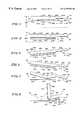
- FIG. 3is a diagrammatic view of the chair bed of FIG. 1 showing the chair bed in the bed position including a mattress having an upwardly-facing sleeping surface held a predetermined first distance above the floor, the deck being in an initial bed position supporting the sleeping surface in a generally planar configuration, and the foot section being a first length;
- FIG. 4is a diagrammatic view showing the chair bed in a low position
- FIG. 5is a diagrammatic view showing the chair bed in a Trendelenburg position
- FIG. 6is a diagrammatic view showing the chair bed in a reverse Trendelenburg position
- FIG. 7is a diagrammatic view showing the chair bed in an intermediate position having a head end of a head section of the deck pivoted slightly upward from the initial position of the deck, a seat section positioned to lie in the horizontal plane defined by the seat section in the initial position of the deck, and the foot section being inclined slightly so that the foot end of the foot section lies below the position of the foot section when the deck is in the initial position of the deck;
- FIG. 8is a diagrammatic view showing the chair bed in the chair position with the head end of the head section pivoted upwardly away from the seat section to a back-support position, the seat section lying generally horizontal as in the initial deck position, the thigh section being raised upwardly, the foot section extending downwardly from the thigh section and being a second shorter length, and the portion of the mattress over the foot section being deflated;
- FIG. 9is a block diagram illustrating the electronic control modules of the present invention connected in a peer-to-peer network configuration and illustrating the additional system components which are coupled to the various modules by discrete electrical connections;
- FIG. 10is a diagrammatical view illustrating the electrical connection from the communication network cable to a selected module and illustrating a coupler between a pair of network connectors to facilitate adding another module to the network;
- FIG. 11is a schematic block diagram illustrating the electronic components of a bed articulation control module
- FIG. 12is a schematic block diagram illustrating the electrical components of the scale instrument module
- FIG. 13is a schematic block diagram illustrating the mechanical and electrical components of the bed position sense and junction module
- FIG. 14is a schematic block diagram illustrating the components of the left and right standard caregiver interface module for either the left siderail or the right siderail;
- FIG. 15is a diagrammatical view of the lockout switches on the siderail control panel to prevent movement of selected sections of the bed.
- FIG. 16is a schematic block diagram illustrating the mechanical and electrical components of the graphical caregiver interface module
- FIGS. 17 and 18are flow charts illustrating details of the automatic module recognition feature of the graphical caregiver interface module
- FIG. 19is a flow chart illustrating the steps performed by the communications module for automated data collection from the other modules connected to the communication network of the bed;
- FIG. 20is a diagrammatical view illustrating a patient status module and a gateway module of the present invention.
- FIG. 21is a diagrammatical view illustrating details of a patient charting module of the present invention.
- FIG. 1A chair bed 50 in accordance with the present invention having a head end 52 , a foot end 54 , and sides 56 , 58 is illustrated in FIG. 1 .
- head end 52will be used to denote the end of any referred-to object that is positioned to lie nearest head end 52 of chair bed 50 .
- foot end 54will be used to denote the end of any referred-to object that is positioned to lie nearest foot end 54 of chair bed 50 .
- Chair bed 50includes a base module 60 having a base frame 62 connected to an intermediate frame module 300 as shown in FIG. 1 .
- Casters 70 , 72 , 74 and 76support the base frame 62 .
- An articulating deck/weigh frame module 400is coupled to intermediate frame module 300 .
- Side rail assemblies 800 , 802 , 804 , 806 and an extended frame module 610 having a swinging foot gate 622are coupled to articulating deck/weigh frame module 400 .
- a mattress 550is carried by articulating deck/weigh frame module 400 and provides a sleeping surface or support surface 552 configured to receive a person (not shown).
- Chair bed 50is manipulated by a caregiver or by a person (not shown) on sleeping surface 552 using hydraulic system module 100 so that mattress 550 , an intermediate frame 302 of intermediate frame module 300 , and an articulating deck 402 of articulating deck/weigh frame module 400 assume a variety of positions, several of which are shown diagrammatically in FIGS. 3-8.
- Articulating deck 402includes a head section 404 , a seat section 406 , a thigh section 408 , and a foot section 410 .
- Mattress 550rests on deck 402 and includes a head portion 558 , a seat portion 560 , a thigh portion 562 , and a foot portion 564 , each of which generally corresponds to the like-named portions of deck 402 , and each of which is generally associated with the head, seat, thighs, and feet of the person on sleeping surface 552 .
- Chair bed 50can assume a bed position having deck 402 configured so that sleeping surface 552 is planar and horizontal, defining an initial position of deck 402 as shown in FIG. 1 and as shown diagrammatically in FIG. 3 .
- sleeping surface 552is a predetermined first distance 566 above the floor.
- Chair bed 50can also be manipulated to assume a low position shown diagrammatically in FIG. 4 having deck 402 in the initial position and having sleeping surface 552 a predetermined second distance 568 above the floor, the second distance 568 being smaller than first distance 566 .
- the foot deck section 410 of the articulating deck 402includes a pivoting portion 466 and a contracting portion 462 . Foot deck section 410 has a first length 465 when the deck 402 is in the initial position.
- Chair bed 50can be moved to a Trendelenburg position shown diagrammatically in FIG. 5 having deck 402 in a planar configuration and tilted so that head end 52 of sleeping surface 552 is positioned to lie closer to the floor than foot end 54 of sleeping surface 552 .
- Chair bed 50can also achieve a reverse Trendelenburg position shown diagrammatically in FIG. 6 having deck 402 in a planar configuration and tilted so that foot end 54 of sleeping surface 552 is positioned to lie closer to the floor than head end 52 of sleeping surface 552 .
- chair bed 50is convertible to a sitting or chair position shown in FIG. 2 and shown diagrammatically in FIG. 8 .
- head end 52 of head section 404 of deck 402is pivoted upwardly away from intermediate frame 302 to a back-support position providing a pivotable backrest so that head section 404 and intermediate frame 302 form an angle 512 generally between 55 and 90 degrees.
- Seat section 406 of deck 402is positioned to lie generally horizontally as in the initial position
- foot end 54 of thigh section 408is slightly upwardly inclined
- foot section 410 of deck 402extends generally vertically downwardly from thigh section 408 and has a length 464 that is shorter length 465 than when deck 402 is in the initial position.
- Foot portion 564 of mattress 550is inflatable and is in a deflated condition when chair bed 50 is in the chair position.
- Foot portion 564 of mattress 550is thinner and shorter when deflated than when inflated.
- Chair bed 50is capable of assuming positions in which head, thigh, and foot sections 404 , 408 , 410 of deck 402 are in positions intermediate to those shown in FIGS. 3 and 8.
- chair bed 50can assume an intermediate position shown diagrammatically in FIG. 7 having head end 52 of head section 404 of deck 402 pivoted slightly upwardly from the initial position, seat section 406 positioned to lie in the same generally horizontal plane as in the initial position, foot end 54 of thigh section 408 raised slightly upwardly from the initial position, and foot section 410 being inclined so that foot end 54 of foot section 410 lies below head end 52 of foot section 410 .
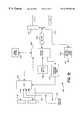
- FIG. 9is a block diagram illustrating the plurality of electronic control modules for controlling operation of the hospital bed.
- the plurality of modulesare electrically coupled to each other using a twisted pair network channel in a peer-to-peer configuration.
- the peer-to-peer networkextends between first and second network terminators 1012 and 1013 .
- the network connectionsare illustrated by the solid black lines in FIG. 9 .
- Discrete connections to each of the modulesare illustrated by the dotted lines in FIG. 9 .
- the bold line of FIG. 9illustrates an AC power connection.
- Network terminator 1012is coupled to an air supply module 1014 .
- Air supply module 1014is coupled via the network cable to accessory port module 1016 .
- Accessory port module 1016is coupled to the bed articulation control module (BACM) 1018 .
- BACM 1018is coupled to a communications module 1020 .
- Communications module 1020is coupled to scale instrument module 1022 .
- Scale instrument module 1022is coupled to surface instrument control module 1024 .
- Surface instrument module 1024is coupled to position sense and junction module 1026 .
- Position sense module 1026is coupled to the network terminator 1013 .
- a left side standard caregiver interface module 1028is also coupled to the network by a connection in position sense module 1026 .
- the right side standard caregiver interface module 1030 and the graphic caregiver interface module 1032are also coupled to the network using a connection in the position sense module 1026 .
- modulescan be rearranged into a different position within the peer-to-peer network.
- the modulesare configured to communicate with each other over the network cable without the requirement of a master controller. Therefore, modules can be added or removed from the network without the requirement of reprogramming or redesigning a master controller.
- the networkrecognizes when a module is added to the network and automatically enables a control interface such as graphic caregiver interface module 1032 to display specific module controls for the added module. This eliminates the requirement for controls on individual modules.
- the module recognition featureis discussed in detail below.
- Each moduleis connected to its appropriate sensors and actuators so that it can perform its dedicated function.
- the followingis a brief description of each electronic module:
- Power for the communication networkis supplied by a power supply and battery charge module 1062 .
- Power supply 1062is coupled to a power entry module 1063 and an AC main plug 1065 .
- Power Supply/Battery charge module (PSB) 1062converts the AC Mains input 1065 to DC levels to be used by the electronic modules.
- PSB 1062contains filtering for the AC Mains 1065 at the Mains entry point 1063 .
- the PSB 1062also provides power for limited bed functionality upon removal of the AC Mains power input via a battery 1067 .
- the PSB 1062contains an automatic battery charging circuit with output to indicate battery status (i.e., battery dead, battery low, battery OK).
- PSB 1062also controls the hydraulic pump 1055 .
- Bed Articulation Control Module (BACM) 1018The BACM 1018 primarily controls the hydraulic system used to articulate the bed. BACM 1018 accepts inputs from various user interfaces located throughout the bed to control bed articulations. This control input is qualified with a position sensing input representing the actual locations of the bed deck sections, along with patient lockout controls, to determine whether the bed should articulate. The BACM 1018 is present in every bed. BACM includes a real time clock circuit to set the time for various other modules.
- Position Sense module 1026detects the angles of all the appropriate bed deck sections. In addition, it interfaces to the bed exit detect, and the four (4) side rail UP sensors. The position sense module 1026 outputs this information to the network. These functions may be incorporated into the BACM 1018 and Bed-Side Communications Interface module 1020 . The position sense module 1026 also provides the interconnections of the bed network and hospital communications links to the siderail standard caregiver interface 1028 and 1030 modules.
- the siderailswill contain standard caregiver interface modules 1028 and 1030 consisting of input switch controls, output status indicators, and an audio channel.
- the standard caregiver interface modules 1028 and 1030are coupled to patient control mechanisms for bed articulations, entertainment, surface, lighting, Bed Exit, and Nurse Call.
- Scale Instrument Module 1022translates the signals from the embedded load beams into actual weight measured on the weigh frame. Scale module 1022 outputs this weight to the Graphic Caregiver Interface Module (GCI) 1032 for display purposes. This weight is also available to the communications module 1020 for transmittal to the hospital information network. Scale module 1022 includes Bed Exit and weight gain/loss alarm detection capability.
- GCIGraphic Caregiver Interface Module
- Surface Instrument Module 1024controls the dynamic air surface. It will accept input from the GCI 1032 to dictate system performance characteristics. Surface module 1024 uses the GCI 1032 to display outgoing system information. Surface instrument module 1024 also interfaces with the air supply module 1014 to control the air handling unit 1046 .
- Sequential Compression DeviceThis module will control the optional compression boots. It will use the GCI 1032 for interfacing to the caregiver.
- GCI 1032controls the scale 1022 and surface module 1024 (including SCDs). In addition, GCI 1032 provides control input and text and graphic output capability for future design considerations. GCI 1032 utilizes a graphic display along with a software menu structure to provide for full caregiver interaction.
- Communications module 1022is the gateway between the patient's environment controls and bed status information residing on the bed, and the hospital information/control network.
- Bed Exit Sensor (BES) 1069exists on non-scale beds.
- the BESconnects to the position sense module 1026 to detect a patient bed exit.
- Brake-Not-Set Sensor (BNS) 1056detects the state of the Brake/Steer Pedal. It is connected to the BACM 1018 .
- Bed-Not-Down Sensor (BND) 1058detects if the bed is fully down (both Head and Foot Hilo). It is connected to the BACM 1018 .
- SUD 1071consists of four switches to detect the secure UP position of the side rails.
- the SUD 1071is connected to the position sense module 1026 .
- Night Light 1073is a stand alone unit providing the night light function. It is powered by low voltage AC coming from the Power Supply/Battery module 1062 .
- Pendant 1048provides for bed articulation control input through accessory port module 1016 .
- Patient Assist Arm Control 1050is a functional equivalent of the standard caregiver interface modules 1028 and 1030 controls in a different physical embodiment.
- the assist armincludes a control pad coupled to the accessory module 1016 .
- the air supply module 1014 , the bed articulation control module 1018 , the power supply module 1062 , and the power entry module 1063are all coupled to the base frame of the hospital bed.
- the communications module 1020 , the scale instrument 1022 , and the remote information interface 1124are all coupled to the intermediate frame.
- the left standard caregiver interface 1028 and patient interfaces 1154 and 1156are all coupled to the left siderail.
- the right standard caregiver interface 1030 and patient interfaces 1158 and 1160are all coupled to the right siderail.
- Graphical caregiver interface module 1032may either be coupled to the left siderail or the right siderail.
- the position sense module 1026 and surface module 1024are each coupled to the weigh frame. It is understood that the position of each module can be changed.
- FIG. 10diagrammatically illustrates how the various modules are added and removed from the network.
- the electronic networkuses an Echelon LonTalk serial communications protocol for module to module communication in the bed.
- the cable 1034 illustrated in FIG. 10contains power and a twisted pair connection.
- the preferred protocolis RS-485 with a transmission speed of 78 kbs.
- the cable 1034is provided with connectors 1036 .
- Extra connectors 1036are provided for module additions.
- a coupler 1038is provided to interconnect adjacent connectors 1036 .
- the coupler 1038is removed and connectors 1036 are coupled to mating connectors 1042 of the module 1040 .
- Connectors 1042are electrically coupled within the module 1040 as illustrated by dotted line 1044 .
- air supply module 1014is coupled to an air handling unit 1046 by a discrete electrical connection. Air supply module 1014 controls compressor 1046 to inflate and deflate the mattress surface of the bed as discussed in detail below (or in main application).
- the accessory port module 1016provides connections to the network for a pendant 1048 , an assist arm control 1050 , or a diagnostic tool 1052 .
- Pendant 1048is a hand held control unit which is movable from bed to bed. Therefore, pendant 1048 may be coupled and uncoupled from accessory port module 1016 to control various functions of the bed.
- the accessory port module 1016can communicate with BACM 1018 to control movement of the bed.
- Assist arm controls 1050provide input to accessory port module 1016 from a control pad coupled to an assist arm extending out over the patient support surface of the bed.
- the assist arm 1050can be used to control movement of the bed, as well as for other desired functions.
- the pendant 1048 and assist arm control 1050may include all the controls of the right and left standard caregiver interface modules discussed below.
- Diagnostic tool 1052is used for servicing the bed, either at the bed site or from a remote location.
- a modemis coupled to accessory port module 1016 to provide a telephone line connection to the hospital bed. This permits information related to the bed from any module to be retrieved from the peer-to-peer network at a remote location. For instance, the amount of time that the surface of the bed is in use may be detected at the remote location through the modem for billing purposes.
- the diagnostic tool 1052permits a remote operator to interrogate every module of the electrical control network.
- the diagnostic tool 1052checks application dependent parameters, runs each of the modules through a test procedure, and fully accesses all network information.
- Diagnostic tool 1052may be a hand held tool such as a lap top computer which is coupled directly to accessory port module 1016 .
- a remote computercan be coupled to accessory port 1016 with the modem link to provide a data link to the network.
- a Voice MateTM control system available from Hill Rom, Inc.may also be coupled to accessory port module 1016 to control the bed
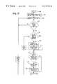
- the bed articulation control module (BACM) 1018is the module that controls movement of the bed.
- BACM 1018controls actuation of a plurality of solenoids 1054 which open and close valves coupled to hydraulic cylinders to move the articulating deck sections of the hospital bed relative to each other.
- BACM 1018is also coupled to a Break Not Set sensor 1056 and a Bed Not Down sensor 1058 .
- the BACM 1018receives an input signal from the network requesting movement of the bed to a predetermined position, the BACM 1018 first reads the position of the bed provided from position sense module 1026 . If movement of a portion of the bed is necessary, BACM 1018 checks for a lockout signal from the left and right standard caregiver interface modules 1028 and 1030 . If the lockouts are not set, BACM 1018 controls activation of the selected solenoid 1054 and then BACM 1018 turns on the hydraulic pump 1055 (gravity may also be used if appropriate) to actuate a selected cylinder if necessary.
- BACM 1018includes a neuron controller 1060 .
- neuron controller 1060is a MC143150FU echelon neuron networking microprocessor available from Motorola. Controller 1060 is coupled to the network through an RS-485 transceiver 1061 .
- BACM 1018operates to move a plurality of solenoids 1054 in a hydraulic manifold to open and close control valves coupled to the hydraulic cylinders and articulate the bed based on various network commands received from the peer-to-peer network.
- Neuron controller 1060receives commands from the right and left siderail standard caregiver interface modules 1028 and 1030 , the graphic caregiver interface 1032 , or from another input device to articulate the bed.
- Neuron controller 1060also receives other information from the network regarding the position of the head, seat, thigh, and foot deck sections of the articulating deck of the bed. Therefore, neuron controller 1060 controls the solenoids and pump to stop articulating the bed as a limit is reached or when the particular bed section reaches its desired or selected position.
- Both the articulating deck of the bed and the height of the deckare controlled by the BACM 1018 .
- the BACM 1018Upon receiving a bed function command from the network, the BACM 1018 energizes the appropriate solenoids and provides a control signal to the Power Supply/Battery Module 1062 illustrated in FIG. 9 to power the hydraulic pump, if necessary.
- BACM 1018may use bed position information provided by the remotely mounted bed position transducers. Alternatively, the position of the various sections of the articulating deck may be supplied to BACM 1018 by the position sense module 1026 .
- BACM 1018also instructs air supply module 1014 and surface control module 1024 via the network to partially deflate a seat section and a foot section of the mattress when the bed moves to a chair position.
- BACM 1018also receives lockout information from the siderail standard caregiver interface modules 1026 and 1028 to determine whether or not a particular section of the articulating deck should move.
- Neuron controller 1060executes code stored in EPROM 1064 .
- EPROM 1064is a 27C256-70 EPROM available from AMD.
- BACM 1018uses a pulse width modulation (PWM) control system to minimize the current draw required to actuate the solenoids 1054 .
- PWMpulse width modulation
- Conventional control systemssimply turn the solenoid 1054 full on or full off and, as the voltage varies, current consumption goes up and down accordingly.
- PWMpulse width modulation
- BACM 1018controls the power that is applied to the solenoid 1054 to maintain substantially the same current level to minimize power consumption.
- Neuron controller 1060controls a timing generator 1066 through a memory map address decoder 1068 .
- Memory map address decoder 1068provides a signal to timing generator 1066 on line 1070 to start PWM and provides a signal on line 1072 to timing generator 1066 to stop PWM.
- Neuron controller 1060provides a 5 or 10 MHz clock signal to timing generator 1066 on line 1074 .
- Timing generator 1066provides six different time periods in which to actuate one of six pairs of solenoids 1054 used to control the valves of the hydraulic cylinders. Each time period is about 50 milliseconds. Only one solenoid 1054 can be pulled during any one time period. This minimizes the maximum current draw on the power supply or battery at any given time. It is understood that a different number of solenoid pairs may be controlled in accordance with the present invention. The number of time periods and the time period intervals may be changed, if desired. In the illustrated embodiment, six pairs of solenoids are controlled by the BACM 1018 .
- One solenoid of each pairis used to open a first valve to control movement of a deck section in a first direction, and the other solenoid of each pair is used to open a second valve to control movement of the particular section in an opposite direction. Therefore, a pair of solenoids is provided for the head section cylinder, the foot section cylinder, the foot Hi Lo cylinder, the head Hi Lo cylinder, the knee section cylinder, and the foot retracting section cylinder.
- Timing generator 1066supplies a PWM enable signal on line 1076 to a solenoid PWM select logic control circuit 1078 . Timing generator 1066 also provides time division terms to PWM control circuit 1078 on line 1080 .
- Neuron controller 1060can provide three separate commands for each solenoid.
- the commandsinclude an extend command, a retract command, and a pull-in command.
- the extend commandis used to select the correct solenoid which when energized will extend the appropriate cylinder.
- Steady-state control of the FET which powers the solenoidsis pulsed ON and OFF at the PWM rate.
- the retract commandis used to select the opposing solenoid which when energized retracts the cylinder. It too is turned ON and OFF at the PWM rate.
- the pull-in commandoverrides the PWM control circuit.
- Data including the control commands (pull-in, extend, or retract) for a selected solenoid 1054 transmitted from the neuron controller 1060is written to buffer register 1084 .
- the commandsare shifted into a holding register 1088 . Therefore, asynchronous information is received in buffer register 1084 .
- This asynchronous informationis synchronized into the holding register 1088 using a timing generator pulse on line 1094 .
- the timing signal 1094synchronizes the pull-in latch 1082 in buffer register 1084 and the pull-in latch 1086 in the holding register 1088 with the timing generator 1066 .
- Timing signal 1094also synchronizes the solenoid “extend” latches 1096 and 1098 and the solenoid 1054 “retract” latches 1100 and 1102 with the timing generator 1066 .
- the PWM select logic control circuit 1078receives commands from the holding register 1088 and provides signals to drive a discrete FET through FET drivers 1090 during each timing interval of the PWM timing generator 1066 .
- Driver 1090pulls the selected solenoid 1054 down to ground and applies a voltage across the selected solenoid 1054 to control the solenoid.
- a voltage clamp 1104is coupled to each of the solenoids 1054 . When power is removed from a particular FET an inductive signal is supplied to the solenoids 1054 . Voltage clamp 1104 clamps the inductive signal to the voltage rail. Therefore, voltage clamp 1104 provides voltage spike suppression.
- a diagnostic block 1106also receives current signals related to each pair of solenoids 1054 from voltage clamp 1104 on line 1105 . Only one solenoid 1054 in each pair can be controlled or actuated at any given time. Diagnostic block 1106 also receives a data command signal from neuron controller 1060 on line 1108 indicating the particular solenoids 1054 which are designated by the controller 1060 for activation. Therefore, diagnostic block 1106 compares the actual information received from the solenoid 1054 pairs to the data received on lines 1108 . If the actual solenoid 1054 current does not match the desired solenoid 1054 activation data from controller 1060 , diagnostic block 1106 sends a signal to neuron controller 1060 on line 1110 .
- a signal on line 1110actuates a signal on supervisory line 1112 coupled to a master FET 1114 to turn off the master FET 1114 and shut off power to all the solenoids 1054 .
- the master FET 1114is coupled in line with all twelve solenoids 1054 . Therefore, supervisory FET must be turned on to provide power to any one of the solenoids 1054 .
- a current sense resister 116is coupled to the FET drivers 1090 .
- the current sense resister 116is coupled to the first input terminal of a comparator 1118 .
- a second input terminal of comparator 1118is coupled to a reference voltage.
- the output of comparator 1118provides PWM feedback signal to timing generator 1066 on line 1120 .
- the current sense resister 116measures the current in each of the six time slots used for controlling the solenoids 1054 .
- the signal on line 1120adjusts the timing generator 1066 to control the pulse width of the driver signal. Therefore, if too much current is being drawn, then timing generator 1066 shortens the width of the driver pulse in order to bring the current down.
- communications module 1020provides an interface needed for bed-to-hospital or hospital-to-bed information transfer.
- Communications module 1020is a gateway between the bed network and the hospital information/control network.
- Communications module 1020is connected to a standard side-com interface 1122 .
- Interface 1122also provides direct hard wired links between the nurse call switches on the side rails of the bed and the hospital priority nurse call network. Signals from these nurse call switches can also be sent over the network.
- a switch input portis provided to accept a bed exit signal coming from a bed exit sensor.
- Interface 1122supports all existing discrete wire protocols. Interface 1124 will support newly defined serial protocols, both to hospital network and other hospital room equipment. Any other hospital room equipment can use the GCI module 1032 as its user interface control module.
- Communications module 1020also provides entertainment functions. Television, radio, or the like may be controlled by communications module 1020 based on input/output signals received/sent from the left or right siderail standard caregiver interface modules 1028 and 1030 over the network or via discrete connections.
- Communications module 1020is directly coupled to the hospital information electrical network to transmit and receive signals from a remote location. Communications module 1020 receives weight information from scale instrument module 1022 . Communications module also receives surface setting information, including pressures and other parameters from surface instrument module 1024 . Communications module 1020 also receives bed position information from position sensing module 1026 . In addition, communications module 1020 can receive all information travelling on the network.
- the hospital networkcan drive a display on the graphic caregiver interface 1032 using signals transmitted from the remote location through a remote information interface 1124 , to communications module 1020 , and then to graphic caregiver interface 1032 over the network. Therefore, communications module 1020 provides an interactive data link between the remote location and the graphic caregiver interface module 1032 . Requests for weight acquisition can be automatically sent from a remote location through remote information interface 1124 and communications module 1020 . Communications module 1020 then communicates with scale instrument 1022 to determine the weight and then transmits the weight to the remote location via the remote information interface 1124 .
- the scale instrument module 1022receives input signals from load beams coupled to a weigh frame of the bed. Specifically, scale instrument module 1022 receives input signals from a left head load beam 1126 , a right head load beam 1128 , a right foot load beam 1130 , and a left foot load beam 1132 . The scale module 1022 transmits weight information and operation parameters to the GCI module 1032 and communications module 1020 . Load beams 1126 , 1128 , 1130 , and 1132 are bolted to the intermediate frame. The articulating deck and weigh frame module is then bolted to the load bearing ends of the load beams. Any item attached to or resting on the articulating deck and weigh frame will be weighed by the load beams.
- Scale instrument module 1022receives information from the network via a nurse caregiver interface unit or a graphic caregiver interface module 1032 .
- the scaleacquires data from the load beam transducers 1126 , 1128 , 1130 , and 1132 and automatically factors in the tare weight to calculate a patient weight.
- Scale module 1022transmits an output signal to the network representing the patient weight.
- Scale module 1022can detect bed exit and alert the hospital via the communications module 1020 and remote information interface 1124 .
- Scale module 1022also provides a weight change alarm. Scale module 1022 accepts a set point weight from the network. Scale module 1022 detects if a patient's weight change has exceeded or dropped below a preset level from the initial set point weight. If a preset weight change has occurred, scale module 1022 provides an alarm message to the network. Scale module 1022 stores all data critical to the functioning of the scale in non-volatile memory. Scale module 1022 has built in diagnostic capability to detect hardware integrity and data integrity.
- scale module 1022Details of scale module 1022 are illustrated in FIG. 12 .
- the four load cells 1126 , 1128 , 1130 , and 1132are coupled to a four channel analog to digital converter 134 .
- analog to digital converteris a CS5516,4 MHz analog to digital converter available from Crystal Semiconductor.
- Analog to digital converter 134converts analog signals from the load cells 1126 , 1128 , 1130 , and 1132 into digital signals and inputs the signals into the echelon neuron controller 1136 .
- Neuron controller 1136is a MC143150,10 MHz networking microprocessor available from Motorola.
- Controller 1136executes code stored in an EPROM 1138 .
- EPROM 1138is a 32K ⁇ 8, model 27HC256 EPROM available from AMD.
- Neuron controller 1136stores calibration data related to each of the load cells 1126 , 1128 , 1130 , and 1132 either in its internal memory or in external EEPROM 1140 . Calibration data is necessary because each load beam 1126 , 1128 , 1130 , and 1132 has slightly different gain or offset constant associated with it.
- Calibration/excitation relay 1142transmits the calibration data from neuron controller 1136 to analog to digital converter 1134 .
- Two connectors 1148 and 1150are provided to couple scale module 1022 to the peer-to-peer communication network. Connector 1148 is hard wired to connector 1150 .
- An RS-485 transceiver 1149is coupled between connectors 1148 and 1150 and controller 1136 .
- Transceiver 1149takes logic inputs and outputs and converts them to RS-485 level signals for the network. For each of the modules on the peer-to-peer network, a connector such as connector 1148 is hard wired to another connector such as connector 1150 that goes onto the next node or module in a daisy chain configuration. Scale module 1022 also includes a +5VDC regulated power supply 1152 .
- the surface instrument module 1024is provided for controlling operation of the mattress or support surface. Details of this module are discussed below with reference to the surface design (or in main application).
- the bedincludes position transducers mounted throughout the bed to sense any needed positions of individual bed sections for articulation and caregiver interface purposes.
- the position sense module 1026also interfaces a Side Rail Up Detect Sensor, and a Bed Exit Sensor.
- the position transducersare discrete tilt sensors on various deck sections of the bed.
- the sensorsinclude a trendelenburg limit sensor at 13° relative to earth, a reverse trendelenburg sensor at ⁇ 13° relative to earth, and a bed-level at 0° relative to earth.
- the articulating deck sectionsinclude position transducers which are also discrete tilt sensors.
- the tilt sensorsare model A1 ⁇ 2 sensors available from AEC.
- the patient head limit sensordetects the head section at 55° relative to earth.
- the head contour limit sensordetects the head section at 30° relative to earth.
- the knee contour limitdetects the knee section at 12° relative to earth.
- the patient foot limitdetects the position of the foot section at 30° relative to earth.
- the sensor inputsare coupled to the position sense module 1026 .
- the sensor input signalsare signed conditioned using a RC filter 1154 .
- the output of RC filter 1154is coupled to a neuron controller networking microprocessor 1156 .
- An output from controller 1156drives a local alarm 1158 .
- Input power on line 1160is coupled to a regulated power supply 1162 which produces a +5V output.
- the output from power supply 1162is coupled to neuron controller 1156 and to a network transceiver 1164 .
- the position transducersillustratively switch from a logic high to a logic low upon detection of the particular angle relative to earth.
- Controller 1156transmits and receives network information through transceiver 1164 .
- Network transceiver 1164is coupled to a first network connector 1165 via lines 1166 .
- Position sense module 1126also provides the connection points to the network for the left and right standard caregiver interface modules 1028 and 1030 .
- Network connector 1165also coupled to a left siderail network connector 1170 which is coupled to the left siderail standard caregiver interface module 1128 .
- Left siderail connector 1170is coupled to a right siderail connector 1172 by lines 1171 .
- Connector 1172is coupled to a right siderail standard caregiver interface module 1030 .
- Connector 1172is also coupled to a second network connector 1173 by lines 1175 . Therefore, position sense module 1026 is also a junction module for connection to the left and right side rail standard care giver interface modules 1028 and 1030 .
- neuron controller 1156interprets the sensor signals received from RC filter 1154 and sends an output signal indicative of the state of each sensor to the network through network transceiver 1164 .
- Network transceiver 1164is a RS-485 protocol transceiver.
- Alarm 1158contains a piezo device so that any alarms on the bed that are transmitted through the network turn on the piezo alarm on the position sense module 1026 . These alarms may include bed exit, patient weight gain, weight loss, surface pressure loss, or other desired alarms. Alarm 1158 can also be used to alert an operator when catastrophic failures are detected in the bed by the diagnostic tools.
- the left and right standard caregiver interface modules 1028 and 1030are substantially identical.
- the left standard caregiver interface module 1028is coupled to patient controls including an articulation and entertainment interface in the left siderail as illustrated at block 1154 of FIG. 9 .
- Standard caregiver interface module 1028is also coupled to a surface patient interface on the left side rail as illustrated at block 1156 .
- the standard caregiver interface module 1030 for the right sideis coupled to articulation and entertainment patient interface module on the right siderail as illustrated at block 1158 .
- the right standard caregiver interface module 1030is also coupled to a surface patient interface caregiver interface on the right side rail as illustrated at block 1160 .
- the standard caregiver interface moduleincludes an echelon controller 1162 which is a networking microprocessor. Echelon controller 1162 is coupled to a +5.0V supply voltage from power supply 1164 . Echelon controller 1162 is also coupled to a network transceiver 1166 . Transceiver 1166 is an RS-485 protocol transceiver. Transceiver 1166 couples controller 1162 to the peer-to-peer communication network as illustrated at line 1168 . A network connection for the graphic caregiver interface module 1032 is provided at line 1170 for both the left and right standard caregiver interface modules 1128 and 1030 . Graphic caregiver interface module 1032 can be connected on either the left or right side of the bed.
- Echelon controller 1162interprets the network messages.
- Network controller 1162also detects switch activation from the articulation and entertainment patient interface 1154 and the surface patient interface 1156 and transmits output signals to the network on line 1168 .
- the switchescan be dead function switches, lockout switches, bed exit switches, nurse call backlit switches, and so on.
- Controller 1162drives a LED driver 1172 to light indicator LEDS 1174 related to various bed status functions, such as bed-not-down, brake-not-set, battery low, and service required.
- the LED driver 1172is also coupled to a backlighting switch 1176 of the articulation and entertainment patient interface 1154 .
- Backlighting switch 1176is coupled to backlighting LEDs 1178 .
- Backlighting switch 1176is also coupled to backlighting LEDs 1180 on the surface patient interface 1156 .
- the standard caregiver modules 1028 and 1030connect all the caregiver interfaces switches in a row/column type architecture to provide a 4 ⁇ 10 matrix.
- a keyboard row selection logic circuitis used to detect switch presses as illustrated at block 1182 .
- the standard caregiver interface (SCI) modules 1028 and 1030include the network circuitry for interfacing all caregiver and patient siderail caregiver interfaces to the communication network.
- the patient caregiver interfacesare separated into modules which can be connected to the SCI module 1028 or 1030 in a modular fashion.
- Each SCI module 1028 and 1030includes bed articulation switches 1184 . These include head up, head down, knee up, knee down, foot up, foot down, bed up, bed down, chair in, chair out, trendelenburg, and reverse trendelenburg. In the case of a switch closure, a signal is periodically output to the network until the opening of the switch occurs.
- the SCI modules 1028 and 1030further include lockout switches 1186 as discussed below, bed exit switches 1188 , nurse call switches 1190 , and backlighting switches 1192 . Control buttons for the switches 1184 , 1186 , 1188 , 1190 , and 1192 are typically on an outside portion of the siderail for use by a nurse.
- the articulation and entertainment patient interface 1154also includes a nurse call switch 1194 , interactive TV switches and a light switch 1196 , and bed articulation switches 1198 .
- Surface patient interface 1156includes nurse call LEDs 1200 , mattress switches 1202 , and a nurse call switch 1204 .
- the lockout control switchesare located on the left and right siderail control interfaces.
- the lockout controlincludes a global enable lockout activation switch 1205 which must be pressed in order to activate any of the other lockout toggle switches for the foot control lockout 1207 , the knee control lockout 1209 , the head control lockout 1211 , or the lockout for all controls at 1213 .
- This double lockout activationreduces the likelihood of the accidental deactivation of one of the lockout control switches. Therefore, the global enable switch 1205 must be pressed in order to turn any of the other lockout controls on or off.
- the global enable switch 1205automatically deactivates after about 5 seconds of inactivity. After the global enable is deactivated, the lockout status cannot be changed. Since the caregiver controls are within reach of a patient, the global enable switch may be used to enable and disable both the patient and caregiver bed articulation control switches.
- a graphic caregiver interface (GCI) module 1032is illustrated in detail in FIG. 16 .
- the GCI module 1032provides an enhanced menu-driven caregiver input and output for bed articulation, scale, surface caregiver interface, and sequential compression device controller, and all other modules needing this type of user interface.
- the GCI module 1032includes a LCD display 1206 , which is illustratively a 320 ⁇ 240, model DMF 50081 available from Optrex. Display 1206 may also be a 320 ⁇ 240, model G321EX available from Seiko. Display 1206 outputs graphical information to the caregiver.
- a switch panel 1208permits the caregiver to input information into the GCI module 1032 .
- Switch panel 1208may be a series of discrete switches or an alpha/numeric keypad.
- Switch panel 1208is coupled to a connector 1210 .
- Connector 1210is coupled to an input of CPU 1212 .
- CPU 1212is illustratively an 80C188XL, 10 MHz CPU available from Intel.
- the input device for the caregivermay also be an encoder 1214 which is coupled to a connector 1216 .
- Connector 1216is coupled to CPU 1212 .
- encoder 1214is a rotary encoder.
- Transceiver 1220is coupled to a +5 VDC regulated power supply 1222 .
- Transceiver 1220is also coupled to a +12VDC regulated power supply 1224 .
- Transceiver 1220is coupled to an echelon neuron controller networking microprocessor 1226 .
- Controller 1226is illustratively an AMC143120, 10 MHz networking microprocessor available from Motorola.
- Neuron controller 1226is coupled to an I/O test port 1228 .
- Controller 1226is also coupled to CPU 1212 .
- Software code for operating CPU 1212is stored in an EPROM memory 1230 .
- memory 1230is a 512K ⁇ 8 flash EPROM memory. Data is stored in static RAM memory 1232 . Illustratively, memory 1232 is a 128K ⁇ 8 memory chip. Additional memory is provided in a 2K ⁇ 8 EEPROM 1234 .
- An output from CPU 1212is coupled to a LCD backlight inverter 1236 .
- Backlight inverter 1236is coupled to LCD display 1206 by connector 1238 . Backlight inverter facilitates viewing of display 1206 in all types of room lighting. Inverter 1236 is configured to match the particular display 1206 selected.
- CPU 1212is also coupled to a LCD controller 1240 .
- LCD controller 1240drives the display 1206 through a connector 1242 .
- Controller 1240is coupled to a 32K ⁇ 8 static video RAM 1244 .
- the controller 1240stores the image in VRAM 1244 and then continuously refreshes the display screen 1206 with the image stored in the VRAM 1244 .
- Contrast of the display 1206is controlled by software contrast adjustment as illustrated at block 1246 .
- a LCD bias supply voltage at block 1248is coupled to connector 1242 .
- Supply 1248converts a +5V input or a +12V input into a ⁇ 22V output.
- An external watchdog timer 1250monitors CPU 1212 . If the CPU 1212 does not pulse the particular line on a periodic basis, timer 1250 resets the system.
- GCI module 1032also includes a diagnostic port 1252 .
- Diagnostic port 1252is coupled to CPU 1212 through a serial port 1254 .
- Serial port 1254is a RS-232 UART. Therefore, a laptop may be connected at port 1252 to interrogate the CPU 1212 .
- CPU 1212can access and send information to the network through controller 1226 .
- the GCI module 1032provides an enhanced menu-driven caregiver input and output control for bed articulation, scale, surfaces, sequential compression devices, and all other modules needing this user interface capability.
- the GCI module 1032is intended to be a drop in replacement for Scale/Surface Nurse Control Unit.
- GCI module 1032interacts with scale module 1022 . Specifically, GCI module 1032 can transmit a request for patient weight to the scale module 1022 . In addition, the GCI module 1032 can also zero the scale and perform other scale module functions.
- GCI module 1032stores predetermined graphics data and caregiver interface data in memory 1230 . This predetermined graphics data is stored in the GCI module 1032 at the time of production. Additionally, other modules on the peer-to-peer communication network can download screen formats to the GCI module into static RAM 1232 . The GCI module then retrieves the stored graphic screen formats either from memory 1230 or static RAM 1232 and displays the output on display 1206 . By providing stored built-in graphics in memory 1230 , the GCI module 1032 can support products or other modules that may later be connected to the peer-to-peer communication network. By providing the stored predetermined graphic formats, the GCI module 1032 does not have to be updated each time a new module is added to the system. If the desired graphics format is not present in memory 1230 , then the newly added module must download the desired graphic formats into RAM 1232 at run time.
- the specific graphic formats stored in the GCI module 1032can include charting formats such as bar graphs, X-Y graphs, pie charts, etc., icons or pictures representing each of the modules in the communication network, or any other type of graphical format desired.
- Graphic formats for use by the modulesare stored in two different ways in the GCI module 1032 . Typically, these various graphic formats are stored in EPROM 1230 at the time of manufacture. In other words, these graphical formats are typically designed into the GCI module 1032 . If a particular GCI module 1032 does not include the desired graphic format stored in memory 1230 , then the particular graphic format for the new module added to the system is downloaded into the static RAM 1232 of GCI module 1032 after the bed is powered up.
- GCI module 1032does not include a X-Y graphic format in memory 1230 , this graphic format can be downloaded into RAM 1232 after the bed is powered up.
- this graphic formatcan be downloaded into RAM 1232 after the bed is powered up.
- the new moduletransmits only data to the GCI module 1032 during operation.
- the GCI module 1032uses the received data and the stored graphic format to produce an appropriate screen output on display 1206 .
- the particular moduletransmits only the X-Y data to the GCI module 1032 over the network.
- the GCI module 1032uses this data along with the stored X-Y graphic format to provide an output to display 1206 .
- Each new modulewill also download a particular icon representative of the new module for the menu-driven display 1206 of GCI module 1032 as discussed below.
- Updating of the graphic formats and menu information of the GCI module 1032can be accomplished in one of three ways.
- the particular graphic format and menu informationcan be downloaded into static RAM 1232 at power up of the bed.
- the graphic format and menu informationcan also be downloaded to EEPROM 1234 during installation of a new module.
- EPROM 1232can be changed to include the new graphic format and menu information at the time the new module is installed.
- FIGS. 17 and 18Details of the operation of GCI module 1032 for automatically recognizing and controlling newly added modules on the communication network are illustrated in FIGS. 17 and 18. Bed power up is illustrated at block 1260 .
- a graphics status flag and a menu saved status flagare both cleared at block 1262 . These flags provide an indication of whether a particular graphic format or menu information for the module must be downloaded to the GCI module 1032 .
- menu screenswill be provided on display 1206 . Therefore, if a particular module is selected using the GCI module 1032 , control options for that module will appear as menu items on display 1206 . Once a particular control option is selected, additional menu items for the selected control option may appear, and so on.
- GCI module 1032performs a system query at block 1264 .
- GCI module 1032first determines whether any modules are present on the communication network which use the GCI module 1032 as illustrated at block 1266 . If no modules are present on the network which use the GCI module 1032 , the GCI module 1032 returns to block 1264 .
- the system queryis carried out at predetermined time intervals.
- the GCI module 1032determines whether any of the modules need to download graphic formats to the GCI module 1032 as indicated at block 1268 . If no modules need to download graphic information, GCI module 1032 advances to block 1274 . If any of the modules need to download graphic formats, the graphic formats are downloaded to static RAM 1232 of GCI module 1032 as illustrated at block 1270 . The graphics status flag for the module is then updated as illustrated at block 1272 . The graphics status flag is initially generated at block 1266 during detection of any modules which use the GCI module. Therefore, after step 1270 the status flag 1272 indicates that all the graphic format data for the particular module is now stored on the GCI module 1032 .
- GCI module 1032next determines whether any of the modules need to download menu structure information to the GCI module. If not, GCI module 1032 advances to block 1280 in FIG. 18 . If any of the modules need to download menu structure information, the appropriate menu structure information is downloaded to the static RAM 1232 of GCI module 1032 . This menu structure information provides the appropriate menu-driven control for each module. For instance, once the module icon is selected using the switch panel 1208 or encoder 1214 of the GCI module 1032 , the GCI module 1032 automatically displays a menu screen of options on display 1206 associated with the particular module. Once a particular option is selected, another menu screen may be provided to display 1206 giving further options. Button sizes and text fonts are included in the graphics format data stored in the GCI module 1032 . The menu structure information provides the actual textural material to be included with the menu-screen buttons.
- the GCI module 1032next updates a menu saved status flag at block 1278 .
- This status flagprovides an indication that all the menu structure information for the particular module has been downloaded. GCI module 1032 then proceeds to block 1280 of FIG. 18 .
- GCI moduledetermines whether this particular loop is the first time through after power up or if a new module has been added as illustrated at block 1280 . If not, GCI module 1032 proceeds to block 1286 . If it is the first time through or a new module has been added, GCI module 1032 reconfigures an opening menu to include icons of all the modules present as illustrated at block 1282 . In other words, the main menu initial display screen of display 1206 is updated to include an icon representing each of the controllable modules. GCI module 1032 then reconfigures existing menus to include the new options of added modules as illustrated at block 1284 . The code stored in the GCI module 1032 is altered, in real time, to merge new menu information for the newly added modules with existing menu information of the previous modules.
- GCI module 1032then performs an integrity check on RAM 1232 based saved information as illustrated at block 1286 (i.e. checksum). If the integrity of the stored information in RAM 1232 is not correct at block 1288 , GCI module 1032 changes an appropriate saved status flag at block 1290 . GCI module 1032 then proceeds back to block 1268 to download the appropriate graphical format information or menu structure information for the particular module again.
- GCI module 1032determines whether an input switch from switch panel 1208 or encoder 1214 has been pressed at block 1292 . If no input has been pressed, GCI module returns to block 1264 of FIG. 17 to perform another system query at the next predetermined time interval.
- GCI module 1032updates the display screen 1206 as illustrated at block 1294 .
- the GCI module 1032then transmits an appropriate network command to the particular module to perform any selected application or specific function as illustrated at block 1296 .
- GCI module 1032can transmit a signal to scale module 1022 to weigh a patient, to surface instrument module 1024 and air supply module 1014 to adjust the pressure within a particular bladder of the bed surface, or to perform any other module function.
- the hospital networkcan use the GCI module 1032 in an identical way to the other network modules.
- the hospital networkcan send menu driven control options to the GCI if desired.
- Either the patient or the caregivercan use the GCI module 1032 to control bed functions and interact with the hospital network or another remote location.
- a request for bed information and/or bed controlis received as illustrated at block 1300 .
- the requestis either from the hospital information network or from a remote data acquisition system.
- the hospital bedmay be connected to the hospital network through wiring in a wall as discussed above.
- the bedmay be connected to another piece of equipment in the room which can be connected to a remote location through the hospital network, a modem, or other data link.
- the request for information and/or controlcan be from an on-board bed data acquisition system.
- the particular command or status requestis then mapped to a network variable or value as illustrated at block 1302 .
- the received request or commandis changed to a usable network format at block 1302 .
- a tableis used to transform the received request for information and/or control to an appropriate and understandable network command.
- a messageis then issued to the bed modules over the communication network as illustrated at block 1304 .
- Communications module 1020determines whether the particular module responded over the network with an acknowledgement of the message at block 1306 . Once a particular module receives a message, an acknowledgement of the message is transmitted back over the network before the particular function is carried out by the module. If the acknowledgement is not received, the communication module 1020 sets an error status indicator as illustrated at block 1308 . If the acknowledgement is received at block 1306 , communications module 1020 next determines whether the module responds over the network with a particular status that was requested or with an acknowledgement that a particular control has been implemented as illustrated at block 1310 . If not, communications module 1020 sets the error status indicator as illustrated at block 1308 .
- the network responseis mapped to the off bed network as illustrated at block 1310 .
- the communications module 1020transforms the response received from the bed network format to the off-bed network format for transmission at block 1312 .
- the communications module 1020then sends the off-bed network command or an error message to the remote network as illustrated at block 1314 .
- An error message sent to the hospital network or other remote locationprovides an indication that something went wrong with the particular request for status information or control. This request can then be retransmitted.
- a persistent error messageindicates problems with one of the modules. Therefore, corrective action to repair the module can be implemented.
- Each of the modules on the hospital bedcan store specific status information related to operation and control of the bed or related to the module functions in an internal memory present on each module.
- the BACM 1018can store all bed articulations and positions in a memory of the BACM 1018 .
- the surface instrument module 1024can store all surface positions and settings or therapy module usages in memory on the surface instrument module 1024 . This information can be retrieved using the automated data collection feature discussed above to indicate patient activity.
- the standard caregiver interface modules 1028 and 1030can store all entertainment patient control interactions in memory. These interactions can be retrieved via the automated data collection feature for billing or other monitoring purposes.
- Each modulehas a capability of storing all patient interaction with controls on the module. This stored information is available to the GCI module 1032 and to the off bed information system via the automated data collection feature.
- the hospital networkcan retrieve status information through the communications module 1020 .
- status informationcan be retrieved from a remote location through a data link coupled to accessory port module 1016 .
- This status informationmay be bed status information stored in any of the modules.
- Each modulecan store status information related to switch presses, and specific movements, controls, or functions performed by the module.
- the patient status module 1320monitors and records vital statistics from the patient received from a selected patient monitoring device 1322 .
- body monitorsmay include, for example, temperature sensors, blood pressure detectors, heart rate monitors, or any other body monitor.
- Data from these monitors 1322is stored in memory of the patient status module 1320 and can be transmitted over the network to the hospital network or to a remote location through a data link coupled to accessory port 1016 .
- Patient monitoring devices 1322are discretely coupled to the patient status module 1320 .
- gateway module 1324Another module coupled to the bed peer-to-peer communication network is a gateway module 1324 .
- the gateway module 1324provides an interface to the network for an application specific module 1326 .
- gateway module 1324provides echelon network interface circuitry for communicating with the peer-to-peer network of the hospital bed.
- Gateway module 1324also includes application specific interface circuitry for communicating with the application specific module 1326 for performing a dedicated function on the bed or elsewhere. Therefore, gateway module 1324 provides a format change for the data so that understandable information and commands are transmitted and received by both the bed network and the application specific module 1326 .
- each of the bed modulescan be upgraded over the network using a data link through accessory port 1016 or using communications module 1020 .
- Upgrade informationcan be transmitted from the remote location to the peer-to-peer network.
- a remote locationcan be used to download new software to all the modules connected to the communication network of the bed. This permits an operator to reprogram the bed modules from a remote location over the peer-to-peer communication network.
- each moduleis able to perform internal diagnostics. After a module performs its dedicated function, a diagnostic check can be performed to make sure that the module is functioning correctly. If an error is detected, an error message can be transmitted over the network to another module or to a remote location through communications module 1020 or accessory port 1016 .
- FIG. 21illustrates an automatic charting module 1330 .
- the automatic charting module 1330includes an echelon controller 1332 which is a networking microprocessor. Controller 1332 accesses memory 1334 .
- Memory 1334includes an EEPROM, and EPROM, and a static RAM. Controller 1332 is coupled to a RS-485 transceiver 1336 .
- Transceiver 1336is coupled to first and second network connectors 1338 and 1340 .
- Module 1330includes an internal power supply 1342 coupled to a power input. Illustratively, power supply 1342 supplies a +5V supply voltage to controller 1332 on line 1344 . Power supply 1342 also supplies power to a bar code interface 1346 , a display interface 1348 , and a keyboard interface 1350 . Display interface 1348 and keyboard interface 1350 are optional elements of charting module 1330 .
- Bar code interface 1346receives an input from bar code scanner 1352 .
- An output of bar code interface 1346is coupled to controller 1332 on line 1354 .
- Controllersupplies information to display interface 1348 on line 1356 .
- An output from display interface 1348is coupled to a suitable display 1358 .
- Keyboard interface 1350receives an input from a keyboard 1360 .
- An output of keyboard interface 1350is coupled to controller 1332 by line 1362 .
- Charting module 1330provides an apparatus for automatically charting patient information.
- Bar code scanner 1352 and keyboard 1360provide input devices for inputting information into charting module 1330 . It is understood that any type of input device can be used in connection with the present invention.
- the patient or caregivercan input information to the network using the bar code scanner 1352 or keyboard 1360 . This information can remain locally on the peer-to-peer communication network of the hospital bed. In addition, the information can be sent to the hospital network through transceiver 1336 and communication module 1020 or to another remote location via accessory module 1016 .
- An output devicesuch as display 1358 is provided to display information to the user.
- the display 1359can be a series of LEDS or a display panel, such as a LCD display.
- the memory of 1334 of charting module 1330is loaded in a manner similar to the GCI module 1032 discussed above.
- Memory 1334contains code that translates raw bar code scanner information and keyboard input information from keyboard 1360 into specific network commands, either for local on-bed use or for hospital network off-bed use. For instance, the nurse can scan bar codes directly from prescription medicine or input various information into keyboard 1360 related to the patient. This input is used to generate an internal chart of the medical history of the patient for use on the hospital bed. This chart data can be displayed on display 1358 . In addition, this chart can be transmitted over the hospital network or transmitted to a remote location using a data link coupled to accessory port 1016 .
- GCI module 1032discussed above may be modified to include an input interface such as bar code interface 1346 .
- the functionality of charting module 1330is similar to the GCI module 1032 except for the scanning device 1352 and the bar code interface 1346 .
- charting module 1330is for inputting a control sequence used to control a module to perform a dedicated function on the bed. For instance, a doctor can prescribe a certain surface therapy for pulmonary or other type of treatment of the patient on the bed. This treatment prescription can specify a period of time for percussion and vibration therapy or for rotational therapy of the patient on the bed. The prescription can include a specific period of time for the therapy with varying rates of rotation or a varying frequency of percussion and vibration.
- This specific control sequence or prescriptionis encoded onto a bar code or other appropriate input scanning device format and scanned or otherwise input into charting module 1330 . Charting module 1330 then automatically executes the prescribed control sequence by transmitting appropriate commands at appropriate times through transceiver 1336 to the network and to the selected modules to control the selected modules in the prescribed control sequence.
- each of the network modulesincludes a echelon neuron networking microprocessor or controller.
- Each of the networking controllershas a unique serial number which is different from the serial number on any other controller.
- a data baseis created to associate each unique serial number with the module type and manufacturing date. Any other desired information related to the particular module may also be stored in the data base. Therefore, the hospital bed of the present invention provides an inventory control feature both in the plant prior to shipment of the beds and in the field at remote customer locations.
- a diagnostic tool coupled to accessory port module 1016 through a data link or the hospital network coupled to communications module 1020can instantly query a bed over the peer-to-peer communication network to retrieve the unique serial number associated with all the modules on the network of the bed. Therefore, an operator has access to an instantaneous inventory of all the modules and associated features of a particular bed from a remote location for maintenance, repairs, recalls, upgrades, etc. An operator at a remote location can quickly determine the exact modules on the bed at any time.
- the apparatus of the present inventioncan automatically poll beds at a remote location over the network by providing a query to all modules and retrieving all the serial numbers over the network. Therefore, by using the stored data base, an operator can determine an inventory of all bed modules present in a hospital or other remote location.
Landscapes
- Health & Medical Sciences (AREA)
- Nursing (AREA)
- Life Sciences & Earth Sciences (AREA)
- Animal Behavior & Ethology (AREA)
- General Health & Medical Sciences (AREA)
- Public Health (AREA)
- Veterinary Medicine (AREA)
- Invalid Beds And Related Equipment (AREA)
- Medical Preparation Storing Or Oral Administration Devices (AREA)
- External Artificial Organs (AREA)
- Mobile Radio Communication Systems (AREA)
- Accommodation For Nursing Or Treatment Tables (AREA)
Abstract
Description
Claims (5)
Priority Applications (1)
| Application Number | Priority Date | Filing Date | Title |
|---|---|---|---|
| US09/026,055US6279183B1 (en) | 1995-08-04 | 1998-02-19 | Communication network for a hospital bed |
Applications Claiming Priority (2)
| Application Number | Priority Date | Filing Date | Title |
|---|---|---|---|
| US08/511,556US5771511A (en) | 1995-08-04 | 1995-08-04 | Communication network for a hospital bed |
| US09/026,055US6279183B1 (en) | 1995-08-04 | 1998-02-19 | Communication network for a hospital bed |
Related Parent Applications (1)
| Application Number | Title | Priority Date | Filing Date |
|---|---|---|---|
| US08/541,556DivisionUS5748322A (en) | 1994-10-10 | 1995-10-10 | Method and apparatus for quality inspection or molded of formed articles |
Publications (1)
| Publication Number | Publication Date |
|---|---|
| US6279183B1true US6279183B1 (en) | 2001-08-28 |
Family
ID=24035405
Family Applications (2)
| Application Number | Title | Priority Date | Filing Date |
|---|---|---|---|
| US08/511,556Expired - LifetimeUS5771511A (en) | 1995-08-04 | 1995-08-04 | Communication network for a hospital bed |
| US09/026,055Expired - LifetimeUS6279183B1 (en) | 1995-08-04 | 1998-02-19 | Communication network for a hospital bed |
Family Applications Before (1)
| Application Number | Title | Priority Date | Filing Date |
|---|---|---|---|
| US08/511,556Expired - LifetimeUS5771511A (en) | 1995-08-04 | 1995-08-04 | Communication network for a hospital bed |
Country Status (7)
| Country | Link |
|---|---|
| US (2) | US5771511A (en) |
| EP (1) | EP0841886B1 (en) |
| JP (2) | JP3323511B2 (en) |
| AT (1) | ATE296603T1 (en) |
| AU (1) | AU6597096A (en) |
| DE (2) | DE841886T1 (en) |
| WO (1) | WO1997005844A1 (en) |
Cited By (78)
| Publication number | Priority date | Publication date | Assignee | Title |
|---|---|---|---|---|
| US20030010345A1 (en)* | 2002-08-02 | 2003-01-16 | Arthur Koblasz | Patient monitoring devices and methods |
| GB2381110A (en)* | 2001-10-12 | 2003-04-23 | Nightingale Care Beds Ltd | Hospital bed sensors |
| US20040186358A1 (en)* | 2002-09-25 | 2004-09-23 | Bart Chernow | Monitoring system containing a hospital bed with integrated display |
| US7017208B2 (en) | 1995-08-04 | 2006-03-28 | Hill-Rom Services, Inc. | Hospital bed |
| US7092376B2 (en) | 2001-03-30 | 2006-08-15 | Hill-Rom Services, Inc. | Hospital bed and network system |
| WO2006089398A1 (en)* | 2005-02-23 | 2006-08-31 | Stryker Canadian Management Inc. | Diagnostic and control system for a patient support |
| WO2006109050A3 (en)* | 2005-04-09 | 2006-12-21 | Smarta Systems Ltd | Monitoring system |
| US20070004971A1 (en)* | 2005-05-27 | 2007-01-04 | Hill-Rom Services, Inc. | Caregiver communication system for a home environment |
| US20070010719A1 (en)* | 2005-06-28 | 2007-01-11 | Hill-Rom Services, Inc. | Remote access to healthcare device diagnostic information |
| US20070169268A1 (en)* | 2005-12-19 | 2007-07-26 | Stryker Corporation | Hospital bed |
| WO2007085388A1 (en)* | 2006-01-20 | 2007-08-02 | Logicdata Electronic & Software Entwicklungs Gmbh | Electrically adjustable furniture piece and method for servicing an adjustable furniture piece |
| US20070174965A1 (en)* | 2005-12-19 | 2007-08-02 | Stryker Corporation | Hospital bed |
| US7319386B2 (en) | 2004-08-02 | 2008-01-15 | Hill-Rom Services, Inc. | Configurable system for alerting caregivers |
| US20080235872A1 (en)* | 2007-03-30 | 2008-10-02 | Newkirk David C | User interface for hospital bed |
| DE102007016640A1 (en)* | 2007-04-05 | 2008-10-09 | Logicdata Electronic & Software Entwicklungs Gmbh | Electrically adjustable furniture and method for diagnosing a state of operation of an electrically adjustable furniture |
| US20080262657A1 (en)* | 2007-04-17 | 2008-10-23 | L&P Property Management Company | System and method for controlling adjustable furniture |
| US7451506B2 (en) | 1995-08-04 | 2008-11-18 | Hil-Rom Services, Inc. | Bed having electrical communication network |
| US20080282472A1 (en)* | 2004-07-30 | 2008-11-20 | Hornbach David W | Patient support having powered adjustable width |
| US20090070934A1 (en)* | 2007-09-13 | 2009-03-19 | Drager Medical Ag & Co. Kg | Medical workstation for patients |
| US20090099480A1 (en)* | 2007-05-24 | 2009-04-16 | Peter Salgo | System and method for patient monitoring |
| US7562458B1 (en)* | 2005-04-13 | 2009-07-21 | Clark Jr Robert Louis | Device to reduce the incidence of aspiration |
| US20090223787A1 (en)* | 2005-04-13 | 2009-09-10 | Michael David Johnson | Tilt switch employing graphite |
| US7633401B1 (en)* | 2004-10-26 | 2009-12-15 | Golden Technologies, Inc. | Self-diagnostic system for recliner and lift-chair manual controllers |
| US20100076356A1 (en)* | 2003-04-11 | 2010-03-25 | Biondo John P | System for compression therapy |
| US20100094175A1 (en)* | 2008-10-03 | 2010-04-15 | Hlz Innovation, Llc | Adjustable pneumatic supporting surface |
| US7698765B2 (en) | 2004-04-30 | 2010-04-20 | Hill-Rom Services, Inc. | Patient support |
| US20100224841A1 (en)* | 2009-03-06 | 2010-09-09 | Liko Research & Development Ab | Lift control systems for lifting devices and lifting devices comprising the same |
| US7852208B2 (en) | 2004-08-02 | 2010-12-14 | Hill-Rom Services, Inc. | Wireless bed connectivity |
| US7868740B2 (en) | 2007-08-29 | 2011-01-11 | Hill-Rom Services, Inc. | Association of support surfaces and beds |
| US20110037597A1 (en)* | 1999-03-05 | 2011-02-17 | Dixon Stephen A | Body position monitoring system |
| US20110083271A1 (en)* | 2009-10-09 | 2011-04-14 | Bhai Aziz A | Head of bed angle mounting, calibration, and monitoring system |
| EP2350899A1 (en)* | 2008-10-27 | 2011-08-03 | Linak A/S | Communications system for articles of care furniture |
| US20110205061A1 (en)* | 2010-02-19 | 2011-08-25 | Wilson Bradley T | Patient room and bed management apparatus and system |
| US20110208541A1 (en)* | 2010-02-19 | 2011-08-25 | Wilson Bradley T | Patient room and bed management apparatus and system |
| US20110214234A1 (en)* | 2010-03-02 | 2011-09-08 | Herman Fred J | Multifunctional display for hospital bed |
| US20110234395A1 (en)* | 2010-03-29 | 2011-09-29 | Egresson, Llc | Two-axis inclinometer head of bed elevation alarm and method of operation |
| US8046625B2 (en) | 2008-02-22 | 2011-10-25 | Hill-Rom Services, Inc. | Distributed fault tolerant architecture for a healthcare communication system |
| US8108957B2 (en) | 2007-05-31 | 2012-02-07 | Hill-Rom Services, Inc. | Pulmonary mattress |
| US8161826B1 (en) | 2009-03-05 | 2012-04-24 | Stryker Corporation | Elastically stretchable fabric force sensor arrays and methods of making |
| EP2460503A2 (en) | 2010-12-06 | 2012-06-06 | Hill-Rom Services, Inc. | Biometric bed configuration |
| US8272892B2 (en) | 2003-08-21 | 2012-09-25 | Hill-Rom Services, Inc. | Hospital bed having wireless data capability |
| US8432287B2 (en) | 2010-07-30 | 2013-04-30 | Hill-Rom Services, Inc. | Apparatus for controlling room lighting in response to bed exit |
| US8461968B2 (en) | 2007-08-29 | 2013-06-11 | Hill-Rom Services, Inc. | Mattress for a hospital bed for use in a healthcare facility and management of same |
| US8464380B2 (en) | 2005-07-08 | 2013-06-18 | Hill-Rom Services, Inc. | Patient support apparatus having alert light |
| US8474076B2 (en) | 2011-02-04 | 2013-07-02 | Hill-Rom Services, Inc. | Adjustable foot section for a patient support apparatus |
| US8474072B2 (en) | 2010-09-28 | 2013-07-02 | Hill-Rom Services, Inc. | Hospital bed with chair lockout |
| US20130231596A1 (en)* | 2012-03-02 | 2013-09-05 | David W. Hornbach | Sequential compression therapy compliance monitoring systems & methods |
| US8537008B2 (en) | 2008-09-19 | 2013-09-17 | Hill-Rom Services, Inc. | Bed status indicators |
| US8533879B1 (en) | 2008-03-15 | 2013-09-17 | Stryker Corporation | Adaptive cushion method and apparatus for minimizing force concentrations on a human body |
| US8779924B2 (en) | 2010-02-19 | 2014-07-15 | Hill-Rom Services, Inc. | Nurse call system with additional status board |
| US20140296755A1 (en)* | 2013-03-26 | 2014-10-02 | Hill-Rom Services, Inc. | Patient support with dynamic bar code generator |
| US8904876B2 (en) | 2012-09-29 | 2014-12-09 | Stryker Corporation | Flexible piezocapacitive and piezoresistive force and pressure sensors |
| US8997588B2 (en) | 2012-09-29 | 2015-04-07 | Stryker Corporation | Force detecting mat with multiple sensor types |
| US9005101B1 (en) | 2014-01-04 | 2015-04-14 | Julian Van Erlach | Smart surface biological sensor and therapy administration |
| US9008851B2 (en) | 2010-12-22 | 2015-04-14 | Industrial Technology Research Institute | Control system and method for initializing the control system |
| US9009893B2 (en) | 1999-12-29 | 2015-04-21 | Hill-Rom Services, Inc. | Hospital bed |
| US9177465B2 (en) | 2012-12-28 | 2015-11-03 | Hill-Rom Services, Inc. | Bed status system for a patient support apparatus |
| US9228885B2 (en) | 2012-06-21 | 2016-01-05 | Hill-Rom Services, Inc. | Patient support systems and methods of use |
| US9298881B2 (en) | 2012-08-23 | 2016-03-29 | Hill-Rom Services, Inc. | Method, system and device for voice message recording and playback at point of care |
| US9411934B2 (en) | 2012-05-08 | 2016-08-09 | Hill-Rom Services, Inc. | In-room alarm configuration of nurse call system |
| US9492341B2 (en) | 2010-10-08 | 2016-11-15 | Hill-Rom Services, Inc. | Hospital bed with graphical user interface having advanced functionality |
| US9655798B2 (en) | 2013-03-14 | 2017-05-23 | Hill-Rom Services, Inc. | Multi-alert lights for hospital bed |
| US9700247B2 (en) | 2012-03-21 | 2017-07-11 | Hill-Rom Services, Inc. | Patient support apparatus with redundant identity verification |
| US9734293B2 (en) | 2007-10-26 | 2017-08-15 | Hill-Rom Services, Inc. | System and method for association of patient care devices to a patient |
| US9763840B2 (en) | 2013-02-05 | 2017-09-19 | Hill-Rom Services, Inc. | Bed having rack and pinion powered width expansion |
| US9830424B2 (en) | 2013-09-18 | 2017-11-28 | Hill-Rom Services, Inc. | Bed/room/patient association systems and methods |
| US10052249B2 (en) | 2004-10-29 | 2018-08-21 | Stryker Corporation | Patient support with improved control |
| US10136815B2 (en) | 2012-09-24 | 2018-11-27 | Physio-Control, Inc. | Patient monitoring device with remote alert |
| US10176297B2 (en) | 2001-08-03 | 2019-01-08 | Hill-Rom Services, Inc. | Hospital bed computer system having EMR charting capability |
| US10206836B2 (en) | 2011-11-11 | 2019-02-19 | Hill-Rom Services, Inc. | Bed exit alerts for person support apparatus |
| US10507158B2 (en) | 2016-02-18 | 2019-12-17 | Hill-Rom Services, Inc. | Patient support apparatus having an integrated limb compression device |
| US11246776B2 (en) | 2005-12-19 | 2022-02-15 | Stryker Corporation | Patient support with improved control |
| WO2022235878A1 (en)* | 2021-05-07 | 2022-11-10 | Stryker Corporation | Patient support apparatuses with displays |
| US11504061B2 (en) | 2017-03-21 | 2022-11-22 | Stryker Corporation | Systems and methods for ambient energy powered physiological parameter monitoring |
| US11911325B2 (en) | 2019-02-26 | 2024-02-27 | Hill-Rom Services, Inc. | Bed interface for manual location |
| US12186241B2 (en) | 2021-01-22 | 2025-01-07 | Hill-Rom Services, Inc. | Time-based wireless pairing between a medical device and a wall unit |
| US12251243B2 (en) | 2008-02-22 | 2025-03-18 | Hill-Rom Services, Inc. | Distributed healthcare communication system |
| US12279999B2 (en) | 2021-01-22 | 2025-04-22 | Hill-Rom Services, Inc. | Wireless configuration and authorization of a wall unit that pairs with a medical device |
Families Citing this family (140)
| Publication number | Priority date | Publication date | Assignee | Title |
|---|---|---|---|---|
| US6131868A (en) | 1992-11-30 | 2000-10-17 | Hill-Rom, Inc. | Hospital bed communication and control device |
| US6897780B2 (en)* | 1993-07-12 | 2005-05-24 | Hill-Rom Services, Inc. | Bed status information system for hospital beds |
| US6646541B1 (en) | 1996-06-24 | 2003-11-11 | Computer Motion, Inc. | General purpose distributed operating room control system |
| US7053752B2 (en) | 1996-08-06 | 2006-05-30 | Intuitive Surgical | General purpose distributed operating room control system |
| US6463361B1 (en) | 1994-09-22 | 2002-10-08 | Computer Motion, Inc. | Speech interface for an automated endoscopic system |
| US6212714B1 (en) | 1995-01-03 | 2001-04-10 | Hill-Rom, Inc. | Hospital bed and mattress having a retracting foot section |
| US6978501B2 (en)* | 1995-01-31 | 2005-12-27 | Kci Licensing, Inc. | Bariatric bed apparatus and methods |
| US6047424A (en)* | 1995-08-04 | 2000-04-11 | Hill-Rom, Inc. | Bed having modular therapy devices |
| US6496099B2 (en) | 1996-06-24 | 2002-12-17 | Computer Motion, Inc. | General purpose distributed operating room control system |
| US6911916B1 (en) | 1996-06-24 | 2005-06-28 | The Cleveland Clinic Foundation | Method and apparatus for accessing medical data over a network |
| US6642836B1 (en) | 1996-08-06 | 2003-11-04 | Computer Motion, Inc. | General purpose distributed operating room control system |
| US7346945B2 (en)* | 1996-11-18 | 2008-03-25 | Kci Licensing, Inc. | Bariatric treatment system and related methods |
| CA2272372C (en)* | 1996-11-18 | 2009-08-04 | Kinetic Concepts, Inc. | Bariatric treatment system and relating methods |
| DE19715642C2 (en)* | 1997-04-15 | 2001-05-10 | Hill Rom Gmbh | Active medical device |
| US7010369B2 (en) | 1997-11-07 | 2006-03-07 | Hill-Rom Services, Inc. | Medical equipment controller |
| EP1028683B1 (en) | 1997-11-07 | 2003-07-16 | Hill-Rom, Inc. | Mobile surgical support apparatus |
| US6026318A (en)* | 1997-12-03 | 2000-02-15 | General Electric Company | Medical image scanner with automatic patient weight determination |
| US6008598A (en)* | 1998-04-22 | 1999-12-28 | Patmark Company, Inc. | Hand-held controller for bed and mattress assembly |
| US6791460B2 (en) | 1999-03-05 | 2004-09-14 | Hill-Rom Services, Inc. | Patient position detection apparatus for a bed |
| US6208250B1 (en) | 1999-03-05 | 2001-03-27 | Hill-Rom, Inc. | Patient position detection apparatus for a bed |
| US6290646B1 (en)* | 1999-04-16 | 2001-09-18 | Cardiocom | Apparatus and method for monitoring and communicating wellness parameters of ambulatory patients |
| US8419650B2 (en) | 1999-04-16 | 2013-04-16 | Cariocom, LLC | Downloadable datasets for a patient monitoring system |
| US20060030890A1 (en)* | 1999-04-16 | 2006-02-09 | Cosentino Daniel L | System, method, and apparatus for automated interactive verification of an alert generated by a patient monitoring device |
| US7945451B2 (en)* | 1999-04-16 | 2011-05-17 | Cardiocom, Llc | Remote monitoring system for ambulatory patients |
| US8438038B2 (en)* | 1999-04-16 | 2013-05-07 | Cardiocom, Llc | Weight loss or weight management system |
| US20070021979A1 (en)* | 1999-04-16 | 2007-01-25 | Cosentino Daniel L | Multiuser wellness parameter monitoring system |
| US6924441B1 (en) | 1999-09-29 | 2005-08-02 | Hill-Rom Services, Inc. | Load cell apparatus |
| US6591239B1 (en) | 1999-12-09 | 2003-07-08 | Steris Inc. | Voice controlled surgical suite |
| DE20005054U1 (en)* | 2000-03-20 | 2000-05-18 | Dewert Antriebs- und Systemtechnik GmbH & Co KG, 32278 Kirchlengern | Electric motor drive |
| US6640363B1 (en)* | 2000-10-16 | 2003-11-04 | Ge Medical Systems Global Technology Company, Llc | Mobile imaging table pivot mechanism |
| USD463179S1 (en) | 2001-04-05 | 2002-09-24 | Hill-Rom Services, Inc. | Top rail member of a bed siderail |
| DE10141053B4 (en)* | 2001-08-22 | 2006-01-05 | Fresenius Medical Care Deutschland Gmbh | Patient couch with extracorporeal blood treatment device |
| EP1448148B1 (en)* | 2001-10-02 | 2008-10-01 | Hill-Rom Services, Inc. | Integrated barrier and fluid supply for a hospital bed |
| US20040216235A1 (en)* | 2001-11-22 | 2004-11-04 | Rees John Christopher | Bed |
| GB2384171A (en)* | 2001-11-22 | 2003-07-23 | Smartasystems Ltd | Power-controlled articulated bed |
| US6785922B2 (en) | 2001-12-27 | 2004-09-07 | Kolcraft Enterprises, Inc. | Mattress with internal vibrator |
| JP2003265544A (en)* | 2002-03-18 | 2003-09-24 | Paramount Bed Co Ltd | A method for suppressing pressure and slippage on the body when adjusting the bottom up and down in a bed etc. |
| DE20205249U1 (en)* | 2002-04-05 | 2002-08-01 | Dewert Antriebs- und Systemtechnik GmbH & Co KG, 32278 Kirchlengern | Electromotive drive arrangement with first fault safety system |
| DE20207648U1 (en) | 2002-05-14 | 2002-08-29 | Wissner-Bosserhoff GmbH, 58739 Wickede | Bed, especially nursing bed |
| JP4712385B2 (en) | 2002-09-06 | 2011-06-29 | ヒル−ロム サービシーズ,インコーポレイティド | Hospital bed |
| US20050012477A1 (en)* | 2003-07-18 | 2005-01-20 | Piana Joseph M. | JBOX and safety zone PIR system |
| US7860726B2 (en)* | 2003-09-15 | 2010-12-28 | Mckesson Information Solutions Llc | Method for providing web-based delivery of medical service requests |
| US6915538B2 (en)* | 2003-10-10 | 2005-07-12 | Midmark Corporation | Smooth start system for power chair |
| US6907630B2 (en)* | 2003-10-10 | 2005-06-21 | Midmark Corporation | Load compensation system for power chair |
| US6944896B2 (en)* | 2003-10-10 | 2005-09-20 | Midmark Corporation | Line voltage compensation system for power chair |
| JP4338494B2 (en) | 2003-10-14 | 2009-10-07 | パラマウントベッド株式会社 | Electric bed motion control device |
| GB0409111D0 (en)* | 2004-04-23 | 2004-05-26 | Huntleigh Technology Plc | Bed |
| US8125318B2 (en)* | 2004-09-10 | 2012-02-28 | Hill-Rom Services, Inc. | Wireless control system for a patient-support apparatus |
| US7757318B2 (en)* | 2004-09-13 | 2010-07-20 | Kreg Therapeutics, Inc. | Mattress for a hospital bed |
| US7176391B2 (en)* | 2004-09-13 | 2007-02-13 | Hill-Rom Services, Inc. | Load cell to frame interface for hospital bed |
| JP2006136635A (en)* | 2004-11-15 | 2006-06-01 | Paramount Bed Co Ltd | Bed having multiple functions and control method thereof |
| US8710950B2 (en)* | 2004-12-23 | 2014-04-29 | Hill-Rom Services, Inc. | Wireless control system for a patient support apparatus |
| EP1858469A4 (en)* | 2005-02-23 | 2012-05-16 | Stryker Canadian Man Inc | Hospital patient support |
| CA2505102A1 (en)* | 2005-03-07 | 2006-09-07 | Hill-Rom Services, Inc. | Footboard for a hospital bed |
| ATE519421T1 (en) | 2005-03-29 | 2011-08-15 | Stryker Canadian Man Inc | LOCATION DETECTION SYSTEM FOR A PATIENT TRANSPORT DEVICE |
| US9937090B2 (en) | 2005-03-29 | 2018-04-10 | Stryker Corporation | Patient support apparatus communication systems |
| US7788748B2 (en)* | 2005-04-06 | 2010-09-07 | Piedmont Global Solutions, Inc. | Hospital beds with a rotating sleep surface that can translate into a chair configuration |
| JP2007082872A (en)* | 2005-09-26 | 2007-04-05 | Iura Co Ltd | Bed whose posture can be changed to chair mode |
| US7697827B2 (en) | 2005-10-17 | 2010-04-13 | Konicek Jeffrey C | User-friendlier interfaces for a camera |
| WO2007056342A2 (en)* | 2005-11-07 | 2007-05-18 | Stryker Corporation | Patient handling device including local status indication, one-touch fowler angle adjustment, and power-on alarm configuration |
| GB2434219B (en)* | 2005-11-15 | 2010-11-24 | P G Drives Technology Ltd | Networked modules |
| ATE472954T1 (en)* | 2005-11-15 | 2010-07-15 | Linak As | COMMUNICATION PROCEDURES, ESPECIALLY FOR HOSPITAL AND CARE BEDS |
| EP1818843B1 (en)* | 2006-02-13 | 2019-10-02 | Hill-Rom Services, Inc. | Wireless bed connectivity |
| US8926535B2 (en) | 2006-09-14 | 2015-01-06 | Martin B. Rawls-Meehan | Adjustable bed position control |
| US8069512B2 (en)* | 2006-09-14 | 2011-12-06 | Martin B Rawls-Meehan | Adjustable bed frame |
| US9173793B2 (en) | 2006-09-14 | 2015-11-03 | Ascion, Llc | Adjustable bed frame with mattress retaining brackets |
| US7321811B1 (en)* | 2006-09-14 | 2008-01-22 | Rawls-Meehan Martin B | Methods and systems of adjustable bed position control |
| US10064784B2 (en) | 2006-09-14 | 2018-09-04 | Martin B. Rawls-Meehan | System and method of an adjustable bed with a vibration motor |
| US10864137B2 (en) | 2006-09-14 | 2020-12-15 | Ascion, Llc | System and method of an adjustable bed with a vibration motor |
| US9173794B2 (en) | 2006-09-14 | 2015-11-03 | Ascion, Llc | Deck-on-deck adjustable bed frame |
| US9433546B2 (en) | 2006-09-14 | 2016-09-06 | Ascion, Llc | Dual motion deck-on-deck bed frame |
| US20100199432A1 (en)* | 2008-12-04 | 2010-08-12 | Rawls-Meehan Martin B | Truss-reinforced adjustable bed frame |
| US20080077020A1 (en) | 2006-09-22 | 2008-03-27 | Bam Labs, Inc. | Method and apparatus for monitoring vital signs remotely |
| US7882582B2 (en)* | 2006-10-13 | 2011-02-08 | Hill-Rom Services, Inc. | User interface and control system for powered transport device of a patient support apparatus |
| US20080189132A1 (en)* | 2007-02-05 | 2008-08-07 | Matthew Minson | Automatic Hospital Bed Accounting System |
| JP4857156B2 (en)* | 2007-03-12 | 2012-01-18 | パラマウントベッド株式会社 | Electric bed and control method thereof |
| US20100212087A1 (en)* | 2007-07-31 | 2010-08-26 | Roger Leib | Integrated patient room |
| US7971300B2 (en)* | 2007-10-09 | 2011-07-05 | Hill-Rom Services, Inc. | Air control system for therapeutic support surfaces |
| US9949641B2 (en)* | 2007-10-19 | 2018-04-24 | Smiths Medical Asd, Inc. | Method for establishing a telecommunications system for patient monitoring |
| CA2703211A1 (en)* | 2007-10-22 | 2009-04-30 | Martin B. Rawls-Meehan | Adjustable bed position control |
| CZ18426U1 (en)* | 2008-02-15 | 2008-04-07 | Linet, Spol. S R.O. | Bed positioning mechanism |
| US9901503B2 (en) | 2008-03-13 | 2018-02-27 | Optimedica Corporation | Mobile patient bed |
| WO2009158018A1 (en) | 2008-06-27 | 2009-12-30 | Kreg Medical, Inc. | Bed with modified foot deck |
| US9629473B2 (en) | 2009-02-09 | 2017-04-25 | Ascion, Llc | Leg assembly |
| RU2464002C2 (en)* | 2009-06-04 | 2012-10-20 | Общество с ограниченной ответственностью "СТРОЙИНЖИНИРИНГ СМ" | Multifunctional bed |
| USD733452S1 (en) | 2010-02-09 | 2015-07-07 | Ascion, Llc | Adjustable bed |
| US8314781B2 (en)* | 2010-02-26 | 2012-11-20 | Hill-Rom Services, Inc. | Hospital bed having multiple touchscreen displays |
| US20110234411A1 (en)* | 2010-03-29 | 2011-09-29 | Harrington John T | Occupant Support System and Associated Method of Operation |
| US8618918B2 (en) | 2010-04-09 | 2013-12-31 | Hill-Rom Services, Inc. | Patient support, communication, and computing apparatus including movement of the support and connection to the hospital network |
| KR101762185B1 (en) | 2010-05-10 | 2017-07-27 | 누코 코포레이션 | Centralized detection of radiation in multiple facilities |
| DE102010031530A1 (en) | 2010-07-19 | 2012-01-19 | Fresenius Medical Care Deutschland Gmbh | Patient storage device, treatment device with a patient support device and corresponding method for controlling and / or regulating a medical treatment device |
| WO2012061406A2 (en) | 2010-11-01 | 2012-05-10 | Rawls-Meehan Martin B | Adjustable bed controls |
| US20120137439A1 (en)* | 2010-12-01 | 2012-06-07 | Heimbrock Richard H | Thin footboard for chair egress |
| US8336134B2 (en)* | 2011-02-03 | 2012-12-25 | Hill-Rom Services, Inc. | Bed with mobile lift docking |
| WO2012122002A1 (en)* | 2011-03-04 | 2012-09-13 | Stryker Corporation | Sensing system for patient supports |
| US8616438B2 (en) | 2011-03-30 | 2013-12-31 | Hill-Rom Services, Inc. | Optical detector at point of care |
| US8826473B2 (en) | 2011-07-19 | 2014-09-09 | Hill-Rom Services, Inc. | Moisture detection system |
| US8844820B2 (en)* | 2011-08-24 | 2014-09-30 | Hill-Rom Services, Inc. | Multi-directional optical reader for a patient support |
| US8973186B2 (en)* | 2011-12-08 | 2015-03-10 | Hill-Rom Services, Inc. | Optimization of the operation of a patient-support apparatus based on patient response |
| WO2013126461A1 (en) | 2012-02-21 | 2013-08-29 | Sizewise Rentals, L.L.C. | Auto leveling low profile patient support apparatus |
| US9358168B2 (en) | 2012-09-04 | 2016-06-07 | Hill-Rom Services, Inc. | Patient position detection for patient support surface |
| US9966997B2 (en)* | 2012-09-17 | 2018-05-08 | Stryker Corporation | Communication systems for patient support apparatuses |
| US9539155B2 (en) | 2012-10-26 | 2017-01-10 | Hill-Rom Services, Inc. | Control system for patient support apparatus |
| US9395234B2 (en) | 2012-12-05 | 2016-07-19 | Cardiocom, Llc | Stabilizing base for scale |
| USD717088S1 (en) | 2013-01-25 | 2014-11-11 | Martin B. Rawls-Meehan | Adjustable bed with inner skirt |
| US20140250597A1 (en)* | 2013-03-11 | 2014-09-11 | Select Comfort Corporation | Adjustable bed foundation system with built-in self-test |
| EP2967223B1 (en) | 2013-03-14 | 2017-11-15 | SleepIQ Labs Inc. | Inflatable air mattress with light controls |
| WO2014152793A1 (en) | 2013-03-14 | 2014-09-25 | Nunn Rob | Inflatable air mattress system architecture |
| US9635953B2 (en) | 2013-03-14 | 2017-05-02 | Sleepiq Labs Inc. | Inflatable air mattress autofill and off bed pressure adjustment |
| US8984687B2 (en) | 2013-03-14 | 2015-03-24 | Select Comfort Corporation | Partner snore feature for adjustable bed foundation |
| JP6110008B2 (en) | 2013-03-14 | 2017-04-05 | セレクト コンフォート コーポレーションSelect Comfort Corporation | Inflatable air mattress snoring detection and response |
| WO2014143634A1 (en) | 2013-03-14 | 2014-09-18 | Nunn Rob | Inflatable air mattress system with detection techniques |
| CA2906038C (en) | 2013-03-14 | 2018-02-13 | Select Comfort Corporation | Inflatable air mattress alert and monitoring system |
| US9782005B2 (en) | 2014-07-25 | 2017-10-10 | Stryker Corporation | Medical support apparatus |
| US10474808B2 (en) | 2013-03-29 | 2019-11-12 | Hill-Rom Services, Inc. | Hospital bed compatibility with third party application software |
| US9504416B2 (en) | 2013-07-03 | 2016-11-29 | Sleepiq Labs Inc. | Smart seat monitoring system |
| US9445751B2 (en) | 2013-07-18 | 2016-09-20 | Sleepiq Labs, Inc. | Device and method of monitoring a position and predicting an exit of a subject on or from a substrate |
| EP2873400B1 (en) | 2013-11-18 | 2018-01-31 | Völker GmbH | Person support apparatus |
| CA2945694C (en) | 2013-12-30 | 2022-10-25 | Select Comfort Corporation | Inflatable air mattress with integrated control |
| US10674832B2 (en) | 2013-12-30 | 2020-06-09 | Sleep Number Corporation | Inflatable air mattress with integrated control |
| GB2538442B (en)* | 2014-02-14 | 2020-10-07 | Stryker Corp | Communication methods for patient handling devices |
| US10179077B2 (en) | 2014-04-18 | 2019-01-15 | Kreg Medical, Inc. | Patient support with stand-up and sit features |
| US10448749B2 (en) | 2014-10-10 | 2019-10-22 | Sleep Number Corporation | Bed having logic controller |
| US9456938B2 (en)* | 2014-11-11 | 2016-10-04 | Ferno-Washington, Inc. | Powered ambulance cot with an automated cot control system |
| EP3242576A4 (en) | 2015-01-05 | 2018-07-25 | Select Comfort Corporation | Bed with user occupancy tracking |
| US9999375B2 (en)* | 2015-04-09 | 2018-06-19 | Stryker Corporation | Location detection systems and methods |
| US10149549B2 (en) | 2015-08-06 | 2018-12-11 | Sleep Number Corporation | Diagnostics of bed and bedroom environment |
| EP3135262A1 (en) | 2015-08-25 | 2017-03-01 | ArjoHuntleigh AB | Status light assembly for patient equipment |
| US9771092B2 (en)* | 2015-10-13 | 2017-09-26 | Globus Medical, Inc. | Stabilizer wheel assembly and methods of use |
| US10629052B2 (en) | 2015-10-28 | 2020-04-21 | Hill-Rom Services, Inc. | Bed alert condition configuration using a remote computer device |
| ES2747500T3 (en)* | 2015-11-16 | 2020-03-10 | Dewertokin Gmbh | Cabinet drive with electric motor and procedure to control a cabinet drive with electric motor |
| US10582981B2 (en) | 2016-02-02 | 2020-03-10 | Stryker Corporation | Accessory support and coupling systems for an accessory support |
| US20190183251A1 (en) | 2016-05-12 | 2019-06-20 | Logicdata Electronic & Software Entwicklungs Gmbh | Support panel, bed assembly and mounting method |
| JP2019012375A (en)* | 2017-06-30 | 2019-01-24 | 三菱電機株式会社 | Instrumentation control system |
| US10945902B2 (en) | 2017-11-13 | 2021-03-16 | Stryker Corporation | Techniques for controlling actuators of a patient support apparatus |
| US11737938B2 (en) | 2017-12-28 | 2023-08-29 | Sleep Number Corporation | Snore sensing bed |
| CN111770706B (en) | 2017-12-28 | 2023-06-02 | 数眠公司 | A bed with a snore detection feature |
| US12327631B2 (en) | 2018-07-27 | 2025-06-10 | Hill-Rom Services, Inc. | Apparatus and method for updating software in a patient support apparatus using a memory toggle |
| US11931312B2 (en) | 2019-03-29 | 2024-03-19 | Hill-Rom Services, Inc. | User interface for a patient support apparatus with integrated patient therapy device |
| US11837363B2 (en) | 2020-11-04 | 2023-12-05 | Hill-Rom Services, Inc. | Remote management of patient environment |
Citations (12)
| Publication number | Priority date | Publication date | Assignee | Title |
|---|---|---|---|---|
| US3913153A (en) | 1974-08-09 | 1975-10-21 | Hill Rom Co Inc | Electronic controls for a hospital bed |
| US4183015A (en) | 1978-06-26 | 1980-01-08 | Hill-Rom Company, Inc. | Side guard for bed including means for controlling remote electrical devices |
| US4638313A (en)* | 1984-11-08 | 1987-01-20 | Spacelabs, Inc. | Addressing for a multipoint communication system for patient monitoring |
| US4680790A (en) | 1985-08-22 | 1987-07-14 | Joerns Healthcare, Inc. | Bedside control module for healthcare stations and the like |
| US4800384A (en) | 1985-06-06 | 1989-01-24 | U.S. Philips Corporation | Arrangement for identifying peripheral apparatus such as work stations printers and such like, which can optionally be connected in geographically different locations to a communication network by means of local coupling units |
| US5274311A (en) | 1991-11-13 | 1993-12-28 | Quest Technologies, Inc. | Control system network structure |
| US5276813A (en) | 1990-08-31 | 1994-01-04 | International Business Machines Corp. | Acquiring addresses in an input/output system |
| US5279010A (en) | 1988-03-23 | 1994-01-18 | American Life Support Technology, Inc. | Patient care system |
| US5283781A (en) | 1991-12-23 | 1994-02-01 | Square D Company | Apparatus for receiving and modifying a serial data packet from a communications network to indicate its status |
| US5291399A (en)* | 1990-07-27 | 1994-03-01 | Executone Information Systems, Inc. | Method and apparatus for accessing a portable personal database as for a hospital environment |
| US5361755A (en) | 1993-02-02 | 1994-11-08 | Hewlett-Packard Company | Method and apparatus for medical monitoring |
| US5699038A (en)* | 1993-07-12 | 1997-12-16 | Hill-Rom, Inc. | Bed status information system for hospital beds |
Family Cites Families (7)
| Publication number | Priority date | Publication date | Assignee | Title |
|---|---|---|---|---|
| US4435862A (en) | 1981-10-19 | 1984-03-13 | Simmons Universal Corporation | Control arrangement and method for an adjustable bed |
| DK0455852T3 (en)* | 1990-05-09 | 1994-12-12 | Siemens Ag | Medical, especially dental equipment |
| US5235258A (en) | 1991-03-27 | 1993-08-10 | Santino Antinori | Remotely controlled articulated bed |
| US5335313A (en) | 1991-12-03 | 1994-08-02 | Douglas Terry L | Voice-actuated, speaker-dependent control system for hospital bed |
| WO1994027544A2 (en)* | 1993-05-17 | 1994-12-08 | Stryker Corporation | Hospital bed having serial communication network, digital volume control, and easily personalized headwall interface |
| DE69420681T2 (en)* | 1993-12-06 | 2000-01-05 | Le Couviour S.A., Pluvigner | Hospital bed |
| US5544376A (en)* | 1994-01-31 | 1996-08-13 | Maxwell Products, Inc. | Articulated bed with customizable remote control |
- 1995
- 1995-08-04USUS08/511,556patent/US5771511A/ennot_activeExpired - Lifetime
- 1996
- 1996-07-25JPJP50845997Apatent/JP3323511B2/ennot_activeExpired - Fee Related
- 1996-07-25EPEP96925468Apatent/EP0841886B1/ennot_activeExpired - Lifetime
- 1996-07-25ATAT96925468Tpatent/ATE296603T1/ennot_activeIP Right Cessation
- 1996-07-25AUAU65970/96Apatent/AU6597096A/ennot_activeAbandoned
- 1996-07-25WOPCT/US1996/012214patent/WO1997005844A1/enactiveIP Right Grant
- 1996-07-25DEDE0841886Tpatent/DE841886T1/enactivePending
- 1996-07-25DEDE69634801Tpatent/DE69634801T2/ennot_activeExpired - Lifetime
- 1998
- 1998-02-19USUS09/026,055patent/US6279183B1/ennot_activeExpired - Lifetime
- 2002
- 2002-04-09JPJP2002106446Apatent/JP2003000656A/enactivePending
Patent Citations (12)
| Publication number | Priority date | Publication date | Assignee | Title |
|---|---|---|---|---|
| US3913153A (en) | 1974-08-09 | 1975-10-21 | Hill Rom Co Inc | Electronic controls for a hospital bed |
| US4183015A (en) | 1978-06-26 | 1980-01-08 | Hill-Rom Company, Inc. | Side guard for bed including means for controlling remote electrical devices |
| US4638313A (en)* | 1984-11-08 | 1987-01-20 | Spacelabs, Inc. | Addressing for a multipoint communication system for patient monitoring |
| US4800384A (en) | 1985-06-06 | 1989-01-24 | U.S. Philips Corporation | Arrangement for identifying peripheral apparatus such as work stations printers and such like, which can optionally be connected in geographically different locations to a communication network by means of local coupling units |
| US4680790A (en) | 1985-08-22 | 1987-07-14 | Joerns Healthcare, Inc. | Bedside control module for healthcare stations and the like |
| US5279010A (en) | 1988-03-23 | 1994-01-18 | American Life Support Technology, Inc. | Patient care system |
| US5291399A (en)* | 1990-07-27 | 1994-03-01 | Executone Information Systems, Inc. | Method and apparatus for accessing a portable personal database as for a hospital environment |
| US5276813A (en) | 1990-08-31 | 1994-01-04 | International Business Machines Corp. | Acquiring addresses in an input/output system |
| US5274311A (en) | 1991-11-13 | 1993-12-28 | Quest Technologies, Inc. | Control system network structure |
| US5283781A (en) | 1991-12-23 | 1994-02-01 | Square D Company | Apparatus for receiving and modifying a serial data packet from a communications network to indicate its status |
| US5361755A (en) | 1993-02-02 | 1994-11-08 | Hewlett-Packard Company | Method and apparatus for medical monitoring |
| US5699038A (en)* | 1993-07-12 | 1997-12-16 | Hill-Rom, Inc. | Bed status information system for hospital beds |
Cited By (227)
| Publication number | Priority date | Publication date | Assignee | Title |
|---|---|---|---|---|
| US20100306921A1 (en)* | 1995-08-04 | 2010-12-09 | Kramer Kenneth L | Hospital bed |
| US8286282B2 (en) | 1995-08-04 | 2012-10-16 | Hill-Rom Services, Inc. | Bed frame and mattress synchronous control |
| US8413274B2 (en) | 1995-08-04 | 2013-04-09 | Hill-Rom Services, Inc. | Hospital bed |
| US7017208B2 (en) | 1995-08-04 | 2006-03-28 | Hill-Rom Services, Inc. | Hospital bed |
| US20060150332A1 (en)* | 1995-08-04 | 2006-07-13 | Weismiller Matthew W | Patient care bed with network |
| US20060168729A1 (en)* | 1995-08-04 | 2006-08-03 | Weismiller Matthew W | Hospital bed and mattress having extendable foot section |
| US7568246B2 (en) | 1995-08-04 | 2009-08-04 | Hill-Rom Services, Inc. | Bed with a networked alarm |
| US7480951B2 (en) | 1995-08-04 | 2009-01-27 | Hill-Rom Services, Inc. | Patient care bed with network |
| US8065764B2 (en) | 1995-08-04 | 2011-11-29 | Hill-Rom Services, Inc. | Hospital bed |
| US8056165B2 (en) | 1995-08-04 | 2011-11-15 | Hill-Rom Services, Inc. | Inflatable mattress for a bed |
| US7784128B2 (en) | 1995-08-04 | 2010-08-31 | Hill-Rom Services, Inc. | Hospital bed |
| US7213279B2 (en) | 1995-08-04 | 2007-05-08 | Weismiller Matthew W | Hospital bed and mattress having extendable foot section |
| US7237287B2 (en) | 1995-08-04 | 2007-07-03 | Hill-Rom Services, Inc. | Patient care bed with network |
| US7451506B2 (en) | 1995-08-04 | 2008-11-18 | Hil-Rom Services, Inc. | Bed having electrical communication network |
| US7802332B2 (en) | 1995-08-04 | 2010-09-28 | Hill-Rom Services, Inc. | Inflatable mattress for a bed |
| US20080052831A1 (en)* | 1995-08-04 | 2008-03-06 | Weismiller Matthew W | Bed with a networked alarm |
| US20090151073A1 (en)* | 1995-08-04 | 2009-06-18 | Kramer Kenneth L | Hospital bed |
| US20070180618A1 (en)* | 1995-08-04 | 2007-08-09 | Weismiller Matthew W | Patient care bed with network |
| US8830070B2 (en) | 1999-03-05 | 2014-09-09 | Hill-Rom Services, Inc. | Hospital bed having alert light |
| US20110037597A1 (en)* | 1999-03-05 | 2011-02-17 | Dixon Stephen A | Body position monitoring system |
| US7978084B2 (en) | 1999-03-05 | 2011-07-12 | Hill-Rom Services, Inc. | Body position monitoring system |
| US8525682B2 (en) | 1999-03-05 | 2013-09-03 | Hill-Rom Services, Inc. | Hospital bed having alert light |
| US8258963B2 (en) | 1999-03-05 | 2012-09-04 | Hill-Rom Services, Inc. | Body position monitoring system |
| US8400311B2 (en) | 1999-03-05 | 2013-03-19 | Hill-Rom Services, Inc. | Hospital bed having alert light |
| US9009893B2 (en) | 1999-12-29 | 2015-04-21 | Hill-Rom Services, Inc. | Hospital bed |
| US10251797B2 (en) | 1999-12-29 | 2019-04-09 | Hill-Rom Services, Inc. | Hospital bed |
| US7315535B2 (en) | 2001-03-30 | 2008-01-01 | Hill-Rom Services, Inc. | Information management system for bed data |
| US7831447B2 (en) | 2001-03-30 | 2010-11-09 | Hill-Rom Services, Inc. | Healthcare computer system |
| US7715387B2 (en) | 2001-03-30 | 2010-05-11 | Hill-Rom Services, Inc. | Healthcare computer system with intra-room network |
| US7092376B2 (en) | 2001-03-30 | 2006-08-15 | Hill-Rom Services, Inc. | Hospital bed and network system |
| US10381116B2 (en) | 2001-08-03 | 2019-08-13 | Hill-Rom Services, Inc. | Hospital bed computer system |
| US10176297B2 (en) | 2001-08-03 | 2019-01-08 | Hill-Rom Services, Inc. | Hospital bed computer system having EMR charting capability |
| GB2381110A (en)* | 2001-10-12 | 2003-04-23 | Nightingale Care Beds Ltd | Hospital bed sensors |
| US20030010345A1 (en)* | 2002-08-02 | 2003-01-16 | Arthur Koblasz | Patient monitoring devices and methods |
| US20040186358A1 (en)* | 2002-09-25 | 2004-09-23 | Bart Chernow | Monitoring system containing a hospital bed with integrated display |
| US20100076356A1 (en)* | 2003-04-11 | 2010-03-25 | Biondo John P | System for compression therapy |
| US9220655B2 (en)* | 2003-04-11 | 2015-12-29 | Hill-Rom Services, Inc. | System for compression therapy |
| US9925104B2 (en) | 2003-08-21 | 2018-03-27 | Hill-Rom Services, Inc. | Hospital bed and room communication modules |
| US8272892B2 (en) | 2003-08-21 | 2012-09-25 | Hill-Rom Services, Inc. | Hospital bed having wireless data capability |
| US9142923B2 (en) | 2003-08-21 | 2015-09-22 | Hill-Rom Services, Inc. | Hospital bed having wireless data and locating capability |
| US9572737B2 (en) | 2003-08-21 | 2017-02-21 | Hill-Rom Services, Inc. | Hospital bed having communication modules |
| US10206837B2 (en) | 2003-08-21 | 2019-02-19 | Hill-Rom Services, Inc. | Hospital bed and room communication modules |
| US8146191B2 (en) | 2004-04-30 | 2012-04-03 | Hill-Rom Services, Inc. | Patient support |
| US7698765B2 (en) | 2004-04-30 | 2010-04-20 | Hill-Rom Services, Inc. | Patient support |
| US7730562B2 (en) | 2004-07-30 | 2010-06-08 | Hill-Rom Services, Inc. | Patient support having powered adjustable width |
| US20080282472A1 (en)* | 2004-07-30 | 2008-11-20 | Hornbach David W | Patient support having powered adjustable width |
| US9513899B2 (en) | 2004-08-02 | 2016-12-06 | Hill-Rom Services, Inc. | System wide firmware updates to networked hospital beds |
| US7746218B2 (en) | 2004-08-02 | 2010-06-29 | Hill-Rom Services, Inc. | Configurable system for alerting caregivers |
| US8421606B2 (en) | 2004-08-02 | 2013-04-16 | Hill-Rom Services, Inc. | Wireless bed locating system |
| US7852208B2 (en) | 2004-08-02 | 2010-12-14 | Hill-Rom Services, Inc. | Wireless bed connectivity |
| US10070789B2 (en) | 2004-08-02 | 2018-09-11 | Hill-Rom Services, Inc. | Hospital bed having wired and wireless network connectivity |
| US7319386B2 (en) | 2004-08-02 | 2008-01-15 | Hill-Rom Services, Inc. | Configurable system for alerting caregivers |
| US8917166B2 (en) | 2004-08-02 | 2014-12-23 | Hill-Rom Services, Inc. | Hospital bed networking system and method |
| US8536990B2 (en) | 2004-08-02 | 2013-09-17 | Hill-Rom Services, Inc. | Hospital bed with nurse call system interface unit |
| US8604917B2 (en) | 2004-08-02 | 2013-12-10 | Hill-Rom Services, Inc. | Hospital bed having user input to enable and suspend remote monitoring of alert conditions |
| US10098593B2 (en) | 2004-08-02 | 2018-10-16 | Hill-Rom Services, Inc. | Bed alert communication method |
| US10978191B2 (en) | 2004-08-02 | 2021-04-13 | Hill-Rom Services, Inc. | Healthcare communication method having configurable alarm rules |
| US9861321B2 (en) | 2004-08-02 | 2018-01-09 | Hill-Rom Services, Inc. | Bed alarm communication system |
| US9775519B2 (en) | 2004-08-02 | 2017-10-03 | Hill-Rom Services, Inc. | Network connectivity unit for hospital bed |
| US9050031B2 (en) | 2004-08-02 | 2015-06-09 | Hill-Rom Services, Inc. | Healthcare communication system having configurable alarm rules |
| US9517034B2 (en) | 2004-08-02 | 2016-12-13 | Hill-Rom Services, Inc. | Healthcare communication system for programming bed alarms |
| US8344860B2 (en) | 2004-08-02 | 2013-01-01 | Hill-Rom Services, Inc. | Patient support apparatus alert system |
| US8120471B2 (en) | 2004-08-02 | 2012-02-21 | Hill-Rom Services, Inc. | Hospital bed with network interface unit |
| US9336672B2 (en) | 2004-08-02 | 2016-05-10 | Hill-Rom Services, Inc. | Healthcare communication system for programming bed alarms |
| US8284047B2 (en) | 2004-08-02 | 2012-10-09 | Hill-Rom Services, Inc. | Wireless bed connectivity |
| US10278582B2 (en) | 2004-08-02 | 2019-05-07 | Hill-Rom Services, Inc. | Hospital bed having wired and wireless network connectivity |
| US10548475B2 (en) | 2004-08-02 | 2020-02-04 | Hill-Rom Services, Inc. | Method of hospital bed network connectivity |
| US11508469B2 (en) | 2004-08-02 | 2022-11-22 | Hill-Rom Services, Inc. | Hospital bed having wireless network connectivity |
| US8866598B2 (en) | 2004-08-02 | 2014-10-21 | Hill-Rom Services, Inc. | Healthcare communication system with whiteboard |
| US7633401B1 (en)* | 2004-10-26 | 2009-12-15 | Golden Technologies, Inc. | Self-diagnostic system for recliner and lift-chair manual controllers |
| US11382813B2 (en) | 2004-10-29 | 2022-07-12 | Stryker Corporation | Patient support with improved control |
| US20110231996A1 (en)* | 2004-10-29 | 2011-09-29 | Stryker Corporation | Hospital bed |
| US10052249B2 (en) | 2004-10-29 | 2018-08-21 | Stryker Corporation | Patient support with improved control |
| US9126571B2 (en) | 2004-10-29 | 2015-09-08 | Stryker Corporation | Hospital bed |
| US7702481B2 (en) | 2005-02-23 | 2010-04-20 | Stryker Canadian Management Inc. | Diagnostic and control system for a patient support |
| US20070164871A1 (en)* | 2005-02-23 | 2007-07-19 | Stryker Canadian Management, Inc. | Diagnostic and control system for a patient support |
| WO2006089398A1 (en)* | 2005-02-23 | 2006-08-31 | Stryker Canadian Management Inc. | Diagnostic and control system for a patient support |
| EP1855634A4 (en)* | 2005-02-23 | 2012-07-11 | Stryker Canadian Man Inc | Diagnostic and control system for a patient support |
| WO2006109050A3 (en)* | 2005-04-09 | 2006-12-21 | Smarta Systems Ltd | Monitoring system |
| US8085146B2 (en) | 2005-04-09 | 2011-12-27 | Joerns Healthcare Limited | Patient hoist with monitoring system |
| US20090102667A1 (en)* | 2005-04-09 | 2009-04-23 | John Christopher Rees | Monitoring System |
| US20090299229A1 (en)* | 2005-04-13 | 2009-12-03 | Michael David Johnson | Device to reduce the incidence of aspiration |
| US7562458B1 (en)* | 2005-04-13 | 2009-07-21 | Clark Jr Robert Louis | Device to reduce the incidence of aspiration |
| US20090223787A1 (en)* | 2005-04-13 | 2009-09-10 | Michael David Johnson | Tilt switch employing graphite |
| US8397393B2 (en)* | 2005-04-13 | 2013-03-19 | Michael David Johnson | Device to reduce the incidence of aspiration |
| US7934321B2 (en) | 2005-04-13 | 2011-05-03 | Egresson, Llc | Tilt switch employing graphite |
| US20070004971A1 (en)* | 2005-05-27 | 2007-01-04 | Hill-Rom Services, Inc. | Caregiver communication system for a home environment |
| US8121856B2 (en) | 2005-06-28 | 2012-02-21 | Hill-Rom Services, Inc. | Remote access to healthcare device diagnostic information |
| US20070010719A1 (en)* | 2005-06-28 | 2007-01-11 | Hill-Rom Services, Inc. | Remote access to healthcare device diagnostic information |
| US8464380B2 (en) | 2005-07-08 | 2013-06-18 | Hill-Rom Services, Inc. | Patient support apparatus having alert light |
| US10561550B2 (en) | 2005-07-08 | 2020-02-18 | Hill-Rom Services, Inc. | Patient support apparatus having alert light |
| US9220650B2 (en) | 2005-07-08 | 2015-12-29 | Hill-Rom Services, Inc. | Patient support apparatus having alert light |
| US8393026B2 (en) | 2005-11-07 | 2013-03-12 | Stryker Corporation | Hospital bed |
| US20110162141A1 (en)* | 2005-12-19 | 2011-07-07 | Stryker Corporation | Hospital bed |
| US8006332B2 (en) | 2005-12-19 | 2011-08-30 | Stryker Corporation | Hospital bed |
| US20070169268A1 (en)* | 2005-12-19 | 2007-07-26 | Stryker Corporation | Hospital bed |
| US20070174965A1 (en)* | 2005-12-19 | 2007-08-02 | Stryker Corporation | Hospital bed |
| US8701229B2 (en) | 2005-12-19 | 2014-04-22 | Stryker Corporation | Hospital bed |
| US7962981B2 (en) | 2005-12-19 | 2011-06-21 | Stryker Corporation | Hospital bed |
| US11246776B2 (en) | 2005-12-19 | 2022-02-15 | Stryker Corporation | Patient support with improved control |
| US9555778B2 (en) | 2005-12-19 | 2017-01-31 | Stryker Corporation | Patient support apparatus with braking system |
| US20090012634A1 (en)* | 2006-01-20 | 2009-01-08 | Logicdata Electronic & Software Entwicklungs Gmbh | Electrically adjustable furniture piece and method for servicing an adjustable furniture piece |
| WO2007085388A1 (en)* | 2006-01-20 | 2007-08-02 | Logicdata Electronic & Software Entwicklungs Gmbh | Electrically adjustable furniture piece and method for servicing an adjustable furniture piece |
| US11185454B2 (en) | 2007-03-30 | 2021-11-30 | Hill-Rom Services, Inc. | User interface for hospital bed |
| US9320664B2 (en) | 2007-03-30 | 2016-04-26 | Hill-Rom Services, Inc. | User interface for hospital bed |
| US20080235872A1 (en)* | 2007-03-30 | 2008-10-02 | Newkirk David C | User interface for hospital bed |
| US8572778B2 (en) | 2007-03-30 | 2013-11-05 | Hill-Rom Services, Inc. | User interface for hospital bed |
| US11872169B2 (en) | 2007-03-30 | 2024-01-16 | Hill-Rom Services, Inc. | User interface for hospital bed |
| US10561552B2 (en) | 2007-03-30 | 2020-02-18 | Hill-Rom Services, Inc. | User interface for hospital bed |
| US9849051B2 (en)* | 2007-03-30 | 2017-12-26 | Hill-Rom Services, Inc. | User interface for hospital bed |
| DE102007016640A1 (en)* | 2007-04-05 | 2008-10-09 | Logicdata Electronic & Software Entwicklungs Gmbh | Electrically adjustable furniture and method for diagnosing a state of operation of an electrically adjustable furniture |
| DE102007016640B4 (en)* | 2007-04-05 | 2014-08-28 | Logicdata Electronic & Software Entwicklungs Gmbh | Electrically adjustable furniture and method for diagnosing a state of operation of an electrically adjustable furniture |
| US20080262657A1 (en)* | 2007-04-17 | 2008-10-23 | L&P Property Management Company | System and method for controlling adjustable furniture |
| US20090099480A1 (en)* | 2007-05-24 | 2009-04-16 | Peter Salgo | System and method for patient monitoring |
| US8108957B2 (en) | 2007-05-31 | 2012-02-07 | Hill-Rom Services, Inc. | Pulmonary mattress |
| US8584279B2 (en) | 2007-05-31 | 2013-11-19 | Hill-Rom Services, Inc. | Pulmonary mattress |
| US10566088B2 (en) | 2007-08-29 | 2020-02-18 | Hill-Rom Services, Inc. | Wireless bed locating system |
| US8031057B2 (en) | 2007-08-29 | 2011-10-04 | Hill-Rom Services, Inc. | Association of support surfaces and beds |
| US10886024B2 (en) | 2007-08-29 | 2021-01-05 | Hill-Rom Services, Inc. | Bed having housekeeping request button |
| US11574736B2 (en) | 2007-08-29 | 2023-02-07 | Hill-Rom Services, Inc. | Wireless bed and surface locating system |
| US7868740B2 (en) | 2007-08-29 | 2011-01-11 | Hill-Rom Services, Inc. | Association of support surfaces and beds |
| US12230389B2 (en) | 2007-08-29 | 2025-02-18 | Hill-Rom Services, Inc. | Wireless bed locating system |
| US8604916B2 (en) | 2007-08-29 | 2013-12-10 | Hill-Rom Services, Inc. | Association of support surfaces and beds |
| US8461968B2 (en) | 2007-08-29 | 2013-06-11 | Hill-Rom Services, Inc. | Mattress for a hospital bed for use in a healthcare facility and management of same |
| US8166585B2 (en)* | 2007-09-13 | 2012-05-01 | Dräger Medical GmbH | Medical workstation for patients |
| US20090070934A1 (en)* | 2007-09-13 | 2009-03-19 | Drager Medical Ag & Co. Kg | Medical workstation for patients |
| US9734293B2 (en) | 2007-10-26 | 2017-08-15 | Hill-Rom Services, Inc. | System and method for association of patient care devices to a patient |
| US11031130B2 (en) | 2007-10-26 | 2021-06-08 | Hill-Rom Services, Inc. | Patient support apparatus having data collection and communication capability |
| US9299242B2 (en) | 2008-02-22 | 2016-03-29 | Hill-Rom Services, Inc. | Distributed healthcare communication system |
| US9955926B2 (en) | 2008-02-22 | 2018-05-01 | Hill-Rom Services, Inc. | Distributed healthcare communication system |
| US10307113B2 (en) | 2008-02-22 | 2019-06-04 | Hill-Rom Services, Inc. | Distributed healthcare communication system |
| US12251243B2 (en) | 2008-02-22 | 2025-03-18 | Hill-Rom Services, Inc. | Distributed healthcare communication system |
| US8169304B2 (en) | 2008-02-22 | 2012-05-01 | Hill-Rom Services, Inc. | User station for healthcare communication system |
| US8456286B2 (en) | 2008-02-22 | 2013-06-04 | Hill-Rom Services, Inc. | User station for healthcare communication system |
| US8598995B2 (en) | 2008-02-22 | 2013-12-03 | Hill-Rom Services, Inc. | Distributed healthcare communication system |
| US11058368B2 (en) | 2008-02-22 | 2021-07-13 | Hill-Rom Services, Inc. | Distributed healthcare communication system |
| US8046625B2 (en) | 2008-02-22 | 2011-10-25 | Hill-Rom Services, Inc. | Distributed fault tolerant architecture for a healthcare communication system |
| US10638983B2 (en) | 2008-02-22 | 2020-05-05 | Hill-Rom Services, Inc. | Distributed healthcare communication system |
| US9517035B2 (en) | 2008-02-22 | 2016-12-13 | Hill-Rom Services, Inc. | Distributed healthcare communication system |
| US9235979B2 (en) | 2008-02-22 | 2016-01-12 | Hill-Rom Services, Inc. | User station for healthcare communication system |
| US8384526B2 (en) | 2008-02-22 | 2013-02-26 | Hill-Rom Services, Inc. | Indicator apparatus for healthcare communication system |
| US8392747B2 (en) | 2008-02-22 | 2013-03-05 | Hill-Rom Services, Inc. | Distributed fault tolerant architecture for a healthcare communication system |
| US8803669B2 (en) | 2008-02-22 | 2014-08-12 | Hill-Rom Services, Inc. | User station for healthcare communication system |
| US8762766B2 (en) | 2008-02-22 | 2014-06-24 | Hill-Rom Services, Inc. | Distributed fault tolerant architecture for a healthcare communication system |
| US11696731B2 (en) | 2008-02-22 | 2023-07-11 | Hill-Room Services, Inc. | Distributed healthcare communication method |
| US11944467B2 (en) | 2008-02-22 | 2024-04-02 | Hill-Rom Services, Inc. | Distributed healthcare communication system |
| US8533879B1 (en) | 2008-03-15 | 2013-09-17 | Stryker Corporation | Adaptive cushion method and apparatus for minimizing force concentrations on a human body |
| US8800386B2 (en) | 2008-03-15 | 2014-08-12 | Stryker Corporation | Force sensing sheet |
| US8875331B2 (en)* | 2008-03-15 | 2014-11-04 | Stryker Corporation | Adaptive cushion method and apparatus for minimizing force concentrations on a human body |
| US8537008B2 (en) | 2008-09-19 | 2013-09-17 | Hill-Rom Services, Inc. | Bed status indicators |
| US8847756B2 (en) | 2008-09-19 | 2014-09-30 | Hill-Rom Services, Inc. | Bed status indicators |
| US8593284B2 (en) | 2008-09-19 | 2013-11-26 | Hill-Rom Services, Inc. | System and method for reporting status of a bed |
| US20100094175A1 (en)* | 2008-10-03 | 2010-04-15 | Hlz Innovation, Llc | Adjustable pneumatic supporting surface |
| US8801635B2 (en) | 2008-10-03 | 2014-08-12 | Hlz Innovation, Llc | Adjustable pneumatic supporting surface |
| US9730585B2 (en) | 2008-10-03 | 2017-08-15 | Hlz Innovation, Llc | Adjustable pneumatic supporting surface |
| EP2350899A1 (en)* | 2008-10-27 | 2011-08-03 | Linak A/S | Communications system for articles of care furniture |
| US8661915B2 (en) | 2009-03-05 | 2014-03-04 | Stryker Corporation | Elastically stretchable fabric force sensor arrays and methods of making |
| US8161826B1 (en) | 2009-03-05 | 2012-04-24 | Stryker Corporation | Elastically stretchable fabric force sensor arrays and methods of making |
| US20100224841A1 (en)* | 2009-03-06 | 2010-09-09 | Liko Research & Development Ab | Lift control systems for lifting devices and lifting devices comprising the same |
| US9527699B2 (en) | 2009-03-06 | 2016-12-27 | Liko Research & Development Ab | Lift control systems for lifting devices and lifting devices comprising the same |
| US8474794B2 (en) | 2009-03-06 | 2013-07-02 | Liko Research & Development Ab | Lift control systems for lifting devices and lifting devices comprising the same |
| US11395780B2 (en) | 2009-03-06 | 2022-07-26 | Liko Research & Development Ab | Lift control systems for lifting devices and lifting devices comprising the same |
| US10322046B2 (en) | 2009-03-06 | 2019-06-18 | Liko Research & Development Ab | Lift control systems for lifting devices and lifting devices comprising the same |
| US11638669B2 (en) | 2009-03-06 | 2023-05-02 | Liko Research & Development Ab | Lift control systems for lifting devices and lifting devices comprising the same |
| US20110083271A1 (en)* | 2009-10-09 | 2011-04-14 | Bhai Aziz A | Head of bed angle mounting, calibration, and monitoring system |
| US8779924B2 (en) | 2010-02-19 | 2014-07-15 | Hill-Rom Services, Inc. | Nurse call system with additional status board |
| US20110205061A1 (en)* | 2010-02-19 | 2011-08-25 | Wilson Bradley T | Patient room and bed management apparatus and system |
| US20110208541A1 (en)* | 2010-02-19 | 2011-08-25 | Wilson Bradley T | Patient room and bed management apparatus and system |
| US8334777B2 (en) | 2010-02-19 | 2012-12-18 | Hill-Rom Services, Inc. | Patient room and bed management apparatus and system |
| US8799011B2 (en) | 2010-02-19 | 2014-08-05 | Hill-Rom Services, Inc. | Patient room and bed management apparatus and system |
| US20110214234A1 (en)* | 2010-03-02 | 2011-09-08 | Herman Fred J | Multifunctional display for hospital bed |
| US8650682B2 (en) | 2010-03-02 | 2014-02-18 | Hill-Rom Services, Inc. | Multifunctional display for hospital bed |
| US20110234395A1 (en)* | 2010-03-29 | 2011-09-29 | Egresson, Llc | Two-axis inclinometer head of bed elevation alarm and method of operation |
| US8519852B2 (en) | 2010-03-29 | 2013-08-27 | Egression, Llc | Two-axis inclinometer head of bed elevation alarm and method of operation |
| US8432287B2 (en) | 2010-07-30 | 2013-04-30 | Hill-Rom Services, Inc. | Apparatus for controlling room lighting in response to bed exit |
| US8474072B2 (en) | 2010-09-28 | 2013-07-02 | Hill-Rom Services, Inc. | Hospital bed with chair lockout |
| US11707391B2 (en) | 2010-10-08 | 2023-07-25 | Hill-Rom Services, Inc. | Hospital bed having rounding checklist |
| US10857050B2 (en) | 2010-10-08 | 2020-12-08 | Hill-Rom Services, Inc. | Hospital bed control and charting |
| US9492341B2 (en) | 2010-10-08 | 2016-11-15 | Hill-Rom Services, Inc. | Hospital bed with graphical user interface having advanced functionality |
| US12419798B2 (en) | 2010-10-08 | 2025-09-23 | Hill-Rom Services, Inc. | Hospital bed having patient association control |
| US8266742B2 (en) | 2010-12-06 | 2012-09-18 | Hill-Rom Services, Inc. | Biometric bed configuration |
| EP2460503A2 (en) | 2010-12-06 | 2012-06-06 | Hill-Rom Services, Inc. | Biometric bed configuration |
| US9008851B2 (en) | 2010-12-22 | 2015-04-14 | Industrial Technology Research Institute | Control system and method for initializing the control system |
| US8474076B2 (en) | 2011-02-04 | 2013-07-02 | Hill-Rom Services, Inc. | Adjustable foot section for a patient support apparatus |
| US10206836B2 (en) | 2011-11-11 | 2019-02-19 | Hill-Rom Services, Inc. | Bed exit alerts for person support apparatus |
| US20130231596A1 (en)* | 2012-03-02 | 2013-09-05 | David W. Hornbach | Sequential compression therapy compliance monitoring systems & methods |
| US9700247B2 (en) | 2012-03-21 | 2017-07-11 | Hill-Rom Services, Inc. | Patient support apparatus with redundant identity verification |
| US9411934B2 (en) | 2012-05-08 | 2016-08-09 | Hill-Rom Services, Inc. | In-room alarm configuration of nurse call system |
| US9618383B2 (en) | 2012-06-21 | 2017-04-11 | Hill-Rom Services, Inc. | Patient support systems and methods of use |
| US10391008B2 (en) | 2012-06-21 | 2019-08-27 | Hill-Rom Services, Inc. | Patient support system and methods of use |
| US9228885B2 (en) | 2012-06-21 | 2016-01-05 | Hill-Rom Services, Inc. | Patient support systems and methods of use |
| US11116681B2 (en) | 2012-06-21 | 2021-09-14 | Hill-Rom Services, Inc. | Patient support systems and methods of use |
| US9298881B2 (en) | 2012-08-23 | 2016-03-29 | Hill-Rom Services, Inc. | Method, system and device for voice message recording and playback at point of care |
| US12064207B2 (en) | 2012-09-24 | 2024-08-20 | Physio-Control, Inc. | Patient monitoring device with remote alert |
| US11457808B2 (en) | 2012-09-24 | 2022-10-04 | Physio-Control, Inc. | Patient monitoring device with remote alert |
| US10136815B2 (en) | 2012-09-24 | 2018-11-27 | Physio-Control, Inc. | Patient monitoring device with remote alert |
| US8904876B2 (en) | 2012-09-29 | 2014-12-09 | Stryker Corporation | Flexible piezocapacitive and piezoresistive force and pressure sensors |
| US8997588B2 (en) | 2012-09-29 | 2015-04-07 | Stryker Corporation | Force detecting mat with multiple sensor types |
| US9177465B2 (en) | 2012-12-28 | 2015-11-03 | Hill-Rom Services, Inc. | Bed status system for a patient support apparatus |
| US9489818B2 (en) | 2012-12-28 | 2016-11-08 | Hill-Rom Services, Inc. | Bed status system for a patient support apparatus |
| US9763840B2 (en) | 2013-02-05 | 2017-09-19 | Hill-Rom Services, Inc. | Bed having rack and pinion powered width expansion |
| US10603233B2 (en) | 2013-02-05 | 2020-03-31 | Hill-Rom Services, Inc. | Method of powered width expansion of a bed |
| US11376177B2 (en) | 2013-02-05 | 2022-07-05 | Hill-Rom Services, Inc. | Powered width expansion of articulated bed deck |
| US10512574B2 (en) | 2013-03-14 | 2019-12-24 | Hill-Rom Services, Inc. | Multi-alert lights for hospital bed |
| US11833090B2 (en) | 2013-03-14 | 2023-12-05 | Hill-Rom Services, Inc. | Multi-alert lights for hospital bed |
| US12186249B2 (en) | 2013-03-14 | 2025-01-07 | Hill-Rom Services, Inc. | Multi-alert lights for hospital bed |
| US11464692B2 (en) | 2013-03-14 | 2022-10-11 | Hill-Rom Services, Inc. | Multi-alert lights for hospital bed |
| US10918546B2 (en) | 2013-03-14 | 2021-02-16 | Hill-Rom Services, Inc. | Multi-alert lights for hospital bed |
| US10709625B2 (en) | 2013-03-14 | 2020-07-14 | Hill-Rom Services, Inc. | Foot end alert display for hospital bed |
| US10413465B2 (en) | 2013-03-14 | 2019-09-17 | Hill-Rom Services, Inc. | Multi-alert lights for hospital bed |
| US9655798B2 (en) | 2013-03-14 | 2017-05-23 | Hill-Rom Services, Inc. | Multi-alert lights for hospital bed |
| US10026505B2 (en)* | 2013-03-26 | 2018-07-17 | Hill-Rom Services, Inc. | Patient support with dynamic bar code generator |
| US20140296755A1 (en)* | 2013-03-26 | 2014-10-02 | Hill-Rom Services, Inc. | Patient support with dynamic bar code generator |
| US9830424B2 (en) | 2013-09-18 | 2017-11-28 | Hill-Rom Services, Inc. | Bed/room/patient association systems and methods |
| US11011267B2 (en) | 2013-09-18 | 2021-05-18 | Hill-Rom Services, Inc. | Bed/room/patient association systems and methods |
| US12354731B2 (en) | 2013-09-18 | 2025-07-08 | Hill-Rom Services, Inc. | Bed/room/patient association systems and methods |
| US9877593B2 (en) | 2014-01-04 | 2018-01-30 | Julian Van Erlach | Smart surface for sleep optimization |
| US10542826B2 (en) | 2014-01-04 | 2020-01-28 | Julian Van Erlach | Smart surface for sleep optimization |
| US9005101B1 (en) | 2014-01-04 | 2015-04-14 | Julian Van Erlach | Smart surface biological sensor and therapy administration |
| US10507158B2 (en) | 2016-02-18 | 2019-12-17 | Hill-Rom Services, Inc. | Patient support apparatus having an integrated limb compression device |
| US10952920B2 (en) | 2016-02-18 | 2021-03-23 | Hill-Rom Services, Inc. | Patient support apparatus having an integrated limb compression device |
| US11504061B2 (en) | 2017-03-21 | 2022-11-22 | Stryker Corporation | Systems and methods for ambient energy powered physiological parameter monitoring |
| US11911325B2 (en) | 2019-02-26 | 2024-02-27 | Hill-Rom Services, Inc. | Bed interface for manual location |
| US12396907B2 (en) | 2019-02-26 | 2025-08-26 | Hill-Rom Services, Inc. | Bed interface for manual location |
| US12186241B2 (en) | 2021-01-22 | 2025-01-07 | Hill-Rom Services, Inc. | Time-based wireless pairing between a medical device and a wall unit |
| US12279999B2 (en) | 2021-01-22 | 2025-04-22 | Hill-Rom Services, Inc. | Wireless configuration and authorization of a wall unit that pairs with a medical device |
| WO2022235878A1 (en)* | 2021-05-07 | 2022-11-10 | Stryker Corporation | Patient support apparatuses with displays |
Also Published As
| Publication number | Publication date |
|---|---|
| JP2003000656A (en) | 2003-01-07 |
| US5771511A (en) | 1998-06-30 |
| WO1997005844A1 (en) | 1997-02-20 |
| DE69634801D1 (en) | 2005-07-07 |
| AU6597096A (en) | 1997-03-05 |
| JPH11510080A (en) | 1999-09-07 |
| ATE296603T1 (en) | 2005-06-15 |
| EP0841886A4 (en) | 2001-03-21 |
| EP0841886B1 (en) | 2005-06-01 |
| EP0841886A1 (en) | 1998-05-20 |
| DE841886T1 (en) | 2001-07-05 |
| DE69634801T2 (en) | 2005-10-27 |
| JP3323511B2 (en) | 2002-09-09 |
Similar Documents
| Publication | Publication Date | Title |
|---|---|---|
| US6279183B1 (en) | Communication network for a hospital bed | |
| US7017208B2 (en) | Hospital bed | |
| US6336235B1 (en) | Chair bed | |
| US9044361B2 (en) | Proxy caregiver interface | |
| US9539156B2 (en) | Hospital bed | |
| EP2260755B1 (en) | Patient handling device including normal condition lamp | |
| EP2460503A2 (en) | Biometric bed configuration | |
| JP2018108356A (en) | Patient support apparatus having urinary drainage bag lockout feature | |
| JP2004512058A (en) | Hospital bed remote control | |
| EP3940711A1 (en) | Patient bed interface for manual validation of patient identification | |
| US20250246053A1 (en) | Out of room bed status light module |
Legal Events
| Date | Code | Title | Description |
|---|---|---|---|
| AS | Assignment | Owner name:HILL-ROM SERVICES, INC., INDIANA Free format text:ASSIGNMENT OF ASSIGNORS INTEREST;ASSIGNOR:HILL-ROM, INC.;REEL/FRAME:011796/0440 Effective date:20010215 | |
| STCF | Information on status: patent grant | Free format text:PATENTED CASE | |
| FPAY | Fee payment | Year of fee payment:4 | |
| FPAY | Fee payment | Year of fee payment:8 | |
| FPAY | Fee payment | Year of fee payment:12 | |
| AS | Assignment | Owner name:JPMORGAN CHASE BANK, N.A., AS COLLATERAL AGENT, ILLINOIS Free format text:SECURITY INTEREST;ASSIGNORS:ALLEN MEDICAL SYSTEMS, INC.;HILL-ROM SERVICES, INC.;ASPEN SURGICAL PRODUCTS, INC.;AND OTHERS;REEL/FRAME:036582/0123 Effective date:20150908 Owner name:JPMORGAN CHASE BANK, N.A., AS COLLATERAL AGENT, IL Free format text:SECURITY INTEREST;ASSIGNORS:ALLEN MEDICAL SYSTEMS, INC.;HILL-ROM SERVICES, INC.;ASPEN SURGICAL PRODUCTS, INC.;AND OTHERS;REEL/FRAME:036582/0123 Effective date:20150908 | |
| AS | Assignment | Owner name:HILL-ROM, INC., ILLINOIS Free format text:RELEASE BY SECURED PARTY;ASSIGNOR:JPMORGAN CHASE BANK, N.A.;REEL/FRAME:050254/0513 Effective date:20190830 Owner name:HILL-ROM COMPANY, INC., ILLINOIS Free format text:RELEASE BY SECURED PARTY;ASSIGNOR:JPMORGAN CHASE BANK, N.A.;REEL/FRAME:050254/0513 Effective date:20190830 Owner name:WELCH ALLYN, INC., NEW YORK Free format text:RELEASE BY SECURED PARTY;ASSIGNOR:JPMORGAN CHASE BANK, N.A.;REEL/FRAME:050254/0513 Effective date:20190830 Owner name:ANODYNE MEDICAL DEVICE, INC., FLORIDA Free format text:RELEASE BY SECURED PARTY;ASSIGNOR:JPMORGAN CHASE BANK, N.A.;REEL/FRAME:050254/0513 Effective date:20190830 Owner name:VOALTE, INC., FLORIDA Free format text:RELEASE BY SECURED PARTY;ASSIGNOR:JPMORGAN CHASE BANK, N.A.;REEL/FRAME:050254/0513 Effective date:20190830 Owner name:HILL-ROM SERVICES, INC., ILLINOIS Free format text:RELEASE BY SECURED PARTY;ASSIGNOR:JPMORGAN CHASE BANK, N.A.;REEL/FRAME:050254/0513 Effective date:20190830 Owner name:MORTARA INSTRUMENT, INC., WISCONSIN Free format text:RELEASE BY SECURED PARTY;ASSIGNOR:JPMORGAN CHASE BANK, N.A.;REEL/FRAME:050254/0513 Effective date:20190830 Owner name:MORTARA INSTRUMENT SERVICES, INC., WISCONSIN Free format text:RELEASE BY SECURED PARTY;ASSIGNOR:JPMORGAN CHASE BANK, N.A.;REEL/FRAME:050254/0513 Effective date:20190830 Owner name:ALLEN MEDICAL SYSTEMS, INC., ILLINOIS Free format text:RELEASE BY SECURED PARTY;ASSIGNOR:JPMORGAN CHASE BANK, N.A.;REEL/FRAME:050254/0513 Effective date:20190830 |