US6278685B1 - Robust transmission mode - Google Patents
Robust transmission modeDownload PDFInfo
- Publication number
- US6278685B1 US6278685B1US09/377,131US37713199AUS6278685B1US 6278685 B1US6278685 B1US 6278685B1US 37713199 AUS37713199 AUS 37713199AUS 6278685 B1US6278685 B1US 6278685B1
- Authority
- US
- United States
- Prior art keywords
- data
- phase angle
- phase
- values
- multiple copies
- Prior art date
- Legal status (The legal status is an assumption and is not a legal conclusion. Google has not performed a legal analysis and makes no representation as to the accuracy of the status listed.)
- Expired - Lifetime
Links
- 230000005540biological transmissionEffects0.000titleclaimsabstractdescription39
- 239000000969carrierSubstances0.000claimsabstractdescription33
- 230000015654memoryEffects0.000claimsabstractdescription14
- 238000000034methodMethods0.000claimsdescription33
- 238000001514detection methodMethods0.000claimsdescription10
- 238000006243chemical reactionMethods0.000description15
- 230000008569processEffects0.000description11
- 238000012937correctionMethods0.000description5
- 230000035508accumulationEffects0.000description4
- 238000009825accumulationMethods0.000description4
- 238000010586diagramMethods0.000description4
- 230000006870functionEffects0.000description4
- 230000010363phase shiftEffects0.000description4
- 238000012935AveragingMethods0.000description3
- 238000004364calculation methodMethods0.000description2
- 230000007246mechanismEffects0.000description2
- 230000001427coherent effectEffects0.000description1
- 238000013461designMethods0.000description1
- 230000001066destructive effectEffects0.000description1
- 230000000694effectsEffects0.000description1
- 238000005516engineering processMethods0.000description1
- 238000005562fadingMethods0.000description1
- 238000013507mappingMethods0.000description1
- 229920006395saturated elastomerPolymers0.000description1
- 238000001228spectrumMethods0.000description1
- 230000007480spreadingEffects0.000description1
- 230000009466transformationEffects0.000description1
Images


Classifications
- H—ELECTRICITY
- H04—ELECTRIC COMMUNICATION TECHNIQUE
- H04L—TRANSMISSION OF DIGITAL INFORMATION, e.g. TELEGRAPHIC COMMUNICATION
- H04L27/00—Modulated-carrier systems
- H04L27/26—Systems using multi-frequency codes
- H04L27/2601—Multicarrier modulation systems
- H04L27/2626—Arrangements specific to the transmitter only
- H—ELECTRICITY
- H04—ELECTRIC COMMUNICATION TECHNIQUE
- H04L—TRANSMISSION OF DIGITAL INFORMATION, e.g. TELEGRAPHIC COMMUNICATION
- H04L1/00—Arrangements for detecting or preventing errors in the information received
- H04L1/02—Arrangements for detecting or preventing errors in the information received by diversity reception
- H04L1/04—Arrangements for detecting or preventing errors in the information received by diversity reception using frequency diversity
- H—ELECTRICITY
- H03—ELECTRONIC CIRCUITRY
- H03M—CODING; DECODING; CODE CONVERSION IN GENERAL
- H03M13/00—Coding, decoding or code conversion, for error detection or error correction; Coding theory basic assumptions; Coding bounds; Error probability evaluation methods; Channel models; Simulation or testing of codes
- H03M13/27—Coding, decoding or code conversion, for error detection or error correction; Coding theory basic assumptions; Coding bounds; Error probability evaluation methods; Channel models; Simulation or testing of codes using interleaving techniques
- H03M13/2703—Coding, decoding or code conversion, for error detection or error correction; Coding theory basic assumptions; Coding bounds; Error probability evaluation methods; Channel models; Simulation or testing of codes using interleaving techniques the interleaver involving at least two directions
- H03M13/271—Row-column interleaver with permutations, e.g. block interleaving with inter-row, inter-column, intra-row or intra-column permutations
- H—ELECTRICITY
- H03—ELECTRONIC CIRCUITRY
- H03M—CODING; DECODING; CODE CONVERSION IN GENERAL
- H03M13/00—Coding, decoding or code conversion, for error detection or error correction; Coding theory basic assumptions; Coding bounds; Error probability evaluation methods; Channel models; Simulation or testing of codes
- H03M13/27—Coding, decoding or code conversion, for error detection or error correction; Coding theory basic assumptions; Coding bounds; Error probability evaluation methods; Channel models; Simulation or testing of codes using interleaving techniques
- H03M13/276—Interleaving address generation
- H—ELECTRICITY
- H04—ELECTRIC COMMUNICATION TECHNIQUE
- H04L—TRANSMISSION OF DIGITAL INFORMATION, e.g. TELEGRAPHIC COMMUNICATION
- H04L1/00—Arrangements for detecting or preventing errors in the information received
- H04L1/004—Arrangements for detecting or preventing errors in the information received by using forward error control
- H04L1/0056—Systems characterized by the type of code used
- H04L1/0071—Use of interleaving
- H—ELECTRICITY
- H04—ELECTRIC COMMUNICATION TECHNIQUE
- H04L—TRANSMISSION OF DIGITAL INFORMATION, e.g. TELEGRAPHIC COMMUNICATION
- H04L27/00—Modulated-carrier systems
- H04L27/26—Systems using multi-frequency codes
- H04L27/2601—Multicarrier modulation systems
- H04L27/2647—Arrangements specific to the receiver only
- H—ELECTRICITY
- H04—ELECTRIC COMMUNICATION TECHNIQUE
- H04L—TRANSMISSION OF DIGITAL INFORMATION, e.g. TELEGRAPHIC COMMUNICATION
- H04L5/00—Arrangements affording multiple use of the transmission path
- H04L5/0001—Arrangements for dividing the transmission path
- H04L5/0003—Two-dimensional division
- H04L5/0005—Time-frequency
- H04L5/0007—Time-frequency the frequencies being orthogonal, e.g. OFDM(A) or DMT
Definitions
- the inventionrelates to OFDM data transmission systems.
- OFDMis a spread spectrum technology wherein the available transmission channel bandwidth is subdivided into a number of discrete channels or carriers that are overlapping and orthogonal to each other. Data are transmitted in the form of symbols that have a predetermined duration and encompass some number of carrier frequencies.
- the data transmitted over these OFDM symbol carriersmay be encoded and modulated in amplitude and/or phase, using conventional schemes such as Binary Phase Shift Key (BPSK) or Quadrature Phase Shift Key (QPSK).
- BPSKBinary Phase Shift Key
- QPSKQuadrature Phase Shift Key
- FECforward error correction
- encoded data to be modulated onto carriers of OFDM symbols in a packet of consecutive OFDM symbols for transmission over a transmission channelis interleaved to produce copies of the encoded data which are spread in time on non-consecutive OFDM symbols in the packet of consecutive OFDM symbols and in frequency on nonadjacent carriers.
- OFDM data received from a transmission channelare processed for a more robust data transmission.
- Multiple copies of the OFDM dataare received from the transmission channel, the multiple copies being spread in time and frequency.
- Phase angle information for the multiple copiesis combined to produce a single metric value to be used in decoding the OFDM data.
- Embodiments of the inventionmay include one or more of the following features.
- Interleavingcan include storing the encoded data in an interleaver memory by row and reading the encoded data from the interleaver memory by column, the encoded data stored in the interleaver memory being read n consecutive times.
- the encoded data readscan include an offset to all but the first of the column reads of each of the n consecutive reads and different additional offsets to all but the first of the n consecutive reads.
- the phase angle informationcan include a metric value for each of the four copies.
- the phase angle informationcan include phase angle representation values.
- phase angle representation values for the data copiescan be combined in the following manner. Phase noise values are computed from the phase angle representations for the data copies. A weighting is applied to the phase angle representation values based on the computed phase noise values. The weighted phase angle representation values are summed and converted to a single metric value.
- metric value copiesare used, then they may be combined in the following manner. Phase angles of the multiple copies are converted to metric values. Phase noise values are computed from the phase angles for the data copies. A weighting is selected and applied to the metric values based on the computed phase noise values and the weighted metric values are summed.
- the metric value copiescan be combined by summing the metric values to produce a sum and using the sum to compute an average metric value as a single metric value.
- combining the metric value copiescan include selecting one of the metric values.
- amplitudes of the copiesmay be compared to a jammer detection threshold and the results of the comparison used to override the selected weighting so that a minimal weighting is applied to the metric values or phase representation values for the copies.
- the technique of the inventionoffers several advantages. It provides a level of redundancy and combines that level of redundancy with frequency and time diversity. Consequently, because each data bit is evenly distributed across the frequency band in each symbol and across the transmitted symbols in time, there is a greater likelihood of recovering data lost as a result of a noise event or destructive canceling (caused by delay spread), since the best copies of the redundant data can be used.
- the techniquealso uses phase noise to weight the copies differently prior to combining the copies into a single copy. Strong carriers with low phase noise are weighted more heavily. Thus, the transmission as a whole is more reliable, even in extremely noisy environments.
- FIG. 1is a data transmission system having a transmitter for sending data in OFDM symbols and a receiver for receiving data in OFDM symbols.
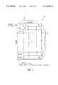
- FIG. 2is an interleaver for storing data in the transmitter of FIG. 1 .
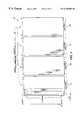
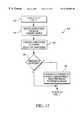
- FIG. 3is a flow diagram of the interleaving process.
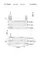
- FIG. 4is an illustration of four consecutive data copies read during the interleaving process of FIG. 3 .
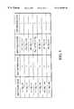
- FIG. 5is a table of soft decision conversion values produced by the demodulator of the receiver shown in FIG. 1 .
- FIG. 6is a schematic diagram of the controller for controlling the output of the deinterleaver of the receiver shown in FIG. 1 .
- FIG. 7is a process of de-interleaving and combining the copies produced by the interleaving process of FIG. 3 .
- FIG. 8 A and FIG. 8Bare illustrations of BPSK phase noise and QPSK phase noise computations, respectively, performed by the controller of FIG. 6 .
- FIG. 9is an illustration of the accumulation portion of phase noise averaging performed across both carriers and symbols shown in FIG. 7 .
- FIG. 10is an illustration of a weight table for determining the weighting to be applied to deinterleaver output copies based on the carrier and symbol phase noise average values.
- FIG. 11is an illustration of the bit metrics conversion performed by the controller of FIG. 6 .
- FIG. 12is the combining process (of FIG. 7) modified for jammer threshold detection.
- a data transmission system 10includes a transmitter 12 and a receiver 14 interconnected by a data transmission channel 16 .
- the transmitter 12includes an encoder 18 , an interleaver 20 and a modulator 22 .
- the receiver 14includes a demodulator 24 , a de-interleaver 26 , a decoder 28 and a controller 30 .
- datais presented to an input of the encoder 18 .
- the encoder 18encodes the data in a forward error correction code and writes the encoded data to the interleaver 20 . Any known forward error correction code, for example, a convolution code, can be used for this purpose.
- the modulator 22reads the encoded data from the interleaver 20 and modulates the encoded data onto carriers in OFDM symbols in accordance with conventional OFDM modulation techniques. Those modulation techniques may be coherent or differential. In the preferred embodiment, the modulation type may be either Binary Phase Shift Keying (BPSK) or Quadrature Phase Shift Keying (QPSK).
- BPSKBinary Phase Shift Keying
- QPSKQuadrature Phase Shift Keying
- the demodulator 24demodulates the OFDM symbols received from the transmission channel 16 and converts phase angles of the data in each carrier of each symbol to metric values.
- the phase angle to metric value conversion functionis indicated in the figure by reference numeral 31 .
- the demodulator 24stores the metric values in the deinterleaver 26 .
- the decoder 28reads the metric values from the deinterleaver 26 and uses the metric values for decoding purposes.
- the decoder 28corrects bit errors occurring during transmission from the encoder 18 to the decoder 28 .
- the decoder 28may include a Viterbi decoder and/or Reed-Solomon decoder.
- the error correction codeis such that bit errors which occur distributed uniformly throughout symbols and frequency carriers can be readily corrected. Burst errors, where a number of successive bits in successive symbols or adjacent frequencies are incorrect, can be less readily corrected.
- phase angle representationcould represent a phase angle in terms of a number of degrees from an expected value (e.g., 0 or 180 degrees).
- a received phase angle (A R ) having a value between 0 and 2 ⁇may be represented by a phase angle representation value of A R ⁇ ( ⁇ /2) if A R is less than or equal to ⁇ , or 2 ⁇ A R ⁇ ( ⁇ / 2) if A R is greater than ⁇ .
- phase angle informationas used herein will refer to either the metric values or the phase angle representation values.
- the controller 30is coupled to the receiver side of the transmission channel 16 , the de-interleaver 26 and the output of the de-interleaver 26 .
- the functionality of the controller 30will be described in detail later with reference to FIG. 6 .
- details of OFDM transmitter and receiver designwhich are known to those skilled in the art and not considered pertinent to the understanding of the transmission mode of the invention have been largely omitted herein.
- the interleaver 20is a row/column interleaver memory of M columns 32 and N rows 34 .
- Datais stored by row and read by column with some amount of shifting to reorder bits.
- the row numbers (addresses) Jare computed according to
- Kis the column number
- pis an offset parameter (indicating the amount by which the column bits are shifted)
- the interleaver 20is capable of being operated in two different modes: a standard transmission mode and a robust transmission mode.
- the interleaver 20stores 40 OFDM symbols to be transmitted in a single packet or block of data, and is addressed in the following manner.
- the encoder 18writes twenty bits of encoded data into consecutive rows starting at row 0 .
- the least significant bit (LSB) of the twenty bit wordis first-in-time encoded data.
- the LSB of the 20-bit wordwill be first-in-time modulated data.
- the above techniqueprovides data spreading in both time and frequency, allowing block errors in either domain to be spread far enough apart to allow correction by the decoder 28 .
- the interleaver 20uses ten columns (bits 0 to 9) instead of twenty. The number of rows is equal to the number of usable carriers per OFDM symbol. The interleaver 20 stores 10 OFDM symbols instead of 40 and is read four consecutive times to create a 40 symbol packet.
- an interleaver process 40 of robust modebegins by filling the interleaver 20 in the same manner as during standard transmission mode, that is, it stores the encoded data (FEC code words) by row (step 42 ).
- the modulator 22reads a first copy of the data from the interleaver 20 by columns, with each successive column read adding an offset of eight to the previous column's start row (step 44 ).
- the interleaver 20is read in its entirety four consecutive times. It starts with row 0 on the first pass.
- the second copyis read starting at a row number equal to (the number of usable carriers)*1 ⁇ 4 (step 46 ).
- the third copyis read starting at a row number equal to (the number of usable carriers)*1 ⁇ 2 (step 48 ).
- the starting row numberis equal to (the number of usable carriers)*3 ⁇ 4 (step 50 ).
- interleaver control circuitryfor controlling the mechanics of the reads and writes is well-known and therefore omitted from the description.
- Such control circuitrymay be included in the encoder 18 and modulator 22 , as is assumed in the illustrated embodiment, in the interleaver 20 itself, or may reside in a separate control unit.
- the four data copies 60include a first data copy 62 a, a second data copy 62 b , a third data copy 62 c and a fourth data copy 62 d .
- the first data copy 62 athe first read data bit corresponds to row 0 .
- the first read data bitcorresponds to row 21 .
- the third data copy 62 cwith the 1 ⁇ 2 row/address shift, the first read data bit corresponds to row number 42 .
- the first read data bitcorresponds to row number 63 , which reflects a shift equal to 3 ⁇ 4*(84 rows). It can be seen from the figure that the bit ordering in columns 1 through 9 of the first data copy is the result of the initial 8 bit shift. In the data copies 2 through 4 , the bit ordering in each column after the first column is the result of the 8 bit shift as well as the additional offset (1 ⁇ 4*84 for data copy 2 , 1 ⁇ 2*84 for data copy 3 and 3 ⁇ 4*84 for data copy 4 ).
- the above interleaving processensures that the data bit copies are not modulated onto adjacent carriers on a given symbol or neighboring symbols. Rather, they are spread uniformly in time and frequency so as to ensure successful decoding. While the redundant data need not be spread uniformly, it will be understood that the greater and more even the data copy spacing, the more robust the transmission is likely to be.
- the interleaver shift mechanismis adjustable for different numbers of usable carriers. If the number of usable carriers is 83, for instance, the 1 ⁇ 4 offset requires a 20 row shift instead of the 21 row shift used for all 84 carriers and the shift mechanism will be adjusted accordingly.
- the robust modehas a lower data rate than the standard transmission mode, its use may be limited to certain communications environments that require a high degree of reliability.
- the robust modemay be particularly well-suited for use in broadcast transmission modes, in which a sending node cannot adapt to each and every receiving node because each of those nodes has a different channel and those channels may have frequency nulls in different parts of the frequency band.
- Another usewould be to establish initial contact between nodes which communicate over a power line. During such an initial set-up, a sending node does not know which channel connects the sending node to the receiving node and thus will transmit in a mode that the receiver can hear.
- the sendermay not want to always transmit in the robust mode, as the robust mode may use too high a percentage of the channel.
- the sending node's goalis to migrate to the highest data rate as soon as possible so that other nodes can use the channel.
- the sending nodewon't know what that data rate is until it has established initial communications with the receiver.
- the encoder 18fills the interleaver 20 completely before the modulator 22 transmits any data over the transmission channel 16 to the receiver 14 .
- the demodulator 24demodulates the modulated carriers using a scheme appropriate to the modulation technique used by the modulator 22 .
- the phase angle to metric conversion function 31 of the demodulator 24produces from a phase angle for each bit of the transmitted carrier data a 3-bit soft decision value from 0 to 7 that represents a probability of a “0” or a “1” bit, with 7 representing a “1” and 0 representing a “0”.
- a phase differenceis determined using the following equation:
- D kis the k th carrier phase difference
- ⁇ kis the current symbol's k th carrier phase
- ⁇ kis the previous symbol's k th carrier phase
- 2 ⁇ radiansis the maximum phase value.
- D kis then offset by an amount, depending on the modulation type, to allow for a single soft decision conversion. Referring to the table shown in FIG. 5, the offset phase difference P k (for the k th carrier with a value 0-127) is mapped to a 3-bit soft decision value (also referred to as a “bit metric” value).
- the de-interleaver 26receives the 3-bit soft decision value for each data bit. All 3-bit soft decision values are de-interleaved (i.e., stored in the de-interleaver) as a group.
- the method for writing the interleaverapplies to reading the de-interleaver and the method of reading the interleaver applies to writing the de-interleaver.
- the write operationuses the reverse algorithm of that applied to the interleaver during a read operation.
- the controller 30includes a phase noise (PN) computation unit 70 , a phase noise memory 72 , which includes a carrier phase noise (PN c ) memory 72 a and a symbol phase noise (PN s ) memory 72 b , select logic including selectors 1 through 4 , corresponding to 74 a - 74 d , respectively, and weight lookup table logic including weight tables 1 through 4 , corresponding to 76 a - 76 d . Further included in the controller 30 are multipliers 78 a - 78 d , a summation unit 80 and a conversion unit 82 . Also included is decoding logic, including a decode unit 84 and a RAM address decoder 86 .
- phase noise computation unit 70monitors the phases of each carrier in each OFDM symbol as the OFDM symbol is received from the transmission channel 16 (step 92 ).
- the phase noise computation unit 70computes the phase noise associated with each carrier and each symbol (step 94 ) by performing i) phase noise estimation (step 96 ); ii) phase noise estimation accumulation and averaging (steps 98 and 100 ); and iii) threshold comparison/conversion (step 102 ).
- the phase noise estimation of step 96can be performed for either BPSK or QPSK, that is, whichever modulator type was used by the modulator.
- BPSKa binary 1 causes the transmission of a zero phase and binary 0 the transmission of a ⁇ phase.
- the phase noise computation unit 70measures how far the samples are from the expected 1 and 0 values.
- phase received from the modulatoris first converted to polar to give a corresponding phase angle sample.
- the constellation plot for the samplemay be represented in binary form, with 0 to 2 ⁇ radians being represented as 0 to 127 (or 0 to 255 ) points.
- the phase noise computation unit 70computes a phase noise estimation for the carrier frequency of that sample. It then computes an average of the computed phase noise values for each carrier frequency as well as each symbol. The average may be expressed as
- Y1
- and Ymod[X+( ⁇ /2); ⁇ ].
- Y1is the phase noise and is expressed in terms of number of points from the ideal expected modulation values, which in the case of BPSK are zero or ⁇ , the zero or ⁇ states being indicative of no noise.
- the phase angleis represented in binary form as a phase number between 0 and 127 (or 0 and 255).
- the phase noise computation unit 70creates a modulus of a phase number y, e.g. 64 (or 32 ), adds y/2 points, and finds X+(y/2) mod y. It then subtracts y/2 so that the result is always a value between ⁇ y/2 and +y/2. Once the phase noise computation unit 70 obtains the absolute value of that value, the result lies in the first quadrant (0 to y/2) of the constellation.
- FIG. 8 AAn exemplary phase noise calculation for BPSK is illustrated in FIG. 8 A.
- 2 ⁇ radiansis represented as a binary value corresponding to 128 points.
- the calculationadds 32 to give a sum of 112 and computes (112 mod 64).
- Yequals 48 and Y1 is equal to the absolute value of ( 48-32), or 16 points.
- phase noise computationmay be performed for QPSK, which uses four states (or phases) spaced ⁇ /2 apart.
- An exemplary QPSK phase noise estimationis illustrated in FIG. 8 B.
- the phase noise average of Eq. (3) and step 100 (of FIG. 7)may be computed for phase noise as a function of the carrier, the symbol, or both.
- the phase noise computation unit 70accumulates carrier values for a given carrier for all of the symbols and divides by the total number of symbols. In the described embodiment, the total number of symbols in an OFDM packet is 40.
- PN cis the average phase noise for a carrier for the entire block of data associated with the bit metrics stored in the deinterleaver.
- PN Sthe phase noise across all carriers in a symbol is accumulated and divided by total number of carriers (i.e., 84). The PN s .
- the combinationprovides an indication of how carrier phase noise varies (relative to PN c ) from symbol to symbol.
- the combinationprovides a reasonable estimate of signal-to-noise (S/N) for a given carrier on a symbol-by-symbol basis.
- phase noise values for each carrier 104are accumulated by summing the phase noise values for each carrier over the forty OFDM symbols 106 to give a sum, SUM(PNC(M)) 108 , where M is one of carriers 0 to 83.
- the phase noise valuesare accumulated for each OFDM symbol 106 by summing the phase noise values for all 84 carriers 104 to give a sum, SUM(PNS(N)) 110 , where N is one of symbols 1 through 40.
- the total number of symbol accumulations or sumsis therefore 40. Any carriers not used by the transmission are excluded from the summation.
- phase noise computation unit 70performs the phase noise average threshold comparison/conversion (step 102 ). That is, each carrier phase noise average PN c is compared to two thresholds, “C 1 ” and “C 2 ” to convert the PN c to one of 3 (2-bit) states or values: 0, 1 or 2. Each state indicates a different threshold level of sample quality. The zero value corresponds to “poor”, the one value to “medium”, and the two value to “good”.
- each PN sis compared to two thresholds “S 1 ” and “S 2 ” to convert the PN s to one of the same three values.
- the 2-bit values for PN s and PN cform a 4-bit select value which, under the control of the decode unit 84 , is provided by an appropriate selector of selectors 74 a-d to a corresponding one of the weight tables 76 a-d to select a weight value for the bit metric value (associated with one of the data bit copies) stored in the deinterleaver (step 112 ).
- the decode unit 84derives a carrier number and a symbol number for each bit number and bit copy number.
- the decode unit 84provides as a select to each of the selectors 74 a - 74 d the carrier number and the symbol number for the bit copy to which the selector corresponds. For example, if bit copy 1 was transmitted on carrier 1 of symbol 1 , then providing bit 1 and carrier 1 to the first selector 74 a serves to select the two-bit values for PN c for carrier 1 and PN c for symbol 1 as inputs to the first weight table 76 a .
- bit copy 2was transmitted on carrier 21 of symbol 11
- second selector 74 boperates to select the two-bit values for the PN c for carrier 21 and the PN s for symbol 11 as inputs to the second weight table 76 b . Selections are made in a similar fashion for bit copies 3 and 4 via their corresponding selectors 74 c and 74 d.
- the carrier and symbol numbers provided by the decode unit 84are also used by the RAM address decoder 86 in retrieving the appropriate bit metric values from the deinterleaver 26 .
- the weight selectionis further described with reference to the weight lookup table of FIG. 10 and Table 1 below.
- the four bit select valueis of the form: S 2 (bit 3 ), S 1 (bit 2 ), C 2 (bit 1 ) and C 1 (bit 0 ).
- the mapping of the select values, along their logical representations, to corresponding weightsis as follows:
- the weight table shown in FIG. 10is implemented in a is 5:1 multiplexer, with each of the 5 weight values as inputs and the selected weight (selected by the select value) as output.
- Each metric value copy read from the deinterleaver for each of the four copiesis multiplied by the corresponding weight value (provided by the corresponding one of weight tables 76 a - 76 d ) by a corresponding one of the multipliers 78 a - 78 d (step 114 ).
- the four weighted metric valuesare summed together by the summation unit 80 to produce a combined (or single) 10-bit metric value (step 116 ), which the conversion unit 82 converts to a “new” 3-bit metric value (step 118 ).
- the “new” metric valueis then processed by the decoder 28 .
- the above techniqueuses the phase noise computation to weight metric copies differently.
- the copy samples with less phase noiseare weighted more heavily than the copy samples with more phase noise.
- FIG. 11The complete transformation of the initial 3-bit values produced by the demodulator to the new 3-bit value as performed by the controller 30 is depicted in FIG. 11 .
- the 3-bit bit metric valuesare converted to 5-bit values as they are read out of the de-interleaver.
- the appropriate weightingis applied to the 5-bit value to produce an 8-bit weighted value.
- the four weighted valuesare summed together.
- the 10-bit sumis truncated and floored to give a 6-bit value.
- a +4 valueis added to the 6-bit value, which is then limited or saturated down to a 3-bit value ranging from 0 to 7.
- the bit metric valueis once again in a form which can be utilized by the Viterbi decoder.
- the controller 30 as described thus farmay be modified to include a jammer threshold detect unit 88 , which receives the amplitudes of the transmitted carrier samples of the four copies and can produce a separate override signal for each of the four copies (shown, collectively, as output signals 89 a through 89 d , which correspond to copies 1 - 4 , respectively) if the amplitude of that carrier sample copy exceeds a minimum jammer detection threshold level. If the minimum jammer detection threshold level is exceeded, the override signal overrides the weight selected by the above-described PN c /PN s select by forcing the output of the corresponding weight table for the copy to the minimum weight (“1 ⁇ 8”).
- a jammer threshold detect unit 88which receives the amplitudes of the transmitted carrier samples of the four copies and can produce a separate override signal for each of the four copies (shown, collectively, as output signals 89 a through 89 d , which correspond to copies 1 - 4 , respectively) if the amplitude
- a copy combine process(i.e., process of combining the metric values for the four transmitted copies into a single metric value) with jammer threshold detect 120 is shown in the flow diagram of FIG. 12 .
- the controller 30performs steps 92 through 112 from FIG. 7 (step 122 ).
- the controller 30also receives amplitudes of each carrier sample (step 124 ) and compares those amplitudes to a predetermined jammer detection threshold (step 126 ). If the predetermined jammer detection threshold is exceeded, the controller 30 generates an override signal for the copy to which the carrier sample corresponds to force the weight selected at step 112 (FIG. 7) to the minimum weight (step 130 ). If the threshold is not exceeded, the controller proceeds to step 114 from FIG.
- controller 7it provides the weight selected by PN c /PN s (at step 112 of FIG. 7) for each copy to the corresponding metric value copy as discussed above. If will be appreciated that the controller may perform steps 124 through 130 in parallel with the phase noise computations and related weight selections, as long as the override signal (if generated) is available to control the output of the corresponding weight table at the appropriate time.
- the phase noise computation unit 70could simply include a combining unit for summing the four values and using the sum to compute an average (i.e., straight, as opposed to weighted, averaging), or a selector (e.g., MUX) for selecting the best carrier from among the four values (copies).
- a combining unitfor summing the four values and using the sum to compute an average (i.e., straight, as opposed to weighted, averaging)
- a selectore.g., MUX
- phase noise computation unit 70could use the PN c and PN s values to estimate S/N for symbols and carriers, and use lookup tables based on the S/N estimates to arrive at new bit metric values which take into account how good or bad a particular carrier or symbol is.
- the demodulator 24could store phase angle representations for each of the copies in the deinterleaver instead of converting the copies to metric values and storing the metric value copies in the deinterleaver as described above.
- the phase angle-to-bit metric value conversion function(corresponding to the phase angle to metric value converter 31 of FIG. 1) would be performed at the output of the summation unit 80 (FIG. 6 ). That is, the phase angle to metric converter could be coupled to the summation unit 80 and conversion unit 82 so as to receive the combined weighted phase angle representation from the output of the summer 80 , and provide a metric value for that output to the input of the conversion unit 82 .
- phase angle-to-metric conversioncould be included in the converter unit 82 .
- the systemcould be implemented to include two separate converters—one in the demodulator and one at the output of the summation unit 80 —if also provided with suitable select/control logic, in order to support either deinterleaved metric value copies or phase angle representation value copies.
Landscapes
- Engineering & Computer Science (AREA)
- Signal Processing (AREA)
- Computer Networks & Wireless Communication (AREA)
- Physics & Mathematics (AREA)
- Probability & Statistics with Applications (AREA)
- Theoretical Computer Science (AREA)
- Error Detection And Correction (AREA)
- Digital Transmission Methods That Use Modulated Carrier Waves (AREA)
- Detection And Prevention Of Errors In Transmission (AREA)
- Radio Transmission System (AREA)
- Surface Acoustic Wave Elements And Circuit Networks Thereof (AREA)
Abstract
Description
| TABLE 1 | ||
| Select | Logic Expression | Weight |
| 1X1X | S2C2 | 1 |
| 1X01 | S2C2,C1 | {fraction ( 3/4)} |
| 1X00 | S2C2,C1′ | {fraction ( 1/2)} |
| 011X | S2′S1C2 | {fraction ( 3/4)} |
| 0101 | S2′S1C2′C1 | {fraction ( 1/2)} |
| 0100 | S2′S1C2′C1′ | {fraction ( 1/4)} |
| 001X | S2′S1′C2 | {fraction ( i/2)} |
| 0001 | S2′S1′C2′C1 | {fraction ( 1/4)} |
| 0000 | S2′S1′C2′C1′ | {fraction ( 1/8)} |
Claims (19)
Priority Applications (14)
| Application Number | Priority Date | Filing Date | Title |
|---|---|---|---|
| US09/377,131US6278685B1 (en) | 1999-08-19 | 1999-08-19 | Robust transmission mode |
| PCT/US2000/022911WO2001013560A1 (en) | 1999-08-19 | 2000-08-21 | Robust transmission mode |
| MXPA01013418AMXPA01013418A (en) | 1999-08-19 | 2000-08-21 | Robust transmission mode. |
| JP2001517738AJP4429562B2 (en) | 1999-08-19 | 2000-08-21 | Robust transmission mode |
| CNB00805522XACN100386979C (en) | 1999-08-19 | 2000-08-21 | Robust Transport Mode |
| AU70637/00AAU768374B2 (en) | 1999-08-19 | 2000-08-21 | Robust transmission mode |
| BRPI0009118ABRPI0009118B1 (en) | 1999-08-19 | 2000-08-21 | robust transmission mode |
| DE60045378TDE60045378D1 (en) | 1999-08-19 | 2000-08-21 | ROBUST TRANSMISSION MODE |
| AT00959290TATE492079T1 (en) | 1999-08-19 | 2000-08-21 | ROBUST TRANSMISSION MODE |
| KR1020087002356AKR100876625B1 (en) | 1999-08-19 | 2000-08-21 | Robust transmission mode |
| KR1020017011707AKR100840631B1 (en) | 1999-08-19 | 2000-08-21 | Robust transmission mode |
| EP00959290AEP1203467B1 (en) | 1999-08-19 | 2000-08-21 | Robust transmission mode |
| CN2007101399432ACN101159728B (en) | 1999-08-19 | 2000-08-21 | Robust transmission mode |
| CA2366662ACA2366662C (en) | 1999-08-19 | 2000-08-21 | Robust transmission mode |
Applications Claiming Priority (1)
| Application Number | Priority Date | Filing Date | Title |
|---|---|---|---|
| US09/377,131US6278685B1 (en) | 1999-08-19 | 1999-08-19 | Robust transmission mode |
Publications (1)
| Publication Number | Publication Date |
|---|---|
| US6278685B1true US6278685B1 (en) | 2001-08-21 |
Family
ID=23487897
Family Applications (1)
| Application Number | Title | Priority Date | Filing Date |
|---|---|---|---|
| US09/377,131Expired - LifetimeUS6278685B1 (en) | 1999-08-19 | 1999-08-19 | Robust transmission mode |
Country Status (12)
| Country | Link |
|---|---|
| US (1) | US6278685B1 (en) |
| EP (1) | EP1203467B1 (en) |
| JP (1) | JP4429562B2 (en) |
| KR (2) | KR100876625B1 (en) |
| CN (2) | CN101159728B (en) |
| AT (1) | ATE492079T1 (en) |
| AU (1) | AU768374B2 (en) |
| BR (1) | BRPI0009118B1 (en) |
| CA (1) | CA2366662C (en) |
| DE (1) | DE60045378D1 (en) |
| MX (1) | MXPA01013418A (en) |
| WO (1) | WO2001013560A1 (en) |
Cited By (50)
| Publication number | Priority date | Publication date | Assignee | Title |
|---|---|---|---|---|
| US20020075841A1 (en)* | 2000-12-19 | 2002-06-20 | Steer David G. | Enhanced ARQ with OFDM modulation symbols |
| US20020194570A1 (en)* | 2001-04-02 | 2002-12-19 | Koninklijke Philips Electronics N.V.; | Improved digital transmission system for an enhanced ATSC 8-VSB system |
| US6522626B1 (en)* | 1998-12-15 | 2003-02-18 | Nortel Networks Limited | Power line communications system and method of operation thereof |
| US20030051206A1 (en)* | 2000-03-02 | 2003-03-13 | Hisashi Kondo | Decoder |
| US6601213B1 (en)* | 1999-06-15 | 2003-07-29 | Mitsubishi Denki Kabushiki Kaisha | Demodulator and communications system |
| US20030181185A1 (en)* | 2002-02-28 | 2003-09-25 | Itay Lusky | Noise identification in a communication system |
| US6671284B1 (en)* | 2000-08-04 | 2003-12-30 | Intellon Corporation | Frame control for efficient media access |
| US20040218695A1 (en)* | 2003-02-19 | 2004-11-04 | Matsushita Electric Industrial Co., Ltd. | Receiving apparatus and method for digital multi-carrier transmission |
| US6909723B1 (en) | 2000-08-04 | 2005-06-21 | Intellon Corporation | Segment bursting with priority pre-emption and reduced latency |
| US20050271158A1 (en)* | 2002-11-04 | 2005-12-08 | Koninklijke Philips Electronics N.V. | Configuration for implementing enhanced vsb on the studio side |
| US20060036924A1 (en)* | 2004-08-16 | 2006-02-16 | Monisha Ghosh | Interleaving and parsing for MIMO-OFDM systems |
| US20060062193A1 (en)* | 2004-09-16 | 2006-03-23 | Infineon Technologies Ag | Medium access control unit |
| US20060164973A1 (en)* | 2005-01-27 | 2006-07-27 | Samsung Electronics Co., Ltd. | Interleaving method in OFDM system |
| US7120847B2 (en) | 2002-06-26 | 2006-10-10 | Intellon Corporation | Powerline network flood control restriction |
| US7170849B1 (en)* | 2001-03-19 | 2007-01-30 | Cisco Systems Wireless Networking (Australia) Pty Limited | Interleaver, deinterleaver, interleaving method, and deinterleaving method for OFDM data |
| US20070025398A1 (en)* | 2005-07-27 | 2007-02-01 | Yonge Lawrence W Iii | Time synchronization in a network |
| US20070112972A1 (en)* | 2003-11-24 | 2007-05-17 | Yonge Lawrence W Iii | Encrypting data in a communication network |
| US7281187B2 (en) | 2003-11-20 | 2007-10-09 | Intellon Corporation | Using error checking bits to communicated an address or other bits |
| US7352770B1 (en) | 2000-08-04 | 2008-04-01 | Intellon Corporation | Media access control protocol with priority and contention-free intervals |
| US20080153430A1 (en)* | 2006-12-21 | 2008-06-26 | Intellon Corporation | Selecting carriers for modulating signals in a communication network |
| US20080165969A1 (en)* | 2007-01-05 | 2008-07-10 | Qualcomm Incorporated | Pilot transmission in a wireless communication system |
| US20080166969A1 (en)* | 2007-01-04 | 2008-07-10 | Qualcomm Incorporated | Method and apparatus for utilizing other sector interference (osi) indication |
| US20080167040A1 (en)* | 2007-01-04 | 2008-07-10 | Qualcomm Incorporated | Control resource mapping for a wireless communication system |
| US20080240159A1 (en)* | 2007-01-05 | 2008-10-02 | Qualcomm Incorporated | Mapping of subpackets to resources in a communication system |
| US20080301446A1 (en)* | 2007-06-04 | 2008-12-04 | Intellon Corporation | Authorizing customer premise equipment into a network |
| WO2008147053A1 (en)* | 2007-06-01 | 2008-12-04 | Samsung Electronics Co., Ltd. | Orthogonal frequency-division multiplexing (ofdm) transmitting and receiving device for transmismitting and receiving an ofdm symbol having symbols interleaved variably, and methods thereof |
| US20090274035A1 (en)* | 2005-12-07 | 2009-11-05 | Isabelle Siaud | Dynamic Interleaving Method and Device |
| US7623542B2 (en) | 2002-10-21 | 2009-11-24 | Intellon Corporation | Contention-free access intervals on a CSMA network |
| US7636370B2 (en) | 2005-03-03 | 2009-12-22 | Intellon Corporation | Reserving time periods for communication on power line networks |
| US20100008214A1 (en)* | 2004-12-31 | 2010-01-14 | Isabelle Siaud | Interleaving with iterative calculation of interleaving addresses |
| US7660327B2 (en) | 2004-02-03 | 2010-02-09 | Atheros Communications, Inc. | Temporary priority promotion for network communications in which access to a shared medium depends on a priority level |
| US20100111099A1 (en)* | 2005-07-27 | 2010-05-06 | Intellon Corporation, Sharp Corporation, Coppergate Communications Ltd. | Communicating in a network that includes a medium having varying transmission characteristics |
| US7715425B2 (en) | 2004-02-26 | 2010-05-11 | Atheros Communications, Inc. | Channel adaptation synchronized to periodically varying channel |
| US7822059B2 (en) | 2005-07-27 | 2010-10-26 | Atheros Communications, Inc. | Managing contention-free time allocations in a network |
| US7826466B2 (en) | 2002-06-26 | 2010-11-02 | Atheros Communications, Inc. | Communication buffer scheme optimized for VoIP, QoS and data networking over a power line |
| US20110164514A1 (en)* | 2010-01-04 | 2011-07-07 | Atheros Communications, Inc. | Transmit Power Control |
| US20110280261A1 (en)* | 2010-05-11 | 2011-11-17 | Texas Instruments Incorporated | Interleaver Design and Header Structure For ITU G.hnem |
| US8090857B2 (en) | 2003-11-24 | 2012-01-03 | Qualcomm Atheros, Inc. | Medium access control layer that encapsulates data from a plurality of received data units into a plurality of independently transmittable blocks |
| US8149703B2 (en) | 2002-06-26 | 2012-04-03 | Qualcomm Atheros, Inc. | Powerline network bridging congestion control |
| US8175190B2 (en) | 2005-07-27 | 2012-05-08 | Qualcomm Atheros, Inc. | Managing spectra of modulated signals in a communication network |
| WO2012071263A1 (en) | 2010-11-22 | 2012-05-31 | Qualcomm Atheros, Inc. | Path characteristic based association of communication devices |
| US20120257448A1 (en)* | 2011-04-11 | 2012-10-11 | Grandis, Inc. | Multi-Cell Per Memory-Bit Circuit and Method |
| US8493995B2 (en) | 2007-05-10 | 2013-07-23 | Qualcomm Incorporated | Managing distributed access to a shared medium |
| US8614961B1 (en)* | 2008-12-31 | 2013-12-24 | Qualcomm Incorporated | Efficient communication over a shared medium |
| US8660013B2 (en) | 2010-04-12 | 2014-02-25 | Qualcomm Incorporated | Detecting delimiters for low-overhead communication in a network |
| US8891605B2 (en) | 2013-03-13 | 2014-11-18 | Qualcomm Incorporated | Variable line cycle adaptation for powerline communications |
| US8929393B2 (en) | 2010-05-03 | 2015-01-06 | Qualcomm Incorporated | Method and apparatus for communication with shortened signal formats |
| US9667318B2 (en) | 2010-05-11 | 2017-05-30 | Texas Instruments Corporation | Device and frame structure for powerline communications |
| US9949276B2 (en) | 2008-03-28 | 2018-04-17 | Qualcomm Incorporated | Signaling message transmission in a wireless communication network |
| US20240097962A1 (en)* | 2022-09-15 | 2024-03-21 | Nordic Semiconductor Asa | Signal processing |
Families Citing this family (16)
| Publication number | Priority date | Publication date | Assignee | Title |
|---|---|---|---|---|
| DE10127346C2 (en)* | 2001-06-06 | 2003-07-17 | Siemens Ag | Multi-carrier data transmission system and method for suppressing interference in a multi-carrier data transmission system |
| WO2004015948A1 (en)* | 2002-08-13 | 2004-02-19 | Nokia Corporation | Symbol interleaving |
| CN100544239C (en)* | 2003-02-14 | 2009-09-23 | 华为技术有限公司 | Interleaving Method for Orthogonal Frequency Division Multiplexing Communication |
| CN101677309B (en)* | 2003-02-14 | 2013-11-06 | 华为技术有限公司 | Launcher, interleaver and interleaving method |
| US7418042B2 (en)* | 2003-09-17 | 2008-08-26 | Atheros Communications, Inc. | Repetition coding for a wireless system |
| JP4671803B2 (en)* | 2005-08-15 | 2011-04-20 | シャープ株式会社 | Downlink control information mapping method, receiving method, base station apparatus, mobile station apparatus, program for executing these, and recording medium |
| US8149967B2 (en) | 2008-06-06 | 2012-04-03 | Maxim Integrated Products, Inc. | Combined dual feed-forward and feedback analog and digital automatic gain control for broadband communication |
| US8139614B2 (en)* | 2008-06-06 | 2012-03-20 | Maxim Integrated Products, Inc. | Robust narrowband symbol and frame synchronizer for power-line communication |
| US8165172B2 (en) | 2008-06-06 | 2012-04-24 | Maxim Integrated Products, Inc. | Robust wideband symbol and frame synchronizer for power-line communication |
| US8284825B2 (en) | 2008-06-06 | 2012-10-09 | Maxim Integrated Products, Inc. | Blind channel quality estimator |
| US8472576B2 (en) | 2008-06-06 | 2013-06-25 | Maxim Integrated Products, Inc. | Jammer canceller for power-line communication |
| US8315152B2 (en)* | 2008-06-06 | 2012-11-20 | Maxim Integrated Products, Inc. | System and method for applying multi-tone OFDM based communications within a prescribed frequency range |
| US8276025B2 (en) | 2008-06-06 | 2012-09-25 | Maxim Integrated Products, Inc. | Block interleaving scheme with configurable size to achieve time and frequency diversity |
| US8315341B2 (en) | 2008-06-06 | 2012-11-20 | Maxim Integrated Products, Inc. | Soft repetition code combiner using channel state information |
| US8320233B2 (en) | 2009-06-12 | 2012-11-27 | Maxim Integrated Products, Inc. | Transmitter and method for applying multi-tone OFDM based communications within a lower frequency range |
| CN112543088A (en)* | 2020-12-04 | 2021-03-23 | 青岛鼎信通讯股份有限公司 | Data diversity copying method suitable for medium-voltage power line broadband communication |
Citations (23)
| Publication number | Priority date | Publication date | Assignee | Title |
|---|---|---|---|---|
| US4881241A (en) | 1988-02-24 | 1989-11-14 | Centre National D'etudes Des Telecommunications | Method and installation for digital communication, particularly between and toward moving vehicles |
| US5197061A (en) | 1990-03-23 | 1993-03-23 | Etat Francais | Device for the transmission of digital data with at least two levels of protection and corresponding reception device |
| US5228025A (en) | 1990-02-06 | 1993-07-13 | Centre National D'etudes Des Telecommunications | Method for the broadcasting of digital data, notably for radio broadcasting at a high bit-rate towards mobile receivers, with time-frequency interlacing and assistance in the acquisition of automatic frequency control, and corresponding receiver |
| US5274629A (en) | 1990-02-06 | 1993-12-28 | Etat Francais and Telediffusion de France SA | Method for the broadcasting of digital data, notably for radio broadcasting at high bit rate towards mobile receivers, with time-frequency interlacing and coherent demodulation |
| US5307376A (en) | 1991-01-17 | 1994-04-26 | France Telecom | Device for the coherent demodulation of time-frequency interlaced digital data, with estimation of the frequency response of the transmission channel and threshold, and corresponsing transmitter |
| US5416801A (en) | 1992-07-08 | 1995-05-16 | U.S. Philips Corporation | Digital signal transmission system based on partitioning of a coded modulation with concatenated codings |
| US5452322A (en) | 1993-03-17 | 1995-09-19 | U.S. Philips Corporation | Receiver for digital signals transmitted in the coded differential modulation mode |
| US5452288A (en) | 1992-04-08 | 1995-09-19 | France Telecom | Method for the transmission of digital data in radio paging systems and corresponding radio paging receiver |
| US5483529A (en) | 1993-02-08 | 1996-01-09 | U.S. Philips Corporation | Receiver |
| US5488632A (en) | 1990-03-30 | 1996-01-30 | National Transcommunications Limited | Transmission and reception in a hostile interference environment |
| US5524027A (en) | 1994-04-22 | 1996-06-04 | U. S. Philips Corporation | Data receiver, method of calculating metrics, and signal processing device |
| US5610908A (en) | 1992-09-07 | 1997-03-11 | British Broadcasting Corporation | Digital signal transmission system using frequency division multiplex |
| US5694389A (en) | 1995-02-24 | 1997-12-02 | Kabushiki Kaisha Toshiba | OFDM transmission/reception system and transmitting/receiving apparatus |
| US5732113A (en)* | 1996-06-20 | 1998-03-24 | Stanford University | Timing and frequency synchronization of OFDM signals |
| US5757766A (en) | 1995-05-31 | 1998-05-26 | Sony Corporation | Transmitter and receiver for orthogonal frequency division multiplexing signal |
| US5799033A (en) | 1995-02-01 | 1998-08-25 | U.S. Philips Corporation | Method of error protected transmission, method of error protected reception of data and transmission system for transmission of data |
| US5812599A (en) | 1995-07-11 | 1998-09-22 | Alcatel N.V. | Method for allocating data elements in multicarrier applications and equipment to perform this method |
| US5903614A (en) | 1996-12-26 | 1999-05-11 | Sony Corporation | Communication method and receiving apparatus |
| US5914932A (en) | 1996-12-26 | 1999-06-22 | Sony Corporation | Communication method and receiving apparatus |
| US5966412A (en) | 1997-06-30 | 1999-10-12 | Thomson Consumer Electronics, Inc. | Apparatus and method for processing a Quadrature Amplitude Modulated (QAM) signal |
| US6125150A (en)* | 1995-10-30 | 2000-09-26 | The Board Of Trustees Of The Leland Stanford, Junior University | Transmission system using code designed for transmission with periodic interleaving |
| US6151296A (en) | 1997-06-19 | 2000-11-21 | Qualcomm Incorporated | Bit interleaving for orthogonal frequency division multiplexing in the transmission of digital signals |
| US6192068B1 (en)* | 1996-10-03 | 2001-02-20 | Wi-Lan Inc. | Multicode spread spectrum communications system |
Family Cites Families (9)
| Publication number | Priority date | Publication date | Assignee | Title |
|---|---|---|---|---|
| WO1985003180A1 (en)* | 1984-01-11 | 1985-07-18 | Telebit Corporation | Packetized ensemble modem |
| US5283780A (en)* | 1990-10-18 | 1994-02-01 | Stanford Telecommunications, Inc. | Digital audio broadcasting system |
| US5912917A (en)* | 1990-10-18 | 1999-06-15 | Engelbrecht; Lloyd | Digital broadcast system |
| US5301209A (en)* | 1991-10-09 | 1994-04-05 | At&T Bell Laboratories | Multidimensional trellis-coded modulation for fading channels |
| EP0759665B1 (en)* | 1995-08-21 | 2002-07-24 | Alcatel | Method for interleaving data frames, forward error correcting device and modulator including such a device |
| KR100498752B1 (en)* | 1996-09-02 | 2005-11-08 | 소니 가부시끼 가이샤 | Apparatus and method for receiving data using bit metrics |
| EP0854619A1 (en)* | 1997-01-15 | 1998-07-22 | Alcatel | Method to allocate data bits, multicarrier transmitter and receiver using the method, and related allocation message generator |
| GB9715396D0 (en)* | 1997-07-23 | 1997-09-24 | Philips Electronics Nv | Radio communication system |
| IL121450A0 (en)* | 1997-08-01 | 1998-02-08 | Smollett Neil | Ophthalmic surgical equipment |
- 1999
- 1999-08-19USUS09/377,131patent/US6278685B1/ennot_activeExpired - Lifetime
- 2000
- 2000-08-21CACA2366662Apatent/CA2366662C/ennot_activeExpired - Fee Related
- 2000-08-21CNCN2007101399432Apatent/CN101159728B/ennot_activeExpired - Fee Related
- 2000-08-21ATAT00959290Tpatent/ATE492079T1/ennot_activeIP Right Cessation
- 2000-08-21MXMXPA01013418Apatent/MXPA01013418A/enactiveIP Right Grant
- 2000-08-21DEDE60045378Tpatent/DE60045378D1/ennot_activeExpired - Lifetime
- 2000-08-21BRBRPI0009118Apatent/BRPI0009118B1/ennot_activeIP Right Cessation
- 2000-08-21JPJP2001517738Apatent/JP4429562B2/ennot_activeExpired - Fee Related
- 2000-08-21CNCNB00805522XApatent/CN100386979C/ennot_activeExpired - Fee Related
- 2000-08-21AUAU70637/00Apatent/AU768374B2/ennot_activeCeased
- 2000-08-21EPEP00959290Apatent/EP1203467B1/ennot_activeExpired - Lifetime
- 2000-08-21KRKR1020087002356Apatent/KR100876625B1/ennot_activeExpired - Fee Related
- 2000-08-21KRKR1020017011707Apatent/KR100840631B1/ennot_activeExpired - Fee Related
- 2000-08-21WOPCT/US2000/022911patent/WO2001013560A1/enactiveApplication Filing
Patent Citations (23)
| Publication number | Priority date | Publication date | Assignee | Title |
|---|---|---|---|---|
| US4881241A (en) | 1988-02-24 | 1989-11-14 | Centre National D'etudes Des Telecommunications | Method and installation for digital communication, particularly between and toward moving vehicles |
| US5228025A (en) | 1990-02-06 | 1993-07-13 | Centre National D'etudes Des Telecommunications | Method for the broadcasting of digital data, notably for radio broadcasting at a high bit-rate towards mobile receivers, with time-frequency interlacing and assistance in the acquisition of automatic frequency control, and corresponding receiver |
| US5274629A (en) | 1990-02-06 | 1993-12-28 | Etat Francais and Telediffusion de France SA | Method for the broadcasting of digital data, notably for radio broadcasting at high bit rate towards mobile receivers, with time-frequency interlacing and coherent demodulation |
| US5197061A (en) | 1990-03-23 | 1993-03-23 | Etat Francais | Device for the transmission of digital data with at least two levels of protection and corresponding reception device |
| US5488632A (en) | 1990-03-30 | 1996-01-30 | National Transcommunications Limited | Transmission and reception in a hostile interference environment |
| US5307376A (en) | 1991-01-17 | 1994-04-26 | France Telecom | Device for the coherent demodulation of time-frequency interlaced digital data, with estimation of the frequency response of the transmission channel and threshold, and corresponsing transmitter |
| US5452288A (en) | 1992-04-08 | 1995-09-19 | France Telecom | Method for the transmission of digital data in radio paging systems and corresponding radio paging receiver |
| US5416801A (en) | 1992-07-08 | 1995-05-16 | U.S. Philips Corporation | Digital signal transmission system based on partitioning of a coded modulation with concatenated codings |
| US5610908A (en) | 1992-09-07 | 1997-03-11 | British Broadcasting Corporation | Digital signal transmission system using frequency division multiplex |
| US5483529A (en) | 1993-02-08 | 1996-01-09 | U.S. Philips Corporation | Receiver |
| US5452322A (en) | 1993-03-17 | 1995-09-19 | U.S. Philips Corporation | Receiver for digital signals transmitted in the coded differential modulation mode |
| US5524027A (en) | 1994-04-22 | 1996-06-04 | U. S. Philips Corporation | Data receiver, method of calculating metrics, and signal processing device |
| US5799033A (en) | 1995-02-01 | 1998-08-25 | U.S. Philips Corporation | Method of error protected transmission, method of error protected reception of data and transmission system for transmission of data |
| US5694389A (en) | 1995-02-24 | 1997-12-02 | Kabushiki Kaisha Toshiba | OFDM transmission/reception system and transmitting/receiving apparatus |
| US5757766A (en) | 1995-05-31 | 1998-05-26 | Sony Corporation | Transmitter and receiver for orthogonal frequency division multiplexing signal |
| US5812599A (en) | 1995-07-11 | 1998-09-22 | Alcatel N.V. | Method for allocating data elements in multicarrier applications and equipment to perform this method |
| US6125150A (en)* | 1995-10-30 | 2000-09-26 | The Board Of Trustees Of The Leland Stanford, Junior University | Transmission system using code designed for transmission with periodic interleaving |
| US5732113A (en)* | 1996-06-20 | 1998-03-24 | Stanford University | Timing and frequency synchronization of OFDM signals |
| US6192068B1 (en)* | 1996-10-03 | 2001-02-20 | Wi-Lan Inc. | Multicode spread spectrum communications system |
| US5903614A (en) | 1996-12-26 | 1999-05-11 | Sony Corporation | Communication method and receiving apparatus |
| US5914932A (en) | 1996-12-26 | 1999-06-22 | Sony Corporation | Communication method and receiving apparatus |
| US6151296A (en) | 1997-06-19 | 2000-11-21 | Qualcomm Incorporated | Bit interleaving for orthogonal frequency division multiplexing in the transmission of digital signals |
| US5966412A (en) | 1997-06-30 | 1999-10-12 | Thomson Consumer Electronics, Inc. | Apparatus and method for processing a Quadrature Amplitude Modulated (QAM) signal |
Cited By (115)
| Publication number | Priority date | Publication date | Assignee | Title |
|---|---|---|---|---|
| US6522626B1 (en)* | 1998-12-15 | 2003-02-18 | Nortel Networks Limited | Power line communications system and method of operation thereof |
| US6601213B1 (en)* | 1999-06-15 | 2003-07-29 | Mitsubishi Denki Kabushiki Kaisha | Demodulator and communications system |
| US7080307B2 (en)* | 2000-03-02 | 2006-07-18 | Kawasaki Steel Corporation | Error correction decoder with correction of lowest soft decisions |
| US20030051206A1 (en)* | 2000-03-02 | 2003-03-13 | Hisashi Kondo | Decoder |
| US6671284B1 (en)* | 2000-08-04 | 2003-12-30 | Intellon Corporation | Frame control for efficient media access |
| US7916746B2 (en) | 2000-08-04 | 2011-03-29 | Atheros Communications, Inc. | Media access control protocol with priority and contention-free intervals |
| US6909723B1 (en) | 2000-08-04 | 2005-06-21 | Intellon Corporation | Segment bursting with priority pre-emption and reduced latency |
| US7352770B1 (en) | 2000-08-04 | 2008-04-01 | Intellon Corporation | Media access control protocol with priority and contention-free intervals |
| US20020075841A1 (en)* | 2000-12-19 | 2002-06-20 | Steer David G. | Enhanced ARQ with OFDM modulation symbols |
| US7110351B2 (en)* | 2000-12-19 | 2006-09-19 | Nortel Networks Limited | Enhanced ARQ with OFDM modulation symbols |
| US7430215B2 (en) | 2001-03-19 | 2008-09-30 | Cisco Technology, Inc. | Interleaver, deinterleaver, interleaving method, and deinterleaving method for OFDM data |
| US20070043982A1 (en)* | 2001-03-19 | 2007-02-22 | Thangadurai Arivoli | Interleaver, deinterleaver, interleaving method, and deinterleaving method for ofdm data |
| US7170849B1 (en)* | 2001-03-19 | 2007-01-30 | Cisco Systems Wireless Networking (Australia) Pty Limited | Interleaver, deinterleaver, interleaving method, and deinterleaving method for OFDM data |
| US7111221B2 (en) | 2001-04-02 | 2006-09-19 | Koninklijke Philips Electronics N.V. | Digital transmission system for an enhanced ATSC 8-VSB system |
| US20020194570A1 (en)* | 2001-04-02 | 2002-12-19 | Koninklijke Philips Electronics N.V.; | Improved digital transmission system for an enhanced ATSC 8-VSB system |
| US20030181185A1 (en)* | 2002-02-28 | 2003-09-25 | Itay Lusky | Noise identification in a communication system |
| US7152025B2 (en)* | 2002-02-28 | 2006-12-19 | Texas Instruments Incorporated | Noise identification in a communication system |
| US8149703B2 (en) | 2002-06-26 | 2012-04-03 | Qualcomm Atheros, Inc. | Powerline network bridging congestion control |
| US7120847B2 (en) | 2002-06-26 | 2006-10-10 | Intellon Corporation | Powerline network flood control restriction |
| US7826466B2 (en) | 2002-06-26 | 2010-11-02 | Atheros Communications, Inc. | Communication buffer scheme optimized for VoIP, QoS and data networking over a power line |
| US7623542B2 (en) | 2002-10-21 | 2009-11-24 | Intellon Corporation | Contention-free access intervals on a CSMA network |
| US7944988B2 (en)* | 2002-11-04 | 2011-05-17 | Koninklijke Philips Electronics N.V. | Configuration for implementing enhanced VSB on the studio side |
| US20050271158A1 (en)* | 2002-11-04 | 2005-12-08 | Koninklijke Philips Electronics N.V. | Configuration for implementing enhanced vsb on the studio side |
| US20040218695A1 (en)* | 2003-02-19 | 2004-11-04 | Matsushita Electric Industrial Co., Ltd. | Receiving apparatus and method for digital multi-carrier transmission |
| US6944232B2 (en) | 2003-02-19 | 2005-09-13 | Matsushita Electric Industrial Co. Ltd. | Receiving apparatus and method for digital multi-carrier transmission |
| US7281187B2 (en) | 2003-11-20 | 2007-10-09 | Intellon Corporation | Using error checking bits to communicated an address or other bits |
| US20070112972A1 (en)* | 2003-11-24 | 2007-05-17 | Yonge Lawrence W Iii | Encrypting data in a communication network |
| US9013989B2 (en) | 2003-11-24 | 2015-04-21 | Qualcomm Incorporated | Medium access control layer that encapsulates data from a plurality of received data units into a plurality of independently transmittable blocks |
| US8654635B2 (en) | 2003-11-24 | 2014-02-18 | Qualcomm Incorporated | Medium access control layer that encapsulates data from a plurality of received data units into a plurality of independently transmittable blocks |
| US8090857B2 (en) | 2003-11-24 | 2012-01-03 | Qualcomm Atheros, Inc. | Medium access control layer that encapsulates data from a plurality of received data units into a plurality of independently transmittable blocks |
| US7684568B2 (en) | 2003-11-24 | 2010-03-23 | Intellon Corporation | Encrypting data in a communication network |
| US7660327B2 (en) | 2004-02-03 | 2010-02-09 | Atheros Communications, Inc. | Temporary priority promotion for network communications in which access to a shared medium depends on a priority level |
| US7715425B2 (en) | 2004-02-26 | 2010-05-11 | Atheros Communications, Inc. | Channel adaptation synchronized to periodically varying channel |
| US20060036924A1 (en)* | 2004-08-16 | 2006-02-16 | Monisha Ghosh | Interleaving and parsing for MIMO-OFDM systems |
| US8527855B2 (en)* | 2004-08-16 | 2013-09-03 | Koninklijke Philips N.V. | Interleaving and parsing for MIMO-OFDM systems |
| US20060062193A1 (en)* | 2004-09-16 | 2006-03-23 | Infineon Technologies Ag | Medium access control unit |
| US8194527B2 (en)* | 2004-12-31 | 2012-06-05 | France Telecom | Interleaving with iterative calculation of interleaving addresses |
| US20100008214A1 (en)* | 2004-12-31 | 2010-01-14 | Isabelle Siaud | Interleaving with iterative calculation of interleaving addresses |
| US7797617B2 (en)* | 2005-01-27 | 2010-09-14 | Samsung Electronics Co., Ltd. | Interleaving method in OFDM system |
| US20060164973A1 (en)* | 2005-01-27 | 2006-07-27 | Samsung Electronics Co., Ltd. | Interleaving method in OFDM system |
| US7636370B2 (en) | 2005-03-03 | 2009-12-22 | Intellon Corporation | Reserving time periods for communication on power line networks |
| EP2611040A2 (en) | 2005-07-27 | 2013-07-03 | Qualcomm Atheros, Inc. | Managing spectra of modulated signals in a communication network |
| US8416887B2 (en) | 2005-07-27 | 2013-04-09 | Qualcomm Atheros, Inc | Managing spectra of modulated signals in a communication network |
| US20100111099A1 (en)* | 2005-07-27 | 2010-05-06 | Intellon Corporation, Sharp Corporation, Coppergate Communications Ltd. | Communicating in a network that includes a medium having varying transmission characteristics |
| US8089901B2 (en) | 2005-07-27 | 2012-01-03 | Qualcomm Atheros, Inc. | Communicating in a network that includes a medium having varying transmission characteristics |
| US7729372B2 (en) | 2005-07-27 | 2010-06-01 | Sharp Corporation | Communicating in a network that includes a medium having varying transmission characteristics |
| US20090207865A1 (en)* | 2005-07-27 | 2009-08-20 | Intellon Corporation | Time synchronization in a network |
| US7822059B2 (en) | 2005-07-27 | 2010-10-26 | Atheros Communications, Inc. | Managing contention-free time allocations in a network |
| US7558294B2 (en) | 2005-07-27 | 2009-07-07 | Intellon Corporation | Time synchronization in a network |
| US7894487B2 (en) | 2005-07-27 | 2011-02-22 | Sharp Corporation | Time synchronization in a network |
| US8175190B2 (en) | 2005-07-27 | 2012-05-08 | Qualcomm Atheros, Inc. | Managing spectra of modulated signals in a communication network |
| US20070025398A1 (en)* | 2005-07-27 | 2007-02-01 | Yonge Lawrence W Iii | Time synchronization in a network |
| US8462612B2 (en)* | 2005-12-07 | 2013-06-11 | France Telecom | Dynamic interleaving method and device |
| US20090274035A1 (en)* | 2005-12-07 | 2009-11-05 | Isabelle Siaud | Dynamic Interleaving Method and Device |
| US7904021B2 (en) | 2006-12-21 | 2011-03-08 | Atheros Communications, Inc. | Selecting carriers for modulating signals in a communication network |
| US20080153430A1 (en)* | 2006-12-21 | 2008-06-26 | Intellon Corporation | Selecting carriers for modulating signals in a communication network |
| US20080166969A1 (en)* | 2007-01-04 | 2008-07-10 | Qualcomm Incorporated | Method and apparatus for utilizing other sector interference (osi) indication |
| US20080167040A1 (en)* | 2007-01-04 | 2008-07-10 | Qualcomm Incorporated | Control resource mapping for a wireless communication system |
| US8433357B2 (en) | 2007-01-04 | 2013-04-30 | Qualcomm Incorporated | Method and apparatus for utilizing other sector interference (OSI) indication |
| US9295008B2 (en) | 2007-01-04 | 2016-03-22 | Qualcomm Incorporated | Method and apparatus for utilizing other sector interference (OSI) indication |
| US8681749B2 (en) | 2007-01-04 | 2014-03-25 | Qualcomm Incorporated | Control resource mapping for a wireless communication system |
| US8693444B2 (en) | 2007-01-04 | 2014-04-08 | Qualcomm Incorporated | Control resource mapping for a wireless communication system |
| US8929551B2 (en) | 2007-01-05 | 2015-01-06 | Qualcomm Incorporated | Pilot transmission in a wireless communication system |
| US20080165969A1 (en)* | 2007-01-05 | 2008-07-10 | Qualcomm Incorporated | Pilot transmission in a wireless communication system |
| US8320407B2 (en)* | 2007-01-05 | 2012-11-27 | Qualcomm Incorporated | Mapping of subpackets to resources in a communication system |
| US20080240159A1 (en)* | 2007-01-05 | 2008-10-02 | Qualcomm Incorporated | Mapping of subpackets to resources in a communication system |
| US8457315B2 (en) | 2007-01-05 | 2013-06-04 | Qualcomm Incorporated | Pilot transmission in a wireless communication system |
| US8493995B2 (en) | 2007-05-10 | 2013-07-23 | Qualcomm Incorporated | Managing distributed access to a shared medium |
| US9413688B2 (en) | 2007-05-10 | 2016-08-09 | Qualcomm Incorporated | Managing distributed access to a shared medium |
| CN101669342B (en)* | 2007-06-01 | 2013-03-27 | 三星电子株式会社 | Orthogonal frequency-division multiplexing (ofdm) transmitting and receiving device for transmismitting and receiving an OFDM symbol having symbols interleaved variably, and methods thereof |
| WO2008147053A1 (en)* | 2007-06-01 | 2008-12-04 | Samsung Electronics Co., Ltd. | Orthogonal frequency-division multiplexing (ofdm) transmitting and receiving device for transmismitting and receiving an ofdm symbol having symbols interleaved variably, and methods thereof |
| US8700076B1 (en) | 2007-06-04 | 2014-04-15 | Qualcomm Atheros, Inc. | Clock synchronization among network stations |
| US9385966B2 (en) | 2007-06-04 | 2016-07-05 | Qualcomm Incorporated | Managing communications over a shared medium |
| US8488615B2 (en) | 2007-06-04 | 2013-07-16 | Qualcomm Incorporated | Contention groups for hidden nodes |
| US8467369B2 (en) | 2007-06-04 | 2013-06-18 | Qualcomm Atheros, Inc. | Distributed scheduling |
| US8503480B2 (en) | 2007-06-04 | 2013-08-06 | Qualcomm Atheros, Inc. | Managing communications over a shared medium |
| US8510470B2 (en) | 2007-06-04 | 2013-08-13 | Qualcomm Atheros, Inc. | Path selection for routing traffic in a network |
| US8429406B2 (en) | 2007-06-04 | 2013-04-23 | Qualcomm Atheros, Inc. | Authorizing customer premise equipment into a network |
| US9521090B2 (en) | 2007-06-04 | 2016-12-13 | Qualcomm Incorporated | Authorizing stations into a centrally managed network |
| US9413686B2 (en) | 2007-06-04 | 2016-08-09 | Qualcomm Incorporated | Establishing a unique end-to-end management key |
| US20080301446A1 (en)* | 2007-06-04 | 2008-12-04 | Intellon Corporation | Authorizing customer premise equipment into a network |
| US20090010276A1 (en)* | 2007-06-04 | 2009-01-08 | Intellon Corporation | Contention Groups for Hidden Nodes |
| US8170051B2 (en) | 2007-06-04 | 2012-05-01 | Qualcomm Atheros, Inc. | In-home coexistence network |
| US9148385B2 (en) | 2007-06-04 | 2015-09-29 | Qualcomm Incorporated | Contention groups for hidden nodes |
| US20090011782A1 (en)* | 2007-06-04 | 2009-01-08 | Intellon Corporation | Clock synchronization over a shared medium |
| US9130888B2 (en) | 2007-06-04 | 2015-09-08 | Qualcomm Incorporated | Authorizing equipment on a sub-network |
| US7949356B2 (en) | 2007-06-04 | 2011-05-24 | Atheros Communications, Inc. | Clock synchronization over a shared medium |
| US8989379B2 (en) | 2007-06-04 | 2015-03-24 | Qualcomm Incorporated | Network encryption key rotation |
| US8930572B2 (en) | 2007-06-04 | 2015-01-06 | Qualcomm Incorporated | Path selection for routing traffic in a network |
| US9949276B2 (en) | 2008-03-28 | 2018-04-17 | Qualcomm Incorporated | Signaling message transmission in a wireless communication network |
| US8614961B1 (en)* | 2008-12-31 | 2013-12-24 | Qualcomm Incorporated | Efficient communication over a shared medium |
| US8537705B2 (en) | 2010-01-04 | 2013-09-17 | Qualcomm Incorporated | Transmit power control |
| US20110164514A1 (en)* | 2010-01-04 | 2011-07-07 | Atheros Communications, Inc. | Transmit Power Control |
| US9326316B2 (en) | 2010-04-12 | 2016-04-26 | Qualcomm Incorporated | Repeating for low-overhead communication in a network |
| US8781016B2 (en) | 2010-04-12 | 2014-07-15 | Qualcomm Incorporated | Channel estimation for low-overhead communication in a network |
| US9001909B2 (en) | 2010-04-12 | 2015-04-07 | Qualcomm Incorporated | Channel estimation for low-overhead communication in a network |
| US8693558B2 (en) | 2010-04-12 | 2014-04-08 | Qualcomm Incorporated | Providing delimiters for low-overhead communication in a network |
| US9295100B2 (en) | 2010-04-12 | 2016-03-22 | Qualcomm Incorporated | Delayed acknowledgements for low-overhead communication in a network |
| US8660013B2 (en) | 2010-04-12 | 2014-02-25 | Qualcomm Incorporated | Detecting delimiters for low-overhead communication in a network |
| US9326317B2 (en) | 2010-04-12 | 2016-04-26 | Qualcomm Incorporated | Detecting delimiters for low-overhead communication in a network |
| US8929393B2 (en) | 2010-05-03 | 2015-01-06 | Qualcomm Incorporated | Method and apparatus for communication with shortened signal formats |
| US9112753B2 (en)* | 2010-05-11 | 2015-08-18 | Texas Instruments Incorporated | Interleaver design and header structure for ITU G.hnem |
| US9819392B2 (en) | 2010-05-11 | 2017-11-14 | Texas Instruments Incorporated | Data encoder for power line communications |
| US11791862B2 (en) | 2010-05-11 | 2023-10-17 | Texas Instruments Incorporated | Data encoder for power line communications |
| US11005530B2 (en) | 2010-05-11 | 2021-05-11 | Texas Instruments Incorporated | Data encoder for power line communications |
| US20110280261A1 (en)* | 2010-05-11 | 2011-11-17 | Texas Instruments Incorporated | Interleaver Design and Header Structure For ITU G.hnem |
| US10541727B2 (en) | 2010-05-11 | 2020-01-21 | Texas Instruments Incorporated | Data encoder for power line communications |
| US9667318B2 (en) | 2010-05-11 | 2017-05-30 | Texas Instruments Corporation | Device and frame structure for powerline communications |
| US10141978B2 (en) | 2010-05-11 | 2018-11-27 | Texas Instruments Incorporated | Data encoder for power line communications |
| WO2012071263A1 (en) | 2010-11-22 | 2012-05-31 | Qualcomm Atheros, Inc. | Path characteristic based association of communication devices |
| EP3041166A1 (en) | 2010-11-22 | 2016-07-06 | Qualcomm Incorporated | Path characteristic based association of communication devices |
| US8625339B2 (en)* | 2011-04-11 | 2014-01-07 | Grandis, Inc. | Multi-cell per memory-bit circuit and method |
| US20120257448A1 (en)* | 2011-04-11 | 2012-10-11 | Grandis, Inc. | Multi-Cell Per Memory-Bit Circuit and Method |
| US8891605B2 (en) | 2013-03-13 | 2014-11-18 | Qualcomm Incorporated | Variable line cycle adaptation for powerline communications |
| US20240097962A1 (en)* | 2022-09-15 | 2024-03-21 | Nordic Semiconductor Asa | Signal processing |
Also Published As
| Publication number | Publication date |
|---|---|
| CN101159728B (en) | 2011-05-11 |
| JP2003507930A (en) | 2003-02-25 |
| CN1359569A (en) | 2002-07-17 |
| MXPA01013418A (en) | 2004-03-19 |
| CN100386979C (en) | 2008-05-07 |
| EP1203467B1 (en) | 2010-12-15 |
| AU7063700A (en) | 2001-03-13 |
| KR100876625B1 (en) | 2008-12-31 |
| BRPI0009118B1 (en) | 2015-10-20 |
| CA2366662A1 (en) | 2001-02-22 |
| KR100840631B1 (en) | 2008-06-24 |
| JP4429562B2 (en) | 2010-03-10 |
| AU768374B2 (en) | 2003-12-11 |
| KR20020016764A (en) | 2002-03-06 |
| EP1203467A1 (en) | 2002-05-08 |
| EP1203467A4 (en) | 2006-06-21 |
| CA2366662C (en) | 2010-08-10 |
| BR0009118A (en) | 2003-12-23 |
| CN101159728A (en) | 2008-04-09 |
| WO2001013560A1 (en) | 2001-02-22 |
| DE60045378D1 (en) | 2011-01-27 |
| ATE492079T1 (en) | 2011-01-15 |
| KR20080021830A (en) | 2008-03-07 |
Similar Documents
| Publication | Publication Date | Title |
|---|---|---|
| US6278685B1 (en) | Robust transmission mode | |
| US6397368B1 (en) | Forward error correction with channel adaptation | |
| US6442129B1 (en) | Enhanced channel estimation | |
| EP0728393B1 (en) | Simultaneous demodulation and decoding of a digitally modulated radio signal | |
| US6289000B1 (en) | Frame control encoder/decoder for robust OFDM frame transmissions | |
| JP3592357B2 (en) | Receiver for digital signals transmitted in coded differential modulation mode | |
| US20110206164A1 (en) | Signal space expansion for a 16 qam scheme | |
| US8369449B2 (en) | Method and system of diversity transmission of data employing M-point QAM modulation | |
| KR101694789B1 (en) | Modulation method and device implementing a differential modulation, and corresponding demodulation method and device, signal, and computer program products | |
| EP1158681A1 (en) | Communication device and communication method | |
| US8437431B1 (en) | Sequential decoder fast incorrect path elimination method and apparatus for pseudo-orthogonal coding | |
| KR101271391B1 (en) | Method and system of diversity transmission of data | |
| JP4409048B2 (en) | Communication apparatus and communication method | |
| JP2000315957A (en) | Decryption device | |
| JP4000067B2 (en) | Receiving method and apparatus | |
| JP2001285077A (en) | Communication device and communication method | |
| JPH0616615B2 (en) | Time spread modulation / demodulation method |
Legal Events
| Date | Code | Title | Description |
|---|---|---|---|
| AS | Assignment | Owner name:INTELLON CORPORATION, FLORIDA Free format text:ASSIGNMENT OF ASSIGNORS INTEREST;ASSIGNORS:YONGE, LAWRENCE W., III;BLANCHARD, BART W.;MASHBURN, HARPER BRENT;REEL/FRAME:010253/0829 Effective date:19990816 | |
| STCF | Information on status: patent grant | Free format text:PATENTED CASE | |
| CC | Certificate of correction | ||
| AS | Assignment | Owner name:INTELLON CORPORATION, A DELAWARE CORPORATION, FLOR Free format text:ASSIGNMENT OF ASSIGNORS INTEREST;ASSIGNOR:INTELLON CORPORATION, A FLORIDA CORPORATION;REEL/FRAME:014532/0655 Effective date:20030625 | |
| FPAY | Fee payment | Year of fee payment:4 | |
| FEPP | Fee payment procedure | Free format text:PAYOR NUMBER ASSIGNED (ORIGINAL EVENT CODE: ASPN); ENTITY STATUS OF PATENT OWNER: LARGE ENTITY | |
| REFU | Refund | Free format text:REFUND - 7.5 YR SURCHARGE - LATE PMT W/IN 6 MO, LARGE ENTITY (ORIGINAL EVENT CODE: R1555); ENTITY STATUS OF PATENT OWNER: LARGE ENTITY Free format text:REFUND - PAYMENT OF MAINTENANCE FEE, 8TH YEAR, LARGE ENTITY (ORIGINAL EVENT CODE: R1552); ENTITY STATUS OF PATENT OWNER: LARGE ENTITY | |
| FPAY | Fee payment | Year of fee payment:8 | |
| AS | Assignment | Owner name:ATHEROS POWERLINE LLC,CALIFORNIA Free format text:MERGER;ASSIGNOR:INTELLON CORPORAITON;REEL/FRAME:024103/0834 Effective date:20091215 Owner name:ATHEROS COMMUNICATIONS, INC.,CALIFORNIA Free format text:ASSIGNMENT OF ASSIGNORS INTEREST;ASSIGNOR:ATHEROS POWERLINE LLC;REEL/FRAME:024103/0872 Effective date:20091215 Owner name:ATHEROS POWERLINE LLC,CALIFORNIA Free format text:MERGER;ASSIGNOR:INTELLON CORPORATION;REEL/FRAME:024103/0834 Effective date:20091215 Owner name:ATHEROS POWERLINE LLC, CALIFORNIA Free format text:MERGER;ASSIGNOR:INTELLON CORPORATION;REEL/FRAME:024103/0834 Effective date:20091215 Owner name:ATHEROS COMMUNICATIONS, INC., CALIFORNIA Free format text:ASSIGNMENT OF ASSIGNORS INTEREST;ASSIGNOR:ATHEROS POWERLINE LLC;REEL/FRAME:024103/0872 Effective date:20091215 | |
| AS | Assignment | Owner name:QUALCOMM ATHEROS, INC., CALIFORNIA Free format text:MERGER;ASSIGNOR:ATHEROS COMMUNICATIONS, INC.;REEL/FRAME:026596/0214 Effective date:20110524 | |
| FEPP | Fee payment procedure | Free format text:PAYER NUMBER DE-ASSIGNED (ORIGINAL EVENT CODE: RMPN); ENTITY STATUS OF PATENT OWNER: LARGE ENTITY Free format text:PAYOR NUMBER ASSIGNED (ORIGINAL EVENT CODE: ASPN); ENTITY STATUS OF PATENT OWNER: LARGE ENTITY | |
| AS | Assignment | Owner name:QUALCOMM INCORPORATED, CALIFORNIA Free format text:ASSIGNMENT OF ASSIGNORS INTEREST;ASSIGNOR:QUALCOMM ATHEROS, INC.;REEL/FRAME:029555/0551 Effective date:20121022 | |
| FPAY | Fee payment | Year of fee payment:12 |