US6278585B1 - Transducer suspension termination system - Google Patents
Transducer suspension termination systemDownload PDFInfo
- Publication number
- US6278585B1 US6278585B1US09/294,451US29445199AUS6278585B1US 6278585 B1US6278585 B1US 6278585B1US 29445199 AUS29445199 AUS 29445199AUS 6278585 B1US6278585 B1US 6278585B1
- Authority
- US
- United States
- Prior art keywords
- suspension
- layer
- arm
- insulating layer
- laminated member
- Prior art date
- Legal status (The legal status is an assumption and is not a legal conclusion. Google has not performed a legal analysis and makes no representation as to the accuracy of the status listed.)
- Expired - Fee Related
Links
Images


Classifications
- G—PHYSICS
- G11—INFORMATION STORAGE
- G11B—INFORMATION STORAGE BASED ON RELATIVE MOVEMENT BETWEEN RECORD CARRIER AND TRANSDUCER
- G11B5/00—Recording by magnetisation or demagnetisation of a record carrier; Reproducing by magnetic means; Record carriers therefor
- G11B5/48—Disposition or mounting of heads or head supports relative to record carriers ; arrangements of heads, e.g. for scanning the record carrier to increase the relative speed
- G11B5/4806—Disposition or mounting of heads or head supports relative to record carriers ; arrangements of heads, e.g. for scanning the record carrier to increase the relative speed specially adapted for disk drive assemblies, e.g. assembly prior to operation, hard or flexible disk drives
- G11B5/4853—Constructional details of the electrical connection between head and arm
- G—PHYSICS
- G11—INFORMATION STORAGE
- G11B—INFORMATION STORAGE BASED ON RELATIVE MOVEMENT BETWEEN RECORD CARRIER AND TRANSDUCER
- G11B21/00—Head arrangements not specific to the method of recording or reproducing
- G11B21/16—Supporting the heads; Supporting the sockets for plug-in heads
- G—PHYSICS
- G11—INFORMATION STORAGE
- G11B—INFORMATION STORAGE BASED ON RELATIVE MOVEMENT BETWEEN RECORD CARRIER AND TRANSDUCER
- G11B5/00—Recording by magnetisation or demagnetisation of a record carrier; Reproducing by magnetic means; Record carriers therefor
- G11B5/48—Disposition or mounting of heads or head supports relative to record carriers ; arrangements of heads, e.g. for scanning the record carrier to increase the relative speed
- G11B5/4806—Disposition or mounting of heads or head supports relative to record carriers ; arrangements of heads, e.g. for scanning the record carrier to increase the relative speed specially adapted for disk drive assemblies, e.g. assembly prior to operation, hard or flexible disk drives
- G11B5/484—Integrated arm assemblies, e.g. formed by material deposition or by etching from single piece of metal or by lamination of materials forming a single arm/suspension/head unit
- G—PHYSICS
- G11—INFORMATION STORAGE
- G11B—INFORMATION STORAGE BASED ON RELATIVE MOVEMENT BETWEEN RECORD CARRIER AND TRANSDUCER
- G11B5/00—Recording by magnetisation or demagnetisation of a record carrier; Reproducing by magnetic means; Record carriers therefor
- G11B5/48—Disposition or mounting of heads or head supports relative to record carriers ; arrangements of heads, e.g. for scanning the record carrier to increase the relative speed
- G11B5/4806—Disposition or mounting of heads or head supports relative to record carriers ; arrangements of heads, e.g. for scanning the record carrier to increase the relative speed specially adapted for disk drive assemblies, e.g. assembly prior to operation, hard or flexible disk drives
- G11B5/486—Disposition or mounting of heads or head supports relative to record carriers ; arrangements of heads, e.g. for scanning the record carrier to increase the relative speed specially adapted for disk drive assemblies, e.g. assembly prior to operation, hard or flexible disk drives with provision for mounting or arranging electrical conducting means or circuits on or along the arm assembly
Definitions
- This inventionrelates generally to transducer suspension systems and more particularly to suspension systems having integral electric leads.
- Direct access storage devicesor disk drives, store information on concentric tracks of a rotatable magnetic recording disk.
- a magnetic head or transducer elementis moved from track to track to record and read the desired information.
- the magnetic headis positioned on an air bearing slider which flies above the surface of the disk as the disk rotates.
- the slideror carrier
- a suspension assemblyconnects the slider to a rotary or linear actuator. The suspension provides support for the slider.
- the suspensionmust meet several requirements.
- the suspensionmust be flexible and provide a bias force in the vertical direction. This is necessary to provide a compensating force to the lifting force of the air bearing in order to keep the slider at the correct height above the disk. Also, vertical flexibility is needed to allow the slider to be loaded and unloaded away from the disk.
- Another requirement of the suspensionis that it must provide a pivotal connection for the slider. Irregularities in operation may result in misalignment of the slider. The slider is able to compensate for these problems by pitching and/or rolling slightly to maintain the proper orientation necessary for the air bearing.
- Another requirement of the suspensionis that it must be rigid in the lateral direction. This is needed to prevent the head from moving from side to side, which will result in the head reading the wrong track.
- Disk driveshave become smaller in size, and the recording track density has increased dramatically. This has necessitated the use of smaller and smaller heads and suspensions. The smaller size makes it more difficult to string individual wires along the suspension to the head. Recently, electrical leads (or lines) have been integrally formed directly into the suspension, by etching or deposition in order to do away with the need to string separate wires.
- a suspension systemcomprises an actuator arm and two suspensions. Each suspension is attached to an opposite surface of the arm.
- Each suspensioncomprises a rigid load beam and a laminated member.
- the laminated memberis comprised of three layers: a supporting steel layer, an electrically insulating layer, and an electrically conducting layer. The laminated member is etched such that the electrical leads are formed in the conducting layer.
- the electrical leadsrun from a transducer head, located at the distal end of each suspension, back to a connection card located on the side of the actuator arm. As the electrical leads leave the rear of the suspension, they are bent down such that they run along the side surface of the actuator arm. The electrical leads from the top and bottom suspensions overlap one another as they run along the side of the arm, thereby reducing the necessary vertical height.
- the first suspensionhas a laminated member having all three layers present in the overlap section.
- the laminated member of the second suspensionhas the lower support layer removed in the overlap section such that its insulating layer provides insulation between both sets of electrical leads.
- FIG. 1is a schematic diagram of a data storage system of the present invention
- FIG. 2is a top view of the system of FIG. 1;
- FIG. 3is a detailed top view of a suspension system of FIG. 1;
- FIG. 4shows top views of the different members and layers of the suspension system of FIG. 1;
- FIG. 5shows a perspective view of the overlapping electrical leads
- FIG. 6shows a cross sectional view of the overlapping electrical leads
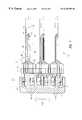
- FIG. 7shows a side view of an actuator arm stack of the present invention
- FIG. 8shows a perspective view of the arm stack of FIG. 7
- FIG. 9shows a perspective view of an alternative embodiment of the arm tool.
- FIGS. 1 and 2show schematic diagrams of the data storage system of the present invention which is designated by the general reference number 10 .
- System 10comprises a plurality of magnetic recording disks 12 . Each disk has a plurality of concentric data tracks. Disks 12 are mounted on a spindle motor shaft 14 , which is connected to a spindle motor 16 . Motor 16 is mounted to a chassis 18 . The disks 12 , spindle 14 , and motor 16 comprise a disk stack assembly 20 .
- a plurality of transducer assemblies or heads 30are positioned over the disks 12 such that each surface of the disks 12 has a corresponding head 30 .
- the head 30is comprised of an air bearing slider and read and write transducer elements.
- Each head 30is attached to one of a plurality of suspensions 32 which in turn are attached to a plurality of actuator arms 34 .
- Arms 34are connected to a rotary actuator 36 .
- the arms 34are an integral part of a rotary actuator comb.
- Actuator 36moves the heads in a radial direction across disks 12 .
- Actuator 36typically comprises a rotating member 38 mounted to a rotating bearing 40 , a motor winding 42 and motor magnets 44 .
- Actuator 36is also mounted to chassis 18 .
- the heads 30 , suspensions 32 , arms 34 and actuator 36comprise an actuator assembly 46 .
- the disk stack assembly 20 and the actuator assembly 46are sealed in an enclosure 48 (shown by a dashed line) which provides protection from particulate contamination.
- a controller unit 50provides overall control to system 10 .
- Controller unit 50typically contains a central processing unit (CPU), memory unit and other digital circuitry.
- Controller 50is connected to an actuator control/drive unit 56 which in turn is connected to actuator 36 . This allows controller 50 to control the movement of heads 30 over disks 12 .
- the controller 50is connected to a read/write channel 58 which in turn is connected to the heads 30 . This allows controller 50 to send and receive data from the disks 12 .
- Controller 50is connected to a spindle control/drive unit 60 which in turn is connected to spindle motor 16 . This allows controller 50 to control the rotation of disks 12 .
- a host system 70which is typically a computer system, is connected to the controller unit 50 .
- System 60may send digital data to controller 50 to be stored on disks 12 , or may request the digital data be read from disks 12 and sent to the system 70 .
- the basic operation of DASD unitsis well known in the art.
- FIG. 3shows a top view of a head 30 , suspension 32 and actuator arm 34 .
- the combination of these elementsshall be referred to as a suspension/arm assembly 102 .
- the suspension/arm assembly 102typically has a second suspension 32 (not shown) on its bottom surface.
- the suspension 32 and arm 34have a longitudinal axis 100 , a lateral axis 102 and a vertical axis 104 .
- Suspension 32is comprised of a load beam 110 and a laminated member 112 .
- Laminated member 112is formed from a multi-layer laminated material comprised of a steel support layer and electrically insulating layer, and an electrically conducting layer. The various layers of the laminated member 112 are etched away in a photolithographic process to form the desired shapes. Alternatively, the layers could be built up in a deposition process.
- the laminated member 112is attached to the load beam 110 .
- the load beam 110is attached to a swage member 114 . Welding or adhesive may be used as the means of attachment.
- the swage member 114is then swaged to the arm 34 .
- the suspension 32is extremely small.
- the distance from the end of the actuator arm 34 to the end of the suspensionis typically on the order of 15 mm.
- the head 30typically measures 1.25 mm ⁇ 1.00 mm ⁇ 0.3 mm.
- the electrically conducting layers and electrically insulating layersare etched to form electrical lines (or leads) 120 which run from a rear termination pad area located on a connection card 122 to the head 30 .
- the connection card 122is mounted vertically against the side of the arm 34 .
- the electrical lines 120are bent vertically at a section 124 to meet with the card 122 .
- the electrical lines 120terminate and are electrically attached to the head 30 at head termination pads which are located on the head 30 .
- the support layer of the laminated member 112is formed into a flexure member 142 at the end of the suspension 32 .
- Flexure member 142provides a gimbal mount for attachment of the head 30 .
- the gimbal mountallows the head 30 to pivot in order to adjust its orientation (static attitude) to achieve the proper air bearing between the head 30 and disk 12 while the disk 12 is rotating.
- the flexure 142 , and load beam 110also serves the purpose of providing support for the electrical lines 120 , among other purposes such as providing stiffness, balance and an area for bonding or welding.
- FIG. 4shows a plan layout top view of each of the separate elements of the suspension/arm assembly 102 of FIG. 3 .
- the head 30has been omitted in this figure.
- Laminated member 112is comprised of an electrically conducting layer 150 and electrically insulating layer 152 and a support layer 154 .
- Layers 150 , 152 and 154are layers formed from a single laminated sheet of material. In FIG. 4 each of the layers has been separated in order to better view each of their features. However, the three layers 150 , 152 and 154 are actually integrally formed together.
- the member 112is formed from the integral laminated sheet by using photolitographic etch processes as are known in the art.
- Layer 150is made of an electrically conducting material such as copper or a copper alloy.
- the materialis C7025 copper alloy and has a thickness of between 0.012 mm and 0.025 mm and preferably 0.018 mm.
- Layer 152is made of an electrically insulating material and in the preferred embodiment is made of polyimide or Teflon.
- the layerhas a thickness of between 0.010 mm and 0.025 mm and preferably 0.018 mm.
- Layer 154is made of a thin stiff material which is able to bend slightly, and in the preferred embodiment is made of 300 series stainless steel. The thickness of this layer is between 0.012 mm and 0.025 mm and preferably 0.020 mm.
- the electrical lines 120 of layer 150are formed into four separate lines 160 of two sets of two lines each. In the drawing of FIG. 4 the four separate lines 160 are not distinguishable, and only the two sets of lines are viewable.
- the lines 120start at the connection card 122 .
- Connection card 122provides connection to the read/write channel 58 .
- the connection card 122is located on the side of the actuator arm 34 when the drive is fully assembled.
- the lines 120run in a vertical plane along the side of the arm 34 in a section 124 .
- the lines 120are then bent upward and run along the top surface of the arm 34 . Lines 120 run towards the center longitudinal axis 100 of the suspension 32 . Lines 120 then run in a generally longitudinal direction towards the head 30 .
- the two sets of lines 120separate and run along either side of head 30 , then turn backward to the head 30 to terminate at the front face of head 30 at the head termination pads. This is necessary because the transducer electronics are located on the front face of the slider. This face of the slider is the trailing face as the disk rotates beneath the suspension during operation. Lines 120 are bent 90° vertically in order to interface with the pads on the head 30 .
- Layer 152is shaped to provide electrical insulation protection to the lines 120 of layer 150 which directly overlay the layer 152 .
- Layer 152forms an insulating strip directly beneath the lines 120 of layer 150 .
- layer 152is shaped into a series of pads 170 which underlie lines 120 . This is done to allow the lines 120 to be more flexible at the head area in order to minimize the change in static attitude of the head caused by the exertion of force by the lines 120 and to accommodate different temperature and humidity conditions.
- Layer 154provides support for the lines 120 . At its distal end, Layer 154 forms the flexure member 142 . Flexure 142 has a distal end 226 having a front platform 228 which provides support for lines 120 . Behind platform 228 is a flexure aperture 230 . A tongue section 232 provides support and an attachment point for head 30 . Between tongue section 232 and platform 228 are a pair of rectangular apertures 234 . Apertures 234 allow the lines 120 to bend as they approach the termination pads of head 30 .
- Load beam 110is generally flat and rigid and made of a stainless steel or other rigid material.
- the load beam 110is made of 300 series stainless steel and has a thickness of between 0.025 mm and 0.100 mm and preferably 0.051 mm. It is desirable to maintain the weight and inertia of load beam as small as possible without compromising its structural rigidity.
- Load beam 110has a depressed section 250 which is used to provide additional structural stiffness.
- Section 250has a pair of apertures 252 which are used for tool alignment during the manufacturing process.
- Another aperture 253is used to form a spring section for the load beam 110 .
- Load beam 110has a distal end with a tab 254 which is used for merge and dynamic loading and unloading of the suspension.
- An aperture 256is located behind tab 254 .
- a tongue section 258extends into aperture 256 .
- a stamped raised button or dimple 260is located on tongue 258 .
- Dimple 260contacts tongue section 232 of flexure 142 and allows head 30 (located below tongue section 32 ) to gimbal (pitch and roll) slightly such that it is able to maintain the proper air bearing orientation.
- Load beam 110is also formed by photolitographic process and the raised features are stamped. Laminated member 112 and the load beam 110 are attached by welding. Head 30 is attached to flexure tongue 232 by adhesive.
- Swage plate 114is made of stainless steel and has a thickness of between 0.100 mm and 0.200 mm and preferably 0.178 mm. Swage plate 114 has a swage spud 270 which is a raised cylindrical flange containing a cylindrical aperture.
- Arm 34is made of stainless steel or aluminum and has a thickness of between 0.8 mm and 1.0 mm and preferably 0.9 mm. Arm 34 has a distal end 272 which has an aperture 274 for receiving the spud 270 of swage plate 114 .
- Laminated member 112is formed from the three layer laminated material.
- the laminated member 112is then welded to load beam 110 .
- the load beam 110is then welded to swage plate 114 .
- the head 30is then attached to flexure 142 and the leads 120 are bonded to the head pads.
- the swage spud 270 of swage plate 114is placed in aperture 274 of arm 34 and swaged into place.
- FIG. 5shows a perspective view of the side of arm 34 .
- the connection card 122is shown having a plurality of termination pads 280 for connection to the electrical lines 120 .
- Each arm 34typically has two suspensions.
- a first top suspension 300is attached to the top surface of arm 34 and a second bottom suspension 302 is attached to a bottom surface of arm 34 .
- the laminated member 112 from both the top and bottom suspensionsare shown.
- Each laminated member 112has an electrical layer 150 containing the electrical lines 120 , an insulating layer 152 , and a support layer 154 .
- the top suspension 300is placed first. Laminated member 112 of the top suspension runs along arm 34 along a section 310 . Laminated member 112 of top suspension 300 has all three layers present in section 300 .
- the bottom suspension 302is placed next and its laminated member 112 runs along the side of arm 34 along section 124 . Section 124 includes both sections 310 and a section 312 .
- Laminated member 112 of bottom suspension 302has all three laminated layers present in section 312 , however, it has only the insulating layer 152 and electrically conducting layer 150 in section 310 .
- the supporting layer 154has been removed in section 310 .
- FIG. 6shows a cross sectional view of the overlapping suspensions 300 and 302 at section 310 .
- the top two layers(conducting layer 150 and insulating layer 152 ) are from suspension 302 .
- FIG. 7shows a side view of an actuator arm stack 400 having a plurality of actuator arms 34 .
- Each arm 34has a top and a bottom suspension 300 and 302 respectively.
- the laminated member 112 of suspension 300is bent vertically down against the side of arm 34 at section 310 .
- Support layer 154 in section 310forms a tab section 402 to provide support in section 310 .
- the laminated member 112 of suspension 302is bent vertically upward against arm 34 at section 312 .
- Support layer 154 at section 312forms a tab section 404 which provides support.
- the laminate member 112 of suspension 302continues back over section 310 , overlapping the underlying laminated member 112 from suspension 300 . This overlapping allows a more compact height design.
- Tab 402has a notched section 412 and tab 404 has a notched section 414 .
- Notch sections 412 and 414are located at the sections where the electrical lines 120 run from one surface to the side surface of arm 34 .
- the notches 412 and 414remove the support layer 154 from beneath the section. This allows the lines 120 to bend from one surface to the other without crimping and allows for a smoother transition.
- the lines 120 from both suspensions 300 and 302separate and spread out such that each of the lines 120 is directed to a separate pad 280 of card 122 .
- the pads 280are where the electrical lines 120 are electrically bonded.
- Termination tail 422provides electrostatic discharge (“ESD”) protection by shorting together the electrical lines during the manufacturing process. This prevents damage to the delicate transducer electronics of the head 30 .
- ESDelectrostatic discharge
- a tool 450has a plurality of slots 452 for receiving each tail 422 .
- the tool 450is temporarily placed against the arm stack 400 during manufacturing.
- Tool 450may be adjusted up or down until the lines 120 are correctly positioned over pads 280 .
- the lines 120are then bonded to pads 280 .
- Solder bonding, ultrasonic bonding, or conductive adhesive bondingmay be used.
- the tool 450is then removed and the remaining tails 420 are broken off.
- the tool 450is made of a rigid material which may be precisely formed. In the preferred embodiment, the tool 450 is made of stainless steel.
- the slots 452form a plurality of tines 454 which separate the slots 452 .
- the dimensions of tool 450are constrained within the dimensional requirements of the lines 120 , pads 280 and card 122 .
- the tines 452may be formed at an angle relative to the plane of the surface of card 122 in order to provide the desired angle for bonding the lines 120 to pads 280 .
- the widths of the slots 452are sized to provide for easy insertion of the tails 422 while still holding them tight enough to prevent vertical (axis 104 ) movement.
- FIG. 8shows a perspective view of the arm 34 and tool 450 . It can be seen that tool 450 has a comb shape and may be precisely adjusted up or down as desired. This insures precise positioning of the electrical lines 120 during manufacture. The tool provides a single adjustment for the plurality of lines 120 and holds them in position until they are bonded to pads 280 .
- the laminated members 112 of both top and bottom suspensions 300 and 302overlap in section 310 to save height.
- the laminated membersthen end in their termination tails 422 which have a very compact height and are notched down in comparison with the section over the pads 280 . This notched section of the termination tails 422 allows for space for a larger tine 454 width.
- FIG. 9shows a perspective view of an alternative embodiment of the tool 450 .
- the slots 454are angled upward at an angle to receive the tails 422 .
- the tines 454do not extend all the way to the bottom of the tool 450 . This allows for the notched shoulder of tails 422 to fit under the tines 454 in the correct position. It can be seen that the lines 120 are pushed downwards against pads 280 for bonding. As lines 120 are pushed downward, the tail 422 is received into its respective slot 454 and then slightly upward matching the angle of the tool slot. Once all the tails 422 are in position, the tool 450 may be moved along the vertical axis 104 to correctly position the lines 120 over pads 280 .
Landscapes
- Supporting Of Heads In Record-Carrier Devices (AREA)
Abstract
Description
Claims (10)
Priority Applications (1)
| Application Number | Priority Date | Filing Date | Title |
|---|---|---|---|
| US09/294,451US6278585B1 (en) | 1999-04-19 | 1999-04-19 | Transducer suspension termination system |
Applications Claiming Priority (1)
| Application Number | Priority Date | Filing Date | Title |
|---|---|---|---|
| US09/294,451US6278585B1 (en) | 1999-04-19 | 1999-04-19 | Transducer suspension termination system |
Publications (1)
| Publication Number | Publication Date |
|---|---|
| US6278585B1true US6278585B1 (en) | 2001-08-21 |
Family
ID=23133488
Family Applications (1)
| Application Number | Title | Priority Date | Filing Date |
|---|---|---|---|
| US09/294,451Expired - Fee RelatedUS6278585B1 (en) | 1999-04-19 | 1999-04-19 | Transducer suspension termination system |
Country Status (1)
| Country | Link |
|---|---|
| US (1) | US6278585B1 (en) |
Cited By (12)
| Publication number | Priority date | Publication date | Assignee | Title |
|---|---|---|---|---|
| US20030142444A1 (en)* | 2002-01-26 | 2003-07-31 | Bin Hua Tan | Method and apparatus for the prevention of electrostatic discharge (ESD) by a hard drive magnetic head involving the utilization of anisotropic conductive paste (ACP) in the securement to a head-gimbal assembly (HGA) |
| US6636383B1 (en)* | 2000-03-17 | 2003-10-21 | Maxtor Corporation | Disk drive actuator arm assembly with unitary flex cable |
| US20040160701A1 (en)* | 1999-11-17 | 2004-08-19 | Tdk Corporation | Magnetic head assembly having a rotational arm for electrically connecting the magnetic head to an external circuit and methods of manufacturing the same |
| US20060152854A1 (en)* | 2005-01-13 | 2006-07-13 | Arya Satya P | Method and apparatus for reducing crosstalk and signal loss in flexing interconnects of an electrical lead suspension |
| US7116523B2 (en)* | 1998-12-21 | 2006-10-03 | Hitachi Global Storage Technologies Netherlands B.V. | Interconnect module for use in a suspension assembly |
| US20070146938A1 (en)* | 2005-12-27 | 2007-06-28 | Fujitsu Limited | Head arm and information storage apparatus |
| US20070188540A1 (en)* | 2006-02-13 | 2007-08-16 | Lexmark International, Inc. | Actuator chip for inkjet printhead with electrostatic discharge protection |
| US7375927B1 (en)* | 2005-04-28 | 2008-05-20 | Hutchinson Technology Incorporated | Laminated headlift structure for disk drive suspensions |
| US20090113702A1 (en)* | 2007-11-01 | 2009-05-07 | Western Digital Technologies, Inc. | Disk drive comprising a double sided flex circuit wherein a first side lead provides an etching mask for a second side lead |
| US7804664B1 (en) | 2007-07-17 | 2010-09-28 | Hutchinson Technology Incorporated | Laminate beam transition headlift for a disk drive head suspension |
| CN1838251B (en)* | 2005-01-13 | 2010-10-13 | 日立环球储存科技荷兰有限公司 | Apparatus and method for reducing solder pad size in an electrical lead suspension |
| US20110149442A1 (en)* | 2009-12-22 | 2011-06-23 | Contreras John T | Conductor suspension structure for hard disk drives |
Citations (28)
| Publication number | Priority date | Publication date | Assignee | Title |
|---|---|---|---|---|
| JPS6469362A (en) | 1987-09-10 | 1989-03-15 | Rohm Co Ltd | Production of thermal head |
| JPS6469361A (en) | 1987-09-10 | 1989-03-15 | Rohm Co Ltd | Production of thermal head |
| JPH0239447A (en) | 1988-07-28 | 1990-02-08 | Nec Corp | Tape carrier |
| US5001591A (en) | 1988-06-03 | 1991-03-19 | Alps Electric Co., Ltd. | Thin film magnetic head |
| US5027239A (en) | 1989-12-22 | 1991-06-25 | Seagate Technology, Inc. | Routing a sleeve and conductors in a head-gimbal assembly |
| JPH05303721A (en) | 1992-01-23 | 1993-11-16 | Sanyo Electric Co Ltd | Thin-film magnetic head |
| JPH0676257A (en) | 1992-05-22 | 1994-03-18 | Nec Corp | Magnetic head |
| US5498840A (en) | 1994-04-20 | 1996-03-12 | Seagate Technology, Inc. | Transducer signal terminator |
| EP0770992A2 (en) | 1995-10-26 | 1997-05-02 | International Business Machines Corporation | Head gimbal assembly for an information storage system |
| US5631786A (en) | 1994-05-19 | 1997-05-20 | International Business Machines Corporation | Termination pad manipulator for a laminated suspension in a data storage system |
| JPH09190686A (en) | 1996-01-10 | 1997-07-22 | Toshiba Corp | Magnetic head assembly, magnetic disk manufacturing method, and magnetic disk device |
| JPH09213839A (en) | 1996-01-30 | 1997-08-15 | Nec Kyushu Ltd | Plastic package type semiconductor integrated circuit and manufacture thereof |
| US5661896A (en) | 1995-05-19 | 1997-09-02 | International Business Machines Corporation | Method of manufacturing a termination pad manipulator for a laminated suspension in a data storage system |
| US5739982A (en) | 1996-08-23 | 1998-04-14 | International Business Machines Corporation | Laser treatment of head gimbal assembly components |
| US5754370A (en) | 1995-10-12 | 1998-05-19 | International Business Machines Corporation | Wired suspension assembly in disk storage device method for assembly head suspension assembly |
| US5757585A (en) | 1996-10-15 | 1998-05-26 | International Business Machines Corporation | Method for bonding leads to a slider in a disk drive integrated suspension assembly |
| US5768068A (en) | 1996-10-08 | 1998-06-16 | Eckberg; Eric A. | Head/suspension design having fewer signal wires and making the same |
| US5781380A (en) | 1997-04-01 | 1998-07-14 | Western Digital Corporation | Swing-type actuator assembly having internal conductors |
| US5808834A (en) | 1995-06-07 | 1998-09-15 | Hutchinson Technology Incorporated | Laminated adapter |
| US5815349A (en) | 1995-09-21 | 1998-09-29 | International Business Machines Corporation | Suspension with wire protection which does not impact slider movements |
| US5835306A (en) | 1995-06-07 | 1998-11-10 | Hutchinson Technology Incorporated | Integrated gimbal suspension assembly with assymetric bond pad |
| US5844753A (en)* | 1995-04-13 | 1998-12-01 | Nippon Mektron Ltd. | Magnetic head junction board and manufacturing method for the same |
| US5844750A (en)* | 1994-03-17 | 1998-12-01 | Fujitsu Limited | Actuator arm assembly having an actuator arm wiring pattern and a head suspension wiring pattern |
| US5844751A (en) | 1994-04-15 | 1998-12-01 | Hutchinson Technology, Incorporated | Laminated structures for a disk drive suspension assembly |
| US5859749A (en) | 1995-09-25 | 1999-01-12 | Read-Rite Corporation | Flexible circuit for magnetic head assembly |
| US5862010A (en) | 1997-07-08 | 1999-01-19 | International Business Machines Corporation | Transducer suspension system |
| US5995322A (en)* | 1996-09-19 | 1999-11-30 | Kabushiki Kaisha Toshiba | Magnetic disk apparatus |
| US6163443A (en)* | 1998-02-19 | 2000-12-19 | Fujitsu Limited | Actuator having MR element protecting means |
- 1999
- 1999-04-19USUS09/294,451patent/US6278585B1/ennot_activeExpired - Fee Related
Patent Citations (28)
| Publication number | Priority date | Publication date | Assignee | Title |
|---|---|---|---|---|
| JPS6469362A (en) | 1987-09-10 | 1989-03-15 | Rohm Co Ltd | Production of thermal head |
| JPS6469361A (en) | 1987-09-10 | 1989-03-15 | Rohm Co Ltd | Production of thermal head |
| US5001591A (en) | 1988-06-03 | 1991-03-19 | Alps Electric Co., Ltd. | Thin film magnetic head |
| JPH0239447A (en) | 1988-07-28 | 1990-02-08 | Nec Corp | Tape carrier |
| US5027239A (en) | 1989-12-22 | 1991-06-25 | Seagate Technology, Inc. | Routing a sleeve and conductors in a head-gimbal assembly |
| JPH05303721A (en) | 1992-01-23 | 1993-11-16 | Sanyo Electric Co Ltd | Thin-film magnetic head |
| JPH0676257A (en) | 1992-05-22 | 1994-03-18 | Nec Corp | Magnetic head |
| US5844750A (en)* | 1994-03-17 | 1998-12-01 | Fujitsu Limited | Actuator arm assembly having an actuator arm wiring pattern and a head suspension wiring pattern |
| US5844751A (en) | 1994-04-15 | 1998-12-01 | Hutchinson Technology, Incorporated | Laminated structures for a disk drive suspension assembly |
| US5498840A (en) | 1994-04-20 | 1996-03-12 | Seagate Technology, Inc. | Transducer signal terminator |
| US5631786A (en) | 1994-05-19 | 1997-05-20 | International Business Machines Corporation | Termination pad manipulator for a laminated suspension in a data storage system |
| US5844753A (en)* | 1995-04-13 | 1998-12-01 | Nippon Mektron Ltd. | Magnetic head junction board and manufacturing method for the same |
| US5661896A (en) | 1995-05-19 | 1997-09-02 | International Business Machines Corporation | Method of manufacturing a termination pad manipulator for a laminated suspension in a data storage system |
| US5808834A (en) | 1995-06-07 | 1998-09-15 | Hutchinson Technology Incorporated | Laminated adapter |
| US5835306A (en) | 1995-06-07 | 1998-11-10 | Hutchinson Technology Incorporated | Integrated gimbal suspension assembly with assymetric bond pad |
| US5815349A (en) | 1995-09-21 | 1998-09-29 | International Business Machines Corporation | Suspension with wire protection which does not impact slider movements |
| US5859749A (en) | 1995-09-25 | 1999-01-12 | Read-Rite Corporation | Flexible circuit for magnetic head assembly |
| US5754370A (en) | 1995-10-12 | 1998-05-19 | International Business Machines Corporation | Wired suspension assembly in disk storage device method for assembly head suspension assembly |
| EP0770992A2 (en) | 1995-10-26 | 1997-05-02 | International Business Machines Corporation | Head gimbal assembly for an information storage system |
| JPH09190686A (en) | 1996-01-10 | 1997-07-22 | Toshiba Corp | Magnetic head assembly, magnetic disk manufacturing method, and magnetic disk device |
| JPH09213839A (en) | 1996-01-30 | 1997-08-15 | Nec Kyushu Ltd | Plastic package type semiconductor integrated circuit and manufacture thereof |
| US5739982A (en) | 1996-08-23 | 1998-04-14 | International Business Machines Corporation | Laser treatment of head gimbal assembly components |
| US5995322A (en)* | 1996-09-19 | 1999-11-30 | Kabushiki Kaisha Toshiba | Magnetic disk apparatus |
| US5768068A (en) | 1996-10-08 | 1998-06-16 | Eckberg; Eric A. | Head/suspension design having fewer signal wires and making the same |
| US5757585A (en) | 1996-10-15 | 1998-05-26 | International Business Machines Corporation | Method for bonding leads to a slider in a disk drive integrated suspension assembly |
| US5781380A (en) | 1997-04-01 | 1998-07-14 | Western Digital Corporation | Swing-type actuator assembly having internal conductors |
| US5862010A (en) | 1997-07-08 | 1999-01-19 | International Business Machines Corporation | Transducer suspension system |
| US6163443A (en)* | 1998-02-19 | 2000-12-19 | Fujitsu Limited | Actuator having MR element protecting means |
Cited By (20)
| Publication number | Priority date | Publication date | Assignee | Title |
|---|---|---|---|---|
| US7116523B2 (en)* | 1998-12-21 | 2006-10-03 | Hitachi Global Storage Technologies Netherlands B.V. | Interconnect module for use in a suspension assembly |
| US20040160701A1 (en)* | 1999-11-17 | 2004-08-19 | Tdk Corporation | Magnetic head assembly having a rotational arm for electrically connecting the magnetic head to an external circuit and methods of manufacturing the same |
| US6636383B1 (en)* | 2000-03-17 | 2003-10-21 | Maxtor Corporation | Disk drive actuator arm assembly with unitary flex cable |
| US8159790B2 (en)* | 2002-01-26 | 2012-04-17 | Sae Magnetics (H.K.) Ltd. | Method and apparatus for the prevention of electrostatic discharge (ESD) by a hard drive magnetic head involving the utilization of anisotropic conductive paste (ACP) in the securement to a head-gimbal assembly (HGA) |
| US20030142444A1 (en)* | 2002-01-26 | 2003-07-31 | Bin Hua Tan | Method and apparatus for the prevention of electrostatic discharge (ESD) by a hard drive magnetic head involving the utilization of anisotropic conductive paste (ACP) in the securement to a head-gimbal assembly (HGA) |
| CN1838251B (en)* | 2005-01-13 | 2010-10-13 | 日立环球储存科技荷兰有限公司 | Apparatus and method for reducing solder pad size in an electrical lead suspension |
| US20060152854A1 (en)* | 2005-01-13 | 2006-07-13 | Arya Satya P | Method and apparatus for reducing crosstalk and signal loss in flexing interconnects of an electrical lead suspension |
| US7352535B2 (en)* | 2005-01-13 | 2008-04-01 | Hitachi Global Storage Technologies Netherlands, B.V. | Method and apparatus for reducing crosstalk and signal loss in flexing interconnects of an electrical lead suspension |
| CN1838250B (en)* | 2005-01-13 | 2010-12-29 | 日立环球储存科技荷兰有限公司 | Method and apparatus for reducing crosstalk and signal loss in flexing interconnects of an electrical lead suspension |
| US7375927B1 (en)* | 2005-04-28 | 2008-05-20 | Hutchinson Technology Incorporated | Laminated headlift structure for disk drive suspensions |
| US20070146938A1 (en)* | 2005-12-27 | 2007-06-28 | Fujitsu Limited | Head arm and information storage apparatus |
| WO2007095380A3 (en)* | 2006-02-13 | 2009-04-09 | Lexmark Int Inc | Actuator chip for inkjet printhead with electrostatic discharge protection |
| US7361966B2 (en)* | 2006-02-13 | 2008-04-22 | Lexmark International, Inc. | Actuator chip for inkjet printhead with electrostatic discharge protection |
| US20070188540A1 (en)* | 2006-02-13 | 2007-08-16 | Lexmark International, Inc. | Actuator chip for inkjet printhead with electrostatic discharge protection |
| US7804664B1 (en) | 2007-07-17 | 2010-09-28 | Hutchinson Technology Incorporated | Laminate beam transition headlift for a disk drive head suspension |
| US20090113702A1 (en)* | 2007-11-01 | 2009-05-07 | Western Digital Technologies, Inc. | Disk drive comprising a double sided flex circuit wherein a first side lead provides an etching mask for a second side lead |
| US20110226729A1 (en)* | 2007-11-01 | 2011-09-22 | Western Digital Technologies, Inc. | Method of manufacturing a double sided flex circuit for a disk drive wherein a first side lead provides an etching mask for a second side lead |
| US9060420B2 (en) | 2007-11-01 | 2015-06-16 | Western Digitial Technologies, Inc. | Method of manufacturing a double sided flex circuit for a disk drive wherein a first side lead provides an etching mask for a second side lead |
| US20110149442A1 (en)* | 2009-12-22 | 2011-06-23 | Contreras John T | Conductor suspension structure for hard disk drives |
| US8310789B2 (en)* | 2009-12-22 | 2012-11-13 | Hitachi Global Storage Technologies Netherlands B.V. | Conductor suspension structure and electrical connection assembly for transmitting complementary signals in a hard disk drive |
Similar Documents
| Publication | Publication Date | Title |
|---|---|---|
| US6243235B1 (en) | Transducer suspension system with limiter | |
| US5986853A (en) | Transducer suspension system | |
| JP3415968B2 (en) | Suspension system | |
| EP0888610B1 (en) | Adjustable solder bump spacer for slider-suspension attachment | |
| US6442828B1 (en) | Method of manufacturing a transducer suspension system | |
| US6700747B2 (en) | Integrated lead head suspension assembly having an etched laminated load beam and flexure with deposited conductors | |
| US5818662A (en) | Static attitude and stiffness control for an integrated suspension | |
| US5969906A (en) | Transducer suspension system having access aperture | |
| US5872687A (en) | Transducer suspension system | |
| USRE37869E1 (en) | Head signal supply/retrieval structure for magnetic disc drive | |
| KR100288806B1 (en) | Integrated head-electronics interconnection suspension for a data recording disk drive | |
| CN1136543C (en) | Integrated suspending frame flexible parts with flexible terminal platform | |
| US5570261A (en) | Transducer suspension system | |
| US20080225439A1 (en) | Magnetic head actuator assembly | |
| US20040027725A1 (en) | Integrated lead suspension for high density drive | |
| US5909342A (en) | Planar flexible circuit package for coupling transducers with carriage mounted circuitry | |
| US7130157B2 (en) | Head suspension having a displacement limiter | |
| US6278585B1 (en) | Transducer suspension termination system | |
| CN113140231A (en) | Suspension assembly and disk device | |
| US6985332B1 (en) | Head gimbal assembly with flex circuit arrangement between slider and head interconnect assembly | |
| US5956208A (en) | Magnetic head device having bent terminal lead wires for establishing an electrical connection with a magnetic head on a slider | |
| US6411469B1 (en) | Transducer suspension system with high conductivity leads having two layers | |
| US6181527B1 (en) | Transducer suspension system including a frequency dependent shunt |
Legal Events
| Date | Code | Title | Description |
|---|---|---|---|
| AS | Assignment | Owner name:INTERNATIONAL BUSINESS MACHINES CORPORATION, NEW Y Free format text:ASSIGNMENT OF ASSIGNORS INTEREST;ASSIGNORS:OLSON, STEPHEN ARNOLD;PALMER, DARRELL DEAN;VESCI, ANTHONY;REEL/FRAME:009911/0366 Effective date:19990419 | |
| AS | Assignment | Owner name:MARIANA HDD B.V., NETHERLANDS Free format text:ASSIGNMENT OF ASSIGNORS INTEREST;ASSIGNOR:INTERNATIONAL BUSINESS MACHINES CORPORATION;REEL/FRAME:013663/0348 Effective date:20021231 | |
| AS | Assignment | Owner name:HITACHI GLOBAL STORAGE TECHNOLOGIES NETHERLANDS B. Free format text:CHANGE OF NAME;ASSIGNOR:MARIANA HDD B.V.;REEL/FRAME:013746/0146 Effective date:20021231 | |
| FEPP | Fee payment procedure | Free format text:PAYOR NUMBER ASSIGNED (ORIGINAL EVENT CODE: ASPN); ENTITY STATUS OF PATENT OWNER: LARGE ENTITY | |
| FPAY | Fee payment | Year of fee payment:4 | |
| REMI | Maintenance fee reminder mailed | ||
| LAPS | Lapse for failure to pay maintenance fees | ||
| LAPS | Lapse for failure to pay maintenance fees | Free format text:PATENT EXPIRED FOR FAILURE TO PAY MAINTENANCE FEES (ORIGINAL EVENT CODE: EXP.); ENTITY STATUS OF PATENT OWNER: LARGE ENTITY | |
| STCH | Information on status: patent discontinuation | Free format text:PATENT EXPIRED DUE TO NONPAYMENT OF MAINTENANCE FEES UNDER 37 CFR 1.362 | |
| FP | Lapsed due to failure to pay maintenance fee | Effective date:20090821 |