US6278532B1 - Apparatus and method for reception and transmission of information using different protocols - Google Patents
Apparatus and method for reception and transmission of information using different protocolsDownload PDFInfo
- Publication number
- US6278532B1 US6278532B1US08/770,775US77077596AUS6278532B1US 6278532 B1US6278532 B1US 6278532B1US 77077596 AUS77077596 AUS 77077596AUS 6278532 B1US6278532 B1US 6278532B1
- Authority
- US
- United States
- Prior art keywords
- information
- destination
- protocol
- session
- incoming information
- Prior art date
- Legal status (The legal status is an assumption and is not a legal conclusion. Google has not performed a legal analysis and makes no representation as to the accuracy of the status listed.)
- Expired - Lifetime
Links
Images


Classifications
- H—ELECTRICITY
- H04—ELECTRIC COMMUNICATION TECHNIQUE
- H04N—PICTORIAL COMMUNICATION, e.g. TELEVISION
- H04N1/00—Scanning, transmission or reproduction of documents or the like, e.g. facsimile transmission; Details thereof
- H04N1/32—Circuits or arrangements for control or supervision between transmitter and receiver or between image input and image output device, e.g. between a still-image camera and its memory or between a still-image camera and a printer device
- H04N1/32358—Circuits or arrangements for control or supervision between transmitter and receiver or between image input and image output device, e.g. between a still-image camera and its memory or between a still-image camera and a printer device using picture signal storage, e.g. at transmitter
- H04N1/324—Circuits or arrangements for control or supervision between transmitter and receiver or between image input and image output device, e.g. between a still-image camera and its memory or between a still-image camera and a printer device using picture signal storage, e.g. at transmitter intermediate the transmitter and receiver terminals, e.g. at an exchange
- H04N1/32406—Circuits or arrangements for control or supervision between transmitter and receiver or between image input and image output device, e.g. between a still-image camera and its memory or between a still-image camera and a printer device using picture signal storage, e.g. at transmitter intermediate the transmitter and receiver terminals, e.g. at an exchange in connection with routing or relaying, e.g. using a fax-server or a store-and-forward facility
- H04N1/32411—Handling instructions for routing or relaying
- H—ELECTRICITY
- H04—ELECTRIC COMMUNICATION TECHNIQUE
- H04L—TRANSMISSION OF DIGITAL INFORMATION, e.g. TELEGRAPHIC COMMUNICATION
- H04L51/00—User-to-user messaging in packet-switching networks, transmitted according to store-and-forward or real-time protocols, e.g. e-mail
- H04L51/06—Message adaptation to terminal or network requirements
- H04L51/066—Format adaptation, e.g. format conversion or compression
- H—ELECTRICITY
- H04—ELECTRIC COMMUNICATION TECHNIQUE
- H04N—PICTORIAL COMMUNICATION, e.g. TELEVISION
- H04N1/00—Scanning, transmission or reproduction of documents or the like, e.g. facsimile transmission; Details thereof
- H04N1/00127—Connection or combination of a still picture apparatus with another apparatus, e.g. for storage, processing or transmission of still picture signals or of information associated with a still picture
- H04N1/00204—Connection or combination of a still picture apparatus with another apparatus, e.g. for storage, processing or transmission of still picture signals or of information associated with a still picture with a digital computer or a digital computer system, e.g. an internet server
- H04N1/00209—Transmitting or receiving image data, e.g. facsimile data, via a computer, e.g. using e-mail, a computer network, the internet, I-fax
- H—ELECTRICITY
- H04—ELECTRIC COMMUNICATION TECHNIQUE
- H04N—PICTORIAL COMMUNICATION, e.g. TELEVISION
- H04N1/00—Scanning, transmission or reproduction of documents or the like, e.g. facsimile transmission; Details thereof
- H04N1/32—Circuits or arrangements for control or supervision between transmitter and receiver or between image input and image output device, e.g. between a still-image camera and its memory or between a still-image camera and a printer device
- H04N1/32358—Circuits or arrangements for control or supervision between transmitter and receiver or between image input and image output device, e.g. between a still-image camera and its memory or between a still-image camera and a printer device using picture signal storage, e.g. at transmitter
- H04N1/324—Circuits or arrangements for control or supervision between transmitter and receiver or between image input and image output device, e.g. between a still-image camera and its memory or between a still-image camera and a printer device using picture signal storage, e.g. at transmitter intermediate the transmitter and receiver terminals, e.g. at an exchange
- H04N1/32432—Circuits or arrangements for control or supervision between transmitter and receiver or between image input and image output device, e.g. between a still-image camera and its memory or between a still-image camera and a printer device using picture signal storage, e.g. at transmitter intermediate the transmitter and receiver terminals, e.g. at an exchange in a particular memory file for retrieval by the user, e.g. in a facsimile mailbox
- H—ELECTRICITY
- H04—ELECTRIC COMMUNICATION TECHNIQUE
- H04N—PICTORIAL COMMUNICATION, e.g. TELEVISION
- H04N1/00—Scanning, transmission or reproduction of documents or the like, e.g. facsimile transmission; Details thereof
- H04N1/32—Circuits or arrangements for control or supervision between transmitter and receiver or between image input and image output device, e.g. between a still-image camera and its memory or between a still-image camera and a printer device
- H04N1/333—Mode signalling or mode changing; Handshaking therefor
- H04N1/33307—Mode signalling or mode changing; Handshaking therefor prior to start of transmission, input or output of the picture signal only
- H04N1/33323—Mode signalling or mode changing; Handshaking therefor prior to start of transmission, input or output of the picture signal only transmission mode only, e.g. speed
- H—ELECTRICITY
- H04—ELECTRIC COMMUNICATION TECHNIQUE
- H04N—PICTORIAL COMMUNICATION, e.g. TELEVISION
- H04N1/00—Scanning, transmission or reproduction of documents or the like, e.g. facsimile transmission; Details thereof
- H04N1/32—Circuits or arrangements for control or supervision between transmitter and receiver or between image input and image output device, e.g. between a still-image camera and its memory or between a still-image camera and a printer device
- H04N1/333—Mode signalling or mode changing; Handshaking therefor
- H04N1/33346—Mode signalling or mode changing; Handshaking therefor adapting to a particular standardised protocol
- H—ELECTRICITY
- H04—ELECTRIC COMMUNICATION TECHNIQUE
- H04N—PICTORIAL COMMUNICATION, e.g. TELEVISION
- H04N1/00—Scanning, transmission or reproduction of documents or the like, e.g. facsimile transmission; Details thereof
- H04N1/32—Circuits or arrangements for control or supervision between transmitter and receiver or between image input and image output device, e.g. between a still-image camera and its memory or between a still-image camera and a printer device
- H04N1/333—Mode signalling or mode changing; Handshaking therefor
- H04N1/33376—Mode signalling or mode changing; Handshaking therefor according to characteristics or state of one of the communicating parties, e.g. available memory capacity
- H—ELECTRICITY
- H04—ELECTRIC COMMUNICATION TECHNIQUE
- H04L—TRANSMISSION OF DIGITAL INFORMATION, e.g. TELEGRAPHIC COMMUNICATION
- H04L51/00—User-to-user messaging in packet-switching networks, transmitted according to store-and-forward or real-time protocols, e.g. e-mail
- H—ELECTRICITY
- H04—ELECTRIC COMMUNICATION TECHNIQUE
- H04N—PICTORIAL COMMUNICATION, e.g. TELEVISION
- H04N1/00—Scanning, transmission or reproduction of documents or the like, e.g. facsimile transmission; Details thereof
- H04N1/32—Circuits or arrangements for control or supervision between transmitter and receiver or between image input and image output device, e.g. between a still-image camera and its memory or between a still-image camera and a printer device
- H04N1/32101—Display, printing, storage or transmission of additional information, e.g. ID code, date and time or title
- H04N1/32106—Display, printing, storage or transmission of additional information, e.g. ID code, date and time or title separate from the image data, e.g. in a different computer file
- H04N1/32112—Display, printing, storage or transmission of additional information, e.g. ID code, date and time or title separate from the image data, e.g. in a different computer file in a separate computer file, document page or paper sheet, e.g. a fax cover sheet
- H—ELECTRICITY
- H04—ELECTRIC COMMUNICATION TECHNIQUE
- H04N—PICTORIAL COMMUNICATION, e.g. TELEVISION
- H04N2201/00—Indexing scheme relating to scanning, transmission or reproduction of documents or the like, and to details thereof
- H04N2201/0008—Connection or combination of a still picture apparatus with another apparatus
- H04N2201/0015—Control of image communication with the connected apparatus, e.g. signalling capability
- H04N2201/002—Selecting or switching between an image communication channel and a non-image communication channel
- H—ELECTRICITY
- H04—ELECTRIC COMMUNICATION TECHNIQUE
- H04N—PICTORIAL COMMUNICATION, e.g. TELEVISION
- H04N2201/00—Indexing scheme relating to scanning, transmission or reproduction of documents or the like, and to details thereof
- H04N2201/0008—Connection or combination of a still picture apparatus with another apparatus
- H04N2201/0034—Details of the connection, e.g. connector, interface
- H04N2201/0037—Topological details of the connection
- H04N2201/0039—Connection via a network
- H—ELECTRICITY
- H04—ELECTRIC COMMUNICATION TECHNIQUE
- H04N—PICTORIAL COMMUNICATION, e.g. TELEVISION
- H04N2201/00—Indexing scheme relating to scanning, transmission or reproduction of documents or the like, and to details thereof
- H04N2201/0008—Connection or combination of a still picture apparatus with another apparatus
- H04N2201/0034—Details of the connection, e.g. connector, interface
- H04N2201/0037—Topological details of the connection
- H04N2201/0041—Point to point
- H—ELECTRICITY
- H04—ELECTRIC COMMUNICATION TECHNIQUE
- H04N—PICTORIAL COMMUNICATION, e.g. TELEVISION
- H04N2201/00—Indexing scheme relating to scanning, transmission or reproduction of documents or the like, and to details thereof
- H04N2201/0077—Types of the still picture apparatus
- H04N2201/0093—Facsimile machine
- H—ELECTRICITY
- H04—ELECTRIC COMMUNICATION TECHNIQUE
- H04N—PICTORIAL COMMUNICATION, e.g. TELEVISION
- H04N2201/00—Indexing scheme relating to scanning, transmission or reproduction of documents or the like, and to details thereof
- H04N2201/32—Circuits or arrangements for control or supervision between transmitter and receiver or between image input and image output device, e.g. between a still-image camera and its memory or between a still-image camera and a printer device
- H04N2201/3201—Display, printing, storage or transmission of additional information, e.g. ID code, date and time or title
- H04N2201/3202—Display, printing, storage or transmission of additional information, e.g. ID code, date and time or title of communication or activity log or report
- H—ELECTRICITY
- H04—ELECTRIC COMMUNICATION TECHNIQUE
- H04N—PICTORIAL COMMUNICATION, e.g. TELEVISION
- H04N2201/00—Indexing scheme relating to scanning, transmission or reproduction of documents or the like, and to details thereof
- H04N2201/32—Circuits or arrangements for control or supervision between transmitter and receiver or between image input and image output device, e.g. between a still-image camera and its memory or between a still-image camera and a printer device
- H04N2201/3201—Display, printing, storage or transmission of additional information, e.g. ID code, date and time or title
- H04N2201/3204—Display, printing, storage or transmission of additional information, e.g. ID code, date and time or title of data relating to a user, sender, addressee, machine or electronic recording medium
- H04N2201/3205—Display, printing, storage or transmission of additional information, e.g. ID code, date and time or title of data relating to a user, sender, addressee, machine or electronic recording medium of identification information, e.g. name or ID code
- H—ELECTRICITY
- H04—ELECTRIC COMMUNICATION TECHNIQUE
- H04N—PICTORIAL COMMUNICATION, e.g. TELEVISION
- H04N2201/00—Indexing scheme relating to scanning, transmission or reproduction of documents or the like, and to details thereof
- H04N2201/32—Circuits or arrangements for control or supervision between transmitter and receiver or between image input and image output device, e.g. between a still-image camera and its memory or between a still-image camera and a printer device
- H04N2201/333—Mode signalling or mode changing; Handshaking therefor
- H04N2201/33307—Mode signalling or mode changing; Handshaking therefor of a particular mode
- H04N2201/33342—Mode signalling or mode changing; Handshaking therefor of a particular mode of transmission mode
- H04N2201/33364—Type of modulation; Type of channel, e.g. digital or analog; Type of communication, e.g. half-duplex or full-duplex
- H—ELECTRICITY
- H04—ELECTRIC COMMUNICATION TECHNIQUE
- H04N—PICTORIAL COMMUNICATION, e.g. TELEVISION
- H04N2201/00—Indexing scheme relating to scanning, transmission or reproduction of documents or the like, and to details thereof
- H04N2201/32—Circuits or arrangements for control or supervision between transmitter and receiver or between image input and image output device, e.g. between a still-image camera and its memory or between a still-image camera and a printer device
- H04N2201/333—Mode signalling or mode changing; Handshaking therefor
- H04N2201/33307—Mode signalling or mode changing; Handshaking therefor of a particular mode
- H04N2201/33378—Type or format of data, e.g. colour or B/W, halftone or binary, computer image file or facsimile data
Definitions
- the present inventionrelates generally to information transfer, and in particular to apparatus and methods for sending and receiving information to and from multiple types of devices and communications media.
- E-mailelectronic mail
- facsimilefacsimile
- computer networksexist to transfer information between computers. Examples include local area networks, wide area networks, local area networks, intranets and the Internet.
- An estimated 60 billion pages of documentswill be transmitted from U.S. fax machines in 1996, and that figure is expected to double before the end of the decade.
- the fax machineis frequently taken for granted, or even ignored, in corporate communications and computer networks. While computer-generated faxes have been used to advantage in specific applications and circumstances, communications via facsimile has not been as popular in the world of local area and wide area networks and information integration.
- E-mailis frequently used, but only in very specific circumstances. People are habit-prone to using one or the other for communicating with another person, and the recipient really has no choice in how information is received. This results in a need for people to monitor a variety of communication media each having different types of information forms of protocol and data. Moreover, the types of protocol and data may be multiplied if many communications media are used. Therefore, the use of each form of communication is constrained in many ways.
- HTTPHyperText Transfer Protocol
- Web servers and Web browsershave revolutionized many areas of business.
- the Internethas brought a critical mass of information content, including communications, into the corporate environment.
- Productssuch as Java, ActiveX controls, and client/server applications are revolutionizing how business is conducted with customers and vendors.
- the Internetmakes it possible to connect throughout the world for the cost of a local connection. “Everyone” is paying for their small connection piece, and the result is a vast network that no one individual could afford. Changes to operating systems now make accessing Internet resources as simple and easy as accessing a local device.
- Groupware computingallows multiple users to share information in a cooperative fashion.
- Remote access computingallows users to dial in by standard telephone lines while away from the office and operate as though they were connected to the computer network in the office.
- fax machinesare not typically connected to corporate computer networks at all.
- known methods of such connectionshave significant disadvantages.
- One methodfor example, used a “fax/modem.”
- fax machines and fax/modems connected to personal computersrequire a telephone line to communicate to the outside world.
- Telephone linesmay or may not be part of a corporate computer communication system.
- integration of faxing into the corporate information structureis practically non-existent.
- a fax/modemis useful in sending faxes of computer-generated documents.
- itis to difficult, time consuming, and expensive to convert paper documents to electronic form using scanners and disk storage. It is far easier to print the electronic document, combine them with the paper ones, and drop them into the nearest fax machine.
- computer screensare an inferior way to display document pages, thus important documents received by a computer via fax/modem are typically printed and treated as paper documents.
- a fax serverthat is, a computer-equipped fax with multiple fax ports to send and receive faxes, and specialized software for routing an incoming fax and delivering it to the appropriate client connected fax machine.
- fax servershandle large volumes of fax traffic, thus justifying the high initial costs by spreading costs over a large number of users.
- Fax serversalso have a number of drawbacks, however. They are not cost effective for applications serving less than a high number of users, making them inappropriate for branch office locations or in specialized department locations. Moreover, fax servers are merely powerful versions of computers with fax/modems, so many of the drawbacks of PCs with fax/modems apply to fax servers as well.
- senders and receivers of informationhave very few choices in the form of communication of information. That is, senders of E-mail must send messages to an E-mail box. Receivers of E-mail must retrieve the E-mail from the E-mail box. Senders of faxes must send to a computer or a fax machine. Receivers of faxes must convert the fax in the computer or print the fax out on the fax machine. It is therefore desirable to provide methods and apparatus to facilitate integration of a fax machine into corporate communications networks while minimizing the problems of the prior art.
- the present inventionrelates to reception and transmission of information.
- the inventioncomprises apparatus including a plurality of interfaces; means for receiving incoming information having a first protocol and first data over one of the interfaces; means for analyzing the incoming information to determine a destination; means for processing the incoming information in accordance with the determined destination to create outgoing information having a protocol and data specifically for the destination; and means for transmitting the outgoing information to the destination.
- the present inventionis also directed to methods for carrying out these functions.
- FIG. 1shows a system overview of a Network Protocol Fax Box (PFB) which constitutes a preferred embodiment of the invention.
- PFBNetwork Protocol Fax Box
- FIG. 2shows a computer system which may be used to implement the PFB of FIG. 1 .
- FIG. 3is a block diagram showing the relationships among the objects of the PFB.
- FIGS. 4 and 5show the overall object processing performed by the PFB.
- FIG. 6shows a block diagram of the session object in accordance with a preferred embodiment of the invention.
- FIG. 7shows the general session object processing performed in response to receiving information at the PFB.
- FIG. 8is a block diagram showing an architecture of the destination object in accordance with a preferred embodiment of the invention.
- FIG. 9is a block diagram showing a destination determination data structure used by objects of FIGS. 4 and 5.
- FIG. 10is a block diagram showing the mailbox system in accordance with a preferred embodiment of the present invention.
- FIG. 11is a flow chart showing object processing for performing a PFB connection.
- FIG. 12is a flow chart showing point-to-point protocol connection determination.
- FIG. 13is a block diagram showing another preferred embodiment architecture using the PFB in accordance with the present invention.
- FIG. 14is a flow chart showing processing required to respond to notification from an agent that e-mail has arrived.
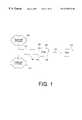
- FIG. 1shows a Network Protocol Fax Box (PFB) 110 which constitutes a preferred embodiment of the invention.
- PFB 110is connected to a fax machine 116 , such as a standard Group 3 machine, via an interface 132 and a communications line 114 .
- PFB 110receives fax information from fax machine 116 and sends fax information to fax machine 116 over communications line 114 .
- communications line 114is implemented as a standard two-conductor cable commonly used for telephone wiring.
- PFB 110may also be connected to multiple fax machines using separate interfaces and communications lines, or over a local area network (not shown).
- PFB 110is also connected to a telephone network 124 by an interface 128 and a communications line 112 .
- PFB 110is connected to telephone network 124 through a telephone jack.
- FIG. 1shows a single line connected to a single telephone network, PFB 110 may also be connected to several telephone networks.
- Telephone network 124may be any type of network which carries telephone communications, such as a public switched, cellular, or PBX telephone network. If telephone network 124 is a cellular telephone network, communications line 112 and interface 128 are implemented as a wireless link from PFB 110 to telephone network 124 .
- PFB 110is also connected to a computer network 122 via an interface 120 and a communications line 118 .
- FIG. 1shows a single line to a single network, PFB 110 may be connected several computer networks.
- the computer network 122could be any computer network, such as the Internet or an intranet.
- Computer network 122 , communications line 118 , and interface 120are implemented using standard protocols for transmitting information on computer networks.
- PFB 110coordinates reception of information from various types of sources over various types of communications lines, and transmission of the information to various types of destinations over various types of communications lines, using protocols which are required by the sources, destinations and communications lines.
- informationincludes transmission signals which have a protocol and data.
- protocolis used herein in its broad sense as a set of procedures and data formats to implement communications between communication devices over a communications medium.
- information processed by PFB 1may have an Ethernet protocol, an Internet protocol, an E-mail protocol, or a fax protocol.
- Informationmay include more than one protocol if it must be transmitted over several media. Transmission of the information by PFB 110 may include the process of translating both the protocol and the data of the information, if necessary.
- the data portion of the informationis the content of the information which is being transmitted from a source to one or more destinations.
- Datamay have various formats, such as ASCII text or facsimile. Therefore, PFB 110 translation of information protocol and data may, for example, involve translation of an Ethernet protocol to an Internet protocol, as well as translation from fax data to E-mail data.
- PFB 110allows fax machine 116 to send a fax to other fax machines, to destinations on computer network 122 , and to destinations on telephone network 124 .
- PFB 110also allows faxes and E-mail to be sent from telephone network 124 and computer network 122 to fax machine 116 , to other fax machines, or to another telephone network and computer network.
- PFB 110generally uses data and programs stored in PFB 110 to process incoming information. However, PFB 110 may also download data and programs from computer network 122 and telephone network 124 . PFB 110 may also request that devices on computer network 122 and telephone network 124 store data and run programs. By operating PFB 110 this way, as a “thin client,” storage and processing requirements of PFB 110 are reduced. This also reduces maintenance procedures such as updating software in PFB 110 because new programs and information can be automatically updated at the remote sites for use by, or downloading to, PFB 110 . Therefore, with respect to the discussion which follows, it should be kept in mind that the programs and data for implementing the operations of PFB 110 may reside locally at PFB 110 , or may be located on the telephone or computer networks. Programs and data can therefore be distributed among PFB 110 , computer network 122 and telephone network 124 , and the distribution may change dynamically.
- FIG. 2shows a computer system which may be used to implement PFB 110 .
- PFB 110is driven by a processor 210 , which is connected to several storage and interfacing devices via a bus 212 .
- Storage devicesinclude a mass store 220 , a RAM 224 , and memory in processor 210 (not shown). These storage devices store some or all of the programs and data necessary for carrying out the functions of the preferred embodiments of the invention.
- PFB 11 Oalso includes at least one telephone interface 214 and at least one computer network interface 216 .
- Telephone interface 214 and network interface 216respectively correspond to telephone interface 128 and network interface 120 of FIG. 1 .
- PFB 110preferably includes several types of telephone and network interfaces, only one example of each is included in FIG. 2 for clarity. These interfaces include the hardware and software necessary to carry out interfacing between PFB 110 and the networks.
- PFB 110also includes a facsimile interface 228 , corresponding to interface 132 of FIG. 1 .
- Facsimile interface 228receives fax information from fax machine 116 , and transmits fax information to fax machine 116 .
- An input/output device 218is provided and may comprise any well-known communications adaptor or user peripheral interface.
- a display 222displays information related to the operation of PFB 110 and may comprise, for example, a simple LCD display or a more complex graphical user interface.
- Mass store 220in a preferred embodiment comprises a hard disk drive, but may also be implemented using a RAID system, tape drive, or other mass storage device.
- PFB 110 shown in FIG. 2 in a preferred embodimentis implemented on a personal computer, such as a Compaq prolinea, or work station, such as a Sun Sparc.
- the operating system in a preferred embodimentis implemented using the RTXE operating system or a similar multitasking, multithreaded, real-time operating system.
- the functions of PFB 110are implemented using “object-oriented” software, the principles of which are well-established.
- objectsunits of software, known as “objects,” are programmed to interact in specified ways to achieve desired functionality.
- classesof objects, that is, groups of objects sharing a common structure and common behavior.
- the object-oriented architecture of PFB 110creates a flexible system which may be easily modified and upgraded by adding or replacing objects in the PFB 110 and on the networks.
- the inventionmay be practiced using other types of software, as is well-known to those skilled in the software art.
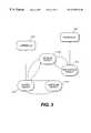
- FIG. 3is a software block diagram showing four objects from three primary object classes which are used in implementing a preferred embodiment of PFB 110 .
- PFB 110uses the three primary object classes, an interface class, a message class, and a session class, to receive information from a source and transfer the information to a destination.
- PFB 110uses a source object 312 , a message object 314 , a session object 316 , and a destination object 318 .
- Source object 312 and destination object 318are each examples of the interface class.
- a “session”begins when PFB 110 starts receiving incoming information and ends when transmission of the information, and final session procedures are finished. Information can arrive at PFB 110 simultaneously from multiple sources, and multiple sessions can be underway at any time. Each session has a source object 312 , a session object 316 , and at least one destination object 318 .
- Interface 310which corresponds to any of interfaces 214 , 228 or 216 of FIG. 2, communicates with source object 312 to transfer incoming information to source object 312 .
- Interface 320which also corresponds to any of interfaces 214 , 228 or 216 of FIG. 2, communicates with destination object 318 to transfer information to a destination.
- Each of source object 312 , session object 316 and destination object 318create message objects and communicate with each other using the message objects, as is commonly understood in object-oriented processing. This is represented generally in FIG. 3 by message object 314 , created by source object 312 .
- the bidirectional communication paths between the objectsindicates message object passing between the objects.
- the objects shown in FIG. 3are created for each session of source-to-destination transfer. Message objects 314 are discarded by the operating system after the operations they perform are no longer needed or they have served their purpose.
- FIG. 4is a flow chart showing the creation of source, session, and destination objects in accordance with a preferred embodiment.
- an interfacesuch as interface 132
- detects incoming informationit sends a signal to processor 210 , which creates a source object 312 (step 412 ).
- the source object 312creates a messsage object (step 413 ) which may contain either the incoming information or some other message about the incoming information, or both.
- Source object 312also creates a session object 316 (step 414 ), and passes message object 314 to session object 316 .
- Source object 312continues to create message objects 314 for transferring the incoming information and possibly other information about the incoming information to session object 316 .
- Session object 316analyzes the information in message objects 314 from source object 312 , until enough information is received to determine destinations for the incoming information (step 416 ). Session object 316 then creates one or more destination objects 318 based on the determined destinations (step 418 ).
- FIG. 5is flow chart showing the general process of information transfer between the source, session, and destination objects.
- Source object 312continues to send message objects 314 containing incoming information, or information about the incoming information, to session object 316 (step 510 ).
- Session object 316analyzes the message objects 314 (step 512 ), and creates and sends message objects 314 to destination object 318 (step 514 ). As long as there is information being transferred to or from any of the objects, the process continues (step 516 ).
- the interface receiving incoming informationsends an end-of-data signal to notify source object 312 that there is no more incoming data.
- Source object 312informs session object 316 that there is no more incoming information.
- destination objectnotifies session object 316 that all information has been translated and transferred. These may occur in any order, or even simultaneously.
- All objectsare then deleted (step 518 ) and the session ends.
- session object 316detects that the session has ended, it deletes destination object 318 and informs source object 312 that destination object 318 has been deleted.
- Source object 312deletes session object 316 and then sends a request to the operating system software to delete source object 312 .
- FIGS. 3, 4 , and 5have provided an overview of the object operations in PFB 110 . Each object will now be discussed in greater detail.
- Source objects 312handle information transfer from telephone interface 214 and computer interface 216 .
- Each source object 312is designed to handle information transfer from a particular type of interface, and from particular types of sources connected to the interface. That is, a particular interface may be known to be connected to a particular type of communications line, having one or more particular protocols and one or more particular sources of information. Therefore, when information is received on an interface, a source object 312 for handling the particular protocols and particular sources of information is created.
- PFB 110creates a source object 112 of the type designed for transferring fax information from interface 132 .
- the handling of protocol and data for various types of communications lines and information sourcesis well-known in the art, and will not be detailed here.
- Session object 316has four primary responsibilities: managing a session, logging information about the session, determining destinations for incoming information, and creating one or more destination objects 318 . Session object 316 may also perform routing analysis as part of determining destinations.
- FIG. 6is a block diagram showing a preferred embodiment of a session object 316 of FIG. 3 .
- FIG. 6is only representative of the software processes carried out by a typical session object.
- session object 316receives message objects from source objects 312 , analyzes the messages to determine destinations, logs information about the session, creates destination objects 318 , and performs general monitoring of session object 316 .
- Session object manager 620monitors and coordinates the activities of session object 316 .
- the remaining blocksshow the structures for implementing the primary functions of session object 316 .
- Source object interface 610Messages from source object 312 are received by session object 316 via source object interface 610 .
- the primary purpose of source object interface 610is to receive messages and pass them on to memory manager 618 .
- Memory manager 618handles memory storage and accessing for data and other information being transferred by session object 316 , as well as data and information necessary for session object 316 processing.
- Source object interface 610also transmits messages to the source object as necessary for notifying the source object of particular session object events. For example, session object manager 620 may send a message to the source object via source object interface 610 notifying the source object that the session is over.
- Memory manager 618buffers information from source object interface 610 .
- information related to the information being transferred by PFB 110is stored in one area, and other information regarding the session is stored in a separate area.
- Each element connected to memory manager 618may use memory manager 618 for retrieving and storing information.
- Log creator 622accesses information by memory manager 618 to create log record 626 .
- Log creator 622may independently utilize memory manager 618 , and may also communicate with session object manager 620 to exchange information.
- Destination determination 630analyzes information received and stored by memory manager 618 , including the information received by session object 316 from source object 312 , in order to determine destinations of the information. Because memory manager 618 is constantly receiving more information from source object 318 , destination determination 630 may need to wait until enough information is received to make a determination of destinations. For example, if the destination is to be determined from performing a character recognition algorithm on an entire page of fax data, destination determination 630 can start processing the information as it comes in to memory manager 618 , but will have to wait until all of the fax has been stored before completing the character recognition algorithm.
- Destination determination 630may utilize local structures or remote structures, or combinations of both.
- destination determination 630may contain certain determination structures, or they may be stored and accessed by memory manager 618 .
- the structuresmay also be stored on remote sources, such as directory services or network devices, as indicated by the line leading to “other information sources.”
- destination determination 630After destination determination 630 has determined the destinations, this information is passed to a destination object creator 634 , which creates an object for each destination. Information regarding creation of the objects is passed to a destination object manager 638 .
- Destination object manager 638is responsible for transferring the information being stored by memory manager 618 from source object 312 to each destination object 318 . Destination object manager 638 also handles any other message passing to or from destination object 318 necessary to carry out the session.
- Managing a sessionincludes tracking events in the background during the process of transferring the information, and ensuring that particular sequences are followed. For example, session object 316 ensures that each destination object 318 is created properly, that each receives all of the information to be transmitted, and that each is destroyed at the end. Session object 316 tracks events by monitoring message objects transferred from and to source object 312 and to destination object 318 . Tracking includes handling error indications received from either source object 312 or destination object 318 , or error indications based on event sequences monitored by session object 316 .
- FIG. 7is a flow chart showing additional functions performed by session object 316 during a session.
- Session object 316initially creates a log (step 708 ) based on message objects 314 from source object 312 .
- Session object 316updates the log during the session based on information transferred in message objects 314 passed to or from session object 316 .
- a log recordmay include simple information such as source identification and time of session start, or more complex information, such as statistical analysis of message context and destination.
- Session object 316determines the one or more destinations to which the incoming information is to be sent (step 710 ). Determining destinations may be very simple, such as involved with a fax transmission to another fax machine at a specified telephone number. Alternatively, destination determinations may be more complex, such as a fax transmission intended for a voice mailbox. Session object 316 determines destinations based on information received in message objects 314 from source object 312 . It is also possible that session object 316 may determine destinations based on message content, such as an error message, from destination object 318 .
- Session object 316then optionally performs a routing algorithm based on the destination information (step 712 ).
- the step of performing a routing algorithmis shown in broken line to indicate that this step may not be performed each session. Details of destination determination and performing a routing algorithm will be discussed below.
- Session object 316then creates the necessary destination objects 318 (step 714 ), and begins transferring the incoming information to each created destination object 318 (step 716 ) using message objects 314 . This process continues until all incoming information has been transferred to each destination object (step 718 ). The process ends with final housekeeping (step 720 ), which includes activities to end the session, such as final communication between objects and hardware, deleting objects, getting rid of threads, and logging final information regarding the session.
- a threadis an individual unit of execution—a single series of instructions that execute in a logical sequence.
- FIG. 8is a block diagram showing the structure of a destination object 318 of FIG. 8 .
- Destination object 318communicates with session object 316 using session object interface 810 .
- Informationis received from the session object 316 , and is passed to source to destination translation 814 .
- Source to destination translation 814performs the necessary data and protocol translations necessary for transmitting the information to a particular destination.
- a source-to-interface handling element 818passes the translated information from source-to-destination translation 814 to the hardware interface associated with destination object 318 . Further details regarding the function of destination object 318 are outlined below.
- Destination objectsthus handle information translation and transfer to interfaces, such as telephone interface 214 and computer interface 216 .
- Each created destination object 318corresponds to a particular source-to-destination protocol and data translation required for transferring the incoming information to a determined destination using a particular interface. For example, if the source is fax machine 116 , and the destination is an E-mail box on the Internet, the destination object created for this session translates telephone protocol to Internet protocol, and fax data to E-mail data.
- Fax transmissionsconsist of scan line data.
- the translation of scan line fax data to E-mail datamay occur in a variety of ways, depending upon the needs of a particular destination.
- the scan line fax datacould merely be encapsulated, and sent as a graphic image within an E-mail.
- the scan line fax datacould be converted to a graphics format, such as a TIF or GIF format, or converted to text using character recognition techniques well-known in the art.
- a more detailed exampleillustrates how PFB 110 handles information transfer. If an operator of fax machine 116 wishes to send a fax, the operator keys in a phone number to fax machine 116 , presses a dial key button and the start key. This causes a modem in fax machine 116 to go off hook. The off-hook condition is detected by the circuitry in interface 132 . Interface 132 generates a dial tone back to fax machine 116 , in the same manner as if fax machine 116 were connected to the regular switched public telephone network.
- Fax machine 116then transmits the dialing tones of the destination number, which are detected by interface 132 . From the dialing tones, interface 132 determines the destination number for the fax. Interface 132 then transmits the appropriate signals, and fax machine 116 begins transmitting fax data, which is captured by PFB 110 .
- PFB 110then creates source object 312 for the fax information being received.
- Source object 312then creates session object 316 and a message object 314 having the destination phone number and other information related to the source interface (in this case the fax interface)
- the message object 314is transferred to session object 316 to inform session object 316 that the initiating event is an incoming fax. Session object 316 continues receiving and analyzing message objects 314 from source object 312 until enough information is received to determine the one or more destinations.
- session object 316Upon determining the destinations, session object 316 creates appropriate destination objects 318 , and begins sending message objects 314 to destination object 318 . Destination object 318 sets up the communication for information transmission with the corresponding hardware interface. Information continues to flow from the fax machine and through the objects until the transmission is complete.
- Destination determination by session object 316may be as simple as transferring information arriving at an interface directly to a destination. Alternatively, destination determination may involve more complex analysis, involving processing of the incoming information to derive destination information. The following discussion provides details of destination determination algorithms which may be performed by session object 316 .
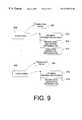
- FIG. 9is a block diagram showing destination determination structures used by session object 316 to determine destinations for incoming information.
- structure pointers 908 and 920are used to access respective incoming information criteria ( 910 and 916 ), and further levels of destination determination information ( 912 , 914 , and 918 ).
- the incoming information criteriasuch as 910 , provides criteria to session object 316 defining how the incoming information, including protocol, data, or both, are to be analyzed.
- Structure pointers 908 and 920also point to translation caches 922 and 924 , respectively.
- Translation caches 922 and 924hold recent resolved destination determinations for the corresponding destination determination structures, and are managed by session objects 316 . These caches may be used by session objects 316 to assist in resolving destinations, and may be used to resolve destinations at any stage in the process of destination determination. For example, if a first destination has been determined using incoming information criteria 910 , this may be checked against translation cache 922 to see if a recent previous same destination has already been analyzed. Caching recently resolved destinations may relieve session object 316 from performing extensive further analysis.
- Structure pointers 908 and 920are representative only.
- the destination structuresmay be accessed by any memory structure accessing method.
- pointerscould be used to reach entity.
- Each level of destination determination structuresmay include data and programs, including algorithms, which are used by session object 316 to determine destinations. These may be as simple as associating a source with a destination, or as complex as an algorithmic scheme.
- incoming information criteria 910defines how specific fields of the Internet protocol are to be analyzed for destination determination, and how the data portion of the Internet information is to be analyzed for destination determination.
- the criteriamight specify that all incoming Internet information having a particular value in a particular field should be sent to a fax machine on telephone network 124 .
- FIG. 9shows second level destination determination criteria, 912 and 918 , and third level destination determination criteria 914 .
- These further levelsare representative of destination determinations beyond simple protocol and data analysis of the incoming information. For example, a further level might require that, with respect to the destinations determined based on incoming criteria 910 , all faxes to destination Y should instead be routed to Internet address X.
- Another example of further level destination determinationis a least cost routing analysis. For example, if the incoming information is determined to be going to a particular destination, session object 316 may analyze the destination to determine which communicative route would be least expensive based on known route cost information. Cost may be in terms of time or other criteria, such as load.
- a structure 908 and 920may be stored locally in PFB 110 , remotely on the network, or portions may be distributed on the PFB 110 and on networks. Furthermore, the structures may exist in whole or in part in the session object 316 .
- Session object 316may obtain destination structures 908 , 920 of FIG. 9 in a variety of ways. First, session object 316 may be given information, such as the structure 908 , in a message object 314 . This pointer defines where to access the destination structures. Secondly, session object 316 may be created already having the destination determination structures, or having information necessary to locate them.
- the destination determination structures stored in, for example, RAM 224define how incoming information protocol and data are to be analyzed to determine destinations.
- the structuresare preferably centralized in PFB 110 , but may be distributed. In the preferred embodiment, they are located in session object 316 , but may be wholly or partially located elsewhere in PFB 110 , or on the networks. Session object 316 preferably accesses the destination structures under direction of information in message objects 314 from source object 312 , but may do so based on information in the session object 316 at the time of creation.
- Destination structuresmay be input or modified in several ways, using the user interface elements such as display 222 ,I/O 218 or interfaces 214 and 216 .
- theymay be input to PFB 110 by a system administrator or user through common interfaces, such as a telephone or a Web browser, or may be changed dynamically by PFB 110 .
- Modification of destination structuresis also object-oriented. In general, PFB 110 creates an object in response to user input, and the object carries out the requests. One or more objects are then used to implement the modifications.
- Destination structuresmay also change dynamically by having further destination level criteria which changes itself according to some monitored condition.
- second level destination determination information 912could be defined to change from one criteria to another based on a certain date.
- associations and analyseswhich may be performed on incoming information is immense. These associations and analyses can be divided into the following criteria categories: protocol, data, time, source, destination, and cost. Although some criteria are related, and may overlap in certain circumstances, an important feature of the invention is that destination structures used by session object 316 may associate virtually any destination with these criteria, or combinations of these criteria. The following discussion provides examples of data and programs/analyses which may be used in the destination structures.
- An example of using data criteria for information processingis for session object 316 to analyze incoming fax information for particular information. If the particular information is found, the fax message is sent to a destination associated with the particular information.
- the particular informationmay be in the body of the fax or on the fax cover page.
- the destination criteria in the destination structuremay specify that incoming information having a data portion smaller than 2000 bytes (2K) should be routed to fax machine X, and anything larger be routed to fax machine Y.
- session object 316buffers up to 2K of data so the determination can be made.
- caller IDis a way of determining the source of a call, which is now a common telephone service.
- destination structuresmay require using caller ID information for destination determination.
- a similar featurecan be implemented on information arriving at PFB 110 via the Internet.
- a network address identifying the Internet sourceis used to determine further destination processing.
- destination structuresmay be defined which send information for one initially specified particular destination to be sent to an entirely different destination.
- PFB 110may also use a form of Direct Inward Dialing (DID).
- DIDDirect Inward Dialing
- Specific phone numbersare assigned to specific individuals, even though all of the numbers ring a single telephone connection at an interface of PFB 110 .
- the actual dialed numberis included with an incoming fax, enabling specific identification of the person to whom the fax should be delivered.
- the use of “pseudo telephone numbers”expands the concept of DID and empowers users to make assignments that are normally only handled by phone companies.
- the session object 316which is created in response to incoming fax information from fax machine 116 may use a destination structure which directs it to convert particular fax destination addresses to E-mail addresses.
- the telephone numberthus has become a pseudo number of an E-mail box.
- each PFBhas a TCP/IP address (a unique identifier assigned to each computer on the Internet), and has a routing table which defines destinations.
- Other PFBsreceive these routing tables for use with their own destination structures in two ways. First, a PFB can query another PFB dynamically. Secondly, a PFB may query a directory system contained in a computer connected to the Internet which stores the routing tables.
- a session object 316 in a New York PFBreceives information from source object 312 , and the associated incoming information criteria 910 in the destination structure directs session object 316 to search the received information for destinations.
- the destination structurefurther specifies that if Paris is found as a destination, session object 316 should find another PFB having the capability of transmitting to Paris.
- the session object 316performs this by searching the routing tables already received by the PFB, by querying other PFBs for their routing tables, or by contacting the directory system (or a combination of these). Session object 316 finds a routing table of a London pFB which specifies that it can reach any telephone in country codes 44 (UK) and 33 (France). The session object 316 creates the appropriate destination object 318 for transmission of the information to the London PFB which transmits to Paris.
- UKcountry codes 44
- FranceFrance
- Destination structurescan also direct session objects 316 to use “directory services” to resolve destination information.
- Directory servicesare computers connected to the Internet, such as name servers or directory servers. The general concept is that a name is sent to a directory service, and an Internet network identification address is returned. Destination structures used by session object 316 may require session object 316 to retrieve a network address using a directory service.
- session object 316may be directed by destination structures to check recent routing information to see if the destination associated with the destination number is known (e.g., from a translation cache 922 ). If not, session object 316 may be directed by destination structures to send out a directory services query. The results of the directory services query, based upon the destination number, is either a destination address or an “I don't know” response. In the latter case, a default action would be carried out by session object 316 and destination object 318 , such as dialing the destination number on a telephone interface.
- session object 316creates a destination object 318 to send a fax to that address.
- the addressis an address on the Internet (e.g., another PFB)
- the faxmay be converted to E-mail format by destination object 318 , and sent over the network connection for arrival at the destination.
- the destinationmay be responsible for additional routing, if necessary.
- session object 316may receive from the service a straight Internet Protocol (IP) address. Based on this address, session object 316 may be directed by the destination structure to merely send the information over to another PFB, and that PFB would be responsible for handling the information. Or, the destination received from the directory service might be a mail server. Session object 316 recognizes that this received information is a mail box address.
- IPInternet Protocol
- destination structuresmay direct session object 316 to analyze the destination number of the incoming message to determine other numbers which can be used to route the information to the appropriate destination. This might include other numbers in a corporation, other PFB numbers, etc.
- a destination structure used by session object 316 to resolve destinationsmay also map dialed telephone numbers to E-mail destinations, or into a list of other numbers, each of which will be resolved into a destination address. In this way, a fax machine user needs to only dial numbers as they normally would to send faxes, E-mail, or combinations of the two.
- destination object 318After final destinations have been determined, information from the source is sent to destination object 318 , which performs the final processing for the destination. Several examples will serve to illustrate the information processing performed by destination objects 318 .
- destination objects 318converts protocol and data of E-mail to faxes. For E-mail containing rich text or embedded objects, this requires destination object 318 to convert from rich text or embedded objects to fax information.
- Outgoing faxesmay be processed by destination objects 318 .
- the outgoing cover pagemay be altered to insert graphic elements, insert routing information in the form of bar codes, fill-in boxes and printable text with alignment cues, perform a specific algorithms for translating PSTN addresses (phone numbers) into Internet or E-mail addresses, and use extra digits to specify routing information which is included in subsequent transmission.
- FIG. 10shows a mailbox system which may optionally reside in PFB 110 .
- Mailbox manager 1008is a software application module which manages mailboxes 1010 , 1012 . . . 1014 .
- the mailboxesmay be stored locally on PFB 110 , or remotely on a network.
- Mailbox manager 1008maintains mailbox location table 1022 to keep track of the location of each mailbox. This is implemented by simply associating a destination identifier with a location of the mailbox.
- Mailbox manager 1008also handles retrieval requests and storing requests for the mailboxes.
- the destination object 318transfers the information to mailbox manager 1008 for storage in the mailbox associated with the destination.
- inbound faxescan be stored in personal mailboxes for retrieval with codes keyed in on the fax machine. That is, when a user begins pressing keys on fax machine 116 , a source object is created, which creates session object 316 . Session object 316 recognizes certain dial tones entered into fax machine 116 as mailbox access tones. In response, session object creates a second source object 312 to retrieve information from mailbox manager 1008 . This sets up the usual cycle of session object creation, destination object creation, and information transfer from the mailbox to the fax machine or other destination as directed by the user.
- Caching of received faxesalso allows a user to retrieve and view faxes over the Internet, or to reroute them as E-mail.
- Another exampleillustrates how faxes in a corporate structure may be redirected several times based on destination, perhaps a company sends a lot of faxes to Brazil. Outgoing faxes are routed to the PFB at the company's Miami location. This routing is performed by session object 316 , in accordance with the destination structures, directing all faxes with the Brazil country code in the destination number to the Miami PFB.
- the Miami PFBhas destination determination structures which require, for example, that if certain fax numbers require that, MCI mail should be used and the fax is delivered as text to MCI mail. Destination numbers of other messages result in the message being routed in the normal manner over the telephone network.
- PFB 110can also operate in a direct mode over a communications path, such as the Internet. Instead of using E-mail transport, a direct connection between two PFB-equipped fax machines takes place over the Internet or other network.
- the session object 316created at the first PFB in response to the incoming fax, creates a destination object 318 , which translates the incoming fax information to an Internet protocol, and transmits the fax information over the Internet to a second PFB.
- a session object 316 at the receiving endcreated by a source object 312 in response to the incoming information, creates a destination object 318 , which converts the fax information from the Internet protocol back to fax protocol, and sends the fax information to the fax machine at the second pFB.
- This processincludes converting fax scan line information to a format compatible with the network protocol requirements, which may require dividing the fax scan line information into segments.
- session object 316buffers the information and reconverts it back to scan line fax information.
- a companymay have several PFBs for its US offices.
- a PFB in Los Angelesmay be set up to accepts all fax traffic for area codes 818, 213, 310, 714, 805, and 909.
- a PFB in New Yorkaccepts fax traffic for area codes 212, 201, 506, and 914.
- destination object 318implements a point-to-point protocol (PPP).
- PPPis a well-known data link protocol utilizing multiprotocol framing for transferring information.
- PPPalso uses a link control protocol for establishing and releasing connections.
- NCPnetwork control protocol
- PPPallows a user to place a telephone call to an Internet service provider (ISP) to establish a home pC connection through a temporary host.
- ISPInternet service provider
- the home PCcalls the ISP over the telephone lines, and performs some initializing to set up the parameters of the protocol for the connection. Then the home PC receives a temporary Ip address. Using this IP address, the home PC can send and receive IP packets, basically acting just like a host. Once the necessary transfers have been made, the connection is released.
- ISPInternet service provider
- FIG. 11is a flowchart showing processing performed by a PPP destination object to carry out PPP transfers in accordance with a preferred embodiment of the present invention.
- session object 316Prior to destination object being created, session object 316 has established that an incoming fax or e-mail has a destination which requires a particular PPP destination object 318 .
- PPP destination object 318receives from session object 316 the dial out number required to establish the PPP connection. Alternatively, PPP object 318 may already have the necessary PPP dial out number necessary for the connection set up. In either case, PPP object 318 dials out over a standard “plain old telephone system” (POTS) port (step 1110 ) and establishes the PPP connection (step 1112 ).
- POTSplain old telephone system
- PPP destination object 318transmits information received from session object 316 over the established link to the appropriate destination until all information has been transferred (step 1114 ). As discussed above, the information is transferred in the appropriate format, translated if necessary, by PPP destination object 318 to interface 320 and the destination. PPP destination object 318 then closes down the PPP connection (step 1116 ), and notifies session object 316 that operations are finished (step 1118 ).
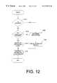
- FIG. 12is a flow chart showing processing of a preferred embodiment which handles incoming IP addresses using PPP connections.
- interfaces 310 and 320may be Ethernet ports.
- PFB 110is connected to both an Ethernet and to one or more computers, via direct or network connections. Initially, PFB 110 receives information over interface 310 , creates an appropriate source object 312 and session object 316 . If session object 316 receives an IP destination address from the Ethernet or computer (step 1210 ), session object 316 determines whether the IP address requires a PPP connection (step 1212 ).
- the IP addressmay be compared against known Ip addresses which require ppp connections.
- the IP addressmay be checked against known IP addresses not requiring a PPP connection, and if the IP address is not found, it is assumed a PPP connection is required. If a PPP connection is required, a PPP destination object 318 is created, and the procedures outlined above with respect to FIG. 11 are followed (step 1214 ). If the incoming information is not an IP address (step 1210 ), then destinations must be determined (step 1222 ), and destination objects must be created (step 1226 ).
- FIG. 13is a block diagram showing a system using a PFB in accordance with a preferred embodiment of the invention.
- a PFB 110is connected to various entities, such as computer 1326 , computer network 122 , telephone network 124 , and fax machine 116 , similar to the system of FIG. 1 .
- the embodiment of FIG. 13also includes an Ethernet hub 1318 , which is connected to several Ethernet devices 1314 , 1310 , and 1320 .
- Ethernet hub 1318is also connected to PFB 110 .
- Ethernet hub 1318routes all incoming traffic to the other remaining devices connected to the hub, as is commonly understood in the art.
- Ethernet devices 1314 , 1310 and 1320may all take advantage of the features of PFB 110 , as described above.
- a preferred embodimentincludes Ethernet hub 1318 and PFB 110 in a single device 1342 .
- This configurationpermits a user to implement a network using a variety of Ethernet and non-Ethernet devices connected to a single network box, thereby enabling a variety of protocol conversions and destination routing using an Ethernet hub architecture. This provides a plug-and-play local area network without requiring servers.
- FIG. 14is a flow chart showing processing in another embodiment where PFB 110 receives notifications of e-mail and, in response, sets up a PPP connection to retrieve the e-mail.
- an agentmonitors an e-mail server on the network for incoming e-mail.
- an “agent”is a part of a networked system which performs information preparation and exchange on behalf of a software or hardware entity.
- the agentUpon receiving an indication that e-mail has arrived, the agent calls PFB 110 .
- PFB 110creates source object 312 (step 1410 ) which creates session object 316 (step 1414 ).
- Session object 316determines that the incoming call is from the agent (step 1418 ). This determination may be made in several ways. For example, session object 316 may check caller ID and identify the call source as the agent. Alternatively, the agent may hang up after one ring, which is also detected by session object 316 .
- processingproceeds to determine destinations (step 1422 ). This is followed by creation of the appropriate destination objects to carry out the transfer (step 1428 ).
- Session object 316responds by creating an e-mail retrieval PPP object (step 1424 ), which sets up the PPP connection and retrieves the e-mail.
- This objectis similar to the PPP destination object 318 described in the previous scenarios, but instead retrieves information rather than transmits it.
- the e-mail retrieval PPP objectis also similar to source object 312 (receiving information coming to the PFB), with the exception that the PPP destination object 318 initiates the connection, and the link to session object 316 is already established.
- session object 316begins handling the e-mail as it would if the e-mail had arrived coming into PFB 110 unsolicited. That is, session object determines the destination of the e-mail, and sets up the necessary destination objects 318 for transfer (step 1428 ). The e-mail is then transferred (step 1432 ). Alternatively, the PPP connection may remain open until a period of time has elapsed without the arrival of additional e-mails, or until a predetermined period of time has elapsed.
- the present inventionthus provides apparatus and methods for increasing efficiency and convenience of exchanging information in a corporate environment over a multitude of information formats and transfer channels. It will be apparent to those skilled in the art that various modifications and variations can be made in the preferred embodiment of the present invention and in construction of this protocol Fax Box without departing from the scope or spirit of the invention.
Landscapes
- Engineering & Computer Science (AREA)
- Signal Processing (AREA)
- Multimedia (AREA)
- Computer Networks & Wireless Communication (AREA)
- General Engineering & Computer Science (AREA)
- Computing Systems (AREA)
- Facsimiles In General (AREA)
Abstract
Description
Claims (28)
Priority Applications (4)
| Application Number | Priority Date | Filing Date | Title |
|---|---|---|---|
| US08/770,775US6278532B1 (en) | 1996-12-20 | 1996-12-20 | Apparatus and method for reception and transmission of information using different protocols |
| AU59006/98AAU5900698A (en) | 1996-12-20 | 1997-12-19 | Apparatus and methods for reception and transmission of information using different protocols |
| PCT/US1997/023554WO1998028892A1 (en) | 1996-12-20 | 1997-12-19 | Apparatus and methods for reception and transmission of information using different protocols |
| EP97954593AEP1010309A1 (en) | 1996-12-20 | 1997-12-19 | Apparatus and methods for reception and transmission of information using different protocols |
Applications Claiming Priority (1)
| Application Number | Priority Date | Filing Date | Title |
|---|---|---|---|
| US08/770,775US6278532B1 (en) | 1996-12-20 | 1996-12-20 | Apparatus and method for reception and transmission of information using different protocols |
Publications (1)
| Publication Number | Publication Date |
|---|---|
| US6278532B1true US6278532B1 (en) | 2001-08-21 |
Family
ID=25089639
Family Applications (1)
| Application Number | Title | Priority Date | Filing Date |
|---|---|---|---|
| US08/770,775Expired - LifetimeUS6278532B1 (en) | 1996-12-20 | 1996-12-20 | Apparatus and method for reception and transmission of information using different protocols |
Country Status (4)
| Country | Link |
|---|---|
| US (1) | US6278532B1 (en) |
| EP (1) | EP1010309A1 (en) |
| AU (1) | AU5900698A (en) |
| WO (1) | WO1998028892A1 (en) |
Cited By (50)
| Publication number | Priority date | Publication date | Assignee | Title |
|---|---|---|---|---|
| US20020042751A1 (en)* | 2000-07-06 | 2002-04-11 | Anthony Sarno | Systems and methods for business to business financial analysis |
| US6411685B1 (en)* | 1999-01-29 | 2002-06-25 | Microsoft Corporation | System and method for providing unified messaging to a user with a thin web browser |
| US20020191574A1 (en)* | 2001-06-04 | 2002-12-19 | Rebecca S. Taylor | Dynamically extensible communications gateway |
| US6651109B1 (en) | 1997-03-31 | 2003-11-18 | Intel Corporation | Inter-object messaging |
| US6671706B1 (en)* | 2000-08-12 | 2003-12-30 | Keith Vinh | Method and system for editing the content of a web site with a facsimile transmission |
| US6681274B2 (en) | 2001-10-15 | 2004-01-20 | Advanced Micro Devices, Inc. | Virtual channel buffer bypass for an I/O node of a computer system |
| US6697890B1 (en) | 2001-12-27 | 2004-02-24 | Advanced Micro Devices, Inc. | I/O node for a computer system including an integrated I/O interface |
| US6721816B1 (en) | 2002-02-27 | 2004-04-13 | Advanced Micro Devices, Inc. | Selecting independently of tag values a given command belonging to a second virtual channel and having a flag set among commands belonging to a posted virtual and the second virtual channels |
| US6725297B1 (en) | 2001-10-15 | 2004-04-20 | Advanced Micro Devices, Inc. | Peripheral interface circuit for an I/O node of a computer system |
| US6728790B2 (en) | 2001-10-15 | 2004-04-27 | Advanced Micro Devices, Inc. | Tagging and arbitration mechanism in an input/output node of a computer system |
| US6748054B1 (en) | 1997-09-08 | 2004-06-08 | Worldcom, Inc. | Single telephone number access to multiple communications services |
| US6757755B2 (en) | 2001-10-15 | 2004-06-29 | Advanced Micro Devices, Inc. | Peripheral interface circuit for handling graphics responses in an I/O node of a computer system |
| US6785730B1 (en) | 1999-02-16 | 2004-08-31 | Rebecca S. Taylor | Generic communications protocol translator |
| US20040172493A1 (en)* | 2001-10-15 | 2004-09-02 | Advanced Micro Devices, Inc. | Method and apparatus for handling split response transactions within a peripheral interface of an I/O node of a computer system |
| US6791554B1 (en) | 2001-12-27 | 2004-09-14 | Advanced Micro Devices, Inc. | I/O node for a computer system including an integrated graphics engine |
| US6807599B2 (en) | 2001-10-15 | 2004-10-19 | Advanced Micro Devices, Inc. | Computer system I/O node for connection serially in a chain to a host |
| US6820151B2 (en) | 2001-10-15 | 2004-11-16 | Advanced Micro Devices, Inc. | Starvation avoidance mechanism for an I/O node of a computer system |
| US6834319B1 (en) | 2002-03-21 | 2004-12-21 | Advanced Micro Devices, Inc. | Tunnel device for an input/output node of a computer system |
| US6839784B1 (en) | 2001-10-15 | 2005-01-04 | Advanced Micro Devices, Inc. | Control unit of an I/O node for a computer system including a plurality of scheduler units each including a plurality of buffers each corresponding to a respective virtual channel |
| US6857033B1 (en) | 2001-12-27 | 2005-02-15 | Advanced Micro Devices, Inc. | I/O node for a computer system including an integrated graphics engine and an integrated I/O hub |
| US20050086348A1 (en)* | 1999-12-29 | 2005-04-21 | Edward Balassanian | Method and system for data demultiplexing |
| US6892239B1 (en) | 2000-03-23 | 2005-05-10 | International Business Machines Corporation | Method, system, and program for transmitting facsimiles in a network environment |
| US6914693B1 (en)* | 2000-03-23 | 2005-07-05 | International Business Machines Corporation | Method, system, and program for transmitting facsimiles in a network environment where multiple fax servers use a common rendering machine |
| US6968417B1 (en) | 2002-03-21 | 2005-11-22 | Advanced Micro Devices, Inc. | Method and apparatus for reducing latency in a peripheral interface circuit of an I/O node of a computer system |
| US6985935B1 (en)* | 2000-12-20 | 2006-01-10 | Cisco Technology, Inc. | Method and system for providing network access to PPP clients |
| US6985576B1 (en)* | 1999-12-02 | 2006-01-10 | Worldcom, Inc. | Method and apparatus for automatic call distribution |
| US6996657B1 (en) | 2002-03-21 | 2006-02-07 | Advanced Micro Devices, Inc. | Apparatus for providing packets in a peripheral interface circuit of an I/O node of a computer system |
| US7007061B1 (en)* | 2000-08-07 | 2006-02-28 | Cisco Technology, Inc. | Communicating data using facsimile protocols |
| US7088801B1 (en) | 1997-09-08 | 2006-08-08 | Mci, Inc. | Single telephone number access to multiple communications services |
| US20060278155A1 (en)* | 2003-07-23 | 2006-12-14 | Bernd Soltendieck | Display device for a motor vehicle |
| US20070030843A1 (en)* | 2001-10-19 | 2007-02-08 | Miller Frank W | Voice over IP architecture |
| US20070078929A1 (en)* | 2005-09-30 | 2007-04-05 | Bigfoot Networks, Inc. | Distributed processing system and method |
| US20070076829A1 (en)* | 2005-10-05 | 2007-04-05 | Lg Electronics Inc. | Digital television transmitter and method of coding data in digital television transmitter |
| US20070081457A1 (en)* | 1995-04-28 | 2007-04-12 | J2 Global Communications, Inc. | Systems and method for storing, delivering, and managing messages |
| US20070223054A1 (en)* | 1997-10-27 | 2007-09-27 | Canon Kabushiki Kaisha | Data communication apparatus and method |
| US20070263258A1 (en)* | 2006-05-10 | 2007-11-15 | Fuji Xerox Co., Ltd. | Image transmitting apparatus, image receiving apparatus, and image transmitting and receiving apparatus and system |
| US7380007B1 (en)* | 2000-06-30 | 2008-05-27 | Aol Llc, A Delaware Limited Liability Company | Automatic user session |
| US20080159277A1 (en)* | 2006-12-15 | 2008-07-03 | Brocade Communications Systems, Inc. | Ethernet over fibre channel |
| US20080159260A1 (en)* | 2006-12-15 | 2008-07-03 | Brocade Communications Systems, Inc. | Fibre channel over ethernet frame |
| US20080181243A1 (en)* | 2006-12-15 | 2008-07-31 | Brocade Communications Systems, Inc. | Ethernet forwarding in high performance fabrics |
| CN100442812C (en)* | 2005-06-29 | 2008-12-10 | 株式会社东芝 | Image forming device and facsimile data transmission method of image forming device |
| US20090132701A1 (en)* | 2007-11-20 | 2009-05-21 | Robert Snively | Duplicate address discovery and action |
| US20090292813A1 (en)* | 2007-12-17 | 2009-11-26 | Brocade Communications Systems, Inc. | Address Assignment in Fibre Channel Over Ethernet Environments |
| US20090296726A1 (en)* | 2008-06-03 | 2009-12-03 | Brocade Communications Systems, Inc. | ACCESS CONTROL LIST MANAGEMENT IN AN FCoE ENVIRONMENT |
| US20100128298A1 (en)* | 2008-11-27 | 2010-05-27 | Canon Kabushiki Kaisha | Image forming apparatus, log recording method, and program |
| US7769001B2 (en) | 1998-06-12 | 2010-08-03 | J2 Global Communications, Inc. | Scalable architecture for transmission of messages over a network |
| US8848575B2 (en) | 2009-02-23 | 2014-09-30 | Brocade Communications Systems, Inc. | High availability and multipathing for fibre channel over ethernet |
| CN105207885A (en)* | 2015-07-07 | 2015-12-30 | 广州华多网络科技有限公司 | Method and device for displaying user information in session interface |
| US9426207B2 (en) | 2005-05-11 | 2016-08-23 | Qualcomm Incorporated | Distributed processing system and method |
| US10887475B2 (en)* | 2018-12-07 | 2021-01-05 | Kyocera Document Solutions Inc. | Communication apparatus and control method therefor |
Families Citing this family (7)
| Publication number | Priority date | Publication date | Assignee | Title |
|---|---|---|---|---|
| JP3147064B2 (en)* | 1997-11-18 | 2001-03-19 | ブラザー工業株式会社 | Facsimile machine and storage medium |
| DE69927454T2 (en) | 1998-04-06 | 2006-03-23 | Panasonic Communications Co., Ltd. | IMAGE COMMUNICATION DEVICE AND METHOD |
| EP0975145B1 (en)* | 1998-07-22 | 2008-07-30 | Canon Kabushiki Kaisha | Information processing system and information processing method |
| JP3135532B2 (en)* | 1998-09-29 | 2001-02-19 | 松下電送システム株式会社 | Network facsimile machine |
| JP4668422B2 (en)* | 1999-02-16 | 2011-04-13 | ルーベック カンポヴェッロ, リミテッド ライアビリティ カンパニー | General-purpose communication protocol converter |
| JP2001203849A (en) | 2000-01-20 | 2001-07-27 | Canon Inc | Communication method and communication device |
| US7010635B1 (en)* | 2000-03-21 | 2006-03-07 | Ricoh Co., Ltd | Method and apparatus for using a person digital assistant to interface with a communication station |
Citations (22)
| Publication number | Priority date | Publication date | Assignee | Title |
|---|---|---|---|---|
| US4922348A (en) | 1989-02-10 | 1990-05-01 | American Telephone And Telegraph Company | Facsimile service |
| US4994926A (en) | 1988-09-22 | 1991-02-19 | F-Mail Associates, L.P. | Facsimile telecommunications system and method |
| US5091790A (en) | 1989-12-29 | 1992-02-25 | Morton Silverberg | Multipurpose computer accessory for facilitating facsimile communication |
| US5115326A (en) | 1990-06-26 | 1992-05-19 | Hewlett Packard Company | Method of encoding an e-mail address in a fax message and routing the fax message to a destination on a network |
| US5127048A (en) | 1990-05-11 | 1992-06-30 | Fisk Communications, Inc. | Free standing data transfer device for coupling a facsimile machine to a telephone line |
| EP0504884A2 (en) | 1991-03-19 | 1992-09-23 | Fujitsu Limited | Facsimile mail system linked to data communication system |
| US5287199A (en) | 1992-02-27 | 1994-02-15 | At&T Bell Laboratories | Facsimile message processing and routing system |
| US5305401A (en)* | 1990-12-21 | 1994-04-19 | Thomson-Csf | Optical connection device and data processing apparatus fitted with optical transmission means |
| US5339174A (en) | 1989-05-02 | 1994-08-16 | Harris Scott C | Facsimile machine time shifting and converting apparatus |
| US5404231A (en) | 1993-05-24 | 1995-04-04 | Audiofax, Inc. | Sender-based facsimile store and forward facility |
| EP0666670A2 (en) | 1993-12-30 | 1995-08-09 | International Business Machines Corporation | General transport layer gateway for heterogeneous networks |
| WO1995022865A1 (en) | 1994-02-18 | 1995-08-24 | Microsoft Corporation | A system for transferring messages between input and output devices in a communication device |
| US5452106A (en) | 1992-05-27 | 1995-09-19 | Exfax Technologies Ltd Pty | Modem device for communication of facsimile or file data |
| US5459584A (en) | 1988-09-22 | 1995-10-17 | Audiofax, Inc. | Facsimile telecommunications system and method |
| US5461488A (en) | 1994-09-12 | 1995-10-24 | Motorola, Inc. | Computerized facsimile (FAX) system and method of operation |
| US5479411A (en)* | 1993-03-10 | 1995-12-26 | At&T Corp. | Multi-media integrated message arrangement |
| US5555100A (en) | 1993-10-07 | 1996-09-10 | Audiofax, Inc. | Facsimile store and forward system with local interface translating DTMF signals into store and forward system commands |
| US5696600A (en) | 1992-05-27 | 1997-12-09 | Exfax Technologies Pty Ltd | Modem device for use with a facsimile machine combined with a PC |
| US5758159A (en)* | 1991-07-16 | 1998-05-26 | Alcatel N.V. | Structured software for a telecommunication system, including a communication service object which uses relationship data to route a message from an originator object to a recipient object |
| US5850449A (en)* | 1995-10-26 | 1998-12-15 | Sun Microsystems, Inc. | Secure network protocol system and method |
| US5983259A (en)* | 1997-02-19 | 1999-11-09 | International Business Machines Corp. | Systems and methods for transmitting and receiving data in connection with a communications stack in a communications system |
| US6182154B1 (en)* | 1994-11-21 | 2001-01-30 | International Business Machines Corporation | Universal object request broker encapsulater |
Family Cites Families (1)
| Publication number | Priority date | Publication date | Assignee | Title |
|---|---|---|---|---|
| US4902881A (en)* | 1988-06-10 | 1990-02-20 | Faxplus Corporation | Parallel process communications terminal and network |
- 1996
- 1996-12-20USUS08/770,775patent/US6278532B1/ennot_activeExpired - Lifetime
- 1997
- 1997-12-19EPEP97954593Apatent/EP1010309A1/ennot_activeWithdrawn
- 1997-12-19WOPCT/US1997/023554patent/WO1998028892A1/ennot_activeApplication Discontinuation
- 1997-12-19AUAU59006/98Apatent/AU5900698A/ennot_activeAbandoned
Patent Citations (28)
| Publication number | Priority date | Publication date | Assignee | Title |
|---|---|---|---|---|
| US4994926A (en) | 1988-09-22 | 1991-02-19 | F-Mail Associates, L.P. | Facsimile telecommunications system and method |
| US5459584A (en) | 1988-09-22 | 1995-10-17 | Audiofax, Inc. | Facsimile telecommunications system and method |
| US4994926B1 (en) | 1988-09-22 | 1998-08-18 | Audiofax Ip L L C | Fascimilie telecommunications system and method |
| US5291302A (en) | 1988-09-22 | 1994-03-01 | Audiofax, Inc. | Facsimile telecommunications system and method |
| US4994926C1 (en) | 1988-09-22 | 2001-07-03 | Audiofax Ip L L C | Facsimile telecommunications system and method |
| US4922348B1 (en) | 1989-02-10 | 1994-10-11 | Bell Telephone Labor Inc | Facsimile service |
| US4922348A (en) | 1989-02-10 | 1990-05-01 | American Telephone And Telegraph Company | Facsimile service |
| US5339174A (en) | 1989-05-02 | 1994-08-16 | Harris Scott C | Facsimile machine time shifting and converting apparatus |
| US5091790A (en) | 1989-12-29 | 1992-02-25 | Morton Silverberg | Multipurpose computer accessory for facilitating facsimile communication |
| US5127048A (en) | 1990-05-11 | 1992-06-30 | Fisk Communications, Inc. | Free standing data transfer device for coupling a facsimile machine to a telephone line |
| US5115326A (en) | 1990-06-26 | 1992-05-19 | Hewlett Packard Company | Method of encoding an e-mail address in a fax message and routing the fax message to a destination on a network |
| US5305401A (en)* | 1990-12-21 | 1994-04-19 | Thomson-Csf | Optical connection device and data processing apparatus fitted with optical transmission means |
| EP0504884A2 (en) | 1991-03-19 | 1992-09-23 | Fujitsu Limited | Facsimile mail system linked to data communication system |
| US5758159A (en)* | 1991-07-16 | 1998-05-26 | Alcatel N.V. | Structured software for a telecommunication system, including a communication service object which uses relationship data to route a message from an originator object to a recipient object |
| US5287199A (en) | 1992-02-27 | 1994-02-15 | At&T Bell Laboratories | Facsimile message processing and routing system |
| US5452106A (en) | 1992-05-27 | 1995-09-19 | Exfax Technologies Ltd Pty | Modem device for communication of facsimile or file data |
| US5696600A (en) | 1992-05-27 | 1997-12-09 | Exfax Technologies Pty Ltd | Modem device for use with a facsimile machine combined with a PC |
| US5479411A (en)* | 1993-03-10 | 1995-12-26 | At&T Corp. | Multi-media integrated message arrangement |
| US5404231A (en) | 1993-05-24 | 1995-04-04 | Audiofax, Inc. | Sender-based facsimile store and forward facility |
| US5555100A (en) | 1993-10-07 | 1996-09-10 | Audiofax, Inc. | Facsimile store and forward system with local interface translating DTMF signals into store and forward system commands |
| US5559611A (en) | 1993-10-07 | 1996-09-24 | Audiofax, Inc. | Facsimile store and forward system with local interface |
| EP0666670A2 (en) | 1993-12-30 | 1995-08-09 | International Business Machines Corporation | General transport layer gateway for heterogeneous networks |
| US5499109A (en) | 1994-02-18 | 1996-03-12 | Microsoft Corporation | System for transferring messages between input and output devices in a communication device |
| WO1995022865A1 (en) | 1994-02-18 | 1995-08-24 | Microsoft Corporation | A system for transferring messages between input and output devices in a communication device |
| US5461488A (en) | 1994-09-12 | 1995-10-24 | Motorola, Inc. | Computerized facsimile (FAX) system and method of operation |
| US6182154B1 (en)* | 1994-11-21 | 2001-01-30 | International Business Machines Corporation | Universal object request broker encapsulater |
| US5850449A (en)* | 1995-10-26 | 1998-12-15 | Sun Microsystems, Inc. | Secure network protocol system and method |
| US5983259A (en)* | 1997-02-19 | 1999-11-09 | International Business Machines Corp. | Systems and methods for transmitting and receiving data in connection with a communications stack in a communications system |
Non-Patent Citations (1)
| Title |
|---|
| C++ in Plain English; Brian Overland pp. v, 134-35; 350-55, 1996.* |
Cited By (90)
| Publication number | Priority date | Publication date | Assignee | Title |
|---|---|---|---|---|
| US7895313B2 (en) | 1994-05-13 | 2011-02-22 | Advanced Messaging Technologies, Inc. | Systems and methods for storing, delivering, and managing messages |
| US20070081457A1 (en)* | 1995-04-28 | 2007-04-12 | J2 Global Communications, Inc. | Systems and method for storing, delivering, and managing messages |
| US7836141B2 (en) | 1995-04-28 | 2010-11-16 | Advanced Messaging Technologies, Inc. | Systems and method for storing, delivering, and managing messages |
| US7895306B2 (en) | 1995-04-28 | 2011-02-22 | Advanced Messaging Technologies, Inc. | Systems and methods for storing, delivering, and managing messages |
| US7934148B2 (en) | 1995-04-28 | 2011-04-26 | Advanced Messaging Technologies, Inc. | Systems and method for storing, delivering, and managing messages |
| US6742050B1 (en) | 1997-03-31 | 2004-05-25 | Intel Corporation | Inter-object messaging |
| US7055153B2 (en) | 1997-03-31 | 2006-05-30 | Intel Corporation | Inter-object messaging |
| US6651109B1 (en) | 1997-03-31 | 2003-11-18 | Intel Corporation | Inter-object messaging |
| US6748054B1 (en) | 1997-09-08 | 2004-06-08 | Worldcom, Inc. | Single telephone number access to multiple communications services |
| US6792084B1 (en) | 1997-09-08 | 2004-09-14 | Mci, Inc. | Single telephone number access to multiple communications services |
| US6870909B2 (en) | 1997-09-08 | 2005-03-22 | Mci, Inc. | Single telephone number access to multiple communications services |
| US7831029B2 (en) | 1997-09-08 | 2010-11-09 | Gross Karen A | Single telephone number access to multiple communications services |
| US7088801B1 (en) | 1997-09-08 | 2006-08-08 | Mci, Inc. | Single telephone number access to multiple communications services |
| US7573995B2 (en) | 1997-09-08 | 2009-08-11 | Verizon Business Global Llc | Single telephone number access to multiple communications services |
| US6795532B1 (en) | 1997-09-08 | 2004-09-21 | Mci, Inc. | Single telephone number access to multiple communication services |
| US8175245B2 (en) | 1997-09-08 | 2012-05-08 | Yolab Networks, L.L.C. | Single telephone number access to multiple communications services |
| US20110002011A1 (en)* | 1997-10-27 | 2011-01-06 | Canon Kabushiki Kaisha | Data communication apparatus and method |
| US8164779B2 (en) | 1997-10-27 | 2012-04-24 | Canon Kabushiki Kaisha | Data communication apparatus and method |
| US8395800B2 (en) | 1997-10-27 | 2013-03-12 | Canon Kabushiki Kaisha | Data communication apparatus and method |
| US20070223054A1 (en)* | 1997-10-27 | 2007-09-27 | Canon Kabushiki Kaisha | Data communication apparatus and method |
| US7839529B2 (en)* | 1997-10-27 | 2010-11-23 | Canon Kabushiki Kaisha | Data communication apparatus and method |
| US8619308B2 (en) | 1997-10-27 | 2013-12-31 | Canon Kabushiki Kaisha | Data communication apparatus and method transmitting input data in parallel to destinations using different transmission protocols |
| US7769001B2 (en) | 1998-06-12 | 2010-08-03 | J2 Global Communications, Inc. | Scalable architecture for transmission of messages over a network |
| US8249062B1 (en) | 1998-06-12 | 2012-08-21 | J2 Global Communications, Inc. | Scalable architecture for transmission of messages over a network |
| US6411685B1 (en)* | 1999-01-29 | 2002-06-25 | Microsoft Corporation | System and method for providing unified messaging to a user with a thin web browser |
| US20110004694A1 (en)* | 1999-02-16 | 2011-01-06 | Taylor Rebecca S | Generic communications protocol translator |
| US20050005022A1 (en)* | 1999-02-16 | 2005-01-06 | Taylor Rebecca S. | Generic Communications Protocol Translator |
| US8341281B2 (en) | 1999-02-16 | 2012-12-25 | Lubec Campobello Llc | Generic communications protocol translator |
| US6785730B1 (en) | 1999-02-16 | 2004-08-31 | Rebecca S. Taylor | Generic communications protocol translator |
| US7792981B2 (en)* | 1999-02-16 | 2010-09-07 | Taylor Rebecca S | Generic communications protocol translator |
| US6985576B1 (en)* | 1999-12-02 | 2006-01-10 | Worldcom, Inc. | Method and apparatus for automatic call distribution |
| US8055786B2 (en)* | 1999-12-29 | 2011-11-08 | Edward Balassanian | Method and system for data demultiplexing |
| US10225378B2 (en) | 1999-12-29 | 2019-03-05 | Implicit, Llc | Method and system for data demultiplexing |
| US9591104B2 (en) | 1999-12-29 | 2017-03-07 | Implicit, Llc | Method and system for data demultiplexing |
| US10027780B2 (en) | 1999-12-29 | 2018-07-17 | Implicit, Llc | Method and system for data demultiplexing |
| US20050086348A1 (en)* | 1999-12-29 | 2005-04-21 | Edward Balassanian | Method and system for data demultiplexing |
| US10033839B2 (en) | 1999-12-29 | 2018-07-24 | Implicit, Llc | Method and system for data demultiplexing |
| US6914693B1 (en)* | 2000-03-23 | 2005-07-05 | International Business Machines Corporation | Method, system, and program for transmitting facsimiles in a network environment where multiple fax servers use a common rendering machine |
| US6892239B1 (en) | 2000-03-23 | 2005-05-10 | International Business Machines Corporation | Method, system, and program for transmitting facsimiles in a network environment |
| US7380007B1 (en)* | 2000-06-30 | 2008-05-27 | Aol Llc, A Delaware Limited Liability Company | Automatic user session |
| US20020042751A1 (en)* | 2000-07-06 | 2002-04-11 | Anthony Sarno | Systems and methods for business to business financial analysis |
| US7007061B1 (en)* | 2000-08-07 | 2006-02-28 | Cisco Technology, Inc. | Communicating data using facsimile protocols |
| US6671706B1 (en)* | 2000-08-12 | 2003-12-30 | Keith Vinh | Method and system for editing the content of a web site with a facsimile transmission |
| US6985935B1 (en)* | 2000-12-20 | 2006-01-10 | Cisco Technology, Inc. | Method and system for providing network access to PPP clients |
| US7668144B2 (en) | 2001-06-04 | 2010-02-23 | Taylor Rebecca S | Dynamically extensible communications device |
| US20020191574A1 (en)* | 2001-06-04 | 2002-12-19 | Rebecca S. Taylor | Dynamically extensible communications gateway |
| US6823405B1 (en) | 2001-10-15 | 2004-11-23 | Advanced Mirco Devices, Inc. | Method and apparatus for initiating partial transactions in a peripheral interface circuit for an I/O node of a computer system |
| US6760792B1 (en) | 2001-10-15 | 2004-07-06 | Advanced Micro Devices, Inc. | Buffer circuit for rotating outstanding transactions |
| US6681274B2 (en) | 2001-10-15 | 2004-01-20 | Advanced Micro Devices, Inc. | Virtual channel buffer bypass for an I/O node of a computer system |
| US6883045B1 (en) | 2001-10-15 | 2005-04-19 | Advanced Micro Devices, Inc. | Apparatus for reordering graphics responses in a peripheral interface circuit for an I/O node of a computer system |
| US6834314B1 (en) | 2001-10-15 | 2004-12-21 | Advanced Micro Devices, Inc. | Method and apparatus for reordering packet transactions within a peripheral interface circuit |
| US6725297B1 (en) | 2001-10-15 | 2004-04-20 | Advanced Micro Devices, Inc. | Peripheral interface circuit for an I/O node of a computer system |
| US6728790B2 (en) | 2001-10-15 | 2004-04-27 | Advanced Micro Devices, Inc. | Tagging and arbitration mechanism in an input/output node of a computer system |
| US6757755B2 (en) | 2001-10-15 | 2004-06-29 | Advanced Micro Devices, Inc. | Peripheral interface circuit for handling graphics responses in an I/O node of a computer system |
| US6760791B1 (en) | 2001-10-15 | 2004-07-06 | Advanced Micro Devices, Inc. | Buffer circuit for a peripheral interface circuit in an I/O node of a computer system |
| US6839784B1 (en) | 2001-10-15 | 2005-01-04 | Advanced Micro Devices, Inc. | Control unit of an I/O node for a computer system including a plurality of scheduler units each including a plurality of buffers each corresponding to a respective virtual channel |
| US20040172493A1 (en)* | 2001-10-15 | 2004-09-02 | Advanced Micro Devices, Inc. | Method and apparatus for handling split response transactions within a peripheral interface of an I/O node of a computer system |
| US6820151B2 (en) | 2001-10-15 | 2004-11-16 | Advanced Micro Devices, Inc. | Starvation avoidance mechanism for an I/O node of a computer system |
| US6807599B2 (en) | 2001-10-15 | 2004-10-19 | Advanced Micro Devices, Inc. | Computer system I/O node for connection serially in a chain to a host |
| US8040877B2 (en) | 2001-10-19 | 2011-10-18 | Foundry Networks, Llc | Voice over IP architecture |
| US20070030843A1 (en)* | 2001-10-19 | 2007-02-08 | Miller Frank W | Voice over IP architecture |
| US6791554B1 (en) | 2001-12-27 | 2004-09-14 | Advanced Micro Devices, Inc. | I/O node for a computer system including an integrated graphics engine |
| US6697890B1 (en) | 2001-12-27 | 2004-02-24 | Advanced Micro Devices, Inc. | I/O node for a computer system including an integrated I/O interface |
| US6857033B1 (en) | 2001-12-27 | 2005-02-15 | Advanced Micro Devices, Inc. | I/O node for a computer system including an integrated graphics engine and an integrated I/O hub |
| US6721816B1 (en) | 2002-02-27 | 2004-04-13 | Advanced Micro Devices, Inc. | Selecting independently of tag values a given command belonging to a second virtual channel and having a flag set among commands belonging to a posted virtual and the second virtual channels |
| US6834319B1 (en) | 2002-03-21 | 2004-12-21 | Advanced Micro Devices, Inc. | Tunnel device for an input/output node of a computer system |
| US6968417B1 (en) | 2002-03-21 | 2005-11-22 | Advanced Micro Devices, Inc. | Method and apparatus for reducing latency in a peripheral interface circuit of an I/O node of a computer system |
| US6996657B1 (en) | 2002-03-21 | 2006-02-07 | Advanced Micro Devices, Inc. | Apparatus for providing packets in a peripheral interface circuit of an I/O node of a computer system |
| US6915371B1 (en)* | 2002-03-21 | 2005-07-05 | Advanced Micro Devices, Inc. | Tunnel device for an input/output node of a computer system |
| US20060278155A1 (en)* | 2003-07-23 | 2006-12-14 | Bernd Soltendieck | Display device for a motor vehicle |
| US9426207B2 (en) | 2005-05-11 | 2016-08-23 | Qualcomm Incorporated | Distributed processing system and method |
| CN100442812C (en)* | 2005-06-29 | 2008-12-10 | 株式会社东芝 | Image forming device and facsimile data transmission method of image forming device |
| US9455844B2 (en)* | 2005-09-30 | 2016-09-27 | Qualcomm Incorporated | Distributed processing system and method |
| US20070078929A1 (en)* | 2005-09-30 | 2007-04-05 | Bigfoot Networks, Inc. | Distributed processing system and method |
| US20070076829A1 (en)* | 2005-10-05 | 2007-04-05 | Lg Electronics Inc. | Digital television transmitter and method of coding data in digital television transmitter |
| US20070263258A1 (en)* | 2006-05-10 | 2007-11-15 | Fuji Xerox Co., Ltd. | Image transmitting apparatus, image receiving apparatus, and image transmitting and receiving apparatus and system |
| US20080181243A1 (en)* | 2006-12-15 | 2008-07-31 | Brocade Communications Systems, Inc. | Ethernet forwarding in high performance fabrics |
| US20080159277A1 (en)* | 2006-12-15 | 2008-07-03 | Brocade Communications Systems, Inc. | Ethernet over fibre channel |
| US20080159260A1 (en)* | 2006-12-15 | 2008-07-03 | Brocade Communications Systems, Inc. | Fibre channel over ethernet frame |
| US8583780B2 (en) | 2007-11-20 | 2013-11-12 | Brocade Communications Systems, Inc. | Discovery of duplicate address in a network by reviewing discovery frames received at a port |
| US20090132701A1 (en)* | 2007-11-20 | 2009-05-21 | Robert Snively | Duplicate address discovery and action |
| US8108454B2 (en) | 2007-12-17 | 2012-01-31 | Brocade Communications Systems, Inc. | Address assignment in Fibre Channel over Ethernet environments |
| US20090292813A1 (en)* | 2007-12-17 | 2009-11-26 | Brocade Communications Systems, Inc. | Address Assignment in Fibre Channel Over Ethernet Environments |
| US20090296726A1 (en)* | 2008-06-03 | 2009-12-03 | Brocade Communications Systems, Inc. | ACCESS CONTROL LIST MANAGEMENT IN AN FCoE ENVIRONMENT |
| US20100128298A1 (en)* | 2008-11-27 | 2010-05-27 | Canon Kabushiki Kaisha | Image forming apparatus, log recording method, and program |
| US8625131B2 (en)* | 2008-11-27 | 2014-01-07 | Canon Kabushiki Kaisha | Communication between server and image forming apparatus |
| US8848575B2 (en) | 2009-02-23 | 2014-09-30 | Brocade Communications Systems, Inc. | High availability and multipathing for fibre channel over ethernet |
| CN105207885A (en)* | 2015-07-07 | 2015-12-30 | 广州华多网络科技有限公司 | Method and device for displaying user information in session interface |
| CN105207885B (en)* | 2015-07-07 | 2018-08-07 | 广州华多网络科技有限公司 | The method and device of user information is shown in session interface |
| US10887475B2 (en)* | 2018-12-07 | 2021-01-05 | Kyocera Document Solutions Inc. | Communication apparatus and control method therefor |
Also Published As
| Publication number | Publication date |
|---|---|
| WO1998028892A1 (en) | 1998-07-02 |
| AU5900698A (en) | 1998-07-17 |
| EP1010309A1 (en) | 2000-06-21 |
Similar Documents
| Publication | Publication Date | Title |
|---|---|---|
| US6278532B1 (en) | Apparatus and method for reception and transmission of information using different protocols | |
| US7492473B2 (en) | Method and system for instant fax transmission | |
| US5406557A (en) | Interenterprise electronic mail hub | |
| US6603569B1 (en) | Device, method and system for facsimile transmission over a computer network | |
| US5625675A (en) | Voice mail communication system | |
| KR100293398B1 (en) | Voice processing system | |
| CA2189089C (en) | Message retrieval via alternative access | |
| US6804336B2 (en) | Method for e-mail fax | |
| US5349636A (en) | Interface system and method for interconnecting a voice message system and an interactive voice response system | |
| US7457876B2 (en) | World wide web access for voice mail and page | |
| US8682986B2 (en) | Communication device having the capability of performing information exchange between a facsimile medium and an electronic information medium such as an E-mail medium | |
| US6185604B1 (en) | Communication device having the capability of performing information exchange between a facsimile medium and an electronic information medium such as an e-mail medium | |
| US20020019225A1 (en) | Communication control system using telephone directory management system of mobile phone | |
| CA2330376A1 (en) | Method and apparatus for automated facsimile message confirmation | |
| US20020062363A1 (en) | One-touch system for sending electronic mail and facsimiles from a fax machine | |
| JPH06164645A (en) | Communication device | |
| US8717973B2 (en) | Location information management method and location management system | |
| JP3610081B2 (en) | Facsimile server system and control method thereof | |
| KR20010082789A (en) | System and method of storing unified messages | |
| Yu et al. | A multimedia gateway for phone/fax and MIME mail | |
| JPH0758898A (en) | Client / server facsimile system | |
| JP3875496B2 (en) | Communication device | |
| JP3933825B2 (en) | Communication network system | |
| JPH05276197A (en) | Communication device | |
| JP2000184096A (en) | Electronic mail distribution system of telephone and facsimile transmission data |
Legal Events
| Date | Code | Title | Description |
|---|---|---|---|
| AS | Assignment | Owner name:MCCONNELL, RICHARD J., CALIFORNIA Free format text:ASSIGNMENT OF ASSIGNORS INTEREST;ASSIGNORS:HEIMENDINGER, LARRY M.;MCCONNELL, RICHARD J.;REEL/FRAME:008588/0772;SIGNING DATES FROM 19970528 TO 19970625 Owner name:HEIMENDINGER, LARRY M., CALIFORNIA Free format text:ASSIGNMENT OF ASSIGNORS INTEREST;ASSIGNORS:HEIMENDINGER, LARRY M.;MCCONNELL, RICHARD J.;REEL/FRAME:008588/0772;SIGNING DATES FROM 19970528 TO 19970625 | |
| STCF | Information on status: patent grant | Free format text:PATENTED CASE | |
| FEPP | Fee payment procedure | Free format text:PAT HOLDER CLAIMS SMALL ENTITY STATUS, ENTITY STATUS SET TO SMALL (ORIGINAL EVENT CODE: LTOS); ENTITY STATUS OF PATENT OWNER: LARGE ENTITY | |
| AS | Assignment | Owner name:HEIMENDINGER, LARRY M., CALIFORNIA Free format text:ASSIGNMENT OF ASSIGNORS INTEREST;ASSIGNOR:LINK2IT CORPORATION;REEL/FRAME:015703/0149 Effective date:20050201 Owner name:MCCONNELL, RICHARD J., CALIFORNIA Free format text:ASSIGNMENT OF ASSIGNORS INTEREST;ASSIGNOR:LINK2IT CORPORATION;REEL/FRAME:015703/0149 Effective date:20050201 | |
| FPAY | Fee payment | Year of fee payment:4 | |
| SULP | Surcharge for late payment | ||
| REMI | Maintenance fee reminder mailed | ||
| FEPP | Fee payment procedure | Free format text:PAYER NUMBER DE-ASSIGNED (ORIGINAL EVENT CODE: RMPN); ENTITY STATUS OF PATENT OWNER: LARGE ENTITY Free format text:PAYOR NUMBER ASSIGNED (ORIGINAL EVENT CODE: ASPN); ENTITY STATUS OF PATENT OWNER: LARGE ENTITY | |
| AS | Assignment | Owner name:LINK2IT, CALIFORNIA Free format text:ASSIGNMENT OF ASSIGNORS INTEREST;ASSIGNORS:HEIMENDINGER, LARRY M.;MCCONNELL, RICHARD J.;REEL/FRAME:019244/0651;SIGNING DATES FROM 19970528 TO 19970625 | |
| AS | Assignment | Owner name:TECHNOLOGY, PATENTS & LICENSING III, LLC, PENNSYLV Free format text:ASSIGNMENT OF ASSIGNORS INTEREST;ASSIGNORS:HEIMENDINGER, LARRY M.;MCCONNELL, RICHARD J.;REEL/FRAME:019341/0513;SIGNING DATES FROM 20070517 TO 20070518 Owner name:FOUNDRY NETWORKS, INC., CALIFORNIA Free format text:ASSIGNMENT OF ASSIGNORS INTEREST;ASSIGNOR:TECHNOLOGY, PATENTS & LICENSING III, LLC;REEL/FRAME:019341/0519 Effective date:20070521 | |
| FEPP | Fee payment procedure | Free format text:PAT HOLDER NO LONGER CLAIMS SMALL ENTITY STATUS, ENTITY STATUS SET TO UNDISCOUNTED (ORIGINAL EVENT CODE: STOL); ENTITY STATUS OF PATENT OWNER: LARGE ENTITY | |
| FEPP | Fee payment procedure | Free format text:PAYER NUMBER DE-ASSIGNED (ORIGINAL EVENT CODE: RMPN); ENTITY STATUS OF PATENT OWNER: LARGE ENTITY Free format text:PAYOR NUMBER ASSIGNED (ORIGINAL EVENT CODE: ASPN); ENTITY STATUS OF PATENT OWNER: LARGE ENTITY | |
| AS | Assignment | Owner name:BANK OF AMERICA, N.A. AS ADMINISTRATIVE AGENT, CAL Free format text:SECURITY AGREEMENT;ASSIGNORS:BROCADE COMMUNICATIONS SYSTEMS, INC.;FOUNDRY NETWORKS, INC.;INRANGE TECHNOLOGIES CORPORATION;AND OTHERS;REEL/FRAME:022012/0204 Effective date:20081218 Owner name:BANK OF AMERICA, N.A. AS ADMINISTRATIVE AGENT,CALI Free format text:SECURITY AGREEMENT;ASSIGNORS:BROCADE COMMUNICATIONS SYSTEMS, INC.;FOUNDRY NETWORKS, INC.;INRANGE TECHNOLOGIES CORPORATION;AND OTHERS;REEL/FRAME:022012/0204 Effective date:20081218 | |
| REMI | Maintenance fee reminder mailed | ||
| FPAY | Fee payment | Year of fee payment:8 | |
| SULP | Surcharge for late payment | Year of fee payment:7 | |
| AS | Assignment | Owner name:WELLS FARGO BANK, NATIONAL ASSOCIATION, AS COLLATE Free format text:SECURITY AGREEMENT;ASSIGNORS:BROCADE COMMUNICATIONS SYSTEMS, INC.;FOUNDRY NETWORKS, LLC;INRANGE TECHNOLOGIES CORPORATION;AND OTHERS;REEL/FRAME:023814/0587 Effective date:20100120 | |
| CC | Certificate of correction | ||
| AS | Assignment | Owner name:FOUNDRY NETWORKS, LLC, CALIFORNIA Free format text:CHANGE OF NAME;ASSIGNOR:FOUNDRY NETWORKS, INC.;REEL/FRAME:024733/0739 Effective date:20090511 | |
| CC | Certificate of correction | ||
| FPAY | Fee payment | Year of fee payment:12 | |
| AS | Assignment | Owner name:BROCADE COMMUNICATIONS SYSTEMS, INC., CALIFORNIA Free format text:RELEASE BY SECURED PARTY;ASSIGNOR:BANK OF AMERICA, N.A., AS ADMINISTRATIVE AGENT;REEL/FRAME:034792/0540 Effective date:20140114 Owner name:FOUNDRY NETWORKS, LLC, CALIFORNIA Free format text:RELEASE BY SECURED PARTY;ASSIGNOR:BANK OF AMERICA, N.A., AS ADMINISTRATIVE AGENT;REEL/FRAME:034792/0540 Effective date:20140114 Owner name:INRANGE TECHNOLOGIES CORPORATION, CALIFORNIA Free format text:RELEASE BY SECURED PARTY;ASSIGNOR:BANK OF AMERICA, N.A., AS ADMINISTRATIVE AGENT;REEL/FRAME:034792/0540 Effective date:20140114 | |
| AS | Assignment | Owner name:BROCADE COMMUNICATIONS SYSTEMS, INC., CALIFORNIA Free format text:RELEASE BY SECURED PARTY;ASSIGNOR:WELLS FARGO BANK, NATIONAL ASSOCIATION, AS COLLATERAL AGENT;REEL/FRAME:034804/0793 Effective date:20150114 Owner name:FOUNDRY NETWORKS, LLC, CALIFORNIA Free format text:RELEASE BY SECURED PARTY;ASSIGNOR:WELLS FARGO BANK, NATIONAL ASSOCIATION, AS COLLATERAL AGENT;REEL/FRAME:034804/0793 Effective date:20150114 |