US6277119B1 - External fixation system - Google Patents
External fixation systemDownload PDFInfo
- Publication number
- US6277119B1 US6277119B1US09/422,377US42237799AUS6277119B1US 6277119 B1US6277119 B1US 6277119B1US 42237799 AUS42237799 AUS 42237799AUS 6277119 B1US6277119 B1US 6277119B1
- Authority
- US
- United States
- Prior art keywords
- bone
- fixation system
- external fixation
- aperture
- receiving
- Prior art date
- Legal status (The legal status is an assumption and is not a legal conclusion. Google has not performed a legal analysis and makes no representation as to the accuracy of the status listed.)
- Expired - Lifetime
Links
- 210000000988bone and boneAnatomy0.000claimsabstractdescription90
- 230000006835compressionEffects0.000claimsdescription9
- 238000007906compressionMethods0.000claimsdescription9
- 230000008878couplingEffects0.000claims21
- 238000010168coupling processMethods0.000claims21
- 238000005859coupling reactionMethods0.000claims21
- 230000000712assemblyEffects0.000abstractdescription10
- 238000000429assemblyMethods0.000abstractdescription10
- 238000010276constructionMethods0.000abstractdescription5
- 210000002303tibiaAnatomy0.000description7
- 238000000034methodMethods0.000description6
- 208000010392Bone FracturesDiseases0.000description4
- 230000000399orthopedic effectEffects0.000description2
- 230000000153supplemental effectEffects0.000description2
- 238000001356surgical procedureMethods0.000description2
- 230000001154acute effectEffects0.000description1
- 230000010478bone regenerationEffects0.000description1
- 238000012986modificationMethods0.000description1
- 230000004048modificationEffects0.000description1
- 230000000717retained effectEffects0.000description1
Images


Classifications
- A—HUMAN NECESSITIES
- A61—MEDICAL OR VETERINARY SCIENCE; HYGIENE
- A61B—DIAGNOSIS; SURGERY; IDENTIFICATION
- A61B17/00—Surgical instruments, devices or methods
- A61B17/56—Surgical instruments or methods for treatment of bones or joints; Devices specially adapted therefor
- A61B17/58—Surgical instruments or methods for treatment of bones or joints; Devices specially adapted therefor for osteosynthesis, e.g. bone plates, screws or setting implements
- A61B17/60—Surgical instruments or methods for treatment of bones or joints; Devices specially adapted therefor for osteosynthesis, e.g. bone plates, screws or setting implements for external osteosynthesis, e.g. distractors, contractors
- A61B17/64—Devices extending alongside the bones to be positioned
- A61B17/6466—Devices extending alongside the bones to be positioned with pin-clamps movable along a solid connecting rod
- A—HUMAN NECESSITIES
- A61—MEDICAL OR VETERINARY SCIENCE; HYGIENE
- A61B—DIAGNOSIS; SURGERY; IDENTIFICATION
- A61B17/00—Surgical instruments, devices or methods
- A61B17/56—Surgical instruments or methods for treatment of bones or joints; Devices specially adapted therefor
- A61B17/58—Surgical instruments or methods for treatment of bones or joints; Devices specially adapted therefor for osteosynthesis, e.g. bone plates, screws or setting implements
- A61B17/60—Surgical instruments or methods for treatment of bones or joints; Devices specially adapted therefor for osteosynthesis, e.g. bone plates, screws or setting implements for external osteosynthesis, e.g. distractors, contractors
- A61B17/64—Devices extending alongside the bones to be positioned
- A61B17/645—Devices extending alongside the bones to be positioned comprising a framework
- A—HUMAN NECESSITIES
- A61—MEDICAL OR VETERINARY SCIENCE; HYGIENE
- A61B—DIAGNOSIS; SURGERY; IDENTIFICATION
- A61B17/00—Surgical instruments, devices or methods
- A61B17/56—Surgical instruments or methods for treatment of bones or joints; Devices specially adapted therefor
- A61B17/58—Surgical instruments or methods for treatment of bones or joints; Devices specially adapted therefor for osteosynthesis, e.g. bone plates, screws or setting implements
- A61B17/60—Surgical instruments or methods for treatment of bones or joints; Devices specially adapted therefor for osteosynthesis, e.g. bone plates, screws or setting implements for external osteosynthesis, e.g. distractors, contractors
- A61B17/64—Devices extending alongside the bones to be positioned
- A61B17/6491—Devices extending alongside the bones to be positioned allowing small-scale motion of bone ends
- A—HUMAN NECESSITIES
- A61—MEDICAL OR VETERINARY SCIENCE; HYGIENE
- A61B—DIAGNOSIS; SURGERY; IDENTIFICATION
- A61B17/00—Surgical instruments, devices or methods
- A61B17/56—Surgical instruments or methods for treatment of bones or joints; Devices specially adapted therefor
- A61B17/58—Surgical instruments or methods for treatment of bones or joints; Devices specially adapted therefor for osteosynthesis, e.g. bone plates, screws or setting implements
- A61B17/60—Surgical instruments or methods for treatment of bones or joints; Devices specially adapted therefor for osteosynthesis, e.g. bone plates, screws or setting implements for external osteosynthesis, e.g. distractors, contractors
- A61B17/66—Alignment, compression or distraction mechanisms
- A—HUMAN NECESSITIES
- A61—MEDICAL OR VETERINARY SCIENCE; HYGIENE
- A61B—DIAGNOSIS; SURGERY; IDENTIFICATION
- A61B17/00—Surgical instruments, devices or methods
- A61B17/56—Surgical instruments or methods for treatment of bones or joints; Devices specially adapted therefor
- A61B17/58—Surgical instruments or methods for treatment of bones or joints; Devices specially adapted therefor for osteosynthesis, e.g. bone plates, screws or setting implements
- A61B17/60—Surgical instruments or methods for treatment of bones or joints; Devices specially adapted therefor for osteosynthesis, e.g. bone plates, screws or setting implements for external osteosynthesis, e.g. distractors, contractors
- A61B17/62—Ring frames, i.e. devices extending around the bones to be positioned
Definitions
- the present inventionrelates generally to an orthopedic surgical procedure, and more particularly to an external fixation system for bones.
- U.S. Pat. No. 5,620,442to Bailey et al. discloses an apparatus for the external fixation of small bones.
- the apparatusis illustrated to include a bone screw clamp for receiving a first bone screw which is connected to a first bone portion.
- the external fixatorfurther includes a bone screw clamp which is operable to receive a second bone screw connected to the second bone portion.
- the first and second bone screw clampsinclude a spherical portion.
- the external fixatorfurther includes a connection member for securing the spherical portions of the bone screw clamps.
- the connection memberdefines a radiographic window to permit radiographic examination of the bone fracture without removing the apparatus.
- U.S. Pat. No. 5,620,442is hereby incorporated by reference as if fully set forth herein.
- fixatorsincluding the type described above, have proven to be effective in fixating bones, they nevertheless can be the subject of certain improvements.
- conventional external fixation devicesoften do not provide the flexibility required for particular applications.
- the inventionrelates to an external fixation system operable for securing two portions of bone in a fixed relationship to each other including various interchangeable components which can be selected by a surgeon.
- An advantage of the present inventionis to provide an external fixation system for bones and a related method that permit independent placement of bone pins at various positions and angular orientations along a bone.
- Another advantage of the present inventionis to provide an external fixation system for bones and a related method that incorporate a universal base clamp which can be placed any free space along a support rod without requiring the removal of other elements that may be secured to the support rod.
- Another advantage of the present inventionis to provide an external fixation system for bones and a related method that include a compression/distraction arrangement for relatively translating a pair of spaced apart support rods.
- Another advantage of the present inventionis to provide an external fixation system for bones and a related method that include a telescoping bone screw clamp that allows a surgeon to displace a bone pin from a support rod.
- Another advantage of the present inventionis to provide an external fixation system for bones and a related method that include a plurality of distinct components including cooperating serrated portions for facilitating interconnection between the components.
- a related advantage of the present inventionis to provide an external fixation system for bones and a related method that include a plurality of distinct components each including one of a cylindrical rod and a rod receiving portion to facilitate interconnection between the components and a cylindrical support rod.
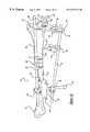
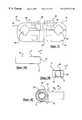
- FIGS. 1A and 1Billustrate a first exemplary construct of components of the external fixation system according to the teachings of the preferred embodiment of the present invention in operative association with a tibia.
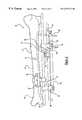
- FIG. 2illustrates a second exemplary construct of components of the external fixation system according to the teachings of the preferred embodiment of the present invention in operative association with a tibia, the second construct incorporating a compression/distraction arrangement.
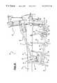
- FIGS. 3A and 3Billustrate a third exemplary construct of components of the external fixation system according to the teachings of the preferred embodiment of the present invention in operative association with a tibia, the third construct incorporating a ring assembly.
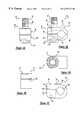
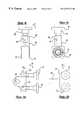
- FIGS. 4A and 4Bare views of a universal clamp assembly of the external fixation system according to the teachings of the preferred embodiment of the present invention.
- FIGS. 5A through 5Care views of a bar-to-bar clamp body of the external fixation system according to the teachings of the preferred embodiment of the present invention.
- FIGS. 6A and 6Bare views of a three pin clamp assembly of the external fixation system according to the teachings of the preferred embodiment of the present invention.
- FIGS. 7A and 7Bare views of a five pin clamp assembly of the external fixation system according to the teachings of the preferred embodiment of the present invention.
- FIGS. 8A and 8Bare views of a telescoping post of the external fixation system according to the teachings of the preferred embodiment of the present invention.
- FIGS. 9A and 9Bare views of a first ring connector assembly of the external fixation system according to the teachings of the preferred embodiment of the present invention.
- FIGS. 10A and 10Bare views of a second ring connector assembly of the external fixation system according to the teachings of the preferred embodiment of the present invention.
- FIGS. 11A through 11Dare views of a bone pin clamp body of the external fixation system according to the teachings of the preferred embodiment of the present invention.
- FIGS. 12A through 12Care views of a post assembly of the external fixation system according to the teachings of the preferred embodiment of the present invention.
- FIG. 13is a side elevational view a bar clamping unit of a compression/distraction arrangement of the external fixation system according to the teachings of the preferred embodiment of the present invention.
- FIGS. 14A through 14Care views of a variable connector body of the external fixation system according to the teachings of the preferred embodiment of the present invention.
- FIG. 15is a side elevational view of the bar clamping unit and threaded rod receiving unit the compression/distraction assembly of the external fixation system according to the teachings of the preferred embodiment of the present invention.
- FIGS. 1 through 3illustrated are three constructs of cooperating components of the system 10 for external fixation of bone according to the preferred embodiment of the present invention.
- a first construct of components of the system 10is shown securing a fracture 12 of a bone 14 .
- the system 10is illustrated as being used to secure a bone fracture 12 of a tibia 14 .
- the system 10is used to secure the bone portions 16 and 18 in a fixed relationship so as to permit the fractured portions to fuse properly.
- FIG. 2illustrates a second construct of the system 10 shown operatively attached to the tibia 14 .
- a third construct of the system 10is illustrated attached to the tibia 14 .
- FIGS. 1 through 3While the system 10 is shown throughout FIGS. 1 through 3 in conjunction with a tibia 14 , it will be appreciated that the system 10 may be used with other bones as well. It will also be appreciated that the three constructions illustrated in FIGS. 1 through 3 are merely exemplary applications.
- the components of the present inventionare illustrated to generally include a universal clamp assembly 20 , bar-to-bar clamp body 22 , a three pin clamp assembly 24 , a five pin clamp assembly 26 , a telescoping post 28 , a first ring connector assembly 30 , a second ring connector assembly 32 , a bone pin clamp body 34 , and a post assembly 36 .
- the componentsare illustrated to additionally include a compression/distraction arrangement 38 including a pair of clamping assemblies 40 and an externally threaded drive rod 42 .
- the componentsinclude a variable connector body 44 , a ring assembly 46 , and a plurality of cylindrical, smooth support rods 48 .
- the support rods 48include main support rods which are typically oriented to extend generally parallel to the axis of the bone 14 or at an acute angle relative to the bone 14 and supplemental support rods.
- the supplemental support rods 48 ′one of which is shown in FIG. 1B, may be provided in various lengths.
- the components of the system 10 of the present inventionmay be combined in an infinite number of combinations and orientations to secure and rigidly interconnect a plurality of bone screws or pins 50 which are engaged with the bone portions 16 and 18 .
- This flexibility of the system 10permits a surgeon to independently place a bone 50 at a limitless number of positions along the bone 14 or angular orientations with respect to the bone 14 .
- the universal clamp assembly 20 of the present inventionincludes a clamp portion 52 having first and second halves 54 and 56 which cooperate to define a bar receiving aperture 58 for receiving one of the support rods 48 , the telescoping post 28 or the post assembly 36 . It will be understood that in the exemplary embodiment the support rods 48 , telescoping post 28 and post assembly 36 each have a substantially identical diameter.
- the first and second halves 54 and 56include aligning apertures 60 and 62 , respectively, for receiving a locking bolt or fastener 64 .
- the aperture 62 of the second half 56includes a counterbored portion 66 for receiving a portion of a head 68 of the fastener 64 .
- An outer surface 70 of the first half 54is formed to include a serrated portion 72 having a plurality of serrations radially extending from the opening of the aperture 60 .
- the serrated portion 72is adapted to engage substantially identical serrated portions provided on cooperating components of the system 10 of the present invention as will be discussed below.
- An end 74 of the fastener 64 opposite the head 68is externally threaded.
- the fastener 64engages an internally threaded aperture of a cooperating component and is rotated to draw the cooperating component against the first half 56 , the first and second halves 56 of the clamp portion 52 are drawn together to thereby securely clamp one of the support rods 48 , for example, within the aperture 58 .
- the rod receiving aperture 58is sized to receive one of the support rods 48 , the telescoping post 28 or the post assembly 36 .
- the universal base clamp 20is the fundamental component of the system 10 of the present invention.
- the universal base clamp 20is designed to be easily placed anywhere along a support rod 48 , for example (even between two previously locked universal base clamps 20 ). This can be cone by sliding the first half 54 up the fastener 64 and then rotating the first half 54 ninety degrees. This feature allows a surgeon to add components during the application without the inconvenience of unlocking clamps 20 already in place.
- the bar-to-bar clamp body 22 of the present inventionis illustrated.
- the bar-to-bar clamp body 22is generally C-shaped to define a rod receiving aperture 80 and includes first and second ends 76 and 78 which are spaced apart by an opening 82 .
- the first and second ends 76 and 78include aligning apertures 84 and 86 , respectively, for receiving a fastener such as the fastener 64 described above with respect to the universal clamp assembly 20 .
- the aperture 86 of the second end 78is internally threaded.
- An outer surface 88 of the first end 76is formed to include a serrated portion 72 .
- the bar-to-bar clamp body 22is attached to a cooperating component of the system 10 of the present invention through engagement of the fastener 64 with the apertures 84 and 86 .
- the serrated portions 72 of the componentsare interlocked thereby preventing relative rotation. Tightening of the fastener 64 draws the ends 76 and 78 of the bar-to-bar clamp body 22 toward one another.
- a support rods 48 , telescoping post 28 or post assembly 36 positioned within the aperture 80is secured relative to the bar-to-bar clamp body 22 and in turn secured relative to the cooperating component.
- the pin clamp assembly 24 of the present inventionis illustrated.
- the pin clamp assembly 24is operative for receiving and securing up to three bone pins 50 engaged with the bone 14 .
- the bone pin clamp 28includes a main body member 90 and a cover member 92 .
- the main body member 90defines three bone pin rests 94 .
- the bone pin rests or grooves 94are substantially V-shaped and are operable to engage the sides of the bone pins 50 .
- the cover member 92 of the pin clamp assembly 24is able to be inserted over the bone pins 50 when the bone pins 50 are located in the grooves 94 .
- the cover member 92includes a pair of apertures 96 which each allow a threaded fastener 98 to pass through the cover member 32 and into a threaded aperture 100 of the main body member 90 . Tightening of the fasteners 98 rotationally and longitudinally secures the bone pins 50 relative to the pin clamp assembly 24 .
- the base member 90 and the cover member 92are both formed to integrally include cylindrical extensions 102 and 104 , respectfully.
- the ends of each of the cylindrical extensions 102 and 104are both formed to include a serrated portion 72 .
- Each of the cylindrical extensions 102 and 104includes an internally threaded aperture 106 sized to receive a fastener 64 .
- the five pin clamp assembly 26is shown particularly in FIGS. 7A and 7B.
- the construction of the five pin clamp assembly 26is identical to the construction of the three pin clamp assembly 26 , with the exception that the five pin clamp assembly 26 is formed to include two additional bone pin rests 94 .
- the five pin clamp assembly 26includes three bone pin rests 94 between the fasteners 98
- the three pin clamp assembly 24includes a single bone pin rest 94 between the fasteners. Due to the similarity between the two pin clamp assemblies 24 and 26 , like reference numbers are used in the drawings.
- the telescoping post 28includes a cylindrical post portion 108 and a mounting flange portion 110 .
- the cylindrical post portion 108has a diameter substantially equal to the diameter of the support rods 48 and thereby may be securely received within rod receiving apertures of cooperating components of the system 10 of the present invention.
- the mounting flange portion 110includes an aperture 112 for receiving a fastener 64 .
- a lower side 114 of the mounting flange portion 110includes a serrated portion 72 for cooperating with the serrated portions of cooperating components of the system 10 in a manner discussed above.
- the first ring connector assembly 30 of the present inventionis illustrated.
- the first ring connector assemblyincludes a main body 116 and a fastener 118 .
- An upper portion 120 of the main body 116defines a vertically extending aperture 122 which is internally threaded to receive the externally threaded fastener 118 .
- a lower portion 124 of the main body 116includes a pair of spaced apart sides 126 and 128 and an aperture 130 horizontally passing therethrough. Both of the sides 126 and 128 are formed to include a serrated portion 72 radially surrounding the aperture 130 which is adapted to interface with cooperating components of the system 10 including a serrated portion 72 in a manner discussed above.
- the fastener 118is adapted to pass through one of a plurality of apertures formed in a frame 132 of the ring assembly 46 for securing the first ring connector assembly 32 thereto.
- the second ring connector assembly 32 of the present inventionis illustrated. Rather than interfacing with cooperating components of the system 10 including a serrated portion 72 , the second ring connector assembly 32 is adapted to interface with cooperating components including a rod receiving aperture, such as the universal clamp assembly 20 and the bar-to-bar clamp body 22 .
- the second ring connector assembly 32includes a main body portion 132 and a cylindrical extension 134 . To facilitate clamping within one of the rod receiving apertures, the cylindrical extension 134 has a diameter substantially equal to the support rods 48 .
- the main body 132defines a pair of apertures 136 which are internally threaded for receiving a pair of threaded fasteners 118 identical to the fastener described with respect to the first ring connector assembly 30 .
- the fasteners 118are adapted to pass through a pair of the plurality of apertures formed in the frame 132 of the ring assembly 46 for securing the second ring connector assembly thereto.
- the bone pin clamp body 34 of the present inventiondefines an aperture 138 for receiving a bone pin 50 .
- the pin clamp body 34includes an upper flange portion 140 and a lower flange portion 142 which are separated by a gap 144 .
- the gap 144intersects the aperture 138 .
- the upper and lower flange portions 140 and 142are formed to include aligning apertures 146 and 148 for receiving a fastener 64 .
- the aperture 148 of the lower flange portion 142is internally threaded.
- An upper surface 150 of the upper flange portion 140includes a serrated portion 72 surrounding the aperture 146 .
- the serrated portion 72is adapted to interface with serrated portions of cooperating components of the system 10 of the present invention in a manner discussed above.
- a cooperating componentis secured to the bone pin clamp body 34 with a fastener 64
- tightening of the fastener 64causes the gap 144 between the upper and lower flange portions 140 and 142 to decrease and the aperture 138 to slightly constrict.
- a bone pin 50 disposed within the aperture 138is longitudinally and rotationally fixed with respect to the bone pin clamp body 34 .
- the post assembly 36generally includes a cylindrical sleeve 152 and a threaded fastener 154 .
- the cylindrical sleeve 152includes a central portion 156 and first and second enlarged ends 158 and 160 .
- the cylindrical sleeve 152has a diameter substantially equal to the diameter of the support rods 48 and can similarly interface with cooperating components including a rod receiving aperture, such as the universal clamp assembly 20 , in a manner discussed above.
- the cylindrical sleeve 152defines an elongated aperture 162 for receiving the fastener 154 .
- An outer end of the first enlarged end 158includes a serrated portion 72 surrounding the aperture 162 .
- the fastener 154extends beyond the serrated portion and is externally threaded.
- An opposite end of the fastener 154includes a recess 164 for receiving a tool (not shown) used to rotate the fastener 154 relative to the cylindrical sleeve 152 .
- the serrated portion 72is adapted to interface with serrated portions 72 of cooperating components of the system 10 of the present invention in a manner discussed above.
- the serrated portion 72is particularly intended to cooperate with the 3 pin and 5 pin clamp assemblies.
- the variable connector body 44 of the present inventiongenerally includes a main body 166 and a cylindrical portion 168 extending from the main body 166 .
- the main body 166includes a pair of spaced apart sides 170 and 172 and an internally threaded aperture 174 passing therethrough. Both of the sides 170 and 172 are formed to include a serrated portion 72 radially surrounding the aperture 174 which is adapted to interface with cooperating components of the system 10 including a serrated portion 72 in a manner discussed above.
- the cylindrical portion 168has a diameter substantially equal to the diameter of the support rods 48 and thereby may be securely received within rod receiving apertures of cooperating components of the system 10 of the present invention in a manner discussed above.
- the clamping assemblies 40 of the distraction arrangement 38each include a bar clamping unit 178 and a threaded rod receiving unit 180 .
- the bar clamping unit 178includes a lower portion 182 and a pair of substantially identical upper portions 184 .
- Each of the upper portions 184cooperates with the lower portion 182 to define an aperture 186 for receiving one of the support rods 48 .
- the upper portions 184each include an apertures 188 which each allow a threaded fastener 190 to pass therethrough and into an aligning threaded aperture 192 provided in the lower portion 182 . Tightening of the fasteners 190 secures the support rods 48 .
- a pair of the support rods 48are non-rotatably retained in a parallel and spaced apart relationship.
- the threaded rod receiving unit 180 of each of the clamping assemblies 40includes a first aperture (not specifically shown) which is internally threaded for receiving the drive rod 42 .
- the clamping assemblies 40additionally include a second aperture 194 oriented substantially perpendicular to the first aperture.
- the second aperture 194allows a threaded fastener 196 to pass therethrough and into an aligning internally threaded aperture 198 provided in the lower portion 182 of the bar clamping unit 178 for securing the bar clamping unit 178 to the threaded rod receiving unit 180 .
- the threads of the apertures receiving the drive rod 42progress in opposing directions.
- the fastener 190 of a first one of the bar clamping units 178 which is associated with one of the support rods 48must be loosened to permit the support rod 48 to slide within the aperture 186 .
- the fastener 190 of a second of the bar clamping units 178 which is associated with the other one of the support rods 48must be loosened to permit the support rod 48 to slide in its aperture 186 .
- one of the bar clamping units 178is permitted to translate with respect to one of the support rods 48 and the other of the clamping units 178 is permitted to translate relative to the other of the support rods 48 .
- rotation of the drive rod 42 in a first directioncauses relative movement between the clamping assemblies 40 such that they approach one another and the bone 14 is compressed.
- rotation of the drive rod 42 in a second directioncauses relative movement between the clamping assemblies 40 such that they diverge from one another and the bone 14 is distracted.
- the ring assembly 46 of the present inventionis shown in the exemplary construct of FIGS. 3A and 3B.
- a substantially identical ring assemblyis shown and described in commonly assigned U.S. Ser. No. 09/086,256, filed Jun. 28, 1998.
- U.S. Ser. No. 09/086,256is incorporated by reference as if fully set forth herein.
Landscapes
- Health & Medical Sciences (AREA)
- Orthopedic Medicine & Surgery (AREA)
- Life Sciences & Earth Sciences (AREA)
- Surgery (AREA)
- Medical Informatics (AREA)
- Engineering & Computer Science (AREA)
- Biomedical Technology (AREA)
- Heart & Thoracic Surgery (AREA)
- Nuclear Medicine, Radiotherapy & Molecular Imaging (AREA)
- Molecular Biology (AREA)
- Animal Behavior & Ethology (AREA)
- General Health & Medical Sciences (AREA)
- Public Health (AREA)
- Veterinary Medicine (AREA)
- Surgical Instruments (AREA)
- Clamps And Clips (AREA)
- Mutual Connection Of Rods And Tubes (AREA)
Abstract
Description
Claims (20)
Priority Applications (9)
| Application Number | Priority Date | Filing Date | Title |
|---|---|---|---|
| US09/422,377US6277119B1 (en) | 1999-10-21 | 1999-10-21 | External fixation system |
| PCT/US2000/028981WO2001028441A1 (en) | 1999-10-21 | 2000-10-20 | External fixation system |
| EP00973694AEP1229846B1 (en) | 1999-10-21 | 2000-10-20 | External fixation system |
| AU12178/01AAU1217801A (en) | 1999-10-21 | 2000-10-20 | External fixation system |
| AT00973694TATE540627T1 (en) | 1999-10-21 | 2000-10-20 | EXTERNAL FIXATION SYSTEM |
| JP2001531040AJP2003511192A (en) | 1999-10-21 | 2000-10-20 | External fixation system |
| US09/918,138US6616664B2 (en) | 1999-10-21 | 2001-07-30 | Clamp assembly for an external fixation system |
| US10/074,329US6702814B2 (en) | 1999-10-21 | 2002-02-12 | Clamp assembly for an external fixation system |
| PCT/US2003/004068WO2003068082A1 (en) | 1999-10-21 | 2003-02-12 | Clamp assembly for an external fixation system |
Applications Claiming Priority (2)
| Application Number | Priority Date | Filing Date | Title |
|---|---|---|---|
| US09/422,377US6277119B1 (en) | 1999-10-21 | 1999-10-21 | External fixation system |
| US10/074,329US6702814B2 (en) | 1999-10-21 | 2002-02-12 | Clamp assembly for an external fixation system |
Related Child Applications (1)
| Application Number | Title | Priority Date | Filing Date |
|---|---|---|---|
| US09/918,138Continuation-In-PartUS6616664B2 (en) | 1999-10-21 | 2001-07-30 | Clamp assembly for an external fixation system |
Publications (1)
| Publication Number | Publication Date |
|---|---|
| US6277119B1true US6277119B1 (en) | 2001-08-21 |
Family
ID=29272547
Family Applications (2)
| Application Number | Title | Priority Date | Filing Date |
|---|---|---|---|
| US09/422,377Expired - LifetimeUS6277119B1 (en) | 1999-10-21 | 1999-10-21 | External fixation system |
| US10/074,329Expired - LifetimeUS6702814B2 (en) | 1999-10-21 | 2002-02-12 | Clamp assembly for an external fixation system |
Family Applications After (1)
| Application Number | Title | Priority Date | Filing Date |
|---|---|---|---|
| US10/074,329Expired - LifetimeUS6702814B2 (en) | 1999-10-21 | 2002-02-12 | Clamp assembly for an external fixation system |
Country Status (5)
| Country | Link |
|---|---|
| US (2) | US6277119B1 (en) |
| EP (1) | EP1229846B1 (en) |
| JP (1) | JP2003511192A (en) |
| AU (1) | AU1217801A (en) |
| WO (2) | WO2001028441A1 (en) |
Cited By (35)
| Publication number | Priority date | Publication date | Assignee | Title |
|---|---|---|---|---|
| US20030069580A1 (en)* | 2001-10-09 | 2003-04-10 | Langmaid Michael N. | Adjustable fixator |
| US6565564B2 (en)* | 2000-12-14 | 2003-05-20 | Synthes U.S.A. | Multi-pin clamp and rod attachment |
| US6613049B2 (en)* | 2000-02-02 | 2003-09-02 | Robert A. Winquist | Adjustable bone stabilizing frame system |
| US6702814B2 (en) | 1999-10-21 | 2004-03-09 | Ebi, L.P. | Clamp assembly for an external fixation system |
| US20040059331A1 (en)* | 2002-09-17 | 2004-03-25 | Visionmed, L.L.C. | Unilateral fixator |
| US20040097922A1 (en)* | 2002-11-14 | 2004-05-20 | Visionmed, L.L.C. | Method for a using fixator device |
| US20040172020A1 (en)* | 2001-04-06 | 2004-09-02 | Jacques Beaurain | Spinal osteosynthesis device and preparation method |
| US20050107788A1 (en)* | 2001-12-12 | 2005-05-19 | Jacques Beaurain | Implant for osseous anchoring with polyaxial head |
| US20050240181A1 (en)* | 2004-04-23 | 2005-10-27 | Boomer Mark C | Spinal implant connectors |
| US20060142644A1 (en)* | 2002-06-06 | 2006-06-29 | Mulac Anthony J | Universal scissors joint apparatus |
| EP1702576A1 (en)* | 2005-03-16 | 2006-09-20 | Gian Luca Rovesti | A stabilising system for a hybrid external fixator |
| US20060241590A1 (en)* | 2005-04-25 | 2006-10-26 | Jean-Noel Bordeaux | Outrigger with locking mechanism |
| US20070012372A1 (en)* | 2005-07-01 | 2007-01-18 | Jay Richard M | Cover for fixation pin |
| US20070038217A1 (en)* | 2005-08-09 | 2007-02-15 | Brown Daniel G | Orthopaedic fixation clamp and method |
| US20070049930A1 (en)* | 2005-08-25 | 2007-03-01 | Jim Hearn | External fixation system and method of use |
| US20090125029A1 (en)* | 2007-11-08 | 2009-05-14 | Jai-Gon Seo | Device for Aligning and Guiding Femoral Resection Guide and Femoral Implant Impactor |
| US20090204156A1 (en)* | 2008-02-07 | 2009-08-13 | K2M, Inc. | Automatic lengthening bone fixation device |
| US20090275944A1 (en)* | 2008-05-02 | 2009-11-05 | Quantum Medical Concepts Llc | External Fixation and foot-supporting Device. |
| US20110112533A1 (en)* | 2009-11-06 | 2011-05-12 | Orthofix S.R.L. | Clamp for External Orthopaedic Fixing Device |
| US8162988B2 (en) | 2001-10-18 | 2012-04-24 | Ldr Medical | Plate for osteosynthesis device and method of preassembling such device |
| US8162984B2 (en) | 2009-02-20 | 2012-04-24 | K2M, Inc. | Forced growth axial growing spine device |
| US8221457B2 (en) | 2001-10-18 | 2012-07-17 | Ldr Medical | Progressive approach osteosynthesis device and preassembly method |
| US8343219B2 (en) | 2007-06-08 | 2013-01-01 | Ldr Medical | Intersomatic cage, intervertebral prosthesis, anchoring device and implantation instruments |
| US8523858B2 (en) | 2005-06-21 | 2013-09-03 | DePuy Synthes Products, LLC | Adjustable fixation clamp and method |
| US8758343B2 (en) | 2005-04-27 | 2014-06-24 | DePuy Synthes Products, LLC | Bone fixation apparatus |
| US8845691B2 (en) | 2003-09-01 | 2014-09-30 | Ldr Medical | Osseous anchoring implant with a polyaxial head and method for installing the implant |
| US20150209081A1 (en)* | 2012-07-25 | 2015-07-30 | Orthofix S.R.I. | Elongated pin for an external modular fixation system for temporary and/or permanent fixation applications and external modular fixation system |
| US20160278813A1 (en)* | 2013-03-15 | 2016-09-29 | Dne, Llc | External bone fixation system |
| US20170042579A1 (en)* | 2015-08-10 | 2017-02-16 | Stryker European Holdings I, Llc | Distraction tube with wire clamp |
| US20170252069A1 (en)* | 2015-12-03 | 2017-09-07 | Globus Medical, Inc. | External fixator assembly |
| US9936975B2 (en) | 2014-09-09 | 2018-04-10 | Integra Lifesciences Corporation | External fixation system |
| US9962188B2 (en) | 2013-10-29 | 2018-05-08 | Cardinal Health 247. Inc. | External fixation system and methods of use |
| US10258378B2 (en) | 2013-03-15 | 2019-04-16 | Dne, Llc | External bone fixation system |
| US11013545B2 (en) | 2018-05-30 | 2021-05-25 | Acumed Llc | Distraction/compression apparatus and method for bone |
| US11291476B2 (en) | 2016-06-10 | 2022-04-05 | Dne, Llc | External bone fixation system |
Families Citing this family (83)
| Publication number | Priority date | Publication date | Assignee | Title |
|---|---|---|---|---|
| WO2004026156A1 (en)* | 2002-09-18 | 2004-04-01 | Haci Kutlu | Stable dynamic axial fixator-ii (holyfix) |
| EP1635720A1 (en)* | 2003-06-26 | 2006-03-22 | SYNTHES AG Chur | Double jaws with an elastic closing action for distraction-compression apparatus |
| US20060200005A1 (en)* | 2003-09-17 | 2006-09-07 | Levahn Intellectual Property Holding Company, Llc | Low profile, handle-in-between surgical scissors clamp |
| PL1723343T3 (en)* | 2004-03-10 | 2008-01-31 | Synthes Gmbh | Device for mutual positioning of longitudinal building components |
| US7717939B2 (en) | 2004-03-31 | 2010-05-18 | Depuy Spine, Inc. | Rod attachment for head to head cross connector |
| CN100475278C (en)* | 2004-04-19 | 2009-04-08 | 斯恩蒂斯有限公司 | Elastic element, medical technical device and bone-fixing device |
| ES2326269T3 (en)* | 2004-08-20 | 2009-10-06 | Stryker Trauma Sa | TIGHTENING ELEMENT AND GASKET ELEMENT. |
| US7717938B2 (en) | 2004-08-27 | 2010-05-18 | Depuy Spine, Inc. | Dual rod cross connectors and inserter tools |
| US20060085010A1 (en)* | 2004-09-29 | 2006-04-20 | The Cleveland Clinic Foundation | Minimally invasive method and apparatus for placing facet screws and fusing adjacent vertebrae |
| WO2006058221A2 (en) | 2004-11-24 | 2006-06-01 | Abdou Samy M | Devices and methods for inter-vertebral orthopedic device placement |
| US20060155276A1 (en)* | 2005-01-11 | 2006-07-13 | Walulik Stephen B | Bone fixation assembly and related method |
| DE502005005095D1 (en)* | 2005-02-09 | 2008-10-02 | Stryker Trauma Sa | Insert for a clamping element, clamping element with such an insert and articulated connection formed therefrom |
| US7575575B2 (en) | 2005-03-18 | 2009-08-18 | Ron Anthon Olsen | Adjustable splint for osteosynthesis with modular components |
| US20060271045A1 (en)* | 2005-05-27 | 2006-11-30 | Depuy Spine, Inc. | Spinal cross-connector |
| US7306601B2 (en)* | 2005-06-10 | 2007-12-11 | Quantum Medical Concepts, Inc. | External fixation system with provisional brace |
| GB2427141B (en)* | 2005-06-13 | 2010-12-22 | Intelligent Orthopaedics Ltd | Fixator |
| ES2246744B1 (en)* | 2005-10-11 | 2006-12-01 | Implantvet, S.L. | ARTICULATION FOR MUTUAL SOLIDARIZATION BETWEEN BARS AND / OR NEEDLES IN AN EXTERNAL FIXING DEVICE FOR THE REDUCTION OF OSE FRACTURES. |
| US7749224B2 (en)* | 2005-12-08 | 2010-07-06 | Ebi, Llc | Foot plate fixation |
| US7731738B2 (en) | 2005-12-09 | 2010-06-08 | Orthopro, Llc | Cannulated screw |
| US20070158513A1 (en)* | 2006-01-12 | 2007-07-12 | Levahn Intellectual Property Holding Company, Llc | Surgical clamp and tool support system |
| EP1820461B1 (en) | 2006-02-21 | 2009-08-05 | Stryker Trauma SA | Clamping and articulation element |
| US7708736B2 (en)* | 2006-02-22 | 2010-05-04 | Extraortho, Inc. | Articulation apparatus for external fixation device |
| EP1839605B1 (en) | 2006-03-31 | 2008-12-10 | Stryker Trauma SA | External fixator element having a rough ablated surface |
| US20080071145A1 (en)* | 2006-09-19 | 2008-03-20 | Levahn Intellectual Property Holding Company, Llc | Support Clamp For Retractor Bar Stock Of Generally Rectangular Cross-Section |
| US8361117B2 (en) | 2006-11-08 | 2013-01-29 | Depuy Spine, Inc. | Spinal cross connectors |
| US8152121B2 (en)* | 2006-12-28 | 2012-04-10 | Carrier Corporation | Bracket for thermal expansion valve bulb |
| EP1987792B1 (en) | 2007-05-03 | 2011-06-22 | Medartis AG | Fixing device, combination of a fixing device with a long element, assembly with such a combination and osteosynthesis set |
| EP2197372B1 (en)* | 2007-09-27 | 2016-04-13 | Zimmer, Inc. | Clamping apparatus for external fixation and stabilization |
| WO2009129142A1 (en)* | 2008-04-16 | 2009-10-22 | Synthes Usa, Llc | Apparatus and method for use with fracture table to reposition bone portions |
| US8187274B2 (en)* | 2008-06-30 | 2012-05-29 | Depuy Products, Inc. | External fixator |
| WO2010065795A1 (en) | 2008-12-03 | 2010-06-10 | Eminent Spine Llc | Spinal Cross-Connector and Method for Use of Same |
| ES2451507T3 (en) | 2009-05-15 | 2014-03-27 | Stryker Trauma Ag | Fixing flange |
| EP2294995B1 (en) | 2009-09-11 | 2018-04-04 | Stryker European Holdings I, LLC | Easy to clean clamping device |
| USD632791S1 (en) | 2009-09-11 | 2011-02-15 | Stryker Trauma Ag | Connector |
| EP2294994B1 (en)* | 2009-09-11 | 2018-04-04 | Stryker European Holdings I, LLC | External fixation component |
| IT1396145B1 (en)* | 2009-11-05 | 2012-11-16 | Citieffe Srl | MULTI-PURPOSE EXTERNAL FIXER. |
| US8764806B2 (en) | 2009-12-07 | 2014-07-01 | Samy Abdou | Devices and methods for minimally invasive spinal stabilization and instrumentation |
| RU2433796C1 (en)* | 2010-03-15 | 2011-11-20 | Государственное образовательное учреждение высшего профессионального образования "Саратовский государственный медицинский университет им. В.И. Разумовского" Министерства здравоохранения и социального развития Российской Федерации (ГОУ ВПО Саратовский ГМУ им. В.И.Разумовского Минздравсоцразвития РФ) | Method of combined osteosynthesis of fractures of long tubular bones |
| EP2399532A1 (en)* | 2010-06-24 | 2011-12-28 | Franz Bentele | Jaw for an external fixator and articulation using such jaws |
| US9138260B2 (en)* | 2010-07-01 | 2015-09-22 | Zimmer, Inc. | Multi-locking external fixation clamp |
| ES2541831T3 (en) | 2010-10-07 | 2015-07-27 | Stryker Trauma Sa | Coupling element for an external fixing device |
| WO2012051312A1 (en)* | 2010-10-12 | 2012-04-19 | Extraortho, Inc. | Single lock external fixation clamp arrangement |
| WO2012051255A1 (en) | 2010-10-12 | 2012-04-19 | Extraortho, Inc. | External fixation surgical clamp with swivel |
| US8728078B2 (en) | 2010-11-04 | 2014-05-20 | Zimmer, Inc. | Clamping assembly with links |
| WO2012078897A1 (en) | 2010-12-09 | 2012-06-14 | Extraortho, Inc. | Revolving lock for external fixation clamps |
| EP2648633B1 (en) | 2010-12-09 | 2016-05-18 | Zimmer, Inc. | External fixation clamp with cam driven jaw |
| USD683461S1 (en) | 2010-12-14 | 2013-05-28 | Stryker Trauma Sa | Hinge coupling |
| USD704840S1 (en) | 2010-12-14 | 2014-05-13 | Stryker Trauma Sa | Hinge coupling |
| EP2465454B1 (en) | 2010-12-14 | 2015-04-08 | Stryker Trauma SA | Fixation clamp with thumbwheel |
| ES2540256T3 (en) | 2010-12-14 | 2015-07-09 | Stryker Trauma Sa | Fixing clamp |
| USD720853S1 (en) | 2010-12-14 | 2015-01-06 | Stryker Trauma Sa | Fixation clamp |
| EP2465455B1 (en) | 2010-12-14 | 2015-04-08 | Stryker Trauma SA | Fixation clamp |
| JP6106662B2 (en) | 2011-05-17 | 2017-04-05 | ジンマー,インコーポレイティド | External fixed clamping system using a starting mechanism and stored spring energy |
| USD682426S1 (en) | 2011-06-14 | 2013-05-14 | Stryker Trauma Sa | Fixation clamp |
| USD663030S1 (en) | 2011-06-14 | 2012-07-03 | Styker Trauma SA | Fixation clamp |
| US8845728B1 (en) | 2011-09-23 | 2014-09-30 | Samy Abdou | Spinal fixation devices and methods of use |
| US9414862B2 (en) | 2011-10-24 | 2016-08-16 | Warsaw Orthopedic, Inc. | Bone fastener for a spinal surgical system |
| US20130226240A1 (en) | 2012-02-22 | 2013-08-29 | Samy Abdou | Spinous process fixation devices and methods of use |
| JP5408812B2 (en)* | 2012-03-16 | 2014-02-05 | 株式会社スター精機 | Pipe joint |
| US9198767B2 (en) | 2012-08-28 | 2015-12-01 | Samy Abdou | Devices and methods for spinal stabilization and instrumentation |
| US9924969B2 (en) | 2012-09-04 | 2018-03-27 | Zimmer, Inc. | External fixation |
| US9301782B2 (en) | 2012-09-04 | 2016-04-05 | Zimmer, Inc. | External fixation |
| US9320617B2 (en) | 2012-10-22 | 2016-04-26 | Cogent Spine, LLC | Devices and methods for spinal stabilization and instrumentation |
| RU2572302C2 (en)* | 2013-07-05 | 2016-01-10 | Государственное бюджетное образовательное учреждение высшего профессионального образования "Дагестанская государственная медицинская академия" Министерства здравоохранения РФ | Device for bone fragment reduction in ilizarov's apparatus |
| JP6931283B2 (en)* | 2013-12-11 | 2021-09-01 | プロ メッド インストルメンツ ゲーエムベーハーPro Med Instruments Gmbh | Surgical wound instrument system and how to use it |
| US9962187B2 (en) | 2014-08-11 | 2018-05-08 | Zimmer, Inc. | External fixation |
| RU2572300C1 (en)* | 2014-09-17 | 2016-01-10 | Государственное бюджетное образовательное учреждение высшего профессионального образования "Дагестанская государственная медицинская академия" Министерства здравоохранения РФ | Device for extrafocal osteosynthesis of open shin fractures |
| EP3795102B1 (en)* | 2014-10-01 | 2024-09-18 | Stabiliz Orthopaedics, LLC | Anatomic external fixation device |
| WO2016205128A2 (en) | 2015-06-17 | 2016-12-22 | Nathan Erickson | Ankle fixation system |
| US10857003B1 (en) | 2015-10-14 | 2020-12-08 | Samy Abdou | Devices and methods for vertebral stabilization |
| US9872707B2 (en) | 2015-12-03 | 2018-01-23 | Globus Medical, Inc. | External fixator assembly |
| US9943337B2 (en) | 2015-12-03 | 2018-04-17 | Globus Medical, Inc. | External fixator assembly |
| US10682160B2 (en) | 2015-12-03 | 2020-06-16 | Globus Medical, Inc. | External fixator assembly |
| US10010350B2 (en) | 2016-06-14 | 2018-07-03 | Stryker European Holdings I, Llc | Gear mechanisms for fixation frame struts |
| US10744000B1 (en) | 2016-10-25 | 2020-08-18 | Samy Abdou | Devices and methods for vertebral bone realignment |
| US10973648B1 (en) | 2016-10-25 | 2021-04-13 | Samy Abdou | Devices and methods for vertebral bone realignment |
| US10874433B2 (en) | 2017-01-30 | 2020-12-29 | Stryker European Holdings I, Llc | Strut attachments for external fixation frame |
| US11517351B2 (en) | 2018-06-04 | 2022-12-06 | Daniel Chan | External fixation devices for posterior pelvic compression and methods of use |
| US11179248B2 (en) | 2018-10-02 | 2021-11-23 | Samy Abdou | Devices and methods for spinal implantation |
| RU2750521C1 (en)* | 2020-09-14 | 2021-06-29 | Федеральное Государственное бюджетное образовательное учреждение высшего образования Дагестанский государственный медицинский университет Министерства здравоохранения Российской Федерации Даггосмедуниверситет | Device for primary stabilization of diaphyseal fractures of tibia in polytrauma |
| US20220133356A1 (en)* | 2020-11-04 | 2022-05-05 | QuikFix, LLC | Clamping devices for external fixation device |
| CN113693674B (en)* | 2021-08-30 | 2023-08-15 | 万春友 | Fixing support |
| US12226323B2 (en)* | 2021-10-05 | 2025-02-18 | Spineology Inc. | Floating clamp for spinal surgeries |
Citations (42)
| Publication number | Priority date | Publication date | Assignee | Title |
|---|---|---|---|---|
| US2391693A (en)* | 1943-12-09 | 1945-12-25 | Zimmer Mfg Company | Surgical splint |
| US2391537A (en)* | 1943-09-27 | 1945-12-25 | Anderson Roger | Ambulatory rotating reduction and fixation splint |
| GB2033758A (en)* | 1978-10-28 | 1980-05-29 | Aesculap Werke Ag | Fracture fixing appliance |
| SU780838A1 (en)* | 1979-01-09 | 1980-11-23 | Курганский Научно-Исследовательский Институт Экспериментальной И Клинической Ортопедии И Травматологии | Wire holder for compression-distraction apparatus |
| US4258708A (en)* | 1977-07-22 | 1981-03-31 | Giulio Gentile | Articulated positioning system for devices adapted to externally exert a holding action on bone tissues |
| US4488542A (en) | 1981-11-27 | 1984-12-18 | Per Helland | External setting and correction device for the treatment of bone fractures |
| US4553273A (en) | 1983-11-23 | 1985-11-19 | Henry Ford Hospital | Vertebral body prosthesis and spine stabilizing method |
| US4600000A (en) | 1982-09-16 | 1986-07-15 | Edwards Charles C | External fixation system |
| US4657550A (en) | 1984-12-21 | 1987-04-14 | Daher Youssef H | Buttressing device usable in a vertebral prosthesis |
| US4662365A (en) | 1982-12-03 | 1987-05-05 | Ortopedia Gmbh | Device for the external fixation of bone fragments |
| US5211664A (en) | 1992-01-14 | 1993-05-18 | Forschungsinstitut, Davos Laboratorium Fur Experimentelle Chirugie | Shell structure for bone replacement |
| US5261912A (en) | 1990-08-21 | 1993-11-16 | Synthes (U.S.A.) | Implant for an osteosynthesis device, in particular for spinal column correction |
| US5352224A (en) | 1990-11-29 | 1994-10-04 | Howmedica Gmbh | Correction implant for the human vertebral column |
| US5403315A (en) | 1992-04-29 | 1995-04-04 | Danek Medical, Inc. | Positionable spinal fixation device |
| US5451225A (en) | 1993-06-10 | 1995-09-19 | Texas Scottish Rite Hospital For Crippled Children | Fastener for external fixation device wires and pins |
| US5454810A (en)* | 1990-02-05 | 1995-10-03 | Pohl; Anthony P. | External fixation device |
| US5520689A (en) | 1992-06-04 | 1996-05-28 | Synthes (U.S.A.) | Osteosynthetic fastening device |
| US5527311A (en) | 1991-11-13 | 1996-06-18 | Howmedica Gmbh | Support for the human spine |
| US5534002A (en) | 1993-01-04 | 1996-07-09 | Danek Medical, Inc. | Spinal fixation system |
| US5542946A (en) | 1994-05-27 | 1996-08-06 | Sofamor S.N.C. | Hook for an occipito-cervical rod or plate of an occipito-cervical osteosynthesis instrumentation |
| US5601552A (en) | 1994-03-18 | 1997-02-11 | Sofamor, S.N.C. | Fixing device for a rigid transverse connection device between rods of a spinal osteosynthesis system |
| US5624440A (en) | 1996-01-11 | 1997-04-29 | Huebner; Randall J. | Compact small bone fixator |
| US5643258A (en) | 1994-08-10 | 1997-07-01 | Howmedica Gmbh | Device for stabilizing long bones |
| US5676666A (en) | 1994-08-23 | 1997-10-14 | Spinetech, Inc. | Cervical spine stabilization system |
| US5683389A (en) | 1994-12-05 | 1997-11-04 | Smith & Nephew, Inc. | External fixator for distal radius fractures |
| US5683390A (en) | 1994-02-22 | 1997-11-04 | Howmedica Gmbh | Correcting a spinal column |
| US5688274A (en) | 1995-10-23 | 1997-11-18 | Fastenetix Llc. | Spinal implant device having a single central rod and claw hooks |
| US5688272A (en) | 1995-03-30 | 1997-11-18 | Danek Medical, Inc. | Top-tightening transverse connector for a spinal fixation system |
| US5702393A (en) | 1995-12-07 | 1997-12-30 | Groupe Lepine | Assembly device for elongate components of osteosynthesis, especially spinal, equipment |
| US5709681A (en) | 1995-09-19 | 1998-01-20 | Pennig; Dietmar | Device for osteosynthesis |
| US5741252A (en) | 1996-03-25 | 1998-04-21 | Synthes U.S.A. | Adjustable clamp for bone fixation element |
| US5741254A (en) | 1993-04-19 | 1998-04-21 | Stryker Corporation | Implant for an ostheosynthesis device, in particular for the spine |
| US5746741A (en) | 1996-05-06 | 1998-05-05 | Tufts University | External fixator system |
| US5752954A (en) | 1994-09-06 | 1998-05-19 | Howmedica International | External fixation device |
| US5782833A (en) | 1996-12-20 | 1998-07-21 | Haider; Thomas T. | Pedicle screw system for osteosynthesis |
| US5827283A (en)* | 1996-03-21 | 1998-10-27 | Groiso; Jorge Abel | Device and method for locating two bones into a desired relative position |
| US5863293A (en) | 1996-10-18 | 1999-01-26 | Spinal Innovations | Spinal implant fixation assembly |
| US5888221A (en) | 1992-08-11 | 1999-03-30 | Gelbard; Steven D. | Spinal stabilization implant system |
| US5891144A (en) | 1996-05-10 | 1999-04-06 | Jaquet Orthopedie S.A. | External fixator |
| US5921985A (en) | 1998-02-10 | 1999-07-13 | Texas Scottish Rite Hospital | External fixation device and method |
| US5961515A (en) | 1995-03-01 | 1999-10-05 | Smith & Nephew, Inc. | External skeletal fixation system |
| US5997537A (en)* | 1998-05-28 | 1999-12-07 | Electro Biology, Inc. | Ring system for external fixation of bone and related method |
Family Cites Families (15)
| Publication number | Priority date | Publication date | Assignee | Title |
|---|---|---|---|---|
| US3749429A (en)* | 1970-09-22 | 1973-07-31 | Brown & Root | Universal offshore pipeline riser clamp assembly |
| DE2113319C3 (en)* | 1971-03-19 | 1975-12-04 | Rheinmetall Gmbh, 4000 Duesseldorf | Belt feeder for automatic weapons |
| US4607829A (en)* | 1984-09-24 | 1986-08-26 | Suska Charles R | Clamping apparatus |
| US4718151A (en)* | 1984-11-08 | 1988-01-12 | Minnesota Scientific, Inc. | Retractor apparatus |
| US4620533A (en)* | 1985-09-16 | 1986-11-04 | Pfizer Hospital Products Group Inc. | External bone fixation apparatus |
| CH684928A5 (en)* | 1990-12-10 | 1995-02-15 | Jaquet Orthopedie | external fixator. |
| US5860728A (en)* | 1993-02-08 | 1999-01-19 | Mag Instrument, Inc. | Holder clamp assembly |
| US5908181A (en)* | 1995-01-04 | 1999-06-01 | Valles-Navarro; Alfredo | Support for cameras |
| US5620442A (en) | 1995-05-12 | 1997-04-15 | Bailey; Kirk J. | Method and apparatus for external fixation of small bones |
| AU1544497A (en)* | 1996-01-30 | 1998-08-18 | Implico B.V. | Means for anti-rotationally fixing two components together, particularly of an osteosynthetic fixator |
| US5863292A (en)* | 1996-09-26 | 1999-01-26 | Tosic; Aleksandar | Articulated external orthopedic fixation system and method of use |
| US6056748A (en) | 1998-02-20 | 2000-05-02 | Weiner; Lon S. | Modular fixator assembly |
| US6162223A (en) | 1999-04-09 | 2000-12-19 | Smith & Nephew, Inc. | Dynamic wrist fixation apparatus for early joint motion in distal radius fractures |
| US6273445B1 (en)* | 1999-06-14 | 2001-08-14 | Sunrise Medical Hhg Inc. | Wheel mounting assembly and wheelchair therewith |
| US6277119B1 (en) | 1999-10-21 | 2001-08-21 | Electro-Biology, Inc. | External fixation system |
- 1999
- 1999-10-21USUS09/422,377patent/US6277119B1/ennot_activeExpired - Lifetime
- 2000
- 2000-10-20JPJP2001531040Apatent/JP2003511192A/enactivePending
- 2000-10-20AUAU12178/01Apatent/AU1217801A/ennot_activeAbandoned
- 2000-10-20EPEP00973694Apatent/EP1229846B1/ennot_activeExpired - Lifetime
- 2000-10-20WOPCT/US2000/028981patent/WO2001028441A1/enactiveApplication Filing
- 2002
- 2002-02-12USUS10/074,329patent/US6702814B2/ennot_activeExpired - Lifetime
- 2003
- 2003-02-12WOPCT/US2003/004068patent/WO2003068082A1/ennot_activeApplication Discontinuation
Patent Citations (45)
| Publication number | Priority date | Publication date | Assignee | Title |
|---|---|---|---|---|
| US2391537A (en)* | 1943-09-27 | 1945-12-25 | Anderson Roger | Ambulatory rotating reduction and fixation splint |
| US2391693A (en)* | 1943-12-09 | 1945-12-25 | Zimmer Mfg Company | Surgical splint |
| US4258708A (en)* | 1977-07-22 | 1981-03-31 | Giulio Gentile | Articulated positioning system for devices adapted to externally exert a holding action on bone tissues |
| GB2033758A (en)* | 1978-10-28 | 1980-05-29 | Aesculap Werke Ag | Fracture fixing appliance |
| SU780838A1 (en)* | 1979-01-09 | 1980-11-23 | Курганский Научно-Исследовательский Институт Экспериментальной И Клинической Ортопедии И Травматологии | Wire holder for compression-distraction apparatus |
| US4488542A (en) | 1981-11-27 | 1984-12-18 | Per Helland | External setting and correction device for the treatment of bone fractures |
| US4600000A (en) | 1982-09-16 | 1986-07-15 | Edwards Charles C | External fixation system |
| US4662365A (en) | 1982-12-03 | 1987-05-05 | Ortopedia Gmbh | Device for the external fixation of bone fragments |
| US4553273A (en) | 1983-11-23 | 1985-11-19 | Henry Ford Hospital | Vertebral body prosthesis and spine stabilizing method |
| US4657550A (en) | 1984-12-21 | 1987-04-14 | Daher Youssef H | Buttressing device usable in a vertebral prosthesis |
| US5454810A (en)* | 1990-02-05 | 1995-10-03 | Pohl; Anthony P. | External fixation device |
| US5261912A (en) | 1990-08-21 | 1993-11-16 | Synthes (U.S.A.) | Implant for an osteosynthesis device, in particular for spinal column correction |
| US5352224A (en) | 1990-11-29 | 1994-10-04 | Howmedica Gmbh | Correction implant for the human vertebral column |
| US5527311A (en) | 1991-11-13 | 1996-06-18 | Howmedica Gmbh | Support for the human spine |
| US5211664A (en) | 1992-01-14 | 1993-05-18 | Forschungsinstitut, Davos Laboratorium Fur Experimentelle Chirugie | Shell structure for bone replacement |
| US5403315A (en) | 1992-04-29 | 1995-04-04 | Danek Medical, Inc. | Positionable spinal fixation device |
| US5520689A (en) | 1992-06-04 | 1996-05-28 | Synthes (U.S.A.) | Osteosynthetic fastening device |
| US5888221A (en) | 1992-08-11 | 1999-03-30 | Gelbard; Steven D. | Spinal stabilization implant system |
| US5534002A (en) | 1993-01-04 | 1996-07-09 | Danek Medical, Inc. | Spinal fixation system |
| US5562662A (en) | 1993-01-04 | 1996-10-08 | Danek Medical Inc. | Spinal fixation system and method |
| US5741254A (en) | 1993-04-19 | 1998-04-21 | Stryker Corporation | Implant for an ostheosynthesis device, in particular for the spine |
| US5451225A (en) | 1993-06-10 | 1995-09-19 | Texas Scottish Rite Hospital For Crippled Children | Fastener for external fixation device wires and pins |
| US5683390A (en) | 1994-02-22 | 1997-11-04 | Howmedica Gmbh | Correcting a spinal column |
| US5743911A (en) | 1994-03-18 | 1998-04-28 | Sofamor S.N.C. | Fixing device for a rigid transverse connection device between rods of a spinal osteosynthesis system |
| US5601552A (en) | 1994-03-18 | 1997-02-11 | Sofamor, S.N.C. | Fixing device for a rigid transverse connection device between rods of a spinal osteosynthesis system |
| US5542946A (en) | 1994-05-27 | 1996-08-06 | Sofamor S.N.C. | Hook for an occipito-cervical rod or plate of an occipito-cervical osteosynthesis instrumentation |
| US5643258A (en) | 1994-08-10 | 1997-07-01 | Howmedica Gmbh | Device for stabilizing long bones |
| US5676666A (en) | 1994-08-23 | 1997-10-14 | Spinetech, Inc. | Cervical spine stabilization system |
| US5752954A (en) | 1994-09-06 | 1998-05-19 | Howmedica International | External fixation device |
| US6080153A (en)* | 1994-09-06 | 2000-06-27 | Howmedica International | External fixation device |
| US5683389A (en) | 1994-12-05 | 1997-11-04 | Smith & Nephew, Inc. | External fixator for distal radius fractures |
| US5961515A (en) | 1995-03-01 | 1999-10-05 | Smith & Nephew, Inc. | External skeletal fixation system |
| US5688272A (en) | 1995-03-30 | 1997-11-18 | Danek Medical, Inc. | Top-tightening transverse connector for a spinal fixation system |
| US5709681A (en) | 1995-09-19 | 1998-01-20 | Pennig; Dietmar | Device for osteosynthesis |
| US5688274A (en) | 1995-10-23 | 1997-11-18 | Fastenetix Llc. | Spinal implant device having a single central rod and claw hooks |
| US5702393A (en) | 1995-12-07 | 1997-12-30 | Groupe Lepine | Assembly device for elongate components of osteosynthesis, especially spinal, equipment |
| US5624440A (en) | 1996-01-11 | 1997-04-29 | Huebner; Randall J. | Compact small bone fixator |
| US5827283A (en)* | 1996-03-21 | 1998-10-27 | Groiso; Jorge Abel | Device and method for locating two bones into a desired relative position |
| US5741252A (en) | 1996-03-25 | 1998-04-21 | Synthes U.S.A. | Adjustable clamp for bone fixation element |
| US5746741A (en) | 1996-05-06 | 1998-05-05 | Tufts University | External fixator system |
| US5891144A (en) | 1996-05-10 | 1999-04-06 | Jaquet Orthopedie S.A. | External fixator |
| US5863293A (en) | 1996-10-18 | 1999-01-26 | Spinal Innovations | Spinal implant fixation assembly |
| US5782833A (en) | 1996-12-20 | 1998-07-21 | Haider; Thomas T. | Pedicle screw system for osteosynthesis |
| US5921985A (en) | 1998-02-10 | 1999-07-13 | Texas Scottish Rite Hospital | External fixation device and method |
| US5997537A (en)* | 1998-05-28 | 1999-12-07 | Electro Biology, Inc. | Ring system for external fixation of bone and related method |
Non-Patent Citations (3)
| Title |
|---|
| Howmedica brochure entitled "Howmedica Trauma Simple Solutions", copyright 1998, 26 pages. |
| Howmedica, Inc. manual entitled "External Fixation of a Complex Femoral Fracture, Frame Construction Manual", copyright 1981, 24 pages. |
| Synthes brochure entitled "The AO/ASIF Hybrid Fixator Technique Guide", copyright 1995, 25 pages. |
Cited By (73)
| Publication number | Priority date | Publication date | Assignee | Title |
|---|---|---|---|---|
| US6702814B2 (en) | 1999-10-21 | 2004-03-09 | Ebi, L.P. | Clamp assembly for an external fixation system |
| US20040044344A1 (en)* | 2000-02-02 | 2004-03-04 | Winquist Robert A. | Adjustable bone stabilizing frame system |
| US7931650B2 (en)* | 2000-02-02 | 2011-04-26 | Zimmer Technology, Inc. | Adjustable bone stabilizing frame system |
| US6613049B2 (en)* | 2000-02-02 | 2003-09-02 | Robert A. Winquist | Adjustable bone stabilizing frame system |
| US8696668B2 (en) | 2000-02-02 | 2014-04-15 | Zimmer, Inc. | Adjustable bone stabilizing frame system |
| US20030191467A1 (en)* | 2000-12-14 | 2003-10-09 | Hoffmann-Clair Mindy L. | Multipin clamp and rod attachment |
| US20030191468A1 (en)* | 2000-12-14 | 2003-10-09 | Synthes U.S.A. | Multipin clamp and rod attachment |
| US8372073B2 (en)* | 2000-12-14 | 2013-02-12 | Sythes USA, LLC | Multi-pin clamp and rod attachment |
| US6565564B2 (en)* | 2000-12-14 | 2003-05-20 | Synthes U.S.A. | Multi-pin clamp and rod attachment |
| US20100160972A1 (en)* | 2000-12-14 | 2010-06-24 | Mindy Lynn Hoffman | Multi-Pin Clamp and Rod Attachmenton |
| US7041103B2 (en) | 2000-12-14 | 2006-05-09 | Synthes (Usa) | Multipin clamp and rod attachment |
| US7699848B2 (en) | 2000-12-14 | 2010-04-20 | Synthes Usa, Llc | Multipin clamp and rod attachment |
| US7507248B2 (en) | 2001-04-06 | 2009-03-24 | Ldr Medical | Spinal osteosynthesis device and preparation method |
| US20040172020A1 (en)* | 2001-04-06 | 2004-09-02 | Jacques Beaurain | Spinal osteosynthesis device and preparation method |
| US7261713B2 (en) | 2001-10-09 | 2007-08-28 | Synthes (Usa) | Adjustable fixator |
| US8382757B1 (en) | 2001-10-09 | 2013-02-26 | Synthes Usa, Llc | Adjustable fixator |
| US20030069580A1 (en)* | 2001-10-09 | 2003-04-10 | Langmaid Michael N. | Adjustable fixator |
| US8221457B2 (en) | 2001-10-18 | 2012-07-17 | Ldr Medical | Progressive approach osteosynthesis device and preassembly method |
| US8162988B2 (en) | 2001-10-18 | 2012-04-24 | Ldr Medical | Plate for osteosynthesis device and method of preassembling such device |
| US9326795B2 (en) | 2001-12-12 | 2016-05-03 | Ldr Medical | Implant for osseous anchoring with polyaxial head |
| US20050107788A1 (en)* | 2001-12-12 | 2005-05-19 | Jacques Beaurain | Implant for osseous anchoring with polyaxial head |
| US7749163B2 (en)* | 2002-06-06 | 2010-07-06 | Peak Performance Company | Universal scissors joint apparatus |
| US20060142644A1 (en)* | 2002-06-06 | 2006-06-29 | Mulac Anthony J | Universal scissors joint apparatus |
| US20070282338A1 (en)* | 2002-09-17 | 2007-12-06 | Ebi, L.P. | Unilateral fixator |
| US8388619B2 (en) | 2002-09-17 | 2013-03-05 | Sixfix Inc. | Unilateral fixator |
| US20040059331A1 (en)* | 2002-09-17 | 2004-03-25 | Visionmed, L.L.C. | Unilateral fixator |
| US7282052B2 (en) | 2002-09-17 | 2007-10-16 | Ebi, L.P. | Unilateral fixator |
| US8419732B2 (en) | 2002-11-14 | 2013-04-16 | Sixfix, Inc. | Method for using a fixator device |
| US20040097922A1 (en)* | 2002-11-14 | 2004-05-20 | Visionmed, L.L.C. | Method for a using fixator device |
| US20110103676A1 (en)* | 2002-11-14 | 2011-05-05 | Extraortho, Inc. | Method for using a fixator device |
| US8845691B2 (en) | 2003-09-01 | 2014-09-30 | Ldr Medical | Osseous anchoring implant with a polyaxial head and method for installing the implant |
| US20050240181A1 (en)* | 2004-04-23 | 2005-10-27 | Boomer Mark C | Spinal implant connectors |
| US20060235384A1 (en)* | 2005-03-16 | 2006-10-19 | Rovesti Gian L | Stabilizing system for a hybrid external fixator |
| EP1702576A1 (en)* | 2005-03-16 | 2006-09-20 | Gian Luca Rovesti | A stabilising system for a hybrid external fixator |
| US7722609B2 (en) | 2005-04-25 | 2010-05-25 | Synthes Usa, Llc | Outrigger with locking mechanism |
| US9273715B2 (en) | 2005-04-25 | 2016-03-01 | DePuy Synthes Products, Inc. | Outrigger with locking mechanism |
| US20060241590A1 (en)* | 2005-04-25 | 2006-10-26 | Jean-Noel Bordeaux | Outrigger with locking mechanism |
| US8758343B2 (en) | 2005-04-27 | 2014-06-24 | DePuy Synthes Products, LLC | Bone fixation apparatus |
| US9545266B2 (en) | 2005-06-21 | 2017-01-17 | DePuy Synthes Products, Inc. | Adjustable fixation clamp and method |
| US8523858B2 (en) | 2005-06-21 | 2013-09-03 | DePuy Synthes Products, LLC | Adjustable fixation clamp and method |
| US20070012372A1 (en)* | 2005-07-01 | 2007-01-18 | Jay Richard M | Cover for fixation pin |
| US20070038217A1 (en)* | 2005-08-09 | 2007-02-15 | Brown Daniel G | Orthopaedic fixation clamp and method |
| US20090036891A1 (en)* | 2005-08-09 | 2009-02-05 | Zimmer Technology, Inc. | Orthopaedic fixation clamp and method |
| US8029505B2 (en)* | 2005-08-25 | 2011-10-04 | Synthes Usa, Llc | External fixation system and method of use |
| US20070049930A1 (en)* | 2005-08-25 | 2007-03-01 | Jim Hearn | External fixation system and method of use |
| US8343219B2 (en) | 2007-06-08 | 2013-01-01 | Ldr Medical | Intersomatic cage, intervertebral prosthesis, anchoring device and implantation instruments |
| US10751187B2 (en) | 2007-06-08 | 2020-08-25 | Ldr Medical | Intersomatic cage, intervertebral prosthesis, anchoring device and implantation instruments |
| US20090125029A1 (en)* | 2007-11-08 | 2009-05-14 | Jai-Gon Seo | Device for Aligning and Guiding Femoral Resection Guide and Femoral Implant Impactor |
| US8777995B2 (en) | 2008-02-07 | 2014-07-15 | K2M, Inc. | Automatic lengthening bone fixation device |
| US20090204156A1 (en)* | 2008-02-07 | 2009-08-13 | K2M, Inc. | Automatic lengthening bone fixation device |
| US9339307B2 (en) | 2008-02-07 | 2016-05-17 | K2M, Inc. | Automatic lengthening bone fixation device |
| US8192434B2 (en) | 2008-05-02 | 2012-06-05 | Huebner Randall J | External fixation and foot-supporting device |
| US20090275944A1 (en)* | 2008-05-02 | 2009-11-05 | Quantum Medical Concepts Llc | External Fixation and foot-supporting Device. |
| US8162984B2 (en) | 2009-02-20 | 2012-04-24 | K2M, Inc. | Forced growth axial growing spine device |
| US20110112533A1 (en)* | 2009-11-06 | 2011-05-12 | Orthofix S.R.L. | Clamp for External Orthopaedic Fixing Device |
| US10631896B2 (en)* | 2012-07-25 | 2020-04-28 | Orthofix S.R.L. | Elongated pin for an external modular fixation system for temporary and/or permanent fixation applications and external modular fixation system |
| US20150209081A1 (en)* | 2012-07-25 | 2015-07-30 | Orthofix S.R.I. | Elongated pin for an external modular fixation system for temporary and/or permanent fixation applications and external modular fixation system |
| US20160278813A1 (en)* | 2013-03-15 | 2016-09-29 | Dne, Llc | External bone fixation system |
| US11259843B2 (en) | 2013-03-15 | 2022-03-01 | Dne, Llc | External bone fixation system |
| US10022152B2 (en)* | 2013-03-15 | 2018-07-17 | Dne, Llc | External bone fixation system |
| US11986218B2 (en) | 2013-03-15 | 2024-05-21 | Trilliant Surgical, Llc | External bone fixation system |
| US10258378B2 (en) | 2013-03-15 | 2019-04-16 | Dne, Llc | External bone fixation system |
| US10687853B2 (en) | 2013-03-15 | 2020-06-23 | Dne, Llc | External bone fixation system |
| US9962188B2 (en) | 2013-10-29 | 2018-05-08 | Cardinal Health 247. Inc. | External fixation system and methods of use |
| US9936975B2 (en) | 2014-09-09 | 2018-04-10 | Integra Lifesciences Corporation | External fixation system |
| US10660672B2 (en) | 2014-09-09 | 2020-05-26 | Integra Lifesciences Corporation | External fixation system |
| US10531896B2 (en)* | 2015-08-10 | 2020-01-14 | Stryker European Holdings I, Llc | Distraction tube with wire clamp |
| US20170042579A1 (en)* | 2015-08-10 | 2017-02-16 | Stryker European Holdings I, Llc | Distraction tube with wire clamp |
| US10070890B2 (en)* | 2015-12-03 | 2018-09-11 | Globus Medical Inc | External fixator assembly |
| US20170252069A1 (en)* | 2015-12-03 | 2017-09-07 | Globus Medical, Inc. | External fixator assembly |
| US11291476B2 (en) | 2016-06-10 | 2022-04-05 | Dne, Llc | External bone fixation system |
| US12016592B2 (en) | 2016-06-10 | 2024-06-25 | Trilliant Surgical, Llc | External bone fixation system |
| US11013545B2 (en) | 2018-05-30 | 2021-05-25 | Acumed Llc | Distraction/compression apparatus and method for bone |
Also Published As
| Publication number | Publication date |
|---|---|
| AU1217801A (en) | 2001-04-30 |
| EP1229846A4 (en) | 2003-02-05 |
| US20020151892A1 (en) | 2002-10-17 |
| WO2003068082A1 (en) | 2003-08-21 |
| US6702814B2 (en) | 2004-03-09 |
| WO2001028441A1 (en) | 2001-04-26 |
| EP1229846A1 (en) | 2002-08-14 |
| EP1229846B1 (en) | 2012-01-11 |
| JP2003511192A (en) | 2003-03-25 |
| WO2003068082B1 (en) | 2005-01-20 |
Similar Documents
| Publication | Publication Date | Title |
|---|---|---|
| US6277119B1 (en) | External fixation system | |
| US6616664B2 (en) | Clamp assembly for an external fixation system | |
| US6482206B2 (en) | Method and apparatus for external fixation of bones | |
| EP2672907B1 (en) | Clamp for temporary or definitive external orthopaedic fixation, and external fixation system comprising said clamp | |
| US6520961B1 (en) | Method and apparatus for external fixation of a hinged joint | |
| US5976136A (en) | Method and apparatus for external bone fixator | |
| AU691400B2 (en) | External fixator for distal radius fractures | |
| US5891144A (en) | External fixator | |
| US8372073B2 (en) | Multi-pin clamp and rod attachment | |
| US7449023B2 (en) | Method and apparatus for the external fixation and correction of bone | |
| US6010501A (en) | Method and apparatus for external fixation of small bones | |
| US5931837A (en) | Method and apparatus for external fixation of an ankle | |
| US20060155276A1 (en) | Bone fixation assembly and related method | |
| EP0835079A1 (en) | Method and apparatus for external fixation of small bones | |
| WO1999060950A2 (en) | Ring system for external fixation of bone and related method | |
| EP1482845B1 (en) | Clamp assembly for an external fixation system | |
| HK1186948B (en) | Clamp for temporary or definitive external orthopaedic fixation, and external fixation system comprising said clamp |
Legal Events
| Date | Code | Title | Description |
|---|---|---|---|
| AS | Assignment | Owner name:ELECTRO-BIOLOGY, INC., NEW JERSEY Free format text:ASSIGNMENT OF ASSIGNORS INTEREST;ASSIGNORS:WALULIK, STEPHEN B.;BAILEY, KIRK J.;CURRY, SEAN P.;AND OTHERS;REEL/FRAME:010462/0660 Effective date:19991216 | |
| STCF | Information on status: patent grant | Free format text:PATENTED CASE | |
| FPAY | Fee payment | Year of fee payment:4 | |
| AS | Assignment | Owner name:EBI, L.P., NEW JERSEY Free format text:ASSIGNMENT OF ASSIGNORS INTEREST;ASSIGNOR:ELECTRO-BIOLOGY, INC.;REEL/FRAME:019287/0692 Effective date:20070515 | |
| AS | Assignment | Owner name:BANK OF AMERICA, N.A., AS ADMINISTRATIVE AGENT FOR Free format text:SECURITY AGREEMENT;ASSIGNORS:LVB ACQUISITION, INC.;BIOMET, INC.;REEL/FRAME:020362/0001 Effective date:20070925 | |
| AS | Assignment | Owner name:EBI, LLC, NEW JERSEY Free format text:CHANGE OF NAME;ASSIGNOR:EBI, INC.;REEL/FRAME:021387/0450 Effective date:20080227 Owner name:EBI, LLC,NEW JERSEY Free format text:CHANGE OF NAME;ASSIGNOR:EBI, INC.;REEL/FRAME:021387/0450 Effective date:20080227 | |
| FPAY | Fee payment | Year of fee payment:8 | |
| AS | Assignment | Owner name:EBI, LLC, NEW JERSEY Free format text:CORRECTIVE ASSIGNMENT TO CORRECT THE ASSIGNOR INCORRECTLY IDENTIFIED AS EBI, INC. ON ORIGINAL RECORDATION COVERSHEET SHOULD HAVE BEEN IDENTIFIED AS EBI, L.P. PREVIOUSLY RECORDED ON REEL 021387 FRAME 0450;ASSIGNOR:EBI, L.P.;REEL/FRAME:022727/0859 Effective date:20080227 Owner name:EBI, LLC,NEW JERSEY Free format text:CORRECTIVE ASSIGNMENT TO CORRECT THE ASSIGNOR INCORRECTLY IDENTIFIED AS EBI, INC. ON ORIGINAL RECORDATION COVERSHEET SHOULD HAVE BEEN IDENTIFIED AS EBI, L.P. PREVIOUSLY RECORDED ON REEL 021387 FRAME 0450. ASSIGNOR(S) HEREBY CONFIRMS THE ORIGINAL CONVEYANCE TEXT APPEARING IN NAME CHANGE DOCUMENTATION REFLECTS EBI, L.P. IS NOW KNOWN AS EBI, LLC.;ASSIGNOR:EBI, L.P.;REEL/FRAME:022727/0859 Effective date:20080227 Owner name:EBI, LLC, NEW JERSEY Free format text:CORRECTIVE ASSIGNMENT TO CORRECT THE ASSIGNOR INCORRECTLY IDENTIFIED AS EBI, INC. ON ORIGINAL RECORDATION COVERSHEET SHOULD HAVE BEEN IDENTIFIED AS EBI, L.P. PREVIOUSLY RECORDED ON REEL 021387 FRAME 0450. ASSIGNOR(S) HEREBY CONFIRMS THE ORIGINAL CONVEYANCE TEXT APPEARING IN NAME CHANGE DOCUMENTATION REFLECTS EBI, L.P. IS NOW KNOWN AS EBI, LLC.;ASSIGNOR:EBI, L.P.;REEL/FRAME:022727/0859 Effective date:20080227 | |
| FPAY | Fee payment | Year of fee payment:12 | |
| AS | Assignment | Owner name:BIOMET MANUFACTURING, LLC, INDIANA Free format text:ASSIGNMENT OF ASSIGNORS INTEREST;ASSIGNOR:EBI, LLC;REEL/FRAME:031307/0797 Effective date:20130925 | |
| AS | Assignment | Owner name:BIOMET, INC., INDIANA Free format text:RELEASE OF SECURITY INTEREST IN PATENTS RECORDED AT REEL 020362/ FRAME 0001;ASSIGNOR:BANK OF AMERICA, N.A., AS ADMINISTRATIVE AGENT;REEL/FRAME:037155/0133 Effective date:20150624 Owner name:LVB ACQUISITION, INC., INDIANA Free format text:RELEASE OF SECURITY INTEREST IN PATENTS RECORDED AT REEL 020362/ FRAME 0001;ASSIGNOR:BANK OF AMERICA, N.A., AS ADMINISTRATIVE AGENT;REEL/FRAME:037155/0133 Effective date:20150624 |