US6277077B1 - Catheter including ultrasound transducer with emissions attenuation - Google Patents
Catheter including ultrasound transducer with emissions attenuationDownload PDFInfo
- Publication number
- US6277077B1 US6277077B1US09/192,763US19276398AUS6277077B1US 6277077 B1US6277077 B1US 6277077B1US 19276398 AUS19276398 AUS 19276398AUS 6277077 B1US6277077 B1US 6277077B1
- Authority
- US
- United States
- Prior art keywords
- ultrasound
- catheter
- transducer
- dampening
- transducers
- Prior art date
- Legal status (The legal status is an assumption and is not a legal conclusion. Google has not performed a legal analysis and makes no representation as to the accuracy of the status listed.)
- Expired - Lifetime
Links
Images


Classifications
- A—HUMAN NECESSITIES
- A61—MEDICAL OR VETERINARY SCIENCE; HYGIENE
- A61B—DIAGNOSIS; SURGERY; IDENTIFICATION
- A61B8/00—Diagnosis using ultrasonic, sonic or infrasonic waves
- A61B8/12—Diagnosis using ultrasonic, sonic or infrasonic waves in body cavities or body tracts, e.g. by using catheters
- A—HUMAN NECESSITIES
- A61—MEDICAL OR VETERINARY SCIENCE; HYGIENE
- A61B—DIAGNOSIS; SURGERY; IDENTIFICATION
- A61B8/00—Diagnosis using ultrasonic, sonic or infrasonic waves
- A61B8/44—Constructional features of the ultrasonic, sonic or infrasonic diagnostic device
- A61B8/4444—Constructional features of the ultrasonic, sonic or infrasonic diagnostic device related to the probe
- A61B8/445—Details of catheter construction
Definitions
- the present inventionrelates to ultrasound transducers.
- the inventionrelates to ultrasound transducers mounted on catheters that include ultrasound dampening regions to improve the performance thereof.
- endoscopic visualization of the treatment site within the bodyis unavailable or does not assist the clinician in guiding the needed medical devices to the treatment site.
- SVTsupra-ventricular tachycardia
- AFatrial fibrillation
- AFLatrial flutter
- VTventricular tachycardia
- SVT, AFL, AF and VTare conditions in the heart which cause abnormal electrical signals to be generated, causing irregular beating of the heart.
- a procedure for diagnosing and treating SVT or VTinvolves measuring the electrical activity of the heart using an electrophysiology (EP) catheter introduced into the heart via the patient's vasculature.
- the cathetercarries mapping electrodes which are positioned within the heart and used to measure electrical activity.
- the position of the catheter within the heartis ascertained using fluoroscopic images.
- the mapping electrodesmeasure the electrical activity of the heart at the position of the catheter.
- a mapis created by correlating locations in the heart determined by viewing the position of the catheter with the fluoroscope.
- the physicianuses the map to identify the region of the endocardium which he believes to be the source of the abnormal electrical activity.
- An ablation catheteris then inserted through the patient's vasculature and into the heart where it is used to ablate the region identified by the physician.
- an ablation catheteris maneuvered into the right or left atrium where it is used to create elongated ablation lesions in the heart.
- An improvement over fluoroscopyis a display system using a fixed coordinate system for determining the relative locations of medical devices within the body.
- a display system using a fixed coordinate systemcan avoid the tracking errors inherent in fluoroscopic imaging that can make it difficult to guide medical devices to the desired locations within the body.
- Ultrasoundcan be used to track medical devices relative to a fixed internal coordinate system.
- Such an ultrasound tracking systemuses at least four ultrasound transducers.
- An ultrasound tracking systemcan be based on the time difference measured from the time an ultrasound pulse is transmitted by one transducer to the time it is received by another transducer. Given the velocity of sound in tissue and blood of approximately 1570 m/sec, the distance between the transmitter and receiver can be calculated. This process of distance measurement with sound is called sonomicrometry. Distance measurements between multiple transducers are used to triangulate the positions of the transducers in a three-dimensional coordinate system. A minimum of four transducers create a three-dimensional coordinate system, with three transducers defining a plane and the fourth defining a position above or below the plane. Additional transducers may be used for redundancy. Once the coordinate system is established, additional transducers on medical devices may be used to calculate the locations of the devices relative to the coordinate system.
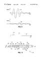
- FIG. 1shows an example of transmit and receive waveforms for a typical sonomicrometry procedure.
- Transmission waveform 26is a pulse initiated at time t 1 by a transmitting transducer.
- Reception waveform 27corresponds to the voltage generated by a receiving transducer that intercepts the transmit pulse.
- the time t 2is the time at which the reception waveform crosses a detection threshold 28 . The time difference between t 1 and t 2 may then be used to calculate the distance between the transmitter and the receiver.
- the detection threshold 28is needed to filter out detected signals that are too small to have been generated by a measurement pulse. Such signals could result from crosstalk with signals on nearby wires or from random noise.
- transducersshould exhibit fully isotropic operation, that is, the same transmit or receive (or both) generation or detection sensitivity in all directions. Isotropic operation allows measurement of the same distance amount regardless of the orientation of the transducers. Accurate distance measurement is desirable for measurements within the human body, especially within the heart or other vital organs, both for accurate placement of the sensing devices and for accurate location of areas for monitoring or surgery.
- Sonometrics Corp. of London, Ontario, Canadahas developed a sonomicrometer system based on a family of small transducers which might be sewn onto living tissue. These transducers typically consist of either small, flat squares of piezoelectric ceramic 30 (FIG. 2) in a spherical bead of epoxy (not shown) or small cylinders of piezoelectric ceramic 34 (FIG. 3) in a spherical bead of epoxy (not shown).
- Piezoelectric ceramicsconvert electrical energy into vibrational energy, and vice versa.
- the vibrationresults from the piezoelectric ceramic expanding in one direction, which causes it to contract in another direction.
- expansion by the top and bottomcauses the sides to contract.
- expansion by the top and bottomcauses the thickness and the circumference to contract.
- Each direction of expansion/contractionis termed a vibrational mode.
- the expansion and contractioncauses an ultrasound signal to be emitted from each surface of the transducer when transmitting. Similarly, a received ultrasound signal causes a receiving transducer to expand and contract, generating electricity.
- the epoxy beadserves as a lens to focus the ultrasound signal.
- the frequency of expansion and contractionis determined by the size of the transducer.
- the speed of sound in the piezoelectric ceramicis about 4000 m/sec. This speed is equal to the wavelength times the frequency, and the wavelength is twice the direction of expansion/contraction.
- a length and width d of 0.052 inchesrelate to a frequency of 1.5 MHz.
- the wavelength of the circumferential vibrationis the average circumference, and the wavelength of the length vibration is twice the length, so a length of 0.052 inches and a circumference of 0.105 inches relate to a frequency of 1.5 MHz.
- Line 40 in FIGS. 2 and 3passes through the center of the transducer in a direction parallel to a longitudinal axis of a catheter (not shown) on which either of the transuducers 30 or 34 may be mounted.
- Line 38indicates a direction perpendicular to line 40 , where line 38 passes through the center of the transducer.
- the angle ⁇denotes the angle from line 38 in the direction of line 40 .
- the transducers shown in FIGS. 2 and 3are anisotropic because the physical geometry of the transducer contributes to the radiation emitted and received.
- line 38lies in a radial plane perpendicular to line 40 through the center of transducer 34 .
- the cylindrical symmetry of transducer 34suggests that the emissions or receptions in this plane would also be symmetric.
- anisotropy in emissionsresults as the radiation shifts from emission off the cylindrical side to emission off the flat end 44 of the transducer.
- anisotropyresults from interference between the sides and the top.
- anisotropyresults from the physical dimensions of a receiving transducer at the same angles. This is because reception is symmetric to transmission. For example, if an ideal emission source is moved around a stationary receiving transducer having a given geometric shape, this results in the same received waveform as when an ideal receiver is moved around a stationary transmitting transducer having the same geometric shape.
- FIG. 4illustrates the experimental results from catheters comprising small cylinders of piezoelectric ceramic around the catheter body.
- the amplitude of the signal(either transmitted or received) varies significantly with the angle ⁇ .
- Similar irregular resultswere observed with and without a spherical bead of epoxy around the ceramic.
- these devicestypically would exhibit phase reversals in their response at a ⁇ of about 30 degrees, this effect being due to a switch from emission off the cylindrical surface 42 of the ceramic to emission off the ends 44 of the cylinder (see FIG. 3 ).
- Emission off the ends 44is 180 degrees out of phase with emission off the surface 42 because one expands while the other contracts, causing interference. These responses were considered unacceptable.
- FIG. 5illustrates exemplary waveforms showing how the interference from anisotropic radiation may result in distance measurement variations.
- Transmitted waveform 50is pulsed at time t 1 .
- Received waveform 52rises above the detection threshold 54 at time t 3 .
- the actual time that the wave should be receivedis at time t 2 (compare with FIG. 1 ).
- the wavelooks like it is about to be detected, but the anisotropy results in destructive interference between time t 2 and time t 3 .
- the distance measurement of the wave in FIG. 5will be longer than the actual distance.
- anisotropycauses the distance measurement to vary based on the relative angle between the transmitter and the receiver.
- FIGS. 6A and 6Bshow a second problem that results when a catheter 60 has both a transmitting transducer 62 and a receiving transducer 64 .
- FIG. 6Ashows that desirably, a measurement pulse generated by transmitting transducer 62 should be received by receiving transducer 64 at a time corresponding to the distance 66 .
- the pulsemay propagate more rapidly along the catheter body than through the surrounding blood and tissues. In such a situation the distance measured, signified by the numeral 68 in FIG. 6B, will be shorter than the actual distance.
- an error 70results.
- the angular transmission and detection response of a transducer assemblycan be improved if the geometry and structure of the device are carefully considered.
- the present inventionachieves this result by employing ultrasound dampening regions adjacent to the transducers to produce more isotropic transmission and reception.
- Sonic energydoes not propagate in a vacuum. Ultrasonic energy does not propagate well in air nor do piezoelectric transducers couple energy effectively into air, especially at frequencies up to and beyond 1 MHz. Consequently an ultrasound dampening region including air or a vacuum is proposed to inhibit emission and reception from selected surfaces of the transducer.
- a catheter according to the present inventionincludes an elongated body member, an ultrasound transducer located on the elongated body member, and dampening means for forming an ultrasound dampening region adjacent to a portion of the ultrasound transducer.
- the ultrasound transduceris configured to transmit or to receive an ultrasound signal.
- the ultrasound dampening regionis configured to improve uniformity of communication of the ultrasound signal in three-dimensional space.
- a catheter according to the present inventionincludes an elongated body member, a plurality of ultrasound transducers located on the elongated body member, first dampening means for forming an ultrasound dampening region adjacent to a portion of the ultrasound transducer, and second dampening means for modifying a conducted ultrasound signal conducted by the elongated body member to inhibit detection thereof.
- the plurality of ultrasound transducersare configured to transmit and to receive a plurality of ultrasound signals.
- the ultrasound dampening regionis configured to improve uniformity of corresponding communicated ultrasound signals in three-dimensional space.
- the second dampening meansis located between one of the plurality of ultrasound transducers that sends the communicated ultrasound signals and another that receives the communicated ultrasound signals.
- an ultrasound transducer assemblyincludes an ultrasound transducer and dampening means for forming an ultrasound dampening region adjacent to a portion of the ultrasound transducer.
- the ultrasound transduceris configured to transmit or to receive an ultrasound signal.
- the ultrasound dampening regionis configured to improve uniformity of communication of the ultrasound signal in three-dimensional space.
- a method of making a catheter according to the present inventionincludes the steps of providing an elongated body member and an ultrasound transducer, attaching the ultrasound transducer to the elongated body member, and forming an ultrasound dampening region adjacent to a portion of the ultrasound transducer.
- the ultrasound transduceris configured to transmit or to receive an ultrasound signal.
- the ultrasound dampening regionis formed such that uniformity of the ultrasound signal is improved in three-dimensional space.
- a method of making a catheter according to the present inventionincludes the steps of providing an elongated body member and a plurality of ultrasound transducers, attaching the plurality of ultrasound transducers to the elongated body member, forming a first ultrasound dampening region adjacent to a portion of at least one of the plurality of ultrasound transducers, and forming a second ultrasound dampening region between a sending one and a receiving one of the plurality of ultrasound transducers.
- the plurality of ultrasound transducersare configured to transmit and receive a plurality of ultrasound signals.
- the first ultrasound dampening regionis formed such that uniformity of a corresponding communicated ultrasound signal is improved in three-dimensional space.
- the second ultrasound dampening regionis formed to modify a conducted ultrasound signal conducted by the elongated body member to inhibit detection thereof.
- a catheter according to the present inventionis made by one of the previous methods.
- An object of the present inventionis to improve the uniformity of an ultrasound signal in three-dimensional space.
- a further object of the present inventionis to reduce the conduction of ultrasound signals through the catheter between ultrasound transducers.
- FIG. 1is a graph of amplitude versus time for transmitted and received waveforms.
- FIG. 2is an elevation view of an existing rectangular transducer.
- FIG. 3is an elevation view of an existing cylindrical transducer taken on the longitudinal axis of the cylinder.
- FIG. 4is a graph of amplitude versus angle for the transducer of FIG. 3 .
- FIG. 5is a graph of amplitude versus time for transmitted and received waveforms.
- FIGS. 6A and 6Bare cross-sectional views of a catheter taken on the longitudinal axis of the catheter.
- FIG. 7Ais a cross-sectional view of a catheter according to the present invention taken on the longitudinal axis of the catheter.
- FIG. 7Bis a cross-sectional view taken on line 7 B— 7 B of FIG. 7 A.
- FIG. 8is a graph of amplitude versus angle for two sets of transducers, one with an ultrasound dampening region and one without.
- FIG. 9is a graph of pressure versus time for the two sets of transducers measured in FIG. 8 .
- FIG. 10is a cross-sectional view of a reference catheter according to the present invention taken on the longitudinal axis of the catheter.
- FIG. 11Ais a perspective view of a basket catheter according to the present invention taken on the longitudinal axis of the catheter.
- FIG. 11Bis a perspective view of the catheter of FIG. 11A taken on the radial axis of the catheter.
- FIG. 11Cis a cross-sectional view of one of the arms of the catheter of FIG. 11A taken along the long axis of the arm.
- FIG. 11Dis a cross-sectional view taken along line 11 D— 11 D of FIG. 11 C.
- FIG. 12is a perspective view of another basket catheter according to the present invention taken on the longitudinal axis of the catheter.
- FIG. 13Ais a cross-sectional view of an arm of the basket catheter of FIG. 11 taken along the long axis of the arm.
- FIG. 13Bis a cross-sectional view taken on line 13 B— 13 B of FIG. 13 A.
- FIG. 14is a plan view of a transducer shim according to the present invention.
- FIG. 15Ais a cross-sectional view of an arm of the basket catheter of FIG. 12 taken along the long axis of the arm including the transducer shim of FIG. 14 .
- FIG. 15Bis a cross-sectional view taken on line 15 B— 15 B of FIG. 15 A.
- FIG. 16Ais a plan view of another device including the transducer assembly of the present invention.
- FIG. 16Bis a cross-sectional view taken along line 16 B— 16 B of FIG. 16 A.
- Transducer assemblies according to the present inventionmay be mounted on various catheters.
- the catheter typescan include reference catheters, marking/ablation catheters, mapping catheters, and linear lesion ablation catheters. To avoid duplication recognizable to one skilled in the art, when the following description discusses a specific type of catheter, discussion of all other types of catheters at the level of ordinary skill in the art is assumed.
- Transducer assemblies according to the present inventionmay be employed with catheters used in an ultrasound tracking system.
- transducerrefers to devices which are transmit-only, receive only, or capable of both transmission and reception.
- communicationrefers to transmission, reception, or both transmission and reception.
- an emissionrefers to radiation communicated by a transducer.
- such a systemmay include one or more reference catheters and an additional catheter.
- Each of the reference catheterscarries one or more of the ultrasound transducers, with there being a total of at least four such transducers employed during use of the system.
- the reference catheter transducerscan function as ultrasound receivers by converting acoustic pressure to voltage, and as ultrasound transmitters by converting voltage to acoustic pressure. At least four of the reference catheter transducers must be configured to receive and transmit ultrasound signals.
- the reference catheter transducersare used to generate the base coordinate system.
- the additional cathetercarries at least one ultrasound transducer which preferably functions as an ultrasound receiver but which may also function as a transmitter or a transmitter/receiver.
- the position of the additional catheteris displayed relative to the positions of the reference transducers.
- Each transmitting reference transduceris separately made to emit acoustic pulses that are received by each of the receiving reference transducers so that the distances therebetween can be calculated using the respective time it takes for an acoustic pulse to travel between each pair of the reference transducers. These distances are triangulated to establish the positions of the reference transducers relative to each other, and therefore to establish a three-dimensional coordinate system.
- Such a tracking systemis disclosed in copending application No. 08/905,090 filed Aug. 1, 1997, entitled “System for Electrode Localization Using Ultrasound”, commonly owned by the assignee of the present application, the disclosure of which is incorporated herein by reference.
- the terms “tracking” and “localization”are used interchangeably in the copending application and the present application.
- the localization systemis operated using the same vibration frequencies for all transducers.
- the optimal operating frequency for the systemis determined by considering the resonant frequencies of the ultrasound transducers used for the catheters in the system.
- the resonant frequenciesare determined by the size and shape of the transducer, for example, square or cylindrical.
- FIGS. 7A and 7Bshow portions of a catheter 123 formed in accordance with the subject invention.
- a piezoelectric ceramic cylindrical transducer 120is mounted on an inner shaft 122 of the catheter 123 .
- An adhesive 124can be used to bond the inner cylindrical electrode 126 of the transducer 120 and the outer surface 128 of the inner shaft 122 (see FIG. 7 B).
- the interior of the inner shaft 122contains electrical wires 130 for connection to the transducer 120 and other electrical devices attached to the catheter (see also FIG. 7 B).
- the inner shaft 122may be extruded from a flexible polymeric material such as a polyether polyamide copolymer. Wall thicknesses may be on the order of 0.005 inches.
- outer shafts 132 and 134Attached to each end of inner shaft 122 are outer shafts 132 and 134 which make up the body of the catheter.
- the outer shafts 132 and 134also may be fabricated from a polyether polyamide copolymer or other polymeric material.
- the outer shafts 132 and 134are attached to the inner shaft 122 by heat fusion or by the use of an epoxy material.
- the outer shafts 132 and 134are brought up to approximately 0.020 inches from the end of the transducer 120 , and any material to effect the joint preferably shall not be permitted in the gap between the outer shafts 132 and 134 and the transducer 120 .
- This space defined by the end of the transducer 120 , the end of the outer shaft 134 , and a portion of the inner shaft 122are ultrasound dampening regions 136 a and 136 b.
- a covering 138may be pulled over and shrunk onto the transducer 120 and the ends of the outer shafts 132 and 134 .
- the covering 138may be a polymeric material, preferably polyethylene terepthalate (PET), and preferably with a wall thickness of less than 0.001 inches.
- PETpolyethylene terepthalate
- a thin layer of adhesive 140may be placed between the covering 138 and the transducer 120 , such adhesive preferably not penetrating into the ultrasound dampening region 136 at the ends of the transducer 120 .
- the covering 138may be heat fused over the ends of the outer shafts 132 and 134 .
- the covering 138may also be adhered to the outer shafts 132 and 134 with adhesive 142 .
- a sealant 144may be used to help seal the air or vacuum within ultrasound dampening region 136 .
- the covering 138may also be applied as a conformal coating. Areas desired to remain non-coated may be masked while the coating is applied, and then unmasked.
- the coatingmay be parylene applied in a vapor deposition process, or may be urethane applied by dipping. To prevent the coating from filling the ultrasound dampening region 136 , the region is preferably filled with an ultrasound blocking material as discussed below.
- the ultrasound dampening region 136may be filled with an ultrasound blocking material that itself contains air.
- ultrasound blocking materialsinclude highly scattering or absorbing materials such as highly loaded silicone rubber materials, composites of (typically shredded) lead loaded silicone rubber and epoxy, possibly glass microspheres in an epoxy matrix, foam, balsa wood, high-density polyethylene (HDPE) (such as that commercially available under the brand TYVEK), or expanded polytetrafluoroethylene (ePTFE).
- the ultrasound blocking materialis ePTFE with a thickness of 0.020 inches.
- the physical extent of the ultrasound dampening region at the end of the ceramic cylindersis dictated primarily by catheter assembly techniques. Even a small gap of less than 0.001 inches would be sufficient to prevent conduction of ultrasound from the end of the transducer 120 . Bending of the catheter should not allow the outer shafts 132 and 134 to come in contact with the transducer 120 .
- the covering 138 and sealant 144should be sufficiently strong so as to not allow body fluids to penetrate into the ultrasound dampening region 136 , and to provide additional protection against parts of the catheter breaking off and entering the body, such as if the transducer were to crack or shatter.
- ultrasound dampening regions 136are preferably located adjacent to the opposed end faces of cylindrical transducer 120 . This attenuates the emission and reception from these surfaces.
- the cylindrical outer surfaceis not adjacent to one of the ultrasound dampening regions 136 , allowing transmission of ultrasound from this surface. Reduction of the ultrasound communication associated with the end faces results in improved uniformity of the ultrasound signal in three-dimensional space.
- Adhesives 124 , 140 , and 142are preferably a penetrating epoxy material.
- An important property of adhesive 124is that it flows into the interface between transducer 120 and inner shaft 122 , preferably completely underneath transducer 120 . This improves the mechanical grounding and the beam profile of transducer 120 .
- the adhesive 124is an epoxy such as “Epo-Tek 301”.
- a preferred transducer 120is a piezoelectric cylindrical tube having inner and outer surfaces.
- the cylindrical transducermay be made of PZT-5H, PZT-5A, PMN (lead metaniobate or lead magnesium niobate) or other piezoelectric ceramic materials.
- Electrodes 121 and 123are positioned on the inner and outer surfaces of the transducer 120 .
- the electrodesare metal surfaces not limited to materials such as sputtered chrome and gold, electroless nickel, or fired silver.
- the piezoelectric ceramicis polarized in the thickness mode, i.e., between the two electrodes.
- the cylinderincludes an outside diameter of approximately 0.040 to 0.250 inches, and preferably approximately 0.060 to 0.090 inches.
- the cylinderhas a length L of approximately 0.020 to 0.125 inches and preferably approximately 0.030 to 0.060 inches.
- Wall thickness Wis approximately 0.004 to 0.030 inches and preferably approximately 0.006 inches to 0.015 inches.
- Transducer 120may alternatively be formed of piezoelectric polymer films of copolymers such as PVDF. Such films would have thicknesses of approximately 0.005-1.0 mm, and preferably approximately 0.007-0.100 mm, and would preferably include gold film electrodes on the inner and outer surfaces. The polymer film would be wrapped around inner shaft 122 . A transducer configuration of this type operates with a very large band width and does not have a specific resonance due to the polymer piezoelectric.
- Electrode leads 130are attached to the inner and outer transducer electrodes 121 and 123 .
- one of the leadsis 42 gauge copper with a dielectric coating, and the other lead is 42 gauge silver with a dielectric coating.
- the dielectric coating on the electrical leads 130is teflon. If piezoelectric ceramics are used, leads may be attached using low temperature solders which preferably contain large proportions of indium metal, or may be welded using a resistance welding process with a parallel gap. Leads 130 may alternatively be attached with silver epoxy. It is important that the leads be attached using a minimum amount of material to minimize distortion of the acoustic field.
- the physical mass of solder and wireare preferably kept to a minimum so as not to affect the acoustic performance of the device.
- the solder jointsmay cause local deformations of the inner shaft 122 , outer shafts 132 and 134 , or covering 138 , in which case the adhesives 124 , 140 , and 142 will need to fill any voids caused by the perturbing joints.
- FIG. 8shows the comparative performance of two sets of cylindrical transducers, one set with an ultrasound dampening region (containing air) and the other without.
- the transducershave an outside diameter of 0.090 inches, an inside diameter of 0.064 inches, and a length of 0.040 inches,
- the transmitting transducer in each setis driven with a single cycle sine wave at 1.5 MHz.
- the zero dB pointis set at the largest received signal by either of the receiving transducers. All measurements are made at the same separation between transducers.
- Waveform 102without the ultrasound dampening region, has a wide variation in amplitude of about 20 dB over the measured angles.
- the destructive interference at about 20 degreesmay attenuate a signal below the detection threshold, delaying detection of the pulse and resulting in a longer than actual distance measurement.
- the constructive interference at about 45 degreesmay cause crosstalk from one transducer to another on the same catheter, resulting in earlier detection of the pulse and a shorter than actual distance measurement.
- any constructive interference at about 90 degreeswill further contribute to ultrasound propagation down the catheter.
- Waveform 104results from a transducer formed with an ultrasound dampening region in accordance with the subject invention. As can be seen in this case, the amplitude variations range from about ⁇ 7 dB to about ⁇ 17 dB at about 70 degrees. This is much less variation than that of waveform 102 , giving a signal with improved isotropy.
- FIG. 9shows the relative measured pressure as a function of time for the waveforms depicted in FIG. 8 at an angle of 20 degrees.
- the axesare scaled the same for both waveforms.
- the waveform 106results from the set of transducers with the ultrasound dampening region, and the waveform 108 results from the set without.
- the first cycle of the waveform 106is about the same magnitude as the largest cycle of the waveform 108 . This implies varied detection times and correspondingly varied distance measurements.
- transducer assembliesAccording to the present invention, the following description provides preferred details concerning the catheters of which such transducer assemblies may be a part.
- the above description of the inventionhas covered cylindrical and square transducers, the shape of the transducer is not relevant and similar principles may be applied to all other shapes of transducers.
- FIGS. 10-11Catheters of the type which may be used with the system according to the present invention are shown in FIGS. 10-11. These include a reference catheter 160 (see FIG. 10 ), a marking and ablation catheter, a basket-type mapping catheter 162 (FIG. 11 ), and a linear lesion ablation catheter.
- a reference catheter 160is an elongate catheter having a plurality of ultrasound transducers 170 and a plurality of EP electrodes 172 positioned at its distal end, with one at its tip.
- the transducers 170are piezoelectric transducers with ultrasound dampening regions as detailed above with respect to FIGS. 7A-7B.
- a handle 174contains various electrical connectors and a deflection control 178 and provides maneuver control of the catheter 160 .
- a shaft 176connects the handle portion to the portion containing the transducers and the electrodes.
- the catheterpreferably ends in an atraumatic tip that may also be one of the EP electrodes.
- Each transducer 170 configured to transmitis adjacent to ultrasound dampening regions 136 as described above.
- the reference catheterscan be integrated with typical EP catheters by providing the ultrasound transducers described above. This allows the tracking system to utilize the localization function using catheters which are already needed for the EP procedure. Thus, use of the tracking system does not require the physician to use more catheters than would be used had the EP procedure been carried out without the localization function.
- the reference catheter 160may alternatively be an RV apex catheter having at least a distal pair of EP electrodes, an ultrasound transducer at the distal tip, and additional ultrasound transducers proximal to the distal tip. It may also be a coronary sinus reference catheter having at least three bipole pairs of EP electrodes distributed over the section of the catheter that is positioned in the coronary sinus, and having at least three ultrasound transducers also distributed over the section of the catheter that is in the coronary sinus. It may also be a high right atrial reference catheter having at least one bipolar pair of EP electrodes and at least three ultrasound transducers.
- the reference catheterpreferably includes at least four transducers. If desired, the reference catheter may have more transducers or it may have fewer transducers if more than one reference catheter is to be used to establish the three-dimensional coordinate system. Using more than four reference transducers total on all reference catheters is advantageous in that it adds redundancy to the system and thus enhances the accuracy of the system.
- the transducersare spaced from one another along the catheter 160 by a distance of approximately 0.5-10 cm, and most preferably 1-3 cm.
- Each transducerpreferably has its own twisted pair wire attachment (see reference numeral 130 in FIG. 7 A).
- a high voltage pulsei.e., approximately 10 V-200 V peak-to-peak
- the ultrasound ranging hardwareawaits receive pulses of approximately 0.01 mV-100 mV across the twisted pairs corresponding to receiving transducers. Additional leads (not shown) couple the EP electrodes 172 to hardware for amplifying cardiac signals (not shown).
- the reference cathetermay have a pre-shaped (e.g. curved) distal end.
- the reference cathetermay also have a deflection control 178 on the handle 174 to pull a wire in the catheter and cause the distal end to curve.
- the handle 174is preferably a polyearbon tube.
- the shaft 176is preferably a polyether polyamide copolymer braided shaft for its strength and torque response, and may also be formed using a braided polyamide, polyether, or copolymer.
- the wire braid of shaft 176is exposed at its end before shaft 176 is connected to the handle 174 , and a conductive washer (not shown) is connected into the wire braid. This conductive washer can then be grounded by appropriate connection through the handle 174 , thereby grounding the shaft 176 and reducing signal noise.
- ultrasound transmissionsmay be conducted by the catheter itself to a receiving transducer. If the conducted signal arrives before the signal transmitted through the bodily tissue, an erroneous distance calculation may be made.
- FIG. 10illustrates numerous ways to reduce this conducted signal problem.
- the inner shafts 182may be placed in the outer shafts 180 such that adjacent inner shafts are not in direct contact with each other. Even though the inner shafts 182 are connected to the outer shafts 180 , it has been found that a space between adjacent inner shafts reduces ultrasound conduction along the catheter. Alternatively, this space may be filled with an air loaded epoxy or other ultrasound blocking material as discussed above.
- the materials used to make the cathetermay be selected to have an ultrasound conduction velocity less than that of the surrounding tissue.
- Ultrasound signalspropagate in tissue at a speed of 1570-1580 m/sec.
- outer shafts 180 and inner shafts 182may be made from a material with a slower conduction speed.
- teflonhas a conduction speed of about 1390 m/sec
- siliconehas a conduction speed of about 1000 m/sec.
- the outer shafts 180may have their own ultrasound dampening regions 184 located between transmitting and receiving transducers. Such regions 184 may be implemented in a manner analogous to that discussed above regarding ultrasound dampening regions 136 (see also FIG. 7 A).
- coverings 186may individually cover each of the transducers 170 , instead of using one covering for more than one transducer. This creates a gap between adjacent coverings. It has been found that the use of individual coverings reduces ultrasound conduction along the catheter.
- the ultrasound dampening region 136may attenuate emissions and receptions from the end surfaces of the transducer, reducing ultrasound propagation along the catheter shaft, as explained with reference to FIG. 8 and the accompanying text.
- a marking/ablation cathetermay be used to identify the locations of anatomical landmarks (such as the septal wall) relative to the coordinate system so that the landmarks may be included on the three-dimensional display. Showing anatomical landmarks on the display correlates the three-dimensional coordinate system to discrete anatomical locations and thereby assists the physician in navigating EP catheters to the desired locations within the heart.
- anatomical landmarkssuch as the septal wall
- the marking catheteris preferably a seven French steerable catheter having one or more ultrasound transducer(s) mounted at or near its distal tip.
- the catheteris steerable because it includes a deflection control and pull wire(s) that deflect the distal portion of the catheter.
- the catheterincludes one transducer at or near its distal tip and a second transducer spaced from the distal tip by approximately 0.5-4.0 cm. These two transducers indicate the direction of the distal portion of the catheter.
- a third transduceris spaced from the distal tip by approximately 3-10 cm. The third transducer enables determination of the direction in which the distal portion of the catheter is curved relative to the rest of the catheter.
- the marking catheterneed not be one which is limited to use in marking anatomical sites.
- the cathetercan be a catheter useful for other purposes as well; the term “marking catheter” is being used in this description as a matter of convenience.
- the cathetermay also include an ablation electrode at its distal tip, so that it may also be used to ablate tissue while the position of the ablation electrode is tracked using the localization system. It may also include other EP electrodes which may be used for pacing and/or tracking as desired by the user.
- the transducersmay be similar to the transducers 120 and may also include ultrasound dampening regions 136 (see FIG. 7 A).
- the more distal transducermight be packaged differently than the reference catheter transducers.
- the transducermay be mounted just proximal of the distal ablation tip.
- a cylindrical transducer or a plate transducermay be positioned inside the distal ablation tip.
- An internal piezoelectric transducerwould be embedded in a bead of epoxy 40 positioned in the catheter tip. This bead would preferably have a spherical contour across the distal end so that it would act as a divergent lens for the ultrasound energy.
- the metal forming the ablation tipshould be very thin (i.e., less than a small fraction of a wavelength) to facilitate the transmission of acoustic energy to and from an internal transducer.
- the marking cathetermay additionally be provided with EP electrodes.
- a deflection controlactuates a pull wire (not shown), allowing the marking catheter to be maneuvered through a patient's vessels and heart using conventional steering mechanisms.
- a connectorenables the catheter to be electrically coupled to hardware and the ultrasound ranging hardware.
- FIGS. 11A and 11Bshow a preferred embodiment of a sector mapping catheter.
- FIG. 11Bcorresponds to a front view of FIG. 11A taken from the perspective of reference numeral 240 .
- the five arms 242may be concentrated at one section of the basket so that during use, measurements may be concentrated in one area of a cardiac chamber.
- the two arms 244(see FIG. 11B) may be used for support.
- Examples of such mapping catheters, called sector mapping cathetersinclude those disclosed in U.S. Pat. Nos. 5,156,151, 5,425,364, and 5,456,254, assigned to the assignee of the present application and incorporated herein by reference.
- An outer sheath 246 of the catheter 248is longitudinally slidable between a proximal position and a distal position in which the basket 250 is compressed within it.
- the outer sheath 246is first extended over the distal portion of the basket 250 to compress the arms.
- the catheter 248can be inserted into the patient and moved, for example by a deflection control pull wire (not shown), through the patient's vessels and into the patient's heart.
- the outer sheath 246is retracted, allowing the basket 250 to open into its expanded condition, either by spring action of the arms 242 or by a separate actuator.
- the electrodes 252 on the armsthen come into contact with the chamber walls, permitting the electrical activity of the heart to be measured and mapped.
- the transducers 254are preferably cylindrical transducers with the arms 242 through their centers.
- the transducers 254are preferably encapsulated within epoxy.
- the transducersmay be staggered along the arms, as shown in FIG. 11A, to reduce the diameter of the basket 250 when the basket is in the compacted position to allow easier retraction into the outer sheath 246 .
- FIG. 11Cshows a longitudinal cross-section of one of the arms 242 .
- FIG. 11Dshows a radial cross-section of one of the arms, taken along line 11 D— 11 D in FIG. 11 C.
- Shape memory material 256provides the support structure for arm 242 and is preferably constructed of ribbons of Nitinol. The shape memory material 256 is treated such that the ribbons assume the expanded basket structure (see FIG. 11A) when in an unstressed condition.
- twisted pair wires 258electrically connects both an ultrasound transducer 254 and an EP electrode 252 to the tracking system.
- the twisted pair wires 258therefore carries electrical activity measured by EP electrodes 252 as well as receive signals from the ultrasound transducers 254 to the tracking system. It is possible to do this because EP signals have a lower frequency (i.e., on the order of 1 Hz-3 kHz) than the ultrasonic signals, which have frequencies of approximately 500 kHz-30 MHz.
- the EP signalscan be removed from the recorded signal using low-pass filtering while the ultrasound signal can be removed using high pass filtering.
- Combining EP and ultrasound signals on the same twisted pair wires 258has the advantage of reducing the total number of conductors in the catheter arm 242 . While this is advantageous, it is not a requirement for functionality of the system. Naturally, the system may also be provided using separate leads for the EP and ultrasound signals.
- Twisted pair wires 258may be attached with low temperature solders which typically contain large proportions of indium metal or silver epoxy, or welded using a resistance welding process with a parallel gap. It is important that the leads be attached using a minimum amount of material to minimize distortion of the acoustic field. In the case of the polymer piezoelectrics, metallization of the electrodes and leads is typically achieved using photo lithographic techniques. In this manner, the one side electroded polymer at the lead site does not contribute to the acoustic field as discussed previously for the polymer transducer of the reference catheter.
- the EP electrodes 252are preferably platinum black electrodes having a size of approximately 0.009 ⁇ 0.030 inches.
- platinum blackis used for low impedance, i.e., approximately less than 5.0 k Ohms over the frequency range (approximately 1 Hz-3 kHz) of interest for EP signals. This is important in that it prevents the impedance of the ultrasound transducers from loading the output of the EP electrodes.
- the spacing of the bipole pairs of EP electrodes 252 and the transducers 254may affect the positions of other structures on the basket, such as electrodes 252 and the arm junctions.
- Printed wiring board 260is preferably made using flex circuit technology.
- a flexible polymeric materialprovides support for thin conductive lines placed on the polymeric material of the printed wiring board 260 .
- Covering 262covers shape memory material 256 , printed wiring board 260 and twisted pair wires 258 .
- Covering 262is preferably PET shrink tubing, but may be any material as used for covering 138 (see FIG. 7 A).
- the arm 242may have a thickness of about 0.010 inches, and a width of about 0.040 inches.
- Transducer 254is cylindrical as mentioned above, and has a length of about 0.040 inches. Transducer 254 has an inner diameter of about 0.047 inches, and an outer diameter of about 0.067 inches. Given these dimensions, transducer 254 fits around arm 242 .
- Ultrasound dampening regions 264are preferably located adjacent to the end surfaces of transducer 254 .
- the ultrasound dampening regions 264are similar to ultrasound dampening regions 136 as discussed above with reference to FIG. 7 A.
- Transducer 254is preferably secured to the arm 242 by encapsulating epoxy 266 .
- the epoxy 266couples ultrasound energy to and from the outer and inner surfaces of transducer 254 with which it is in contact.
- FIG. 12shows another mapping catheter 162 including transducer assemblies according to the present invention.
- the catheter 162is of the type known in the art as a “basket” or “array” catheter. It includes an elongate shaft 190 carrying a mapping basket 192 at its distal end.
- the basket 192is formed of eight arms 194 .
- a plurality of ultrasound receiving transducers 198are also mounted to each arm 194 .
- the mapping electrodes 196 and the ultrasound transducers 198may alternate with each other along the length of each arm 194 , although there need not be one-to-one correspondence between the transducers and electrodes.
- FIG. 13Ais an expanded longitudinal cross-sectional view of one of the arms 194 .
- FIG. 13Bis a cross-sectional view along line 13 B— 13 B in FIG. 13 A. Shown are rectangular transducer 198 , ultrasound dampening regions 200 , twisted pair 202 , shape memory material 204 , printed wiring board 206 , filling material 208 , and coverings 210 and 212 .
- transducer 198may be as described above regarding transducer 120 (see FIG. 7 A).
- transducer 198is a flat piezoelectric ceramic plate made of PZT-5H, PZT-5A, PMN (lead metaniobate or lead magnesium niobate) or other piezoelectric materials.
- the transducer 198includes a depth D and length L, each of approximately 0.010 to 0.060 inches, and preferably approximately 0.025 to 0.040 inches.
- the transducerhas a wall thickness W of approximately 0.004 to 0.030 inches and preferably approximately 0.006 to 0.015 inches.
- the length and depth resonances of the transducerfall in the range from 1.0 MHz to 3 MHz and thus contribute to the overall performance of the system.
- the transducers 198may alternatively be formed of piezoelectric polymer films of copolymers such as PVDF. Such films would have thicknesses of approximately 0.005-1.0 mm, and preferably approximately 0.007-0.100 mm, and would preferably include gold film electrodes on the inner and outer surfaces.
- the polymer filmwould preferably be taped to the printed wiring board 206 of the basket arm, and leads attached to the top electrodes in a manner similar to that mentioned above for the reference catheter transducers. Alternatively, the polymer film could be used to form the entire flex circuit.
- Twisted pair 202may be similar to twisted pair 130 (see FIG. 7A) and similar to twisted pair wires 258 described above. Electrodes (not shown) are positioned on the upper and lower flat surfaces of the transducer 198 .
- the electrodesare metal surfaces not limited to materials such as sputtered chrome and gold, electroless nickel, or fired silver.
- the piezoelectric ceramicis polarized in the thickness mode, i.e., between the two electrodes.
- the EP electrodes 196are similar to EP electrodes 252 described above.
- the ultrasound dampening regions 200are along the top and bottom surfaces of transducer 198 , dampening the emissions from these surfaces (as previously described).
- the ultrasound dampening regions 200are made from high-density polyethylene such as the brand TYVEK with a thickness of approximately 0.002 to 0.040 inches, although the regions may be made as described above regarding ultrasound dampening regions 136 (see FIG. 7 A).
- acoustic wave propagationdoes not occur across a vacuum or air gap, consequently it may be desired to provide a conductive filler 208 to fill spaces around the sides of the transducer 198 between covering 210 and covering 212 to improve conduction of the ultrasound signal.
- Filler 208may be made of silicone, rubber, or an insulating polymer.
- Coverings 210 and 212are preferably PET shrink tubing, but may be any material as used for covering 138 (see FIG. 7 A).
- Shape memory material 204is preferably constructed of ribbons of Nitinol. The shape memory material is treated such that the ribbons assume the basket structure (see FIG. 12) when in an unstressed condition.
- Printed wiring board 206is preferably made using flex circuit technology.
- a flexible polymeric materialprovides support for thin conductive lines placed on the polymeric material.
- an ablation catheter lumenmay extend through the shaft 190 (see FIG. 12 ), which allows an ablation catheter to be introduced through the shaft 190 into contact with tissue surrounding the basket 192 .
- the shaft 190may also include a deflection lumen (not shown).
- a pull wire(not shown) may extend through the deflection lumen and facilitates steering of the basket using means that are conventional in the art.
- FIG. 14shows an alternative way of attaching the twisted pair 202 to the transducer 198 (not visible in this view).
- Metal shims 220may be attached to the top and bottom of transducer 198 .
- the shims 220are preferably about 0.001 inches in thickness.
- the shims 220are attached to the twisted pair 202 by a solder, preferably a low temperature solder which typically contains large proportions of indium metal.
- FIG. 15Ashows that the alternative transducer 198 of FIG. 14 may be substituted into the arms 194 as shown in FIG. 13A, with the ultrasound dampening regions 200 located on the sides of transducer 198 .
- FIG. 15Bis a cross-sectional view along line 14 B— 14 B in FIG. 15 A.
- the shims 220may be attached to the transducer 198 with a bonding agent 222 which may be a laminate, epoxy, or adhesive, such as “Epo-Tek 301” from Epoxy Technology, Billerica, Massachusetts.
- a bonding agent 222may be a laminate, epoxy, or adhesive, such as “Epo-Tek 301” from Epoxy Technology, Billerica, Massachusetts.
- FIGS. 15A-15Botherwise correspond as described above and are not further detailed.
- a linear lesion ablation cathetergenerally resembles the marking/ablation catheter described above, with the addition of a plurality of RF ablation electrodes.
- FIGS. 16A and 16Bshow a transducer assembly according to the present invention configured for external measurement.
- An adhesive patch 230adheres the device to the outside of the body.
- Silicone or another gelatinous substance 232covers the transducer 234 and the ultrasound dampening region 236 .
- the silicone 232communicates ultrasound between the transducer 234 and the body.
- ultrasound dampening region 236is located adjacent to the side surfaces of transducer 234 in FIGS. 16A and 16B, other transducers and ultrasound dampening regions as discussed above may also be used.
Landscapes
- Life Sciences & Earth Sciences (AREA)
- Health & Medical Sciences (AREA)
- Biomedical Technology (AREA)
- Molecular Biology (AREA)
- Nuclear Medicine, Radiotherapy & Molecular Imaging (AREA)
- Pathology (AREA)
- Radiology & Medical Imaging (AREA)
- Engineering & Computer Science (AREA)
- Physics & Mathematics (AREA)
- Heart & Thoracic Surgery (AREA)
- Medical Informatics (AREA)
- Biophysics (AREA)
- Surgery (AREA)
- Animal Behavior & Ethology (AREA)
- General Health & Medical Sciences (AREA)
- Public Health (AREA)
- Veterinary Medicine (AREA)
- Ultra Sonic Daignosis Equipment (AREA)
- Media Introduction/Drainage Providing Device (AREA)
Abstract
Description
Claims (41)
Priority Applications (3)
| Application Number | Priority Date | Filing Date | Title |
|---|---|---|---|
| US09/192,763US6277077B1 (en) | 1998-11-16 | 1998-11-16 | Catheter including ultrasound transducer with emissions attenuation |
| PCT/US1999/020324WO2000028901A1 (en) | 1998-11-16 | 1999-09-03 | Catheter including ultrasound transducer with emissions attenuation |
| US09/934,439US6695785B2 (en) | 1998-11-16 | 2001-08-21 | Catheter including ultrasound transducer with emissions attenuation |
Applications Claiming Priority (1)
| Application Number | Priority Date | Filing Date | Title |
|---|---|---|---|
| US09/192,763US6277077B1 (en) | 1998-11-16 | 1998-11-16 | Catheter including ultrasound transducer with emissions attenuation |
Related Child Applications (1)
| Application Number | Title | Priority Date | Filing Date |
|---|---|---|---|
| US09/934,439DivisionUS6695785B2 (en) | 1998-11-16 | 2001-08-21 | Catheter including ultrasound transducer with emissions attenuation |
Publications (1)
| Publication Number | Publication Date |
|---|---|
| US6277077B1true US6277077B1 (en) | 2001-08-21 |
Family
ID=22710952
Family Applications (2)
| Application Number | Title | Priority Date | Filing Date |
|---|---|---|---|
| US09/192,763Expired - LifetimeUS6277077B1 (en) | 1998-11-16 | 1998-11-16 | Catheter including ultrasound transducer with emissions attenuation |
| US09/934,439Expired - LifetimeUS6695785B2 (en) | 1998-11-16 | 2001-08-21 | Catheter including ultrasound transducer with emissions attenuation |
Family Applications After (1)
| Application Number | Title | Priority Date | Filing Date |
|---|---|---|---|
| US09/934,439Expired - LifetimeUS6695785B2 (en) | 1998-11-16 | 2001-08-21 | Catheter including ultrasound transducer with emissions attenuation |
Country Status (2)
| Country | Link |
|---|---|
| US (2) | US6277077B1 (en) |
| WO (1) | WO2000028901A1 (en) |
Cited By (117)
| Publication number | Priority date | Publication date | Assignee | Title |
|---|---|---|---|---|
| US20020082238A1 (en)* | 1997-12-31 | 2002-06-27 | Pharmasonics, Inc. | Methods, systems, and kits for intravascular nucleic acid delivery |
| US20030004439A1 (en)* | 1999-02-02 | 2003-01-02 | Transurgical, Inc. | Intrabody HIFU applicator |
| US20030040501A1 (en)* | 1997-12-31 | 2003-02-27 | Pharmasonics, Inc. | Methods, systems, and kits for intravascular nucleic acid delivery |
| US20030064952A1 (en)* | 2001-07-23 | 2003-04-03 | Catherine Taylor | Nucleic acids, polypeptides, compositions, and methods for modulating apoptosis |
| US20030212330A1 (en)* | 2000-07-12 | 2003-11-13 | Takahiko Nakamura | Pulse detecting device and ultrasound diagnostic apparatus |
| US20030216681A1 (en)* | 1998-06-29 | 2003-11-20 | John Zhang | Sheath for use with an ultrasound element |
| US6704590B2 (en) | 2002-04-05 | 2004-03-09 | Cardiac Pacemakers, Inc. | Doppler guiding catheter using sensed blood turbulence levels |
| US6719700B1 (en) | 2002-12-13 | 2004-04-13 | Scimed Life Systems, Inc. | Ultrasound ranging for localization of imaging transducer |
| US20040116809A1 (en)* | 2002-12-16 | 2004-06-17 | Mina Chow | Ultrasound directed guiding catheter system and method |
| US6757563B2 (en) | 1999-04-19 | 2004-06-29 | Cardiac Pacemakers, Inc. | Cardiac rhythm management system with ultrasound for autocapture or other applications |
| US20040176810A1 (en)* | 2001-10-30 | 2004-09-09 | Medtronic, Inc. | Implantable medical device employing sonomicrometer output signals for detection and measurement of cardiac mechanical function |
| US20040267342A1 (en)* | 2003-06-26 | 2004-12-30 | Medtronic, Inc. | Conductor arrangement for multipolar medical electrical leads |
| US20050010112A1 (en)* | 1997-05-01 | 2005-01-13 | Bennett Frederick J. | Ultrasound assembly with increased efficacy |
| US20050215946A1 (en)* | 2004-01-29 | 2005-09-29 | Hansmann Douglas R | Method and apparatus for detecting vascular conditions with a catheter |
| US20050261571A1 (en)* | 2004-05-21 | 2005-11-24 | Willis Nathaniel P | 3-D ultrasound navigation during radio-frequency ablation |
| US20060106308A1 (en)* | 2001-12-14 | 2006-05-18 | Hansmann Douglas R | Blood flow reestablishment determination |
| US20060123043A1 (en)* | 2004-12-02 | 2006-06-08 | Samsung Electronics Co., Ltd. | File system path processing device and method |
| US20060173387A1 (en)* | 2004-12-10 | 2006-08-03 | Douglas Hansmann | Externally enhanced ultrasonic therapy |
| US20060184070A1 (en)* | 2004-11-12 | 2006-08-17 | Hansmann Douglas R | External ultrasonic therapy |
| US20060224196A1 (en)* | 2005-03-31 | 2006-10-05 | Hettrick Douglas A | System and method for improving pacing parameters using acute hemodynamic feedback during device implant |
| US7186246B2 (en) | 1997-05-01 | 2007-03-06 | Ekos Corporation | Ultrasound catheter with utility lumen |
| US7228175B2 (en) | 2002-05-15 | 2007-06-05 | Cardiac Pacemakers, Inc. | Cardiac rhythm management systems and methods using acoustic contractility indicator |
| US20070208257A1 (en)* | 2006-03-03 | 2007-09-06 | Furnish Simon M | Lateral Viewing Optical Catheters |
| US20070219451A1 (en)* | 2006-03-03 | 2007-09-20 | John Kula | Optical Imaging Balloon Catheters |
| US20080009758A1 (en)* | 2006-05-17 | 2008-01-10 | Voth Eric J | System and method for mapping electrophysiology information onto complex geometry |
| US20080161692A1 (en)* | 2006-12-29 | 2008-07-03 | Podmore Jonathan L | Devices and methods for ablation |
| US20080195003A1 (en)* | 2007-02-08 | 2008-08-14 | Sliwa John W | High intensity focused ultrasound transducer with acoustic lens |
| US20080189932A1 (en)* | 2007-02-08 | 2008-08-14 | Sliwa John W | High intensity focused ultrasound transducer with accoustic lens |
| US20080194967A1 (en)* | 2007-02-08 | 2008-08-14 | Sliwa John W | High intensity focused ultrasound transducer with acoustic lens |
| US20080194965A1 (en)* | 2007-02-08 | 2008-08-14 | Sliwa John W | Device and method for high intensity focused ultrasound ablation with acoustic lens |
| US20080304074A1 (en)* | 2007-06-08 | 2008-12-11 | Brennan Iii James F | Optical catheter configurations combining raman spectroscopy with optical fiber-based low coherence reflectometry |
| US20090048521A1 (en)* | 2006-02-21 | 2009-02-19 | Nihon Dempa Kogyo Co., Ltd. | Short Axis Oscillating Ultrasonic Probe |
| US7727178B2 (en) | 2001-12-03 | 2010-06-01 | Ekos Corporation | Catheter with multiple ultrasound radiating members |
| US20100168570A1 (en)* | 2008-12-31 | 2010-07-01 | Sliwa John W | Methods and Apparatus for Utilizing Impeller-Based Rotationally-Scanning Catheters |
| US20100164612A1 (en)* | 2008-12-31 | 2010-07-01 | Koyrakh Lev A | System and Method for Filtering Electrophysiological Signals |
| US20100168560A1 (en)* | 2008-12-31 | 2010-07-01 | Hauck John A | Devices and Methods for Catheter Localization |
| US7771372B2 (en) | 2003-01-03 | 2010-08-10 | Ekos Corporation | Ultrasonic catheter with axial energy field |
| US20100217257A1 (en)* | 2009-02-25 | 2010-08-26 | Howat Robert F | Medical device having laminate-coated braid assembly |
| US7974674B2 (en) | 2004-05-28 | 2011-07-05 | St. Jude Medical, Atrial Fibrillation Division, Inc. | Robotic surgical system and method for surface modeling |
| US8137274B2 (en) | 1999-10-25 | 2012-03-20 | Kona Medical, Inc. | Methods to deliver high intensity focused ultrasound to target regions proximate blood vessels |
| US8167805B2 (en)* | 2005-10-20 | 2012-05-01 | Kona Medical, Inc. | Systems and methods for ultrasound applicator station keeping |
| US8192363B2 (en) | 2006-10-27 | 2012-06-05 | Ekos Corporation | Catheter with multiple ultrasound radiating members |
| US8192391B2 (en) | 2009-07-03 | 2012-06-05 | Ekos Corporation | Power parameters for ultrasonic catheter |
| US8226629B1 (en) | 2002-04-01 | 2012-07-24 | Ekos Corporation | Ultrasonic catheter power control |
| US8295912B2 (en) | 2009-10-12 | 2012-10-23 | Kona Medical, Inc. | Method and system to inhibit a function of a nerve traveling with an artery |
| US8374674B2 (en) | 2009-10-12 | 2013-02-12 | Kona Medical, Inc. | Nerve treatment system |
| US8388541B2 (en) | 2007-11-26 | 2013-03-05 | C. R. Bard, Inc. | Integrated system for intravascular placement of a catheter |
| US8388546B2 (en) | 2006-10-23 | 2013-03-05 | Bard Access Systems, Inc. | Method of locating the tip of a central venous catheter |
| US8437833B2 (en) | 2008-10-07 | 2013-05-07 | Bard Access Systems, Inc. | Percutaneous magnetic gastrostomy |
| US8469904B2 (en) | 2009-10-12 | 2013-06-25 | Kona Medical, Inc. | Energetic modulation of nerves |
| US8478382B2 (en) | 2008-02-11 | 2013-07-02 | C. R. Bard, Inc. | Systems and methods for positioning a catheter |
| US8512256B2 (en) | 2006-10-23 | 2013-08-20 | Bard Access Systems, Inc. | Method of locating the tip of a central venous catheter |
| US8512262B2 (en) | 2009-10-12 | 2013-08-20 | Kona Medical, Inc. | Energetic modulation of nerves |
| US8517962B2 (en) | 2009-10-12 | 2013-08-27 | Kona Medical, Inc. | Energetic modulation of nerves |
| US8622937B2 (en) | 1999-11-26 | 2014-01-07 | Kona Medical, Inc. | Controlled high efficiency lesion formation using high intensity ultrasound |
| USD699359S1 (en) | 2011-08-09 | 2014-02-11 | C. R. Bard, Inc. | Ultrasound probe head |
| US8740835B2 (en) | 2010-02-17 | 2014-06-03 | Ekos Corporation | Treatment of vascular occlusions using ultrasonic energy and microbubbles |
| US20140163540A1 (en)* | 2011-02-18 | 2014-06-12 | Recor Medical, Inc. | Apparatus for effecting renal denervation using ultrasound |
| US8755864B2 (en) | 2004-05-28 | 2014-06-17 | St. Jude Medical, Atrial Fibrillation Division, Inc. | Robotic surgical system and method for diagnostic data mapping |
| US8781555B2 (en) | 2007-11-26 | 2014-07-15 | C. R. Bard, Inc. | System for placement of a catheter including a signal-generating stylet |
| US8784336B2 (en) | 2005-08-24 | 2014-07-22 | C. R. Bard, Inc. | Stylet apparatuses and methods of manufacture |
| US8801693B2 (en) | 2010-10-29 | 2014-08-12 | C. R. Bard, Inc. | Bioimpedance-assisted placement of a medical device |
| US8849382B2 (en) | 2007-11-26 | 2014-09-30 | C. R. Bard, Inc. | Apparatus and display methods relating to intravascular placement of a catheter |
| USD724745S1 (en) | 2011-08-09 | 2015-03-17 | C. R. Bard, Inc. | Cap for an ultrasound probe |
| US8986211B2 (en) | 2009-10-12 | 2015-03-24 | Kona Medical, Inc. | Energetic modulation of nerves |
| US8986231B2 (en) | 2009-10-12 | 2015-03-24 | Kona Medical, Inc. | Energetic modulation of nerves |
| US8992447B2 (en) | 2009-10-12 | 2015-03-31 | Kona Medical, Inc. | Energetic modulation of nerves |
| US9005143B2 (en) | 2009-10-12 | 2015-04-14 | Kona Medical, Inc. | External autonomic modulation |
| US9044568B2 (en) | 2007-06-22 | 2015-06-02 | Ekos Corporation | Method and apparatus for treatment of intracranial hemorrhages |
| US9125578B2 (en) | 2009-06-12 | 2015-09-08 | Bard Access Systems, Inc. | Apparatus and method for catheter navigation and tip location |
| US9211107B2 (en) | 2011-11-07 | 2015-12-15 | C. R. Bard, Inc. | Ruggedized ultrasound hydrogel insert |
| US9339206B2 (en) | 2009-06-12 | 2016-05-17 | Bard Access Systems, Inc. | Adaptor for endovascular electrocardiography |
| US9445734B2 (en) | 2009-06-12 | 2016-09-20 | Bard Access Systems, Inc. | Devices and methods for endovascular electrography |
| US9456766B2 (en) | 2007-11-26 | 2016-10-04 | C. R. Bard, Inc. | Apparatus for use with needle insertion guidance system |
| US9492097B2 (en) | 2007-11-26 | 2016-11-15 | C. R. Bard, Inc. | Needle length determination and calibration for insertion guidance system |
| US9521961B2 (en) | 2007-11-26 | 2016-12-20 | C. R. Bard, Inc. | Systems and methods for guiding a medical instrument |
| US9532724B2 (en) | 2009-06-12 | 2017-01-03 | Bard Access Systems, Inc. | Apparatus and method for catheter navigation using endovascular energy mapping |
| US9554716B2 (en) | 2007-11-26 | 2017-01-31 | C. R. Bard, Inc. | Insertion guidance system for needles and medical components |
| US9566119B2 (en) | 2004-05-28 | 2017-02-14 | St. Jude Medical, Atrial Fibrillation Division, Inc. | Robotic surgical system and method for automated therapy delivery |
| US9579494B2 (en) | 2013-03-14 | 2017-02-28 | Ekos Corporation | Method and apparatus for drug delivery to a target site |
| US9636031B2 (en) | 2007-11-26 | 2017-05-02 | C.R. Bard, Inc. | Stylets for use with apparatus for intravascular placement of a catheter |
| US9649048B2 (en) | 2007-11-26 | 2017-05-16 | C. R. Bard, Inc. | Systems and methods for breaching a sterile field for intravascular placement of a catheter |
| US9839372B2 (en) | 2014-02-06 | 2017-12-12 | C. R. Bard, Inc. | Systems and methods for guidance and placement of an intravascular device |
| US9901714B2 (en) | 2008-08-22 | 2018-02-27 | C. R. Bard, Inc. | Catheter assembly including ECG sensor and magnetic assemblies |
| US9943666B2 (en) | 2009-10-30 | 2018-04-17 | Recor Medical, Inc. | Method and apparatus for treatment of hypertension through percutaneous ultrasound renal denervation |
| US10046139B2 (en) | 2010-08-20 | 2018-08-14 | C. R. Bard, Inc. | Reconfirmation of ECG-assisted catheter tip placement |
| US10092742B2 (en) | 2014-09-22 | 2018-10-09 | Ekos Corporation | Catheter system |
| US10182833B2 (en) | 2007-01-08 | 2019-01-22 | Ekos Corporation | Power parameters for ultrasonic catheter |
| US10188410B2 (en) | 2007-01-08 | 2019-01-29 | Ekos Corporation | Power parameters for ultrasonic catheter |
| US10230041B2 (en) | 2013-03-14 | 2019-03-12 | Recor Medical, Inc. | Methods of plating or coating ultrasound transducers |
| US10232196B2 (en) | 2006-04-24 | 2019-03-19 | Ekos Corporation | Ultrasound therapy system |
| US10258285B2 (en) | 2004-05-28 | 2019-04-16 | St. Jude Medical, Atrial Fibrillation Division, Inc. | Robotic surgical system and method for automated creation of ablation lesions |
| US10349890B2 (en) | 2015-06-26 | 2019-07-16 | C. R. Bard, Inc. | Connector interface for ECG-based catheter positioning system |
| US10350440B2 (en) | 2013-03-14 | 2019-07-16 | Recor Medical, Inc. | Ultrasound-based neuromodulation system |
| US10368944B2 (en) | 2002-07-01 | 2019-08-06 | Recor Medical, Inc. | Intraluminal method and apparatus for ablating nerve tissue |
| US10449330B2 (en) | 2007-11-26 | 2019-10-22 | C. R. Bard, Inc. | Magnetic element-equipped needle assemblies |
| US10524691B2 (en) | 2007-11-26 | 2020-01-07 | C. R. Bard, Inc. | Needle assembly including an aligned magnetic element |
| US10639008B2 (en) | 2009-10-08 | 2020-05-05 | C. R. Bard, Inc. | Support and cover structures for an ultrasound probe head |
| US10656025B2 (en) | 2015-06-10 | 2020-05-19 | Ekos Corporation | Ultrasound catheter |
| US10751509B2 (en) | 2007-11-26 | 2020-08-25 | C. R. Bard, Inc. | Iconic representations for guidance of an indwelling medical device |
| US10772681B2 (en) | 2009-10-12 | 2020-09-15 | Utsuka Medical Devices Co., Ltd. | Energy delivery to intraparenchymal regions of the kidney |
| US10820885B2 (en) | 2012-06-15 | 2020-11-03 | C. R. Bard, Inc. | Apparatus and methods for detection of a removable cap on an ultrasound probe |
| US10863945B2 (en) | 2004-05-28 | 2020-12-15 | St. Jude Medical, Atrial Fibrillation Division, Inc. | Robotic surgical system with contact sensing feature |
| US10888657B2 (en) | 2010-08-27 | 2021-01-12 | Ekos Corporation | Method and apparatus for treatment of intracranial hemorrhages |
| US10925579B2 (en) | 2014-11-05 | 2021-02-23 | Otsuka Medical Devices Co., Ltd. | Systems and methods for real-time tracking of a target tissue using imaging before and during therapy delivery |
| US10973461B2 (en) | 2018-01-10 | 2021-04-13 | Biosense Webster (Israel) Ltd. | Mapping of intra-body cavity using a distributed ultrasound array on basket catheter |
| US10973584B2 (en) | 2015-01-19 | 2021-04-13 | Bard Access Systems, Inc. | Device and method for vascular access |
| US10992079B2 (en) | 2018-10-16 | 2021-04-27 | Bard Access Systems, Inc. | Safety-equipped connection systems and methods thereof for establishing electrical connections |
| US11000207B2 (en) | 2016-01-29 | 2021-05-11 | C. R. Bard, Inc. | Multiple coil system for tracking a medical device |
| US11103213B2 (en) | 2009-10-08 | 2021-08-31 | C. R. Bard, Inc. | Spacers for use with an ultrasound probe |
| US11458290B2 (en) | 2011-05-11 | 2022-10-04 | Ekos Corporation | Ultrasound system |
| DE102022113015A1 (en) | 2022-05-24 | 2023-11-30 | Fraunhofer-Gesellschaft zur Förderung der angewandten Forschung eingetragener Verein | Method for signal transmission between an ultrasonic transducer and ultrasonic electronics and associated arrangement |
| US11998266B2 (en) | 2009-10-12 | 2024-06-04 | Otsuka Medical Devices Co., Ltd | Intravascular energy delivery |
| WO2024167632A1 (en)* | 2023-02-08 | 2024-08-15 | SoundCath, Inc. | Integrated cardiac mapping and piezoelectricmicromachined ultrasonic transducer (pmut)ultrasonic imaging catheter system and method |
| WO2024172978A1 (en)* | 2023-02-13 | 2024-08-22 | SoundCath, Inc. | Integrated steerable sheath ultrasonic imaging system and method |
| US12102417B2 (en)* | 2011-03-10 | 2024-10-01 | Acutus Medical, Inc. | Device and method for the geometric determination of electrical dipole densities on the cardiac wall |
| US12402825B2 (en) | 2014-03-25 | 2025-09-02 | Enchannel Medical, Ltd. | Cardiac analysis user interface system and method |
Families Citing this family (31)
| Publication number | Priority date | Publication date | Assignee | Title |
|---|---|---|---|---|
| US20040019318A1 (en)* | 2001-11-07 | 2004-01-29 | Wilson Richard R. | Ultrasound assembly for use with a catheter |
| CA2468835A1 (en)* | 2001-12-03 | 2003-06-12 | Ekos Corporation | Small vessel ultrasound catheter |
| US6958040B2 (en)* | 2001-12-28 | 2005-10-25 | Ekos Corporation | Multi-resonant ultrasonic catheter |
| WO2003072165A2 (en)* | 2002-02-28 | 2003-09-04 | Ekos Corporation | Ultrasound assembly for use with a catheter |
| US20040267299A1 (en)* | 2003-06-30 | 2004-12-30 | Kuriger Rex J. | Lancing devices and methods of using the same |
| EP1707928A4 (en)* | 2004-01-23 | 2011-03-09 | Olympus Corp | Image processing system and camera |
| US7632265B2 (en) | 2004-05-28 | 2009-12-15 | St. Jude Medical, Atrial Fibrillation Division, Inc. | Radio frequency ablation servo catheter and method |
| US9782130B2 (en)* | 2004-05-28 | 2017-10-10 | St. Jude Medical, Atrial Fibrillation Division, Inc. | Robotic surgical system |
| US20070016069A1 (en) | 2005-05-06 | 2007-01-18 | Sorin Grunwald | Ultrasound sensor |
| US20090118612A1 (en)* | 2005-05-06 | 2009-05-07 | Sorin Grunwald | Apparatus and Method for Vascular Access |
| US8155910B2 (en)* | 2005-05-27 | 2012-04-10 | St. Jude Medical, Atrial Fibrillation Divison, Inc. | Robotically controlled catheter and method of its calibration |
| US20070191712A1 (en)* | 2006-02-15 | 2007-08-16 | Ethicon Endo-Surgery, Inc. | Method for sealing a blood vessel, a medical system and a medical instrument |
| JP5660890B2 (en)* | 2007-06-26 | 2015-01-28 | バソノバ・インコーポレイテッドVasonova, Inc. | Vascular access and guidance system |
| US10695126B2 (en) | 2008-10-06 | 2020-06-30 | Santa Anna Tech Llc | Catheter with a double balloon structure to generate and apply a heated ablative zone to tissue |
| EP2637568B1 (en) | 2010-11-08 | 2017-04-12 | Vasonova, Inc. | Endovascular navigation system |
| US8777857B2 (en)* | 2011-04-14 | 2014-07-15 | St. Jude Medical, Inc. | Single transducer with angular orientation for lesion feedback in ablation catheter |
| US20130090578A1 (en)* | 2011-10-10 | 2013-04-11 | Boston Scientific Scimed, Inc. | Device and methods for renal nerve modulation |
| EP2846701A4 (en) | 2012-05-07 | 2016-01-27 | Vasonova Inc | Right atrium indicator |
| EP2890292B1 (en) | 2012-08-31 | 2021-01-13 | Acutus Medical, Inc. | Catheter system for the heart |
| CN105358070B (en)* | 2013-02-08 | 2018-03-23 | 阿库图森医疗有限公司 | Expandable catheter assembly with flexible printed circuit board |
| US9375200B2 (en)* | 2013-03-12 | 2016-06-28 | Siemens Medical Solutions Usa, Inc. | Ultrasound transducer with differential mode signaling |
| CA2922941C (en) | 2013-09-13 | 2021-11-16 | Acutus Medical, Inc. | Devices and methods for determination of electrical dipole densities on a cardiac surface |
| CN115299988A (en) | 2015-05-12 | 2022-11-08 | 阿库图森医疗有限公司 | Ultrasonic sequencing systems and methods |
| US10653318B2 (en) | 2015-05-13 | 2020-05-19 | Acutus Medical, Inc. | Localization system and method useful in the acquisition and analysis of cardiac information |
| GB2542384A (en)* | 2015-09-17 | 2017-03-22 | The James Hutton Inst | Atomiser assembly |
| US12364537B2 (en) | 2016-05-02 | 2025-07-22 | Santa Anna Tech Llc | Catheter with a double balloon structure to generate and apply a heated ablative zone to tissue |
| US11331140B2 (en) | 2016-05-19 | 2022-05-17 | Aqua Heart, Inc. | Heated vapor ablation systems and methods for treating cardiac conditions |
| US12178582B2 (en) | 2018-11-09 | 2024-12-31 | Acutus Medical, Inc. | Systems and methods for calculating patient information |
| CA3135773A1 (en) | 2019-06-04 | 2020-12-10 | Acutus Medical, Inc. | Systems and methods for performing localization within a body |
| US12178645B2 (en) | 2019-06-28 | 2024-12-31 | Boston Scientific Scimed, Inc. | Ultrasound device |
| US11896317B2 (en) | 2020-08-04 | 2024-02-13 | Mazor Robotics Ltd. | Triangulation of item in patient body |
Citations (9)
| Publication number | Priority date | Publication date | Assignee | Title |
|---|---|---|---|---|
| US4382201A (en) | 1981-04-27 | 1983-05-03 | General Electric Company | Ultrasonic transducer and process to obtain high acoustic attenuation in the backing |
| US5389848A (en) | 1993-01-15 | 1995-02-14 | General Electric Company | Hybrid ultrasonic transducer |
| US5588432A (en) | 1988-03-21 | 1996-12-31 | Boston Scientific Corporation | Catheters for imaging, sensing electrical potentials, and ablating tissue |
| EP0750883A1 (en) | 1993-02-01 | 1997-01-02 | EndoSonics Corporation | Method of making a transducer assembly for an imaging device |
| EP0853919A2 (en) | 1997-01-08 | 1998-07-22 | Endosonics Corporation | A high resolution intravascular ultrasound transducer assembly having a flexible substrate and method for manufacture thereof |
| US5844140A (en)* | 1996-08-27 | 1998-12-01 | Seale; Joseph B. | Ultrasound beam alignment servo |
| US5848969A (en)* | 1996-10-28 | 1998-12-15 | Ep Technologies, Inc. | Systems and methods for visualizing interior tissue regions using expandable imaging structures |
| US6004269A (en)* | 1993-07-01 | 1999-12-21 | Boston Scientific Corporation | Catheters for imaging, sensing electrical potentials, and ablating tissue |
| US6019725A (en)* | 1997-03-07 | 2000-02-01 | Sonometrics Corporation | Three-dimensional tracking and imaging system |
Family Cites Families (7)
| Publication number | Priority date | Publication date | Assignee | Title |
|---|---|---|---|---|
| US5076278A (en)* | 1990-10-15 | 1991-12-31 | Catheter Technology Co. | Annular ultrasonic transducers employing curved surfaces useful in catheter localization |
| US5456254A (en) | 1991-02-15 | 1995-10-10 | Cardiac Pathways Corp | Flexible strip assembly having insulating layer with conductive pads exposed through insulating layer and device utilizing the same |
| US5156151A (en) | 1991-02-15 | 1992-10-20 | Cardiac Pathways Corporation | Endocardial mapping and ablation system and catheter probe |
| US5425364A (en) | 1991-02-15 | 1995-06-20 | Cardiac Pathways Corporation | Flexible strip assembly without feedthrough holes and device utilizing the same |
| US5406951A (en)* | 1993-10-15 | 1995-04-18 | Ten Hoff; Harm | Intra-luminal ultrasonic instrument |
| HRP960391B1 (en)* | 1996-08-28 | 2003-04-30 | Breyer Branko | Flexibly directable ultrasonically marked catheter |
| US5989275A (en)* | 1997-02-28 | 1999-11-23 | Ethicon Endo-Surgery, Inc. | Damping ultrasonic transmission components |
- 1998
- 1998-11-16USUS09/192,763patent/US6277077B1/ennot_activeExpired - Lifetime
- 1999
- 1999-09-03WOPCT/US1999/020324patent/WO2000028901A1/enactiveApplication Filing
- 2001
- 2001-08-21USUS09/934,439patent/US6695785B2/ennot_activeExpired - Lifetime
Patent Citations (9)
| Publication number | Priority date | Publication date | Assignee | Title |
|---|---|---|---|---|
| US4382201A (en) | 1981-04-27 | 1983-05-03 | General Electric Company | Ultrasonic transducer and process to obtain high acoustic attenuation in the backing |
| US5588432A (en) | 1988-03-21 | 1996-12-31 | Boston Scientific Corporation | Catheters for imaging, sensing electrical potentials, and ablating tissue |
| US5389848A (en) | 1993-01-15 | 1995-02-14 | General Electric Company | Hybrid ultrasonic transducer |
| EP0750883A1 (en) | 1993-02-01 | 1997-01-02 | EndoSonics Corporation | Method of making a transducer assembly for an imaging device |
| US6004269A (en)* | 1993-07-01 | 1999-12-21 | Boston Scientific Corporation | Catheters for imaging, sensing electrical potentials, and ablating tissue |
| US5844140A (en)* | 1996-08-27 | 1998-12-01 | Seale; Joseph B. | Ultrasound beam alignment servo |
| US5848969A (en)* | 1996-10-28 | 1998-12-15 | Ep Technologies, Inc. | Systems and methods for visualizing interior tissue regions using expandable imaging structures |
| EP0853919A2 (en) | 1997-01-08 | 1998-07-22 | Endosonics Corporation | A high resolution intravascular ultrasound transducer assembly having a flexible substrate and method for manufacture thereof |
| US6019725A (en)* | 1997-03-07 | 2000-02-01 | Sonometrics Corporation | Three-dimensional tracking and imaging system |
Non-Patent Citations (3)
| Title |
|---|
| Gubbels, Andrew "Sonomicrometer Enhancement-Implementing 16-Bit Counters into EPLDs", The University of Western Ontario, Faculty of Engineering Science, E.S. 400-Project Report; Mar. 25, 1993; pp. 4 and 5. |
| Ratcliffe, et al. "Use of Sonomicrometry and Multidimensional Scaling to Determine the Three-Dimensional Coordinates of Multiple Cardiac Location: Feasibility and Initial Implementation", IEEE Transactions On Biomedical Engineering, vol. 42, No. 6. |
| Van Trigt, III, Peter et al. "An Improved Transducer for Measurement of Cardiac Dimensions with Sonomicrometry", The American Physiological Society (1981); pp. H664-H668. |
Cited By (226)
| Publication number | Priority date | Publication date | Assignee | Title |
|---|---|---|---|---|
| US7976483B2 (en) | 1997-05-01 | 2011-07-12 | Ekos Corporation | Ultrasound assembly with increased efficacy |
| US7186246B2 (en) | 1997-05-01 | 2007-03-06 | Ekos Corporation | Ultrasound catheter with utility lumen |
| US20050010112A1 (en)* | 1997-05-01 | 2005-01-13 | Bennett Frederick J. | Ultrasound assembly with increased efficacy |
| US8690818B2 (en) | 1997-05-01 | 2014-04-08 | Ekos Corporation | Ultrasound catheter for providing a therapeutic effect to a vessel of a body |
| US7914509B2 (en) | 1997-05-01 | 2011-03-29 | Ekos Corporation | Ultrasound catheter |
| US20020082238A1 (en)* | 1997-12-31 | 2002-06-27 | Pharmasonics, Inc. | Methods, systems, and kits for intravascular nucleic acid delivery |
| US20030040501A1 (en)* | 1997-12-31 | 2003-02-27 | Pharmasonics, Inc. | Methods, systems, and kits for intravascular nucleic acid delivery |
| US6794369B2 (en)* | 1997-12-31 | 2004-09-21 | Pharmasonics | Methods, systems, and kits for intravascular nucleic acid delivery |
| US20030216681A1 (en)* | 1998-06-29 | 2003-11-20 | John Zhang | Sheath for use with an ultrasound element |
| US8764700B2 (en) | 1998-06-29 | 2014-07-01 | Ekos Corporation | Sheath for use with an ultrasound element |
| US7413556B2 (en) | 1998-06-29 | 2008-08-19 | Ekos Corporation | Sheath for use with an ultrasound element |
| US20040015122A1 (en)* | 1998-06-29 | 2004-01-22 | John Zhang | Sheath for use with an ultrasound element |
| US20030004439A1 (en)* | 1999-02-02 | 2003-01-02 | Transurgical, Inc. | Intrabody HIFU applicator |
| US6757563B2 (en) | 1999-04-19 | 2004-06-29 | Cardiac Pacemakers, Inc. | Cardiac rhythm management system with ultrasound for autocapture or other applications |
| US8137274B2 (en) | 1999-10-25 | 2012-03-20 | Kona Medical, Inc. | Methods to deliver high intensity focused ultrasound to target regions proximate blood vessels |
| US8388535B2 (en) | 1999-10-25 | 2013-03-05 | Kona Medical, Inc. | Methods and apparatus for focused ultrasound application |
| US8277398B2 (en) | 1999-10-25 | 2012-10-02 | Kona Medical, Inc. | Methods and devices to target vascular targets with high intensity focused ultrasound |
| US8622937B2 (en) | 1999-11-26 | 2014-01-07 | Kona Medical, Inc. | Controlled high efficiency lesion formation using high intensity ultrasound |
| US20030212330A1 (en)* | 2000-07-12 | 2003-11-13 | Takahiko Nakamura | Pulse detecting device and ultrasound diagnostic apparatus |
| US6887205B2 (en)* | 2000-07-12 | 2005-05-03 | Seiko Instruments Inc. | Pulse detecting device and ultrasound diagnostic apparatus |
| US20030064952A1 (en)* | 2001-07-23 | 2003-04-03 | Catherine Taylor | Nucleic acids, polypeptides, compositions, and methods for modulating apoptosis |
| US20040176810A1 (en)* | 2001-10-30 | 2004-09-09 | Medtronic, Inc. | Implantable medical device employing sonomicrometer output signals for detection and measurement of cardiac mechanical function |
| US7082330B2 (en)* | 2001-10-30 | 2006-07-25 | Medtronic, Inc. | Implantable medical device employing sonomicrometer output signals for detection and measurement of cardiac mechanical function |
| US8696612B2 (en) | 2001-12-03 | 2014-04-15 | Ekos Corporation | Catheter with multiple ultrasound radiating members |
| US8167831B2 (en) | 2001-12-03 | 2012-05-01 | Ekos Corporation | Catheter with multiple ultrasound radiating members |
| US10926074B2 (en) | 2001-12-03 | 2021-02-23 | Ekos Corporation | Catheter with multiple ultrasound radiating members |
| US7828762B2 (en) | 2001-12-03 | 2010-11-09 | Ekos Corporation | Catheter with multiple ultrasound radiating members |
| US7727178B2 (en) | 2001-12-03 | 2010-06-01 | Ekos Corporation | Catheter with multiple ultrasound radiating members |
| US10080878B2 (en) | 2001-12-03 | 2018-09-25 | Ekos Corporation | Catheter with multiple ultrasound radiating members |
| US9415242B2 (en) | 2001-12-03 | 2016-08-16 | Ekos Corporation | Catheter with multiple ultrasound radiating members |
| US20060106308A1 (en)* | 2001-12-14 | 2006-05-18 | Hansmann Douglas R | Blood flow reestablishment determination |
| US9943675B1 (en) | 2002-04-01 | 2018-04-17 | Ekos Corporation | Ultrasonic catheter power control |
| US8852166B1 (en) | 2002-04-01 | 2014-10-07 | Ekos Corporation | Ultrasonic catheter power control |
| US8226629B1 (en) | 2002-04-01 | 2012-07-24 | Ekos Corporation | Ultrasonic catheter power control |
| US20040176688A1 (en)* | 2002-04-05 | 2004-09-09 | Cardiac Pacemakers, Inc. | Doppler guiding catheter using sensed blood turbulence levels |
| US6704590B2 (en) | 2002-04-05 | 2004-03-09 | Cardiac Pacemakers, Inc. | Doppler guiding catheter using sensed blood turbulence levels |
| US7850614B2 (en) | 2002-04-05 | 2010-12-14 | Cardiac Pacemakers, Inc. | Doppler guiding catheter using sensed blood turbulence levels |
| US7228175B2 (en) | 2002-05-15 | 2007-06-05 | Cardiac Pacemakers, Inc. | Cardiac rhythm management systems and methods using acoustic contractility indicator |
| US10368944B2 (en) | 2002-07-01 | 2019-08-06 | Recor Medical, Inc. | Intraluminal method and apparatus for ablating nerve tissue |
| US6719700B1 (en) | 2002-12-13 | 2004-04-13 | Scimed Life Systems, Inc. | Ultrasound ranging for localization of imaging transducer |
| US7267650B2 (en) | 2002-12-16 | 2007-09-11 | Cardiac Pacemakers, Inc. | Ultrasound directed guiding catheter system and method |
| US20040116809A1 (en)* | 2002-12-16 | 2004-06-17 | Mina Chow | Ultrasound directed guiding catheter system and method |
| US20110060253A1 (en)* | 2003-01-03 | 2011-03-10 | Ekos Corporation | Ultrasonic catheter with axial energy field |
| US7771372B2 (en) | 2003-01-03 | 2010-08-10 | Ekos Corporation | Ultrasonic catheter with axial energy field |
| US7155294B2 (en) | 2003-06-26 | 2006-12-26 | Medtronic, Inc. | Conductor arrangement for multipolar medical electrical leads |
| US20040267342A1 (en)* | 2003-06-26 | 2004-12-30 | Medtronic, Inc. | Conductor arrangement for multipolar medical electrical leads |
| US20050215946A1 (en)* | 2004-01-29 | 2005-09-29 | Hansmann Douglas R | Method and apparatus for detecting vascular conditions with a catheter |
| US9107590B2 (en) | 2004-01-29 | 2015-08-18 | Ekos Corporation | Method and apparatus for detecting vascular conditions with a catheter |
| US20050261571A1 (en)* | 2004-05-21 | 2005-11-24 | Willis Nathaniel P | 3-D ultrasound navigation during radio-frequency ablation |
| US7974674B2 (en) | 2004-05-28 | 2011-07-05 | St. Jude Medical, Atrial Fibrillation Division, Inc. | Robotic surgical system and method for surface modeling |
| US10863945B2 (en) | 2004-05-28 | 2020-12-15 | St. Jude Medical, Atrial Fibrillation Division, Inc. | Robotic surgical system with contact sensing feature |
| US9204935B2 (en) | 2004-05-28 | 2015-12-08 | St. Jude Medical, Atrial Fibrillation Division, Inc. | Robotic surgical system and method for diagnostic data mapping |
| US8755864B2 (en) | 2004-05-28 | 2014-06-17 | St. Jude Medical, Atrial Fibrillation Division, Inc. | Robotic surgical system and method for diagnostic data mapping |
| US9566119B2 (en) | 2004-05-28 | 2017-02-14 | St. Jude Medical, Atrial Fibrillation Division, Inc. | Robotic surgical system and method for automated therapy delivery |
| US10258285B2 (en) | 2004-05-28 | 2019-04-16 | St. Jude Medical, Atrial Fibrillation Division, Inc. | Robotic surgical system and method for automated creation of ablation lesions |
| US20060184070A1 (en)* | 2004-11-12 | 2006-08-17 | Hansmann Douglas R | External ultrasonic therapy |
| US20060123043A1 (en)* | 2004-12-02 | 2006-06-08 | Samsung Electronics Co., Ltd. | File system path processing device and method |
| US20060173387A1 (en)* | 2004-12-10 | 2006-08-03 | Douglas Hansmann | Externally enhanced ultrasonic therapy |
| US7729764B2 (en) | 2005-03-31 | 2010-06-01 | Medtronic, Inc. | System and method for improving pacing parameters using acute hemodynamic feedback during device implant |
| US20060224196A1 (en)* | 2005-03-31 | 2006-10-05 | Hettrick Douglas A | System and method for improving pacing parameters using acute hemodynamic feedback during device implant |
| US8784336B2 (en) | 2005-08-24 | 2014-07-22 | C. R. Bard, Inc. | Stylet apparatuses and methods of manufacture |
| US10004875B2 (en) | 2005-08-24 | 2018-06-26 | C. R. Bard, Inc. | Stylet apparatuses and methods of manufacture |
| US11207496B2 (en) | 2005-08-24 | 2021-12-28 | C. R. Bard, Inc. | Stylet apparatuses and methods of manufacture |
| US8167805B2 (en)* | 2005-10-20 | 2012-05-01 | Kona Medical, Inc. | Systems and methods for ultrasound applicator station keeping |
| US8372009B2 (en) | 2005-10-20 | 2013-02-12 | Kona Medical, Inc. | System and method for treating a therapeutic site |
| US9220488B2 (en) | 2005-10-20 | 2015-12-29 | Kona Medical, Inc. | System and method for treating a therapeutic site |
| US9063068B2 (en)* | 2006-02-21 | 2015-06-23 | Nihon Dempa Kogyo Co., Ltd. | Short axis oscillating ultrasonic probe |
| US20090048521A1 (en)* | 2006-02-21 | 2009-02-19 | Nihon Dempa Kogyo Co., Ltd. | Short Axis Oscillating Ultrasonic Probe |
| US20070208257A1 (en)* | 2006-03-03 | 2007-09-06 | Furnish Simon M | Lateral Viewing Optical Catheters |
| US20070219451A1 (en)* | 2006-03-03 | 2007-09-20 | John Kula | Optical Imaging Balloon Catheters |
| US12186595B2 (en) | 2006-04-24 | 2025-01-07 | Boston Scientific Scimed, Inc. | Ultrasound therapy system |
| US12064650B2 (en) | 2006-04-24 | 2024-08-20 | Ekos Corporation | Ultrasound therapy system |
| US11058901B2 (en) | 2006-04-24 | 2021-07-13 | Ekos Corporation | Ultrasound therapy system |
| US10232196B2 (en) | 2006-04-24 | 2019-03-19 | Ekos Corporation | Ultrasound therapy system |
| US20080009758A1 (en)* | 2006-05-17 | 2008-01-10 | Voth Eric J | System and method for mapping electrophysiology information onto complex geometry |
| US8364253B2 (en) | 2006-05-17 | 2013-01-29 | St. Jude Medical, Atrial Fibrillation Division, Inc. | System and method for mapping electrophysiology information onto complex geometry |
| US7774051B2 (en) | 2006-05-17 | 2010-08-10 | St. Jude Medical, Atrial Fibrillation Division, Inc. | System and method for mapping electrophysiology information onto complex geometry |
| US8388546B2 (en) | 2006-10-23 | 2013-03-05 | Bard Access Systems, Inc. | Method of locating the tip of a central venous catheter |
| US8858455B2 (en) | 2006-10-23 | 2014-10-14 | Bard Access Systems, Inc. | Method of locating the tip of a central venous catheter |
| US8512256B2 (en) | 2006-10-23 | 2013-08-20 | Bard Access Systems, Inc. | Method of locating the tip of a central venous catheter |
| US9265443B2 (en) | 2006-10-23 | 2016-02-23 | Bard Access Systems, Inc. | Method of locating the tip of a central venous catheter |
| US9833169B2 (en) | 2006-10-23 | 2017-12-05 | Bard Access Systems, Inc. | Method of locating the tip of a central venous catheter |
| US8774907B2 (en) | 2006-10-23 | 2014-07-08 | Bard Access Systems, Inc. | Method of locating the tip of a central venous catheter |
| US9345422B2 (en) | 2006-10-23 | 2016-05-24 | Bard Acess Systems, Inc. | Method of locating the tip of a central venous catheter |
| US8192363B2 (en) | 2006-10-27 | 2012-06-05 | Ekos Corporation | Catheter with multiple ultrasound radiating members |
| US20080161692A1 (en)* | 2006-12-29 | 2008-07-03 | Podmore Jonathan L | Devices and methods for ablation |
| US10188410B2 (en) | 2007-01-08 | 2019-01-29 | Ekos Corporation | Power parameters for ultrasonic catheter |
| US10182833B2 (en) | 2007-01-08 | 2019-01-22 | Ekos Corporation | Power parameters for ultrasonic catheter |
| US11925367B2 (en) | 2007-01-08 | 2024-03-12 | Ekos Corporation | Power parameters for ultrasonic catheter |
| US20080195003A1 (en)* | 2007-02-08 | 2008-08-14 | Sliwa John W | High intensity focused ultrasound transducer with acoustic lens |
| US8382689B2 (en) | 2007-02-08 | 2013-02-26 | St. Jude Medical, Atrial Fibrillation Division, Inc. | Device and method for high intensity focused ultrasound ablation with acoustic lens |
| US20080189932A1 (en)* | 2007-02-08 | 2008-08-14 | Sliwa John W | High intensity focused ultrasound transducer with accoustic lens |
| US20080194967A1 (en)* | 2007-02-08 | 2008-08-14 | Sliwa John W | High intensity focused ultrasound transducer with acoustic lens |
| US8102734B2 (en) | 2007-02-08 | 2012-01-24 | St. Jude Medical, Atrial Fibrillation Division, Inc. | High intensity focused ultrasound transducer with acoustic lens |
| US20080194965A1 (en)* | 2007-02-08 | 2008-08-14 | Sliwa John W | Device and method for high intensity focused ultrasound ablation with acoustic lens |
| US7877854B2 (en) | 2007-02-08 | 2011-02-01 | St. Jude Medical, Atrial Fibrillation Division, Inc. | Method of manufacturing an ultrasound transducer |
| US7952719B2 (en) | 2007-06-08 | 2011-05-31 | Prescient Medical, Inc. | Optical catheter configurations combining raman spectroscopy with optical fiber-based low coherence reflectometry |
| US20080304074A1 (en)* | 2007-06-08 | 2008-12-11 | Brennan Iii James F | Optical catheter configurations combining raman spectroscopy with optical fiber-based low coherence reflectometry |
| US11672553B2 (en) | 2007-06-22 | 2023-06-13 | Ekos Corporation | Method and apparatus for treatment of intracranial hemorrhages |
| US9044568B2 (en) | 2007-06-22 | 2015-06-02 | Ekos Corporation | Method and apparatus for treatment of intracranial hemorrhages |
| US11779240B2 (en) | 2007-11-26 | 2023-10-10 | C. R. Bard, Inc. | Systems and methods for breaching a sterile field for intravascular placement of a catheter |
| US11707205B2 (en) | 2007-11-26 | 2023-07-25 | C. R. Bard, Inc. | Integrated system for intravascular placement of a catheter |
| US9999371B2 (en) | 2007-11-26 | 2018-06-19 | C. R. Bard, Inc. | Integrated system for intravascular placement of a catheter |
| US10849695B2 (en) | 2007-11-26 | 2020-12-01 | C. R. Bard, Inc. | Systems and methods for breaching a sterile field for intravascular placement of a catheter |
| US9681823B2 (en) | 2007-11-26 | 2017-06-20 | C. R. Bard, Inc. | Integrated system for intravascular placement of a catheter |
| US9649048B2 (en) | 2007-11-26 | 2017-05-16 | C. R. Bard, Inc. | Systems and methods for breaching a sterile field for intravascular placement of a catheter |
| US9636031B2 (en) | 2007-11-26 | 2017-05-02 | C.R. Bard, Inc. | Stylets for use with apparatus for intravascular placement of a catheter |
| US8849382B2 (en) | 2007-11-26 | 2014-09-30 | C. R. Bard, Inc. | Apparatus and display methods relating to intravascular placement of a catheter |
| US10751509B2 (en) | 2007-11-26 | 2020-08-25 | C. R. Bard, Inc. | Iconic representations for guidance of an indwelling medical device |
| US10105121B2 (en) | 2007-11-26 | 2018-10-23 | C. R. Bard, Inc. | System for placement of a catheter including a signal-generating stylet |
| US10602958B2 (en) | 2007-11-26 | 2020-03-31 | C. R. Bard, Inc. | Systems and methods for guiding a medical instrument |
| US10524691B2 (en) | 2007-11-26 | 2020-01-07 | C. R. Bard, Inc. | Needle assembly including an aligned magnetic element |
| US10449330B2 (en) | 2007-11-26 | 2019-10-22 | C. R. Bard, Inc. | Magnetic element-equipped needle assemblies |
| US8781555B2 (en) | 2007-11-26 | 2014-07-15 | C. R. Bard, Inc. | System for placement of a catheter including a signal-generating stylet |
| US10342575B2 (en) | 2007-11-26 | 2019-07-09 | C. R. Bard, Inc. | Apparatus for use with needle insertion guidance system |
| US11123099B2 (en) | 2007-11-26 | 2021-09-21 | C. R. Bard, Inc. | Apparatus for use with needle insertion guidance system |
| US11134915B2 (en) | 2007-11-26 | 2021-10-05 | C. R. Bard, Inc. | System for placement of a catheter including a signal-generating stylet |
| US9554716B2 (en) | 2007-11-26 | 2017-01-31 | C. R. Bard, Inc. | Insertion guidance system for needles and medical components |
| US9549685B2 (en) | 2007-11-26 | 2017-01-24 | C. R. Bard, Inc. | Apparatus and display methods relating to intravascular placement of a catheter |
| US10165962B2 (en) | 2007-11-26 | 2019-01-01 | C. R. Bard, Inc. | Integrated systems for intravascular placement of a catheter |
| US10238418B2 (en) | 2007-11-26 | 2019-03-26 | C. R. Bard, Inc. | Apparatus for use with needle insertion guidance system |
| US11529070B2 (en) | 2007-11-26 | 2022-12-20 | C. R. Bard, Inc. | System and methods for guiding a medical instrument |
| US10231753B2 (en) | 2007-11-26 | 2019-03-19 | C. R. Bard, Inc. | Insertion guidance system for needles and medical components |
| US10966630B2 (en) | 2007-11-26 | 2021-04-06 | C. R. Bard, Inc. | Integrated system for intravascular placement of a catheter |
| US9526440B2 (en) | 2007-11-26 | 2016-12-27 | C.R. Bard, Inc. | System for placement of a catheter including a signal-generating stylet |
| US9521961B2 (en) | 2007-11-26 | 2016-12-20 | C. R. Bard, Inc. | Systems and methods for guiding a medical instrument |
| US8388541B2 (en) | 2007-11-26 | 2013-03-05 | C. R. Bard, Inc. | Integrated system for intravascular placement of a catheter |
| US9456766B2 (en) | 2007-11-26 | 2016-10-04 | C. R. Bard, Inc. | Apparatus for use with needle insertion guidance system |
| US9492097B2 (en) | 2007-11-26 | 2016-11-15 | C. R. Bard, Inc. | Needle length determination and calibration for insertion guidance system |
| US8971994B2 (en) | 2008-02-11 | 2015-03-03 | C. R. Bard, Inc. | Systems and methods for positioning a catheter |
| US8478382B2 (en) | 2008-02-11 | 2013-07-02 | C. R. Bard, Inc. | Systems and methods for positioning a catheter |
| US9901714B2 (en) | 2008-08-22 | 2018-02-27 | C. R. Bard, Inc. | Catheter assembly including ECG sensor and magnetic assemblies |
| US11027101B2 (en) | 2008-08-22 | 2021-06-08 | C. R. Bard, Inc. | Catheter assembly including ECG sensor and magnetic assemblies |
| US9907513B2 (en) | 2008-10-07 | 2018-03-06 | Bard Access Systems, Inc. | Percutaneous magnetic gastrostomy |
| US8437833B2 (en) | 2008-10-07 | 2013-05-07 | Bard Access Systems, Inc. | Percutaneous magnetic gastrostomy |
| US9833217B2 (en) | 2008-12-31 | 2017-12-05 | St. Jude Medical, Atrial Fibrillation Division, Inc. | Methods and apparatus for utilizing impeller-based rotationally-scanning catheters |
| US20100168560A1 (en)* | 2008-12-31 | 2010-07-01 | Hauck John A | Devices and Methods for Catheter Localization |
| US9808180B2 (en) | 2008-12-31 | 2017-11-07 | St. Jude Medical, Atrial Fibrillation Divison, Inc. | Devices and methods for catheter localization |
| US20100164612A1 (en)* | 2008-12-31 | 2010-07-01 | Koyrakh Lev A | System and Method for Filtering Electrophysiological Signals |
| US20100168570A1 (en)* | 2008-12-31 | 2010-07-01 | Sliwa John W | Methods and Apparatus for Utilizing Impeller-Based Rotationally-Scanning Catheters |
| US8700129B2 (en) | 2008-12-31 | 2014-04-15 | St. Jude Medical, Atrial Fibrillation Division, Inc. | Devices and methods for catheter localization |
| US11234612B2 (en) | 2008-12-31 | 2022-02-01 | St Jude Medical, Atrial Fibrillation Division, Inc. | Devices and methods for catheter localization |
| US8620978B2 (en) | 2008-12-31 | 2013-12-31 | St. Jude Medical, Atrial Fibrillation Division, Inc. | System and method for filtering electrophysiological signals |
| US9060785B2 (en) | 2009-02-25 | 2015-06-23 | St. Jude Medical, Atrial Fibrillation, Division, Inc. | Medical device having laminate-coated braid assembly |
| US8864744B2 (en) | 2009-02-25 | 2014-10-21 | St. Jude Medical, Atrial Fibrillation Division, Inc. | Medical device having laminate-coated braid assembly |
| US10682177B2 (en) | 2009-02-25 | 2020-06-16 | St. Jude Medical, Atrial Fibrillation Division, Inc. | Medical device having laminate-coated braid assembly |
| US20100217257A1 (en)* | 2009-02-25 | 2010-08-26 | Howat Robert F | Medical device having laminate-coated braid assembly |
| US9855095B2 (en) | 2009-02-25 | 2018-01-02 | St. Jude Medical, Atrial Fibrillation Division, Inc. | Medical device having laminate-coated braid assembly |
| US10271762B2 (en) | 2009-06-12 | 2019-04-30 | Bard Access Systems, Inc. | Apparatus and method for catheter navigation using endovascular energy mapping |
| US10231643B2 (en) | 2009-06-12 | 2019-03-19 | Bard Access Systems, Inc. | Apparatus and method for catheter navigation and tip location |
| US11419517B2 (en) | 2009-06-12 | 2022-08-23 | Bard Access Systems, Inc. | Apparatus and method for catheter navigation using endovascular energy mapping |
| US10912488B2 (en) | 2009-06-12 | 2021-02-09 | Bard Access Systems, Inc. | Apparatus and method for catheter navigation and tip location |
| US9125578B2 (en) | 2009-06-12 | 2015-09-08 | Bard Access Systems, Inc. | Apparatus and method for catheter navigation and tip location |
| US9532724B2 (en) | 2009-06-12 | 2017-01-03 | Bard Access Systems, Inc. | Apparatus and method for catheter navigation using endovascular energy mapping |
| US9445734B2 (en) | 2009-06-12 | 2016-09-20 | Bard Access Systems, Inc. | Devices and methods for endovascular electrography |
| US9339206B2 (en) | 2009-06-12 | 2016-05-17 | Bard Access Systems, Inc. | Adaptor for endovascular electrocardiography |
| US8192391B2 (en) | 2009-07-03 | 2012-06-05 | Ekos Corporation | Power parameters for ultrasonic catheter |
| US9849273B2 (en) | 2009-07-03 | 2017-12-26 | Ekos Corporation | Power parameters for ultrasonic catheter |
| US11998386B2 (en) | 2009-10-08 | 2024-06-04 | C. R. Bard, Inc. | Support and cover structures for an ultrasound probe head |
| US11103213B2 (en) | 2009-10-08 | 2021-08-31 | C. R. Bard, Inc. | Spacers for use with an ultrasound probe |
| US10639008B2 (en) | 2009-10-08 | 2020-05-05 | C. R. Bard, Inc. | Support and cover structures for an ultrasound probe head |
| US8556834B2 (en) | 2009-10-12 | 2013-10-15 | Kona Medical, Inc. | Flow directed heating of nervous structures |
| US9579518B2 (en) | 2009-10-12 | 2017-02-28 | Kona Medical, Inc. | Nerve treatment system |
| US8517962B2 (en) | 2009-10-12 | 2013-08-27 | Kona Medical, Inc. | Energetic modulation of nerves |
| US9352171B2 (en) | 2009-10-12 | 2016-05-31 | Kona Medical, Inc. | Nerve treatment system |
| US8469904B2 (en) | 2009-10-12 | 2013-06-25 | Kona Medical, Inc. | Energetic modulation of nerves |
| US8295912B2 (en) | 2009-10-12 | 2012-10-23 | Kona Medical, Inc. | Method and system to inhibit a function of a nerve traveling with an artery |
| US8986231B2 (en) | 2009-10-12 | 2015-03-24 | Kona Medical, Inc. | Energetic modulation of nerves |
| US9199097B2 (en) | 2009-10-12 | 2015-12-01 | Kona Medical, Inc. | Energetic modulation of nerves |
| US8715209B2 (en) | 2009-10-12 | 2014-05-06 | Kona Medical, Inc. | Methods and devices to modulate the autonomic nervous system with ultrasound |
| US11998266B2 (en) | 2009-10-12 | 2024-06-04 | Otsuka Medical Devices Co., Ltd | Intravascular energy delivery |
| US8374674B2 (en) | 2009-10-12 | 2013-02-12 | Kona Medical, Inc. | Nerve treatment system |
| US9174065B2 (en) | 2009-10-12 | 2015-11-03 | Kona Medical, Inc. | Energetic modulation of nerves |
| US11154356B2 (en) | 2009-10-12 | 2021-10-26 | Otsuka Medical Devices Co., Ltd. | Intravascular energy delivery |
| US8992447B2 (en) | 2009-10-12 | 2015-03-31 | Kona Medical, Inc. | Energetic modulation of nerves |
| US9125642B2 (en) | 2009-10-12 | 2015-09-08 | Kona Medical, Inc. | External autonomic modulation |
| US8986211B2 (en) | 2009-10-12 | 2015-03-24 | Kona Medical, Inc. | Energetic modulation of nerves |
| US9358401B2 (en) | 2009-10-12 | 2016-06-07 | Kona Medical, Inc. | Intravascular catheter to deliver unfocused energy to nerves surrounding a blood vessel |
| US8512262B2 (en) | 2009-10-12 | 2013-08-20 | Kona Medical, Inc. | Energetic modulation of nerves |
| US9119952B2 (en) | 2009-10-12 | 2015-09-01 | Kona Medical, Inc. | Methods and devices to modulate the autonomic nervous system via the carotid body or carotid sinus |
| US9119951B2 (en) | 2009-10-12 | 2015-09-01 | Kona Medical, Inc. | Energetic modulation of nerves |
| US10772681B2 (en) | 2009-10-12 | 2020-09-15 | Utsuka Medical Devices Co., Ltd. | Energy delivery to intraparenchymal regions of the kidney |
| US9005143B2 (en) | 2009-10-12 | 2015-04-14 | Kona Medical, Inc. | External autonomic modulation |
| US9981108B2 (en) | 2009-10-30 | 2018-05-29 | Recor Medical, Inc. | Method and apparatus for treatment of hypertension through percutaneous ultrasound renal denervation |
| US12274833B2 (en) | 2009-10-30 | 2025-04-15 | Recor Medical, Inc. | Method and apparatus for treatment of hypertension through percutaneous ultrasound renal denervation |
| US11185662B2 (en) | 2009-10-30 | 2021-11-30 | Recor Medical, Inc. | Method and apparatus for treatment of hypertension through percutaneous ultrasound renal denervation |
| US10039901B2 (en) | 2009-10-30 | 2018-08-07 | Recor Medical, Inc. | Method and apparatus for treatment of hypertension through percutaneous ultrasound renal denervation |
| US9943666B2 (en) | 2009-10-30 | 2018-04-17 | Recor Medical, Inc. | Method and apparatus for treatment of hypertension through percutaneous ultrasound renal denervation |
| US8740835B2 (en) | 2010-02-17 | 2014-06-03 | Ekos Corporation | Treatment of vascular occlusions using ultrasonic energy and microbubbles |
| US9192566B2 (en) | 2010-02-17 | 2015-11-24 | Ekos Corporation | Treatment of vascular occlusions using ultrasonic energy and microbubbles |
| US10046139B2 (en) | 2010-08-20 | 2018-08-14 | C. R. Bard, Inc. | Reconfirmation of ECG-assisted catheter tip placement |
| US10888657B2 (en) | 2010-08-27 | 2021-01-12 | Ekos Corporation | Method and apparatus for treatment of intracranial hemorrhages |
| US8801693B2 (en) | 2010-10-29 | 2014-08-12 | C. R. Bard, Inc. | Bioimpedance-assisted placement of a medical device |
| US9415188B2 (en) | 2010-10-29 | 2016-08-16 | C. R. Bard, Inc. | Bioimpedance-assisted placement of a medical device |
| US20140163540A1 (en)* | 2011-02-18 | 2014-06-12 | Recor Medical, Inc. | Apparatus for effecting renal denervation using ultrasound |
| US12102417B2 (en)* | 2011-03-10 | 2024-10-01 | Acutus Medical, Inc. | Device and method for the geometric determination of electrical dipole densities on the cardiac wall |
| US11458290B2 (en) | 2011-05-11 | 2022-10-04 | Ekos Corporation | Ultrasound system |
| USD724745S1 (en) | 2011-08-09 | 2015-03-17 | C. R. Bard, Inc. | Cap for an ultrasound probe |
| USD699359S1 (en) | 2011-08-09 | 2014-02-11 | C. R. Bard, Inc. | Ultrasound probe head |
| USD754357S1 (en) | 2011-08-09 | 2016-04-19 | C. R. Bard, Inc. | Ultrasound probe head |
| US9211107B2 (en) | 2011-11-07 | 2015-12-15 | C. R. Bard, Inc. | Ruggedized ultrasound hydrogel insert |
| US10820885B2 (en) | 2012-06-15 | 2020-11-03 | C. R. Bard, Inc. | Apparatus and methods for detection of a removable cap on an ultrasound probe |
| US12102845B2 (en) | 2013-03-14 | 2024-10-01 | Recor Medical, Inc. | Ultrasound-based neuromodulation system |
| US10456605B2 (en) | 2013-03-14 | 2019-10-29 | Recor Medical, Inc. | Ultrasound-based neuromodulation system |
| US10350440B2 (en) | 2013-03-14 | 2019-07-16 | Recor Medical, Inc. | Ultrasound-based neuromodulation system |
| US9579494B2 (en) | 2013-03-14 | 2017-02-28 | Ekos Corporation | Method and apparatus for drug delivery to a target site |
| US10230041B2 (en) | 2013-03-14 | 2019-03-12 | Recor Medical, Inc. | Methods of plating or coating ultrasound transducers |
| US10863920B2 (en) | 2014-02-06 | 2020-12-15 | C. R. Bard, Inc. | Systems and methods for guidance and placement of an intravascular device |
| US9839372B2 (en) | 2014-02-06 | 2017-12-12 | C. R. Bard, Inc. | Systems and methods for guidance and placement of an intravascular device |
| US12402825B2 (en) | 2014-03-25 | 2025-09-02 | Enchannel Medical, Ltd. | Cardiac analysis user interface system and method |
| US10092742B2 (en) | 2014-09-22 | 2018-10-09 | Ekos Corporation | Catheter system |
| US10507320B2 (en) | 2014-09-22 | 2019-12-17 | Ekos Corporation | Catheter system |
| US12133765B2 (en) | 2014-11-05 | 2024-11-05 | Otsuka Medical Devices Co., Ltd. | Systems and methods for real-time tracking of a target tissue using imaging before and during therapy delivery |
| US10925579B2 (en) | 2014-11-05 | 2021-02-23 | Otsuka Medical Devices Co., Ltd. | Systems and methods for real-time tracking of a target tissue using imaging before and during therapy delivery |
| US10973584B2 (en) | 2015-01-19 | 2021-04-13 | Bard Access Systems, Inc. | Device and method for vascular access |
| US11740138B2 (en) | 2015-06-10 | 2023-08-29 | Ekos Corporation | Ultrasound catheter |
| US10656025B2 (en) | 2015-06-10 | 2020-05-19 | Ekos Corporation | Ultrasound catheter |
| US10349890B2 (en) | 2015-06-26 | 2019-07-16 | C. R. Bard, Inc. | Connector interface for ECG-based catheter positioning system |
| US11026630B2 (en) | 2015-06-26 | 2021-06-08 | C. R. Bard, Inc. | Connector interface for ECG-based catheter positioning system |
| US11000207B2 (en) | 2016-01-29 | 2021-05-11 | C. R. Bard, Inc. | Multiple coil system for tracking a medical device |
| US10973461B2 (en) | 2018-01-10 | 2021-04-13 | Biosense Webster (Israel) Ltd. | Mapping of intra-body cavity using a distributed ultrasound array on basket catheter |
| US10992079B2 (en) | 2018-10-16 | 2021-04-27 | Bard Access Systems, Inc. | Safety-equipped connection systems and methods thereof for establishing electrical connections |
| US11621518B2 (en) | 2018-10-16 | 2023-04-04 | Bard Access Systems, Inc. | Safety-equipped connection systems and methods thereof for establishing electrical connections |
| DE102022113015A1 (en) | 2022-05-24 | 2023-11-30 | Fraunhofer-Gesellschaft zur Förderung der angewandten Forschung eingetragener Verein | Method for signal transmission between an ultrasonic transducer and ultrasonic electronics and associated arrangement |
| WO2024167632A1 (en)* | 2023-02-08 | 2024-08-15 | SoundCath, Inc. | Integrated cardiac mapping and piezoelectricmicromachined ultrasonic transducer (pmut)ultrasonic imaging catheter system and method |
| WO2024172978A1 (en)* | 2023-02-13 | 2024-08-22 | SoundCath, Inc. | Integrated steerable sheath ultrasonic imaging system and method |
Also Published As
| Publication number | Publication date |
|---|---|
| WO2000028901A1 (en) | 2000-05-25 |
| US6695785B2 (en) | 2004-02-24 |
| US20020099292A1 (en) | 2002-07-25 |
Similar Documents
| Publication | Publication Date | Title |
|---|---|---|
| US6277077B1 (en) | Catheter including ultrasound transducer with emissions attenuation | |
| US6970733B2 (en) | System and method for electrode localization using ultrasound | |
| US9694213B2 (en) | Acoustic coupling for assessment and ablation procedures | |
| JP6346971B2 (en) | Imaging system | |
| EP0966226B1 (en) | A system for sharing electrocardiogram electrodes and transducers | |
| JP4926183B2 (en) | Tissue contact detection system | |
| US8414492B2 (en) | Image guided intracardiac catheters | |
| JP2024107441A (en) | Flexible circuit with position and force sensor coils | |
| US6950689B1 (en) | Dynamically alterable three-dimensional graphical model of a body region | |
| JP2012510885A5 (en) | ||
| WO1995007657A1 (en) | Mapping and ablation system, catheter and method | |
| JP2006525072A (en) | Multi-function medical catheter | |
| WO2022256787A1 (en) | Transducer for ultrasound measuring systems and methods | |
| JP6907415B2 (en) | Intervention device with piezoelectric transducer | |
| EP3755232B1 (en) | Steerable catheter with piezoelectric transducer | |
| CN116549022A (en) | Ultrasonic double-layer basket catheter |
Legal Events
| Date | Code | Title | Description |
|---|---|---|---|
| AS | Assignment | Owner name:CARDIAC PATHWAYS CORPORATION, CALIFORNIA Free format text:ASSIGNMENT OF ASSIGNORS INTEREST;ASSIGNORS:BRISKEN, AXEL F.;WILLIS, N. PARKER;REEL/FRAME:009597/0147 Effective date:19981106 | |
| AS | Assignment | Owner name:BANK AMERICA VENTURES, AS COLLATERAL AGENT, CALIFO Free format text:SECURITY INTEREST;ASSIGNOR:CARDIAC PATHWAYS CORPORATION;REEL/FRAME:010206/0834 Effective date:19990520 | |
| STCF | Information on status: patent grant | Free format text:PATENTED CASE | |
| FEPP | Fee payment procedure | Free format text:PAT HOLDER NO LONGER CLAIMS SMALL ENTITY STATUS, ENTITY STATUS SET TO UNDISCOUNTED (ORIGINAL EVENT CODE: STOL); ENTITY STATUS OF PATENT OWNER: LARGE ENTITY | |
| REFU | Refund | Free format text:REFUND - SURCHARGE, PETITION TO ACCEPT PYMT AFTER EXP, UNINTENTIONAL (ORIGINAL EVENT CODE: R2551); ENTITY STATUS OF PATENT OWNER: LARGE ENTITY | |
| FEPP | Fee payment procedure | Free format text:PAYOR NUMBER ASSIGNED (ORIGINAL EVENT CODE: ASPN); ENTITY STATUS OF PATENT OWNER: LARGE ENTITY | |
| FPAY | Fee payment | Year of fee payment:4 | |
| AS | Assignment | Owner name:SCIMED LIFE SYSTEMS, INC., MINNESOTA Free format text:ASSIGNMENT OF ASSIGNORS INTEREST;ASSIGNOR:BOSTON SCIENTIFIC CORPORATION;REEL/FRAME:018463/0621 Effective date:20020101 Owner name:BOSTON SCIENTIFIC SCIMED, INC., MINNESOTA Free format text:CHANGE OF NAME;ASSIGNOR:SCIMED LIFE SYSTEMS, INC.;REEL/FRAME:018552/0026 Effective date:20050101 Owner name:BOSTON SCIENTIFIC CORPORATION, MASSACHUSETTS Free format text:ASSIGNMENT OF ASSIGNORS INTEREST;ASSIGNOR:CARDIAC PATHWAYS CORPORATION;REEL/FRAME:018515/0565 Effective date:20020101 | |
| FPAY | Fee payment | Year of fee payment:8 | |
| FPAY | Fee payment | Year of fee payment:12 |