US6276795B1 - Protective eyewear with adjustable strap - Google Patents
Protective eyewear with adjustable strapDownload PDFInfo
- Publication number
- US6276795B1 US6276795B1US09/542,238US54223800AUS6276795B1US 6276795 B1US6276795 B1US 6276795B1US 54223800 AUS54223800 AUS 54223800AUS 6276795 B1US6276795 B1US 6276795B1
- Authority
- US
- United States
- Prior art keywords
- frame
- eyewear
- lens
- temple
- slots
- Prior art date
- Legal status (The legal status is an assumption and is not a legal conclusion. Google has not performed a legal analysis and makes no representation as to the accuracy of the status listed.)
- Expired - Lifetime
Links
- 230000001681protective effectEffects0.000titledescription13
- 238000009423ventilationMethods0.000claimsabstractdescription34
- 238000007789sealingMethods0.000claimsabstract3
- 239000012815thermoplastic materialSubstances0.000claimsdescription5
- 230000007704transitionEffects0.000claims1
- 210000003128headAnatomy0.000abstractdescription24
- 239000007788liquidSubstances0.000abstractdescription18
- 238000004891communicationMethods0.000abstractdescription3
- 230000001629suppressionEffects0.000abstractdescription3
- 230000029058respiratory gaseous exchangeEffects0.000abstract1
- 238000000034methodMethods0.000description7
- 239000000428dustSubstances0.000description5
- 239000000463materialSubstances0.000description5
- 239000002245particleSubstances0.000description4
- 239000007787solidSubstances0.000description4
- 238000000465mouldingMethods0.000description3
- 239000013618particulate matterSubstances0.000description3
- 239000004033plasticSubstances0.000description3
- 229920003023plasticPolymers0.000description3
- 238000004519manufacturing processMethods0.000description2
- 230000000717retained effectEffects0.000description2
- 239000000126substanceSubstances0.000description2
- 0C1C2C1C*C2Chemical compoundC1C2C1C*C20.000description1
- 208000020564Eye injuryDiseases0.000description1
- 239000004677NylonSubstances0.000description1
- 239000000853adhesiveSubstances0.000description1
- 230000001070adhesive effectEffects0.000description1
- 238000010276constructionMethods0.000description1
- 230000007812deficiencyEffects0.000description1
- 239000013536elastomeric materialSubstances0.000description1
- 238000001746injection mouldingMethods0.000description1
- 238000003780insertionMethods0.000description1
- 230000037431insertionEffects0.000description1
- 238000012986modificationMethods0.000description1
- 230000004048modificationEffects0.000description1
- 229920001778nylonPolymers0.000description1
- 239000004800polyvinyl chlorideSubstances0.000description1
- 239000012858resilient materialSubstances0.000description1
- 239000005336safety glassSubstances0.000description1
- 238000006467substitution reactionMethods0.000description1
- 238000003466weldingMethods0.000description1
Images


Classifications
- A—HUMAN NECESSITIES
- A61—MEDICAL OR VETERINARY SCIENCE; HYGIENE
- A61F—FILTERS IMPLANTABLE INTO BLOOD VESSELS; PROSTHESES; DEVICES PROVIDING PATENCY TO, OR PREVENTING COLLAPSING OF, TUBULAR STRUCTURES OF THE BODY, e.g. STENTS; ORTHOPAEDIC, NURSING OR CONTRACEPTIVE DEVICES; FOMENTATION; TREATMENT OR PROTECTION OF EYES OR EARS; BANDAGES, DRESSINGS OR ABSORBENT PADS; FIRST-AID KITS
- A61F9/00—Methods or devices for treatment of the eyes; Devices for putting in contact-lenses; Devices to correct squinting; Apparatus to guide the blind; Protective devices for the eyes, carried on the body or in the hand
- A61F9/02—Goggles
- A61F9/026—Paddings; Cushions; Fittings to the face
- A—HUMAN NECESSITIES
- A61—MEDICAL OR VETERINARY SCIENCE; HYGIENE
- A61F—FILTERS IMPLANTABLE INTO BLOOD VESSELS; PROSTHESES; DEVICES PROVIDING PATENCY TO, OR PREVENTING COLLAPSING OF, TUBULAR STRUCTURES OF THE BODY, e.g. STENTS; ORTHOPAEDIC, NURSING OR CONTRACEPTIVE DEVICES; FOMENTATION; TREATMENT OR PROTECTION OF EYES OR EARS; BANDAGES, DRESSINGS OR ABSORBENT PADS; FIRST-AID KITS
- A61F9/00—Methods or devices for treatment of the eyes; Devices for putting in contact-lenses; Devices to correct squinting; Apparatus to guide the blind; Protective devices for the eyes, carried on the body or in the hand
- A61F9/02—Goggles
- A61F9/025—Special attachment of screens, e.g. hinged, removable; Roll-up protective layers
- A—HUMAN NECESSITIES
- A61—MEDICAL OR VETERINARY SCIENCE; HYGIENE
- A61F—FILTERS IMPLANTABLE INTO BLOOD VESSELS; PROSTHESES; DEVICES PROVIDING PATENCY TO, OR PREVENTING COLLAPSING OF, TUBULAR STRUCTURES OF THE BODY, e.g. STENTS; ORTHOPAEDIC, NURSING OR CONTRACEPTIVE DEVICES; FOMENTATION; TREATMENT OR PROTECTION OF EYES OR EARS; BANDAGES, DRESSINGS OR ABSORBENT PADS; FIRST-AID KITS
- A61F9/00—Methods or devices for treatment of the eyes; Devices for putting in contact-lenses; Devices to correct squinting; Apparatus to guide the blind; Protective devices for the eyes, carried on the body or in the hand
- A61F9/02—Goggles
- A61F9/027—Straps; Buckles; Attachment of headbands
- A—HUMAN NECESSITIES
- A61—MEDICAL OR VETERINARY SCIENCE; HYGIENE
- A61F—FILTERS IMPLANTABLE INTO BLOOD VESSELS; PROSTHESES; DEVICES PROVIDING PATENCY TO, OR PREVENTING COLLAPSING OF, TUBULAR STRUCTURES OF THE BODY, e.g. STENTS; ORTHOPAEDIC, NURSING OR CONTRACEPTIVE DEVICES; FOMENTATION; TREATMENT OR PROTECTION OF EYES OR EARS; BANDAGES, DRESSINGS OR ABSORBENT PADS; FIRST-AID KITS
- A61F9/00—Methods or devices for treatment of the eyes; Devices for putting in contact-lenses; Devices to correct squinting; Apparatus to guide the blind; Protective devices for the eyes, carried on the body or in the hand
- A61F9/02—Goggles
- A61F9/028—Ventilation means
- A—HUMAN NECESSITIES
- A61—MEDICAL OR VETERINARY SCIENCE; HYGIENE
- A61F—FILTERS IMPLANTABLE INTO BLOOD VESSELS; PROSTHESES; DEVICES PROVIDING PATENCY TO, OR PREVENTING COLLAPSING OF, TUBULAR STRUCTURES OF THE BODY, e.g. STENTS; ORTHOPAEDIC, NURSING OR CONTRACEPTIVE DEVICES; FOMENTATION; TREATMENT OR PROTECTION OF EYES OR EARS; BANDAGES, DRESSINGS OR ABSORBENT PADS; FIRST-AID KITS
- A61F9/00—Methods or devices for treatment of the eyes; Devices for putting in contact-lenses; Devices to correct squinting; Apparatus to guide the blind; Protective devices for the eyes, carried on the body or in the hand
- A61F9/02—Goggles
- A61F9/029—Additional functions or features, e.g. protection for other parts of the face such as ears, nose or mouth; Screen wipers or cleaning devices
- G—PHYSICS
- G02—OPTICS
- G02C—SPECTACLES; SUNGLASSES OR GOGGLES INSOFAR AS THEY HAVE THE SAME FEATURES AS SPECTACLES; CONTACT LENSES
- G02C11/00—Non-optical adjuncts; Attachment thereof
- G02C11/08—Anti-misting means, e.g. ventilating, heating; Wipers
- G—PHYSICS
- G02—OPTICS
- G02C—SPECTACLES; SUNGLASSES OR GOGGLES INSOFAR AS THEY HAVE THE SAME FEATURES AS SPECTACLES; CONTACT LENSES
- G02C3/00—Special supporting arrangements for lens assemblies or monocles
- G02C3/003—Arrangements for fitting and securing to the head in the position of use
- G—PHYSICS
- G02—OPTICS
- G02C—SPECTACLES; SUNGLASSES OR GOGGLES INSOFAR AS THEY HAVE THE SAME FEATURES AS SPECTACLES; CONTACT LENSES
- G02C5/00—Constructions of non-optical parts
- G02C5/22—Hinges
- G02C5/2263—Composite hinges, e.g. for varying the inclination of the lenses
- G—PHYSICS
- G02—OPTICS
- G02C—SPECTACLES; SUNGLASSES OR GOGGLES INSOFAR AS THEY HAVE THE SAME FEATURES AS SPECTACLES; CONTACT LENSES
- G02C7/00—Optical parts
- G02C7/02—Lenses; Lens systems ; Methods of designing lenses
Definitions
- This inventionrelates generally to eyewear. More particularly, this invention relates both to plano (that is non corrective or zero power) and prescription eyewear for use in safety and recreational applications (i.e., sports and/or hostile environments) with adjustable strap temples which optionally permit the secure attachment of other safety equipment such as ear muffs or head phones.
- Protective eyewearboth prescription and piano (that is non corrective or zero power) is available in the market place for both safety and recreational (i.e., sports) applications.
- Such eyewearis exemplified in U.S. patent application Ser. No. 08/641,901 filed May 2, 1996, which is assigned to the assignee hereof, all of the contents of which are incorporated herein by reference.
- This eyewearcomprises a pair of spectacles which includes a lens attached to a pair of temples.
- the lenshas a surface which is created by rotating an aspheric shape about an axis which is offset from an axis of the aspheric shape.
- the aspheric shapeis an ellipse and more preferably the resultant lens will have a cross-section in the horizontal meridian which is a segment of an ellipse and a cross-section in the vertical meridian which is a segment of a circle.
- This lensexhibits a high degree of wrap and so provides extensive protection without the need for side shields.
- An eyewearhaving a frame, a lens detachably attached to the frame and a strap assembly is disclosed.
- the frame and lensform at least one opening to allow ventilation.
- a resilient flangeis provided along the periphery of the frame.
- a plurality of L-shaped channelsare provided to provide indirect ventilation.
- An end piece having a cylindrical extensiondetachably attaches the strap lens and frame.
- a head disposed on the cylindrical extensionrotates to contact the frame and urge the outer periphery of the lens against a protrusion on the frame to retain the lens on the frame.
- the framehas a skirt which is preferably integrally formed therewith and extends around a periphery of the frame.
- the skirtincludes a beveled surface which extends outwardly away from the first side of the frame and a flange element extending around the beveled surface about the periphery of the frame.
- the skirtis preferably integrally formed with the remaining portions of the frame and is intended to prevent unwanted foreign matter from entering underneath the device and contacting the eyes of a user.
- the skirtis contoured to seat substantially flush against the face of the user so that particulate, liquids and other undesirable matter are prevented from freely entering underneath the frame and contacting the eyes of the user.
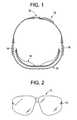
- FIG. 1is a top plan view of an exemplary protective eyewear with adjustable strap in accordance with the present invention
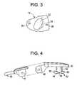
- FIG. 2is a front elevation view of a lens
- FIG. 3is an enlarged view of a slot formed in the lens
- FIG. 4is an exploded enlarged top plan view of a strap holding temple prior to assembly of the protective eyewear with adjustable strap in accordance with the present invention of FIG. 1;
- FIG. 5is an exploded side-elevation view of the strap holding temple of FIG. 4;
- FIG. 6is a partial exploded top plan view of a connective buckle and strap portion of the adjustable strap in accordance with FIG. 1;
- FIG. 7is a partial side elevation view of the connective buckle and strap portion of FIG. 6;
- FIG. 8is a front perspective view of a frame of the device of FIG. 1 prior to assembly
- FIG. 9is a left side view of the frame of FIG. 8;
- FIG. 10is a perspective view of channels formed in the frame
- FIG. 11is an exploded perspective view of the adjustable strap and the strap holding temple of FIGS. 4-6, and the lens of FIG. 2;
- FIG. 12is a perspective view of a slot in the lens of FIG. 2;
- FIG. 13is a front elevation view of another embodiment of the frame of FIG. 8;
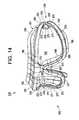
- FIG. 14is a front perspective view of the frame of FIG. 13;
- FIG. 15is a side elevation view of the frame of FIG. 13;
- FIG. 16is a top plan view of the frame of FIG. 13.
- FIG. 17is a bottom plan view of the frame of FIG. 13 .
- the device 10generally includes a lens 12 , a frame 14 , a pair of strap holding temples 16 and 18 and an adjustable strap assembly 20 .
- Lens 12is preferably the unitary, plano lens depicted in FIGS. 13-15 of the aforementioned U.S. Ser. No. 08/641,901.
- lens 12may consist of any other suitable protective lenses (having an alternative shape) including but not limited to the lenses depicted in FIGS. 1-6 and 11 - 12 of U.S. Ser. No. 08/641,901 or the lenses in the aforementioned U.S. Pat. Nos. 4,867,550; 4,741,611; 4,674,851; 4,859,048; 5,381,192 and 5,032,017.
- lens 12is preferably a plano lens wherein the plano lens comprises a front surface curvature which is created by rotating an aspheric shape about an axis which is offset from an axis of the aspheric shape.
- the aspheric shapeis an ellipse or at least is an aspheric shape, a segment of which has an elliptical arc. This elliptical arc is rotated about an axis spaced (offset) some distance from a major or minor axis of the ellipse.
- the ellipseis rotated about an axis spaced from and parallel to the major or minor axis of the ellipse, but in the same plane as the ellipse.
- the resulting surface of this preferred lens configurationwill have a cross-section in the horizontal meridian which is a segment of an ellipse, and a cross-section in the vertical meridian which is a segment of a circle.
- a significant feature of the preferred lens configurationis that the surface generated is rotationally symmetric.
- eyewear made of safety glass or any other suitable materialcan be utilized in conformance with this invention.
- the eyewear of the present inventionallows the user to hold the eyewear securely to the head by means of a unique adjustable strap or to use this adjustable strap to conveniently and securely attach the eyewear to another piece of safety equipment such as noise suppression ear muffs or communication head phones.
- the lens 12includes a slot 22 formed therein which cooperate with an end piece 30 (FIGS. 8-9) to provide adjustment of the pantoscopic angle of the eyewear.
- Slot 22is generally oval shaped and has a center circular area 24 .
- Projections 26are formed on the surface of the lens 12 and extend away from the lens surface. Slot 22 permits lens 12 to be securely coupled to the frame 14 as will be described in greater detail hereinafter.
- FIGS. 1, and 4 - 5show an adjustable strap holding element 40 which is used in the device 10 of the present invention.
- Strap holding element 40includes a temple hinge 42 .
- the temple hinge 42is pivotally coupled to the end piece 30 with a pin 44 inserted through hinge element 46 to form a pivotable joint between end piece 30 and strap holding element 40 .
- the pivotable joint between the end piece 30 and the strap holding element 40allows the temples 14 , 16 to fold one upon the other to enable the eyewear to take up minimum space when eyewear 10 is stored or not in use. This pivotal joint also acts to enhance the fit of the eyewear to the user's head by appropriately conforming the strap and eyewear as required.
- the material used for end piece 30 and strap holding element 40is preferably a suitable moldable plastic.
- strap holding temples 14 , 16are connected directly to the upper, outer edges of the lens 12 .
- the end piece 30includes a post shown generally at 50 including a cylindrical neck 52 and a head 54 .
- the end piece 30includes recesses 56 that engage projections 26 (FIG. 3) formed on the exterior surface of the lens 12 .
- a groove 58is formed in the head 54 and a portion of the neck 52 .
- the groove 58comprises a transverse groove extending across the head 54 .
- the groove 58may have any number of shapes including a v-shape (not shown) where the width of the groove at one end is greater than the width of the groove at the other end. It is therefore understood that alternative geometries may be used for groove 58 .
- the groove 58is formed generally perpendicular to the longitudinal axis of head 54 and extends across the entire head 54 .
- the end piece 30is coupled to the lens 12 by inserting the post 50 through the slot 22 and rotating the end piece 30 .
- the wearerrotates the end piece 30 and aligns one pair of the recesses 56 with the projections 26 formed on the lens 12 .
- the groove 58allows the distal ends 60 and 62 along the longitudinal axis of the head 54 to flex away from the lens 12 . This allows the end piece 30 to rotate within the lens 12 more easily. This is particularly useful when the end piece 30 is first rotated upon insertion of the end piece into the lens 12 and when the pantoscopic angle is adjusted.
- the end piece 30is made from a resilient material and the distal ends 60 and 62 of the head 54 apply pressure to the lens 12 and hold the end piece 30 at the desired pantoscopic angle.
- pantoscopic angle features of the present inventionare preferably identical to the pantascopic angle features of commonly assigned U.S. patent application Ser. No. 08/770,920 filed Dec. 20, 1996 (all of the contents of which are incorporated herein by reference) except that the temple length adjustment housing 70 and temple tip 80 are replaced by the strap holding elements 40 and strap assembly 18 in the present invention. Therefore, reference is made to the application U.S. Ser. No. 08/770,920 for a additional details of the pantoscopic angle feature.
- the pantoscopic adjustment featuresassure for snug and comfortable fit especially when the protective eyewear of the present invention is combined with other safety devices.
- Adjustable strap assembly 20is comprised of a right hand buckle and strap assembly generally shown at 70 and a left hand buckle and strap assembly generally shown at 72 .
- Right hand buckle and strap assembly 70is comprised of a suitable length of strap 74 and a snap-in female portion of buckle 76 .
- left hand buckle assembly 72is comprised of a suitable length of strap 78 , the male portion of snap-in buckle 80 which mates with the female portion of buckle 76 and a known strap tightening fastener 82 for adjusting the left hand strap 78 to the desired position for a secure mounting of the eyewear on a person's head to assure a snug and comfortable fit.
- Strap portion 74 and strap portion 78are suitably sized as is known in the industry and is preferably of known stretchable materials.
- Half buckle 76 and half buckle 80 and strap tightening fastener 82are commercially available and should be of such material and finish as required by the environment where used. Both half buckle 76 and half buckle 80 have known snap connectors that snap into detents that exist on the outside of the safety ear muffs, head phones or any other safety device used in conjunction with the present invention eyewear.
- strap 78is longer than strap 74 because the extra length of strapping is needed to provide adequate adjustment of the adjustable strap assembly 20 . It should be further noted that the end 84 of right hand strap 74 is folded over a loop 86 of buckle (half) 76 and extends a suitable distance and is assembled to a portion of strap 74 by known methods such as adhesives, welding or other known means.
- the frame 14includes opposed sides 90 and 92 and includes opposing ends 91 , 93 .
- Lens 12is retained on side 90 and side 92 forms a part of a skirt member generally indicated at 100 .
- Frame 14includes a plurality of ventilation channels 110 to allow ventilation into the device during use to prevent fogging of lens 12 and to provide comfort for the user.
- a lip 120is provided along portions of the frame 14 to prevent dust and other unwanted particles and liquids from entering the device 10 during use.
- the side 90receives the lens 12 and faces away from the user during use.
- the side 90includes opposed protrusions 122 , 124 disposed at a bridge portion 130 to locate and retain the lens 12 on the side 90 .
- the frame 14includes temple portions 132 , 134 , wherein each of the temple portions 132 , 134 includes an upper and lower protrusion 136 , 138 , respectively which locate the lens 12 on the side 90 and retain the lens 12 by the contact of head portions 54 which face inward over the lens 12 when assembled.
- the frame 14is preferably made of plastic and is resilient for ease of assembly.
- protrusions 122 , 124also include head portions 140 which fit over the lens 12 to assist in a precise fit.
- the frame 14further includes openings 150 , 152 .
- the lip 120is contoured and is disposed along part of an upper portion 154 and a lower portion 157 of the side 90 .
- the lip 120extends outward from the side 90 and tapers to its top 156 .
- the lens 12rests against the lip 120 at its outer periphery along a portion of its top and bottom.
- the plurality of vent channels 110along an inner side 121 of the lip 120 and a surface 97 of the side 90 .
- the ventilation channels 110comprise L-shaped recesses disposed along surface 97 of the side 90 and the inner side 121 of the lip 120 .
- the L-shape of the ventilation channels 110provides indirect ventilation to the face (and eyes) when the device 10 is worn.
- the ventilation channels 110include recessed walls 160 which are separated by divider walls 162 . Similarly, recessed walls 164 are separated by divider walls 166 . Thus, air may enter from the side 90 of the frame 14 when lens 12 is assembled to the frame 14 by entering the ventilation channels 110 at recessed wall 164 and then traveling generally along recessed wall 160 . Thus, ventilation occurs indirectly. In this manner, dust and other particles and liquid substances cannot fall between the lens 12 and the wearer's face because the lip 120 extends beyond the lens 12 . Thus, ventilation is achieved while protection from dust and unwanted particles and liquids is optimized. It will be appreciated to those of ordinary skill in the art that the precise shape of the opening may be varied to allow for indirect ventilation.
- Each temple portion 132 , 134includes an arcuate portion 170 connecting an upper temple portion 172 and a lower temple portion 174 .
- Each temple portion 132 , 134actually defines a temple slot 131 formed in the frame 14 and partially defines by arcuate portion 170 .
- Arcuate body portions 170include inner arcuate surfaces 176 . As described in greater detail hereinafter, inner arcuate surfaces 176 form a detachable attachment together with the head 54 of the end piece 30 on strap assembly 20 .
- head 54As head 54 is turned, it contacts the arcuate surface 176 to force respective ends 13 , 15 of the lens 12 against protrusions 136 , 138 to retain lens 12 onto side 112 by the contact of lens 12 against protrusions 136 , 138 (and respective heads 54 ). This results in lens 12 being better retained in the frame 14 .
- the side 90 of the frame 14further includes an outer perimetric rim 180 which extends around the outer periphery of the side 90 and extends outwardly away from the side 90 so as to provide a raised rim. Accordingly, the raised perimetric rim 180 extends about the lip 120 , the protrusions 122 , 124 , 136 , and 138 and openings 150 , 152 .
- the skirt 100is formed by a beveled surface 182 which extends outwardly from the perimetric rim 180 to a flange element 190 .
- the skirt 100 and the perimetric rim 180serve to define the temple slot 131 which has an arcuate shape at the end defined by the arcuate portion 170 .
- the beveled surface 182extends around the perimetric rim 180 and is preferably integrally formed with the remaining portions of the frame 14 .
- the flange element 190is provided at selected portions of the frame 14 and more specifically, the flange element 190 is provided at locations around the periphery of the frame 14 .
- the flange element 190forms a pair of opposing beveled edges 192 at a location generally below the bridge portion 130 . At this location, the flange element 190 is inverted and extends inwardly away from the side 90 .
- the flange element 190inverts, it forms a nose bridge portion 194 which is designed so that a nose of the user may rest therebetween comfortably.
- the skirt 100provides an effective seal against the face of the user when the device 10 is worn so that undesired foreign matter, including liquid substances, is prevented from entering into the eye area of the user underneath the eyewear being worn. More specifically, the skirt 100 provides an effective seal to help the wearer be protected from liquids and solid matter, e.g., particulate, which accidentally may be directed in a direction toward the eyes of the user.
- liquids and solid mattere.g., particulate
- One particular application of device 10is in a workplace where liquid splashes are possible and potentially damaging for the user of device 10 if the liquid is allowed to contact the eyes of the user. It will also be appreciated that the device 10 of the present invention likewise protects the eyes from solid particles and other foreign matter.
- the skirt 100is preferably formed of the same material as the frame 14 , the skirt 100 is formed of an elastomeric material which provides the desired seal characteristics.
- the frame 14including an integral skirt 100 , may be formed by any number of fabrication processes including a molding process, e.g., injection molding. It being understood that while a one step molding process is the preferred technique to produce device 10 , it is also equally within the scope of the present invention that the device 10 may be produced by forming the frame 14 without skirt 100 and then forming the skirt 100 by a subsequent molding process.
- a frame 200may be used in conjunction with the lens 12 , the pair of strap holding temples 16 and 18 , and the adjustable strap assembly 20 to form a protective eyewear with adjustable strap according to the present invention.
- the frame 200includes opposed sides 290 and 292 and opposing ends 291 and 293 .
- the side 290receives the lens 12 and faces away from the user during use.
- the frame 200includes a bridge portion 230 disposed substantially equidistant from the opposing ends 291 and 293 .
- the bridge portion 230also includes a nasal web 231 which is designed to rest on the nose of the wearer and provide additional wearing comfort to the user.
- the web 231has a curved bottom edge 233 which seats against the nose.
- the web 231is integrally formed with the remaining portions of the frame 200 .
- An opening 250is disposed in the frame 200 between the bridge 230 and the end 291 .
- An opening 252is disposed between the bridge 230 and the end 293 .
- the frame 200further includes an upper portion 254 and a lower portion 257 .
- An upper lip 220is disposed on the upper portion 254 of the frame 200 and extends from the end 291 to the end 293 .
- the upper lip 220is preferably a generally ‘L’ shaped protrusion that initially extends substantially perpendicularly from the side 290 of the frame 200 and then parallel to the side 290 towards the openings 250 and 252 so as to form an upper slot 222 for receiving the lens 12 as discussed herein.
- a lower lip 224opposes the upper lip 220 on the frame 200 .
- the lower lip 224is disposed on the lower portion 257 of the frame 200 and extends from the end 291 to the end 293 .
- the lower lip 224is likewise a generally ‘L’ shaped protrusion that initially extends substantially perpendicularly away from the side 290 of the frame 200 and then turns substantially parallel to the side 290 towards the openings 250 and 252 thus forming a lower slot 226 for receiving the lens 12 as discussed herein.
- the upper and lower slots 222 and 226are lined with a plurality of ventilation channels 210 to allow ventilation into the device during use to prevent fogging of the lens 12 and to provide comfort for the user.
- the ventilation channels 210comprise U-shaped recesses disposed within the upper and lower slots 222 and 226 , respectively.
- the U-shaped channels 210are disposed within the upper slot 222 upon the side 290 and the upper lip 220 .
- the U-shaped channelsare further disposed within the lower slot 226 upon the side 290 and the lower lip 224 .
- the U-shaped channels 210are disposed to abut the lens 12 when installed, as described herein, thus allowing air to enter the eyewear 10 from the side 290 providing ventilation to the face and eyes of the user.
- the individual ventilation channels 210are constructed similarly to the ventilation channels 110 described herein with reference to FIG. 10 and include the recessed walls 160 , 164 and the divider walls 162 , 166 . This construction allows air to ventilate the eyewear indirectly by traveling along the recessed walls 160 , 164 in a U-shaped path around the edge of the lens 12 thereby preventing dust and particulate matter and liquids from directly falling into the eyewear.
- the upper and lower lips 220 and 224are preferably integrally formed as part of the frame 200 and, in an exemplary embodiment, are composed of a resilient thermoplastic material.
- the lens 12is received on the side 290 .
- the edge of the lens 12is received within the upper and lower slots 222 and 226 , respectively, with the lens 12 abutting the U-shaped ventilation channels 210 .
- the lens 12resiliently snaps into place within the upper and lower slots 222 and 226 , respectively, because of the resilient nature of the frame 200 and the lens 12 is retainingly held therein by the upper and lower lips 220 and 224 , respectively.
- Part of the upper lip 220defines a first bridge tab 221 which serves to secure an upper bridge portion of the lens 12 and a portion 235 of the lower lip 224 acts as a second bridge tab for securing a lower bridge portion of the lens 12 when the lens 12 is received within the upper and lower slots 222 , 226 .
- the frame 200further includes a skirt 201 disposed on the side 292 .
- the skirt 201includes the nose bridge portion 194 described herein with reference to FIGS. 8 and 9.
- the nose bridge portion 194is disposed on the skirt 201 beneath the bridge portion 230 of the frame 200 .
- the skirt 201also includes the beveled surface 182 described herein with reference to FIGS. 8 and 9.
- the beveled surface 182is molded integrally about the frame 200 .
- the beveled surface 182is disposed between the upper and lower lips 220 and 224 , respectively, and the flange element 190 taught herein with reference to FIGS. 8 and 9.
- the flange element 190is provided at locations around the periphery of the frame 200 on the skirt 201 and comprises the nose bridge portion 194 beneath the bridge portion 230 .
- the flange element 190forms an effective seal against the face of the user when the present invention is worn so that undesired foreign matter, including liquids and solids, is prevented from entering into the eye area of the user.
- the flange element 190may be composed of a resilient thermoplastic material to better form to the user's face.
- the frame 200further includes temple portions 232 and 234 disposed at the opposing ends 291 and 293 , respectively.
- Each temple portion 232 and 234includes an arcuate portion 270 connecting an upper temple portion 272 and a lower temple portion 274 .
- the temple portions 232 and 234 and arcuate portions 270define a temple slot 231 for receiving the head 54 of the post 50 of the end piece 30 when inserted in the lens 12 during assemblage of the eyewear utilizing the frame 200 .
- the temple slots 231may be a plurality of shapes sufficient for receiving the head 54 including, but not limited to, rectilinear and curvilinear shapes and combinations thereof
- the upper lip 220 and the lower lip 224each terminate at the opposing ends 291 and 293 , respectively.
- the upper lip 220 and the lower lip 224are disposed at the opposing ends 291 and 293 , respectively, so as to define end piece slots 202 and 204 which each receive the end pieces 30 during assembly and use of the eyewear utilizing the frame 200 .
- the upper and lower lips 220 and 224may contain tapperings 205 at the opposing ends 291 and 293 to facilitate reception of the end pieces 30 .
- the temple portions 232 and 234may include scores 206 on the side 290 of the frame 200 to further enhance reception of the end pieces 30 .
- the frame 200may be composed of a resilient thermoplastic material to allow an elastic fit about the lens 12 and to provide comfort for the user while still maintaining sufficient eye protection from particulate matter and other common hazards associated with the use of the protective eyewear.
- the resilient thermoplastic materialmay comprise, for example, polyvinyl chloride (PVC), TPE, TPU, nylon, PCT, etc.
- the present inventiontherefore offers eyewear which is designed to prevent liquids and solid matter, such as dust and other particulate, from contacting the eyes of the wearer.
- the eyewearmay be worn in a multitude of settings and is easy to wear and manufacture.
Landscapes
- Health & Medical Sciences (AREA)
- Ophthalmology & Optometry (AREA)
- Physics & Mathematics (AREA)
- General Health & Medical Sciences (AREA)
- Veterinary Medicine (AREA)
- Vascular Medicine (AREA)
- Life Sciences & Earth Sciences (AREA)
- Animal Behavior & Ethology (AREA)
- Heart & Thoracic Surgery (AREA)
- Public Health (AREA)
- Biomedical Technology (AREA)
- Engineering & Computer Science (AREA)
- Optics & Photonics (AREA)
- General Physics & Mathematics (AREA)
- Otolaryngology (AREA)
- Eyeglasses (AREA)
- Respiratory Apparatuses And Protective Means (AREA)
- Finger-Pressure Massage (AREA)
- Purses, Travelling Bags, Baskets, Or Suitcases (AREA)
- Artificial Filaments (AREA)
- Catching Or Destruction (AREA)
- Farming Of Fish And Shellfish (AREA)
Abstract
Description
Claims (24)
Priority Applications (13)
| Application Number | Priority Date | Filing Date | Title |
|---|---|---|---|
| US09/542,238US6276795B1 (en) | 1996-05-02 | 2000-04-04 | Protective eyewear with adjustable strap |
| EP01964662AEP1189559B1 (en) | 2000-04-04 | 2001-04-03 | Protective eyewear with adjustable strap |
| AU87286/01AAU784002B2 (en) | 2000-04-04 | 2001-04-03 | Protective eyewear with adjustable strap |
| JP2001572024AJP4416370B2 (en) | 2000-04-04 | 2001-04-03 | Safety glasses with adjustable strap |
| PCT/US2001/010787WO2001074277A1 (en) | 2000-04-04 | 2001-04-03 | Protective eyewear with adjustable strap |
| AT01964662TATE300264T1 (en) | 2000-04-04 | 2001-04-03 | SAFETY GLASSES WITH ADJUSTABLE STRAP |
| ES01964662TES2247159T3 (en) | 2000-04-04 | 2001-04-03 | EYE COVER WITH ADJUSTABLE BELT. |
| DE60112203TDE60112203T2 (en) | 2000-04-04 | 2001-04-03 | SAFETY GOGGLES WITH ADJUSTABLE RIBBON |
| BR0105933-5ABR0105933A (en) | 2000-04-04 | 2001-04-03 | Protective glasses with adjustable lanyard |
| MXPA01012472AMXPA01012472A (en) | 2000-04-04 | 2001-04-03 | Protective eyewear with adjustable strap. |
| CA002377390ACA2377390C (en) | 2000-04-04 | 2001-04-03 | Protective eyewear with adjustable strap |
| ZA200109473AZA200109473B (en) | 2000-04-04 | 2001-11-16 | Protective eyewear with adjustable strap. |
| NO20015891ANO20015891L (en) | 2000-04-04 | 2001-12-03 | Protective glasses with adjustable strap |
Applications Claiming Priority (6)
| Application Number | Priority Date | Filing Date | Title |
|---|---|---|---|
| US64190196A | 1996-05-02 | 1996-05-02 | |
| US08/770,920US5909267A (en) | 1996-05-02 | 1996-12-20 | Pantascopic adjustment mechanism for eyewear |
| US08/806,595US6024446A (en) | 1996-05-02 | 1997-02-26 | Eyewear with hingedly attached strapped head retainer |
| US08/806,832US5825455A (en) | 1996-05-02 | 1997-02-26 | Aspheric plano eyewear |
| US09/032,505US6149268A (en) | 1996-05-02 | 1998-02-26 | Protective eyewear with at least one ventilation channel |
| US09/542,238US6276795B1 (en) | 1996-05-02 | 2000-04-04 | Protective eyewear with adjustable strap |
Related Parent Applications (1)
| Application Number | Title | Priority Date | Filing Date |
|---|---|---|---|
| US09/032,505Continuation-In-PartUS6149268A (en) | 1996-05-02 | 1998-02-26 | Protective eyewear with at least one ventilation channel |
Publications (1)
| Publication Number | Publication Date |
|---|---|
| US6276795B1true US6276795B1 (en) | 2001-08-21 |
Family
ID=24162917
Family Applications (1)
| Application Number | Title | Priority Date | Filing Date |
|---|---|---|---|
| US09/542,238Expired - LifetimeUS6276795B1 (en) | 1996-05-02 | 2000-04-04 | Protective eyewear with adjustable strap |
Country Status (13)
| Country | Link |
|---|---|
| US (1) | US6276795B1 (en) |
| EP (1) | EP1189559B1 (en) |
| JP (1) | JP4416370B2 (en) |
| AT (1) | ATE300264T1 (en) |
| AU (1) | AU784002B2 (en) |
| BR (1) | BR0105933A (en) |
| CA (1) | CA2377390C (en) |
| DE (1) | DE60112203T2 (en) |
| ES (1) | ES2247159T3 (en) |
| MX (1) | MXPA01012472A (en) |
| NO (1) | NO20015891L (en) |
| WO (1) | WO2001074277A1 (en) |
| ZA (1) | ZA200109473B (en) |
Cited By (59)
| Publication number | Priority date | Publication date | Assignee | Title |
|---|---|---|---|---|
| USD465507S1 (en) | 2002-02-11 | 2002-11-12 | Bao-Lian Wang | Ski goggles |
| USD466916S1 (en) | 2001-07-05 | 2002-12-10 | Bao-Lian Wang | Goggles |
| US20030140403A1 (en)* | 2002-01-25 | 2003-07-31 | Terry Chou | Lens/frame assembly for swimming goggles |
| US20030233702A1 (en)* | 2002-06-25 | 2003-12-25 | Chih-Lung Chen | Assembly system for securing an adjusting strap to a frame of goggles |
| US6692124B2 (en) | 2002-05-20 | 2004-02-17 | Robert Katz | Eyewear with ventilation |
| US6715157B2 (en) | 2002-08-20 | 2004-04-06 | Spy Optic, Inc. | Sports goggles |
| USD500781S1 (en) | 2003-08-04 | 2005-01-11 | Spy Optic, Inc. | Sunglass |
| USD503422S1 (en) | 2003-10-29 | 2005-03-29 | Bacou-Dalloz Eye & Face Protection, Inc. | Silicone goggle |
| USD508069S1 (en)* | 2003-05-16 | 2005-08-02 | Silhouette International Schmied Ag | Sunglasses with pad |
| US20050206841A1 (en)* | 2004-03-22 | 2005-09-22 | Davin Saderholm | Goggle lens |
| US20050254001A1 (en)* | 2004-05-17 | 2005-11-17 | Warrior Lacrosse, Inc. | Protective eyewear with detachable frame |
| USD511789S1 (en)* | 2003-12-03 | 2005-11-22 | Bacou-Dalloz Eye & Face Protection, Inc. | Goggle clip |
| USD523463S1 (en)* | 2004-05-11 | 2006-06-20 | All-Logic Int. Co., Ltd. | Eyeglass frame with lens |
| USD524355S1 (en)* | 2004-09-15 | 2006-07-04 | Sun Sight Glasses Co., Ltd. | Eyeglasses |
| USD525643S1 (en)* | 2004-06-14 | 2006-07-25 | Body Specs | Eyeglasses |
| USD527752S1 (en)* | 2004-07-20 | 2006-09-05 | Bacou-Dalloz Eye & Face Protection, Inc. | Lens for safety eyewear |
| FR2883160A1 (en)* | 2005-03-18 | 2006-09-22 | Cebe Sa | MASK, IN PARTICULAR FOR THE PRACTICE OF SLIDING SPORTS |
| US20060218705A1 (en)* | 2005-03-30 | 2006-10-05 | Herman Chiang | Swimming goggles |
| US20060272078A1 (en)* | 2004-10-29 | 2006-12-07 | Riccardo Polinelli | Apparatus and methodology to mitigate fogging on dual lens sports goggle |
| USD536018S1 (en)* | 2005-04-29 | 2007-01-30 | Arena Industries, Llc | Goggles |
| USD536361S1 (en)* | 2005-11-09 | 2007-02-06 | Focus Systems Technology Co., Ltd. | Eyeglasses |
| USD557728S1 (en)* | 2004-05-18 | 2007-12-18 | Andreas Helbrecht | Sport safety glasses |
| US7404217B2 (en) | 2004-10-29 | 2008-07-29 | Spy Optic, Inc. | Screen for eye protection goggles and a method of forming a screen |
| US20080189821A1 (en)* | 2007-02-12 | 2008-08-14 | Anderson Kenneth K | Protective mask having removable lens and detachable head strap |
| US20080301857A1 (en)* | 2007-06-06 | 2008-12-11 | Tzu-Feng Wang-Lee | Protective goggles |
| EP2008625A1 (en)* | 2007-06-26 | 2008-12-31 | Jiann Lih Optical., Ltd. | Protective goggles |
| USD588624S1 (en)* | 2007-03-26 | 2009-03-17 | All-Logic Int. Co., Ltd. | Eyewear |
| USD589235S1 (en)* | 2007-10-23 | 2009-03-31 | Bison Designs, Llc | Visor |
| USD601615S1 (en) | 2008-09-25 | 2009-10-06 | Spy Optic, Irc. | Sunglass |
| USD601616S1 (en) | 2008-09-25 | 2009-10-06 | Spy Optic, Inc. | Sunglass |
| USD602977S1 (en) | 2008-08-08 | 2009-10-27 | Sperian Eye & Face Protection Inc. | Safety eyewear |
| USD602978S1 (en) | 2008-09-25 | 2009-10-27 | Spy Optic, Inc, | Sunglass |
| US20100064421A1 (en)* | 2008-09-18 | 2010-03-18 | Tzu-Feng Wang-Lee | Protective Goggle Assembly |
| USD615582S1 (en) | 2009-12-23 | 2010-05-11 | Sperian Eye & Face Protection, Inc. | Safety eyewear |
| US20100229292A1 (en)* | 2009-03-10 | 2010-09-16 | William Tan | Goggle with Quick Release Double Locking Lens |
| USD638050S1 (en) | 2010-03-12 | 2011-05-17 | Orange 21 North America Inc. | Sunglass |
| US20110113536A1 (en)* | 2009-09-17 | 2011-05-19 | Weisel Jonathan E | Goggles position adjustment assemblies and methods |
| US20110139163A1 (en)* | 2009-12-15 | 2011-06-16 | Hillila David J | Vibration apparatus for stimulating paranasal sinuses |
| US8083344B2 (en) | 2005-05-17 | 2011-12-27 | Revision Military Inc. | Protective eyewear including auxiliary lenses |
| US8161578B1 (en)* | 2010-12-19 | 2012-04-24 | Terry Chou | Padding device for swimming/diving goggles |
| USD662693S1 (en) | 2011-03-25 | 2012-07-03 | Jay Becker | Cap with dual-angled visor |
| USD677711S1 (en) | 2011-07-01 | 2013-03-12 | Spy Optic Inc. | Sunglass |
| US8484762B2 (en) | 2011-09-09 | 2013-07-16 | Samuel A. Goldstein | Protective sports headgear |
| USD689118S1 (en) | 2011-07-01 | 2013-09-03 | Spy Optic Inc. | Sunglass |
| USD694313S1 (en) | 2012-06-21 | 2013-11-26 | Spy Optic Inc. | Sunglass |
| USD694314S1 (en) | 2012-04-18 | 2013-11-26 | Spy Optic Inc. | Sunglass |
| USD694312S1 (en) | 2012-04-26 | 2013-11-26 | Spy Optic Inc. | Sunglass |
| US20140250573A1 (en)* | 2013-03-11 | 2014-09-11 | Smith Optics, Inc. | Strap attachment systems and goggles including same |
| US9072331B2 (en) | 2011-01-17 | 2015-07-07 | Smith Optics, Inc. | Goggle attachment system for a helmet |
| US20150202087A1 (en)* | 2014-01-22 | 2015-07-23 | Aswan International Corp. | Goggle |
| US20150290036A1 (en)* | 2014-04-14 | 2015-10-15 | Jiann Lih Optical Co., Ltd. | Goggle Structure |
| USD748716S1 (en)* | 2014-07-29 | 2016-02-02 | All-Logic Int. Co., Ltd | Goggles |
| USD748718S1 (en)* | 2014-08-01 | 2016-02-02 | All-Logic Int. Co., Ltd | Goggles |
| US9256081B2 (en) | 2013-10-11 | 2016-02-09 | Warrior Sports, Inc. | Protective eyewear |
| CN105722671A (en)* | 2013-11-20 | 2016-06-29 | 金伯利-克拉克环球有限公司 | Eyewear containing a porous polymeric material |
| US20170354538A1 (en)* | 2016-06-13 | 2017-12-14 | Arthur Wang | Eyewear component with replaceable lens |
| US20190142639A1 (en)* | 2016-04-25 | 2019-05-16 | Fox Head, Inc. | Attachment system for a lens to goggles |
| US20200146889A1 (en)* | 2018-11-14 | 2020-05-14 | Aswan International Corp. | Goggle device and buckling module thereof |
| US20220226154A1 (en)* | 2021-01-20 | 2022-07-21 | Finis Inc | Swim goggle |
Families Citing this family (8)
| Publication number | Priority date | Publication date | Assignee | Title |
|---|---|---|---|---|
| US20090025715A1 (en)* | 2005-02-24 | 2009-01-29 | Travis Sugden | Breathing Assistance Device |
| JP5418814B2 (en)* | 2009-03-13 | 2014-02-19 | 山本光学株式会社 | goggles |
| US8246166B2 (en)* | 2009-03-16 | 2012-08-21 | Brent Sheldon | Eyewear with reflective head strap |
| US7942520B2 (en) | 2009-03-16 | 2011-05-17 | Brent Sheldon | Eyewear with reflective frame |
| US7828427B2 (en) | 2009-03-16 | 2010-11-09 | Brent Sheldon | Glasses with reflective frame |
| US7942521B2 (en) | 2009-03-16 | 2011-05-17 | Brent Sheldon | Glasses with reflective frames |
| JP5396316B2 (en)* | 2010-03-17 | 2014-01-22 | ミドリ安全株式会社 | goggles |
| US8517533B2 (en) | 2010-12-17 | 2013-08-27 | Mark Razin | Eyewear with removeable secured adjustable strap |
Citations (72)
| Publication number | Priority date | Publication date | Assignee | Title |
|---|---|---|---|---|
| US289740A (en) | 1883-12-04 | Thomas a | ||
| US836599A (en) | 1905-12-05 | 1906-11-20 | Standard Optical Co | Mounting for eyeglasses. |
| US1032488A (en) | 1907-09-06 | 1912-07-16 | Frank A Marcher | Mounting for eyeglasses. |
| US1119811A (en) | 1912-06-19 | 1914-12-08 | American Optical Corp | Lens attachment. |
| US1181365A (en) | 1915-06-29 | 1916-05-02 | Henry F Beaudry | Spectacles or eyeglasses. |
| US1189986A (en) | 1915-09-03 | 1916-07-04 | Fredercik C Merry | Spectacle or eyeglass mounting. |
| US1217035A (en) | 1916-03-13 | 1917-02-20 | Ernest L Mcdowell | Device for fitting eyeglass-lenses. |
| US1250703A (en) | 1915-06-04 | 1917-12-18 | American Optical Corp | Lens-clip. |
| US1274870A (en) | 1916-03-06 | 1918-08-06 | Daniel G Golding | Lens-mounting for eyeglasses. |
| US1278190A (en) | 1915-02-20 | 1918-09-10 | Laurence C Martin | Eyeglass construction. |
| US1294390A (en) | 1917-05-26 | 1919-02-18 | Alfred Burke | Spectacle-temple connection. |
| US2004005A (en) | 1934-03-06 | 1935-06-04 | Michael R Mcdanal | Mounting for rimless spectacles and eyeglasses |
| US2537047A (en) | 1947-11-17 | 1951-01-09 | Ernest B Gatten | Ophthalmic lens for spectacles affording increased field of vision |
| CA485155A (en) | 1952-07-22 | Anthony Baratelli Charles | Ophthalmic device | |
| US2630569A (en) | 1951-06-22 | 1953-03-10 | American Optical Corp | Eye protective device |
| FR1185637A (en) | 1957-10-31 | 1959-08-03 | Improvements to so-called protective glasses | |
| FR1247974A (en) | 1959-10-24 | 1960-12-09 | Vape Sa Ets | Panoramic sunglasses |
| US3218765A (en) | 1962-08-22 | 1965-11-23 | Volk David | Lens generating method |
| US3233250A (en) | 1963-07-16 | 1966-02-08 | Renauld International Inc | Ski shield |
| US3233249A (en) | 1963-07-16 | 1966-02-08 | Renauld Internat Inc | Fisherman's goggle |
| US3283446A (en) | 1965-10-05 | 1966-11-08 | Feinbloom William | Corneal contact lens tool |
| US3394980A (en) | 1964-06-11 | 1968-07-30 | Safemaster Inc | Spectacles with adjustable length temples |
| US3526449A (en) | 1967-11-09 | 1970-09-01 | Ritchard Salvage | One-piece sunglasses |
| US3544204A (en) | 1969-06-12 | 1970-12-01 | Glendale Optical Co Inc | Adjustable temple for safety spectacles |
| US3605116A (en) | 1968-02-27 | 1971-09-20 | Esb Inc | Industrial spectacles |
| US3623800A (en) | 1969-10-16 | 1971-11-30 | David Volk | Ophthalmic lens of changing power |
| US3691565A (en) | 1970-11-25 | 1972-09-19 | Omnitech Inc | Flight deck goggle |
| US3708224A (en) | 1971-05-24 | 1973-01-02 | Textron Inc | Ventilated goggles |
| US3722986A (en) | 1967-10-30 | 1973-03-27 | L Tagnon | High toric power ophthalmic lenses |
| US3907410A (en) | 1973-11-27 | 1975-09-23 | Rex Richmond | Integral vertical plan adjusting mechanism for eye glasses |
| US3950082A (en) | 1973-01-10 | 1976-04-13 | David Volk | Ophthalmic lens for presbyopia and aphakia |
| US4002439A (en) | 1973-01-10 | 1977-01-11 | David Volk | Method of forming an ophthalmic lens for presbyopia and aphakia |
| US4240178A (en) | 1978-02-24 | 1980-12-23 | SM Industrial Company, Limited | Curtain runner |
| USD270165S (en) | 1981-02-25 | 1983-08-16 | Pro-Tec, Inc. | Eyeglasses |
| US4564272A (en) | 1983-03-18 | 1986-01-14 | Rinnooy Kan Edmond A | Eyeglasses with interchangeable parts |
| US4630906A (en) | 1982-05-14 | 1986-12-23 | Carl-Zeiss-Stiftung | Blank for eyeglass lenses having ellipse-like edge curves and means and method for selecting |
| US4670915A (en) | 1986-03-17 | 1987-06-09 | Evans Bradley J | Interchangeable eyeshield |
| US4674851A (en) | 1985-01-11 | 1987-06-23 | Jannard James H | Removable multi-component sunglasses |
| US4683587A (en) | 1985-06-11 | 1987-07-28 | Silverman Michael D | Submersible personal stereo |
| US4741611A (en) | 1981-03-26 | 1988-05-03 | Pro-Tec, Inc. | Eyeglasses adapted for sports and protective use |
| US4786125A (en) | 1983-08-22 | 1988-11-22 | Farrand Optical Co. | Ocular protective apparatus |
| US4810080A (en) | 1987-09-03 | 1989-03-07 | American Optical Corporation | Protective eyewear with removable nosepiece and corrective spectacle |
| US4824233A (en) | 1985-01-11 | 1989-04-25 | Jannard James H | Multi-component sunglasses |
| US4843655A (en) | 1987-12-15 | 1989-07-04 | Alpina Int'l Sport + Optik-Vertriebs-Gmbh | Protective goggles |
| US4859048A (en) | 1985-01-11 | 1989-08-22 | Oakley, Inc. | Cylindrical lens for sunglasses |
| US4867550A (en) | 1985-01-11 | 1989-09-19 | Oakley, Inc. | Toroidal lens for sunglasses |
| US4955706A (en) | 1988-09-30 | 1990-09-11 | Optyl Eyewear Fashion International Corporation | Composite polymeric spectacle parts |
| US4955087A (en) | 1988-09-15 | 1990-09-11 | Richard Perez | Combined visor and sunglasses assembly |
| US4978182A (en) | 1989-10-23 | 1990-12-18 | Kaiser Optical Systems | Laser protection visor with ellipsoidal geometry |
| US4977627A (en) | 1988-10-18 | 1990-12-18 | American Optical Corporation | Protective goggle |
| US5032017A (en) | 1988-07-26 | 1991-07-16 | Etablissements Bolle Georges, Robert Et Maurice | Spectacles comprising means for quickly fitting the side-pieces and the nose-piece |
| US5050981A (en) | 1990-07-24 | 1991-09-24 | Johnson & Johnson Vision Products, Inc. | Lens design method and resulting aspheric lens |
| USD323333S (en) | 1989-08-22 | 1992-01-21 | Oakley, Inc. | Eyeglasses |
| US5208614A (en) | 1990-11-30 | 1993-05-04 | Oakley, Inc. | Concavely indented lenses for eyeware |
| US5235357A (en) | 1990-11-08 | 1993-08-10 | American Optical Corporation | Spectacle lenses having an inside-out conicoidal front surface and method for forming same |
| US5278999A (en) | 1993-02-17 | 1994-01-18 | Ronald Brown | Combined ear and eye protection device |
| US5357292A (en) | 1992-05-26 | 1994-10-18 | Uvex Safety, Llc | Eyeglasses with adjustable temple inclination |
| USD354067S (en) | 1992-05-22 | 1995-01-03 | Carrera Eyewear Corporation | Eyeglasses |
| US5381192A (en) | 1991-08-07 | 1995-01-10 | Uvex Safety, Llc | Protective eyeglasses construction with adjustable temples |
| US5379463A (en) | 1992-07-24 | 1995-01-10 | Hubert Greenway | Facial shield, particularly for protection from the sun |
| US5387949A (en) | 1992-01-29 | 1995-02-07 | Oakley, Inc. | Eyeglass connection device |
| US5418581A (en) | 1993-06-07 | 1995-05-23 | Bausch & Lomb Incorporated | Hinge system for eyewear |
| USD358828S (en) | 1993-09-22 | 1995-05-30 | Oakley, Inc. | Lens and connectors |
| US5426473A (en) | 1993-10-29 | 1995-06-20 | American Allsafe Company | Safety spectacles with temple hinge providing simultaneous adjustment of effective temple length and width between temples |
| US5511251A (en) | 1994-11-03 | 1996-04-30 | Brakas; Yvonne J. | Head strap for sunglasses |
| US5519896A (en) | 1995-04-13 | 1996-05-28 | Ford; Dan E. | Ventilated sport goggles |
| US5526070A (en) | 1994-02-04 | 1996-06-11 | Killer Loop S.P.A. | Nose pad particularly for spectacle frames |
| US5617588A (en) | 1995-03-16 | 1997-04-08 | Uvex Safety, Inc. | Snap together protective goggle construction with toric lens |
| US5659381A (en) | 1993-12-03 | 1997-08-19 | Killer Loop S.P.A. | Engagement device particularly for lenses of eyeglasses |
| US5666663A (en) | 1994-05-13 | 1997-09-16 | Establissements Bolle | Adapter for protective mask for a helmet |
| US5724119A (en) | 1996-07-12 | 1998-03-03 | Howard S. Leight & Associates Inc. | Earmuff-eyeglass combination |
| US6105177A (en)* | 1997-12-26 | 2000-08-22 | Paulson Manufacturing Corp. | Protective goggles |
Family Cites Families (4)
| Publication number | Priority date | Publication date | Assignee | Title |
|---|---|---|---|---|
| US1441786A (en)* | 1920-03-22 | 1923-01-09 | American Optical Corp | Eye protector |
| US2394799A (en)* | 1944-04-24 | 1946-02-12 | Charles E Morley | Ventilated spectacle frame |
| US2654090A (en)* | 1949-06-08 | 1953-10-06 | William R Christensen | Lens ventilation in goggles structure |
| US6024446A (en)* | 1996-05-02 | 2000-02-15 | Cabot Safety Intermediate Corporation | Eyewear with hingedly attached strapped head retainer |
- 2000
- 2000-04-04USUS09/542,238patent/US6276795B1/ennot_activeExpired - Lifetime
- 2001
- 2001-04-03CACA002377390Apatent/CA2377390C/ennot_activeExpired - Fee Related
- 2001-04-03JPJP2001572024Apatent/JP4416370B2/ennot_activeExpired - Fee Related
- 2001-04-03EPEP01964662Apatent/EP1189559B1/ennot_activeExpired - Lifetime
- 2001-04-03WOPCT/US2001/010787patent/WO2001074277A1/enactiveIP Right Grant
- 2001-04-03BRBR0105933-5Apatent/BR0105933A/enactiveSearch and Examination
- 2001-04-03ATAT01964662Tpatent/ATE300264T1/ennot_activeIP Right Cessation
- 2001-04-03ESES01964662Tpatent/ES2247159T3/ennot_activeExpired - Lifetime
- 2001-04-03AUAU87286/01Apatent/AU784002B2/ennot_activeCeased
- 2001-04-03DEDE60112203Tpatent/DE60112203T2/ennot_activeExpired - Lifetime
- 2001-04-03MXMXPA01012472Apatent/MXPA01012472A/enactiveIP Right Grant
- 2001-11-16ZAZA200109473Apatent/ZA200109473B/enunknown
- 2001-12-03NONO20015891Apatent/NO20015891L/ennot_activeApplication Discontinuation
Patent Citations (73)
| Publication number | Priority date | Publication date | Assignee | Title |
|---|---|---|---|---|
| CA485155A (en) | 1952-07-22 | Anthony Baratelli Charles | Ophthalmic device | |
| US289740A (en) | 1883-12-04 | Thomas a | ||
| US836599A (en) | 1905-12-05 | 1906-11-20 | Standard Optical Co | Mounting for eyeglasses. |
| US1032488A (en) | 1907-09-06 | 1912-07-16 | Frank A Marcher | Mounting for eyeglasses. |
| US1119811A (en) | 1912-06-19 | 1914-12-08 | American Optical Corp | Lens attachment. |
| US1278190A (en) | 1915-02-20 | 1918-09-10 | Laurence C Martin | Eyeglass construction. |
| US1250703A (en) | 1915-06-04 | 1917-12-18 | American Optical Corp | Lens-clip. |
| US1181365A (en) | 1915-06-29 | 1916-05-02 | Henry F Beaudry | Spectacles or eyeglasses. |
| US1189986A (en) | 1915-09-03 | 1916-07-04 | Fredercik C Merry | Spectacle or eyeglass mounting. |
| US1274870A (en) | 1916-03-06 | 1918-08-06 | Daniel G Golding | Lens-mounting for eyeglasses. |
| US1217035A (en) | 1916-03-13 | 1917-02-20 | Ernest L Mcdowell | Device for fitting eyeglass-lenses. |
| US1294390A (en) | 1917-05-26 | 1919-02-18 | Alfred Burke | Spectacle-temple connection. |
| US2004005A (en) | 1934-03-06 | 1935-06-04 | Michael R Mcdanal | Mounting for rimless spectacles and eyeglasses |
| US2537047A (en) | 1947-11-17 | 1951-01-09 | Ernest B Gatten | Ophthalmic lens for spectacles affording increased field of vision |
| US2630569A (en) | 1951-06-22 | 1953-03-10 | American Optical Corp | Eye protective device |
| FR1185637A (en) | 1957-10-31 | 1959-08-03 | Improvements to so-called protective glasses | |
| FR1247974A (en) | 1959-10-24 | 1960-12-09 | Vape Sa Ets | Panoramic sunglasses |
| US3218765A (en) | 1962-08-22 | 1965-11-23 | Volk David | Lens generating method |
| US3233250A (en) | 1963-07-16 | 1966-02-08 | Renauld International Inc | Ski shield |
| US3233249A (en) | 1963-07-16 | 1966-02-08 | Renauld Internat Inc | Fisherman's goggle |
| US3394980A (en) | 1964-06-11 | 1968-07-30 | Safemaster Inc | Spectacles with adjustable length temples |
| US3283446A (en) | 1965-10-05 | 1966-11-08 | Feinbloom William | Corneal contact lens tool |
| US3722986A (en) | 1967-10-30 | 1973-03-27 | L Tagnon | High toric power ophthalmic lenses |
| US3526449A (en) | 1967-11-09 | 1970-09-01 | Ritchard Salvage | One-piece sunglasses |
| US3605116A (en) | 1968-02-27 | 1971-09-20 | Esb Inc | Industrial spectacles |
| US3544204A (en) | 1969-06-12 | 1970-12-01 | Glendale Optical Co Inc | Adjustable temple for safety spectacles |
| US3623800A (en) | 1969-10-16 | 1971-11-30 | David Volk | Ophthalmic lens of changing power |
| US3691565A (en) | 1970-11-25 | 1972-09-19 | Omnitech Inc | Flight deck goggle |
| US3708224A (en) | 1971-05-24 | 1973-01-02 | Textron Inc | Ventilated goggles |
| US3950082A (en) | 1973-01-10 | 1976-04-13 | David Volk | Ophthalmic lens for presbyopia and aphakia |
| US4002439A (en) | 1973-01-10 | 1977-01-11 | David Volk | Method of forming an ophthalmic lens for presbyopia and aphakia |
| US3907410A (en) | 1973-11-27 | 1975-09-23 | Rex Richmond | Integral vertical plan adjusting mechanism for eye glasses |
| US4240178A (en) | 1978-02-24 | 1980-12-23 | SM Industrial Company, Limited | Curtain runner |
| USD270165S (en) | 1981-02-25 | 1983-08-16 | Pro-Tec, Inc. | Eyeglasses |
| US4741611A (en) | 1981-03-26 | 1988-05-03 | Pro-Tec, Inc. | Eyeglasses adapted for sports and protective use |
| US4630906A (en) | 1982-05-14 | 1986-12-23 | Carl-Zeiss-Stiftung | Blank for eyeglass lenses having ellipse-like edge curves and means and method for selecting |
| US4564272A (en) | 1983-03-18 | 1986-01-14 | Rinnooy Kan Edmond A | Eyeglasses with interchangeable parts |
| US4786125A (en) | 1983-08-22 | 1988-11-22 | Farrand Optical Co. | Ocular protective apparatus |
| US4674851A (en) | 1985-01-11 | 1987-06-23 | Jannard James H | Removable multi-component sunglasses |
| US4824233A (en) | 1985-01-11 | 1989-04-25 | Jannard James H | Multi-component sunglasses |
| US4859048A (en) | 1985-01-11 | 1989-08-22 | Oakley, Inc. | Cylindrical lens for sunglasses |
| US4867550A (en) | 1985-01-11 | 1989-09-19 | Oakley, Inc. | Toroidal lens for sunglasses |
| US4683587A (en) | 1985-06-11 | 1987-07-28 | Silverman Michael D | Submersible personal stereo |
| US4670915A (en) | 1986-03-17 | 1987-06-09 | Evans Bradley J | Interchangeable eyeshield |
| US4810080A (en) | 1987-09-03 | 1989-03-07 | American Optical Corporation | Protective eyewear with removable nosepiece and corrective spectacle |
| US4843655A (en) | 1987-12-15 | 1989-07-04 | Alpina Int'l Sport + Optik-Vertriebs-Gmbh | Protective goggles |
| US5032017A (en) | 1988-07-26 | 1991-07-16 | Etablissements Bolle Georges, Robert Et Maurice | Spectacles comprising means for quickly fitting the side-pieces and the nose-piece |
| US4955087A (en) | 1988-09-15 | 1990-09-11 | Richard Perez | Combined visor and sunglasses assembly |
| US4955706A (en) | 1988-09-30 | 1990-09-11 | Optyl Eyewear Fashion International Corporation | Composite polymeric spectacle parts |
| US4977627A (en) | 1988-10-18 | 1990-12-18 | American Optical Corporation | Protective goggle |
| USD323333S (en) | 1989-08-22 | 1992-01-21 | Oakley, Inc. | Eyeglasses |
| US4978182A (en) | 1989-10-23 | 1990-12-18 | Kaiser Optical Systems | Laser protection visor with ellipsoidal geometry |
| US5050981A (en) | 1990-07-24 | 1991-09-24 | Johnson & Johnson Vision Products, Inc. | Lens design method and resulting aspheric lens |
| US5235357A (en) | 1990-11-08 | 1993-08-10 | American Optical Corporation | Spectacle lenses having an inside-out conicoidal front surface and method for forming same |
| US5208614A (en) | 1990-11-30 | 1993-05-04 | Oakley, Inc. | Concavely indented lenses for eyeware |
| US5457505A (en) | 1991-08-07 | 1995-10-10 | Uvex Safety, Inc. | Protective eyeglasses construction |
| US5381192A (en) | 1991-08-07 | 1995-01-10 | Uvex Safety, Llc | Protective eyeglasses construction with adjustable temples |
| US5387949A (en) | 1992-01-29 | 1995-02-07 | Oakley, Inc. | Eyeglass connection device |
| USD354067S (en) | 1992-05-22 | 1995-01-03 | Carrera Eyewear Corporation | Eyeglasses |
| US5357292A (en) | 1992-05-26 | 1994-10-18 | Uvex Safety, Llc | Eyeglasses with adjustable temple inclination |
| US5379463A (en) | 1992-07-24 | 1995-01-10 | Hubert Greenway | Facial shield, particularly for protection from the sun |
| US5278999A (en) | 1993-02-17 | 1994-01-18 | Ronald Brown | Combined ear and eye protection device |
| US5418581A (en) | 1993-06-07 | 1995-05-23 | Bausch & Lomb Incorporated | Hinge system for eyewear |
| USD358828S (en) | 1993-09-22 | 1995-05-30 | Oakley, Inc. | Lens and connectors |
| US5426473A (en) | 1993-10-29 | 1995-06-20 | American Allsafe Company | Safety spectacles with temple hinge providing simultaneous adjustment of effective temple length and width between temples |
| US5659381A (en) | 1993-12-03 | 1997-08-19 | Killer Loop S.P.A. | Engagement device particularly for lenses of eyeglasses |
| US5526070A (en) | 1994-02-04 | 1996-06-11 | Killer Loop S.P.A. | Nose pad particularly for spectacle frames |
| US5666663A (en) | 1994-05-13 | 1997-09-16 | Establissements Bolle | Adapter for protective mask for a helmet |
| US5511251A (en) | 1994-11-03 | 1996-04-30 | Brakas; Yvonne J. | Head strap for sunglasses |
| US5617588A (en) | 1995-03-16 | 1997-04-08 | Uvex Safety, Inc. | Snap together protective goggle construction with toric lens |
| US5519896A (en) | 1995-04-13 | 1996-05-28 | Ford; Dan E. | Ventilated sport goggles |
| US5724119A (en) | 1996-07-12 | 1998-03-03 | Howard S. Leight & Associates Inc. | Earmuff-eyeglass combination |
| US6105177A (en)* | 1997-12-26 | 2000-08-22 | Paulson Manufacturing Corp. | Protective goggles |
Cited By (73)
| Publication number | Priority date | Publication date | Assignee | Title |
|---|---|---|---|---|
| USD466916S1 (en) | 2001-07-05 | 2002-12-10 | Bao-Lian Wang | Goggles |
| US20030140403A1 (en)* | 2002-01-25 | 2003-07-31 | Terry Chou | Lens/frame assembly for swimming goggles |
| US6804835B2 (en)* | 2002-01-25 | 2004-10-19 | Terry Chou | Lens/frame assembly for swimming goggles |
| USD465507S1 (en) | 2002-02-11 | 2002-11-12 | Bao-Lian Wang | Ski goggles |
| US6692124B2 (en) | 2002-05-20 | 2004-02-17 | Robert Katz | Eyewear with ventilation |
| US20030233702A1 (en)* | 2002-06-25 | 2003-12-25 | Chih-Lung Chen | Assembly system for securing an adjusting strap to a frame of goggles |
| US6694532B2 (en)* | 2002-06-25 | 2004-02-24 | High Rainbow Ent. Co., Ltd. | Assembly system for securing an adjusting strap to a frame of goggles |
| US6715157B2 (en) | 2002-08-20 | 2004-04-06 | Spy Optic, Inc. | Sports goggles |
| USD508069S1 (en)* | 2003-05-16 | 2005-08-02 | Silhouette International Schmied Ag | Sunglasses with pad |
| USD500781S1 (en) | 2003-08-04 | 2005-01-11 | Spy Optic, Inc. | Sunglass |
| USD503422S1 (en) | 2003-10-29 | 2005-03-29 | Bacou-Dalloz Eye & Face Protection, Inc. | Silicone goggle |
| USD511789S1 (en)* | 2003-12-03 | 2005-11-22 | Bacou-Dalloz Eye & Face Protection, Inc. | Goggle clip |
| US20050206841A1 (en)* | 2004-03-22 | 2005-09-22 | Davin Saderholm | Goggle lens |
| USD523463S1 (en)* | 2004-05-11 | 2006-06-20 | All-Logic Int. Co., Ltd. | Eyeglass frame with lens |
| US7665840B2 (en)* | 2004-05-17 | 2010-02-23 | Warrior Sports, Inc. | Protective eyewear with detachable frame |
| US20050254001A1 (en)* | 2004-05-17 | 2005-11-17 | Warrior Lacrosse, Inc. | Protective eyewear with detachable frame |
| US20080047051A1 (en)* | 2004-05-17 | 2008-02-28 | Warrior Sports, Inc. | Protective eyewear with detachable frame |
| US7322692B2 (en)* | 2004-05-17 | 2008-01-29 | Warrior Lacrosse, Inc. | Protective eyewear with detachable frame |
| USD557728S1 (en)* | 2004-05-18 | 2007-12-18 | Andreas Helbrecht | Sport safety glasses |
| USD525643S1 (en)* | 2004-06-14 | 2006-07-25 | Body Specs | Eyeglasses |
| USD527752S1 (en)* | 2004-07-20 | 2006-09-05 | Bacou-Dalloz Eye & Face Protection, Inc. | Lens for safety eyewear |
| USD524355S1 (en)* | 2004-09-15 | 2006-07-04 | Sun Sight Glasses Co., Ltd. | Eyeglasses |
| US20060272078A1 (en)* | 2004-10-29 | 2006-12-07 | Riccardo Polinelli | Apparatus and methodology to mitigate fogging on dual lens sports goggle |
| US7404217B2 (en) | 2004-10-29 | 2008-07-29 | Spy Optic, Inc. | Screen for eye protection goggles and a method of forming a screen |
| FR2883160A1 (en)* | 2005-03-18 | 2006-09-22 | Cebe Sa | MASK, IN PARTICULAR FOR THE PRACTICE OF SLIDING SPORTS |
| EP1702596A3 (en)* | 2005-03-18 | 2008-10-29 | Cebe | Mask, in particular for sports involving gliding |
| US20060218705A1 (en)* | 2005-03-30 | 2006-10-05 | Herman Chiang | Swimming goggles |
| US7257848B2 (en)* | 2005-03-30 | 2007-08-21 | Herman Chiang | Swimming goggles |
| USD536018S1 (en)* | 2005-04-29 | 2007-01-30 | Arena Industries, Llc | Goggles |
| US8083344B2 (en) | 2005-05-17 | 2011-12-27 | Revision Military Inc. | Protective eyewear including auxiliary lenses |
| USD536361S1 (en)* | 2005-11-09 | 2007-02-06 | Focus Systems Technology Co., Ltd. | Eyeglasses |
| US7895680B2 (en) | 2007-02-12 | 2011-03-01 | Anderson Kenneth K | Protective mask having removable lens and detachable head strap |
| US20080189821A1 (en)* | 2007-02-12 | 2008-08-14 | Anderson Kenneth K | Protective mask having removable lens and detachable head strap |
| USD588624S1 (en)* | 2007-03-26 | 2009-03-17 | All-Logic Int. Co., Ltd. | Eyewear |
| US20080301857A1 (en)* | 2007-06-06 | 2008-12-11 | Tzu-Feng Wang-Lee | Protective goggles |
| US7725959B2 (en)* | 2007-06-06 | 2010-06-01 | Jiann Lih Optical Co., Ltd. | Protective goggles |
| EP2008625A1 (en)* | 2007-06-26 | 2008-12-31 | Jiann Lih Optical., Ltd. | Protective goggles |
| USD589235S1 (en)* | 2007-10-23 | 2009-03-31 | Bison Designs, Llc | Visor |
| USD602977S1 (en) | 2008-08-08 | 2009-10-27 | Sperian Eye & Face Protection Inc. | Safety eyewear |
| US20100064421A1 (en)* | 2008-09-18 | 2010-03-18 | Tzu-Feng Wang-Lee | Protective Goggle Assembly |
| USD601616S1 (en) | 2008-09-25 | 2009-10-06 | Spy Optic, Inc. | Sunglass |
| USD601615S1 (en) | 2008-09-25 | 2009-10-06 | Spy Optic, Irc. | Sunglass |
| USD602978S1 (en) | 2008-09-25 | 2009-10-27 | Spy Optic, Inc, | Sunglass |
| US20100229292A1 (en)* | 2009-03-10 | 2010-09-16 | William Tan | Goggle with Quick Release Double Locking Lens |
| US8166578B2 (en)* | 2009-03-10 | 2012-05-01 | Kingman International Corporation | Goggle with quick release double locking lens |
| US20110113536A1 (en)* | 2009-09-17 | 2011-05-19 | Weisel Jonathan E | Goggles position adjustment assemblies and methods |
| US20110139163A1 (en)* | 2009-12-15 | 2011-06-16 | Hillila David J | Vibration apparatus for stimulating paranasal sinuses |
| USD615582S1 (en) | 2009-12-23 | 2010-05-11 | Sperian Eye & Face Protection, Inc. | Safety eyewear |
| USD638050S1 (en) | 2010-03-12 | 2011-05-17 | Orange 21 North America Inc. | Sunglass |
| US8161578B1 (en)* | 2010-12-19 | 2012-04-24 | Terry Chou | Padding device for swimming/diving goggles |
| US9072331B2 (en) | 2011-01-17 | 2015-07-07 | Smith Optics, Inc. | Goggle attachment system for a helmet |
| USD662693S1 (en) | 2011-03-25 | 2012-07-03 | Jay Becker | Cap with dual-angled visor |
| USD677711S1 (en) | 2011-07-01 | 2013-03-12 | Spy Optic Inc. | Sunglass |
| USD689118S1 (en) | 2011-07-01 | 2013-09-03 | Spy Optic Inc. | Sunglass |
| US8484762B2 (en) | 2011-09-09 | 2013-07-16 | Samuel A. Goldstein | Protective sports headgear |
| USD694314S1 (en) | 2012-04-18 | 2013-11-26 | Spy Optic Inc. | Sunglass |
| USD694312S1 (en) | 2012-04-26 | 2013-11-26 | Spy Optic Inc. | Sunglass |
| USD694313S1 (en) | 2012-06-21 | 2013-11-26 | Spy Optic Inc. | Sunglass |
| US20140250573A1 (en)* | 2013-03-11 | 2014-09-11 | Smith Optics, Inc. | Strap attachment systems and goggles including same |
| US9655783B2 (en)* | 2013-03-11 | 2017-05-23 | Smith Optics, Inc. | Strap attachment systems and goggles including same |
| US9256081B2 (en) | 2013-10-11 | 2016-02-09 | Warrior Sports, Inc. | Protective eyewear |
| CN105722671A (en)* | 2013-11-20 | 2016-06-29 | 金伯利-克拉克环球有限公司 | Eyewear containing a porous polymeric material |
| US20160252747A1 (en)* | 2013-11-20 | 2016-09-01 | Kimberly-Clark Worldwide, Inc. | Eyewear Containing a Porous Polymeric Material |
| US20150202087A1 (en)* | 2014-01-22 | 2015-07-23 | Aswan International Corp. | Goggle |
| US20150290036A1 (en)* | 2014-04-14 | 2015-10-15 | Jiann Lih Optical Co., Ltd. | Goggle Structure |
| US9326893B2 (en)* | 2014-04-14 | 2016-05-03 | Jiann Lih Optical Co., Ltd. | Goggle structure |
| USD748716S1 (en)* | 2014-07-29 | 2016-02-02 | All-Logic Int. Co., Ltd | Goggles |
| USD748718S1 (en)* | 2014-08-01 | 2016-02-02 | All-Logic Int. Co., Ltd | Goggles |
| US20190142639A1 (en)* | 2016-04-25 | 2019-05-16 | Fox Head, Inc. | Attachment system for a lens to goggles |
| US20170354538A1 (en)* | 2016-06-13 | 2017-12-14 | Arthur Wang | Eyewear component with replaceable lens |
| US20200146889A1 (en)* | 2018-11-14 | 2020-05-14 | Aswan International Corp. | Goggle device and buckling module thereof |
| US10722402B2 (en)* | 2018-11-14 | 2020-07-28 | Aswan International Corp. | Goggle device and buckling module thereof |
| US20220226154A1 (en)* | 2021-01-20 | 2022-07-21 | Finis Inc | Swim goggle |
Also Published As
| Publication number | Publication date |
|---|---|
| ATE300264T1 (en) | 2005-08-15 |
| BR0105933A (en) | 2002-03-19 |
| CA2377390C (en) | 2008-11-18 |
| EP1189559B1 (en) | 2005-07-27 |
| NO20015891L (en) | 2002-02-01 |
| MXPA01012472A (en) | 2002-07-30 |
| JP2003528692A (en) | 2003-09-30 |
| AU8728601A (en) | 2001-10-15 |
| CA2377390A1 (en) | 2001-10-11 |
| WO2001074277A1 (en) | 2001-10-11 |
| JP4416370B2 (en) | 2010-02-17 |
| DE60112203D1 (en) | 2005-09-01 |
| EP1189559A1 (en) | 2002-03-27 |
| AU784002B2 (en) | 2006-01-12 |
| ZA200109473B (en) | 2002-06-20 |
| DE60112203T2 (en) | 2006-06-01 |
| ES2247159T3 (en) | 2006-03-01 |
| NO20015891D0 (en) | 2001-12-03 |
Similar Documents
| Publication | Publication Date | Title |
|---|---|---|
| US6276795B1 (en) | Protective eyewear with adjustable strap | |
| US6149268A (en) | Protective eyewear with at least one ventilation channel | |
| US6511177B1 (en) | Protective eyewear with adjustable strap | |
| WO1998038544A9 (en) | Protective eyewear with adjustable strap | |
| CA1178753A (en) | Safety goggle | |
| EP2023872B1 (en) | Eyewear with mask attachment features | |
| US5617588A (en) | Snap together protective goggle construction with toric lens | |
| US7475982B2 (en) | Vapor barrier attachment for eyewear | |
| US5969787A (en) | Eyewear with browbar ventilation and detachable temples | |
| US20200391057A1 (en) | Respirator Mask with Eyewear Interface | |
| US20030123022A1 (en) | Protective eyewear kit | |
| US7743432B2 (en) | Goggle with interchangeable vent accessories | |
| JP3188648B2 (en) | Industrial safety glasses | |
| NZ232496A (en) | Holder for respirator adjustably fastened to eye protection carrier | |
| KR20200081121A (en) | Goggle mask | |
| AU754177B2 (en) | Protective eyewear with adjustable strap | |
| WO2024015118A1 (en) | Dual chambered protective mask and articulating frame insert for forming same | |
| GB2324386A (en) | Goggles with integrally molded frame and face engaging portion |
Legal Events
| Date | Code | Title | Description |
|---|---|---|---|
| AS | Assignment | Owner name:AEARO COMPANY, MASSACHUSETTS Free format text:ASSIGNMENT OF ASSIGNORS INTEREST;ASSIGNORS:HALL, JAMES;SALACE, JOHN E.;DESY, RAOUL;REEL/FRAME:011049/0501;SIGNING DATES FROM 20000410 TO 20000412 | |
| STCF | Information on status: patent grant | Free format text:PATENTED CASE | |
| AS | Assignment | Owner name:BANKERS TRUST COMPANY, NEW YORK Free format text:SECURITY INTEREST;ASSIGNOR:CABOT SAFETY INTERMEDIATE CORPORATION;REEL/FRAME:012075/0227 Effective date:20010713 | |
| AS | Assignment | Owner name:DEUTSCHE BANK AG, NEW YORK BRANCH, NEW YORK Free format text:SECURITY AGREEMENT;ASSIGNOR:CABOT SAFETY INTERMEDIATE CORPORATION;REEL/FRAME:015293/0386 Effective date:20040420 Owner name:DEUTSCHE BANK AG, NEW YORK BRANCH,NEW YORK Free format text:SECURITY AGREEMENT;ASSIGNOR:CABOT SAFETY INTERMEDIATE CORPORATION;REEL/FRAME:015293/0386 Effective date:20040420 | |
| FPAY | Fee payment | Year of fee payment:4 | |
| AS | Assignment | Owner name:CABOT SAFETY INTERMEDIATE CORPORATION, DELAWARE Free format text:ASSIGNMENT OF ASSIGNORS INTEREST;ASSIGNOR:AEARO COMPANY;REEL/FRAME:017344/0716 Effective date:20060315 | |
| AS | Assignment | Owner name:CABOT SAFETY INTERMEDIATE CORPORATION, NORTH CAROL Free format text:RELEASE BY SECURED PARTY;ASSIGNOR:DEUTSCHE BANK TRUST COMPANY AMERICAS (F.K.A. BANKERS TRUST COMPANY);REEL/FRAME:017379/0444 Effective date:20060324 Owner name:CABOT SAFETY INTERMEDIATE CORPORATION, NORTH CAROL Free format text:RELEASE BY SECURED PARTY;ASSIGNOR:DEUTSCHE BANK AG, NEW YORK BRANCH;REEL/FRAME:017379/0367 Effective date:20060324 | |
| AS | Assignment | Owner name:BANK OF AMERICA, N.A., AS SECOND LIEN COLLATERAL A Free format text:SECURITY AGREEMENT;ASSIGNOR:CABOT SAFETY INTERMEDIATE CORPORATION;REEL/FRAME:017435/0764 Effective date:20060324 Owner name:BANK OF AMERICA, N.A., AS FIRST LIEN COLLATERAL AG Free format text:SECURITY AGREEMENT;ASSIGNOR:CABOT SAFETY INTERMEDIATE CORPORATION;REEL/FRAME:017435/0721 Effective date:20060324 | |
| AS | Assignment | Owner name:BANK OF AMERICA, N.A., AS FIRST LIEN COLLATERAL AG Free format text:GRANT OF FIRST LIEN SECURITY INTEREST IN UNITED STATES PATENTS AND TRADEMARKS;ASSIGNOR:CABOT SAFETY INTERMEDIATE CORPORATION;REEL/FRAME:019520/0001 Effective date:20070601 Owner name:CABOT SAFETY INTERMEDIATE CORPORATION, DELAWARE Free format text:RELEASE OF FIRST LIEN SECURITY INTEREST AT REEL/FRAME NO. 17435/0721;ASSIGNOR:BANK OF AMERICA, N.A., AS FIRST LIEN COLLATERAL AGENT;REEL/FRAME:019511/0914 Effective date:20070601 Owner name:CABOT SAFETY INTERMEDIATE CORPORATION,DELAWARE Free format text:RELEASE OF FIRST LIEN SECURITY INTEREST AT REEL/FRAME NO. 17435/0721;ASSIGNOR:BANK OF AMERICA, N.A., AS FIRST LIEN COLLATERAL AGENT;REEL/FRAME:019511/0914 Effective date:20070601 | |
| CC | Certificate of correction | ||
| CC | Certificate of correction | ||
| AS | Assignment | Owner name:CABOT SAFETY INTERMEDIATE CORPORATION, DELAWARE Free format text:RELEASE OF FIRST LIEN SECURITY INTEREST AT REEL/FRAME NO. 19520/0001;ASSIGNOR:BANK OF AMERICA, N.A.;REEL/FRAME:020733/0440 Effective date:20080401 Owner name:CABOT SAFETY INTERMEDIATE CORPORATION, DELAWARE Free format text:RELEASE OF SECOND LIEN SECURITY INTEREST AT REEL/FRAME NO. 17435/0764;ASSIGNOR:BANK OF AMERICA, N.A.;REEL/FRAME:020733/0510 Effective date:20080401 Owner name:CABOT SAFETY INTERMEDIATE CORPORATION,DELAWARE Free format text:RELEASE OF SECOND LIEN SECURITY INTEREST AT REEL/FRAME NO. 17435/0764;ASSIGNOR:BANK OF AMERICA, N.A.;REEL/FRAME:020733/0510 Effective date:20080401 Owner name:CABOT SAFETY INTERMEDIATE CORPORATION,DELAWARE Free format text:RELEASE OF FIRST LIEN SECURITY INTEREST AT REEL/FRAME NO. 19520/0001;ASSIGNOR:BANK OF AMERICA, N.A.;REEL/FRAME:020733/0440 Effective date:20080401 | |
| REFU | Refund | Free format text:REFUND - PAYMENT OF MAINTENANCE FEE, 8TH YEAR, LARGE ENTITY (ORIGINAL EVENT CODE: R1552); ENTITY STATUS OF PATENT OWNER: LARGE ENTITY Free format text:REFUND - 7.5 YR SURCHARGE - LATE PMT W/IN 6 MO, LARGE ENTITY (ORIGINAL EVENT CODE: R1555); ENTITY STATUS OF PATENT OWNER: LARGE ENTITY | |
| FPAY | Fee payment | Year of fee payment:8 | |
| AS | Assignment | Owner name:CABOT SAFETY INTERMEDIATE LLC, DELAWARE Free format text:CHANGE OF NAME;ASSIGNOR:CABOT SAFETY INTERMEDIATE CORPORATION;REEL/FRAME:022773/0051 Effective date:20080926 | |
| AS | Assignment | Owner name:3M INNOVATIVE PROPERTIES COMPANY, MINNESOTA Free format text:ASSIGNMENT OF ASSIGNORS INTEREST;ASSIGNOR:CABOT SAFETY INTERMEDIATE LLC;REEL/FRAME:022835/0681 Effective date:20090514 | |
| FPAY | Fee payment | Year of fee payment:12 |