US6276728B1 - Fitting for use with corrugated tubing - Google Patents
Fitting for use with corrugated tubingDownload PDFInfo
- Publication number
- US6276728B1 US6276728B1US09/349,869US34986999AUS6276728B1US 6276728 B1US6276728 B1US 6276728B1US 34986999 AUS34986999 AUS 34986999AUS 6276728 B1US6276728 B1US 6276728B1
- Authority
- US
- United States
- Prior art keywords
- fitting
- fingers
- centerline
- finger
- corrugated tubing
- Prior art date
- Legal status (The legal status is an assumption and is not a legal conclusion. Google has not performed a legal analysis and makes no representation as to the accuracy of the status listed.)
- Expired - Lifetime
Links
Images


Classifications
- F—MECHANICAL ENGINEERING; LIGHTING; HEATING; WEAPONS; BLASTING
- F16—ENGINEERING ELEMENTS AND UNITS; GENERAL MEASURES FOR PRODUCING AND MAINTAINING EFFECTIVE FUNCTIONING OF MACHINES OR INSTALLATIONS; THERMAL INSULATION IN GENERAL
- F16L—PIPES; JOINTS OR FITTINGS FOR PIPES; SUPPORTS FOR PIPES, CABLES OR PROTECTIVE TUBING; MEANS FOR THERMAL INSULATION IN GENERAL
- F16L25/00—Construction or details of pipe joints not provided for in, or of interest apart from, groups F16L13/00 - F16L23/00
- F16L25/0036—Joints for corrugated pipes
- Y—GENERAL TAGGING OF NEW TECHNOLOGICAL DEVELOPMENTS; GENERAL TAGGING OF CROSS-SECTIONAL TECHNOLOGIES SPANNING OVER SEVERAL SECTIONS OF THE IPC; TECHNICAL SUBJECTS COVERED BY FORMER USPC CROSS-REFERENCE ART COLLECTIONS [XRACs] AND DIGESTS
- Y10—TECHNICAL SUBJECTS COVERED BY FORMER USPC
- Y10S—TECHNICAL SUBJECTS COVERED BY FORMER USPC CROSS-REFERENCE ART COLLECTIONS [XRACs] AND DIGESTS
- Y10S285/00—Pipe joints or couplings
- Y10S285/903—Corrugated
Definitions
- the flexible gas piping (FGP) systemalso referred to as corrugated stainless steel tubing (CSST) and formerly Interior Gas Piping (IGP) was developed in Japan and first introduced into that market by Osaka Gas and Tokyo Gas Companies during the early 1980's.
- the systemutilizes stainless steel corrugated tubing supplied in rolls or coils with field attachable fittings to distribute gas from a central supply point such as the meter or regulator to the various appliances within a house or building.
- the technologywhich has likened the process of plumbing a house for gas to wiring a house for electricity, substantially reduces installation time and hence the associated higher cost of labor.
- the second fitting introduced into the fieldused first a specialized tool to flatten the convolutions at the end of the CSST tube where the fitting was to be attached and then a second tool was used to put a single flare on the tube end.
- This productis now off the market due to failures in the tubing caused by work hardening of the stainless steel in the flattening and flaring process.
- the third type of fittingwas introduced into the field using no special tools to make a metal to metal seal by folding the convolutions of the tube back on itself creating a double flare. After a limited time in the field it was realized that this fitting design was inconsistent in making a leak tight seal.
- the remedy to the problemwas to design an insert type flaring tool; this was used for about three years. A second redesign was conducted, upgrading the insert tool to a socket type flaring tool.
- a current problem in installing certain fittingsis the number of loose parts that the installer must assemble in the field.
- a typical fittingthere is a body, a nut, a gasket and two split ring washers that must be assembled to couple the fitting to the corrugated tubing.
- This number of partsleads to several disadvantages including complicated assembly and the need to carry extra parts to compensate for lost or damaged parts.
- the fittingincludes a first body having a first internal conduit therethrough and a first centerline.
- the first bodyhas a plurality of fingers integral with the first body. The fingers are positioned radially about a periphery of the first body and each of the fingers is separated from an adjacent finger by a space.
- a second body which mates with the first bodyhas a second internal conduit therethrough and a second centerline. The second body has a finger deflection surface for contacting the fingers and directing the fingers towards the first centerline.
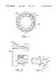
- FIG. 1is a front view of a first body
- FIG. 2is a side view, in partial cross-section, of the first body
- FIG. 3is a cross-sectional view of a portion of FIG. 2;
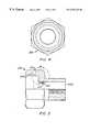
- FIG. 4is a front view of a second body
- FIG. 5is a side view, in partial cross-section, of the second body
- FIG. 6is a cross-sectional view of a portion of FIG. 5;
- FIG. 7is a perspective view of a locating sleeve
- FIG. 8is a side view of the locating sleeve
- FIG. 9is a side view, in partial cross section, of the first body partially engaging the second body.
- FIG. 10is a side view, in partial cross section, of the first body fully engaging the second body.
- FIG. 1is an end view of a first body 100 and FIG. 2 is a side view, in partial cross-section, of the first body 100 .
- First body 100includes a central conduit 102 and external threads 104 for engaging threads on second body 200 .
- Formed integral with first body 100are a plurality of fingers 110 arranged radially about the first body 100 . Adjacent fingers 110 are separated by a space 112 .
- FIG. 3is an enlarged, cross sectional view of a finger 110 .
- Finger 110includes an outside surface 114 , an inside surface 116 and a front face 118 .
- the outside diameter of threads 104is greater than the outside diameter of fingers 110 .
- the finger 110has a varying thickness from front face 118 to the base 120 where finger 110 joins the remainder of first body 100 .
- the finger 110is thickest at front face 118 and the thickness decreases as the inside surface 116 approaches the base 120 .
- the inside surface 116is at an angle a relative to outside surface 114 and relative to the centerline of first body 100 . In an exemplary embodiment, a is 40 degrees.
- a finger stop surface 122is provided on the inside of body 100 opposite inside surface 116 . As described herein, finger 110 is bent inwards towards the centerline of body 100 during installation.
- the finger stop surface 122serves to stop deflection of finger 110 beyond a certain point.
- the finger stop surface 122is at angle ⁇ relative to inside surface 116 . In an exemplary embodiment, ⁇ is 30 degrees.
- each finger 110is trapezoidal.
- the base of the trapezoidis located towards the outside of the body 100 .
- the base of the trapezoidal front face 118contacts the base of the front face of an adjacent finger. This creates a continuous ring to provide a sealing surface as described herein.
- FIG. 4is an end view of a second body 200 and FIG. 5 is a side view, in partial cross-section, of the second body 200 .
- Second body 200includes a central conduit 202 which communicates with conduit 102 to allow gas to travel through the fitting.
- Second body 200includes internal threads 204 that engage external threads 104 on first body 100 .
- the inside surface of second body 200includes a finger deflection surface 206 and a sealing surface 208 .
- the finger deflection surface 206is frusto-conical and is at an angle ⁇ relative to the centerline of second body 200 . In an exemplary embodiment, ⁇ is 15 degrees.
- the finger deflection surface 206has a largest inner diameter greater then the outer diameter of fingers 210 .
- the internal threads 204have an inside diameter greater than the largest inside diameter of finger deflection surface 206 .
- the finger deflection surface 206contacts finger 110 and deflects the fingers 110 towards the centerline of first body 100 .
- Sealing surface 208is used to seal the corrugated tubing as described herein with reference to FIGS. 9-11. Sealing surface 208 is at an angle ⁇ relative to a normal to the centerline of the second body 200 . In an exemplary embodiment, ⁇ is 15 degrees.
- Second body 200also includes a shoulder 212 which is formed by an area of increased diameter 210 in central conduit 202 .
- the shoulder 212serves as a stop to position a locating sleeve 300 (FIGS. 7 and 8) relative to second body 200 .
- the locating sleeveis similar to that disclosed in U.S. Pat. No. 5,799,989, the contents of which are incorporated herein by reference, and pending application Ser. No. 08/905,373, the contents of which are incorporated herein by reference.
- the locating sleeve 300is press fit into second body 200 .
- the locating sleeve 300may be formed integral with second body 200 .
- the locating sleeve 300is generally cylindrical, and may include a tapered section to facilitate insertion. As described herein, the locating sleeve helps to position the corrugated tubing upon installation of the fitting.
- the first body 100 and second body 200may be partially joined by mating threads 104 with threads 204 .
- the corrugated tubing 400is cut in a valley and is snapped into the first body 100 so that fingers 110 are positioned in the first valley adjacent to the cut end of the tubing 400 .
- the smallest inner diameter of the fingers 110is less than the outer diameter of peaks on the corrugated tubing but greater than the outer diameter of the valleys of the corrugated tubing. Accordingly, when the corrugated tubing 400 is inserted in first body 100 , a peak of the corrugated tubing 400 engages the fingers 110 .
- the fingers 110are resilient and spread outward slightly to allow the peak on the corrugated tubing to clear the fingers 110 . Once the peak of the tubing 400 clears the fingers 110 , the fingers 110 return to their original position and rest in a valley of the tubing. This interference between fingers 110 and the tubing 400 secures first body 100 to the tubing 400 .
- the outer diameter of the threads 104 and corresponding inner diameter of threads 204provides a clearance 240 between the threads 204 and the fingers 110 .
- This clearanceallows the fingers 110 to deflect away from the centerline of the first body 100 without interference from the second body 200 .
- the second stepis to create a seal by rotating the second body 200 relative to the first body 100 thereby drawing the first body 100 into second body 200 .
- first body 100enters second body 200
- the outside surface 116 of fingers 110engage finger deflection surface 206 .
- the fingers 110travel along finger deflection surface 206
- the fingers 110are deflected inwards toward the corrugated tubing 400 .
- Locating sleeve 300also enters the tubing 400 to locate the tubing 400 relative to the second body 200 .
- the first body 100 and second body 200continue to be tightened until a seal is achieved as shown in FIG. 10 .
- the fingers 110have been deflected inwards and two layers of corrugated tubing 400 are compressed between the front face 118 of each finger 110 and the sealing surface 208 .
- the two layers of tubing, or double flare,provides a metal-to-metal seal that prevents leakage.
Landscapes
- Engineering & Computer Science (AREA)
- General Engineering & Computer Science (AREA)
- Mechanical Engineering (AREA)
- Quick-Acting Or Multi-Walled Pipe Joints (AREA)
- Gasket Seals (AREA)
- Mutual Connection Of Rods And Tubes (AREA)
- Joints Allowing Movement (AREA)
- Installation Of Indoor Wiring (AREA)
- Joints That Cut Off Fluids, And Hose Joints (AREA)
- Details Of Indoor Wiring (AREA)
- Pipe Accessories (AREA)
Abstract
Description
The flexible gas piping (FGP) system, also referred to as corrugated stainless steel tubing (CSST) and formerly Interior Gas Piping (IGP) was developed in Japan and first introduced into that market by Osaka Gas and Tokyo Gas Companies during the early 1980's. The system utilizes stainless steel corrugated tubing supplied in rolls or coils with field attachable fittings to distribute gas from a central supply point such as the meter or regulator to the various appliances within a house or building. The technology, which has likened the process of plumbing a house for gas to wiring a house for electricity, substantially reduces installation time and hence the associated higher cost of labor. The technology was brought to the United States by the Gas Research Institute who saw it as a means of making gas installations more competitive; thereby increasing the percentage of new construction plumbed for gas and increasing the overall consumption of natural gas on a national basis. The technology was enthusiastically endorsed and supported by major gas utilities who had seen the significant higher cost of installed piping as their single greatest obstacle to selling more gas. Code acceptance required more time and effort to obtain, but the product is now recognized by all national model codes and ANSI, the National Fire Protection Association/National Fuel Gas Code and is tested and recognized by the American Gas Association. This product will eventually supplant black-iron pipe which accounts for approximately 80% of all fuel gas piping today, as well as copper tube which, while enjoying many of the same advantages of FGP, is being banned from this application at an increasing rate.
There have been three types of fittings originally put into the field. The first fitting introduced into the field used a fiber gasket to make the seal and no special tools were needed to assemble this fitting. This fitting has a higher incidence of leaks than the flared metal to metal seals used by other manufacturers.
The second fitting introduced into the field used first a specialized tool to flatten the convolutions at the end of the CSST tube where the fitting was to be attached and then a second tool was used to put a single flare on the tube end. This product is now off the market due to failures in the tubing caused by work hardening of the stainless steel in the flattening and flaring process.
The third type of fitting was introduced into the field using no special tools to make a metal to metal seal by folding the convolutions of the tube back on itself creating a double flare. After a limited time in the field it was realized that this fitting design was inconsistent in making a leak tight seal. The remedy to the problem was to design an insert type flaring tool; this was used for about three years. A second redesign was conducted, upgrading the insert tool to a socket type flaring tool.
A current problem in installing certain fittings is the number of loose parts that the installer must assemble in the field. In a typical fitting, there is a body, a nut, a gasket and two split ring washers that must be assembled to couple the fitting to the corrugated tubing. This number of parts leads to several disadvantages including complicated assembly and the need to carry extra parts to compensate for lost or damaged parts.
The above-discussed and other drawbacks and deficiencies of the prior art are overcome or alleviated by the fitting of the present invention. The fitting includes a first body having a first internal conduit therethrough and a first centerline. The first body has a plurality of fingers integral with the first body. The fingers are positioned radially about a periphery of the first body and each of the fingers is separated from an adjacent finger by a space. A second body which mates with the first body has a second internal conduit therethrough and a second centerline. The second body has a finger deflection surface for contacting the fingers and directing the fingers towards the first centerline.
The above-discussed and other features and advantages of the present invention will be appreciated and understood by those skilled in the art from the following detailed description and drawings.
Referring now to the drawings wherein like elements are numbered alike in the several FIGURES:
FIG. 1 is a front view of a first body;
FIG. 2 is a side view, in partial cross-section, of the first body;
FIG. 3 is a cross-sectional view of a portion of FIG. 2;
FIG. 4 is a front view of a second body;
FIG. 5 is a side view, in partial cross-section, of the second body;
FIG. 6 is a cross-sectional view of a portion of FIG. 5;
FIG. 7 is a perspective view of a locating sleeve;
FIG. 8 is a side view of the locating sleeve;
FIG. 9 is a side view, in partial cross section, of the first body partially engaging the second body; and
FIG. 10 is a side view, in partial cross section, of the first body fully engaging the second body.
The fitting of the present invention is made up of a first body and a second body. FIG. 1 is an end view of afirst body 100 and FIG. 2 is a side view, in partial cross-section, of thefirst body 100.First body 100 includes acentral conduit 102 andexternal threads 104 for engaging threads onsecond body 200. Formed integral withfirst body 100 are a plurality offingers 110 arranged radially about thefirst body 100.Adjacent fingers 110 are separated by aspace 112. FIG. 3 is an enlarged, cross sectional view of afinger 110.Finger 110 includes anoutside surface 114, aninside surface 116 and afront face 118. The outside diameter ofthreads 104 is greater than the outside diameter offingers 110.
Thefinger 110 has a varying thickness fromfront face 118 to the base120 wherefinger 110 joins the remainder offirst body 100. Thefinger 110 is thickest atfront face 118 and the thickness decreases as theinside surface 116 approaches the base120. Theinside surface 116 is at an angle a relative tooutside surface 114 and relative to the centerline offirst body 100. In an exemplary embodiment, a is40 degrees. Afinger stop surface 122 is provided on the inside ofbody 100 opposite insidesurface 116. As described herein,finger 110 is bent inwards towards the centerline ofbody 100 during installation. Thefinger stop surface 122 serves to stop deflection offinger 110 beyond a certain point. Thefinger stop surface 122 is at angle β relative to insidesurface 116. In an exemplary embodiment, β is 30 degrees.
As shown in FIG. 1, thefront face 118 of eachfinger 110 is trapezoidal. The base of the trapezoid is located towards the outside of thebody 100. When thefingers 110 are deflected inwards during installation, the base of thetrapezoidal front face 118 contacts the base of the front face of an adjacent finger. This creates a continuous ring to provide a sealing surface as described herein.
FIG. 4 is an end view of asecond body 200 and FIG. 5 is a side view, in partial cross-section, of thesecond body 200.Second body 200 includes acentral conduit 202 which communicates withconduit 102 to allow gas to travel through the fitting.Second body 200 includesinternal threads 204 that engageexternal threads 104 onfirst body 100. The inside surface ofsecond body 200 includes afinger deflection surface 206 and a sealingsurface 208. As shown in FIG. 6, thefinger deflection surface 206 is frusto-conical and is at an angle γ relative to the centerline ofsecond body 200. In an exemplary embodiment, γ is15 degrees. Thefinger deflection surface 206 has a largest inner diameter greater then the outer diameter offingers 210. Theinternal threads 204 have an inside diameter greater than the largest inside diameter offinger deflection surface 206. Thefinger deflection surface 206contacts finger 110 and deflects thefingers 110 towards the centerline offirst body 100. Sealingsurface 208 is used to seal the corrugated tubing as described herein with reference to FIGS. 9-11. Sealingsurface 208 is at an angle Δ relative to a normal to the centerline of thesecond body 200. In an exemplary embodiment, Δ is 15 degrees.
Installation of the fitting will now be described with reference to FIGS. 9-10. As shown in FIG. 9, thefirst body 100 andsecond body 200 may be partially joined bymating threads 104 withthreads 204. Thecorrugated tubing 400 is cut in a valley and is snapped into thefirst body 100 so thatfingers 110 are positioned in the first valley adjacent to the cut end of thetubing 400. The smallest inner diameter of thefingers 110 is less than the outer diameter of peaks on the corrugated tubing but greater than the outer diameter of the valleys of the corrugated tubing. Accordingly, when thecorrugated tubing 400 is inserted infirst body 100, a peak of thecorrugated tubing 400 engages thefingers 110. Thefingers 110 are resilient and spread outward slightly to allow the peak on the corrugated tubing to clear thefingers 110. Once the peak of thetubing 400 clears thefingers 110, thefingers 110 return to their original position and rest in a valley of the tubing. This interference betweenfingers 110 and thetubing 400 securesfirst body 100 to thetubing 400.
The outer diameter of thethreads 104 and corresponding inner diameter ofthreads 204 provides aclearance 240 between thethreads 204 and thefingers 110. This clearance allows thefingers 110 to deflect away from the centerline of thefirst body 100 without interference from thesecond body 200. This allows thefirst body 100 andsecond body 200 to be partially engaged when thecorrugated tubing 400 is snapped into thefirst body 100. This facilitates installation in that thefirst body 100 is partially engaged withsecond body 200 providing the installer with a single component.
The second step is to create a seal by rotating thesecond body 200 relative to thefirst body 100 thereby drawing thefirst body 100 intosecond body 200. Asfirst body 100 enterssecond body 200, theoutside surface 116 offingers 110 engagefinger deflection surface 206. As thefingers 110 travel alongfinger deflection surface 206, thefingers 110 are deflected inwards toward thecorrugated tubing 400. Locatingsleeve 300 also enters thetubing 400 to locate thetubing 400 relative to thesecond body 200.
Thefirst body 100 andsecond body 200 continue to be tightened until a seal is achieved as shown in FIG.10. Thefingers 110 have been deflected inwards and two layers ofcorrugated tubing 400 are compressed between thefront face 118 of eachfinger 110 and the sealingsurface 208. The two layers of tubing, or double flare, provides a metal-to-metal seal that prevents leakage.
While preferred embodiments have been shown and described, various modifications and substitutions may be made thereto without departing from the spirit and scope of the invention. Accordingly, it is to be understood that the present invention has been described by way of illustration and not limitation.
Claims (40)
1. A fitting for use with corrugated tubing, said fitting comprising:
a first body having an first internal conduit therethrough and a first centerline, said first body including a plurality of fingers integral with said first body, said fingers positioned radially about a periphery of said first body, each of said fingers being separated from an adjacent finger by a space, said first body having first threads; and
a second body which mates with said first body, said second body having a second internal conduit therethrough and a second centerline, said second body having a finger deflection surface for contacting said fingers and directing said fingers towards said first centerline, said second body having second threads for engaging said first threads to couple said first body and said second body.
2. The fitting of claim1 wherein:
said fingers have an inner diameter less than a maximum outer diameter of the corrugated tubing.
3. The fitting of claim1 wherein:
said finger deflection surface is a frusto-conical surface at a third angle relative to said second centerline.
4. The fitting of claim1 wherein:
said second body includes a sealing surface, each of said fingers and said sealing surface compressing said corrugated tubing.
5. The fitting of claim4 wherein:
said sealing surface is at a fourth angle relative to a normal of said second centerline.
6. The fitting of claim5 wherein:
said finger deflection surface is a frusto-conical surface at a third angle relative to said second centerline; and,
said third angle equals said fourth angle.
7. The fitting of claim1 wherein:
each of said fingers has an outside surface and an inside surface, said inside surface being at a first angle relative to said first centerline.
8. The fitting of claim7 wherein:
each of said fingers has a base at the junction between said finger and a remainder of said first body and a front face,
a thickness of each of said fingers varying from said front face to said base.
9. The fitting of claim7 wherein:
said body includes a finger stop surface positioned opposite said inside surface, said finger stop surface being at a second angle relative to said inside surface.
10. The fitting of claim1 further comprising:
a locating sleeve connected to said second body for entering the corrugated tubing and aligning said second body with said corrugated tubing.
11. The fitting of claim1 further comprising:
a locating sleeve connected to said second body for entering the corrugated tubing and aligning said second body with said corrugated tubing.
12. The fitting of claim2 wherein:
said locating sleeve is press fit in said second body.
13. A fitting for use with corrugated tubing, said fitting comprising:
a first body having an first internal conduit therethrough and a first centerline, said first body including a plurality of fingers integral with said first body, said fingers positioned radially about a periphery of said first body, each of said fingers being separated from an adjacent finger by a space; and
a second body which mates with said first body, said second body having a second internal conduit therethrough and a second centerline, said second body having a finger deflection surface for contacting said fingers and directing said fingers towards said first centerline wherein:
each of said fingers has an outside surface and an inside surface, said inside surface being at a first angle relative to said first centerline.
14. The fitting of claim2 wherein:
each of said fingers has a base at the junction between said finger and a remainder of said first body and a front face,
a thickness of each of said fingers varying from said front face to said base.
15. The fitting of claim13 wherein:
said body includes a finger stop surface positioned opposite said inside surface, said finger stop surface being at a second angle relative to said inside surface.
16. The fitting of claim2 wherein:
said fingers have an inner diameter less than a maximum outer diameter of the corrugated tubing.
17. The fitting of claim2 further comprising:
a locating sleeve connected to said second body for entering the corrugated tubing and aligning said second body with said corrugated tubing.
18. The fitting of claim17 wherein:
said locating sleeve is press fit in said second body.
19. The fitting of claim2 wherein:
said finger deflection surface is a frusto-conical surface at a third angle relative to said second centerline.
20. The fitting of claim2 wherein:
said second body includes a sealing surface, each of said fingers and said sealing surface compressing said corrugated tubing.
21. The fitting of claim20 wherein:
said sealing surface is at a fourth angle relative to a normal of said second centerline.
22. The fitting of claim21 wherein:
said finger deflection surface is a frusto-conical surface at a third angle relative to said second centerline; and,
said third angle equals said fourth angle.
23. A fitting for use with corrugated tubing, said fitting comprising:
a first body having an first internal conduit therethrough and a first centerline, said first body including a plurality of fingers integral with said first body, said fingers positioned radially about a periphery of said first body, each of said fingers being separated from an adjacent finger by a space; and
a second body which mates with said first body, said second body having a second internal conduit therethrough and a second centerline, said second body having a finger deflection surface for contacting said fingers and directing said fingers towards said first centerline; and,
a locating sleeve connected to said second body for entering the corrugated tubing and aligning said second body with said corrugated tubing.
24. The fitting of claim6 wherein:
said locating sleeve is press fit in said second body.
25. The fitting of claim23 wherein:
each of said fingers has an outside surface and an inside surface, said inside surface being at a first angle relative to said first centerline.
26. The fitting of claim25 wherein:
each of said fingers has a base at the junction between said finger and a remainder of said first body and a front face,
a thickness of each of said fingers varying from said front face to said base.
27. The fitting of claim23 wherein:
said fingers have an inner diameter less than a maximum outer diameter of the corrugated tubing.
28. The fitting of claim23 wherein:
said body includes a fitting stop surface positioned opposite said inside surface, said finger stop surface being at a second angle relative to said inside surface.
29. The fitting of claim23 wherein:
said finger deflection surface is a frusto-conical surface at a third angle relative to said second centerline.
30. The fitting of claim wherein:
said second body includes a sealing surface, each of said fingers and said sealing surface compressing said corrugated tubing.
31. The fitting of claim30 wherein:
said sealing surface is at a fourth angle relative to a normal of said second centerline.
32. The fitting of claim31 wherein:
said finger deflection surface is a frusto-conical surface at a third angle relative to said second centerline; and,
said third angle equals said fourth angle.
33. A fitting for use with corrugated tubing, said fitting comprising:
a first body having an first internal conduit therethrough and a first centerline, said first body including a plurality of fingers integral with said first body, said fingers positioned radially about a periphery of said first body, each of said fingers being separated from an adjacent finger by a space; and
a second body which mates with said first body, said second body having a second internal conduit therethrough and a second centerline, said second body having a finger deflection surface for contacting said fingers and directing said fingers towards said first centerline;
wherein said second body includes a sealing surface, each of said fingers and said sealing surface compressing said corrugated tubing and,
said sealing surface is at a fourth angle relative to a normal of said second centerline.
34. The fitting of claim33 wherein:
said finger deflection surface is a frusto-conical surface at a third angle relative to said second centerline; and,
said third angle equals said fourth angle.
35. The fitting of claim33 wherein:
each of said fingers has an outside surface and an inside surface, said inside surface being at a first angle relative to said first centerline.
36. The fitting of claim35 wherein:
each of said fingers has a base at the junction between said finger and a remainder of said first body and a front face,
a thickness of each of said fingers varying from said front face to said base.
37. The fitting of claim35 wherein:
said body includes a fitting stop surface positioned opposite said inside surface, said finger stop surface being at a second angle relative to said inside surface.
38. The fitting of claim33 wherein:
said fingers have an inner diameter less than a maximum outer diameter of the corrugated tubing.
39. The fitting of claim33 further comprising:
a locating sleeve connected to said second body for entering the corrugated tubing and aligning said second body with said corrugated tubing.
40. The fitting of claim9 wherein:
said finger deflection surface is a frusto-conical surface at a third angle relative to said second centerline.
Priority Applications (16)
| Application Number | Priority Date | Filing Date | Title |
|---|---|---|---|
| US09/349,869US6276728B1 (en) | 1999-07-08 | 1999-07-08 | Fitting for use with corrugated tubing |
| ZA200001588AZA200001588B (en) | 1999-07-08 | 2000-03-29 | Fitting for use with corrugated tubing. |
| BR0001129-0ABR0001129A (en) | 1999-07-08 | 2000-04-05 | Connection for use with spiral tubes |
| CO00026793ACO5241339A1 (en) | 1999-07-08 | 2000-04-12 | ACCESSORY FOR USE IN ONDULATED PIPING |
| CA002306616ACA2306616C (en) | 1999-07-08 | 2000-04-26 | Fitting for use with corrugated tubing |
| CNB001081756ACN1172105C (en) | 1999-07-08 | 2000-04-26 | Fittings for bellows |
| BR8001223-0UBR8001223U (en) | 1999-07-08 | 2000-06-20 | Connection for use with spiral tubes |
| ES00305554TES2240016T3 (en) | 1999-07-08 | 2000-06-30 | CONNECTOR FOR USE WITH WAVE PIPE. |
| AT00305554TATE293227T1 (en) | 1999-07-08 | 2000-06-30 | FITTING FOR CORRUGATED PIPES |
| PT00305554TPT1072835E (en) | 1999-07-08 | 2000-06-30 | PIPE TO BE USED WITH PIPING |
| EP00305554AEP1072835B1 (en) | 1999-07-08 | 2000-06-30 | Fitting for use with corrugated tubing |
| DE60019377TDE60019377T2 (en) | 1999-07-08 | 2000-06-30 | Fitting for corrugated pipes |
| ARP000103388AAR024641A1 (en) | 1999-07-08 | 2000-07-03 | A PUMP FOR USE WITH CORRUGATED TUBES |
| AU45105/00AAU771529B2 (en) | 1999-07-08 | 2000-07-07 | Fitting for use with corrugated tubing |
| RU2000118031/06ARU2247889C2 (en) | 1999-07-08 | 2000-07-07 | Adapter used for corrugation tube |
| HK01103229.6AHK1032618B (en) | 1999-07-08 | 2001-05-08 | Fitting for use with corrugated tubing |
Applications Claiming Priority (1)
| Application Number | Priority Date | Filing Date | Title |
|---|---|---|---|
| US09/349,869US6276728B1 (en) | 1999-07-08 | 1999-07-08 | Fitting for use with corrugated tubing |
Publications (1)
| Publication Number | Publication Date |
|---|---|
| US6276728B1true US6276728B1 (en) | 2001-08-21 |
Family
ID=23374310
Family Applications (1)
| Application Number | Title | Priority Date | Filing Date |
|---|---|---|---|
| US09/349,869Expired - LifetimeUS6276728B1 (en) | 1999-07-08 | 1999-07-08 | Fitting for use with corrugated tubing |
Country Status (14)
| Country | Link |
|---|---|
| US (1) | US6276728B1 (en) |
| EP (1) | EP1072835B1 (en) |
| CN (1) | CN1172105C (en) |
| AR (1) | AR024641A1 (en) |
| AT (1) | ATE293227T1 (en) |
| AU (1) | AU771529B2 (en) |
| BR (2) | BR0001129A (en) |
| CA (1) | CA2306616C (en) |
| CO (1) | CO5241339A1 (en) |
| DE (1) | DE60019377T2 (en) |
| ES (1) | ES2240016T3 (en) |
| PT (1) | PT1072835E (en) |
| RU (1) | RU2247889C2 (en) |
| ZA (1) | ZA200001588B (en) |
Cited By (30)
| Publication number | Priority date | Publication date | Assignee | Title |
|---|---|---|---|---|
| US6742815B2 (en) | 2002-05-08 | 2004-06-01 | Dormont Manufacturing Company | Fluid line connector assembly |
| US20040200537A1 (en)* | 2003-04-08 | 2004-10-14 | Rivest Dean W. | Conductive jacket for tubing |
| US20040201212A1 (en)* | 2003-04-11 | 2004-10-14 | Nathan Marks | Plastic tube joint |
| US20040212191A1 (en)* | 2003-03-25 | 2004-10-28 | Segal Evan J. | Fluid line connector assembly |
| US6843512B2 (en) | 2002-06-11 | 2005-01-18 | Cuno Incorporated | Tubing connector |
| US20050023832A1 (en)* | 2003-07-31 | 2005-02-03 | David Edler | Corrugated tube fitting |
| US20050099005A1 (en)* | 2003-11-07 | 2005-05-12 | Wolfgang F. Fullbeck | Fitting for a flexible metal hose |
| WO2005124217A1 (en)* | 2004-06-18 | 2005-12-29 | Dong-A Flexible Metal Tubes Co., Ltd | Connector of flexible pipe |
| US20050285401A1 (en)* | 2004-06-25 | 2005-12-29 | Treichel Steven A | Reusable fitting for tubing |
| US20060006651A1 (en)* | 2004-07-09 | 2006-01-12 | Taro Watanabe | Corrugated tube fitting |
| EP1659326A1 (en) | 2004-11-17 | 2006-05-24 | Highlands Corporation | Corrugated tube fitting |
| RU2289059C2 (en)* | 2003-03-13 | 2006-12-10 | Бругг Рор Аг, Холдинг | Method of jointing corrugated pipe to fitting |
| US20070006634A1 (en)* | 2005-06-28 | 2007-01-11 | Mnp Corporation | Crimped tube coupling and a crimping apparatus for making a crimped tube coupling |
| US20070013189A1 (en)* | 2005-07-18 | 2007-01-18 | Titeflex Corporation | Sealing fitting for stainless steel tubing |
| US20070273148A1 (en)* | 2006-05-24 | 2007-11-29 | Titeflex Corporation | Sealing device with ridges for corrugated stainless steel tubing |
| US20070284878A1 (en)* | 2005-07-18 | 2007-12-13 | Titeflex Corporation | Sealing fitting for stainless steel tubing |
| US20080007049A1 (en)* | 2005-07-18 | 2008-01-10 | Titeflex Corporation | Sealing fitting and seal seat for stainless steel tubing |
| US20080012320A1 (en)* | 2002-09-17 | 2008-01-17 | Evans Jason D | Tubing connection arrangement |
| US20080012300A1 (en)* | 2005-10-12 | 2008-01-17 | Titeflex Corporation | Iron fitting for stainless steel tubing |
| CN100424397C (en)* | 2004-08-23 | 2008-10-08 | 亚德利企业有限公司 | Fast joint structure for corrugated pipe |
| CN100505451C (en)* | 2005-06-01 | 2009-06-24 | 亚德利企业有限公司 | Quick connector structure for corrugated pipe |
| DE102008027843A1 (en)* | 2008-06-11 | 2010-01-07 | Witzenmann Gmbh | Connecting element and connection connection, in particular for connecting solar collectors |
| AU2012202385B2 (en)* | 2002-09-17 | 2014-03-06 | Weatherford Technology Holdings, Llc | Tubing Connection Arrangement |
| US20150099454A1 (en)* | 2012-03-08 | 2015-04-09 | Isil Mühendislik Makine Ve Insaat Sanayi Ve Ticaret Anonim Sirketi | Practical flexible connecting apparatus for ventilation duct |
| US20160215906A1 (en)* | 2015-01-26 | 2016-07-28 | Lordo America | Fitting mechanism for use with multilayer composite pipe |
| US20160238174A1 (en)* | 2015-02-16 | 2016-08-18 | Witzenmann Gmbh | Flexible pipe element and method for inserting a seal in a flexible pipe element |
| US20220252190A1 (en)* | 2021-02-09 | 2022-08-11 | DooBon Flexible Co., LTD | Connection structure of metal corrugated pipe |
| US20230175615A1 (en)* | 2021-12-02 | 2023-06-08 | Omega Flex, Inc. | Arc resistant corrugated tubing system with protective jacket and fitting |
| US12331859B2 (en) | 2020-09-16 | 2025-06-17 | Az Vermögensverwaltung Gmbh & Co. Kg | Connection devices for connecting a pipe having an outer peripheral projection, uses and installation method |
| US12442470B2 (en) | 2024-03-01 | 2025-10-14 | Omega Flex, Inc. | Arc resistant corrugated tubing system with protective jacket and fitting |
Families Citing this family (10)
| Publication number | Priority date | Publication date | Assignee | Title |
|---|---|---|---|---|
| US6989080B2 (en)* | 2003-06-19 | 2006-01-24 | Albany International Corp. | Nonwoven neutral line dryer fabric |
| DE202005008984U1 (en)* | 2005-06-07 | 2006-10-12 | Mann + Hummel Gmbh | pipe connection |
| JP5527641B2 (en)* | 2007-05-21 | 2014-06-18 | Smc株式会社 | Fluid pressure equipment connection |
| DE202007010592U1 (en)* | 2007-07-27 | 2008-12-11 | Az Pokorny S.R.O. | Arrangement for fastening a line with a profiled outside diameter |
| TWI432664B (en)* | 2007-09-10 | 2014-04-01 | Omega Flex Inc | Fitting for use with tubing containment system |
| DE102011107886A1 (en)* | 2011-07-18 | 2013-01-24 | Witzenmann Gmbh | Fluid line element and method for its production |
| CN103411065A (en)* | 2013-07-31 | 2013-11-27 | 浙江圣字管业股份有限公司 | Bellows seal pipe fitting |
| CN106439291A (en)* | 2016-10-19 | 2017-02-22 | 珠海格力电器股份有限公司 | Water purifier and water pipe connector thereof |
| DE102020124183A1 (en) | 2020-09-16 | 2022-03-17 | Az Vermögensverwaltung Gmbh & Co. Kg | Connection device for connecting a pipe with an outer peripheral bump and assembly method |
| GB2626563A (en)* | 2023-01-26 | 2024-07-31 | FlexiGas UKC Ltd | Adapter sleeve, kit comprising the same, and method of adapting a conventional compression fitting for use with a length of corrugated tubing |
Citations (60)
| Publication number | Priority date | Publication date | Assignee | Title |
|---|---|---|---|---|
| US96914A (en) | 1869-11-16 | Improvement in pipe-coupling | ||
| US163588A (en) | 1875-05-25 | Improvement in joints for lead pipes | ||
| US178313A (en) | 1876-06-06 | Improvement in pipe-couplings | ||
| US262581A (en) | 1882-08-15 | doolittle | ||
| US546314A (en) | 1895-09-17 | Pipe-coupling | ||
| US2112238A (en) | 1936-03-07 | 1938-03-29 | Packless Metal Products Corp | Flexible tube coupling |
| US2226039A (en) | 1940-04-22 | 1940-12-24 | Arthur S Allen | Fluid line connection |
| US2323912A (en) | 1940-04-30 | 1943-07-13 | Chicago Metal Hose Corp | Coupling construction |
| US2357669A (en) | 1943-06-26 | 1944-09-05 | Philip L Lake | Removable fitting for corrugated flexible hose |
| US2363586A (en) | 1943-04-17 | 1944-11-28 | Packless Metal Products Corp | Flexible tube coupling |
| US2424727A (en) | 1944-04-21 | 1947-07-29 | Keystone Mfg Co | Adapter for flared tube fittings |
| US2430657A (en) | 1943-05-06 | 1947-11-11 | John G Zolleis | Coupling |
| US2496149A (en) | 1946-07-26 | 1950-01-31 | Harry Alter Company | Coupler |
| US2554585A (en) | 1949-01-27 | 1951-05-29 | Albert W Miller | Coupling |
| US2848254A (en) | 1950-05-01 | 1958-08-19 | Millar John Humphrey | End fittings for flexible metallic hose |
| US2858147A (en) | 1954-04-21 | 1958-10-28 | Titeflex Inc | Renewable fitting for reinforced metallic hose |
| US2946607A (en) | 1956-12-06 | 1960-07-26 | Matthew F Bauer | Self-flaring tube coupling |
| US2991093A (en) | 1959-02-25 | 1961-07-04 | Titeflex Inc | Hose with self gasketing feature |
| US3008736A (en) | 1957-01-30 | 1961-11-14 | Samiran David | High pressure flexible hose coupling |
| US3008738A (en) | 1961-11-14 | Longfellow | ||
| US3112937A (en) | 1960-12-19 | 1963-12-03 | Stratoflex Inc | Hose fitting having connecting means for an internal reinforcing member and method of assembly |
| US3294426A (en) | 1965-04-19 | 1966-12-27 | L & L Mfg Company | Self-flaring tube coupling |
| US3306637A (en) | 1964-09-04 | 1967-02-28 | Resistoflex Corp | Reuseable hose end fitting |
| US3381980A (en) | 1964-09-08 | 1968-05-07 | Olin Mathieson | Pipe joint |
| US3830531A (en) | 1973-04-09 | 1974-08-20 | Parker Hannifin Corp | Coupling for flexible tubes |
| US3834743A (en) | 1972-11-20 | 1974-09-10 | Imp Eastman Corp | Tube coupling |
| US3834742A (en) | 1971-02-05 | 1974-09-10 | Parker Hannifin Corp | Tube coupling |
| US3907177A (en) | 1974-06-27 | 1975-09-23 | E Z Por Corp | Self-closing cap for containers such as cans and the like |
| US4032177A (en) | 1976-03-18 | 1977-06-28 | Anderson David N | Compression fitting with tubing reinforcing insert |
| US4073512A (en) | 1976-12-09 | 1978-02-14 | Hayden Trans-Cooler, Inc. | Quick connect device for auto radiators |
| US4250348A (en)* | 1978-01-26 | 1981-02-10 | Kitagawa Industries Co., Ltd. | Clamping device for cables and the like |
| US4302036A (en) | 1978-03-09 | 1981-11-24 | Parker-Hannifin Corporation | Tube coupling |
| US4423891A (en) | 1981-09-28 | 1984-01-03 | Menges William H | Corrugated hose coupling |
| US4484770A (en) | 1982-04-09 | 1984-11-27 | Sloane Glenn L | Tubing and fittings with cast-in-place liners |
| US4630850A (en) | 1983-09-30 | 1986-12-23 | Hitachi Metals, Ltd | Pipe joint |
| FR2589979A1 (en) | 1985-11-14 | 1987-05-15 | Bizet Sa Ets Guy | Reusable connection device for pipes with parallel corrugations |
| US4669761A (en) | 1984-07-19 | 1987-06-02 | Marshall Brass Company | Tubing fitting |
| US4674775A (en) | 1985-07-22 | 1987-06-23 | Osaka Gas Company Limited | Coupling for corrugated conduit |
| US4801158A (en) | 1986-10-31 | 1989-01-31 | Kitz Corporation | Pipe joint |
| US4836580A (en) | 1988-03-01 | 1989-06-06 | Scepter Manufacturing Company Limited | Conduit connector |
| US4867489A (en) | 1987-09-21 | 1989-09-19 | Parker Hannifin Corporation | Tube fitting |
| US4893657A (en) | 1987-11-25 | 1990-01-16 | Usui Kokusai Sangyo Kabushiki Kaisha | Structure of the connecting end portion of composite tube having small diameter |
| US4904002A (en) | 1987-11-10 | 1990-02-27 | Nitto Kohki Co., Ltd. | Fluid coupling |
| US4907830A (en) | 1987-11-10 | 1990-03-13 | Nitto Kohki Co., Ltd. | Fluid coupling |
| US4909547A (en) | 1988-05-26 | 1990-03-20 | Chardon Rubber Company | Coupler arrangement |
| EP0474114A2 (en) | 1990-09-01 | 1992-03-11 | KE ROHRSYSTEME UND UMWELTTECHNIK GmbH | Process of fastening a connection fitting at the end of a helically corrugated metal pipe |
| US5131696A (en)* | 1991-05-30 | 1992-07-21 | Gas Research Institute | Tube joint for annular corrugated tubing |
| US5131145A (en) | 1989-01-30 | 1992-07-21 | Parker Hannifin Rak | Process for obtaining a hermetic connection for rigid tube |
| US5230539A (en) | 1991-12-31 | 1993-07-27 | Dana Corporation | Quick connect tube coupling |
| US5261707A (en)* | 1992-12-07 | 1993-11-16 | Nitto Kohki Co., Ltd. | Joint for connection of a corrugated pipe |
| US5354107A (en) | 1991-10-02 | 1994-10-11 | Usui Kokusai Sangyo Kaisha Ltd. | Flared double-wall structure for connecting metal pipes |
| US5413147A (en) | 1993-04-29 | 1995-05-09 | Parker-Hannifin Corporation | Flexible hose and fitting assembly |
| US5423578A (en) | 1993-03-08 | 1995-06-13 | Tokyo Gas Co., Ltd. | Coupling for corrugated pipe |
| US5441312A (en)* | 1993-10-01 | 1995-08-15 | Hitachi Metals, Ltd. | Pipe joint for connection of corrugated tube |
| US5489127A (en) | 1993-08-25 | 1996-02-06 | Itt Corporation | Mounting apparatus with reduced resistance bead seal |
| US5683120A (en) | 1996-06-03 | 1997-11-04 | Parker-Hannifin Corporation | Releasable push-to-connect tube fitting |
| WO1997042442A1 (en) | 1996-05-09 | 1997-11-13 | Parker-Hannifin Corporation | Coupling for corrugated tubing |
| US5799989A (en) | 1996-08-08 | 1998-09-01 | Omega-Flex, Inc. | Corrugated tubing fitting |
| US6036237A (en) | 1996-05-09 | 2000-03-14 | Parker-Hannifin Corporation | Coupling for corrugated tubing |
| US6079749A (en) | 1996-08-08 | 2000-06-27 | Albino; Mark | Preassembled fitting for use with corrugated tubing |
Family Cites Families (3)
| Publication number | Priority date | Publication date | Assignee | Title |
|---|---|---|---|---|
| SU1742571A1 (en)* | 1990-06-28 | 1992-06-23 | Головное Специализированное Конструкторско-Технологическое Бюро Сельхозхиммаш | Device for connecting corrugated hose lines |
| US6092274A (en)* | 1998-02-26 | 2000-07-25 | 40 Properties Management, Ltd | Metal hose fitting and method of making |
| RU23481U1 (en)* | 2001-09-20 | 2002-06-20 | Закрытое акционерное общество "Полимак" | INTEGRAL CONNECTION OF PIPES FROM REINFORCED THERMOPLAST |
- 1999
- 1999-07-08USUS09/349,869patent/US6276728B1/ennot_activeExpired - Lifetime
- 2000
- 2000-03-29ZAZA200001588Apatent/ZA200001588B/enunknown
- 2000-04-05BRBR0001129-0Apatent/BR0001129A/ennot_activeIP Right Cessation
- 2000-04-12COCO00026793Apatent/CO5241339A1/enactiveIP Right Grant
- 2000-04-26CACA002306616Apatent/CA2306616C/ennot_activeExpired - Lifetime
- 2000-04-26CNCNB001081756Apatent/CN1172105C/ennot_activeExpired - Lifetime
- 2000-06-20BRBR8001223-0Upatent/BR8001223U/ennot_activeApplication Discontinuation
- 2000-06-30EPEP00305554Apatent/EP1072835B1/ennot_activeExpired - Lifetime
- 2000-06-30DEDE60019377Tpatent/DE60019377T2/ennot_activeExpired - Lifetime
- 2000-06-30ATAT00305554Tpatent/ATE293227T1/enactive
- 2000-06-30PTPT00305554Tpatent/PT1072835E/enunknown
- 2000-06-30ESES00305554Tpatent/ES2240016T3/ennot_activeExpired - Lifetime
- 2000-07-03ARARP000103388Apatent/AR024641A1/enactiveIP Right Grant
- 2000-07-07AUAU45105/00Apatent/AU771529B2/ennot_activeExpired
- 2000-07-07RURU2000118031/06Apatent/RU2247889C2/enactiveIP Right Revival
Patent Citations (61)
| Publication number | Priority date | Publication date | Assignee | Title |
|---|---|---|---|---|
| US96914A (en) | 1869-11-16 | Improvement in pipe-coupling | ||
| US163588A (en) | 1875-05-25 | Improvement in joints for lead pipes | ||
| US178313A (en) | 1876-06-06 | Improvement in pipe-couplings | ||
| US262581A (en) | 1882-08-15 | doolittle | ||
| US546314A (en) | 1895-09-17 | Pipe-coupling | ||
| US3008738A (en) | 1961-11-14 | Longfellow | ||
| US2112238A (en) | 1936-03-07 | 1938-03-29 | Packless Metal Products Corp | Flexible tube coupling |
| US2226039A (en) | 1940-04-22 | 1940-12-24 | Arthur S Allen | Fluid line connection |
| US2323912A (en) | 1940-04-30 | 1943-07-13 | Chicago Metal Hose Corp | Coupling construction |
| US2363586A (en) | 1943-04-17 | 1944-11-28 | Packless Metal Products Corp | Flexible tube coupling |
| US2430657A (en) | 1943-05-06 | 1947-11-11 | John G Zolleis | Coupling |
| US2357669A (en) | 1943-06-26 | 1944-09-05 | Philip L Lake | Removable fitting for corrugated flexible hose |
| US2424727A (en) | 1944-04-21 | 1947-07-29 | Keystone Mfg Co | Adapter for flared tube fittings |
| US2496149A (en) | 1946-07-26 | 1950-01-31 | Harry Alter Company | Coupler |
| US2554585A (en) | 1949-01-27 | 1951-05-29 | Albert W Miller | Coupling |
| US2848254A (en) | 1950-05-01 | 1958-08-19 | Millar John Humphrey | End fittings for flexible metallic hose |
| US2858147A (en) | 1954-04-21 | 1958-10-28 | Titeflex Inc | Renewable fitting for reinforced metallic hose |
| US2946607A (en) | 1956-12-06 | 1960-07-26 | Matthew F Bauer | Self-flaring tube coupling |
| US3008736A (en) | 1957-01-30 | 1961-11-14 | Samiran David | High pressure flexible hose coupling |
| US2991093A (en) | 1959-02-25 | 1961-07-04 | Titeflex Inc | Hose with self gasketing feature |
| US3112937A (en) | 1960-12-19 | 1963-12-03 | Stratoflex Inc | Hose fitting having connecting means for an internal reinforcing member and method of assembly |
| US3306637A (en) | 1964-09-04 | 1967-02-28 | Resistoflex Corp | Reuseable hose end fitting |
| US3381980A (en) | 1964-09-08 | 1968-05-07 | Olin Mathieson | Pipe joint |
| US3294426A (en) | 1965-04-19 | 1966-12-27 | L & L Mfg Company | Self-flaring tube coupling |
| US3834742A (en) | 1971-02-05 | 1974-09-10 | Parker Hannifin Corp | Tube coupling |
| US3834743A (en) | 1972-11-20 | 1974-09-10 | Imp Eastman Corp | Tube coupling |
| US3830531A (en) | 1973-04-09 | 1974-08-20 | Parker Hannifin Corp | Coupling for flexible tubes |
| US3907177A (en) | 1974-06-27 | 1975-09-23 | E Z Por Corp | Self-closing cap for containers such as cans and the like |
| US4032177A (en) | 1976-03-18 | 1977-06-28 | Anderson David N | Compression fitting with tubing reinforcing insert |
| US4073512A (en) | 1976-12-09 | 1978-02-14 | Hayden Trans-Cooler, Inc. | Quick connect device for auto radiators |
| US4250348A (en)* | 1978-01-26 | 1981-02-10 | Kitagawa Industries Co., Ltd. | Clamping device for cables and the like |
| US4302036A (en) | 1978-03-09 | 1981-11-24 | Parker-Hannifin Corporation | Tube coupling |
| US4423891A (en) | 1981-09-28 | 1984-01-03 | Menges William H | Corrugated hose coupling |
| US4484770A (en) | 1982-04-09 | 1984-11-27 | Sloane Glenn L | Tubing and fittings with cast-in-place liners |
| US4630850A (en) | 1983-09-30 | 1986-12-23 | Hitachi Metals, Ltd | Pipe joint |
| US4669761A (en) | 1984-07-19 | 1987-06-02 | Marshall Brass Company | Tubing fitting |
| US4674775A (en) | 1985-07-22 | 1987-06-23 | Osaka Gas Company Limited | Coupling for corrugated conduit |
| FR2589979A1 (en) | 1985-11-14 | 1987-05-15 | Bizet Sa Ets Guy | Reusable connection device for pipes with parallel corrugations |
| US4801158A (en) | 1986-10-31 | 1989-01-31 | Kitz Corporation | Pipe joint |
| US4867489A (en) | 1987-09-21 | 1989-09-19 | Parker Hannifin Corporation | Tube fitting |
| US4904002A (en) | 1987-11-10 | 1990-02-27 | Nitto Kohki Co., Ltd. | Fluid coupling |
| US4907830A (en) | 1987-11-10 | 1990-03-13 | Nitto Kohki Co., Ltd. | Fluid coupling |
| US4893657A (en) | 1987-11-25 | 1990-01-16 | Usui Kokusai Sangyo Kabushiki Kaisha | Structure of the connecting end portion of composite tube having small diameter |
| US4836580A (en) | 1988-03-01 | 1989-06-06 | Scepter Manufacturing Company Limited | Conduit connector |
| US4909547A (en) | 1988-05-26 | 1990-03-20 | Chardon Rubber Company | Coupler arrangement |
| US5131145A (en) | 1989-01-30 | 1992-07-21 | Parker Hannifin Rak | Process for obtaining a hermetic connection for rigid tube |
| EP0474114A2 (en) | 1990-09-01 | 1992-03-11 | KE ROHRSYSTEME UND UMWELTTECHNIK GmbH | Process of fastening a connection fitting at the end of a helically corrugated metal pipe |
| US5131696A (en)* | 1991-05-30 | 1992-07-21 | Gas Research Institute | Tube joint for annular corrugated tubing |
| US5354107A (en) | 1991-10-02 | 1994-10-11 | Usui Kokusai Sangyo Kaisha Ltd. | Flared double-wall structure for connecting metal pipes |
| US5230539A (en) | 1991-12-31 | 1993-07-27 | Dana Corporation | Quick connect tube coupling |
| US5261707A (en)* | 1992-12-07 | 1993-11-16 | Nitto Kohki Co., Ltd. | Joint for connection of a corrugated pipe |
| US5423578A (en) | 1993-03-08 | 1995-06-13 | Tokyo Gas Co., Ltd. | Coupling for corrugated pipe |
| US5413147A (en) | 1993-04-29 | 1995-05-09 | Parker-Hannifin Corporation | Flexible hose and fitting assembly |
| US5489127A (en) | 1993-08-25 | 1996-02-06 | Itt Corporation | Mounting apparatus with reduced resistance bead seal |
| US5441312A (en)* | 1993-10-01 | 1995-08-15 | Hitachi Metals, Ltd. | Pipe joint for connection of corrugated tube |
| WO1997042442A1 (en) | 1996-05-09 | 1997-11-13 | Parker-Hannifin Corporation | Coupling for corrugated tubing |
| US6036237A (en) | 1996-05-09 | 2000-03-14 | Parker-Hannifin Corporation | Coupling for corrugated tubing |
| US5683120A (en) | 1996-06-03 | 1997-11-04 | Parker-Hannifin Corporation | Releasable push-to-connect tube fitting |
| US5799989A (en) | 1996-08-08 | 1998-09-01 | Omega-Flex, Inc. | Corrugated tubing fitting |
| US6079749A (en) | 1996-08-08 | 2000-06-27 | Albino; Mark | Preassembled fitting for use with corrugated tubing |
| US6079749C1 (en) | 1996-08-08 | 2001-11-06 | Omega Flex Inc | Preassembled fitting for use with corrugated tubing |
Non-Patent Citations (1)
| Title |
|---|
| Titeflex "Assembly of CSST Mechanical Fittings" (Date Unknown). |
Cited By (53)
| Publication number | Priority date | Publication date | Assignee | Title |
|---|---|---|---|---|
| US6742815B2 (en) | 2002-05-08 | 2004-06-01 | Dormont Manufacturing Company | Fluid line connector assembly |
| US6843512B2 (en) | 2002-06-11 | 2005-01-18 | Cuno Incorporated | Tubing connector |
| US8136216B2 (en) | 2002-09-17 | 2012-03-20 | Weatherford/Lamb, Inc. | Method of coupling expandable tubing sections |
| AU2012202385B2 (en)* | 2002-09-17 | 2014-03-06 | Weatherford Technology Holdings, Llc | Tubing Connection Arrangement |
| US7559582B2 (en)* | 2002-09-17 | 2009-07-14 | Weatherford/Lamb, Inc. | Tubing connection arrangement |
| NO329022B1 (en)* | 2002-09-17 | 2010-07-26 | Weatherford Lamb | Well pipe coupling device and method for connecting expandable pipe sections |
| US20100005643A1 (en)* | 2002-09-17 | 2010-01-14 | Jason David Evans | Tubing connection arrangement |
| US20080012320A1 (en)* | 2002-09-17 | 2008-01-17 | Evans Jason D | Tubing connection arrangement |
| RU2289059C2 (en)* | 2003-03-13 | 2006-12-10 | Бругг Рор Аг, Холдинг | Method of jointing corrugated pipe to fitting |
| US20040212191A1 (en)* | 2003-03-25 | 2004-10-28 | Segal Evan J. | Fluid line connector assembly |
| US20040200537A1 (en)* | 2003-04-08 | 2004-10-14 | Rivest Dean W. | Conductive jacket for tubing |
| US7044167B2 (en) | 2003-04-08 | 2006-05-16 | Omega Flex, Inc. | Conductive jacket for tubing |
| US20040201212A1 (en)* | 2003-04-11 | 2004-10-14 | Nathan Marks | Plastic tube joint |
| US7156423B2 (en) | 2003-04-11 | 2007-01-02 | 3M Innovative Properties Company | Plastic tube joint |
| US6877781B2 (en)* | 2003-07-31 | 2005-04-12 | Highlands Corporation | Corrugated tube fitting |
| US20050023832A1 (en)* | 2003-07-31 | 2005-02-03 | David Edler | Corrugated tube fitting |
| US20060028020A1 (en)* | 2003-11-07 | 2006-02-09 | Wolfgang Fullbeck | Fitting for a sanitary hose |
| US20050099005A1 (en)* | 2003-11-07 | 2005-05-12 | Wolfgang F. Fullbeck | Fitting for a flexible metal hose |
| US7380837B2 (en) | 2003-11-07 | 2008-06-03 | Fullbeck Wolfgang F | Fitting for a sanitary hose |
| US7066497B2 (en) | 2003-11-07 | 2006-06-27 | Wolfgang F. Fullbeck | Fitting for a flexible metal hose |
| US20080036207A1 (en)* | 2004-06-18 | 2008-02-14 | Choi Jin L | Connector of Flexible Pipe |
| WO2005124217A1 (en)* | 2004-06-18 | 2005-12-29 | Dong-A Flexible Metal Tubes Co., Ltd | Connector of flexible pipe |
| US8851527B2 (en) | 2004-06-25 | 2014-10-07 | Omega Flex, Inc. | Reusable fitting for tubing |
| US7677609B2 (en)* | 2004-06-25 | 2010-03-16 | Omega Flex, Inc. | Reusable fitting for corrugated tubing |
| US20100117358A1 (en)* | 2004-06-25 | 2010-05-13 | Omega Flex, Inc. | Reusable Fitting For Tubing |
| US20050285401A1 (en)* | 2004-06-25 | 2005-12-29 | Treichel Steven A | Reusable fitting for tubing |
| WO2006004720A2 (en) | 2004-06-25 | 2006-01-12 | Omega Flex, Inc. | Reusable fitting for tubing |
| US20060006651A1 (en)* | 2004-07-09 | 2006-01-12 | Taro Watanabe | Corrugated tube fitting |
| US7055868B2 (en) | 2004-07-09 | 2006-06-06 | Highlands Corporation | Corrugated tube fitting |
| CN100424397C (en)* | 2004-08-23 | 2008-10-08 | 亚德利企业有限公司 | Fast joint structure for corrugated pipe |
| EP1659326A1 (en) | 2004-11-17 | 2006-05-24 | Highlands Corporation | Corrugated tube fitting |
| CN100505451C (en)* | 2005-06-01 | 2009-06-24 | 亚德利企业有限公司 | Quick connector structure for corrugated pipe |
| US20070006634A1 (en)* | 2005-06-28 | 2007-01-11 | Mnp Corporation | Crimped tube coupling and a crimping apparatus for making a crimped tube coupling |
| US7690695B2 (en) | 2005-07-18 | 2010-04-06 | Titeflex Corporation | Sealing fitting and seal seat for stainless steel tubing |
| US20080007049A1 (en)* | 2005-07-18 | 2008-01-10 | Titeflex Corporation | Sealing fitting and seal seat for stainless steel tubing |
| US20070284878A1 (en)* | 2005-07-18 | 2007-12-13 | Titeflex Corporation | Sealing fitting for stainless steel tubing |
| US20070013189A1 (en)* | 2005-07-18 | 2007-01-18 | Titeflex Corporation | Sealing fitting for stainless steel tubing |
| US20080012300A1 (en)* | 2005-10-12 | 2008-01-17 | Titeflex Corporation | Iron fitting for stainless steel tubing |
| US7621567B2 (en)* | 2006-05-24 | 2009-11-24 | Titeflex Corporation | Corrugated tube fitting with a ridge sealing device and method |
| US7607700B2 (en)* | 2006-05-24 | 2009-10-27 | Titeflex Corporation | Sealing device with ridges for corrugated stainless steel tubing |
| US20070273149A1 (en)* | 2006-05-24 | 2007-11-29 | Titeflex Corporation | Corrugated tube fitting with a ridge sealing device and method |
| US20070273148A1 (en)* | 2006-05-24 | 2007-11-29 | Titeflex Corporation | Sealing device with ridges for corrugated stainless steel tubing |
| DE102008027843A1 (en)* | 2008-06-11 | 2010-01-07 | Witzenmann Gmbh | Connecting element and connection connection, in particular for connecting solar collectors |
| US20150099454A1 (en)* | 2012-03-08 | 2015-04-09 | Isil Mühendislik Makine Ve Insaat Sanayi Ve Ticaret Anonim Sirketi | Practical flexible connecting apparatus for ventilation duct |
| US20160215906A1 (en)* | 2015-01-26 | 2016-07-28 | Lordo America | Fitting mechanism for use with multilayer composite pipe |
| US9500305B2 (en)* | 2015-01-26 | 2016-11-22 | Lordo America | Fitting mechanism for use with multilayer composite pipe |
| US20160238174A1 (en)* | 2015-02-16 | 2016-08-18 | Witzenmann Gmbh | Flexible pipe element and method for inserting a seal in a flexible pipe element |
| US11359754B2 (en)* | 2015-02-16 | 2022-06-14 | Witzenmann Gmbh | Flexible pipe element and method for inserting a seal in a flexible pipe element |
| US12331859B2 (en) | 2020-09-16 | 2025-06-17 | Az Vermögensverwaltung Gmbh & Co. Kg | Connection devices for connecting a pipe having an outer peripheral projection, uses and installation method |
| US20220252190A1 (en)* | 2021-02-09 | 2022-08-11 | DooBon Flexible Co., LTD | Connection structure of metal corrugated pipe |
| US20230175615A1 (en)* | 2021-12-02 | 2023-06-08 | Omega Flex, Inc. | Arc resistant corrugated tubing system with protective jacket and fitting |
| US11994241B2 (en)* | 2021-12-02 | 2024-05-28 | Omega Flex, Inc. | Arc resistant corrugated tubing system with protective jacket and fitting |
| US12442470B2 (en) | 2024-03-01 | 2025-10-14 | Omega Flex, Inc. | Arc resistant corrugated tubing system with protective jacket and fitting |
Also Published As
| Publication number | Publication date |
|---|---|
| HK1032618A1 (en) | 2001-07-27 |
| AR024641A1 (en) | 2002-10-16 |
| CA2306616C (en) | 2008-04-01 |
| CA2306616A1 (en) | 2001-01-08 |
| BR8001223U (en) | 2001-03-13 |
| BR0001129A (en) | 2001-03-13 |
| EP1072835A3 (en) | 2002-12-18 |
| EP1072835B1 (en) | 2005-04-13 |
| DE60019377D1 (en) | 2005-05-19 |
| CN1280266A (en) | 2001-01-17 |
| ES2240016T3 (en) | 2005-10-16 |
| DE60019377T2 (en) | 2006-05-11 |
| ZA200001588B (en) | 2000-10-25 |
| ATE293227T1 (en) | 2005-04-15 |
| PT1072835E (en) | 2005-06-30 |
| CO5241339A1 (en) | 2003-01-31 |
| RU2247889C2 (en) | 2005-03-10 |
| EP1072835A2 (en) | 2001-01-31 |
| CN1172105C (en) | 2004-10-20 |
| AU771529B2 (en) | 2004-03-25 |
| AU4510500A (en) | 2001-01-11 |
Similar Documents
| Publication | Publication Date | Title |
|---|---|---|
| US6276728B1 (en) | Fitting for use with corrugated tubing | |
| US6428052B1 (en) | Fitting for use with corrugated tubing | |
| AU729739B2 (en) | Corrugated tubing fitting | |
| US8851527B2 (en) | Reusable fitting for tubing | |
| US6695353B1 (en) | Sealed fitting for use with corrugated tubing | |
| NZ504561A (en) | Three piece end fitting having deforming fingers for use with corrugated tubing | |
| MXPA00005342A (en) | Fitting for use with corrugated tubing | |
| MXPA99003020A (en) | Preassembled fitting for use with corrugated tubing | |
| MXPA98002750A (en) | Corrugated tubing fitting | |
| MXPA06015053A (en) | Reusable fitting for tubing |
Legal Events
| Date | Code | Title | Description |
|---|---|---|---|
| AS | Assignment | Owner name:OMEGA FLEX, INC., MASSACHUSETTS Free format text:ASSIGNMENT OF ASSIGNORS INTEREST;ASSIGNOR:TREICHEL STEVEN A;REEL/FRAME:010094/0512 Effective date:19990628 | |
| STCF | Information on status: patent grant | Free format text:PATENTED CASE | |
| FPAY | Fee payment | Year of fee payment:4 | |
| CC | Certificate of correction | ||
| REFU | Refund | Free format text:REFUND - 7.5 YR SURCHARGE - LATE PMT W/IN 6 MO, LARGE ENTITY (ORIGINAL EVENT CODE: R1555); ENTITY STATUS OF PATENT OWNER: LARGE ENTITY Free format text:REFUND - PAYMENT OF MAINTENANCE FEE, 8TH YEAR, LARGE ENTITY (ORIGINAL EVENT CODE: R1552); ENTITY STATUS OF PATENT OWNER: LARGE ENTITY | |
| FPAY | Fee payment | Year of fee payment:8 | |
| FPAY | Fee payment | Year of fee payment:12 |