US6275714B1 - Phone with ergonomic virtual image display - Google Patents
Phone with ergonomic virtual image displayDownload PDFInfo
- Publication number
- US6275714B1 US6275714B1US09/031,263US3126398AUS6275714B1US 6275714 B1US6275714 B1US 6275714B1US 3126398 AUS3126398 AUS 3126398AUS 6275714 B1US6275714 B1US 6275714B1
- Authority
- US
- United States
- Prior art keywords
- phone
- virtual image
- image display
- accessory
- insert
- Prior art date
- Legal status (The legal status is an assumption and is not a legal conclusion. Google has not performed a legal analysis and makes no representation as to the accuracy of the status listed.)
- Expired - Lifetime
Links
Images


Classifications
- H—ELECTRICITY
- H04—ELECTRIC COMMUNICATION TECHNIQUE
- H04M—TELEPHONIC COMMUNICATION
- H04M1/00—Substation equipment, e.g. for use by subscribers
- H04M1/02—Constructional features of telephone sets
- H04M1/0202—Portable telephone sets, e.g. cordless phones, mobile phones or bar type handsets
- H04M1/0254—Portable telephone sets, e.g. cordless phones, mobile phones or bar type handsets comprising one or a plurality of mechanically detachable modules
- H—ELECTRICITY
- H04—ELECTRIC COMMUNICATION TECHNIQUE
- H04M—TELEPHONIC COMMUNICATION
- H04M1/00—Substation equipment, e.g. for use by subscribers
- H04M1/02—Constructional features of telephone sets
- H04M1/0202—Portable telephone sets, e.g. cordless phones, mobile phones or bar type handsets
- H—ELECTRICITY
- H04—ELECTRIC COMMUNICATION TECHNIQUE
- H04M—TELEPHONIC COMMUNICATION
- H04M1/00—Substation equipment, e.g. for use by subscribers
- H04M1/02—Constructional features of telephone sets
- H04M1/0202—Portable telephone sets, e.g. cordless phones, mobile phones or bar type handsets
- H04M1/026—Details of the structure or mounting of specific components
- H04M1/0262—Details of the structure or mounting of specific components for a battery compartment
Definitions
- This inventionrelates generally to the field of telecommunications and more particularly to phones which carry virtual image displays allowing users to view documents and graphics.
- Virtual image displaysuse a real image which may be smaller than the size of a stamp and use optics to provide the user with a magnified virtual image of the real image.
- Phones including these displayscan be used to view documents or other digital displays such as e-mail, faxes or web pages. Due to their small size, virtual image displays are suitable for attachment to cellular phone.
- Kopin Corp.has recently developed Cyber Display, a cellular phone with a virtual image display screen to one side of the mouthpiece.
- the phonehas an asymmetrical design and is thus adapted for left or right handed use but not use with either hand.
- the present inventionrelates to a phone accessory including an insert which can be positioned between a phone and power source.
- the inserthas a first side with a first set of electrical contacts which contact electrical contacts on the phone when the phone is attached to the insert.
- the insertalso has a second side with a second set of electrical contacts which contact electrical contacts on the power source when the power source is attached to the insert.
- the phoneis in electrical communication with the power source through the insert.
- the insertalso includes an insert dataport which couples with a dataport on the phone when the phone is attached to the insert.
- a virtual image displayis attached to the insert and in electrical communication with the insert dataport for receiving image data from the phone through the phone and insert dataports.
- the present inventionalso relates to a phone with a virtual image display attached to phone.
- the virtual image displayis connected to the phone so as to receive image data from the phone.
- the virtual image displayis positioned along a longitudinal axis passing through the center of the phone between the earpiece and mouthpiece on the phone.
- the phone and virtual image displayare preferably sufficiently symmetrical about the longitudinal axis so as to allow ambidextrous usage.
- the phone accessory or phones of the present inventioncan include at least one user input positioned on the insert or on the phone. At least one user input can be a positioning device for controlling a position of a cursor on the virtual image display or an input device for providing an input at a position of a cursor on the virtual image display.
- the one or more inputsare preferably arranged sufficiently symmetrically on the phone accessory or phone so that the one or more inputs can be used in a similar manner regardless of whether the phone is in the left or right hand.
- the virtual image displaycan be attached to the accessory or phone by a mechanism which allows the display to rotated around the longitudinal axis of the phone and or angularly relative to the longitudinal axis.
- the accessory or phonecan include logic in communication with a sensor for detecting whether the phone is being held in a user's left or right hand; the logic controls the orientation of the virtual image produced by the virtual image display as well as the functions performed by the user inputs in response to the detected orientation of the phone.
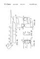
- FIG. 1Ais a sideview of an accessory according to the present invention.
- FIG. 1Bis a sideview of a phone and power source which are suitable for use with the insert of FIG. 1 A.
- FIG. 1Cis a sideview of the insert of FIG. 1A attached to the phone and power source of FIG. 1 B.
- FIG. 1Dis a sideview of the front of a phone including the insert of FIG. 1 A.
- FIG. 2is a sideview of a phone including a centrally positioned virtual image display.
- FIG. 3Ais a sideview of a phone including an insert according to the present invention positioned for use with the right hand.
- FIG. 3Bis a sideview of the phone of FIG. 3A after the user has switched from the right to the left hand and the image on the virtual image display has not been inverted.
- FIG. 3Cillustrates the virtual image display of FIG. 3B after the image on the virtual image display has been inverted.
- FIG. 4Ais a sideview of a side of an insert according to the present invention including a positioning device and a single centrally positioned input device.
- FIG. 4Bis a sideview of a positioning device comprising a plurality of directional inputs.
- FIG. 4Cis a sideview of a side of an insert according to the present invention including a positioning device and a plurality of input devices positioned symmetrically relative to a central longitudinal axis.
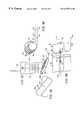
- FIG. 5Aillustrates a virtual image display which can rotate around a lateral axis.
- FIG. 5Bis a cross sectional view of the hinge area of FIG. 5 A.
- FIG. 5Cis a topview of the first and second hub of FIG. 5 B.
- FIG. 5Dis a sideview of the hinge of FIG. 5A disassembled.
- FIG. 6Aillustrates a virtual image display rotated around a longitudinal axis.
- FIG. 6Billustrates the attachment of the virtual image display of FIG. 6 A.
- FIG. 6Cillustrates a virtual image display which can rotate along both a longitudinal and lateral axis.
- FIG. 6Dillustrates a cross section of FIG. 6 B.
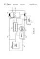
- FIG. 7is a schematic of an insert according to the present invention.
- FIG. 8Aillustrates a side of a phone being rotated through a vertical plane.
- FIG. 8Billustrates an end view of a phone being rotated through a vertical plane.
- FIG. 9is a schematic of the embodiment illustrated in FIG. 2 .
- FIG. 10illustrates a virtual image display which is suitable for use with the present invention.
- FIG. 11illustrates a second virtual image display which is suitable for use with the present invention.
- FIGS. 1A-1Dillustrate a phone accessory 10 in combination with a portable phone according to the present invention.
- the accessoryincludes a virtual image display 12 attached to an insert 14 .
- the insert 14can be positioned between a phone 16 and its power source 18 (shown together in FIG. 1A) such that the phone 16 is in electrical communication with the power source 18 through the insert 14 , as shown in FIG. 1 C.
- the virtual image display 12is in electrical communication with the phone 16 such that the virtual image display 12 can receive image data from the phone 16 .
- the insert 14can also include at least one user input (not illustrated).
- the at least one user inputcan be a positioning device for controlling a position of a cursor on the virtual image display 12 and/or an input device for providing an input at the position of the cursor.
- FIG. 2Another embodiment of the invention is illustrated in FIG. 2 .
- the virtual image display 12is attached to a phone 16 .
- the virtual image display 12is in electrical communication with the phone 16 such that the virtual image display 12 can receive image data from the phone 16 .
- At least one user input(not illustrated) can be positioned on the phone 16 to allow the user to interact with an image on the virtual image display 12 .
- the virtual image display 12can fixed in position relative to the phone or attached to the phone so the face of the virtual image display 12 moves relative to the face of the phone 16 .
- the face of the virtual image display 12can be variably angled relative to the face of the face of the phone.
- the face of the virtual image display 12can be rotated relative to the face of the phone 16 .
- the virtual image display 12can be attached to the phone 16 such that the face of the virtual image display 12 has both rotational and angular movement relative to the phone 16 . As a result, each user can adjust the virtual image display 12 to suit their personal preference.
- the virtual image display 12can be attached so the display 12 centrally positioned relative to the lateral sides of the phone. As a result, the virtual image display 12 is symmetrically positioned relative to the phone 16 and can be viewed regardless of the hand used to hold the phone 16 .
- the embodiments described abovecan include a sensor for detecting the orientation of the phone 16 .
- the sensorcan be used to detect whether a longitudinal axis of the phone is to the left or right of vertical. This can be used to indicate whether the phone is in the user's left or right hand.
- the phone or accessorycan also include logic which is in communication with the sensor and which modifies the orientation of the image in response. Specifically, as the phone 16 is rotated through a vertical plane, the image can be inverted.
- FIGS. 3A-3Cillustrate the results of a user switching hands.
- FIG. 3Aillustrates the orientation of a displayed image 19 when a user holds the phone 16 in the right hand and the phone's longitudinal axis 20 A is to the right of a vertical plane 20 B.
- FIG. 3Aillustrates the orientation of a displayed image 19 when a user holds the phone 16 in the right hand and the phone's longitudinal axis 20 A is to the right of a vertical plane 20 B.
- FIG. 3Billustrates the orientation of the displayed image 19 when the phone's longitudinal axis 20 A is aligned with the vertical plane 20 B.
- FIG. 3Cillustrates the displayed image 19 when the phone is oriented to be held in the user's left hand and thus oriented to the left of the vertical plane 20 B.
- the sensor and logicfunction to orient the displayed image according to how the user is holding the phone and thus allows the user to switch hands freely while viewing the image 19 .
- the logic in combination with the sensorcan function to invert the functions of user input devices in response to the vertical orientation of the phone 16 .
- the logic in combination with the sensorcan function to invert the functions of user input devices in response to the vertical orientation of the phone 16 .
- a virtual image display 12is coupled to an insert 14 which can be positioned between an existing phone 16 and power source 18 .
- An insert first side 21is configured to be attached to a phone attachment side 22 and an insert second side 24 is configured to be attached to a power source attachment side 26 .
- a plurality of electrical contacts 28 on the first sidecontact with electrical contacts on the phone (not shown).
- a plurality of electrical contacts on the second side(not shown) contact with electrical contacts 30 on the power source 18 .
- the phone 16can be in electrical communication with the power source 18 through the insert 14 .
- the insert 14is designed to fit between phone 16 /power source 18 pairs which are configured to be attached to one another without the insert 14 as illustrated in FIG. 1B.
- a cellular phone and the corresponding batteryis an example a suitable phone/power source pair.
- the insert first side 21is preferably shaped substantially similar to the power source attachment side 26 .
- the insert second side 24is preferably shaped substantially similar to the phone attachment side 22 .
- the virtual image display 12is in electrical communication with an insert dataport 32 positioned on the first side of the insert 14 .
- the insert dataport 32is aligned with a phone dataport 34 so the virtual image display 12 can receive image data from the phone 16 through the phone and insert dataports 32 , 34 .
- a central longitudinal axis 36passes through the center of the insert 14 and is aligned with an earpiece 38 and a mouthpiece 40 on the phone 16 as illustrated in FIG. 1 D.
- the virtual image display 12is aligned substantially symmetrical relative to the central longitudinal axis 36 . As a result, the virtual image display is centrally positioned relative to the lateral sides 37 of the phone 16 .
- At least one user input 42can be positioned on the insert 14 .
- the at least one user input 42can be a positioning device 44 for controlling the position of a cursor on the virtual image display 12 .
- Acceptable positioning devices 44include, but are not limited to a track ball or a track pad such as the GlidePoint manufactured by Alps.
- the positioning device 44can also be a plurality of directional indicators as illustrated in FIG. 4 B. By pressing a particular directional button, the user controls which direction the cursor on the virtual image display moves.
- the at least one user input 42can include an input device 46 for providing an input at the position of a cursor on the image display 12 .
- the user input 42can be a user activated button such as a button on a typical computer mouse.
- the user inputcan be positioned on the second side or on an edge of the insert 14 .
- the input device 46can be symmetrically positioned relative to the central longitudinal axis 36 .
- the at least one user input 42can also be a plurality of input devices 46 as illustrated in FIG. 4 C. Each input device 46 can be positioned on the opposite side of the central longitudinal axis 36 from another input device 46 . Each input device 46 can provide the same input, different input or no input.
- each of the at least one inputs 42 illustrated in FIGS. 4A-4Care illustrated on an insert 14 , it is contemplated that the at least one user input 42 for the embodiment of FIG. 2 can be included directly on a phone 16 (not illustrated).
- the virtual image display 12can be attached to the accessory or phone so that the face of the virtual image display can be variably angled relative to the phone face.
- FIGS. 5A-5Dillustrate an embodiment of a mechanism for attaching the display such that the display face 47 A can be variably angled relative to the phone face 47 B.
- the virtual image display 12can be hinged so as to rotate around a lateral axis 48 illustrated in FIG. 5B which is perpendicular to the longitudinal axis 50 .
- a first and second hubs 52are inserted into corresponding first and second openings 54 on a display housing 56 illustrated in FIG. 5 D.
- the display housing 56slides on the hubs 52 during rotation of the virtual image display 12 .
- FIG. 6Aillustrates the virtual image display 12 rotated around the longitudinal axis 50 .
- a mounting support 58 with a central lumen 60extends from a bottom edge 62 of the insert 14 or phone 16 .
- the support 58is placed through a hole 64 in the housing 56 and a locking device 66 is inserted into the support lumen 60 to keep the housing 56 on the support 58 .
- the housing 56is able to turn freely on the mounting support 58 .
- FIG. 6Cillustrates the virtual image display 12 rotated on the lateral 48 and longitudinal 50 axes.
- a bottom edge 62 of the insert 14 or phone 16is rounded as illustrated in FIG. 6 D.
- the mounting support 58 of FIG. 6Bis mounted on a cylinder 64 which is free to rotate within the insert 14 or phone 16 .
- the mounting support 58is placed through the hole 64 in the housing 56 and a locking device 66 is inserted into the lumen 60 of the support 58 to keep the housing 56 on the support 58 .
- the housing 56is able to turn freely on the mounting support 58 and the cylinder 64 is free to turn within the insert 14 or phone 16 allowing the virtual image display 12 to rotate on the lateral 48 and longitudinal 50 axes.
- FIG. 7illustrates a schematic of an insert 14 attached to a phone 16 and a power source 18 .
- the insert 14includes a microprocessor 66 with access to a ROM 68 including programed logic.
- the microprocessoris in electrical communication with the virtual image display 12 and a position sensor 70 for detecting the vertical orientation of the phone 16 .
- the logicinverts an image on the virtual image display 12 in response to the orientation of the phone 16 .
- the logicinverts the image on the virtual image display 12 .
- the logicinverts the image on the virtual image display 12 .
- the microprocessoris in electrical communication with a plurality of user inputs 46 .
- the logiccan affect the function of inputs 46 in response to the vertical orientation of the phone 16 .
- FIG. 4Cillustrates an insert 14 including a first input 46 and a second input 46 A.
- the first input 46can produce first input signal and the second input 46 A can produce a second input signal.
- the logiccan invert the function of the user inputs. For instance as the phone 16 rotates through the vertical plane, the first input 46 performs the function that was performed by the second input before the phone rotated past the vertical plane and visa versa.
- FIG. 9illustrates a schematic for the embodiment of FIG. 2 .
- the position sensing device and the at least one user input 42are positioned within the phone 16 since an insert 14 is not required.
- Suitable virtual image displays 12 for use with the inventionare described in Co-Pending Application Number 08/673,894, entitled “Compact Display System with Two Stage Magnification and Immersed Beam Splitter”, which is incorporated herein by reference.
- An embodiment of a suitable virtual image display 12is illustrated in FIG. 10 .
- the display 12includes an imaging surface 82 on which a source object 84 is formed.
- the illustrated imaging surfaceis a microdisplay which forms the source object.
- the microdisplaymay have a display area of less than 100 mm 2 .
- Light from an illumination source 86is projected onto the imaging surface 82 to cause the source object to be projected into an immersed beam splitting element 88 including a beam splitter 90 immersed in an optically transparent material 92 .
- a portion of the light which reaches the beam splitter 90is reflected by the beam splitter 90 and directed to first optical element 94 .
- the first optical element 94has a reflective function and a magnification function.
- the image formed by the light projected onto the first optical element 94is magnified by the magnification function of the element to form a magnified first virtual image 96 .
- the light from the magnified first virtual image 96is reflected by the reflective function of the element. At least a portion of the light forming the magnified first virtual image 96 passes through the beam splitting element 98 to a second optical element 100 .
- the magnified first virtual image 96 projected onto second optical element 100is magnified by the second optical element 100 as the light traverses the second optical element 100 to form a compound magnified virtual image 98 which is seen by observer 101 .
- the apparent position of the first magnified virtual image 96 relative to the second optical elementis approximately equal to or less than the focal length of the second optical element 100 .
- the compound magnified virtual image 98appears to be positioned further away than the first magnified virtual image 96 , preferably at least 10 inches away. In one embodiment the compound magnified virtual image 98 is at least about 6 feet away to provide for comfortable viewing. order to prevent stray light from interfering with the observer's ability to see the compound virtual image 98 an antireflective coating can be placed on the outside surface 102 of the second optical element 100 .
- FIG. 11illustrates another embodiment of a virtual image display 12 suitable for use with the present invention.
- Total internal reflection off the back surface 106 of the beam splitting element 88is used to further reduce the thickness of the display 12 .
- the display 12 system 10includes an imaging surface 82 on which a source object 84 is formed. Illumination light 104 projects light 104 onto the imaging surface 82 .
- the light 104 projected onto the imaging surface 82causes the source object to be projected toward the back surface 106 of beam splitting element 88 .
- the imaging surface 82By angling the imaging surface 82 such that the light corresponding to the projected source object contacts the back surface 106 of the beam splitting element 88 at an angle ⁇ less than the angle at which total internal reflection occurs, the light forming the projected source object is reflected off the back surface 106 of the beam splitting element 88 to beam splitter 90 .
- the lightis then reflected by the beam splitter 90 and directed to first optical element 94 .
- first optical element 94has a reflective function and a magnification function.
- the image formed by the light projected onto first optical element 94is magnified by the magnification function of the element to form a magnified first virtual image 96 .
- the light from the magnified first virtual image 96is reflected by the reflective function of the element. At least a portion of the light forming the magnified first virtual image 96 passes through the beam splitting element 88 to a second optical element 100 .
- the magnified first virtual image 96 formed by the light projected onto second optical element 100is magnified by the second optical element 100 as the light traverses the second optical element 100 and is seen as a compound magnified virtual image 98 by the observer 108 .
- the angle ⁇ between the beam splitter 90 and plane 110limits how close the first and second optical elements 94 , 100 may be positioned relative to each other (shown in FIGS. 11 and 12 as distance t) and hence limits the overall thickness T of the display system.
- the magnification performed by the beamsplitting element 88enables a smaller beamsplitting element 88 to be used in the display system, which, in turn, enables the beamsplitting element 88 to be positioned at a tighter angle ⁇ .
- the angle ⁇ at which the beamsplitting element 88 is positionedthe distance t between the first and second optical elements 94 , 100 is reduced.
- an immersed beam splitteralso enables a smaller imaging surface 82 to be used and/or for the imaging surface 82 to be positioned further away from the beam splitter 90 than if the source object were projected from the imaging surface 82 to the beam splitter 90 through air. This is important to the compact design of the display system of the present invention since it enables the imaging surface to be positioned out from between optical elements 94 , 100 and thus out of the field of view provided by the optical system.
Landscapes
- Engineering & Computer Science (AREA)
- Signal Processing (AREA)
- Telephone Set Structure (AREA)
Abstract
Description
Claims (32)
Priority Applications (3)
| Application Number | Priority Date | Filing Date | Title |
|---|---|---|---|
| US09/031,263US6275714B1 (en) | 1998-02-26 | 1998-02-26 | Phone with ergonomic virtual image display |
| PCT/US1999/002819WO1999044347A1 (en) | 1998-02-26 | 1999-02-10 | Phone with ergonomic virtual image display |
| AU32885/99AAU3288599A (en) | 1998-02-26 | 1999-02-10 | Phone with ergonomic virtual image display |
Applications Claiming Priority (1)
| Application Number | Priority Date | Filing Date | Title |
|---|---|---|---|
| US09/031,263US6275714B1 (en) | 1998-02-26 | 1998-02-26 | Phone with ergonomic virtual image display |
Publications (1)
| Publication Number | Publication Date |
|---|---|
| US6275714B1true US6275714B1 (en) | 2001-08-14 |
Family
ID=21858496
Family Applications (1)
| Application Number | Title | Priority Date | Filing Date |
|---|---|---|---|
| US09/031,263Expired - LifetimeUS6275714B1 (en) | 1998-02-26 | 1998-02-26 | Phone with ergonomic virtual image display |
Country Status (3)
| Country | Link |
|---|---|
| US (1) | US6275714B1 (en) |
| AU (1) | AU3288599A (en) |
| WO (1) | WO1999044347A1 (en) |
Cited By (24)
| Publication number | Priority date | Publication date | Assignee | Title |
|---|---|---|---|---|
| US20010054988A1 (en)* | 2000-05-12 | 2001-12-27 | Cone George W. | Portable communication device with virtual image display module |
| US20020028698A1 (en)* | 2000-09-06 | 2002-03-07 | Telefonaktiebolaget L M Ericsson (Publ) | Display apparatus |
| US20020151283A1 (en)* | 2001-04-02 | 2002-10-17 | Pallakoff Matthew G. | Coordinating images displayed on devices with two or more displays |
| US20030001817A1 (en)* | 2001-06-21 | 2003-01-02 | Lg Electronics Inc. | Folder type mobile telephone and operating method thereof |
| US20030050019A1 (en)* | 2001-09-07 | 2003-03-13 | Dowling Eric Morgan | Mobile units with fexible-retractable peripherals |
| US20030060239A1 (en)* | 2001-09-25 | 2003-03-27 | Koninklijke Philips Electronics N.V. | Method and apparatus to aid in viewing a portable device |
| US20030090438A1 (en)* | 2001-01-30 | 2003-05-15 | Noriyoshi Sato | Foldable portable information terminal device and method for information display of the device |
| US6687515B1 (en)* | 1998-10-07 | 2004-02-03 | Denso Corporation | Wireless video telephone with ambient light sensor |
| US20040029409A1 (en)* | 2002-08-12 | 2004-02-12 | Sony Corporation | Interface for personal digital assistant accessory |
| US20040090552A1 (en)* | 2002-06-26 | 2004-05-13 | Takaaki Watanabe | Folding-type portable information device provided with image capturing function |
| US6791773B2 (en)* | 2000-05-23 | 2004-09-14 | Olympus Corporation | Portable image display |
| US6792293B1 (en)* | 2000-09-13 | 2004-09-14 | Motorola, Inc. | Apparatus and method for orienting an image on a display of a wireless communication device |
| US6803884B1 (en)* | 1999-03-11 | 2004-10-12 | Minolta Co., Ltd. | Projection image display device |
| US20040229664A1 (en)* | 2003-05-12 | 2004-11-18 | Siemens Information And Communication Mobile Llc. | Mobile communication device having extendable display |
| US20040229662A1 (en)* | 2003-05-12 | 2004-11-18 | Siemens Information | Mobile communication device having extendable display |
| US6871083B2 (en)* | 2000-01-31 | 2005-03-22 | Nec Corporation | Portable radio device |
| US20050148375A1 (en)* | 2003-12-31 | 2005-07-07 | Sony Ericsson Mobile Communications Ab | Apparatus for mobile terminal display |
| US20050176471A1 (en)* | 2004-02-05 | 2005-08-11 | Hitachi, Ltd. | Mobile terminal device |
| US20050239448A1 (en)* | 2004-04-12 | 2005-10-27 | Bayne Anthony J | System and method for the distribution of advertising and associated coupons via mobile media platforms |
| US20050250532A1 (en)* | 2004-05-06 | 2005-11-10 | Samsung Electronics Co., Ltd. | Sliding/swing-type portable apparatus having self-retaining function |
| US20090195708A1 (en)* | 2006-09-29 | 2009-08-06 | Brother Kogyo Kabushiki Kaisha | Image Projection Device, Image Projection Method, Computer Readable Recording Medium Recording Program Used in Image Projection Device |
| US20100297930A1 (en)* | 2009-05-20 | 2010-11-25 | Harris Technology, Llc | Portable Device with a Vehicle driver Detection |
| US20110065429A1 (en)* | 2009-09-11 | 2011-03-17 | Samsung Electronics Co., Ltd. | Apparatus for enhancing efficiency of antenna in a mobile terminal |
| US10251030B2 (en) | 2017-02-16 | 2019-04-02 | Datron World Communications, Inc. | Portable radio system for dual programmable push-to-talk buttons and method for the same |
Families Citing this family (1)
| Publication number | Priority date | Publication date | Assignee | Title |
|---|---|---|---|---|
| US6805490B2 (en) | 2002-09-30 | 2004-10-19 | Nokia Corporation | Method and system for beam expansion in a display device |
Citations (13)
| Publication number | Priority date | Publication date | Assignee | Title |
|---|---|---|---|---|
| US5485504A (en)* | 1991-08-07 | 1996-01-16 | Alcatel N.V. | Hand-held radiotelephone with video transmission and display |
| US5490202A (en)* | 1993-01-29 | 1996-02-06 | Mitsubishi Denki Kabushiki Kaisha | Attachable and detachable additional device for use with a portable telephone for electrically connecting with the portable telephone external equipment |
| US5491491A (en)* | 1994-10-31 | 1996-02-13 | Motorola | Portable electronic equipment with binocular virtual display |
| US5513383A (en)* | 1993-09-14 | 1996-04-30 | Space Systems/Loral, Inc. | Mobile communication terminal having extendable antenna |
| US5542106A (en)* | 1994-09-15 | 1996-07-30 | Motorola, Inc. | Electronic device having an RF circuit integrated into a movable housing element |
| WO1996035288A1 (en)* | 1995-05-03 | 1996-11-07 | Siemens Aktiengesellschaft | Portable radio communication device with inbtegrated camera and image display device |
| JPH09198352A (en)* | 1996-01-18 | 1997-07-31 | Mitsubishi Electric Corp | Portable information communication device |
| WO1997029582A1 (en) | 1996-02-12 | 1997-08-14 | Sprint Telecommunications Venture | Mobile telephone having user interface including navigation and selection controls |
| JPH09219755A (en) | 1995-09-21 | 1997-08-19 | Internatl Business Mach Corp <Ibm> | Personal communicator |
| US5771124A (en)* | 1996-07-02 | 1998-06-23 | Siliscape | Compact display system with two stage magnification and immersed beam splitter |
| US5867795A (en)* | 1996-08-23 | 1999-02-02 | Motorola, Inc. | Portable electronic device with transceiver and visual image display |
| US5901222A (en)* | 1996-10-31 | 1999-05-04 | Lucent Technologies Inc. | User interface for portable telecommunication devices |
| US5969698A (en)* | 1993-11-29 | 1999-10-19 | Motorola, Inc. | Manually controllable cursor and control panel in a virtual image |
- 1998
- 1998-02-26USUS09/031,263patent/US6275714B1/ennot_activeExpired - Lifetime
- 1999
- 1999-02-10WOPCT/US1999/002819patent/WO1999044347A1/enactiveApplication Filing
- 1999-02-10AUAU32885/99Apatent/AU3288599A/ennot_activeAbandoned
Patent Citations (16)
| Publication number | Priority date | Publication date | Assignee | Title |
|---|---|---|---|---|
| US5485504A (en)* | 1991-08-07 | 1996-01-16 | Alcatel N.V. | Hand-held radiotelephone with video transmission and display |
| US5490202A (en)* | 1993-01-29 | 1996-02-06 | Mitsubishi Denki Kabushiki Kaisha | Attachable and detachable additional device for use with a portable telephone for electrically connecting with the portable telephone external equipment |
| US5513383A (en)* | 1993-09-14 | 1996-04-30 | Space Systems/Loral, Inc. | Mobile communication terminal having extendable antenna |
| US5969698A (en)* | 1993-11-29 | 1999-10-19 | Motorola, Inc. | Manually controllable cursor and control panel in a virtual image |
| US5542106A (en)* | 1994-09-15 | 1996-07-30 | Motorola, Inc. | Electronic device having an RF circuit integrated into a movable housing element |
| US5491491A (en)* | 1994-10-31 | 1996-02-13 | Motorola | Portable electronic equipment with binocular virtual display |
| WO1996035288A1 (en)* | 1995-05-03 | 1996-11-07 | Siemens Aktiengesellschaft | Portable radio communication device with inbtegrated camera and image display device |
| US6085112A (en)* | 1995-05-03 | 2000-07-04 | Siemens Aktiengesellschaft | Communication device |
| JPH09219755A (en) | 1995-09-21 | 1997-08-19 | Internatl Business Mach Corp <Ibm> | Personal communicator |
| EP0833486A2 (en) | 1995-09-21 | 1998-04-01 | International Business Machines Corporation | Personal communicator integrated in a portable telephone |
| US5970418A (en)* | 1995-09-21 | 1999-10-19 | International Business Machines Corporation | Personal communicator including a handset phone with an integrated virtual image display |
| JPH09198352A (en)* | 1996-01-18 | 1997-07-31 | Mitsubishi Electric Corp | Portable information communication device |
| WO1997029582A1 (en) | 1996-02-12 | 1997-08-14 | Sprint Telecommunications Venture | Mobile telephone having user interface including navigation and selection controls |
| US5771124A (en)* | 1996-07-02 | 1998-06-23 | Siliscape | Compact display system with two stage magnification and immersed beam splitter |
| US5867795A (en)* | 1996-08-23 | 1999-02-02 | Motorola, Inc. | Portable electronic device with transceiver and visual image display |
| US5901222A (en)* | 1996-10-31 | 1999-05-04 | Lucent Technologies Inc. | User interface for portable telecommunication devices |
Non-Patent Citations (1)
| Title |
|---|
| Patent Abstract Of Japan, vol. 097, No. 011, Nov. 28, 1997; JP 09 198352. |
Cited By (46)
| Publication number | Priority date | Publication date | Assignee | Title |
|---|---|---|---|---|
| US6687515B1 (en)* | 1998-10-07 | 2004-02-03 | Denso Corporation | Wireless video telephone with ambient light sensor |
| US6803884B1 (en)* | 1999-03-11 | 2004-10-12 | Minolta Co., Ltd. | Projection image display device |
| US6871083B2 (en)* | 2000-01-31 | 2005-03-22 | Nec Corporation | Portable radio device |
| US7068258B2 (en)* | 2000-05-12 | 2006-06-27 | Emagin Corporation | Portable communication device with virtual image display module |
| US20010054988A1 (en)* | 2000-05-12 | 2001-12-27 | Cone George W. | Portable communication device with virtual image display module |
| US20050013006A1 (en)* | 2000-05-23 | 2005-01-20 | Olympus Corporation | Portable image display |
| US6791773B2 (en)* | 2000-05-23 | 2004-09-14 | Olympus Corporation | Portable image display |
| US7009787B2 (en) | 2000-05-23 | 2006-03-07 | Olympus Corporation | Portable image display |
| US20020028698A1 (en)* | 2000-09-06 | 2002-03-07 | Telefonaktiebolaget L M Ericsson (Publ) | Display apparatus |
| US6792293B1 (en)* | 2000-09-13 | 2004-09-14 | Motorola, Inc. | Apparatus and method for orienting an image on a display of a wireless communication device |
| US20030090438A1 (en)* | 2001-01-30 | 2003-05-15 | Noriyoshi Sato | Foldable portable information terminal device and method for information display of the device |
| US7016704B2 (en)* | 2001-04-02 | 2006-03-21 | Move Mobile Systems, Inc. | Coordinating images displayed on devices with two or more displays |
| WO2002079913A3 (en)* | 2001-04-02 | 2003-04-17 | Matthew G Pallakoff | Coordinating images displayed on devices with two or more displays |
| US20020151283A1 (en)* | 2001-04-02 | 2002-10-17 | Pallakoff Matthew G. | Coordinating images displayed on devices with two or more displays |
| US20080139252A1 (en)* | 2001-06-21 | 2008-06-12 | Lg Electronics Inc. | Folder type mobile telephone and operating method thereof |
| US7400902B2 (en)* | 2001-06-21 | 2008-07-15 | Lg Electronics Inc. | Folder type mobile telephone and operating method thereof |
| US20030001817A1 (en)* | 2001-06-21 | 2003-01-02 | Lg Electronics Inc. | Folder type mobile telephone and operating method thereof |
| US20050136999A1 (en)* | 2001-06-21 | 2005-06-23 | Lg Electronics Inc. | Folder type mobile telephone and operating method thereof |
| US7583988B2 (en) | 2001-06-21 | 2009-09-01 | Lg Electronics Inc. | Folder type mobile telephone and operating method thereof |
| US8903462B2 (en) | 2001-06-21 | 2014-12-02 | Lg Electronics Inc. | Folder type mobile telephone and operating method thereof |
| US8483766B2 (en) | 2001-06-21 | 2013-07-09 | Lg Electronics Inc. | Folder type mobile telephone and operating method thereof |
| US20030050019A1 (en)* | 2001-09-07 | 2003-03-13 | Dowling Eric Morgan | Mobile units with fexible-retractable peripherals |
| US20030060239A1 (en)* | 2001-09-25 | 2003-03-27 | Koninklijke Philips Electronics N.V. | Method and apparatus to aid in viewing a portable device |
| US20040090552A1 (en)* | 2002-06-26 | 2004-05-13 | Takaaki Watanabe | Folding-type portable information device provided with image capturing function |
| US7373186B2 (en)* | 2002-06-26 | 2008-05-13 | Kyocera Corporation | Folding-type portable information device provided with image capturing function |
| US20040029409A1 (en)* | 2002-08-12 | 2004-02-12 | Sony Corporation | Interface for personal digital assistant accessory |
| US20040229662A1 (en)* | 2003-05-12 | 2004-11-18 | Siemens Information | Mobile communication device having extendable display |
| US7149557B2 (en) | 2003-05-12 | 2006-12-12 | Siemens Communications, Inc. | Mobile communication device having extendable display |
| US20040229664A1 (en)* | 2003-05-12 | 2004-11-18 | Siemens Information And Communication Mobile Llc. | Mobile communication device having extendable display |
| US20050148375A1 (en)* | 2003-12-31 | 2005-07-07 | Sony Ericsson Mobile Communications Ab | Apparatus for mobile terminal display |
| US20050176471A1 (en)* | 2004-02-05 | 2005-08-11 | Hitachi, Ltd. | Mobile terminal device |
| US7386332B2 (en)* | 2004-02-05 | 2008-06-10 | Hitachi, Ltd. | Mobile terminal device |
| US20050239495A1 (en)* | 2004-04-12 | 2005-10-27 | Bayne Anthony J | System and method for the distribution of advertising and associated coupons via mobile media platforms |
| US7844288B2 (en) | 2004-04-12 | 2010-11-30 | Anthony J Bayne | System and method for the distribution of advertising and associated coupons via mobile media platforms |
| US20090088219A1 (en)* | 2004-04-12 | 2009-04-02 | Bayne Anthony J | System and method for the distribution of advertising and associated coupons via mobile media platforms |
| US20050239448A1 (en)* | 2004-04-12 | 2005-10-27 | Bayne Anthony J | System and method for the distribution of advertising and associated coupons via mobile media platforms |
| US7463898B2 (en) | 2004-04-12 | 2008-12-09 | Bayne Anthony J | System and method for the distribution of advertising and associated coupons via mobile media platforms |
| US7369882B2 (en)* | 2004-05-06 | 2008-05-06 | Samsung Electronics Co., Ltd | Sliding/swing-type portable apparatus having self-retaining function |
| US20050250532A1 (en)* | 2004-05-06 | 2005-11-10 | Samsung Electronics Co., Ltd. | Sliding/swing-type portable apparatus having self-retaining function |
| US7899876B2 (en)* | 2006-09-29 | 2011-03-01 | Brother Kogyo Kabushiki Kaisha | Image projection device, image projection method, computer readable recording medium recording program used in image projection device |
| US20090195708A1 (en)* | 2006-09-29 | 2009-08-06 | Brother Kogyo Kabushiki Kaisha | Image Projection Device, Image Projection Method, Computer Readable Recording Medium Recording Program Used in Image Projection Device |
| US20100297930A1 (en)* | 2009-05-20 | 2010-11-25 | Harris Technology, Llc | Portable Device with a Vehicle driver Detection |
| US20110065429A1 (en)* | 2009-09-11 | 2011-03-17 | Samsung Electronics Co., Ltd. | Apparatus for enhancing efficiency of antenna in a mobile terminal |
| US9209849B2 (en)* | 2009-09-11 | 2015-12-08 | Samsung Electronics Co., Ltd. | Apparatus for enhancing efficiency of antenna in a mobile terminal |
| US10251030B2 (en) | 2017-02-16 | 2019-04-02 | Datron World Communications, Inc. | Portable radio system for dual programmable push-to-talk buttons and method for the same |
| US11064316B2 (en) | 2017-02-16 | 2021-07-13 | Datron World Communications, Inc. | Portable radio system for dual programmable push-to-talk buttons and method for the same |
Also Published As
| Publication number | Publication date |
|---|---|
| WO1999044347A1 (en) | 1999-09-02 |
| AU3288599A (en) | 1999-09-15 |
Similar Documents
| Publication | Publication Date | Title |
|---|---|---|
| US6275714B1 (en) | Phone with ergonomic virtual image display | |
| KR100237990B1 (en) | Personal communication device | |
| EP1324100B1 (en) | Portable terminal device having a display unit utilizing a holographic screen | |
| EP1176449B1 (en) | Compact optical system and packaging for head mounted display | |
| US4568080A (en) | Display apparatus | |
| EP1387572B1 (en) | Portable electronic device | |
| US20040130644A1 (en) | Folded compact image capture apparatus | |
| US7432977B2 (en) | Portable electronic device with built-in digital camera | |
| JP2002199060A (en) | Digital projection system for telephone and portable information terminal device | |
| JP2003333151A (en) | Personal communicator | |
| JP2003522974A (en) | Binocular display device | |
| EP4239986A1 (en) | Electronic device comprising hinge module | |
| US11435781B1 (en) | Computing device | |
| US12066742B2 (en) | Blocking mechanism of privacy protection shutter for camera of electronic device | |
| JP2005062314A (en) | Retroreflective optical screen and observation device using the same | |
| US20240195902A1 (en) | Electronic Device | |
| US8359075B2 (en) | Apparatus with transparent display | |
| JPH07505723A (en) | Improvements in viewer assemblies and observable materials used therein | |
| US7191492B2 (en) | Swivel structure having direction indication | |
| JP2002189532A (en) | Hand-held computer | |
| US12339449B2 (en) | Head mounted device | |
| JP3074808U (en) | Enlarged display device for mobile phone and mobile phone using the same | |
| KR102401854B1 (en) | Augmented reality glass for multi-function | |
| JP2005333219A (en) | Portable information display device | |
| JP4121908B2 (en) | Mobile terminal device |
Legal Events
| Date | Code | Title | Description |
|---|---|---|---|
| AS | Assignment | Owner name:SILISCAPE, INC., CALIFORNIA Free format text:ASSIGNMENT OF ASSIGNORS INTEREST;ASSIGNORS:PHILLIPS, DAVID L.;KINTZ, GREGORY J.;REEL/FRAME:009598/0648;SIGNING DATES FROM 19981110 TO 19981111 | |
| AS | Assignment | Owner name:INVISIO, INC., CALIFORNIA Free format text:CHANGE OF NAME;ASSIGNOR:SILISCAPE, INC.;REEL/FRAME:010670/0008 Effective date:19990329 | |
| AS | Assignment | Owner name:INVISO, INC., CALIFORNIA Free format text:CHANGE OF NAME;ASSIGNOR:SILISCAPE, INC.;REEL/FRAME:010918/0642 Effective date:19990329 | |
| STCF | Information on status: patent grant | Free format text:PATENTED CASE | |
| AS | Assignment | Owner name:ARCH VENTURE FUND II, L.P., ILLINOIS Free format text:SECURITY INTEREST;ASSIGNOR:INVISO, INC.;REEL/FRAME:012691/0488 Effective date:20010427 Owner name:AVI PARTNERS GROWTH FUND, II, L.P., CALIFORNIA Free format text:SECURITY INTEREST;ASSIGNOR:INVISO, INC.;REEL/FRAME:012691/0488 Effective date:20010427 Owner name:CHEVRON TECHNOLOGY VENTURES LLC, CALIFORNIA Free format text:SECURITY INTEREST;ASSIGNOR:INVISO, INC.;REEL/FRAME:012691/0488 Effective date:20010427 Owner name:RIDGEWOOD CAPITAL CORP., CALIFORNIA Free format text:SECURITY INTEREST;ASSIGNOR:INVISO, INC.;REEL/FRAME:012691/0488 Effective date:20010427 Owner name:SUTHERLAND, IVAN, CALIFORNIA Free format text:SECURITY INTEREST;ASSIGNOR:INVISO, INC.;REEL/FRAME:012691/0488 Effective date:20010427 Owner name:ASSOCIATE VENTURE INVESTORS III, L.P., CALIFORNIA Free format text:SECURITY INTEREST;ASSIGNOR:INVISO, INC.;REEL/FRAME:012691/0488 Effective date:20010427 Owner name:AVI SILICON VALLEY PARTNERS, L.P., CALIFORNIA Free format text:SECURITY INTEREST;ASSIGNOR:INVISO, INC.;REEL/FRAME:012691/0488 Effective date:20010427 Owner name:CYPRESS VENTURE FUND L.L.C., CALIFORNIA Free format text:SECURITY INTEREST;ASSIGNOR:INVISO, INC.;REEL/FRAME:012691/0488 Effective date:20010427 Owner name:THOMAS A. KELLEY & ASSOCIATES PROFIT-SHARING PLAN, Free format text:SECURITY INTEREST;ASSIGNOR:INVISO, INC.;REEL/FRAME:012691/0488 Effective date:20010427 Owner name:AVI CAPITAL, L.P., CALIFORNIA Free format text:SECURITY INTEREST;ASSIGNOR:INVISO, INC.;REEL/FRAME:012691/0488 Effective date:20010427 Owner name:BIALEK, FRED, CALIFORNIA Free format text:SECURITY INTEREST;ASSIGNOR:INVISO, INC.;REEL/FRAME:012691/0488 Effective date:20010427 Owner name:MGN OPPORTUNITY GROUP LLC, WASHINGTON Free format text:SECURITY INTEREST;ASSIGNOR:INVISO, INC.;REEL/FRAME:012691/0488 Effective date:20010427 Owner name:RUSSELL-SHAPIRO, WILLIAM AND ALICE RUSSEL-SHAPIRO, Free format text:SECURITY INTEREST;ASSIGNOR:INVISO, INC.;REEL/FRAME:012691/0488 Effective date:20010427 | |
| AS | Assignment | Owner name:BRILLIAN CORPORATION, ARIZONA Free format text:ASSIGNMENT OF ASSIGNORS INTEREST;ASSIGNOR:INVISO, INC.;REEL/FRAME:015661/0265 Effective date:20040223 | |
| FPAY | Fee payment | Year of fee payment:4 | |
| AS | Assignment | Owner name:THREE-FIVE SYSTEMS, INC., ARIZONA Free format text:RELEASE OF SECURITY INTEREST;ASSIGNORS:ARCH VENTURE FUND II, L.P.;AVI PARTNERS GROWTH FUND, II, L.P.;CHEVRON TECHNOLOGY VENTURES LLC;AND OTHERS;REEL/FRAME:015756/0362 Effective date:20020425 | |
| AS | Assignment | Owner name:REGENMACHER LTD., FLORIDA Free format text:SECURITIES PURCHASE AGREEMENT;ASSIGNOR:BRILLIAN CORPORATION;REEL/FRAME:016470/0120 Effective date:20050418 | |
| AS | Assignment | Owner name:SILVER POINT FINANCE, LLC, AS COLLATERAL AGENT, CO Free format text:GRANT OF SECURITY INTEREST;ASSIGNOR:VIVITAR CORPORATION;REEL/FRAME:020072/0247 Effective date:20071026 Owner name:SILVER POINT FINANCE, LLC, AS COLLATERAL AGENT, CO Free format text:GRANT OF SECURITY INTEREST;ASSIGNOR:SYNTAX-BRILLIAN CORPORATION;REEL/FRAME:020072/0232 Effective date:20071026 | |
| AS | Assignment | Owner name:BRILLIAN CORPORATION (N/K/A SYNTAX-BRILLIAN CORP.) Free format text:RELEASE OF SECURITY INTEREST;ASSIGNOR:REGENMACHER LTD.;REEL/FRAME:020261/0572 Effective date:20071210 | |
| AS | Assignment | Owner name:COMPOUND PHOTONICS U.S. CORPORATION, ARIZONA Free format text:ASSIGNMENT OF ASSIGNORS INTEREST;ASSIGNOR:SYNTAX-BRILLIAN CORPORATION;REEL/FRAME:020609/0406 Effective date:20071221 | |
| FEPP | Fee payment procedure | Free format text:PAYER NUMBER DE-ASSIGNED (ORIGINAL EVENT CODE: RMPN); ENTITY STATUS OF PATENT OWNER: SMALL ENTITY Free format text:PAYOR NUMBER ASSIGNED (ORIGINAL EVENT CODE: ASPN); ENTITY STATUS OF PATENT OWNER: SMALL ENTITY | |
| FPAY | Fee payment | Year of fee payment:8 | |
| AS | Assignment | Owner name:COMPOUND PHOTONICS U.S. CORPORATION, ARIZONA Free format text:RELEASE BY SECURED PARTY;ASSIGNOR:SILVER POINT FINANCE, LLC;REEL/FRAME:023056/0972 Effective date:20090731 | |
| AS | Assignment | Owner name:COMPOUND PHOTONICS LIMITED, ARIZONA Free format text:ASSIGNMENT OF ASSIGNORS INTEREST;ASSIGNOR:COMPOUND PHOTONICS U.S. CORPORATION;REEL/FRAME:024640/0332 Effective date:20100121 | |
| AS | Assignment | Owner name:VOLLIN HOLDINGS LIMITED, CYPRUS Free format text:SECURITY AGREEMENT;ASSIGNORS:COMPOUND PHOTONICS LIMITED;COMPOUND PHOTONICS U.S. CORPORATION;FURY TECHNOLOGIES CORPORATION;REEL/FRAME:024944/0283 Effective date:20100825 | |
| AS | Assignment | Owner name:COMPOUND PHOTONICS U.S. CORPORATION, ARIZONA Free format text:ASSIGNMENT OF ASSIGNORS INTEREST;ASSIGNOR:SB LIQUIDATION TRUST AND THE LENDER TRUST;REEL/FRAME:027399/0506 Effective date:20110922 | |
| AS | Assignment | Owner name:COMPOUND PHOTONICS LIMITED, UNITED KINGDOM Free format text:ASSIGNMENT OF ASSIGNORS INTEREST;ASSIGNOR:COMPOUND PHOTONICS U.S. CORPORATION;REEL/FRAME:027405/0966 Effective date:20111206 | |
| FPAY | Fee payment | Year of fee payment:12 | |
| AS | Assignment | Owner name:SYNTAX-BRILLIAN CORPORATION, DELAWARE Free format text:CHANGE OF NAME;ASSIGNOR:BRILLIAN CORPORATION;REEL/FRAME:036777/0357 Effective date:20051130 |