US6275628B1 - Single-ended long period grating optical device - Google Patents
Single-ended long period grating optical deviceDownload PDFInfo
- Publication number
- US6275628B1 US6275628B1US09/440,499US44049999AUS6275628B1US 6275628 B1US6275628 B1US 6275628B1US 44049999 AUS44049999 AUS 44049999AUS 6275628 B1US6275628 B1US 6275628B1
- Authority
- US
- United States
- Prior art keywords
- optical waveguide
- long period
- period grating
- cladding
- optical device
- Prior art date
- Legal status (The legal status is an assumption and is not a legal conclusion. Google has not performed a legal analysis and makes no representation as to the accuracy of the status listed.)
- Expired - Fee Related
Links
- 230000003287optical effectEffects0.000titleclaimsabstractdescription151
- 238000005253claddingMethods0.000claimsabstractdescription73
- 238000000034methodMethods0.000claimsdescription42
- 230000008569processEffects0.000claimsdescription36
- 238000000576coating methodMethods0.000claimsdescription18
- 238000002839fiber optic waveguideMethods0.000claimsdescription17
- 239000011248coating agentSubstances0.000claimsdescription15
- 230000000737periodic effectEffects0.000claimsdescription13
- 230000008878couplingEffects0.000claimsdescription10
- 238000010168coupling processMethods0.000claimsdescription10
- 238000005859coupling reactionMethods0.000claimsdescription10
- 230000007613environmental effectEffects0.000claimsdescription9
- 239000000463materialSubstances0.000claimsdescription9
- 230000003595spectral effectEffects0.000claimsdescription9
- 238000004519manufacturing processMethods0.000claimsdescription4
- 230000008859changeEffects0.000claimsdescription2
- 238000005530etchingMethods0.000claimsdescription2
- 238000000151depositionMethods0.000claims4
- 239000000835fiberSubstances0.000description22
- 238000002955isolationMethods0.000description6
- 230000008901benefitEffects0.000description5
- 239000004593EpoxySubstances0.000description4
- PCHJSUWPFVWCPO-UHFFFAOYSA-NgoldChemical compound[Au]PCHJSUWPFVWCPO-UHFFFAOYSA-N0.000description4
- 239000010931goldSubstances0.000description4
- 229910052737goldInorganic materials0.000description4
- 230000004048modificationEffects0.000description4
- 238000012986modificationMethods0.000description4
- 239000013307optical fiberSubstances0.000description4
- 230000001902propagating effectEffects0.000description4
- NIXOWILDQLNWCW-UHFFFAOYSA-MAcrylateChemical compound[O-]C(=O)C=CNIXOWILDQLNWCW-UHFFFAOYSA-M0.000description3
- YMWUJEATGCHHMB-UHFFFAOYSA-NDichloromethaneChemical compoundClCClYMWUJEATGCHHMB-UHFFFAOYSA-N0.000description3
- 230000005540biological transmissionEffects0.000description3
- 125000003700epoxy groupChemical group0.000description2
- 239000002184metalSubstances0.000description2
- 229910052751metalInorganic materials0.000description2
- 229920000647polyepoxidePolymers0.000description2
- 238000001228spectrumMethods0.000description2
- 230000002238attenuated effectEffects0.000description1
- 238000004891communicationMethods0.000description1
- 230000007797corrosionEffects0.000description1
- 238000005260corrosionMethods0.000description1
- 230000007547defectEffects0.000description1
- 230000001419dependent effectEffects0.000description1
- 238000013461designMethods0.000description1
- 238000001704evaporationMethods0.000description1
- 230000008020evaporationEffects0.000description1
- 238000001914filtrationMethods0.000description1
- 230000003993interactionEffects0.000description1
- 230000009149molecular bindingEffects0.000description1
- 238000004806packaging method and processMethods0.000description1
- 230000000644propagated effectEffects0.000description1
- 238000002310reflectometryMethods0.000description1
- 238000010561standard procedureMethods0.000description1
- 239000000126substanceSubstances0.000description1
- 238000000411transmission spectrumMethods0.000description1
Images


Classifications
- G—PHYSICS
- G02—OPTICS
- G02B—OPTICAL ELEMENTS, SYSTEMS OR APPARATUS
- G02B6/00—Light guides; Structural details of arrangements comprising light guides and other optical elements, e.g. couplings
- G02B6/02—Optical fibres with cladding with or without a coating
- G02B6/02057—Optical fibres with cladding with or without a coating comprising gratings
- G—PHYSICS
- G02—OPTICS
- G02B—OPTICAL ELEMENTS, SYSTEMS OR APPARATUS
- G02B6/00—Light guides; Structural details of arrangements comprising light guides and other optical elements, e.g. couplings
- G02B6/10—Light guides; Structural details of arrangements comprising light guides and other optical elements, e.g. couplings of the optical waveguide type
- G02B6/14—Mode converters
- G—PHYSICS
- G02—OPTICS
- G02B—OPTICAL ELEMENTS, SYSTEMS OR APPARATUS
- G02B6/00—Light guides; Structural details of arrangements comprising light guides and other optical elements, e.g. couplings
- G02B6/24—Coupling light guides
- G02B6/26—Optical coupling means
- G02B6/28—Optical coupling means having data bus means, i.e. plural waveguides interconnected and providing an inherently bidirectional system by mixing and splitting signals
- G02B6/293—Optical coupling means having data bus means, i.e. plural waveguides interconnected and providing an inherently bidirectional system by mixing and splitting signals with wavelength selective means
- G02B6/29304—Optical coupling means having data bus means, i.e. plural waveguides interconnected and providing an inherently bidirectional system by mixing and splitting signals with wavelength selective means operating by diffraction, e.g. grating
- G02B6/29316—Light guides comprising a diffractive element, e.g. grating in or on the light guide such that diffracted light is confined in the light guide
- G02B6/29317—Light guides of the optical fibre type
Definitions
- the present inventionrelates to optical devices.
- itrelates to long period grating optical devices which are capable of undergoing single-ended operation.
- Optical fiber gratingsare well established components that have been used in industry for communication and sensing applications. These devices are formed by exposing a germanosilicate fiber to spatially periodic intensity from a high-power ultraviolet (UV) source. Interaction with the UV light affects molecular binding within the optical fiber core and creates refractive index perturbations. The perturbations form a grating structure. Based on periodicity, the grating will selectively reflect or couple light at a specific band of wavelengths to guided or nonguided modes of the waveguide.
- UVultraviolet
- Long period gratingstypically have a plurality of index perturbations of width w spaced apart by a periodic distance ⁇ , where typically 50 ⁇ m ⁇ 1500 ⁇ m.
- the perturbationsare formed within the core of the waveguide and form an angle with the longitudinal axis of the waveguide.
- the waveguideis designed to transmit broadband light at a wavelength centered about ⁇ .
- the spacing of the perturbationsis chosen to couple transmitted light in the region of at least one wavelength from the guided mode into lossy non-guided modes in the cladding thereby reducing in intensity the band of light centered about a plurality of coupling wavelengths.
- Vengsarkar et al.(U.S. Pat. No. 5,641,956) describe an optical waveguide sensor arrangement which comprises an optical waveguide having guided modes, lossy non-guided modes, and a long period grating coupling the guided modes to the lossy non-guided modes.
- the light contained in the non-guided modesinteract with surface defects on the optical waveguide and is rapidly attenuated. These modes are referred to as lossy.
- the long period gratingcan be used as a sensor because it converts light traveling in the guided modes of the optical waveguide to the lossy non-guided modes of the optical waveguide at one or more wavelengths as determined by various environmental parameters being measured. This produces a wavelength transmission spectrum functionally dependent on the parameter sensed.
- Long period gratingsare typically used to couple light from the core mode to the forward propagating cladding mode to result in a transmitted signal.
- external methodsmust be implemented to return the signal through the input fiber.
- One way this is achievedis by placing a reflector or filter over the entire fiber endface after the long period grating. In so doing, a reflective metal such as gold or a dielectric is deposited onto the fiber endface surface. Since the reflector covers the entire fiber endface, the cladding modes coupled by the long period grating are reflected as well as the fundamental mode.
- Placement of the mirrored fiber endface with respect to the long period gratingis critical so the cladding modes are properly extinguished upon their reflection from the fiber endface and prior to returning back through the long period grating. Failure to extinguish the cladding mode light before re-entry into the long period grating results in recoupling the light in the cladding modes back into the fundamental mode.
- One way to avoid thisis to place or provide a long segment of lower index buffered fiber after the long period grating to absorb light in the cladding mode. Hence, only light in the fundamental mode will be transmitted to the end of the fiber where it will be reflected back through the input fiber. The problem with this design is that the device becomes unnecessarily large and the packaging requirements become more stringent.
- a similar methodinvolves placing a reflector only within or on the fiber core. This is done by writing additional broadband reflective gratings after the long period grating. Because only the core signal is reflected, most of the cladding mode is essentially stripped. Thus, no significant recoupling of the cladding mode occurs. However, this technique requires expensive and time consuming fabrication processes.
- a long period gratingmay be written with partial coupling of light into the cladding mode. Based on coupling conditions and the recoupling of reflected light back into the fiber, partial coupling to the cladding will be maintained and a long period grating signal with limited isolation results. This result is useful for some applications but numerous applications require greater coupling efficiency. Specific examples include chemical and biological sensing applications where the long period grating is brought into contact with various solutions. The solutions disturb the boundary conditions for the long period grating. If the isolation of the long period grating is small, the signal from the long period grating will be lost. Therefore, large isolation levels are required.
- An object of the present inventionis to provide a long period grating based single-ended optical device which produces high isolation of the long period grating in reflection and good coupling efficiency.
- Another object of the present inventionis to provide a long period grating based single-ended optical device which has large isolation levels.
- Another object of the present inventionis to provide a long period grating based single-ended optical device whose reflecting element is not sensitive to external perturbations.
- Another object of the present inventionis to provide a long period grating based single-ended optical device which is compact and rugged.
- the present inventionis a single-ended optical device comprising an optical waveguide having at least one core mode and a plurality of cladding modes. At least one long period grating is disposed within the optical waveguide and couples light from the core mode to the cladding modes.
- a reflectoris positioned in an operable relationship to the long period grating, and the reflector reflects a signal.
- a mode stripperis positioned after the long period grating and removes the cladding modes from a transmitted signal and the reflected signal.
- the main feature of the inventionis the mode stripper which is used in combination with the reflector.
- the mode stripperremoves the cladding modes from the transmitted and reflected signals before propagating them through the long period grating a second time.
- the mode stripperis either a modified surface region positioned between the long period grating and the reflector, or, alternatively, is a masked reflector.
- the single-ended optical devicemay be arranged such that a broadband light source is positioned at a first end of the optical waveguide.
- a splitterhaving a first input, a second input, and at least one output, is positioned between the broadband light source and the long period grating.
- the broadband light sourceis coupled to the first input and a detector is coupled to the second input.
- an optical waveguidehaving a first end and a second end, a core and a cladding is provided.
- a long period gratingis written into the optical waveguide core.
- the cladding between the long period grating and the second endis modified to change the propagation conditions in the waveguide wherein cladding mode light is removed from transmitted and reflected signals.
- the second end of the optical waveguideis modified to make the cladding and the core essentially or nearly flat.
- a reflectoris deposited on the modified second end of the optical waveguide.
- the single-ended optical device of the present inventionmay be prepared according to the following process.
- An optical waveguide having a first end and a second end, a core and claddingis provided.
- a long period gratingis written into the core.
- the optical waveguideis modified at the second end to make the cladding and the core essentially flat.
- a reflectoris deposited on the essentially flat core of the optical waveguide. In this process the mode stripper and the reflector are encompassed by the reflective coating deposited on the core of the optical waveguide.
- a broadband light sourceis positioned at the first end of the optical waveguide.
- a splitterhaving a first input, a second input and at least one output is positioned between the broadband light source and the long period grating.
- the broadband light sourceis then coupled to the first input.
- a detectoris coupled to the second input.
- the single-ended optical device of the present inventionis used for detecting changes in an environmental parameter.
- the aforementioned single-ended optical deviceis provided along with the broadband light source, splitter, and detector.
- Lightis launched in the optical waveguide core; the single-ended optical device is exposed to an environmental parameter; and the light contacts the long period grating.
- the long period gratingcouples the light from the core mode to the cladding modes.
- Lightis stripped from the cladding modes and the remaining light is reflected back through the long period grating.
- the spectral profile of the reflected lightis detected and used to infer changes in the environmental parameter of interest.
- the device of the present inventionoffers several advantages over that of the prior art. It allows a long period grating to be used in reflection without implementing external methods to return the signal down the fiber.
- the mode strippermakes it possible to produce high isolation of the long period grating in reflection and good coupling efficiency, something which was not achievable in the past.
- the reflector of the single-ended optical deviceis not sensitive to external perturbations.
- the fabrication processesare inexpensive and time efficient, producing a device which is compact and rugged.
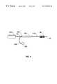
- FIG. 1is a cross-sectional view of the single-ended optical device of the present invention.
- FIG. 2is a cross-sectional view of the single-ended optical device of the present invention having a masked reflector serving as the mode stripper and the reflector.
- FIG. 3shows the modified surface region as an etched portion of the optical waveguide.
- FIG. 4depicts a single-ended optical fiber arrangement.
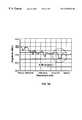
- FIG. 5Ais a spectral plot for a long period grating in transmission mode.
- FIG. 5Bis a spectral plot for a long period grating in reflection mode when a mode stripper is used.
- FIG. 5Cis a spectral plot for a long period grating in reflection without a mode stripper.
- FIG. 1depicts the single-ended optical device 10 of the present invention.
- the single-ended optical device 10comprises an optical waveguide 20 having at least one core mode 30 and a plurality of cladding modes 40 .
- the optical waveguide 20is any optical waveguide known to those skilled in the art.
- the optical waveguideis selected from the group consisting of: a planar optical waveguide; an integrated optical waveguide; and a fiber optic waveguide.
- the optical waveguideis a fiber optic waveguide as shown in FIG. 1-3.
- At least one long period grating 50is disposed within the optical waveguide 20 .
- FIG. 1shows a long period grating 50 disposed within the core 60 of the optical waveguide 20 .
- the long period grating 50is written into the core of the optical waveguide using standard techniques known to those skilled in the art.
- the resulting long period grating 50has a plurality of index perturbations spaced apart by a periodic distance A.
- the periodic distanceis 10 ⁇ m ⁇ 1500 ⁇ m.
- the periodic distance ⁇ between each perturbationdoes not have to be equidistant.
- the long period grating 50couples light from the core mode to the cladding modes.
- a reflector 70is positioned in an operable relationship to the long period grating 50 and functions to reflect a signal.
- a reflectoris defined as any element that is capable of reversing the direction of a propagating signal.
- the reflectoreliminates the need to write broadband gratings at the optical waveguide tip. Broadband gratings are sensitive to external perturbations, which are undesirable for the present application.
- the operable relationship between the reflector 70 and the long period grating 50is such that the reflector 70 is positioned at one end 80 of the optical waveguide 20 but proximate to the long period grating 50 .
- the distance between the reflector 70 and the long period grating 50is short (less than about 7.62 cm) thus requiring a mode stripper to remove the light from the optical waveguide. It is important that this distance remain as short as possible in order to keep the device compact.
- the end 80 of the optical waveguidemust be modified to make the core and cladding essentially or nearly flat. This modification process is any process wherein the core and the cladding are made relatively flat.
- the optical waveguidemay be cleaved or polished to expose the core and cladding. Regardless of the method used, the optical waveguide must be modified to make the core and the cladding into a relatively flat surface on which the reflector is deposited.
- the reflector 70is any reflector known to those skilled in the art. Specific examples of the reflector 70 include a broadface reflector which covers both the core and the cladding; a masked reflector which covers only the core of the optical waveguide; or an angled reflector.
- the reflectoris constructed from any metal or dielectric, stacked or multilayer, for filtering any wavelengths transmitted and/or reflected, known to those skilled in the art. In particular, gold works well for total reflection of the signal, but coatings are not limited to this.
- the essence of the inventionlies in the mode stripper 90 which is positioned after the long period grating 50 .
- the mode stripper 90removes the cladding modes or cladding mode light from the transmitted and reflected signal.
- a mode stripperis defined as any modification which is capable of changing the propagation conditions in the waveguide to remove propagating light in the cladding modes.
- mode strippersThere are several types of mode strippers. In FIG. 1, the mode stripper is depicted as a modified surface region 90 positioned between the long period grating 50 and the reflector 70 .
- the masked reflector 100consists of a reflector deposited on the endface of the optical waveguide's core and suppresses the reflection of the cladding modes.
- FIG. 3shows an embodiment where the modified surface region 90 is an etched section 130 of a fiber optic waveguide cladding.
- the diameter of the optical waveguide claddingis modified in a region after the long period grating 50 and a highly absorptive material 120 , such as a seeded epoxy (an epoxy with particulate dispersed in it), is deposited on the etched region.
- a highly absorptive material 120such as a seeded epoxy (an epoxy with particulate dispersed in it)
- This regionfunctions in combination with a reflector 70 to remove the cladding modes before light returns through the long period grating 50 .
- An alternative embodiment to that shown in FIG. 3is to taper a portion of the optical waveguide cladding instead of etching it.
- surface modification of the claddingcan be achieved by applying a matched index coating on a portion of the optical waveguide immediately following the long period grating as shown in FIG. 1 .
- the refractive index of the optical waveguide claddingis matched to the refractive index of the coating.
- the matched index coatinghas a refractive index approximately equal to the refractive index of the cladding.
- This matched index coatingis then disposed on a portion of the optical waveguide. Examples of materials which are suitable as matched index coatings include but are not limited to epoxies, acrylate coatings, and equivalents thereof.
- An alternative to applying a matched index coatingis to use an optically opaque material on a portion of the optical waveguide following the long period grating.
- the optically opaque materialdisplays certain characteristics at a specific operable spectral region. Examples of these types of materials include but are not limited to: seeded epoxies and equivalents thereof.
- the single-ended optical device 10is incorporated into an optical waveguide arrangement as shown in FIG. 4.
- a broadband light source 135is positioned at a first end of the optical waveguide 20 .
- a splitter 140having a first input 150 , a second input 160 , and at least one output 170 , is positioned between the broadband light source 135 and the long period grating 50 .
- a reflector 70is positioned after the long period grating 50 .
- the broadband light source 135is coupled to the first input 150 .
- a detector 180is coupled to the second input 160 . The detector 180 detects the reflected signal.
- Changes in any environmental parameter known to those skilled in the artmay be detected using the aforementioned arrangement.
- changes in environmental parameterssuch as but not limited to: temperature, strain, shape, pressure, moisture, corrosion, refractive index, presence of targets, and target concentration may be measured.
- lightis launched into the optical waveguide core.
- the lightcontacts the long period grating and is coupled to the cladding modes.
- the single-ended optical deviceis exposed to an environmental parameter at the long period grating.
- the lightis stripped from the cladding modes as it passes through the mode stripper and the remaining light is reflected back through the long period grating.
- the spectral profile of the reflected lightis then detected.
- a single-ended optical devicewas prepared from an optical fiber.
- a long period gratingwas written into Coming Flexcore 1060 single mode fiber.
- the gratingwas written using a frequency doubled argon-ion laser operating continuous wave (CW) with an average power of 110 mW at a wavelength of 244 nm.
- the fiberwas side-exposed through an amplitude mask with a period of 135 microns.
- CWcontinuous wave
- the acrylate coating on the fiberwas stripped by submerging a 2 cm segment in methylene chloride for 3 minutes.
- the gratingwas written in transmission and white light was propagated through the fiber and observed on an optical spectrum analyzer during the writing process. Total time of exposure was 25 minutes.
- the fiberwas then cleaved approximately 2 cm after the bare section containing the long period grating.
- the fiber after the long period gratingwas not stripped of its buffer jacket.
- the fiber endfacewas then coated with gold in an evaporation chamber. The thickness of the gold film on the endface was greater than 1 micron to ensure high reflectivity.
- the fiber devicewas then tested using a broadband 1550 LED source coupled to a 50/50 2 ⁇ 2 coupler.
- the long period grating, used in reflection,was connected to the output of the coupler as shown in FIG. 4 .
- the first two spectral plots shown in FIGS. 5A and 5Brepresent the long period grating spectrum in transmission mode (FIG. 5A) and also in reflection mode (FIG. 5 B).
- the last spectral plot shown in FIG. 5Crepresents an identical long period grating in reflection without the acrylate coating between the long period grating and the reflector. The lack of a clearly-defined long period grating profile shows that the mode stripper is required.
Landscapes
- Physics & Mathematics (AREA)
- General Physics & Mathematics (AREA)
- Optics & Photonics (AREA)
- Optical Couplings Of Light Guides (AREA)
Abstract
Description
Claims (49)
Priority Applications (1)
| Application Number | Priority Date | Filing Date | Title |
|---|---|---|---|
| US09/440,499US6275628B1 (en) | 1998-12-10 | 1999-11-15 | Single-ended long period grating optical device |
Applications Claiming Priority (2)
| Application Number | Priority Date | Filing Date | Title |
|---|---|---|---|
| US16006198P | 1998-12-10 | 1998-12-10 | |
| US09/440,499US6275628B1 (en) | 1998-12-10 | 1999-11-15 | Single-ended long period grating optical device |
Publications (1)
| Publication Number | Publication Date |
|---|---|
| US6275628B1true US6275628B1 (en) | 2001-08-14 |
Family
ID=26856563
Family Applications (1)
| Application Number | Title | Priority Date | Filing Date |
|---|---|---|---|
| US09/440,499Expired - Fee RelatedUS6275628B1 (en) | 1998-12-10 | 1999-11-15 | Single-ended long period grating optical device |
Country Status (1)
| Country | Link |
|---|---|
| US (1) | US6275628B1 (en) |
Cited By (111)
| Publication number | Priority date | Publication date | Assignee | Title |
|---|---|---|---|---|
| US6343168B1 (en)* | 1997-10-02 | 2002-01-29 | Luna Innovations, Inc. | Optical sensor arrangement |
| US20020183597A1 (en)* | 2001-04-25 | 2002-12-05 | Kaufman Kenton R. | Microsensor for physiological pressure measurement |
| US6522810B2 (en)* | 2000-10-31 | 2003-02-18 | Sumitomo Electric Industries, Ltd. | Optical loss filter |
| US20030169990A1 (en)* | 2000-08-03 | 2003-09-11 | Stephane Rio | Method for optical fibre re-cladding and resulting product |
| US20040001664A1 (en)* | 2002-06-27 | 2004-01-01 | Liwei Wang | Wafer level testing of optical components |
| US20040190812A1 (en)* | 2001-10-05 | 2004-09-30 | Barger Lee Allen | Refractive index probe apparatus and system |
| US20040218847A1 (en)* | 2003-03-19 | 2004-11-04 | Luna Innovations, Inc. | Fiber-optic apparatus and method for making simultaneous multiple parameter measurements |
| US6885795B1 (en) | 2002-05-31 | 2005-04-26 | Kotusa, Inc. | Waveguide tap monitor |
| US20050105841A1 (en)* | 2002-10-04 | 2005-05-19 | Shufang Luo | Devices, systems, and methods for sensing moisture |
| US20050254062A1 (en)* | 2003-11-06 | 2005-11-17 | Fortebio, Inc. | Fiber-optic assay apparatus based on phase-shift interferometry |
| US20060154320A1 (en)* | 2005-01-07 | 2006-07-13 | Fortebio, Inc. | Enzyme activity measurement using bio-layer interferometry |
| US20070148760A1 (en)* | 2005-12-22 | 2007-06-28 | Palo Alto Research Center Incorporated | Obtaining analyte information |
| US20070147728A1 (en)* | 2005-12-22 | 2007-06-28 | Palo Alto Research Center Incorporated | Providing light to channels or portions |
| US20070146704A1 (en)* | 2005-12-22 | 2007-06-28 | Palo Alto Research Center Incorporated | Sensing photon energies emanating from channels or moving objects |
| US20070147726A1 (en)* | 2005-12-22 | 2007-06-28 | Palo Alto Research Center Incorporated | Transmitting light with photon energy information |
| US20070147189A1 (en)* | 2005-12-22 | 2007-06-28 | Palo Alto Research Center Incorporated | Sensing photon energies of optical signals |
| US20070145236A1 (en)* | 2005-12-22 | 2007-06-28 | Palo Alto Research Center Incorporated | Photosensing throughout energy range and in subranges |
| US20070146888A1 (en)* | 2005-12-22 | 2007-06-28 | Palo Alto Research Center Incorporated | Propagating light to be sensed |
| US20070145249A1 (en)* | 2005-12-22 | 2007-06-28 | Palo Alto Research Center Incorporated | Sensing photons from objects in channels |
| US20070156019A1 (en)* | 2005-12-30 | 2007-07-05 | Larkin David Q | Robotic surgery system including position sensors using fiber bragg gratings |
| US20070217738A1 (en)* | 2006-03-16 | 2007-09-20 | Northrop Grumman Corporation | System and method to remove light from cladding |
| US20070265503A1 (en)* | 2006-03-22 | 2007-11-15 | Hansen Medical, Inc. | Fiber optic instrument sensing system |
| WO2007137429A1 (en)* | 2006-05-31 | 2007-12-06 | Itf Laboratories Inc. | Fiber bragg grating humidity sensor with enhanced sensitivity |
| US7308166B1 (en) | 2002-10-08 | 2007-12-11 | Kotura, Inc. | Coupling a light sensor array with an optical component |
| US20080084565A1 (en)* | 2006-10-05 | 2008-04-10 | General Electric Company | Interferometer-based real time early fouling detection system and method |
| US20080144039A1 (en)* | 2003-11-06 | 2008-06-19 | Fortebio, Inc. | Fiber-Optic Assay Apparatus Based on Phase-Shift Interferometry |
| US20080218770A1 (en)* | 2007-02-02 | 2008-09-11 | Hansen Medical, Inc. | Robotic surgical instrument and methods using bragg fiber sensors |
| US20080285909A1 (en)* | 2007-04-20 | 2008-11-20 | Hansen Medical, Inc. | Optical fiber shape sensing systems |
| CN100451609C (en)* | 2005-07-01 | 2009-01-14 | 重庆工学院 | Interference evanescent wave chemical and biological sensor and system with fibre-optical Michelson |
| US20090137952A1 (en)* | 2007-08-14 | 2009-05-28 | Ramamurthy Bhaskar S | Robotic instrument systems and methods utilizing optical fiber sensor |
| CN100561198C (en)* | 2005-07-01 | 2009-11-18 | 曾祥楷 | Fibre-optical microstructure Michelson interfere type surface plasma resonance chemistry and biology sensor and system |
| US20100093106A1 (en)* | 2006-09-14 | 2010-04-15 | Fortebio, Inc. | Amine-Reactive Biosensor |
| US8373860B2 (en) | 2008-02-01 | 2013-02-12 | Palo Alto Research Center Incorporated | Transmitting/reflecting emanating light with time variation |
| US8437582B2 (en) | 2005-12-22 | 2013-05-07 | Palo Alto Research Center Incorporated | Transmitting light with lateral variation |
| US8629981B2 (en) | 2008-02-01 | 2014-01-14 | Palo Alto Research Center Incorporated | Analyzers with time variation based on color-coded spatial modulation |
| US8647588B2 (en) | 2005-06-13 | 2014-02-11 | Pall Corporation | Tip tray assembly for optical sensors |
| US8723140B2 (en) | 2011-08-09 | 2014-05-13 | Palo Alto Research Center Incorporated | Particle analyzer with spatial modulation and long lifetime bioprobes |
| US8780339B2 (en) | 2009-07-15 | 2014-07-15 | Koninklijke Philips N.V. | Fiber shape sensing systems and methods |
| US8821799B2 (en) | 2007-01-26 | 2014-09-02 | Palo Alto Research Center Incorporated | Method and system implementing spatially modulated excitation or emission for particle characterization with enhanced sensitivity |
| US20140363125A1 (en)* | 2013-06-06 | 2014-12-11 | Prima Electro North America, LLC | Cladding mode stripper |
| US8989528B2 (en) | 2006-02-22 | 2015-03-24 | Hansen Medical, Inc. | Optical fiber grating sensors and methods of manufacture |
| US9029800B2 (en) | 2011-08-09 | 2015-05-12 | Palo Alto Research Center Incorporated | Compact analyzer with spatial modulation and multiple intensity modulated excitation sources |
| US9060678B2 (en) | 2006-06-13 | 2015-06-23 | Intuitive Surgical Operations, Inc. | Minimally invasive surgical system |
| US9164037B2 (en) | 2007-01-26 | 2015-10-20 | Palo Alto Research Center Incorporated | Method and system for evaluation of signals received from spatially modulated excitation and emission to accurately determine particle positions and distances |
| US9286673B2 (en) | 2012-10-05 | 2016-03-15 | Volcano Corporation | Systems for correcting distortions in a medical image and methods of use thereof |
| US9292918B2 (en) | 2012-10-05 | 2016-03-22 | Volcano Corporation | Methods and systems for transforming luminal images |
| US9301687B2 (en) | 2013-03-13 | 2016-04-05 | Volcano Corporation | System and method for OCT depth calibration |
| US9307926B2 (en) | 2012-10-05 | 2016-04-12 | Volcano Corporation | Automatic stent detection |
| US9307938B2 (en) | 2007-12-17 | 2016-04-12 | Palo Alto Research Center Incorporated | Controlling transfer of objects affecting optical characteristics |
| US9324141B2 (en) | 2012-10-05 | 2016-04-26 | Volcano Corporation | Removal of A-scan streaking artifact |
| US20160131848A1 (en)* | 2014-11-06 | 2016-05-12 | Huawei Technologies Co., Ltd. | Optical Waveguide Crossings |
| US9360630B2 (en) | 2011-08-31 | 2016-06-07 | Volcano Corporation | Optical-electrical rotary joint and methods of use |
| US9358076B2 (en) | 2011-01-20 | 2016-06-07 | Hansen Medical, Inc. | System and method for endoluminal and translumenal therapy |
| US9367965B2 (en) | 2012-10-05 | 2016-06-14 | Volcano Corporation | Systems and methods for generating images of tissue |
| US9383263B2 (en) | 2012-12-21 | 2016-07-05 | Volcano Corporation | Systems and methods for narrowing a wavelength emission of light |
| US9387048B2 (en) | 2011-10-14 | 2016-07-12 | Intuitive Surgical Operations, Inc. | Catheter sensor systems |
| CN105842147A (en)* | 2016-06-03 | 2016-08-10 | 安徽工业大学 | Reflective type long-cycle fiber grating sensor with single-end film plating and manufacturing technology and reinforcement corrosion monitoring method thereof |
| CN105842148A (en)* | 2016-06-03 | 2016-08-10 | 安徽工业大学 | Sensor for monitoring corrosion state of reinforcing steel bars, production process of sensor and monitoring method for corrosion of reinforcing steel bars |
| US9452276B2 (en) | 2011-10-14 | 2016-09-27 | Intuitive Surgical Operations, Inc. | Catheter with removable vision probe |
| CN105973279A (en)* | 2016-06-03 | 2016-09-28 | 安徽工业大学 | Single-end reflective long-period fiber grating sensor and manufacture process thereof |
| US9478940B2 (en) | 2012-10-05 | 2016-10-25 | Volcano Corporation | Systems and methods for amplifying light |
| US9486143B2 (en) | 2012-12-21 | 2016-11-08 | Volcano Corporation | Intravascular forward imaging device |
| US20160341916A1 (en)* | 2014-01-17 | 2016-11-24 | Empire Technology Development Llc | Optical fibers without cladding |
| US9596993B2 (en) | 2007-07-12 | 2017-03-21 | Volcano Corporation | Automatic calibration systems and methods of use |
| US9612105B2 (en) | 2012-12-21 | 2017-04-04 | Volcano Corporation | Polarization sensitive optical coherence tomography system |
| US9622706B2 (en) | 2007-07-12 | 2017-04-18 | Volcano Corporation | Catheter for in vivo imaging |
| US9709379B2 (en) | 2012-12-20 | 2017-07-18 | Volcano Corporation | Optical coherence tomography system that is reconfigurable between different imaging modes |
| US9730613B2 (en) | 2012-12-20 | 2017-08-15 | Volcano Corporation | Locating intravascular images |
| US9757149B2 (en) | 2006-06-13 | 2017-09-12 | Intuitive Surgical Operations, Inc. | Surgical system entry guide |
| US9770172B2 (en) | 2013-03-07 | 2017-09-26 | Volcano Corporation | Multimodal segmentation in intravascular images |
| US9851290B2 (en)* | 2015-06-22 | 2017-12-26 | Sharp Laboratories Of America, Inc. | Particle detector for particulate matter accumulated on a surface |
| US20170370697A1 (en)* | 2015-03-13 | 2017-12-28 | Olympus Corporation | Bending detecting system, light guide body, tubular apparatus, light detecting apparatus, light detecting method, and optical bending measuring apparatus |
| US9858668B2 (en) | 2012-10-05 | 2018-01-02 | Volcano Corporation | Guidewire artifact removal in images |
| US9867530B2 (en) | 2006-08-14 | 2018-01-16 | Volcano Corporation | Telescopic side port catheter device with imaging system and method for accessing side branch occlusions |
| US9962066B2 (en) | 2005-12-30 | 2018-05-08 | Intuitive Surgical Operations, Inc. | Methods and apparatus to shape flexible entry guides for minimally invasive surgery |
| WO2018138473A1 (en)* | 2017-01-30 | 2018-08-02 | Spi Lasers Uk Limited | Apparatus and method for optical isolation |
| US10058284B2 (en) | 2012-12-21 | 2018-08-28 | Volcano Corporation | Simultaneous imaging, monitoring, and therapy |
| US10070827B2 (en) | 2012-10-05 | 2018-09-11 | Volcano Corporation | Automatic image playback |
| US10130427B2 (en) | 2010-09-17 | 2018-11-20 | Auris Health, Inc. | Systems and methods for positioning an elongate member inside a body |
| US10166003B2 (en) | 2012-12-21 | 2019-01-01 | Volcano Corporation | Ultrasound imaging with variable line density |
| US10191220B2 (en) | 2012-12-21 | 2019-01-29 | Volcano Corporation | Power-efficient optical circuit |
| US10219887B2 (en) | 2013-03-14 | 2019-03-05 | Volcano Corporation | Filters with echogenic characteristics |
| US10219780B2 (en) | 2007-07-12 | 2019-03-05 | Volcano Corporation | OCT-IVUS catheter for concurrent luminal imaging |
| US10226597B2 (en) | 2013-03-07 | 2019-03-12 | Volcano Corporation | Guidewire with centering mechanism |
| US10238367B2 (en) | 2012-12-13 | 2019-03-26 | Volcano Corporation | Devices, systems, and methods for targeted cannulation |
| US10238837B2 (en) | 2011-10-14 | 2019-03-26 | Intuitive Surgical Operations, Inc. | Catheters with control modes for interchangeable probes |
| US10292677B2 (en) | 2013-03-14 | 2019-05-21 | Volcano Corporation | Endoluminal filter having enhanced echogenic properties |
| US10332228B2 (en) | 2012-12-21 | 2019-06-25 | Volcano Corporation | System and method for graphical processing of medical data |
| US10413317B2 (en) | 2012-12-21 | 2019-09-17 | Volcano Corporation | System and method for catheter steering and operation |
| US10420530B2 (en) | 2012-12-21 | 2019-09-24 | Volcano Corporation | System and method for multipath processing of image signals |
| US10426590B2 (en) | 2013-03-14 | 2019-10-01 | Volcano Corporation | Filters with echogenic characteristics |
| US10568586B2 (en) | 2012-10-05 | 2020-02-25 | Volcano Corporation | Systems for indicating parameters in an imaging data set and methods of use |
| US10595820B2 (en) | 2012-12-20 | 2020-03-24 | Philips Image Guided Therapy Corporation | Smooth transition catheters |
| US10638939B2 (en) | 2013-03-12 | 2020-05-05 | Philips Image Guided Therapy Corporation | Systems and methods for diagnosing coronary microvascular disease |
| US10667720B2 (en) | 2011-07-29 | 2020-06-02 | Auris Health, Inc. | Apparatus and methods for fiber integration and registration |
| US10682070B2 (en) | 2011-10-14 | 2020-06-16 | Intuitive Surgical Operations, Inc. | Electromagnetic sensor with probe and guide sensing elements |
| US10724082B2 (en) | 2012-10-22 | 2020-07-28 | Bio-Rad Laboratories, Inc. | Methods for analyzing DNA |
| US10758207B2 (en) | 2013-03-13 | 2020-09-01 | Philips Image Guided Therapy Corporation | Systems and methods for producing an image from a rotational intravascular ultrasound device |
| US10939826B2 (en) | 2012-12-20 | 2021-03-09 | Philips Image Guided Therapy Corporation | Aspirating and removing biological material |
| US10942022B2 (en) | 2012-12-20 | 2021-03-09 | Philips Image Guided Therapy Corporation | Manual calibration of imaging system |
| US10993694B2 (en) | 2012-12-21 | 2021-05-04 | Philips Image Guided Therapy Corporation | Rotational ultrasound imaging catheter with extended catheter body telescope |
| US11005230B2 (en)* | 2017-05-11 | 2021-05-11 | Fujikura Ltd. | Combiner, fiber laser device, and method for manufacturing combiner |
| US11026591B2 (en) | 2013-03-13 | 2021-06-08 | Philips Image Guided Therapy Corporation | Intravascular pressure sensor calibration |
| US11040140B2 (en) | 2010-12-31 | 2021-06-22 | Philips Image Guided Therapy Corporation | Deep vein thrombosis therapeutic methods |
| CN113376743A (en)* | 2021-06-22 | 2021-09-10 | 电子科技大学 | Spot-size converter based on long-period grating |
| US11141063B2 (en) | 2010-12-23 | 2021-10-12 | Philips Image Guided Therapy Corporation | Integrated system architectures and methods of use |
| US11154313B2 (en) | 2013-03-12 | 2021-10-26 | The Volcano Corporation | Vibrating guidewire torquer and methods of use |
| US11272845B2 (en) | 2012-10-05 | 2022-03-15 | Philips Image Guided Therapy Corporation | System and method for instant and automatic border detection |
| US11406498B2 (en) | 2012-12-20 | 2022-08-09 | Philips Image Guided Therapy Corporation | Implant delivery system and implants |
| US12201477B2 (en) | 2012-10-05 | 2025-01-21 | Philips Image Guided Therapy Corporation | Methods and systems for establishing parameters for three-dimensional imaging |
| US12343198B2 (en) | 2013-03-14 | 2025-07-01 | Philips Image Guided Therapy Corporation | Delivery catheter having imaging capabilities |
Citations (15)
| Publication number | Priority date | Publication date | Assignee | Title |
|---|---|---|---|---|
| US4844613A (en) | 1986-11-03 | 1989-07-04 | Stc Plc | Optical surface plasmon sensor device |
| US4929049A (en) | 1988-01-29 | 1990-05-29 | Fiberchem, Inc. | Fiber optic refractive index sensor using a metal clad |
| US4950883A (en) | 1988-12-27 | 1990-08-21 | United Technologies Corporation | Fiber optic sensor arrangement having reflective gratings responsive to particular wavelengths |
| US5026139A (en) | 1988-01-29 | 1991-06-25 | Fiberchem Inc. | Fiber optic refractive index sensor using metal cladding |
| US5048913A (en) | 1989-12-26 | 1991-09-17 | United Technologies Corporation | Optical waveguide embedded transverse spatial mode discrimination filter |
| US5064619A (en) | 1988-05-10 | 1991-11-12 | Amersham International Plc | Biological sensors |
| US5067788A (en) | 1990-03-21 | 1991-11-26 | Physical Optics Corporation | High modulation rate optical plasmon waveguide modulator |
| US5173747A (en) | 1990-09-20 | 1992-12-22 | Battelle Memorial Institute | Integrated optical directional-coupling refractometer apparatus |
| US5253037A (en) | 1992-08-04 | 1993-10-12 | Fci-Fiberchem, Inc. | Optimal length for refractive index sensors |
| US5359680A (en) | 1990-12-14 | 1994-10-25 | Thomson-Csf | Integrated electro-optical modulation device |
| US5430817A (en) | 1994-03-31 | 1995-07-04 | At&T Corp. | Optical systems and devices using long period spectral shaping devices |
| US5485277A (en) | 1994-07-26 | 1996-01-16 | Physical Optics Corporation | Surface plasmon resonance sensor and methods for the utilization thereof |
| US5492840A (en) | 1988-11-10 | 1996-02-20 | Pharmacia Biosensor Ab | Surface plasmon resonance sensor unit and its use in biosensor systems |
| US5641956A (en)* | 1996-02-02 | 1997-06-24 | F&S, Inc. | Optical waveguide sensor arrangement having guided modes-non guided modes grating coupler |
| US5864641A (en) | 1997-04-11 | 1999-01-26 | F&S, Inc. | Optical fiber long period sensor having a reactive coating |
- 1999
- 1999-11-15USUS09/440,499patent/US6275628B1/ennot_activeExpired - Fee Related
Patent Citations (15)
| Publication number | Priority date | Publication date | Assignee | Title |
|---|---|---|---|---|
| US4844613A (en) | 1986-11-03 | 1989-07-04 | Stc Plc | Optical surface plasmon sensor device |
| US4929049A (en) | 1988-01-29 | 1990-05-29 | Fiberchem, Inc. | Fiber optic refractive index sensor using a metal clad |
| US5026139A (en) | 1988-01-29 | 1991-06-25 | Fiberchem Inc. | Fiber optic refractive index sensor using metal cladding |
| US5064619A (en) | 1988-05-10 | 1991-11-12 | Amersham International Plc | Biological sensors |
| US5492840A (en) | 1988-11-10 | 1996-02-20 | Pharmacia Biosensor Ab | Surface plasmon resonance sensor unit and its use in biosensor systems |
| US4950883A (en) | 1988-12-27 | 1990-08-21 | United Technologies Corporation | Fiber optic sensor arrangement having reflective gratings responsive to particular wavelengths |
| US5048913A (en) | 1989-12-26 | 1991-09-17 | United Technologies Corporation | Optical waveguide embedded transverse spatial mode discrimination filter |
| US5067788A (en) | 1990-03-21 | 1991-11-26 | Physical Optics Corporation | High modulation rate optical plasmon waveguide modulator |
| US5173747A (en) | 1990-09-20 | 1992-12-22 | Battelle Memorial Institute | Integrated optical directional-coupling refractometer apparatus |
| US5359680A (en) | 1990-12-14 | 1994-10-25 | Thomson-Csf | Integrated electro-optical modulation device |
| US5253037A (en) | 1992-08-04 | 1993-10-12 | Fci-Fiberchem, Inc. | Optimal length for refractive index sensors |
| US5430817A (en) | 1994-03-31 | 1995-07-04 | At&T Corp. | Optical systems and devices using long period spectral shaping devices |
| US5485277A (en) | 1994-07-26 | 1996-01-16 | Physical Optics Corporation | Surface plasmon resonance sensor and methods for the utilization thereof |
| US5641956A (en)* | 1996-02-02 | 1997-06-24 | F&S, Inc. | Optical waveguide sensor arrangement having guided modes-non guided modes grating coupler |
| US5864641A (en) | 1997-04-11 | 1999-01-26 | F&S, Inc. | Optical fiber long period sensor having a reactive coating |
Non-Patent Citations (10)
| Title |
|---|
| A. Asseh et al.; "Fiber Optical Bragg Grating Refractometer"; Fiber and Integrated Optics; Apr. 18, 1997; pp. 51-62; vol. 17; Taylor & Francis, U.S.A. |
| A. M. Vengsarkar et al., "Long-Period Cladding-Mode-Coupled Fiber Gratings: Properties and Applications," 1995 Technical Digest Series, vol. 22, Sep. 9-11, 1995, pp. SaB2-1-SaB2-4. |
| A. M. Vengsarkar et al., "Long-Period Fiber Gratings as Band-Rejection Filters," Journal of Lightwave Technology, vol. 14, No. 1, Jan. 1996, pp. 58-65, U.S.A. |
| A. M. Vengsarkar et al., "Long-Period Fiber Gratings as Gain-Flattening and Laser Stabillizing Devices," Tenth International Conference on Integrated Optics and Optical Fiber Communication, vol. 5, Jun. 26-30, 1995, pp. 3-4. |
| A. M. Vengsarkar et al., "Long-Period Gratings as Band Rejection Filters," OFC '95, Feb. 26-Mar. 3, 1995, pp. PD4-1-PD4-5. |
| A.D. Kersey et al.; "Fiber Grating Sensors"; Journal of Lightwave Technology; Aug. 1997; pp. 1442-1463; vol. 15, No. 8; IEEE; U.S.A. |
| J.A. Greene et al.; "Grating-Based Optical Fiber Corrosion Sensors"; SPIE; Mar. 1997; pp. 260-266; vol. 3042; U.S.A. |
| K.O. Hill et al., "Photosensitivity in Optical Fiber Waveguides: Application to Reflection Filter Fabrication," Appl. Phys. Lett., 32 (10), May 15, 1978, pp. 647-649. |
| T. A. Tran et al., "Real-time Immunoassays Using Fiber Optic Long-Period Grating Sensors," Biomedical Sensing, Imaging, and Tracking Technologies I, Proceedings SPIE-The International Society for Optical Engineering, R.A. Lieberman et al., Eds., vol. 2676, Jan. 29-31, 1996, pp. 165-170, U.S.A. |
| V. Bhatia et al., "Optical Fiber Long-Period Grating Sensors," Lightnews, Winter 1995, pp. 6-11, U.S.A. |
Cited By (209)
| Publication number | Priority date | Publication date | Assignee | Title |
|---|---|---|---|---|
| US6343168B1 (en)* | 1997-10-02 | 2002-01-29 | Luna Innovations, Inc. | Optical sensor arrangement |
| US20030169990A1 (en)* | 2000-08-03 | 2003-09-11 | Stephane Rio | Method for optical fibre re-cladding and resulting product |
| US6915043B2 (en)* | 2000-08-03 | 2005-07-05 | Highwave Optical Technologies | Method of re-cladding an optical fiber and product thus obtained |
| US6522810B2 (en)* | 2000-10-31 | 2003-02-18 | Sumitomo Electric Industries, Ltd. | Optical loss filter |
| US20020183597A1 (en)* | 2001-04-25 | 2002-12-05 | Kaufman Kenton R. | Microsensor for physiological pressure measurement |
| US20040190812A1 (en)* | 2001-10-05 | 2004-09-30 | Barger Lee Allen | Refractive index probe apparatus and system |
| US6885795B1 (en) | 2002-05-31 | 2005-04-26 | Kotusa, Inc. | Waveguide tap monitor |
| US20040001664A1 (en)* | 2002-06-27 | 2004-01-01 | Liwei Wang | Wafer level testing of optical components |
| US6947622B2 (en) | 2002-06-27 | 2005-09-20 | Kotura, Inc. | Wafer level testing of optical components |
| US20050105841A1 (en)* | 2002-10-04 | 2005-05-19 | Shufang Luo | Devices, systems, and methods for sensing moisture |
| US6965708B2 (en) | 2002-10-04 | 2005-11-15 | Luna Innovations, Inc. | Devices, systems, and methods for sensing moisture |
| US7769254B1 (en) | 2002-10-08 | 2010-08-03 | Kotura, Inc. | Coupling a light sensor array with an optical component |
| US7308166B1 (en) | 2002-10-08 | 2007-12-11 | Kotura, Inc. | Coupling a light sensor array with an optical component |
| US20040218847A1 (en)* | 2003-03-19 | 2004-11-04 | Luna Innovations, Inc. | Fiber-optic apparatus and method for making simultaneous multiple parameter measurements |
| US6898337B2 (en) | 2003-03-19 | 2005-05-24 | Luna Innovations, Incorporated | Fiber-optic apparatus and method for making simultaneous multiple parameter measurements |
| US7728982B2 (en) | 2003-11-06 | 2010-06-01 | Fortebio, Inc. | Fiber-optic assay apparatus based on phase-shift interferometry |
| US20080144039A1 (en)* | 2003-11-06 | 2008-06-19 | Fortebio, Inc. | Fiber-Optic Assay Apparatus Based on Phase-Shift Interferometry |
| US20050254062A1 (en)* | 2003-11-06 | 2005-11-17 | Fortebio, Inc. | Fiber-optic assay apparatus based on phase-shift interferometry |
| US7656536B2 (en) | 2003-11-06 | 2010-02-02 | Fortebio, Inc. | Fiber-optic assay apparatus based on phase-shift interferometry |
| US20080186505A1 (en)* | 2003-11-06 | 2008-08-07 | Fortebio, Inc. | Fiber-optic assay apparatus based on phase-shift interferometry |
| US7394547B2 (en) | 2003-11-06 | 2008-07-01 | Fortebio, Inc. | Fiber-optic assay apparatus based on phase-shift interferometry |
| US20060154320A1 (en)* | 2005-01-07 | 2006-07-13 | Fortebio, Inc. | Enzyme activity measurement using bio-layer interferometry |
| US7445887B2 (en) | 2005-01-07 | 2008-11-04 | Fortebio, Inc. | Enzyme activity measurements using bio-layer interferometry |
| US8647588B2 (en) | 2005-06-13 | 2014-02-11 | Pall Corporation | Tip tray assembly for optical sensors |
| CN100561198C (en)* | 2005-07-01 | 2009-11-18 | 曾祥楷 | Fibre-optical microstructure Michelson interfere type surface plasma resonance chemistry and biology sensor and system |
| CN100451609C (en)* | 2005-07-01 | 2009-01-14 | 重庆工学院 | Interference evanescent wave chemical and biological sensor and system with fibre-optical Michelson |
| US7315667B2 (en) | 2005-12-22 | 2008-01-01 | Palo Alto Research Center Incorporated | Propagating light to be sensed |
| US7522786B2 (en) | 2005-12-22 | 2009-04-21 | Palo Alto Research Center Incorporated | Transmitting light with photon energy information |
| US20070148760A1 (en)* | 2005-12-22 | 2007-06-28 | Palo Alto Research Center Incorporated | Obtaining analyte information |
| US20070147728A1 (en)* | 2005-12-22 | 2007-06-28 | Palo Alto Research Center Incorporated | Providing light to channels or portions |
| US20070146704A1 (en)* | 2005-12-22 | 2007-06-28 | Palo Alto Research Center Incorporated | Sensing photon energies emanating from channels or moving objects |
| US8594470B2 (en) | 2005-12-22 | 2013-11-26 | Palo Alto Research Center Incorporated | Transmittting light with lateral variation |
| US7358476B2 (en) | 2005-12-22 | 2008-04-15 | Palo Alto Research Center Incorporated | Sensing photons from objects in channels |
| US7386199B2 (en) | 2005-12-22 | 2008-06-10 | Palo Alto Research Center Incorporated | Providing light to channels or portions |
| US8437582B2 (en) | 2005-12-22 | 2013-05-07 | Palo Alto Research Center Incorporated | Transmitting light with lateral variation |
| US7291824B2 (en) | 2005-12-22 | 2007-11-06 | Palo Alto Research Center Incorporated | Photosensing throughout energy range and in subranges |
| US20070147726A1 (en)* | 2005-12-22 | 2007-06-28 | Palo Alto Research Center Incorporated | Transmitting light with photon energy information |
| US7420677B2 (en) | 2005-12-22 | 2008-09-02 | Palo Alto Research Center Incorporated | Sensing photon energies of optical signals |
| US20070147189A1 (en)* | 2005-12-22 | 2007-06-28 | Palo Alto Research Center Incorporated | Sensing photon energies of optical signals |
| US20070145236A1 (en)* | 2005-12-22 | 2007-06-28 | Palo Alto Research Center Incorporated | Photosensing throughout energy range and in subranges |
| US7433552B2 (en) | 2005-12-22 | 2008-10-07 | Palo Alto Research Center Incorporated | Obtaining analyte information |
| US20070146888A1 (en)* | 2005-12-22 | 2007-06-28 | Palo Alto Research Center Incorporated | Propagating light to be sensed |
| US7547904B2 (en) | 2005-12-22 | 2009-06-16 | Palo Alto Research Center Incorporated | Sensing photon energies emanating from channels or moving objects |
| US20070145249A1 (en)* | 2005-12-22 | 2007-06-28 | Palo Alto Research Center Incorporated | Sensing photons from objects in channels |
| US10959607B2 (en) | 2005-12-30 | 2021-03-30 | Intuitive Surgical Operations, Inc. | Methods and apparatus to shape flexible entry guides for minimally invasive surgery |
| US9962066B2 (en) | 2005-12-30 | 2018-05-08 | Intuitive Surgical Operations, Inc. | Methods and apparatus to shape flexible entry guides for minimally invasive surgery |
| US11135023B2 (en) | 2005-12-30 | 2021-10-05 | Intuitive Surgical Operations, Inc. | Robotic surgery system including position sensors using fiber bragg gratings |
| US20070156019A1 (en)* | 2005-12-30 | 2007-07-05 | Larkin David Q | Robotic surgery system including position sensors using fiber bragg gratings |
| US9883914B2 (en) | 2005-12-30 | 2018-02-06 | Intuitive Surgical Operations, Inc. | Robotic surgery system including position sensors using fiber bragg gratings |
| US9039685B2 (en) | 2005-12-30 | 2015-05-26 | Intuitive Surgical Operations, Inc. | Robotic surgery system including position sensors using fiber bragg gratings |
| US9060793B2 (en) | 2005-12-30 | 2015-06-23 | Intuitive Surgical Operations, Inc. | Robotic surgery system including position sensor using fiber bragg gratings |
| US9066739B2 (en) | 2005-12-30 | 2015-06-30 | Intuitive Surgical Operations, Inc. | Robotic surgery system including position sensors using fiber bragg gratings |
| US7930065B2 (en) | 2005-12-30 | 2011-04-19 | Intuitive Surgical Operations, Inc. | Robotic surgery system including position sensors using fiber bragg gratings |
| US11712312B2 (en) | 2005-12-30 | 2023-08-01 | Intuitive Surgical Operations, Inc. | Robotic surgery system including position sensors using Fiber Bragg Gratings |
| US20110224685A1 (en)* | 2005-12-30 | 2011-09-15 | Intuitive Surgical Operations, Inc. | Robotic surgery system including position sensors using fiber bragg gratings |
| US20110224688A1 (en)* | 2005-12-30 | 2011-09-15 | Intuitive Surgical Operations, Inc. | Robotic surgery system including position sensors using fiber bragg gratings |
| US20110224825A1 (en)* | 2005-12-30 | 2011-09-15 | Intuitive Surgical Operations, Inc. | Robotic surgery system including position sensors using fiber bragg gratings |
| US20110224687A1 (en)* | 2005-12-30 | 2011-09-15 | Intuitive Surgical Operations, Inc. | Robotic surgery system including position sensors using fiber bragg gratings |
| US20110224686A1 (en)* | 2005-12-30 | 2011-09-15 | Intuitive Surgical Operations, Inc. | Robotic surgery system including position sensors using fiber bragg gratings |
| US12042120B2 (en) | 2005-12-30 | 2024-07-23 | Intuitive Surgical Operations, Inc. | Methods and apparatus to shape flexible entry guides for minimally invasive surgery |
| US12251181B2 (en) | 2005-12-30 | 2025-03-18 | Intuitive Surgical Operations, Inc. | Robotic surgery system including position sensors using fiber Bragg gratings |
| US9084624B2 (en) | 2005-12-30 | 2015-07-21 | Intuitive Surgical Operations, Inc. | Robotic surgery system including position sensors using fiber bragg gratings |
| US9241769B2 (en) | 2005-12-30 | 2016-01-26 | Intuitive Surgical Operations, Inc. | Robotic surgery system including position sensors using fiber bragg gratings |
| US9526583B2 (en) | 2005-12-30 | 2016-12-27 | Intuitive Surgical Operations, Inc. | Robotic surgery system including position sensors using fiber Bragg gratings |
| US9125679B2 (en) | 2005-12-30 | 2015-09-08 | Intuitive Surgical Operations, Inc. | Robotic surgery system including position sensors using fiber bragg gratings |
| US9101380B2 (en) | 2005-12-30 | 2015-08-11 | Intuitive Surgical Operations, Inc. | Robotic surgery system including position sensors using fiber Bragg gratings |
| US8989528B2 (en) | 2006-02-22 | 2015-03-24 | Hansen Medical, Inc. | Optical fiber grating sensors and methods of manufacture |
| US7349596B2 (en)* | 2006-03-16 | 2008-03-25 | Northrop Grumman Corporation | System and method to remove light from cladding |
| US20070217738A1 (en)* | 2006-03-16 | 2007-09-20 | Northrop Grumman Corporation | System and method to remove light from cladding |
| US20070265503A1 (en)* | 2006-03-22 | 2007-11-15 | Hansen Medical, Inc. | Fiber optic instrument sensing system |
| WO2007137429A1 (en)* | 2006-05-31 | 2007-12-06 | Itf Laboratories Inc. | Fiber bragg grating humidity sensor with enhanced sensitivity |
| US11666204B2 (en) | 2006-06-13 | 2023-06-06 | Intuitive Surgical Operations, Inc. | Minimally invasive surgical system |
| US12089809B2 (en) | 2006-06-13 | 2024-09-17 | Intuitive Surgical Operations, Inc. | Minimally invasive surgical system |
| US10398520B2 (en) | 2006-06-13 | 2019-09-03 | Intuitive Surgical Operations, Inc. | Minimally invasive surgical system |
| US11659978B2 (en) | 2006-06-13 | 2023-05-30 | Intuitive Surgical Operations, Inc. | Minimally invasive surgical system |
| US11957304B2 (en) | 2006-06-13 | 2024-04-16 | Intuitive Surgical Operations, Inc. | Minimally invasive surgical system |
| US11278364B2 (en) | 2006-06-13 | 2022-03-22 | Intuitive Surgical Operations, Inc. | Surgical system entry guide |
| US9060678B2 (en) | 2006-06-13 | 2015-06-23 | Intuitive Surgical Operations, Inc. | Minimally invasive surgical system |
| US9757149B2 (en) | 2006-06-13 | 2017-09-12 | Intuitive Surgical Operations, Inc. | Surgical system entry guide |
| US10456166B2 (en) | 2006-06-13 | 2019-10-29 | Intuitive Surgical Operations, Inc. | Surgical system entry guide |
| US9980630B2 (en) | 2006-06-13 | 2018-05-29 | Intuitive Surgical Operations, Inc. | Minimally invasive surgical system |
| US12207895B2 (en) | 2006-06-13 | 2025-01-28 | Intuitive Surgical Operations, Inc. | Surgical system entry guide |
| US12310552B2 (en) | 2006-06-13 | 2025-05-27 | Intuitive Surgical Operations, Inc. | Minimally invasive surgical system |
| US9867530B2 (en) | 2006-08-14 | 2018-01-16 | Volcano Corporation | Telescopic side port catheter device with imaging system and method for accessing side branch occlusions |
| US20100093106A1 (en)* | 2006-09-14 | 2010-04-15 | Fortebio, Inc. | Amine-Reactive Biosensor |
| US7428055B2 (en)* | 2006-10-05 | 2008-09-23 | General Electric Company | Interferometer-based real time early fouling detection system and method |
| US20080084565A1 (en)* | 2006-10-05 | 2008-04-10 | General Electric Company | Interferometer-based real time early fouling detection system and method |
| US9164037B2 (en) | 2007-01-26 | 2015-10-20 | Palo Alto Research Center Incorporated | Method and system for evaluation of signals received from spatially modulated excitation and emission to accurately determine particle positions and distances |
| US8821799B2 (en) | 2007-01-26 | 2014-09-02 | Palo Alto Research Center Incorporated | Method and system implementing spatially modulated excitation or emission for particle characterization with enhanced sensitivity |
| US9638637B2 (en) | 2007-01-26 | 2017-05-02 | Palo Alto Research Center Incorporated | Method and system implementing spatially modulated excitation or emission for particle characterization with enhanced sensitivity |
| US20080218770A1 (en)* | 2007-02-02 | 2008-09-11 | Hansen Medical, Inc. | Robotic surgical instrument and methods using bragg fiber sensors |
| US8811777B2 (en) | 2007-04-20 | 2014-08-19 | Koninklijke Philips Electronics N.V. | Optical fiber shape sensing systems |
| US8818143B2 (en) | 2007-04-20 | 2014-08-26 | Koninklijke Philips Electronics N.V. | Optical fiber instrument system for detecting twist of elongated instruments |
| US8705903B2 (en) | 2007-04-20 | 2014-04-22 | Koninklijke Philips N.V. | Optical fiber instrument system for detecting and decoupling twist effects |
| US20080285909A1 (en)* | 2007-04-20 | 2008-11-20 | Hansen Medical, Inc. | Optical fiber shape sensing systems |
| US8050523B2 (en) | 2007-04-20 | 2011-11-01 | Koninklijke Philips Electronics N.V. | Optical fiber shape sensing systems |
| US8515215B2 (en) | 2007-04-20 | 2013-08-20 | Koninklijke Philips Electronics N.V. | Optical fiber shape sensing systems |
| US20110172680A1 (en)* | 2007-04-20 | 2011-07-14 | Koninklijke Philips Electronics N.V. | Optical fiber shape sensing systems |
| US9622706B2 (en) | 2007-07-12 | 2017-04-18 | Volcano Corporation | Catheter for in vivo imaging |
| US10219780B2 (en) | 2007-07-12 | 2019-03-05 | Volcano Corporation | OCT-IVUS catheter for concurrent luminal imaging |
| US11350906B2 (en) | 2007-07-12 | 2022-06-07 | Philips Image Guided Therapy Corporation | OCT-IVUS catheter for concurrent luminal imaging |
| US9596993B2 (en) | 2007-07-12 | 2017-03-21 | Volcano Corporation | Automatic calibration systems and methods of use |
| US11067386B2 (en) | 2007-08-14 | 2021-07-20 | Koninklijke Philips N.V. | Instrument systems and methods utilizing optical fiber sensor |
| US10907956B2 (en) | 2007-08-14 | 2021-02-02 | Koninklijke Philips Electronics Nv | Instrument systems and methods utilizing optical fiber sensor |
| US8864655B2 (en) | 2007-08-14 | 2014-10-21 | Koninklijke Philips Electronics N.V. | Fiber optic instrument shape sensing system and method |
| US9441954B2 (en) | 2007-08-14 | 2016-09-13 | Koninklijke Philips Electronics N.V. | System and method for calibration of optical fiber instrument |
| US9726476B2 (en) | 2007-08-14 | 2017-08-08 | Koninklijke Philips Electronics N.V. | Fiber optic instrument orientation sensing system and method |
| US9500472B2 (en) | 2007-08-14 | 2016-11-22 | Koninklijke Philips Electronics N.V. | System and method for sensing shape of elongated instrument |
| US9500473B2 (en) | 2007-08-14 | 2016-11-22 | Koninklijke Philips Electronics N.V. | Optical fiber instrument system and method with motion-based adjustment |
| US9186047B2 (en) | 2007-08-14 | 2015-11-17 | Koninklijke Philips Electronics N.V. | Instrument systems and methods utilizing optical fiber sensor |
| US20090137952A1 (en)* | 2007-08-14 | 2009-05-28 | Ramamurthy Bhaskar S | Robotic instrument systems and methods utilizing optical fiber sensor |
| US9404734B2 (en) | 2007-08-14 | 2016-08-02 | Koninklijke Philips Electronics N.V. | System and method for sensing shape of elongated instrument |
| US9186046B2 (en) | 2007-08-14 | 2015-11-17 | Koninklijke Philips Electronics N.V. | Robotic instrument systems and methods utilizing optical fiber sensor |
| US9307938B2 (en) | 2007-12-17 | 2016-04-12 | Palo Alto Research Center Incorporated | Controlling transfer of objects affecting optical characteristics |
| US8629981B2 (en) | 2008-02-01 | 2014-01-14 | Palo Alto Research Center Incorporated | Analyzers with time variation based on color-coded spatial modulation |
| US8373860B2 (en) | 2008-02-01 | 2013-02-12 | Palo Alto Research Center Incorporated | Transmitting/reflecting emanating light with time variation |
| US8780339B2 (en) | 2009-07-15 | 2014-07-15 | Koninklijke Philips N.V. | Fiber shape sensing systems and methods |
| US10130427B2 (en) | 2010-09-17 | 2018-11-20 | Auris Health, Inc. | Systems and methods for positioning an elongate member inside a body |
| US10555780B2 (en) | 2010-09-17 | 2020-02-11 | Auris Health, Inc. | Systems and methods for positioning an elongate member inside a body |
| US11213356B2 (en) | 2010-09-17 | 2022-01-04 | Auris Health, Inc. | Systems and methods for positioning an elongate member inside a body |
| US12310669B2 (en) | 2010-09-17 | 2025-05-27 | Auris Health, Inc. | Systems and methods for positioning an elongate member inside a body |
| US11141063B2 (en) | 2010-12-23 | 2021-10-12 | Philips Image Guided Therapy Corporation | Integrated system architectures and methods of use |
| US11040140B2 (en) | 2010-12-31 | 2021-06-22 | Philips Image Guided Therapy Corporation | Deep vein thrombosis therapeutic methods |
| US9358076B2 (en) | 2011-01-20 | 2016-06-07 | Hansen Medical, Inc. | System and method for endoluminal and translumenal therapy |
| US10350390B2 (en) | 2011-01-20 | 2019-07-16 | Auris Health, Inc. | System and method for endoluminal and translumenal therapy |
| US11419518B2 (en) | 2011-07-29 | 2022-08-23 | Auris Health, Inc. | Apparatus and methods for fiber integration and registration |
| US10667720B2 (en) | 2011-07-29 | 2020-06-02 | Auris Health, Inc. | Apparatus and methods for fiber integration and registration |
| US8723140B2 (en) | 2011-08-09 | 2014-05-13 | Palo Alto Research Center Incorporated | Particle analyzer with spatial modulation and long lifetime bioprobes |
| US9029800B2 (en) | 2011-08-09 | 2015-05-12 | Palo Alto Research Center Incorporated | Compact analyzer with spatial modulation and multiple intensity modulated excitation sources |
| US9360630B2 (en) | 2011-08-31 | 2016-06-07 | Volcano Corporation | Optical-electrical rotary joint and methods of use |
| US9452276B2 (en) | 2011-10-14 | 2016-09-27 | Intuitive Surgical Operations, Inc. | Catheter with removable vision probe |
| US10682070B2 (en) | 2011-10-14 | 2020-06-16 | Intuitive Surgical Operations, Inc. | Electromagnetic sensor with probe and guide sensing elements |
| US12127797B2 (en) | 2011-10-14 | 2024-10-29 | Intuitive Surgical Operations, Inc. | Catheter sensor systems |
| US10744303B2 (en) | 2011-10-14 | 2020-08-18 | Intuitive Surgical Operations, Inc. | Catheters with control modes for interchangeable probes |
| US10653866B2 (en) | 2011-10-14 | 2020-05-19 | Intuitive Surgical Operations, Inc. | Catheter with removable vision probe |
| US10568700B2 (en) | 2011-10-14 | 2020-02-25 | Intuitive Surgical Operations, Inc. | Catheter sensor systems |
| US11918340B2 (en) | 2011-10-14 | 2024-03-05 | Intuitive Surgical Opeartions, Inc. | Electromagnetic sensor with probe and guide sensing elements |
| US10238837B2 (en) | 2011-10-14 | 2019-03-26 | Intuitive Surgical Operations, Inc. | Catheters with control modes for interchangeable probes |
| US9387048B2 (en) | 2011-10-14 | 2016-07-12 | Intuitive Surgical Operations, Inc. | Catheter sensor systems |
| US12390618B2 (en) | 2011-10-14 | 2025-08-19 | Intuitive Surgical Operations, Inc. | Catheters with control modes for interchangeable probes |
| US11684758B2 (en) | 2011-10-14 | 2023-06-27 | Intuitive Surgical Operations, Inc. | Catheter with removable vision probe |
| US9478940B2 (en) | 2012-10-05 | 2016-10-25 | Volcano Corporation | Systems and methods for amplifying light |
| US11272845B2 (en) | 2012-10-05 | 2022-03-15 | Philips Image Guided Therapy Corporation | System and method for instant and automatic border detection |
| US9367965B2 (en) | 2012-10-05 | 2016-06-14 | Volcano Corporation | Systems and methods for generating images of tissue |
| US11890117B2 (en) | 2012-10-05 | 2024-02-06 | Philips Image Guided Therapy Corporation | Systems for indicating parameters in an imaging data set and methods of use |
| US11864870B2 (en) | 2012-10-05 | 2024-01-09 | Philips Image Guided Therapy Corporation | System and method for instant and automatic border detection |
| US10568586B2 (en) | 2012-10-05 | 2020-02-25 | Volcano Corporation | Systems for indicating parameters in an imaging data set and methods of use |
| US11510632B2 (en) | 2012-10-05 | 2022-11-29 | Philips Image Guided Therapy Corporation | Systems for indicating parameters in an imaging data set and methods of use |
| US10070827B2 (en) | 2012-10-05 | 2018-09-11 | Volcano Corporation | Automatic image playback |
| US9324141B2 (en) | 2012-10-05 | 2016-04-26 | Volcano Corporation | Removal of A-scan streaking artifact |
| US12201477B2 (en) | 2012-10-05 | 2025-01-21 | Philips Image Guided Therapy Corporation | Methods and systems for establishing parameters for three-dimensional imaging |
| US9307926B2 (en) | 2012-10-05 | 2016-04-12 | Volcano Corporation | Automatic stent detection |
| US9858668B2 (en) | 2012-10-05 | 2018-01-02 | Volcano Corporation | Guidewire artifact removal in images |
| US9292918B2 (en) | 2012-10-05 | 2016-03-22 | Volcano Corporation | Methods and systems for transforming luminal images |
| US9286673B2 (en) | 2012-10-05 | 2016-03-15 | Volcano Corporation | Systems for correcting distortions in a medical image and methods of use thereof |
| US10724082B2 (en) | 2012-10-22 | 2020-07-28 | Bio-Rad Laboratories, Inc. | Methods for analyzing DNA |
| US10238367B2 (en) | 2012-12-13 | 2019-03-26 | Volcano Corporation | Devices, systems, and methods for targeted cannulation |
| US9730613B2 (en) | 2012-12-20 | 2017-08-15 | Volcano Corporation | Locating intravascular images |
| US10939826B2 (en) | 2012-12-20 | 2021-03-09 | Philips Image Guided Therapy Corporation | Aspirating and removing biological material |
| US11141131B2 (en) | 2012-12-20 | 2021-10-12 | Philips Image Guided Therapy Corporation | Smooth transition catheters |
| US11892289B2 (en) | 2012-12-20 | 2024-02-06 | Philips Image Guided Therapy Corporation | Manual calibration of imaging system |
| US10595820B2 (en) | 2012-12-20 | 2020-03-24 | Philips Image Guided Therapy Corporation | Smooth transition catheters |
| US9709379B2 (en) | 2012-12-20 | 2017-07-18 | Volcano Corporation | Optical coherence tomography system that is reconfigurable between different imaging modes |
| US11406498B2 (en) | 2012-12-20 | 2022-08-09 | Philips Image Guided Therapy Corporation | Implant delivery system and implants |
| US10942022B2 (en) | 2012-12-20 | 2021-03-09 | Philips Image Guided Therapy Corporation | Manual calibration of imaging system |
| US10993694B2 (en) | 2012-12-21 | 2021-05-04 | Philips Image Guided Therapy Corporation | Rotational ultrasound imaging catheter with extended catheter body telescope |
| US10413317B2 (en) | 2012-12-21 | 2019-09-17 | Volcano Corporation | System and method for catheter steering and operation |
| US10191220B2 (en) | 2012-12-21 | 2019-01-29 | Volcano Corporation | Power-efficient optical circuit |
| US9383263B2 (en) | 2012-12-21 | 2016-07-05 | Volcano Corporation | Systems and methods for narrowing a wavelength emission of light |
| US11786213B2 (en) | 2012-12-21 | 2023-10-17 | Philips Image Guided Therapy Corporation | System and method for multipath processing of image signals |
| US10332228B2 (en) | 2012-12-21 | 2019-06-25 | Volcano Corporation | System and method for graphical processing of medical data |
| US10058284B2 (en) | 2012-12-21 | 2018-08-28 | Volcano Corporation | Simultaneous imaging, monitoring, and therapy |
| US10166003B2 (en) | 2012-12-21 | 2019-01-01 | Volcano Corporation | Ultrasound imaging with variable line density |
| US10420530B2 (en) | 2012-12-21 | 2019-09-24 | Volcano Corporation | System and method for multipath processing of image signals |
| US11253225B2 (en) | 2012-12-21 | 2022-02-22 | Philips Image Guided Therapy Corporation | System and method for multipath processing of image signals |
| US9612105B2 (en) | 2012-12-21 | 2017-04-04 | Volcano Corporation | Polarization sensitive optical coherence tomography system |
| US9486143B2 (en) | 2012-12-21 | 2016-11-08 | Volcano Corporation | Intravascular forward imaging device |
| US9770172B2 (en) | 2013-03-07 | 2017-09-26 | Volcano Corporation | Multimodal segmentation in intravascular images |
| US10226597B2 (en) | 2013-03-07 | 2019-03-12 | Volcano Corporation | Guidewire with centering mechanism |
| US12350018B2 (en) | 2013-03-12 | 2025-07-08 | Philips Image Guided Therapy Corporation | Systems and methods for diagnosing coronary microvascular disease |
| US11154313B2 (en) | 2013-03-12 | 2021-10-26 | The Volcano Corporation | Vibrating guidewire torquer and methods of use |
| US10638939B2 (en) | 2013-03-12 | 2020-05-05 | Philips Image Guided Therapy Corporation | Systems and methods for diagnosing coronary microvascular disease |
| US11026591B2 (en) | 2013-03-13 | 2021-06-08 | Philips Image Guided Therapy Corporation | Intravascular pressure sensor calibration |
| US9301687B2 (en) | 2013-03-13 | 2016-04-05 | Volcano Corporation | System and method for OCT depth calibration |
| US10758207B2 (en) | 2013-03-13 | 2020-09-01 | Philips Image Guided Therapy Corporation | Systems and methods for producing an image from a rotational intravascular ultrasound device |
| US10292677B2 (en) | 2013-03-14 | 2019-05-21 | Volcano Corporation | Endoluminal filter having enhanced echogenic properties |
| US10426590B2 (en) | 2013-03-14 | 2019-10-01 | Volcano Corporation | Filters with echogenic characteristics |
| US10219887B2 (en) | 2013-03-14 | 2019-03-05 | Volcano Corporation | Filters with echogenic characteristics |
| US12343198B2 (en) | 2013-03-14 | 2025-07-01 | Philips Image Guided Therapy Corporation | Delivery catheter having imaging capabilities |
| US20140363125A1 (en)* | 2013-06-06 | 2014-12-11 | Prima Electro North America, LLC | Cladding mode stripper |
| US9946040B2 (en)* | 2014-01-17 | 2018-04-17 | Empire Technology Development Llc | Optical fibers without cladding |
| US20160341916A1 (en)* | 2014-01-17 | 2016-11-24 | Empire Technology Development Llc | Optical fibers without cladding |
| US20160131848A1 (en)* | 2014-11-06 | 2016-05-12 | Huawei Technologies Co., Ltd. | Optical Waveguide Crossings |
| US9618698B2 (en)* | 2014-11-06 | 2017-04-11 | Huawei Technologies Co., Ltd. | Optical waveguide crossings |
| US10401140B2 (en)* | 2015-03-13 | 2019-09-03 | Olympus Corporation | Bending detecting system, light guide body, tubular apparatus, light detecting apparatus, light detecting method, and optical bending measuring apparatus |
| US20170370697A1 (en)* | 2015-03-13 | 2017-12-28 | Olympus Corporation | Bending detecting system, light guide body, tubular apparatus, light detecting apparatus, light detecting method, and optical bending measuring apparatus |
| US9851290B2 (en)* | 2015-06-22 | 2017-12-26 | Sharp Laboratories Of America, Inc. | Particle detector for particulate matter accumulated on a surface |
| CN105973279A (en)* | 2016-06-03 | 2016-09-28 | 安徽工业大学 | Single-end reflective long-period fiber grating sensor and manufacture process thereof |
| CN105842147A (en)* | 2016-06-03 | 2016-08-10 | 安徽工业大学 | Reflective type long-cycle fiber grating sensor with single-end film plating and manufacturing technology and reinforcement corrosion monitoring method thereof |
| CN105842148A (en)* | 2016-06-03 | 2016-08-10 | 安徽工业大学 | Sensor for monitoring corrosion state of reinforcing steel bars, production process of sensor and monitoring method for corrosion of reinforcing steel bars |
| CN105842147B (en)* | 2016-06-03 | 2019-02-19 | 安徽工业大学 | A single-ended coating reflection type long-period fiber grating sensor and its manufacturing process and steel corrosion monitoring method |
| CN105842148B (en)* | 2016-06-03 | 2019-02-26 | 安徽工业大学 | A sensor for monitoring the corrosion state of steel bars and its manufacturing process and method for monitoring the corrosion of steel bars |
| CN105973279B (en)* | 2016-06-03 | 2019-03-19 | 安徽工业大学 | The single-ended reflective long-period fiber grating sensor of one kind and its manufacture craft |
| CN110235040B (en)* | 2017-01-30 | 2021-07-13 | 通快激光英国有限公司 | Apparatus and method for optical isolation |
| US11050209B2 (en) | 2017-01-30 | 2021-06-29 | Spi Lasers Uk Limited | Apparatus and method for optical isolation |
| WO2018138473A1 (en)* | 2017-01-30 | 2018-08-02 | Spi Lasers Uk Limited | Apparatus and method for optical isolation |
| CN110235040A (en)* | 2017-01-30 | 2019-09-13 | 司浦爱激光技术英国有限公司 | For optoisolated device and method |
| US11005230B2 (en)* | 2017-05-11 | 2021-05-11 | Fujikura Ltd. | Combiner, fiber laser device, and method for manufacturing combiner |
| CN113376743A (en)* | 2021-06-22 | 2021-09-10 | 电子科技大学 | Spot-size converter based on long-period grating |
Similar Documents
| Publication | Publication Date | Title |
|---|---|---|
| US6275628B1 (en) | Single-ended long period grating optical device | |
| US4557552A (en) | Microbend optical fiber tapped delay line | |
| US4749248A (en) | Device for tapping radiation from, or injecting radiation into, single made optical fiber, and communication system comprising same | |
| US4918305A (en) | Fiber optic pressure sensor using pressure sensitive fiber different from input and output fibers | |
| US3814498A (en) | Integrated optical circuit devices employing optical gratings | |
| US6185358B1 (en) | Optical attenuator and method of manufacturing same | |
| US4986624A (en) | Optical fiber evanescent grating reflector | |
| AU739886B2 (en) | Method and apparatus for making continuous chirped fiber bragg gratings | |
| EP0289332A1 (en) | Optical device | |
| US7085452B1 (en) | Optical devices having WGM cavity coupled to side-polished port | |
| US4893894A (en) | Evanescent sensor | |
| JPH023A (en) | Method of accessing optical fiber circuit and connector plug thereof | |
| US5253037A (en) | Optimal length for refractive index sensors | |
| Svalgaard | Direct writing of planar waveguide power splitters and directional couplers using a focused ultraviolet laser beam | |
| US10598857B2 (en) | Techniques for reducing polarization, wavelength and temperature dependent loss, and wavelength passband width in fiberoptic components | |
| CN108844919A (en) | The reflection type inclined fiber grating index sensor of covering and production, measurement method | |
| US4398795A (en) | Fiber optic tap and method of fabrication | |
| EP0989422B1 (en) | Tapered optical fiber devices with variable index coatings for modifying guide properties of the fundamental mode | |
| JPH10170754A (en) | Optical waveguide | |
| CN113029216B (en) | Multi-parameter sensor based on coaxial dual-waveguide fiber | |
| KR100361441B1 (en) | tap coupler | |
| CN114623951A (en) | Interference sensor based on dislocation single mode-few mode optical fiber mode reflection and system thereof | |
| JP2000121852A (en) | Waveguide grating type dispersion compensator | |
| JP7006964B2 (en) | Optical fiber type measuring device and optical fiber type measuring method | |
| RU2312381C2 (en) | Optical fibers provided with lens by way of photopolymerization and optical components |
Legal Events
| Date | Code | Title | Description |
|---|---|---|---|
| AS | Assignment | Owner name:LUNA INNOVATIONS, INC., VIRGINIA Free format text:ASSIGNMENT OF ASSIGNORS INTEREST;ASSIGNORS:JONES, MARK E.;MURPHY, KENT A.;ELSTER, JENNIFER L.;AND OTHERS;REEL/FRAME:010698/0632;SIGNING DATES FROM 19991104 TO 19991105 | |
| FEPP | Fee payment procedure | Free format text:PAT HOLDER NO LONGER CLAIMS SMALL ENTITY STATUS, ENTITY STATUS SET TO UNDISCOUNTED (ORIGINAL EVENT CODE: STOL); ENTITY STATUS OF PATENT OWNER: LARGE ENTITY | |
| FPAY | Fee payment | Year of fee payment:4 | |
| FEPP | Fee payment procedure | Free format text:PAYOR NUMBER ASSIGNED (ORIGINAL EVENT CODE: ASPN); ENTITY STATUS OF PATENT OWNER: LARGE ENTITY | |
| FPAY | Fee payment | Year of fee payment:8 | |
| AS | Assignment | Owner name:HANSEN MEDICAL, INC., CALIFORNIA Free format text:SECURITY AGREEMENT;ASSIGNOR:LUNA INNOVATIONS INCORPORATED;REEL/FRAME:023792/0388 Effective date:20100112 Owner name:HANSEN MEDICAL, INC.,CALIFORNIA Free format text:SECURITY AGREEMENT;ASSIGNOR:LUNA INNOVATIONS INCORPORATED;REEL/FRAME:023792/0388 Effective date:20100112 | |
| AS | Assignment | Owner name:SILICON VALLEY BANK,MASSACHUSETTS Free format text:SECURITY AGREEMENT;ASSIGNOR:LUNA INNOVATIONS INCORPORATED;REEL/FRAME:023985/0718 Effective date:20100218 Owner name:SILICON VALLEY BANK, MASSACHUSETTS Free format text:SECURITY AGREEMENT;ASSIGNOR:LUNA INNOVATIONS INCORPORATED;REEL/FRAME:023985/0718 Effective date:20100218 | |
| REMI | Maintenance fee reminder mailed | ||
| LAPS | Lapse for failure to pay maintenance fees | ||
| LAPS | Lapse for failure to pay maintenance fees | Free format text:PATENT EXPIRED FOR FAILURE TO PAY MAINTENANCE FEES (ORIGINAL EVENT CODE: EXP.); ENTITY STATUS OF PATENT OWNER: LARGE ENTITY | |
| STCH | Information on status: patent discontinuation | Free format text:PATENT EXPIRED DUE TO NONPAYMENT OF MAINTENANCE FEES UNDER 37 CFR 1.362 | |
| FP | Lapsed due to failure to pay maintenance fee | Effective date:20130814 | |
| AS | Assignment | Owner name:LUNA INNOVATIONS INCORPORATED, VIRGINIA Free format text:RELEASE BY SECURED PARTY;ASSIGNOR:HANSEN MEDICAL, INC.;REEL/FRAME:034914/0407 Effective date:20110518 |