US6274511B1 - Method of forming junction-leakage free metal silicide in a semiconductor wafer by amorphization of refractory metal layer - Google Patents
Method of forming junction-leakage free metal silicide in a semiconductor wafer by amorphization of refractory metal layerDownload PDFInfo
- Publication number
- US6274511B1 US6274511B1US09/256,781US25678199AUS6274511B1US 6274511 B1US6274511 B1US 6274511B1US 25678199 AUS25678199 AUS 25678199AUS 6274511 B1US6274511 B1US 6274511B1
- Authority
- US
- United States
- Prior art keywords
- metal layer
- metal
- source
- gate
- drain junctions
- Prior art date
- Legal status (The legal status is an assumption and is not a legal conclusion. Google has not performed a legal analysis and makes no representation as to the accuracy of the status listed.)
- Expired - Lifetime
Links
- 229910052751metalInorganic materials0.000titleclaimsabstractdescription90
- 239000002184metalSubstances0.000titleclaimsabstractdescription90
- FVBUAEGBCNSCDD-UHFFFAOYSA-Nsilicide(4-)Chemical compound[Si-4]FVBUAEGBCNSCDD-UHFFFAOYSA-N0.000titleclaimsabstractdescription61
- 229910021332silicideInorganic materials0.000titleclaimsabstractdescription59
- 238000000034methodMethods0.000titleclaimsabstractdescription41
- 239000004065semiconductorSubstances0.000titleclaimsabstractdescription27
- 239000003870refractory metalSubstances0.000titledescription8
- 238000005280amorphizationMethods0.000titledescription3
- 229910017052cobaltInorganic materials0.000claimsabstractdescription60
- 239000010941cobaltSubstances0.000claimsabstractdescription60
- GUTLYIVDDKVIGB-UHFFFAOYSA-Ncobalt atomChemical compound[Co]GUTLYIVDDKVIGB-UHFFFAOYSA-N0.000claimsabstractdescription58
- 239000002019doping agentSubstances0.000claimsabstractdescription20
- 239000000463materialSubstances0.000claimsabstractdescription18
- 230000008569processEffects0.000claimsabstractdescription13
- 238000000137annealingMethods0.000claimsabstractdescription10
- 229910052710siliconInorganic materials0.000claimsdescription29
- 239000010703siliconSubstances0.000claimsdescription29
- 238000000151depositionMethods0.000claimsdescription10
- 239000010936titaniumSubstances0.000claimsdescription10
- RTAQQCXQSZGOHL-UHFFFAOYSA-NTitaniumChemical compound[Ti]RTAQQCXQSZGOHL-UHFFFAOYSA-N0.000claimsdescription9
- 229910052719titaniumInorganic materials0.000claimsdescription9
- 238000002513implantationMethods0.000claimsdescription8
- 150000002500ionsChemical class0.000claimsdescription8
- 229910052732germaniumInorganic materials0.000claimsdescription3
- GNPVGFCGXDBREM-UHFFFAOYSA-Ngermanium atomChemical compound[Ge]GNPVGFCGXDBREM-UHFFFAOYSA-N0.000claimsdescription3
- NRTOMJZYCJJWKI-UHFFFAOYSA-NTitanium nitrideChemical compound[Ti]#NNRTOMJZYCJJWKI-UHFFFAOYSA-N0.000claimsdescription2
- 230000003993interactionEffects0.000claimsdescription2
- 229910018999CoSi2Inorganic materials0.000claims1
- 238000009792diffusion processMethods0.000abstractdescription9
- 238000005468ion implantationMethods0.000abstractdescription7
- 238000012421spikingMethods0.000abstractdescription3
- XUIMIQQOPSSXEZ-UHFFFAOYSA-NSiliconChemical compound[Si]XUIMIQQOPSSXEZ-UHFFFAOYSA-N0.000description29
- 230000015572biosynthetic processEffects0.000description16
- 229910021420polycrystalline siliconInorganic materials0.000description10
- 229920005591polysiliconPolymers0.000description10
- 238000006243chemical reactionMethods0.000description8
- 230000008021depositionEffects0.000description7
- PXHVJJICTQNCMI-UHFFFAOYSA-NNickelChemical compound[Ni]PXHVJJICTQNCMI-UHFFFAOYSA-N0.000description6
- 230000008901benefitEffects0.000description5
- 238000005240physical vapour depositionMethods0.000description5
- 229910021341titanium silicideInorganic materials0.000description5
- 238000005229chemical vapour depositionMethods0.000description4
- 238000004151rapid thermal annealingMethods0.000description4
- 125000006850spacer groupChemical group0.000description4
- 229910021417amorphous siliconInorganic materials0.000description3
- 230000000694effectsEffects0.000description3
- 238000002955isolationMethods0.000description3
- 238000004519manufacturing processMethods0.000description3
- 150000002739metalsChemical class0.000description3
- 239000000758substrateSubstances0.000description3
- IJGRMHOSHXDMSA-UHFFFAOYSA-NAtomic nitrogenChemical compoundN#NIJGRMHOSHXDMSA-UHFFFAOYSA-N0.000description2
- KDLHZDBZIXYQEI-UHFFFAOYSA-NPalladiumChemical compound[Pd]KDLHZDBZIXYQEI-UHFFFAOYSA-N0.000description2
- -1TiSi2Chemical compound0.000description2
- 230000008030eliminationEffects0.000description2
- 238000003379elimination reactionMethods0.000description2
- 238000005516engineering processMethods0.000description2
- 238000001755magnetron sputter depositionMethods0.000description2
- 238000012986modificationMethods0.000description2
- 230000004048modificationEffects0.000description2
- 229910052759nickelInorganic materials0.000description2
- 150000004767nitridesChemical class0.000description2
- BASFCYQUMIYNBI-UHFFFAOYSA-NplatinumChemical compound[Pt]BASFCYQUMIYNBI-UHFFFAOYSA-N0.000description2
- 238000005477sputtering targetMethods0.000description2
- ZOXJGFHDIHLPTG-UHFFFAOYSA-NBoronChemical compound[B]ZOXJGFHDIHLPTG-UHFFFAOYSA-N0.000description1
- 229910005883NiSiInorganic materials0.000description1
- 229910052581Si3N4Inorganic materials0.000description1
- VYPSYNLAJGMNEJ-UHFFFAOYSA-NSilicium dioxideChemical compoundO=[Si]=OVYPSYNLAJGMNEJ-UHFFFAOYSA-N0.000description1
- QAOWNCQODCNURD-UHFFFAOYSA-NSulfuric acidChemical compoundOS(O)(=O)=OQAOWNCQODCNURD-UHFFFAOYSA-N0.000description1
- 229910008479TiSi2Inorganic materials0.000description1
- 238000010420art techniqueMethods0.000description1
- DFJQEGUNXWZVAH-UHFFFAOYSA-Nbis($l^{2}-silanylidene)titaniumChemical compound[Si]=[Ti]=[Si]DFJQEGUNXWZVAH-UHFFFAOYSA-N0.000description1
- 229910052796boronInorganic materials0.000description1
- 230000002939deleterious effectEffects0.000description1
- BHEPBYXIRTUNPN-UHFFFAOYSA-Nhydridophosphorus(.) (triplet)Chemical compound[PH]BHEPBYXIRTUNPN-UHFFFAOYSA-N0.000description1
- 239000007943implantSubstances0.000description1
- 229910021421monocrystalline siliconInorganic materials0.000description1
- 229910052757nitrogenInorganic materials0.000description1
- 239000012299nitrogen atmosphereSubstances0.000description1
- 229910052763palladiumInorganic materials0.000description1
- 150000002978peroxidesChemical class0.000description1
- 229910052697platinumInorganic materials0.000description1
- 239000000376reactantSubstances0.000description1
- HQVNEWCFYHHQES-UHFFFAOYSA-Nsilicon nitrideChemical compoundN12[Si]34N5[Si]62N3[Si]51N64HQVNEWCFYHHQES-UHFFFAOYSA-N0.000description1
- 229910052814silicon oxideInorganic materials0.000description1
Images

Classifications
- H—ELECTRICITY
- H01—ELECTRIC ELEMENTS
- H01L—SEMICONDUCTOR DEVICES NOT COVERED BY CLASS H10
- H01L21/00—Processes or apparatus adapted for the manufacture or treatment of semiconductor or solid state devices or of parts thereof
- H01L21/02—Manufacture or treatment of semiconductor devices or of parts thereof
- H01L21/04—Manufacture or treatment of semiconductor devices or of parts thereof the devices having potential barriers, e.g. a PN junction, depletion layer or carrier concentration layer
- H01L21/18—Manufacture or treatment of semiconductor devices or of parts thereof the devices having potential barriers, e.g. a PN junction, depletion layer or carrier concentration layer the devices having semiconductor bodies comprising elements of Group IV of the Periodic Table or AIIIBV compounds with or without impurities, e.g. doping materials
- H01L21/28—Manufacture of electrodes on semiconductor bodies using processes or apparatus not provided for in groups H01L21/20 - H01L21/268
- H01L21/283—Deposition of conductive or insulating materials for electrodes conducting electric current
- H01L21/285—Deposition of conductive or insulating materials for electrodes conducting electric current from a gas or vapour, e.g. condensation
- H01L21/28506—Deposition of conductive or insulating materials for electrodes conducting electric current from a gas or vapour, e.g. condensation of conductive layers
- H01L21/28512—Deposition of conductive or insulating materials for electrodes conducting electric current from a gas or vapour, e.g. condensation of conductive layers on semiconductor bodies comprising elements of Group IV of the Periodic Table
- H01L21/28518—Deposition of conductive or insulating materials for electrodes conducting electric current from a gas or vapour, e.g. condensation of conductive layers on semiconductor bodies comprising elements of Group IV of the Periodic Table the conductive layers comprising silicides
Definitions
- the present inventionrelates to the field of semiconductor device manufacturing, and more particularly, to the formation of low resistivity self-aligned silicide regions on the gate and source/drain junctions.
- silicideIn the manufacture of integrated circuits, a commonly used practice is to form silicide on source/drain regions and on polysilicon gates. This practice has become increasingly important for very high density devices where the feature size is reduced to a fraction of a micrometer. Silicide provides good ohmic contact, reduces the sheet resistivity of source/drain regions and polysilicon gates, increases the effective contact area, and provides an etch stop.
- Salicide processinginvolves the deposition of a metal that forms intermetallic with silicon (Si), but does not react with silicon oxide or silicon nitride.
- Common metals employed in salicide processingare titanium (Ti), cobalt (Co), and nickel (Ni). These common metals form low resistivity phases with silicon, such as TiSi 2 , CoSi 2 and NiSi. The metal is deposited with a uniform thickness across the entire semiconductor wafer.
- PVDphysical vapor deposition
- UHVultra-high vacuum
- DC magnetron sputtering systema commercially available ultra-high vacuum
- Depositionis performed after both gate etch and source/drain junction formation.
- the metalblankets the polysilicon gate electrode, the oxide spacers, the oxide isolation, and the exposed source and drain electrodes.
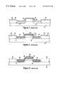
- FIG. 1A cross-section of an exemplary semiconductor wafer during one stage of a salicide formation process in accordance with the prior art techniques is depicted in FIG. 1 .
- a silicon substrate 10has been provided with the source/drain junctions 12 , 14 and a polysilicon gate 16 .
- Oxide spacers 18have been formed on the sides of the polysilicon gate 16 .
- the refractory metal layer 20comprising cobalt, for example, has been blanket deposited over the source/drain junctions 12 , 14 , the polysilicon gate 16 and the spacers 18 .
- the metal layer 20also blankets oxide isolation regions 22 that isolate the devices from one another.
- a first rapid thermal anneal (RTA) stepis then performed at a temperature of between about 450°-700° C. for a short period of time in a nitrogen atmosphere.
- the nitrogenreacts with the metal to form a metal nitride at the surface of the metal, while the metal reacts with silicon and forms silicide in those regions where it comes in direct contact with the silicon.
- the reaction of the metal with the siliconforms a silicide 24 on the gate 16 and source/drain regions 12 , 14 , as depicted in FIG. 2 .
- any metal that is unreactedis stripped away using a wet etch process that is selective to the silicide.
- a second, higher temperature rapid thermal anneal stepfor example above 700° C., is applied to form a lower resistance silicide phase of the metal silicide.
- the resultant structureis depicted in FIG. 3 in which the higher resistivity metal silicide 24 has been transformed to the lowest resistivity phase metal silicide 26 .
- the metalis cobalt
- the higher resistivity phaseis CoSi and the lowest resistivity phase is CoSi 2 .
- the silicideforms simultaneously over both regions so that this method is described as “salicide” since the silicides formed over the polysilicon and single-crystal silicon are self-aligned to each other.
- Titaniumis currently the most prevalent metal used in the integrated circuit industry, largely because titanium is already employed in other areas of 0.5 micron CMOS logic technologies.
- the so-called “C49” crystallographic titanium phaseis formed, and the lower resistance “C54” phase forms during the second rapid thermal anneal step.
- the titanium silicide sheet resistancerises dramatically due to narrow-line effects. This is described in European Publication No. 0651076.
- Cobalt silicide (CoSi 2 )has been introduced by several integrated circuit manufacturers as the replacement for titanium silicide. Since cobalt silicide forms by a diffusion reaction, it does not display the narrow-line effects observed with titanium silicide that forms by nucleation-and-growth.
- cobalt silicideprovides low resistivity, allows lower-temperature processing, has a reduced tendency for forming diode-like interfaces, and etchants for cobalt are stable and can be stored in premixed form indefinitely.
- junction leakagewhich occurs when cobalt silicide is formed such that it extends to the bottom and beyond of the source and drain junctions.
- An example of this occurrenceis depicted in FIG. 3 .
- One of the sources of this problemis roughness at the interface of the cobalt silicide and the silicon.
- the interface roughnessmay be related to grain boundary stress induced cobalt diffusion.
- Cobaltis the diffusing species in the initial reaction with silicon in a first annealing step to form the monosilicide, CoSi. Grain boundary stress in cobalt creates fast diffusion paths that lead to inhomogeneities in the formed silicide.
- a second annealing stepis performed to form the lower resistivity phase disilicide CoSi 2 , the silicide extends even further downwards towards the bottom of the source and drain junctions, and possibly through them.
- the rough interface and spike formationcauses CoSi 2 induced excess junction leakage, which is related to the grain boundary stress induced cobalt diffusion.
- One way to account for this problemis to make the junctions deeper, so that the uneven silicide will not reach the bottom of the source and drain junctions. Making the junctions deeper, however, negatively impacts device performance.
- embodiments of the present inventionwhich provide a method of forming ultra-shallow junctions in a semiconductor wafer with reduced junction leakage arising from a silicidation process.
- the gate and the source/drain junctionsare formed and a metal layer having grain boundaries is deposited over the gate and source/drain junctions.
- the grain boundaries in the metal layerare then substantially eliminated and grain boundary induced stress is released.
- Annealingis then performed to form metal silicide regions on the gate and source/drain junctions.
- the metal layercomprises cobalt and the step of substantially eliminating the grain boundaries includes amorphizing the cobalt by ion implantation of either a dopant or a nondopant.
- the elimination of grain boundaries and release of grain boundary induced stressprevents grain boundary stress induced diffusion of the cobalt during the first phase of the silicidation process, in which cobalt is the diffusing species. This serves to prevent the formation of junction spikes, which cause junction leakage.
- the controllable nature of the interfaceallows ultra-shallow junctions to be formed, since there is a reduced risk of spikes extending to the bottom of the source/drain junctions.
- the present inventionthereby provides sufficient distance between the bottom of the silicide and the bottom of the source/drain junction so that there will be no junction leakage.
- Another embodiment of the present inventionwhich provides a method of forming silicide comprising depositing an anamorphous metal layer over a gate and source/drain junctions. The metal layer is then amorphized, followed by reacting the now amorphized metal layer with the gate and source/drain junctions to form metal silicide regions on the gate and source/drain junctions.
- FIG. 1is a cross-section of a portion of a semiconductor wafer processed in accordance with the prior art during one step of a salicide process.
- FIG. 2depicts the cross-section of FIG. 1 after a first rapid thermal anneal step to form a high resistivity metal silicide region in accordance with the prior art.
- FIG. 3is a cross-section of the semiconductor wafer of FIG. 2 following a selective etch of the non reacted refractory metal and a second rapid thermal annealing step to form lower resistivity metal silicide regions in accordance with the prior art, depicting an uneven silicide/silicon interface and spike formation.
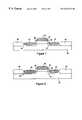
- FIG. 4is a cross-section of a portion of a semiconductor wafer prior to a salicidation process in accordance with certain embodiments of the present invention, following formation of the source and drain junctions.
- FIG. 5is a depiction of the semiconductor device of FIG. 4, following the deposition of a metal layer, such as cobalt, and during implantation of ions into the metal layer in accordance with certain embodiments of the present invention.
- a metal layersuch as cobalt
- FIG. 6depicts the semiconductor device of FIG. 5 following a first rapid thermal anneal step to form high resistivity metal silicide regions in accordance with embodiments of the present invention.
- FIG. 7depicts the semiconductor device of FIG. 6 following a selective etch that removes unreacted metal in accordance with embodiments of the present invention.
- FIG. 8is a depiction of the semiconductor device of FIG. 7 after a second rapid thermal annealing is performed to form lower resistivity metal silicide regions, in accordance with embodiments of the present invention.
- the present inventionallows ultra-shallow junction formation by releasing grain boundary stress to eliminate or reduce grain boundary stress induced metal diffusion in a silicidation process. This is accomplished in certain embodiments by ion implantation into a refractory metal layer following its deposition over the gate and source and drain junctions. This amorphizes the metal (which may be cobalt, for example) and thereby eliminates cobalt grain boundaries and releases the grain boundary stress. Fast outdiffusion of cobalt during silicidation is therefore avoided, preventing the formation of spikes that short-circuit the source and drain junctions. Since spike formation is avoided, the junctions may be designed to be shallower, leading to improved device performance.
- FIG. 4is a cross-section of a semiconductor device on a semiconductor wafer on which low resistivity metal silicide regions will be formed in accordance with embodiments of the present invention.
- a source junction 32 and a drain junction 34are formed within a silicon substrate 30 .
- a gate etchhas produced a gate 36 .
- Oxide (or nitride) spacers 38are provided on the sides of the polysilicon gate electrode 36 .
- Oxide isolation (such as LOCOS) regions 40isolate individual semiconductor devices from each other.
- a layer of refractory metal 42is then deposited uniformly across the entire wafer, preferably using physical vapor deposition from an ultra-pure sputtering target and a commercially available ultra-high-vacuum, multi-chamber, DC magnetron sputtering system.
- the metalis cobalt (Co), and the metal layer is deposited as a textured film.
- Cobalthas a number of advantages over other types of metals. For example, in comparison to silicon, titanium silicide sheet resistance rises dramatically due to narrow-line effects.
- cobalt silicideSince the low resistivity phase of cobalt silicide forms by a diffusion reaction rather than nucleation-and-growth as in the low resistivity phase of titanium silicide, cobalt silicide has been introduced by several integrated circuit manufacturers as the replacement for titanium. However, the use of cobalt in layer 42 as a refractory metal is exemplary only. Another example of a metal that is the diffusing species in the first phase of a silicidation process is nickel (Ni).
- cobaltis not currently available in the form of amorphous sputter targets. Furthermore, there is currently no known manufacturable chemical vapor deposition (CVD) process for the deposition of amorphous cobalt. This means that the cobalt layer 42 that is deposited on the gate 36 and source and drain junctions 32 , 34 will exhibit grain boundaries. The stress at these grain boundaries undesirably allows fast outdiffusion of cobalt during a first annealing step during which the higher resistivity phase cobalt silicide, CoSi, is formed.
- CVDchemical vapor deposition
- Cobaltis the diffusing species in a first reaction to form the higher resistivity phase of the silicide, while silicon is the diffusing species in a second reaction to form the lower resistivity phase of the silicide, CoSi 2 .
- the fast outdiffusion of cobalt at the grain boundaries during the formation of the CoSicreates spikes at these grain boundaries, causing junction leakage.
- the present inventionprevents the fast outdiffusion of cobalt by amorphizing the cobalt layer to release the grain boundary stress. This overcomes the disadvantages of presently available deposited cobalt layers, which are anamorphous. In certain preferred embodiments, the amorphization is accomplished by ion implantation.
- FIG. 5schematically depicts the ion implantation of a suitable implant material into the metal (e.g. cobalt) layer 42 .
- the materialmay be a non-dopant, such as silicon or germanium, or a dopant, such as boron or phosphorous, although the invention is not limited to these exemplary materials.
- the depth of the amorphous regionis very controllable, and depends on the implantation energy.
- Gemay be implanted at a concentration of 1 ⁇ 10 5 cm ⁇ 2 and with an energy of 60 keV. This will amorphize the entire depth of the cobalt layer 42 , assuming an exemplary layer depth of approximately 100 ⁇ .
- the implanting energyis set so as to amorphize the silicon ( 32 , 34 , 36 ) directly beneath the cobalt layer 42 .
- Thisadvantageously mixes the two reactants, cobalt and silicide, to further homogenize the interface and reduce the risk of spike formation during silicidation.
- Gemay be implanted at a concentration of 1 ⁇ 10 15 cm ⁇ 2 and with an energy of 80 keV. This will amorphize the silicon to a depth of about 50 ⁇ , assuming the cobalt layer 42 has a thickness of about 100 ⁇ .
- a non-dopant materialsuch as germanium or silicon
- an unmasked implantation proceduremay be performed.
- the non-dopant materialwill not have deleterious effects on other structures on the wafer.
- a masked implantation procedureis employed when the material to be implanted is a dopant, so that the metal layer 42 is doped only over those areas in which it is desirable to dope, such as the gate 36 and the source and drain junctions 32 , 34 .
- the dopantsare outdiffused from the metal layer into the source and drain junctions 32 , 34 .
- the outdiffusionmay be achieved during the annealing steps employed to form the silicide.
- the primary doping of these regionsmay be achieved using the dopants implanted in the metal layer in accordance with the present invention, if no doping was performed prior to the deposition of the metal layer 42 .
- the dopantsmay be used to enhance previous doping of these regions.
- the interface 37may be made relatively smooth, so that the amorphous silicon region 35 is of substantially uniform thickness. This is advantageous since the thickness of the CoSi layer, and the later formed CoSi 2 layer are determined by the thickness of the amorphous silicon region 35 . The more uniform the amorphous silicon region 35 , the more uniform the interface between the CoSi 2 layer and the silicon region 35 .
- a capping layer 45may be deposited to cap the middle layer 42 after the grain boundaries are eliminated.
- the capping layer 45is depicted in FIG. 6 .
- the capping layer 45prevents interaction with an ambient during the annealing.
- the capping layer 45may comprise at least one of titanium or titanium nitride, in preferred embodiments.
- the method of forming the capping layer 45 on the metal layer 42is conventional, such as by chemical vapor deposition (CVD) or physical vapor deposition (PVD), as examples.
- FIG. 6depicts the semiconductor device of FIG. 5 after the formation of high resistivity metal silicide regions.
- the high resistivity metal silicide regions 44are created by a rapid thermal anneal step.
- the high resistivity metal silicide regions 44may be made of cobalt silicide (CoSi), for example.
- the first rapid thermal annealing stepmay be performed by exposing the semiconductor wafer to a temperature between about 450° C. and about 600° C., and most preferably 500° C. The semiconductor wafer will be exposed for a relatively short time, for example, between about 5 and 90 seconds. In this step, cobalt is the diffusing species.
- the cobaltfast outdiffuses at the grain boundaries and there is grain boundary stress. Spikes may be created at the grain boundaries, leading to junction leakage.
- the amorphization of the cobalt in accordance with the present inventionsubstantially eliminates the cobalt grain boundaries and releases grain boundary induced stress.
- the silicon beneath the metal layer 42may also be amorphized, so that the metal and the silicon can be intermixed. As is apparent from FIG. 6, some of the silicon in the source and drain junctions 32 , 34 is consumed during the first rapid thermal annealing step to become part of the high resistivity metal silicide regions 44 . This is true also for the silicon in the polysilicon gate 36 .
- a selective etchis performed to remove any unreacted refractory metal, such as cobalt Typical etchants employed to remove unreacted cobalt are 3HCl:H 2 O 2 and H 2 SO 4 :H 2 O 2 . Removal of the unreacted metal by the peroxide solution leaves the silicide regions 44 intact. The resultant structure is depicted in FIG. 7 .
- a second rapid thermal anneal stepis now performed to produce lower resistivity metal silicide regions 46 , such as CoSi 2 , as depicted in FIG. 8 .
- the second rapid thermal anneal stepexposes the semiconductor wafer to a higher temperature than employed in the first rapid thermal anneal step.
- the temperature in this second rapid thermal anneal stepis between about 600° C. and about 850° C.
- the semiconductor waferis exposed to the high temperature for between about 5 and about 90 seconds.
- the higher resistivity monosilicidee.g. CoSi
- lower resistivity disilicidee.g. CoSi 2 .
- the CoSi 2 silicide/silicon interfacegenerally follows the CoSi silicide/silicon interface and is therefore relatively smooth. Spike formation is avoided, preventing junction leakage.
- the silicide/silicon interfaceis readily smoothed and spike formation prevented by the embodiments of the present invention that substantially eliminate cobalt grain boundaries and release cobalt grain boundary induced stress, there is little chance for the silicide to extend to the bottom and beyond of the junctions 32 , 34 .
- the controllability of the silicide depth and interface roughnessallows shallower junctions to be employed than otherwise possible, since deeper junctions providing a relatively large margin of safety below the silicide to avoid junction leakage are rendered unnecessary. With shallower junctions, improvements in device performance are achieved.
- the embodiments of the present inventionallow ultra-shallow junctions to be formed and employed in a semiconductor device with a low resistivity metal silicide, such as cobalt (CoSi 2 ) while avoiding junction leakage due to grain boundary stress induced junction spiking.
- a low resistivity metal silicidesuch as cobalt (CoSi 2 )
- Cobaltis employed as the refractory metal in forming the silicide.
- the present inventionfinds utility in other applications employing other materials in which a monosilicide is transferred to a disilicide, where the metal is the diffusing species in the first reaction, and silicon in the second reaction.
- the embodimentsdescribe ion implantation to amorphize the metal layer. This is also exemplary only, as the present invention is applicable to other methods of eliminating cobalt grain boundaries and releasing grain boundary induced stress to prevent spike formation.
Landscapes
- Engineering & Computer Science (AREA)
- Physics & Mathematics (AREA)
- Condensed Matter Physics & Semiconductors (AREA)
- General Physics & Mathematics (AREA)
- Manufacturing & Machinery (AREA)
- Computer Hardware Design (AREA)
- Microelectronics & Electronic Packaging (AREA)
- Power Engineering (AREA)
- Electrodes Of Semiconductors (AREA)
- Insulated Gate Type Field-Effect Transistor (AREA)
Abstract
Description
Claims (16)
Priority Applications (1)
| Application Number | Priority Date | Filing Date | Title |
|---|---|---|---|
| US09/256,781US6274511B1 (en) | 1999-02-24 | 1999-02-24 | Method of forming junction-leakage free metal silicide in a semiconductor wafer by amorphization of refractory metal layer |
Applications Claiming Priority (1)
| Application Number | Priority Date | Filing Date | Title |
|---|---|---|---|
| US09/256,781US6274511B1 (en) | 1999-02-24 | 1999-02-24 | Method of forming junction-leakage free metal silicide in a semiconductor wafer by amorphization of refractory metal layer |
Publications (1)
| Publication Number | Publication Date |
|---|---|
| US6274511B1true US6274511B1 (en) | 2001-08-14 |
Family
ID=22973562
Family Applications (1)
| Application Number | Title | Priority Date | Filing Date |
|---|---|---|---|
| US09/256,781Expired - LifetimeUS6274511B1 (en) | 1999-02-24 | 1999-02-24 | Method of forming junction-leakage free metal silicide in a semiconductor wafer by amorphization of refractory metal layer |
Country Status (1)
| Country | Link |
|---|---|
| US (1) | US6274511B1 (en) |
Cited By (19)
| Publication number | Priority date | Publication date | Assignee | Title |
|---|---|---|---|---|
| US6365446B1 (en)* | 2000-07-03 | 2002-04-02 | Chartered Semiconductor Manufacturing Ltd. | Formation of silicided ultra-shallow junctions using implant through metal technology and laser annealing process |
| US6468900B1 (en)* | 2000-12-06 | 2002-10-22 | Advanced Micro Devices, Inc. | Dual layer nickel deposition using a cobalt barrier to reduce surface roughness at silicide/junction interface |
| US6475908B1 (en)* | 2001-10-18 | 2002-11-05 | Chartered Semiconductor Manufacturing Ltd. | Dual metal gate process: metals and their silicides |
| US6506651B2 (en)* | 1999-07-26 | 2003-01-14 | Mitsubishi Denki Kabushiki Kaisha | Semiconductor device and manufacturing method thereof |
| US6518107B2 (en)* | 2001-02-16 | 2003-02-11 | Advanced Micro Devices, Inc. | Non-arsenic N-type dopant implantation for improved source/drain interfaces with nickel silicides |
| US6534402B1 (en)* | 2001-11-01 | 2003-03-18 | Winbond Electronics Corp. | Method of fabricating self-aligned silicide |
| US6537900B2 (en)* | 1999-04-27 | 2003-03-25 | Infineon Technologies Ag | Method for patterning a metal or metal silicide layer and a capacitor structure fabricated by the method |
| US20040137706A1 (en)* | 2003-01-10 | 2004-07-15 | Koichi Kaneko | Method of manufacturing semiconductor device |
| US6767812B2 (en)* | 2001-06-14 | 2004-07-27 | Oki Electric Industry Co., Ltd. | Method of forming CVD titanium film |
| US6773978B1 (en) | 2002-07-23 | 2004-08-10 | Advanced Micro Devices, Inc. | Methods for improved metal gate fabrication |
| US20040241971A1 (en)* | 2003-05-30 | 2004-12-02 | Karsten Wieczorek | Method of forming a metal silicide |
| US20050164460A1 (en)* | 2004-01-23 | 2005-07-28 | Agency For Science, Technology And Research | Salicide process for metal gate CMOS devices |
| US20050250326A1 (en)* | 2004-03-31 | 2005-11-10 | Nec Electronics Corporation | Method of manufacturing a semiconductor device |
| US20060172503A1 (en)* | 2005-02-01 | 2006-08-03 | Chan Lim | Methods of forming silicide |
| US20070020919A1 (en)* | 2005-07-01 | 2007-01-25 | Spansion Llc | Preamorphization to minimize void formation |
| CN1319127C (en)* | 2002-06-20 | 2007-05-30 | 上海华虹(集团)有限公司 | Method for semultaneous forming silicide and shallow junction |
| WO2013033943A1 (en)* | 2011-09-06 | 2013-03-14 | 深圳市华星光电技术有限公司 | Thin film transistor and manufacturing method thereof |
| US8492767B2 (en) | 2011-09-06 | 2013-07-23 | Shenzhen China Star Optoelectronics Technology Co., Ltd. | TFT substrate and manufacturing method thereof |
| TWI476820B (en)* | 2008-05-02 | 2015-03-11 | Varian Semiconductor Equipment | Method for improving the uniformity of chemical mechanical polishing flattening |
Citations (6)
| Publication number | Priority date | Publication date | Assignee | Title |
|---|---|---|---|---|
| US4683645A (en)* | 1985-06-28 | 1987-08-04 | Northern Telecom Limited | Process of fabricating MOS devices having shallow source and drain junctions |
| EP0651076A1 (en) | 1993-10-29 | 1995-05-03 | International Business Machines Corporation | Method for lowering the phase transformation temperature of a metal silicide |
| US5536684A (en)* | 1994-06-30 | 1996-07-16 | Intel Corporation | Process for formation of epitaxial cobalt silicide and shallow junction of silicon |
| US5998294A (en)* | 1998-04-29 | 1999-12-07 | The United States Of America As Represented By The Secretary Of The Navy | Method for forming improved electrical contacts on non-planar structures |
| US6037204A (en)* | 1998-08-07 | 2000-03-14 | Taiwan Semiconductor Manufacturing Company | Silicon and arsenic double implanted pre-amorphization process for salicide technology |
| US6072222A (en)* | 1998-05-18 | 2000-06-06 | Advanced Micro Devices, Inc. | Silicon implantation into selective areas of a refractory metal to reduce consumption of silicon-based junctions during salicide formation |
- 1999
- 1999-02-24USUS09/256,781patent/US6274511B1/ennot_activeExpired - Lifetime
Patent Citations (6)
| Publication number | Priority date | Publication date | Assignee | Title |
|---|---|---|---|---|
| US4683645A (en)* | 1985-06-28 | 1987-08-04 | Northern Telecom Limited | Process of fabricating MOS devices having shallow source and drain junctions |
| EP0651076A1 (en) | 1993-10-29 | 1995-05-03 | International Business Machines Corporation | Method for lowering the phase transformation temperature of a metal silicide |
| US5536684A (en)* | 1994-06-30 | 1996-07-16 | Intel Corporation | Process for formation of epitaxial cobalt silicide and shallow junction of silicon |
| US5998294A (en)* | 1998-04-29 | 1999-12-07 | The United States Of America As Represented By The Secretary Of The Navy | Method for forming improved electrical contacts on non-planar structures |
| US6072222A (en)* | 1998-05-18 | 2000-06-06 | Advanced Micro Devices, Inc. | Silicon implantation into selective areas of a refractory metal to reduce consumption of silicon-based junctions during salicide formation |
| US6037204A (en)* | 1998-08-07 | 2000-03-14 | Taiwan Semiconductor Manufacturing Company | Silicon and arsenic double implanted pre-amorphization process for salicide technology |
Non-Patent Citations (2)
| Title |
|---|
| "Doping Technologies", Materials and Bulk Processes, SIA Roundup, 1994, pp. 118-121. |
| "Ultra Shallow Junction Formation Using Diffusion from Silicides", H. Jiang et al., J. Electrochem. Soc., vol. 139, No. 1, Jan. 1992, pp. 196-218. |
Cited By (25)
| Publication number | Priority date | Publication date | Assignee | Title |
|---|---|---|---|---|
| US6537900B2 (en)* | 1999-04-27 | 2003-03-25 | Infineon Technologies Ag | Method for patterning a metal or metal silicide layer and a capacitor structure fabricated by the method |
| US6506651B2 (en)* | 1999-07-26 | 2003-01-14 | Mitsubishi Denki Kabushiki Kaisha | Semiconductor device and manufacturing method thereof |
| US6365446B1 (en)* | 2000-07-03 | 2002-04-02 | Chartered Semiconductor Manufacturing Ltd. | Formation of silicided ultra-shallow junctions using implant through metal technology and laser annealing process |
| US6468900B1 (en)* | 2000-12-06 | 2002-10-22 | Advanced Micro Devices, Inc. | Dual layer nickel deposition using a cobalt barrier to reduce surface roughness at silicide/junction interface |
| US6518107B2 (en)* | 2001-02-16 | 2003-02-11 | Advanced Micro Devices, Inc. | Non-arsenic N-type dopant implantation for improved source/drain interfaces with nickel silicides |
| US6767812B2 (en)* | 2001-06-14 | 2004-07-27 | Oki Electric Industry Co., Ltd. | Method of forming CVD titanium film |
| US6475908B1 (en)* | 2001-10-18 | 2002-11-05 | Chartered Semiconductor Manufacturing Ltd. | Dual metal gate process: metals and their silicides |
| US6534402B1 (en)* | 2001-11-01 | 2003-03-18 | Winbond Electronics Corp. | Method of fabricating self-aligned silicide |
| CN1319127C (en)* | 2002-06-20 | 2007-05-30 | 上海华虹(集团)有限公司 | Method for semultaneous forming silicide and shallow junction |
| US6773978B1 (en) | 2002-07-23 | 2004-08-10 | Advanced Micro Devices, Inc. | Methods for improved metal gate fabrication |
| US20040137706A1 (en)* | 2003-01-10 | 2004-07-15 | Koichi Kaneko | Method of manufacturing semiconductor device |
| US20040241971A1 (en)* | 2003-05-30 | 2004-12-02 | Karsten Wieczorek | Method of forming a metal silicide |
| DE10324657A1 (en)* | 2003-05-30 | 2005-01-05 | Advanced Micro Devices, Inc. (n.d.Ges.d. Staates Delaware), Sunnyvale | Process for the preparation of a metal silicide |
| DE10324657B4 (en)* | 2003-05-30 | 2009-01-22 | Advanced Micro Devices, Inc. (n.d.Ges.d. Staates Delaware), Sunnyvale | Process for the preparation of a metal silicide |
| US7067410B2 (en) | 2003-05-30 | 2006-06-27 | Advanced Micro Devices, Inc. | Method of forming a metal silicide |
| US20050164460A1 (en)* | 2004-01-23 | 2005-07-28 | Agency For Science, Technology And Research | Salicide process for metal gate CMOS devices |
| US7348273B2 (en)* | 2004-03-31 | 2008-03-25 | Nec Electronics Corporation | Method of manufacturing a semiconductor device |
| US20050250326A1 (en)* | 2004-03-31 | 2005-11-10 | Nec Electronics Corporation | Method of manufacturing a semiconductor device |
| US20060172503A1 (en)* | 2005-02-01 | 2006-08-03 | Chan Lim | Methods of forming silicide |
| US7399702B2 (en) | 2005-02-01 | 2008-07-15 | Infineon Technologies Ag | Methods of forming silicide |
| US20070020919A1 (en)* | 2005-07-01 | 2007-01-25 | Spansion Llc | Preamorphization to minimize void formation |
| US7361586B2 (en)* | 2005-07-01 | 2008-04-22 | Spansion Llc | Preamorphization to minimize void formation |
| TWI476820B (en)* | 2008-05-02 | 2015-03-11 | Varian Semiconductor Equipment | Method for improving the uniformity of chemical mechanical polishing flattening |
| WO2013033943A1 (en)* | 2011-09-06 | 2013-03-14 | 深圳市华星光电技术有限公司 | Thin film transistor and manufacturing method thereof |
| US8492767B2 (en) | 2011-09-06 | 2013-07-23 | Shenzhen China Star Optoelectronics Technology Co., Ltd. | TFT substrate and manufacturing method thereof |
Similar Documents
| Publication | Publication Date | Title |
|---|---|---|
| US6274511B1 (en) | Method of forming junction-leakage free metal silicide in a semiconductor wafer by amorphization of refractory metal layer | |
| JP3723359B2 (en) | Partial silicidation method for forming shallow source / drain junctions | |
| US6797602B1 (en) | Method of manufacturing a semiconductor device with supersaturated source/drain extensions and metal silicide contacts | |
| EP0800204B1 (en) | A process for device fabrication in which a thin layer of cobalt silicide is formed | |
| US6777275B1 (en) | Single anneal for dopant activation and silicide formation | |
| US6689688B2 (en) | Method and device using silicide contacts for semiconductor processing | |
| US5356837A (en) | Method of making epitaxial cobalt silicide using a thin metal underlayer | |
| US6150243A (en) | Shallow junction formation by out-diffusion from a doped dielectric layer through a salicide layer | |
| US6255214B1 (en) | Method of forming junction-leakage free metal silicide in a semiconductor wafer by amorphization of source and drain regions | |
| JP2720827B2 (en) | Method for manufacturing semiconductor device | |
| KR0148684B1 (en) | Manufacturing Method of Semiconductor Device | |
| US6383906B1 (en) | Method of forming junction-leakage free metal salicide in a semiconductor wafer with ultra-low silicon consumption | |
| US6165903A (en) | Method of forming ultra-shallow junctions in a semiconductor wafer with deposited silicon layer to reduce silicon consumption during salicidation | |
| US6281556B1 (en) | Process for forming a low resistivity titanium silicide layer on a silicon semiconductor substrate and the resulting device | |
| US6156615A (en) | Method for decreasing the contact resistance of silicide contacts by retrograde implantation of source/drain regions | |
| US6486062B1 (en) | Selective deposition of amorphous silicon for formation of nickel silicide with smooth interface on N-doped substrate | |
| US6297148B1 (en) | Method of forming a silicon bottom anti-reflective coating with reduced junction leakage during salicidation | |
| EP0736224B1 (en) | Method of forming a thermally stable silicide | |
| US6316362B1 (en) | Method for manufacturing semiconductor device | |
| KR100235941B1 (en) | Semiconductor device manufacturing method | |
| KR100273271B1 (en) | Fabricating method of silicide | |
| JPH06196687A (en) | Manufacture of semiconductor device | |
| US6049133A (en) | Semiconductor fabrication employing concurrent diffusion barrier and salicide formation | |
| US6777300B2 (en) | Method to improve silicide formation on polysilicon | |
| KR19990001016A (en) | Method of manufacturing transistor of semiconductor device |
Legal Events
| Date | Code | Title | Description |
|---|---|---|---|
| AS | Assignment | Owner name:ADVANCED MICRO DEVICES, INC., CALIFORNIA Free format text:ASSIGNMENT OF ASSIGNORS INTEREST;ASSIGNORS:WIECZOREK, KARSTEN;KEPLER, NICK;BESSER, PAUL R.;REEL/FRAME:009802/0988;SIGNING DATES FROM 19990120 TO 19990215 | |
| STCF | Information on status: patent grant | Free format text:PATENTED CASE | |
| FPAY | Fee payment | Year of fee payment:4 | |
| FPAY | Fee payment | Year of fee payment:8 | |
| AS | Assignment | Owner name:GLOBALFOUNDRIES INC., CAYMAN ISLANDS Free format text:AFFIRMATION OF PATENT ASSIGNMENT;ASSIGNOR:ADVANCED MICRO DEVICES, INC.;REEL/FRAME:023119/0083 Effective date:20090630 | |
| FPAY | Fee payment | Year of fee payment:12 | |
| AS | Assignment | Owner name:WILMINGTON TRUST, NATIONAL ASSOCIATION, DELAWARE Free format text:SECURITY AGREEMENT;ASSIGNOR:GLOBALFOUNDRIES INC.;REEL/FRAME:049490/0001 Effective date:20181127 | |
| AS | Assignment | Owner name:GLOBALFOUNDRIES INC., CAYMAN ISLANDS Free format text:RELEASE BY SECURED PARTY;ASSIGNOR:WILMINGTON TRUST, NATIONAL ASSOCIATION;REEL/FRAME:054636/0001 Effective date:20201117 | |
| AS | Assignment | Owner name:GLOBALFOUNDRIES U.S. INC., NEW YORK Free format text:RELEASE BY SECURED PARTY;ASSIGNOR:WILMINGTON TRUST, NATIONAL ASSOCIATION;REEL/FRAME:056987/0001 Effective date:20201117 |