US6273887B1 - High-frequency treatment tool - Google Patents
High-frequency treatment toolDownload PDFInfo
- Publication number
- US6273887B1 US6273887B1US09/234,161US23416199AUS6273887B1US 6273887 B1US6273887 B1US 6273887B1US 23416199 AUS23416199 AUS 23416199AUS 6273887 B1US6273887 B1US 6273887B1
- Authority
- US
- United States
- Prior art keywords
- portions
- gripping
- jaws
- electrode
- tissue
- Prior art date
- Legal status (The legal status is an assumption and is not a legal conclusion. Google has not performed a legal analysis and makes no representation as to the accuracy of the status listed.)
- Expired - Lifetime
Links
Images


Classifications
- A—HUMAN NECESSITIES
- A61—MEDICAL OR VETERINARY SCIENCE; HYGIENE
- A61B—DIAGNOSIS; SURGERY; IDENTIFICATION
- A61B18/00—Surgical instruments, devices or methods for transferring non-mechanical forms of energy to or from the body
- A61B18/04—Surgical instruments, devices or methods for transferring non-mechanical forms of energy to or from the body by heating
- A61B18/12—Surgical instruments, devices or methods for transferring non-mechanical forms of energy to or from the body by heating by passing a current through the tissue to be heated, e.g. high-frequency current
- A61B18/14—Probes or electrodes therefor
- A61B18/1442—Probes having pivoting end effectors, e.g. forceps
- A61B18/1445—Probes having pivoting end effectors, e.g. forceps at the distal end of a shaft, e.g. forceps or scissors at the end of a rigid rod
- A—HUMAN NECESSITIES
- A61—MEDICAL OR VETERINARY SCIENCE; HYGIENE
- A61B—DIAGNOSIS; SURGERY; IDENTIFICATION
- A61B18/00—Surgical instruments, devices or methods for transferring non-mechanical forms of energy to or from the body
- A61B18/04—Surgical instruments, devices or methods for transferring non-mechanical forms of energy to or from the body by heating
- A61B18/12—Surgical instruments, devices or methods for transferring non-mechanical forms of energy to or from the body by heating by passing a current through the tissue to be heated, e.g. high-frequency current
- A61B18/14—Probes or electrodes therefor
- A61B18/1442—Probes having pivoting end effectors, e.g. forceps
- A—HUMAN NECESSITIES
- A61—MEDICAL OR VETERINARY SCIENCE; HYGIENE
- A61B—DIAGNOSIS; SURGERY; IDENTIFICATION
- A61B17/00—Surgical instruments, devices or methods
- A61B17/28—Surgical forceps
- A61B17/29—Forceps for use in minimally invasive surgery
- A61B2017/2926—Details of heads or jaws
- A61B2017/2945—Curved jaws
- A—HUMAN NECESSITIES
- A61—MEDICAL OR VETERINARY SCIENCE; HYGIENE
- A61B—DIAGNOSIS; SURGERY; IDENTIFICATION
- A61B18/00—Surgical instruments, devices or methods for transferring non-mechanical forms of energy to or from the body
- A61B2018/00053—Mechanical features of the instrument of device
- A61B2018/00059—Material properties
- A61B2018/00071—Electrical conductivity
- A61B2018/00083—Electrical conductivity low, i.e. electrically insulating
- A—HUMAN NECESSITIES
- A61—MEDICAL OR VETERINARY SCIENCE; HYGIENE
- A61B—DIAGNOSIS; SURGERY; IDENTIFICATION
- A61B18/00—Surgical instruments, devices or methods for transferring non-mechanical forms of energy to or from the body
- A61B2018/00315—Surgical instruments, devices or methods for transferring non-mechanical forms of energy to or from the body for treatment of particular body parts
- A61B2018/00345—Vascular system
- A61B2018/00404—Blood vessels other than those in or around the heart
- A—HUMAN NECESSITIES
- A61—MEDICAL OR VETERINARY SCIENCE; HYGIENE
- A61B—DIAGNOSIS; SURGERY; IDENTIFICATION
- A61B18/00—Surgical instruments, devices or methods for transferring non-mechanical forms of energy to or from the body
- A61B2018/00571—Surgical instruments, devices or methods for transferring non-mechanical forms of energy to or from the body for achieving a particular surgical effect
- A61B2018/00601—Cutting
- A—HUMAN NECESSITIES
- A61—MEDICAL OR VETERINARY SCIENCE; HYGIENE
- A61B—DIAGNOSIS; SURGERY; IDENTIFICATION
- A61B18/00—Surgical instruments, devices or methods for transferring non-mechanical forms of energy to or from the body
- A61B2018/00636—Sensing and controlling the application of energy
- A61B2018/00696—Controlled or regulated parameters
- A61B2018/00755—Resistance or impedance
- A—HUMAN NECESSITIES
- A61—MEDICAL OR VETERINARY SCIENCE; HYGIENE
- A61B—DIAGNOSIS; SURGERY; IDENTIFICATION
- A61B18/00—Surgical instruments, devices or methods for transferring non-mechanical forms of energy to or from the body
- A61B2018/00636—Sensing and controlling the application of energy
- A61B2018/00773—Sensed parameters
- A61B2018/00875—Resistance or impedance
- A—HUMAN NECESSITIES
- A61—MEDICAL OR VETERINARY SCIENCE; HYGIENE
- A61B—DIAGNOSIS; SURGERY; IDENTIFICATION
- A61B18/00—Surgical instruments, devices or methods for transferring non-mechanical forms of energy to or from the body
- A61B18/04—Surgical instruments, devices or methods for transferring non-mechanical forms of energy to or from the body by heating
- A61B18/12—Surgical instruments, devices or methods for transferring non-mechanical forms of energy to or from the body by heating by passing a current through the tissue to be heated, e.g. high-frequency current
- A61B18/1206—Generators therefor
- A61B2018/1246—Generators therefor characterised by the output polarity
- A61B2018/1253—Generators therefor characterised by the output polarity monopolar
- A—HUMAN NECESSITIES
- A61—MEDICAL OR VETERINARY SCIENCE; HYGIENE
- A61B—DIAGNOSIS; SURGERY; IDENTIFICATION
- A61B18/00—Surgical instruments, devices or methods for transferring non-mechanical forms of energy to or from the body
- A61B18/04—Surgical instruments, devices or methods for transferring non-mechanical forms of energy to or from the body by heating
- A61B18/12—Surgical instruments, devices or methods for transferring non-mechanical forms of energy to or from the body by heating by passing a current through the tissue to be heated, e.g. high-frequency current
- A61B18/1206—Generators therefor
- A61B2018/1246—Generators therefor characterised by the output polarity
- A61B2018/126—Generators therefor characterised by the output polarity bipolar
- A—HUMAN NECESSITIES
- A61—MEDICAL OR VETERINARY SCIENCE; HYGIENE
- A61B—DIAGNOSIS; SURGERY; IDENTIFICATION
- A61B18/00—Surgical instruments, devices or methods for transferring non-mechanical forms of energy to or from the body
- A61B18/04—Surgical instruments, devices or methods for transferring non-mechanical forms of energy to or from the body by heating
- A61B18/12—Surgical instruments, devices or methods for transferring non-mechanical forms of energy to or from the body by heating by passing a current through the tissue to be heated, e.g. high-frequency current
- A61B18/14—Probes or electrodes therefor
- A61B2018/1405—Electrodes having a specific shape
- A61B2018/1425—Needle
- A61B2018/1432—Needle curved
- A—HUMAN NECESSITIES
- A61—MEDICAL OR VETERINARY SCIENCE; HYGIENE
- A61B—DIAGNOSIS; SURGERY; IDENTIFICATION
- A61B18/00—Surgical instruments, devices or methods for transferring non-mechanical forms of energy to or from the body
- A61B18/04—Surgical instruments, devices or methods for transferring non-mechanical forms of energy to or from the body by heating
- A61B18/12—Surgical instruments, devices or methods for transferring non-mechanical forms of energy to or from the body by heating by passing a current through the tissue to be heated, e.g. high-frequency current
- A61B18/14—Probes or electrodes therefor
- A61B18/1442—Probes having pivoting end effectors, e.g. forceps
- A61B2018/146—Scissors
- A—HUMAN NECESSITIES
- A61—MEDICAL OR VETERINARY SCIENCE; HYGIENE
- A61B—DIAGNOSIS; SURGERY; IDENTIFICATION
- A61B18/00—Surgical instruments, devices or methods for transferring non-mechanical forms of energy to or from the body
- A61B18/04—Surgical instruments, devices or methods for transferring non-mechanical forms of energy to or from the body by heating
- A61B18/12—Surgical instruments, devices or methods for transferring non-mechanical forms of energy to or from the body by heating by passing a current through the tissue to be heated, e.g. high-frequency current
- A61B18/14—Probes or electrodes therefor
- A61B2018/1467—Probes or electrodes therefor using more than two electrodes on a single probe
Definitions
- the present inventionrelates to a high-frequency treatment tool which can be inserted into a body to grip tissue and coagulate/incise it.
- a bipolar forcepshaving jaws as a pair of gripping members for gripping vital tissue and high-frequency current supply electrodes formed on the jaws is known.
- a bipolar forcepswhen vital tissue to be treated is gripped between the pair of jaws, and a high-frequency current is provided across the electrodes of the jaws, the vital tissue between the jaws is coagulated or incised.
- Bipolar forceps of this typeare normally used for various purposes, e.g., to stop bleeding from blood vessels included in vital tissue, cauterize a morbid portion or bleeding point on the surface of vital tissue, or close a uterine tube for contraception, and disclosed in, e.g., Jpn. Pat. Appln. KOKAI Publication No. 8-317936, Ger. Publication DE 4138116 A1, Ger. Publication DE 4032471 C2, or EP 0598348 A1.
- the metal portions of the jawsmay come into contact with each other to flow a high-frequency current across the metal portions in contact. That is, the jaws electrically short-circuit.
- the high-frequency currentdoes not flow to the tissue gripped between the jaws, so the tissue cannot be reliably coagulated or incised.
- complete coagulationcannot be performed, bleeding may occur during the subsequent incision.
- tissueis gripped by three rod electrodes. For this reason, the tissue escapes upon gripping and cannot be reliably gripped. Hence, coagulation/incision cannot be satisfactorily performed.
- a high-frequency treatment toolcomprises an insertion portion which can be inserted into a body; a pair of gripping portions arranged at a distal end portion of the insertion portion and having gripping surfaces for gripping vital tissue; a driving mechanism for opening/closing the gripping portions between closing positions where the gripping portions abut against each other and open positions where the gripping portions are separated from each other; electrode portions formed on the gripping surfaces of the gripping portions, to which a high-frequency current is flowed to coagulate/incise the vital tissue gripped by the gripping portions; and short circuit prevention means for preventing a short circuit between the electrode portions of the gripping portions when the gripping portions are placed at least at the closing positions.
- FIGS. 1A and 1Bare side views of a high-frequency treatment tool according to the first embodiment of the present invention.
- FIG. 2is an enlarged side view of the treatment portion of the high-frequency treatment tool shown in FIG. 1A;
- FIG. 3is an enlarged side view of the treatment portion of a high-frequency treatment tool according to the second embodiment of the present invention.
- FIG. 4Ais a cross-sectional view showing a high-frequency treatment tool according to the third embodiment of the present invention.
- FIG. 4Bis a longitudinal sectional view taken along a line 4 B— 4 B in FIG. 4A;
- FIG. 5Ais a cross-sectional view showing a high-frequency treatment tool according to the fourth embodiment of the present invention.
- FIG. 5Bis a longitudinal sectional view of the high-frequency treatment tool shown in FIG. 5A;
- FIG. 5Cis a sectional view taken along a line 5 C— 5 C in FIG. 5A;
- FIG. 6Ais a side view of a high-frequency treatment tool according to the fifth embodiment of the present invention in the closed state
- FIG. 6Bis a side view of the high-frequency treatment tool shown in FIG. 6A in the open state
- FIG. 6Cis a sectional view taken along a line 6 C— 6 C in FIG. 6A;
- FIG. 6Dis a sectional view taken along a line 6 D— 6 D in FIG. 6A;
- FIG. 7Ais a side view of a high-frequency treatment tool according to the sixth embodiment of the present invention.
- FIG. 7Bis a view seen from a direction indicated by an arrow 7 B in FIG. 7A;
- FIG. 7Cis a view seen from a direction indicated by an arrow 7 C in FIG. 7A;
- FIGS. 8A and 8Bare sectional views taken along a line 8 — 8 in FIG. 7A;
- FIGS. 9A to 9 Care sectional views showing a use form of the high-frequency treatment tool shown in FIG. 7A;
- FIG. 10is a side view of a high-frequency treatment tool according to the seventh embodiment of the present invention.
- FIG. 11is a sectional view taken along a line 11 — 11 in FIG. 10;
- FIGS. 12A and 12Bare sectional views showing a use form of the high-frequency treatment tool shown in FIG. 10;
- FIG. 13Ais a perspective view of a high-frequency treatment tool according to the eighth embodiment of the present invention.
- FIG. 13Bis a sectional view of a treatment portion of the high-frequency treatment tool shown in FIG. 13A;
- FIG. 14is a sectional view of a treatment portion of a high-frequency treatment tool according to the ninth embodiment of the present invention.
- FIG. 15is a block diagram showing the circuit arrangement of a power supply unit for supplying a high-frequency current to the treatment portion shown in FIG. 14;
- FIGS. 16A and 16Bare sectional views showing a use form of the treatment portion shown in FIG. 14;
- FIG. 17is a sectional view of a treatment portion of a high-frequency treatment tool according to the 10th embodiment of the present invention.
- FIGS. 18A and 18Bare side views of a high-frequency treatment tool according to the 11th embodiment of the present invention.
- FIG. 19is a side view of a high-frequency treatment tool according to the 12th embodiment of the present invention.
- FIG. 20is a sectional view taken along a line 20 — 20 in FIG. 19;
- FIGS. 21A and 21Bare sectional views showing a use form of the high-frequency treatment tool shown in FIG. 19;
- FIG. 22is a graph showing the relationship between the high-frequency current output and the impedance of tissue upon coagulation output
- FIG. 23is a graph showing the relationship between the high-frequency current output and the impedance of tissue upon incision output
- FIG. 24is a graph showing a change in impedance of tissue upon coagulation output
- FIG. 25is a block diagram showing the circuit arrangement of a power supply unit for supplying a high-frequency current
- FIG. 26is a perspective view of the distal end portion of a high-frequency treatment tool according to a modification of the 12th embodiment
- FIG. 27is a side view of a high-frequency treatment tool according to the 13th embodiment of the present invention.
- FIG. 28is a block diagram showing the circuit arrangement of a power supply unit for supplying a high-frequency current
- FIG. 29is a sectional view taken along a line 29 — 29 in FIG. 27;
- FIGS. 30A and 30Bare sectional views showing a use form of the high-frequency treatment tool shown in FIG. 27;
- FIG. 31Ais a side view of a high-frequency treatment tool according to the 14th embodiment of the present invention in the closed state;
- FIG. 31Bis a side view of the high-frequency treatment tool shown in FIG. 31A in the open state;
- FIG. 32Ais a perspective view of the distal end side of the high-frequency treatment tool shown in FIG. 31A;
- FIG. 32Bis a sectional view taken along a line 32 B— 32 B in FIG. 32A;
- FIG. 32Cis a view shown in a direction indicated by an arrow 32 C in FIG. 32A;
- FIG. 33Ais a sectional view of a treatment portion of the high-frequency current shown in FIG. 31A in the closed state;
- FIG. 33Bis a sectional view of the treatment portion of the high-frequency current shown in FIG. 31A in the open state;
- FIGS. 34A and 34Bare sectional views showing a use form of the high-frequency treatment tool shown in FIG. 31A;
- FIG. 35Ais a perspective view showing the first modification of the treatment portion of the high-frequency treatment tool shown in FIG. 31A;
- FIG. 35Bis a sectional view taken along a line 35 B— 35 B in FIG. 35A;
- FIG. 36Ais a perspective view showing the second modification of the treatment portion of the high-frequency treatment tool shown in FIG. 31A;
- FIG. 36Bis a sectional view taken along a line 36 B— 36 B in FIG. 36A;
- FIG. 37Ais a perspective view showing the third modification of the treatment portion of the high-frequency treatment tool shown in FIG. 31A;
- FIG. 37Bis a view seen from a direction indicated by an arrow 37 B in FIG. 37A;
- FIG. 38is a perspective view of the treatment portion of a high-frequency treatment tool according to the 15th embodiment of the present invention.
- FIG. 39Ais a sectional view of the treatment portion of the high-frequency treatment tool shown in FIG. 38 in the closed state;
- FIG. 39Bis a side view of the treatment portion of the high-frequency treatment tool shown in FIG. 38 in the closed state;
- FIG. 40Ais a sectional view showing the treatment portion taken along a line 40 A— 40 A in FIG. 38 in the open state;
- FIG. 40Bis a side view of the treatment portion of the high-frequency treatment tool shown in FIG. 38 in the open state;
- FIGS. 41A to 41 Care sectional views showing a use form of the high-frequency treatment tool shown in FIG. 38;
- FIG. 42Ais a side view of a high-frequency treatment tool according to the 16th embodiment of the present invention in the closed state;
- FIG. 42Bis a side view of the high-frequency treatment tool shown in FIG. 42A in the open state;
- FIG. 43Ais a perspective view of the treatment portion of a high-frequency treatment tool according to the 17th embodiment of the present invention.
- FIG. 43Bis a side view of the treatment portion shown in FIG. 43A;
- FIG. 43Cis a sectional view taken along a line 43 C— 43 C in FIG. 43B;
- FIG. 44is a perspective view of the treatment portion of a high-frequency treatment tool according to the first modification of the 17th embodiment
- FIG. 45is a perspective view of a treatment portion of a high-frequency treatment tool according to the second modification of the 17th embodiment.
- FIG. 46Ais a view showing the overall arrangement of a high-frequency treatment tool according to the 18th embodiment of the present invention.
- FIG. 46Bis a side view of the treatment portion of the high-frequency treatment tool shown in FIG. 46A in the open state;
- FIG. 47Ais a side view of the treatment portion of the high-frequency treatment tool shown in FIG. 46A;
- FIG. 47Bis a plan view of the treatment portion of the high-frequency treatment tool shown in FIG. 46A;
- FIG. 47Cis a front view of the treatment portion of the high-frequency treatment tool shown in FIG. 46A;
- FIGS. 48A and 48Bare views showing a use form of the high-frequency treatment tool shown in FIG. 46A;
- FIG. 49Ais a side view of the treatment portion of a high-frequency treatment tool according to the 19th embodiment of the present invention.
- FIG. 49Bis a front view of the treatment portion shown in FIG. 49A;
- FIG. 50Ais a side view of the treatment portion of a high-frequency treatment tool according to the 20th embodiment of the present invention.
- FIG. 50Bis a front view of the treatment portion shown in FIG. 50A;
- FIG. 51is a view showing the overall arrangement of a high-frequency treatment tool according to the 21st embodiment of the present invention.
- FIG. 52Ais a sectional view of tissue coagulated by the high-frequency treatment tool shown in FIG. 51;
- FIG. 52Bis a sectional view of tissue incised by the high-frequency treatment tool shown in FIG. 51;
- FIG. 53is a partially longitudinally cutaway side view of the treatment portion of the high-frequency treatment tool shown in FIG. 51;
- FIG. 54Ais a partially longitudinally cutaway side view of a treatment portion of a high-frequency treatment tool according to the 22nd embodiment of the present invention upon coagulating tissue;
- FIG. 54Bis a partially longitudinally cutaway side view of the treatment portion shown in FIG. 54A upon incising tissue;
- FIG. 55is a longitudinal sectional view of an operation portion of the high-frequency treatment tool shown in FIG. 54A;
- FIG. 56Ais a side view of the treatment portion of a high-frequency treatment tool according to the 23rd embodiment of the present invention.
- FIG. 56Bis a plan view of a treatment portion shown in FIG. 56A;
- FIG. 56Cis a sectional view taken along a line 56 C— 56 C in FIG. 56A;
- FIGS. 57A to 57 Care views showing a use form of the high-frequency treatment tool shown in FIG. 56A;
- FIG. 57Dis a sectional view taken along a line 57 D— 57 D in FIG. 57B;
- FIG. 58Ais a side view of a treatment portion of a high-frequency treatment tool according to the 24th embodiment of the present invention.
- FIG. 58Bis a sectional view taken along a line 58 B— 58 B in FIG. 58A;
- FIG. 59is a sectional view of the treatment portion of a high-frequency treatment tool according to the 25th embodiment of the present invention.
- FIGS. 60A and 60Bare sectional views showing a use form of the high-frequency treatment tool shown in FIG. 59;
- FIGS. 61A to 61 Care sectional views showing a modification of the 25th embodiment
- FIG. 62is a view showing a disclosure example of the treatment portion
- FIG. 63Ais a side view showing the overall arrangement of a high-frequency treatment tool according to the 26th embodiment of the present invention.
- FIG. 63Bis a side view of the treatment portion of the high-frequency treatment tool shown in FIG. 63A in the open state;
- FIG. 63Cis a graph showing the relationship between the output and the impedance
- FIG. 64Ais a sectional view showing a state wherein tissue is gripped by the treatment portion of the high-frequency treatment tool shown in FIG. 63A;
- FIG. 64Bis a sectional view showing a state wherein tissue is coagulated/incised by the high-frequency treatment tool shown in FIG. 63A;
- FIG. 65is a sectional view of the treatment portion of a high-frequency treatment tool according to the 27th embodiment of the present invention.
- FIG. 66is a sectional view of the treatment portion of a high-frequency treatment tool according to the 28th embodiment of the present invention.
- FIG. 67is a sectional view of the treatment portion of a high-frequency treatment tool according to the 29th embodiment of the present invention.
- FIG. 68is a sectional view of the treatment portion of a high-frequency treatment tool according to the 30th embodiment of the present invention.
- FIG. 69is a sectional view of the treatment portion of a high-frequency treatment tool according to the 31st embodiment of the present invention.
- FIG. 70is a sectional view of the treatment portion of a high-frequency treatment tool according to the 32nd embodiment of the present invention.
- FIG. 71Ais a partially longitudinally cutaway plan view of the distal end portion of a high-frequency treatment tool according to the 33rd embodiment of the present invention.
- FIG. 71Bis a sectional view taken along a line 71 B— 71 B in FIG. 71A;
- FIG. 72Ais a partially longitudinally cutaway plan view of the distal end portion of a high-frequency treatment tool according to the 34th embodiment of the present invention.
- FIG. 72Bis a sectional view taken along a line 72 B— 72 B in FIG. 72A;
- FIG. 73Ais a side view of a high-frequency treatment tool according to the 35th embodiment of the present invention in the closed state;
- FIG. 73Bis a side view of the high-frequency treatment tool shown in FIG. 73A in the open state;
- FIG. 73Cis a sectional view taken along a line 73 C— 73 C in FIG. 73A;
- FIG. 73Dis a sectional view taken along a line 73 D— 73 D in FIG. 73A;
- FIG. 74Ais a perspective view of the treatment portion of a high-frequency treatment tool according to the 36th embodiment of the present invention.
- FIG. 74Bis a sectional view showing a state wherein tissue is gripped by the treatment portion shown in FIG. 74A;
- FIG. 75is a perspective view of the treatment portion of a high-frequency treatment tool according to the 37th embodiment of the present invention.
- FIG. 76is a perspective view of the treatment portion of a high-frequency treatment tool according to the 38th embodiment of the present invention.
- FIG. 77is a perspective view of the treatment portion of a high-frequency treatment tool according to the 39th embodiment of the present invention.
- FIG. 78Ais a perspective view of the treatment portion of a high-frequency treatment tool according to the 40th embodiment of the present invention.
- FIG. 78Bis a sectional view showing a state wherein tissue is coagulated/incised by the high-frequency treatment tool shown in FIG. 78A;
- FIG. 78Cis a sectional view of tissue incised by the high-frequency treatment tool shown in FIG. 78A;
- FIG. 79Ais a side view of a high-frequency treatment tool according to the 41st embodiment of the present invention.
- FIG. 79Bis a side view of the high-frequency treatment tool shown in FIG. 79A in the open state;
- FIG. 79Cis a sectional view taken along a line 79 C— 79 C in FIG. 79A;
- FIG. 79Dis a sectional view taken along a line 79 D— 79 D in FIG. 79B;
- FIG. 80Ais a side view of the distal end side of the high-frequency treatment tool shown in FIG. 79A;
- FIG. 80Bis a sectional view taken along a line 80 B— 80 B in FIG. 80A;
- FIG. 81Ais a sectional view of tissue coagulated by the high-frequency treatment tool shown in FIG. 79A;
- FIG. 81Bis a sectional view of tissue incised by the high-frequency treatment tool shown in FIG. 79A;
- FIG. 82Ais a graph showing the relationship between the output and the impedance upon coagulation
- FIG. 82Bis a graph showing the relationship between the output and the impedance upon incision
- FIG. 82Cis a graph showing a change in impedance by power supply upon coagulation
- FIGS. 83A to 83 Care sectional views showing a use form of a high-frequency treatment tool according to the first modification of the 41st embodiment
- FIG. 84Ais a perspective view of the distal end side of a high-frequency treatment tool according to the second modification of the 41st embodiment
- FIG. 84Bis a sectional view taken along a line 84 B— 84 B in FIG. 84A;
- FIG. 85Ais a side view of the distal end side of a high-frequency treatment tool according to the 42nd embodiment of the present invention.
- FIG. 85Bis a sectional view taken along a line 85 B— 85 B in FIG. 85A;
- FIGS. 86A and 86Bare side views showing a use form of the high-frequency treatment tool shown in FIG. 85A;
- FIGS. 86C and 86Dare sectional views taken along line 86 C— 86 C in FIG. 86 A and line 86 D— 86 D in FIG. 86B;
- FIG. 87Ais a side view of the distal end side of a high-frequency treatment tool according to the 43rd embodiment of the present invention.
- FIG. 87Bis a sectional view taken along a line 87 B— 87 B in FIG. 87A;
- FIG. 88Ais a side view of the distal end side of a high-frequency treatment tool according to the 44th embodiment of the present invention.
- FIG. 88Bis a sectional view taken along a line 88 B— 88 B in FIG. 88A;
- FIG. 89Ais a view showing the overall arrangement of a high-frequency treatment tool according to the 45th embodiment of the present invention.
- FIG. 89Bis a sectional view of an operation portion of the high-frequency treatment tool shown in FIG. 89A;
- FIG. 90Ais a cross-sectional view of the high-frequency treatment tool shown in FIG. 89A;
- FIG. 90Bis a sectional view taken along a line 90 B— 90 B in FIG. 90A;
- FIG. 90Cis a sectional view taken along a line 90 C— 90 C in FIG. 90 B.
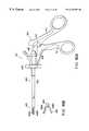
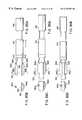
- FIGS. 1A, 1 B, and 2show the first embodiment of the present invention.
- a bipolar forceps 1 as a high-frequency treatment tool of this embodimentcomprises a long insertion portion 2 to be inserted into the body cavity of a patient, a treatment portion 3 attached to the distal end portion of the insertion portion 2 to grip vital tissue and coagulate or incise it, and an operation portion 4 coupled to the proximal end portion of the insertion portion 2 .
- a high-frequency currentis supplied to the treatment portion 3 through a conductive member (not shown), so vital tissue gripped by the treatment portion 3 is coagulated or incised.
- the insertion portion 2has a rotatable sheath 5 .
- a rod 7 movable back and forthis arranged in the sheath 5 .
- a pair of jaws 8 a and 8 b forming the treatment portion 3are coupled to the distal end of the rod 7 through a link mechanism 10 .
- These jaws 8 a and 8 bfunction as gripping members for gripping tissue and electrodes for flowing a high-frequency current to the gripped tissue.
- the link mechanism 10has a pair of links 21 and 22 pivotally coupled to the distal end of the rod 7 through a pivot pin 29 .
- the first link 21is pivotally coupled to the proximal end portion of one jaw 8 b through a pivot pin 23 .
- the second link 22is pivotally coupled to the proximal end portion of the other jaw 8 a through a pivot pin 24 .
- the pair of jaws 8 a and 8 bare pivotally coupled to each other through a pin 25 supported by a pair of arms 20 extending from both sides of the distal end portion of the sheath 5 .
- the link mechanism 10operates to pivot the jaws 8 a and 8 b about the pin 25 (the treatment portion 3 is opened/closed).
- serrate portions 26 meshing each other upon closing the treatment portion 3are formed on the inner gripping surfaces of the jaws 8 a and 8 b.
- the distal end portions of the jaws 8 a and 8 bare formed as insulating portions 12 .
- the insulating portions 12may be formed by forming the entire distal end portions of the jaws 8 a and 8 b from a material having electrical insulating properties.
- the insulating portions 12may be made entirely of material having electrical insulating properties wherein the thickness of the insulating portions at at least one point is equal to a thickness of the corresponding jaw 8 a , 8 b .
- the insulating portions 12may be formed by insulating coating on the outer surfaces of the distal end portions of the jaws 8 a and 8 b .
- a ceramic having the highest heat resistance and free from degradation in electrical insulating propertiesis preferably used.
- a predetermined gap Cis formed between the gripping surfaces (serrate portions 26 ) of the jaws 8 a and 8 b except the insulating portions 12 . That is, when tissue is gripped, the conductive portions of the jaws 8 a and 8 b to which a high-frequency current is supplied do not come into contact with each other (no electrical short circuit occurs between the jaws 8 a and 8 b ).
- the conductive member electrically connected to the jaws 8 a and 8 bextends through the sheath 5 and is connected to a connector receptacle 13 of the operation portion 4 .
- a cable 14 extending from a high-frequency cautery power supply unit 15is connected to the connector receptacle 13 .
- the high-frequency cautery power supply unit 15has a foot switch 16 for turning on/off the power supply unit 15 .
- the operation portion 4has a grip 6 which can be gripped with a hand.
- the grip 6has a finger hook portion 6 a on which the operator places the thumb and a finger hook portion 6 b on which the operator places the middle finger.
- the grip 6also has a trigger 17 as a forceps operation means. This trigger 17 is pivotally coupled to the upper end portion of the grip 6 through a pivot pin 18 .
- the trigger 17is coupled to the proximal end portion of the rod 7 .
- the trigger 17has finger hook portions 17 a on which the operator places the index finger.
- the cable 14is connected to the connector receptacle 13 of the bipolar forceps 1 to electrically connect the bipolar forceps 1 to the high-frequency cautery power supply unit 15 .
- the trigger 17 of the operation portion 4is pivoted in a direction indicated by an arrow a to move the rod 7 backward to the hand side and close the jaws 8 a and 8 b (treatment portion 3 ) through the link mechanism 10 .
- the insertion portion 2 of the bipolar forceps 1is inserted into the body of a patient, and the treatment portion 3 at the distal end of the insertion portion 2 is moved close to the tissue to be treated in the body.
- the trigger 17When the treatment portion 3 is positioned near the tissue to be treated, the trigger 17 is pivoted in a direction indicated by an arrow b to move the rod 7 forward and open the jaws 8 a and 8 b (treatment portion 3 ) through the link mechanism 10 (FIG. 1 B).
- the vital tissueis inserted between the opened jaws 8 a and 8 b .
- the trigger 17When the trigger 17 is operated to close the jaws 8 a and 8 b again, the vital tissue is gripped by the jaws 8 a and 8 b . Even when the vital tissue is membranous tissue, the conductive portions of the jaws 8 a and 8 b to which the high-frequency current is supplied do not come into contact with each other (no electrical short circuit occurs between the jaws 8 a and 8 b ).
- the insulating portions 12 of the jaws 8 a and 8 bmesh and contact each other, and the predetermined gap C is formed between the gripping surfaces (serrate portions 26 ) of the jaws 8 a and 8 b except the insulating portions 12 . That is, when tissue is gripped, the conductive portions of the jaws 8 a and 8 b to which a high-frequency current is supplied do not come into contact with each other. Hence, when tissue is gripped by the jaws 8 a and 8 b , no electrical short circuit occurs between the jaws 8 a and 8 b .
- Jpn. Pat. Appln, KOKAI Publication No. 8-317936discloses an arrangement in which a U-shaped insulating member is arranged on the gripping surface of a jaw. This insulating member aims at applying a pressure to the gripped tissue for proper coagulation and cannot prevent an electrical short circuit between the jaws.
- the insulating portions 12are formed only at the distal end portions of the jaws 8 a and 8 b . Hence, the tissue coagulation range can be increased without any short circuit between the conductive portions (the conductive tissue area can be increased).
- the insulating portions 12are formed on the jaws 8 a and 8 b .
- the insulating portionmay be formed on only one jaw 8 a ( 8 b ). It is only necessary that at least one of portions of the jaws 8 a and 8 b which come into contact with each other upon closing the treatment portion 3 is formed as the insulating portion 12 .
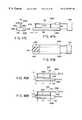
- FIG. 3shows the second embodiment of the present invention.
- a high-frequency treatment tool of this embodimenthas the same arrangement as that of the first embodiment except the shape of serrate portions 26 formed on the gripping surfaces of jaws 8 a and 8 b . Hence, the same function and effect as in the first embodiment can be obtained.
- FIGS. 4A and 4Bshow the third embodiment of the present invention.
- the conductive path of a high-frequency current to jaws 8 a and 8 bis formed by a rod 7 and links 21 and 22 in the arrangement of the first embodiment. More specifically, the pair of links 21 and 22 are pivotally coupled to the distal end of the rod 7 through a pivot pin 29 .
- the first link 21is pivotally coupled to the proximal end portion of one jaw 8 b through a pivot pin 23 .
- the second link 22is pivotally coupled to the proximal end portion of the other jaw 8 a through a pivot pin 24 .
- the pair of jaws 8 a and 8 bare pivotally coupled to each other through a pin 25 supported by a pair of arms 20 extending from both sides of the distal end portion of a sheath 5 .
- the rod 7has two conductive regions 7 a and 7 b electrically insulated from each other by an insulating member 7 c .
- the conductive region 7 ais electrically connected to one jaw 8 a through the second link 22 .
- the conductive region 7 bis electrically connected to the other jaw 8 b through the first link 21 .
- the pivot pins 24 , 25 , and 29are covered with insulating tubes.
- the remaining portions including insulating portions 12have the same arrangement as in the first embodiment.
- the same function and effect as in the first embodimentcan be obtained. Additionally, the conductive paths to the jaws 8 a and 8 b can be simplified.
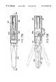
- FIGS. 5A to 5 Cshow the fourth embodiment of the present invention.
- a bipolar forceps as a high-frequency treatment tool of this embodimentcomprises a long insertion portion 2 to be inserted into the body cavity of a patient, a treatment portion 3 attached to the distal end portion of the insertion portion 2 to grip vital tissue and coagulate or incise it, and an operation portion (not shown) coupled to the proximal end portion of the insertion portion 2 .
- the operation portion of this embodimenthas the same arrangement as that of the operation portion 4 of the first embodiment.
- the same reference numerals as in the first embodimentdenote the same parts in the fourth embodiment, and a detailed description thereof will be omitted.
- the insertion portion 2is comprised of a rotatable outer sheath 39 and an inner sheath 30 inserted in the outer sheath 39 to move back and forth.
- the inner sheath 30is inserted into a grip 6 of the operation portion.
- the proximal end portion of the inner sheath 30is coupled to a trigger 17 .
- a cap 33 having electrical insulating propertiesis connected and fixed to the distal end portion of the inner sheath 30 .
- a gripping member 31 having electrical insulating propertiesis fitted in the inner sheath 30 .
- a pair of elastic members 32 a and 32 bare stationarily held by the holding member 31 .
- the elastic members 32 a and 32 bare comprised of conductive rods 35 formed from a spring steel or the like. Each conductive rod 35 is covered with an insulating tube 36 .
- the proximal end portions of the conductive rods 35 of the elastic members 32 a and 32 bare connected to a connector receptacle 13 of an operation portion 4 .
- the elastic members 32 a and 32 bhave jaws 8 a and 8 b at their distal ends, respectively, and always bias the jaws 8 a and 8 b in the opening direction.
- the distal end portion of one jaw 8 ais formed as an insulating portion 12 .
- the insulating portion 12may be formed by forming the entire distal end portion of the jaw 8 a from a material having electrical insulating properties. Alternatively, the insulating portion 12 may be formed by insulating coating of the outer surface of the distal end portion of the jaw 8 a . In this embodiment, in the state shown in FIG.
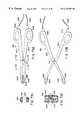
- FIGS. 6A to 6 Dshow the fifth embodiment of the present invention.
- a high-frequency treatment tool of this embodimentis a ventromy forceps 40 in the form of scissors and has a pair of forceps members 41 a and 41 b with the same shape.
- the forceps members 41 a and 41 bare formed from conductive members and are pivotally coupled to each other through a pivot shaft 42 at almost middle portions.
- the proximal end portions of the forceps members 41 a and 41 bare formed as finger hook portions 44 a and 44 b , respectively.
- Cables 45 a and 45 b connected to a high-frequency cautery power supply unit(not shown) are connected to the finger hook portions 44 a and 44 b , respectively.
- the forceps members 41 a and 41 bhave jaws 42 a and 42 b at their distal end portions, respectively.
- serrate portions 26 meshing each other upon closing the jaws 42 a and 42 bare formed on the inner gripping surfaces of the jaws 42 a and 42 b.
- the pair of forceps members 41 a and 41 b and pivot shaft 42are covered with insulating members 46 . Only the serrate portions 26 formed on the jaws 42 a and 42 b are exposed from the insulating members 46 to form electrode portions. Bent portions 43 bent inward are formed at the distal end portions of the jaws 42 a and 42 b.
- the vital tissuewhen vital tissue is gripped between the serrate portions 26 of the jaws 42 a and 42 b , and a coagulation current or incision current is flowed to the serrate portions 26 through the conductive portions of the forceps members 41 a and 41 b , the vital tissue can be coagulated or incised.
- the ventromy forceps 40 of this embodimentwhen the jaws 42 a and 42 b are completely closed, only the bent portions (insulating portions) 43 of the jaws 42 a and 42 b mesh and contact each other, and the predetermined gap C is formed between the gripping surfaces (serrate portions 26 ) of the jaws 42 a and 42 b except the bent portions 43 .
- the jaws 42 a and 42 bwhen tissue is gripped by the jaws 42 a and 42 b , no electrical short circuit occurs between the jaws 42 a and 42 b . For this reason, even thin membranous tissue can be reliably coagulated or incised.
- FIGS. 7A to 9 Cshow the sixth embodiment of the present invention.
- a high-frequency treatment tool of this embodimenthas a pair of gripping members 50 and 51 for gripping vital tissue to coagulate or incise it.
- the gripping members 50 and 51are opened/closed by, e.g., the same mechanism as in the fourth embodiment shown in FIGS. 5A to 5 C.
- the insertion and operation portions for supporting the gripping members 50 and 51also have the same arrangement as in the fourth embodiment.
- the same reference numerals as in the fourth embodimentdenote the same parts in the sixth embodiment, and a detailed description thereof will be omitted.
- one gripping member 51is formed as a first electrode portion consisting of a conductive material.
- the first electrode portion 51has a through hole 52 extending in the longitudinal direction and therefore has an almost loop shape.
- the other gripping member 50has two electrode portions 53 and 54 electrically insulated from each other by an insulating member 55 .
- the insulating member 55has a shape almost conforming to the first electrode portion 51 and comes into contact with the first electrode portion 51 when the gripping members 50 and 51 are closed, as shown in FIG. 8 B.
- the second electrode portion 53 outside the insulating member 55functions as a coagulation electrode.
- the electrode portion 53extends in an almost U shape along the insulating member 55 and is also positioned on both sides of the first electrode portion 51 to surround it when the gripping members 50 and 51 are closed as shown in FIG. 8 B.
- the third electrode portion 54 inside the insulating member 55functions as an incision electrode.
- the electrode portion 54projects in a chevron shape from the gripping surface of the insulating member 55 and also enter the through hole 52 of the first electrode portion 51 when the gripping members 50 and 51 are closed, as shown in FIG. 8 B.
- the electrode portions 51 , 53 , and 54are connected to a connector receptacle 13 of an operation portion 4 through conductive rods 35 of elastic members 32 a and 32 b , so a high-frequency current is supplied from a high-frequency cautery power supply unit 15 through a cable 14 .
- FIGS. 9A to 9 Cshow steps of coagulating/incising vital tissue P using the gripping members 50 and 51 having the above arrangement.
- FIG. 9Ashows a state wherein the gripping members 50 and 51 are opened to position the vital tissue P between the gripping members 50 and 51 , and then, the gripping members 50 and 51 are closed to sandwich the vital tissue P between the gripping members 50 and 51 .
- the electrode portions 51 and 53 or electrode portions 51 and 54 to which a high-frequency current is supplieddo not come into contact. This is because when the gripping members 50 and 51 are completely closed, the first electrode portion 51 comes into contact with only the insulating member 55 . In this state, a coagulation current is flowed across the second electrode portion 53 as the coagulation electrode and the first electrode portion 51 to coagulate the vital tissue P.
- the gripping members 50 and 51are slightly opened, as shown in FIG. 9B, to switch the power to an incision current.
- the gripping members 50 and 51are closed again, and the incision current is flowed across the third electrode portion 54 as the incision electrode and the first electrode portion 51 to incise the vital tissue P, as shown in FIG. 9 C.
- the first electrode portion 51comes into contact with only the insulating member 55 . That is, when tissue is gripped by the gripping members 50 and 51 , the electrode portions 51 and 53 or electrode portions 51 and 54 to which a high-frequency current is supplied do not come into contact with each other. Hence, no electrical short circuit occurs between the gripping members 50 and 51 , and even thin membranous tissue can be reliably coagulated or incised.
- the electrode portionsdo not short-circuit. For this reason, proper coagulation or incision can be performed.
- the operation force of the trigger 17need not be finely adjusted, the operability is good.
- an insulating member 55is inserted between the electrode portions 53 and 54 of the gripping member 50 , so the tissue can also be gripped by the insulating portion 55 . Hence, the operator can reliably grip and coagulate/incise the tissue without missing it.
- a distal end region 55 a of the gripping surface of the insulating member 55may be formed at a higher level than that of the remaining regions instead of forming the entire gripping surface of the insulating member 55 at the uniform level.
- FIGS. 10 to 12 Bshow the seventh embodiment of the present invention.
- a bipolar forceps 60 as a high-frequency treatment tool of this embodimentcomprises a sheath 61 as an insertion portion to be inserted into the body cavity of a patient, a treatment portion 62 attached to the distal end portion of the sheath 61 to grip vital tissue and coagulate or incise it, and an operation portion 63 coupled to the proximal end portion of the sheath 61 .
- the sheath 61is rotated by operating a rotary operation portion 64 on the operation portion 63 side.
- the treatment portion 62has a pair of jaws 71 and 72 which can be opened/closed.
- the operation portion 63has a fixed handle 65 and a movable handle 66 .
- the jaws 71 and 72are opened/closed by pivoting the movable handle 66 .
- a conductive member serving as a path for supplying a high-frequency currentis electrically connected to the jaws 71 and 72 .
- This conductive memberextends through the sheath 61 and is connected to a connector receptacle 67 of the operation portion 63 .
- a cable 68 extending from a high-frequency cautery power supply unit 69is connected to the connector receptacle 67 .
- the high-frequency cautery power supply unit 69has a foot switch 70 for turning on/off the power supply unit 69 .
- the foot switch 70has an incision switch portion and a coagulation switch portion.
- the first jaw 71 on one side of the treatment portion 62comprises a main body portion 74 formed from a conductive material and having a U-shaped section. Serrate gripping portions 74 a are formed on both sides of the main body portion 74 .
- an insulating member 73 for gripping tissue together with the gripping portions 74 ais fixed between the gripping portions 74 a .
- This insulating member 73is substantially arranged throughout the total length of the main body portion 74 .
- the second jaw 72 on the other side of the treatment portion 62has formed as a rod consisting of a conductive material and having a circular section. The second jaw 72 is located to come into contact with only the insulating member 73 when the treatment portion 62 is closed.
- FIGS. 12A and 12Bshow steps of coagulating/incising tissue P using the bipolar forceps 60 having the above arrangement.
- FIG. 12Ashows a state wherein the tissue P is sandwiched by the gripping portions 74 a of the first jaw 71 and second jaw 72 . Even when the tissue P is membranous one, the jaws 71 and 72 to which a high-frequency current is supplied do not come into contact. This is because when the treatment portion 62 is completely closed, the second jaw 72 comes into contact with only the insulating member 73 . In this state, a coagulation current is flowed across the jaws 72 and 72 to coagulate the tissue P.
- the treatment portion 62Upon completing coagulation, the treatment portion 62 is more tightly closed to sandwich the tissue P by the gripping portions 74 a of the first jaw 71 , insulating member 73 , and second jaw 72 . At this time as well, the jaws 71 and 72 do not come into contact with each other. In this state, an incision current is flowed across the jaws 71 and 72 to incise the tissue P.
- the second jaw 72comes into contact with only the insulating member 73 of the first jaw 71 . That is, when tissue is gripped by the jaws 71 and 72 , the electrode portions to which a high-frequency current is supplied do not come into contact with each other. Hence, no electrical short circuit occurs between the jaws 71 and 72 , and even thin membranous tissue can be reliably coagulated or incised.
- the insulating member 73is sandwiched by the gripping portions 74 a of the first jaw 71 , and the tissue is also gripped by this insulating member 73 .
- the operatorcan reliably grip the tissue without missing it and coagulate/incise it (This also applies to the sixth embodiment.
- an insulating member commonly used as a gripping means and a short circuit prevention meansis very effective.
- a high-frequency treatment tool disclosed in DE 4032471 C2grips tissue by three rod electrodes. For this reason, the tissue is missed upon gripping and cannot be reliably gripped, and coagulation or incision cannot be reliably performed.
- FIGS. 13A and 13Bshow the eighth embodiment of the present invention.
- the arrangement of a second jaw 72is different from that in the seventh embodiment. More specifically, in this embodiment, the second jaw 72 comprises a main body portion 76 consisting of a material having electrical insulating properties and an electrode portion 77 consisting of a conductive material and arranged almost at the central portion of the main body portion 76 to substantially extend along the total length of the main body portion 76 . Serrate gripping portions 76 a meshing with gripping portions 74 a of a first jaw 71 are formed on both sides of the main body portion 76 . The arrangement of the remaining portions is the same as in the seventh embodiment.
- the tissue gripping areaincreases as compared to the seventh embodiment, so tissue can be reliably gripped.
- FIGS. 14 to 16 Bshow the ninth embodiment of the present invention.
- a bipolar forceps as a high-frequency treatment tool of this embodimenthas a treatment portion comprising a first jaw 80 and a second jaw 81 .
- the first jaw 80has two coagulation electrode portions 83 and 84 electrically insulated from each other by an insulating member 82 .
- the first coagulation electrode portion 83 and second coagulation electrode portion 84are positioned on both sides of the insulating member 82 to sandwich the insulating member 82 .
- the distal ends of the electrode portions 83 and 84are formed as serrate gripping portions 83 a and 84 a , respectively.
- the second jaw 81comprises a rod consisting of a conductive material and having a circular section and is formed as an incision electrode portion.
- the second jaw (electrode portion) 81is located to come into contact with only the insulating member 82 when the treatment portion is kept closed.
- a high-frequency cautery power supply unit 69 for supplying a high-frequency current to the electrode portions 81 , 83 , and 84has an arrangement shown in FIG. 15 .
- reference numeral 85denotes an output circuit for supplying a high-frequency current
- 86a control circuit for controlling the high-frequency output from the output circuit 85 in accordance with a control signal from a foot switch 70
- 88a setting means for inputting a predetermined output condition to the control circuit 86 as an electrical signal
- 92a connector to which a power supply cable from the bipolar forceps is connected
- 89 , 90 , and 91lines for connecting the output circuit 85 to the connector 92 in correspondence with the electrode portions 81 , 83 , and 84 , respectively
- 87a detection circuit for detecting the high-frequency current flowing through the lines 89 , 90 , and 91 and sending a detection signal to the line 89 .
- the arrangement of the remaining portionsis
- FIGS. 16A and 16Bshow steps of coagulating/incising tissue P using the bipolar forceps having the above arrangement.
- FIG. 16Ashows a state wherein the tissue P is sandwiched by the first jaw 80 and second jaw 81 . Even when the tissue P has a thin film shape, the jaws 80 and 81 to which a high-frequency current is supplied do not come into contact with each other. This is because when the treatment portion is completely closed, the second jaw 81 comes into contact with only the insulating member 82 . In this state, a coagulation current is flowed across the two coagulation electrode portions 83 and 84 of the first jaw 80 to coagulate the tissue P.
- the treatment portionUpon completing coagulation, the treatment portion is further tightly closed, and the tissue P is pressed against the insulating member 82 by the second jaw 81 . In this case as well, the jaws 80 and 81 do not come into contact with each other. In this state, an incision current is flowed across the first coagulation electrode portion 83 and the incision electrode portion (second jaw) 81 and across the second coagulation electrode portion 84 and the incision electrode portion (second jaw) 81 to incise the tissue P.
- the second jaw 81comes into contact with only the insulating member 82 of the first jaw 80 . That is, when the tissue is gripped by the jaws 80 and 81 , the electrode portions to which a high-frequency current is supplied do not come into contact with each other. Hence, no electrical short circuit occurs between the jaws 8 a and 8 b , and even thin membranous tissue can be reliably coagulated or incised.
- the insulating member 82is sandwiched by the two electrode portions 83 and 84 of the first jaw 80 , and the tissue is also gripped by this insulating member 82 . Hence, the operator can reliably grip the tissue without missing it and coagulate/incise it.
- the three lines 89 , 90 , and 91 corresponding to the electrode portions 81 , 83 , and 84 , respectively,are arranged in the high-frequency cautery power supply unit 69 .
- the switch for switching between incision and coagulationneed not be provided on the operation portion side of the bipolar forceps.
- the coagulation rangecan be increased as compared to the seventh and eighth embodiments.
- FIG. 17shows the 10th embodiment of the present invention.
- the arrangement of a second jaw 81is different from that in the ninth embodiment. More specifically, the second jaw 81 comprises a main body portion 95 consisting of a material having electrical insulating properties, and an electrode portion 96 consisting of a conductive material and arranged almost at the central portion of the main body portion 95 to substantially extend throughout the total length of the main body portion 95 . Serrate gripping portions 95 a meshing with gripping portions 83 a and 84 a of a first jaw 80 are formed on both sides of the main body portion 95 . The arrangement of the remaining portions is the same as in the ninth embodiment.
- the tissue gripping areaincreases as compared to the ninth embodiment, so tissue can be reliably gripped.
- FIGS. 18A and 18Bshow the 11th embodiment of the present invention.
- a high-frequency treatment tool of this embodimentcomprises a long insertion portion 2 to be inserted into the body cavity of a patient, a treatment portion 3 attached to the distal end portion of the insertion portion 2 to grip vital tissue and coagulate or incise it, and an operation portion 4 coupled to the proximal end portion of the insertion portion 2 .
- the insertion portion 2has a sheath 106 rotatably supported by a rotary operation portion 105 of the operation portion 4 .
- a driving shaft 107 extending into the operation portion 4is inserted into the sheath 106 to freely move back and forth.
- First and second jaws 8 a and 8 b as electrodes constituting the treatment portion 3are fixed at the distal end portion of the driving shaft 107 while being biased in the opening direction.
- the operation portion 4has a fixed handle 111 integrated with an operation portion main body 109 and a movable handle 113 attached to the operation portion main body 109 through a pivot pin 112 as a fulcrum to freely pivot.
- the proximal end portion of the driving shaft 107is fixed to the movable handle 113 .
- a projecting portion 120is formed on a surface of the fixed handle 111 opposing the movable handle 113 .
- the movable handle 113has an abutment portion 121 which can abut against the projecting portion 120 when the movable handle 113 is pivoted to the fixed handle 111 side.
- the driving shaft 107is pulled back by the movable handle 113 , so the proximal sides of the first and second jaws 8 a and 8 b are accommodated in the sheath 106 .
- the first and second jaws 8 a and 8 b biased in the opening directionare forcibly pressed by the inner wall of the sheath 106 in a direction in which the jaws 8 a and 8 b are close to each other to start to close the treatment portion 3 .
- the treatment portion 3is not closed anymore, and a predetermined gap C is formed between the first jaw 8 a and second jaw 8 b . That is, when tissue is gripped, the conductive portions of the jaws 8 a and 8 b to which a high-frequency current is supplied do not come into contact with each other. Hence, when tissue is gripped by the jaws 8 a and 8 b , no electrical short circuit occurs between the jaws 8 a and 8 b . For this reason, even thin membranous tissue can be reliably coagulated or incised.
- FIGS. 19 to 25show the 12th embodiment of the present invention.
- a bipolar forceps 201 as a high-frequency treatment tool of this embodimentcomprises a sheath 202 as an insertion portion 2 to be inserted into the body cavity of a patient, a treatment portion 203 attached to the distal end portion of the sheath 202 to grip vital tissue and coagulate or incise it, and an operation portion 204 coupled to the proximal end portion of the sheath 202 .
- the sheath 202is rotated by operating a rotary operation portion 205 provided on the operation portion 204 side.
- the treatment portion 203has a pair of jaws 206 and 207 which can be opened/closed.
- the operation portion 204comprises a fixed handle 208 and a movable handle 209 . When the movable handle 209 is pivoted, the jaws 206 and 207 are opened/closed.
- a conductive member as a high-frequency current supply pathis electrically connected to the jaws 206 and 207 (more accurately, electrode portions to be described later). This conductive member extends through the sheath 202 and is connected to a connector receptacle 211 of the operation portion 204 .
- a cable 212 extending from a high-frequency cautery power supply unit 213is connected to the connector receptacle 211 .
- the high-frequency cautery power supply unit 213has a foot switch 214 for turning on/off the power supply unit 213 .
- the foot switch 214has an incision switch portion and a coagulation switch portion.
- the operation portion 204has a change-over switch 210 for switching the high-frequency current to be supplied to the jaws 206 and 207 between incision and coagulation (switching between the incision current and the coagulation current).
- the first jaw 206 on one side of the treatment portion 203has two electrode portions 220 and 222 electrically insulated from each other by an insulating member 221 . More specifically, the insulating member 221 is arranged on both sides of the first electrode portion 220 . The second electrode portion 222 sandwiches the insulating member 221 from both sides. That is, the first jaw 206 has a structure in which the electrode portions 220 and 222 and insulating member 221 are sequentially stacked in the direction of width.
- the first electrode portion 220 inside the insulating member 221functions as an incision electrode and projects in a chevron shape from the gripping surface of the insulating member 221 .
- the second electrode portion 222 located outside the insulating member 221functions as a coagulation electrode.
- the second jaw 207 on the other side of the treatment portion 203is formed as a third electrode portion consisting of a conductive material.
- the third electrode portion 207has a flat gripping portion opposing the first and second electrode portions 220 and 222 and insulating member 221 .
- the high-frequency cautery power supply unit 213 for supplying a high-frequency current to the electrode portions 207 , 220 , and 222has an arrangement shown in FIG. 25 .
- reference numeral 213 bdenotes an output circuit for supplying a high-frequency current
- 213 aa control circuit for controlling the high-frequency output from the output circuit 213 b in accordance with a control signal from the foot switch 214
- 213 ca setting means for inputting a predetermined output condition to the control circuit 213 a as an electrical signal
- 213 dan output connector connected to an electrical cable extending from the bipolar forceps
- 213 ea high-frequency output line connecting the output circuit 213 b to the output connector 213 d
- 213 fa detection circuit for detecting the impedance of tissue from the high-frequency current flowing through the line 213 e and sending a detection signal to the control circuit 213 a.
- FIGS. 21A and 21Bshow steps of coagulating/incising vital tissue P using the jaws 206 and 207 having the above arrangement.
- FIG. 21Ashows a state wherein the jaws 206 and 207 are closed to sandwich the vital tissue P between the jaws 206 and 207 .
- the tissue Pis gripped not only by the electrode portions 207 , 220 , and 222 but also by the insulating member 221 . That is, the insulating member 221 between the electrode portions 220 and 222 prevents the tissue gripped by the electrode portions 207 , 220 , and 222 from escape.
- a second coagulation currentis flowed across the second electrode portion 222 as a coagulation current and the third electrode portion 207 to coagulate the vial tissue P.
- the coagulation currentis supplied from the output circuit 213 b and has load characteristics representing that when the impedance of the vital tissue P increases upon coagulation, the output decreases, as shown in FIG. 22 .
- the impedance of the vital tissue Pchanges over time, as shown in FIG. 24 .
- This change in impedance of the vital tissue Pis detected by the control circuit 213 a through the detection circuit 213 f .
- the control circuit 213 astops outputting the coagulation current from the output circuit 213 b.
- coagulationoutput of the coagulation current
- the foot switch 214More specifically, an automatic mode in which coagulation is automatically stopped by the control circuit 213 a and a manual mode in which output of the coagulation current is stopped not by the control circuit 213 a but on the basis of operator's judgment can be selected by the setting means 213 c .
- the manual modeis selected by the setting means 213 c , the operator is warned of the end of coagulation by a buzzer sound or the like at the time point when coagulation is completely performed (at the point X on the impedance curve shown in FIG. 24 ).
- the control circuit 213 apreferably allows incision output by the incision output operation of the foot switch 214 only after the coagulation output is performed by the coagulation output operation of the foot switch 214 .
- FIG. 21Bshows the contact area between the electrode portion 220 and the tissue.
- the insulating member 221is inserted between the electrode portions 220 and 222 of the first jaw 206 , so the tissue can also be gripped by the insulating member 221 . Hence, the operator can reliably grip tissue without missing it and coagulate/incise it.
- the coagulation current outputis automatically stopped by the control circuit 213 a at a time point when the vital tissue P is completely coagulated.
- the manual modethe operator is warned of the end of coagulation by a buzzer sound or the like at a time point when coagulation is complete. That is, incision can be performed after the tissue is gripped and reliably coagulated. Hence, neither faulty coagulation nor bleeding during incision occurs.
- a conventional bipolar forcepssinissors forceps
- incisioncan be performed by the operator's intention even when coagulation is incomplete, so bleeding may take place during incision.
- an electrical insulating portionmay be formed on the gripping surface of at least one gripping portion (jaw 206 or 207 ), as in the first to fifth embodiments.
- a predetermined gapis formed between the gripping surfaces of the gripping portions when the gripping portions are completely closed to make the electrical insulating portion abut against the gripping surface of the other gripping portion, thereby preventing a short circuit between the electrode portions of the gripping portions.
- an electrical insulating portionmay be formed on the gripping surface of one gripping portion (jaw 206 or 207 ).
- an abutment portion 121may be formed on the movable handle 209 , and a projecting portion 120 may be formed on the fixed handle 208 .
- the projecting portion 120abuts against the abutment portion 121 , the treatment portion 203 is not closed anymore, and a predetermined gap C is formed between the first jaw 206 and the second jaw 207 .
- FIG. 26shows a modification of the 12th embodiment.
- serrate gripping portions 222 aare formed almost across the total length of the first jaw 206 in the longitudinal direction.
- the gripping portions 222 aare formed on the electrode portion 222 as a coagulation electrode.
- serrate gripping portions 207 a meshing with the gripping portions 222 aare formed almost across the total length of the second jaw 207 in the longitudinal direction.
- the arrangement of the remaining portionsis the same as in the 12th embodiment.
- FIGS. 27 to 30 Bshow the 13th embodiment of the present invention.
- the same reference numerals as in the 12th embodimentdenote the same parts in the 13th embodiment, and a detailed description thereof will be omitted.
- a bipolar forceps 201 A as a high-frequency treatment tool of this embodimentcomprises a sheath 202 , a treatment portion 203 , and an operation portion 204 .
- the treatment portion 203comprises a pair of jaws 225 and 226 which can be opened/closed.
- the first jaw 225 on one side of the treatment portion 203has two electrode portions 228 and 229 electrically insulated from each other by an insulating member 227 . More specifically, the insulating member 227 is arranged on the upper surface of the first electrode portion 228 , and the second electrode portion 229 wider than the insulating member 227 and first electrode portion 228 is arranged on the upper surface of the insulating member 227 . That is, the first jaw 225 has a structure in which the electrode portions 228 and 229 and insulating member 227 are sequentially stacked in the direction of height.
- the first electrode portion 228 on the lower side of the insulating member 227functions as an incision electrode and is tapered downward together with the insulating member 227 .
- the second electrode portion 229 on the upper side of the insulating member 227functions as a coagulation electrode.
- the second jaw 226 on the other side of the treatment portion 203is formed as a third electrode portion consisting of a conductive material.
- a V-shaped mesh groove 226 a which can engage with the insulating member 227 and first electrode portion 228is formed in the gripping surface of the third electrode portion 226 in the longitudinal direction of the electrode portion 226 .
- a high-frequency cautery power supply unit 213 A for supplying a high-frequency current to the electrode portions 226 , 228 , and 229has an arrangement shown in FIG. 28 .
- reference numeral 213 bdenotes an output circuit for supplying a high-frequency current
- 213 aa control circuit for controlling the high-frequency output from the output circuit 213 b in accordance with a control signal from a foot switch 214
- 213 ca setting means for inputting a predetermined output condition to the control circuit 213 a as an electrical signal
- 213 dan output connector connected to an electrical cable extending from the bipolar forceps 201 A
- 213 g , 213 h , and 213 ilines connecting the output circuit 213 b to the output connector 213 d and electrically connected to the electrode portions 226 , 228 , and 229 , respectively
- 213 fa detection circuit for detecting the impedance of tissue
- FIGS. 30A and 30Bshow steps of coagulating/incising vital tissue P using the jaws 225 and 226 having the above arrangement.
- FIG. 30Ashows a state wherein the jaws 225 and 226 are closed to sandwich the vital tissue P between the jaws 225 and 226 .
- the tissue Pis gripped not only by the electrode portions 226 , 228 , and 229 but also by the insulating member 227 .
- the insulating member 227 and first electrode portion 228move to mesh with the groove 226 a of the third electrode portion 226 , and the tissue P is sandwiched by the electrode portions 226 , 228 , and 229 and insulating member 227 to be pressed into the groove 226 a and reliably gripped.
- a coagulation currentis flowed across the second electrode portion 229 and the third electrode portion 226 to coagulate the vital tissue P.
- a change in impedance of the tissue Pis detected by the control circuit 213 a through the detection circuit 213 f , as in the 12th embodiment.
- the control circuit 213 astops outputting the coagulation current from the output circuit 213 b .
- a manual modeis selected by the setting means 213 c , the operator is warned of the end of coagulation by a buzzer sound or the like at the time point when coagulation is completely performed (at the point X on the impedance curve shown in FIG. 24 ).
- an incision currentis flowed across the first electrode portion 228 as an incision electrode and the third electrode portion 226 , as shown in FIG. 30B, to incise the vital tissue P.
- the insulating member 227is inserted between the electrode portions 228 and 229 of the first jaw 225 , so the tissue can also be gripped by the insulating member 227 . Hence, the operator can reliably grip and coagulate/incise the tissue without missing it.
- the coagulation current outputis automatically stopped by the control circuit 213 a at a time point when the vital tissue P is completely coagulated.
- the operatoris warned of the end of coagulation by a buzzer sound or the like at a time point when coagulation is complete. That is, incision can be performed after the tissue is gripped and reliably coagulated. Hence, neither faulty coagulation nor bleeding during incision occurs.
- an electrical insulating portionmay be formed on the gripping surface of at least one gripping portion (jaw 225 or 226 ), as in the first to fifth embodiments.
- a predetermined gapis formed between the gripping surfaces of the gripping portions when the gripping portions are completely closed to make the electrical insulating portion abut against the gripping surface of the other gripping portion, thereby preventing a short circuit between the electrode portions of the gripping portions.
- an electrical insulating portionmay be formed on the gripping surface of one gripping portion (jaw 225 or 226 ).
- an abutment portion 121may be formed on a movable handle 209
- a projecting portion 120may be formed on a fixed handle 208 .
- FIGS. 31A to 34 Bshow the 14th embodiment of the present invention.
- a bipolar forceps 230 as a high-frequency treatment tool of this embodimentcomprises a long insertion portion 232 to be inserted into the body cavity of a patient, a treatment portion 233 attached to the distal end portion of the insertion portion 232 to grip vital tissue and coagulate or incise it, and an operation portion 234 coupled to the proximal end portion of the insertion portion 232 .
- the operation portion 234has a grip 236 which can be gripped with a hand.
- the grip 236has a finger hook portion 236 a on which the operator places the thumb.
- the grip 236also has a trigger 247 as a forceps operation means. This trigger 247 is pivotally coupled to the upper end portion of the grip 236 through a pivot pin 248 .
- the trigger 247has finger hook portions 247 a and 247 b on which the operator places the index and middle fingers, respectively.
- the operation portion 234has a connector receptacle 243 .
- a cable 244 extending from a high-frequency cautery power supply unit 245is connected to the connector receptacle 243 .
- the high-frequency cautery power supply unit 245has a foot switch 246 for turning on/off the power supply unit 245 .
- the insertion portion 232is comprised of a rotatable outer sheath 235 and an inner sheath 237 inserted in the outer sheath 235 to move back and forth.
- the inner sheath 237is inserted into the grip 236 of the operation portion 234 .
- the proximal end portion of the inner sheath 237is coupled to the trigger 247 .
- a holding member having electrical insulating propertiesis fitted in the inner sheath 237 .
- a pair of elastic members 239 a and 239 bare stationarily held by the holding member.
- the elastic members 239 a and 239 bare comprised of conductive rods formed from a spring steel or the like. Each conductive rod is covered with an insulating tube.
- the proximal end portions of the conductive rods of the elastic members 239 a and 239 bare connected to the connector receptacle 243 of the operation portion 234 , and the distal end portions project from the distal end of the inner sheath 237 .
- the elastic members 239 a and 239 bhave jaws 238 a and 238 b forming the treatment portion 233 at their distal ends, respectively, and always bias the jaws 238 a and 238 b in the opening direction.
- the elastic members 239 a and 239 brelatively project from the inner sheath 237 , so the jaws 238 a and 238 b are opened by the restoring force of the elastic members 239 a and 239 b (FIG. 31 B).
- the second jaw 238 b at the distal end of the elastic member 239 bis formed as the first electrode portion made of a conductive material.
- the first electrode portion 238 bhas an opening 252 extending in the longitudinal direction and therefore has a substantially loop shape.
- the first jaw 238 a at the distal end of the elastic member 239 ahas a second electrode portion 251 made of a conductive material and functioning as an incision electrode.
- the second electrode portion 251has an opening 250 extending in the longitudinal direction and therefore has a substantially loop shape (almost the same shape as the first electrode portion 238 b ).
- a pair of support members 258 and 259are stretched across the opening 250 of the second electrode portion 251 .
- a third wire electrode portion 253is stretched between the support members 258 and 259 through insulating members 255 a , 255 b .
- the third wire electrode portion 253 functioning as an incision electrodeextends in the longitudinal direction of the second electrode portion 251 at almost the central position of the second electrode portion 251 , project downward in a U shape from the gripping surface of the second electrode portion 251 , and enters the opening 252 of the first electrode portion 238 b (or extends through the opening 252 ) when the jaws 238 a and 238 b are closed.
- the third electrode portion 253is positioned inside the second electrode portion 251 , as described above, to prevent tissue which is not coagulated by the second electrode portion 251 from being incised by the third electrode portion 253 .
- the electrode portions 238 b , 251 , and 253are connected to the connector receptacle 243 of the operation portion 234 through the conductive rods of the elastic members 239 a and 239 b .
- a high-frequency currentis supplied from the high-frequency cautery power supply unit 245 to these electrode portions through the cable 244 .
- FIGS. 34A and 34Bshow steps of coagulating/incising vital tissue P using the jaws 238 a and 238 b having the above arrangement.
- FIG. 34Ashows a state wherein the jaws 238 a and 238 b are opened, as shown in FIG. 33B, to insert the vital tissue P between the jaws 238 a and 238 b , and then, the jaws 238 a and 238 b are closed to sandwich the vital tissue P between the jaws 238 a and 238 b .
- the tissue Pis pressed against the first electrode portion 238 b and reliably sandwiched and gripped by the jaws 238 a and 238 b .
- a coagulation currentis flowed across the second electrode portion 251 as the coagulation electrode and the first electrode portion 238 b to coagulate the vital tissue P.
- the jaws 238 a and 238 bare further tightly closed, as shown in FIG. 34B, and an incision current is flowed across the third electrode portion 253 as the incision electrode and the first electrode portion 238 b to incise the vital tissue P.
- the third electrode portion 253is a wire electrode portion, the contact area between the third electrode portion 253 and the tissue P is smaller than that between the electrode portion 251 and the tissue P in coagulation. Hence, the tissue P after coagulation can be easily incised.
- the bipolar forceps 230 of this embodimenthas the wire electrode portion 253 for incision, which projects downward in a U shape from the gripping surface of the first jaw 238 a .
- the wire electrode portion 253enters the opening 252 of the second jaw 238 b .
- the tissuecan be sandwiched and gripped.
- the operatorcan reliably grip the tissue without missing it and incise/coagulate it.
- an electrical insulating portionmay be formed on the gripping surface of at least one gripping portion (jaw 238 a or 238 b ), as in the first to fifth embodiments.
- a predetermined gapis formed between the gripping surfaces of the gripping portions when the gripping portions are completely closed to make the electrical insulating portion abut against the gripping surface of the other gripping portion, thereby preventing a short circuit between the electrode portions of the gripping portions.
- an electrical insulating portionmay be formed on the gripping surface of one gripping portion (jaw 238 a or 238 b ).
- an abutment portion 121may be formed on the trigger 247 , and a projecting portion 120 may be formed on the grip 236 .
- the treatment portion 233is not closed anymore, and a predetermined gap C is formed between the first jaw 238 a and the second jaw 238 b.
- FIGS. 35A and 35Bshow the first modification of the 14th embodiment.
- the third electrode portion 253is directly attached to the second electrode portion 251 without interposing the support members 258 and 259 .
- the third electrode portion 253is electrically insulated from the second electrode portion 251 by an insulating member 255 c .
- the third electrode portion 253is bent at its connection portion to the second electrode portion 251 . The arrangement of the remaining portions is the same as in the 14th embodiment.
- FIGS. 36A and 36Bshow the second modification of the 14th embodiment.
- the third electrode portion 253is attached to the second electrode portion 251 through an insulating member 255 d having a T-shaped section and fitted in the opening 250 of the second electrode portion 251 .
- the arrangement of the remaining portionsis the same as in the 14th embodiment.
- FIGS. 37A and 37Bshow the third modification of the 14th embodiment.
- the first and second jaws 238 a and 238 b(FIGS. 37A and 38B show only the first jaw 238 a ) are formed as a Kelly clamp portion curved to one side. The arrangement of the remaining portions is the same as in the 14th embodiment.
- FIGS. 38 to 41 Cshow the 15th embodiment of the present invention.
- a high-frequency treatment tool of this embodimenthas a pair of jaws 260 and 261 for gripping vital tissue to coagulate or incise it.
- the jaws 260 and 261are opened/closed by the same mechanism as in the 14th embodiment.
- the arrangements of an insertion portion and operation portion for gripping the jaws 260 and 261are also the same as those of the insertion portion and operation portion of the 14th embodiment.
- the same reference numerals as in the 14th embodimentdenote the same parts in the 15th embodiment, and a detailed description thereof will be omitted.
- the first jaw 260is formed as the first electrode portion having a loop shape and comprised of a conductive member.
- the second jaw 261has a second electrode portion 262 having a loop shape and comprised of a conductive member, and a third wire electrode portion 263 having elasticity.
- the second electrode portion 262functions as a coagulation electrode
- the third electrode portion 263functions as an incision electrode.
- the third wire electrode portion 263projects and is bent outward from the distal end of the inner sheath 237 beyond the outer diameter of the sheath 237 almost at the central portion in the second electrode portion 262 and extends toward the opening of the second electrode portion 262 while the distal end side horizontally extends within the opening of the second electrode portion 262 .
- the electrode portions 260 , 262 , and 263are connected to a connector receptacle 243 of an operation portion 234 through the conductive rods of elastic members 239 a and 239 b .
- a high-frequency currentis supplied from a high-frequency cautery power supply unit 245 to the electrode portions through a cable 244 .
- FIGS. 41A to 41 Cshow steps of coagulating/incising vital tissue P using the jaws 260 and 261 having the above arrangement.
- FIG. 41Ashows a state wherein the sheath 237 is moved forward to close the jaws 260 and 261 and sandwich the vital tissue P between the jaws 260 and 261 .
- the bent portion 263 a of the third electrode portion 263is retracted into the sheath 237 and biased inward by the sheath 237 , so the tissue P is pressed against the first electrode portion 260 by the distal end portion projecting from the opening of the second electrode portion 262 .
- the tissue Pis sandwiched by the jaws 260 and 261 while being pushed into the opening of the first electrode portion 260 by the third electrode portion 263 .
- a coagulation currentis flowed across the second electrode portion 262 as a coagulation electrode and the first electrode portion 260 to coagulate the tissue P.
- the jaws 260 and 261are further tightly closed, as shown in FIG. 41B, and an incision current is flowed across the third electrode portion 263 as an incision electrode and the first electrode portion 260 to incise the vital tissue P.
- the third electrode portion 263is a wire electrode portion, the contact area between the third electrode portion 263 and the tissue P is smaller than that between the electrode portion 262 and the tissue P in coagulation.
- the third electrode portion 263is biased by the sheath 237 in a direction for incising the tissue P.
- the biased third electrode portion 263projects from the opening of the first electrode portion 260 , the tissue P after coagulation can be easily incised without particularly tightly gripping the tissue P for incision.
- the high-frequency treatment tool of this embodimenthas the wire electrode portion 263 for incision, which is biased in a direction for incising the tissue.
- the tissuecan be sandwiched and gripped by the jaws 260 and 261 .
- the operatorcan reliably grip the tissue without missing it and coagulate/incise it.
- incisioncan be reliably performed. Since the incision state can be confirmed by moving the electrode portion 263 , excess power need not be supplied during incision (excess incision current need not be supplied), and burning of tissue to the incision electrode 263 can be minimized.
- FIGS. 42A and 42Bshow the 16th embodiment of the present invention.
- a bipolar forceps 270 as a high-frequency treatment tool of this embodimentcomprises a long insertion portion 272 to be inserted into the body cavity of a patient, a treatment portion 273 attached to the distal end portion of the insertion portion 272 to grip vital tissue and coagulate or incise it, and an operation portion 274 coupled to the proximal end portion of the insertion portion 272 .
- the operation portion 274has a grip 276 which can be gripped with a hand.
- the grip 276has a finger hook portion 276 a on which the operator places the thumb.
- the grip 276also has a trigger 287 as a forceps operation means. This trigger 287 is pivotally coupled to the upper end portion of the grip 276 through a pivot pin 288 .
- the trigger 287has finger hook portions 287 a and 287 b on which the operator places the index and middle fingers, respectively.
- the operation portion 274has a connector receptacle 283 .
- a cable 284 extending from a high-frequency cautery power supply unit 285is connected to the connector receptacle 283 .
- the high-frequency cautery power supply unit 285has a foot switch 286 for turning on/off the power supply unit 285 .
- the insertion portion 272is comprised of a rotatable outer sheath 275 and an inner sheath 277 inserted in the outer sheath 275 to move back and forth.
- the inner sheath 277is inserted into the grip 276 of the operation portion 274 .
- the proximal end portion of the inner sheath 277is coupled to the trigger 287 .
- a holding member having electrical insulating propertiesis fitted in the inner sheath 277 .
- a pair of elastic members 279 a and 279 bare stationarily held by the holding member.
- the elastic members 279 a and 279 bare comprised of conductive rods formed from a spring steel or the like. Each conductive rod is covered with an insulating tube.
- the proximal end portions of the conductive rods of the elastic members 279 a and 279 bare connected to the connector receptacle 283 of the operation portion 274 , and the distal end portions project from the distal end of the inner sheath 277 .
- the elastic members 279 a and 279 bhave jaws 278 a and 278 b forming the treatment portion 273 at their distal ends, respectively, and always bias the jaws 278 a and 278 b in the opening direction.
- the grip 276has a spring 281 for biasing the trigger 287 in a direction in which the trigger 287 is separated from the grip 276 .
- the first and second jaws 278 a and 278 bhave the same arrangement as that of the gripping members 50 and 51 of the sixth embodiment.
- the trigger 287is pivoted by the biasing force of the spring 281 in a direction in which the trigger 287 separates from the grip 276 (in a direction a in FIG. 42 A).
- the elastic members 279 a and 279 brelatively project from the inner sheath 277 , and the jaws 278 a and 278 b are opened due to the restoring force of the elastic members 279 a and 279 b (FIG. 42 B).
- the same function and effect as in the sixth embodimentcan be obtained.
- the electrode portionsdo not short-circuit, so proper coagulation and incision can be performed.
- the operation force of the trigger 287need not be finely adjusted, the operability is good.
- the jaws 278 a and 278 bare opened by the action using the biasing force of the spring 281 to ensure a distance allowing arc discharge between a third electrode portion 294 for incision and tissue P. Hence, incision can be reliably performed.
- FIGS. 43A to 43 Cshow the 17th embodiment of the present invention.
- a bipolar forceps 300 as a high-frequency treatment tool of this embodimentcomprises a long insertion portion 302 to be inserted into the body cavity of a patient, a treatment portion 303 attached to the distal end portion of the insertion portion 302 to grip vital tissue and coagulate or incise it, and an operation portion (not shown) coupled to the proximal end portion of the insertion portion 302 .
- the insertion portion 302is comprised of a rotatable outer sheath 304 and an inner sheath 305 inserted in the outer sheath 304 to move back and forth.
- the inner sheath 305is moved back and forth by operating the operation portion.
- a holding member having electrical insulating propertiesis fitted in the inner sheath 305 .
- a pair of elastic members 307 a and 307 bare stationarily held by the holding member.
- the elastic members 307 a and 307 bare comprised of conductive rods formed from spring steel or the like. Each conductive rod is covered with an insulating tube.
- the proximal end portions of the conductive rods of the elastic members 307 a and 307 bare connected to a connector receptacle (not shown) of the operation portion, and the distal end portions are projected from the distal end of the inner sheath 305 .
- the elastic members 307 a and 307 bhave first and second jaws 310 a and 310 b at their distal ends, respectively, and always bias the jaws 310 a and 310 b in the opening direction.
- the second jaw 310 bhas two coagulation electrode portions 313 and 314 electrically insulated from each other by an insulating member 312 .
- the first and second coagulation electrode portions 313 and 314are positioned on both sides of the insulating member 312 to sandwich the insulating member 312 therebetween.
- a distal end portion 312 a of the insulating member 312extends from the distal end sides of the two electrode portions 313 and 314 .
- a serrate uneven portion 315is formed on the surface (surface opposing the first jaw 310 a ) of the distal end portion 312 a.
- the first jaw 310 acomprises a main body portion 317 extending opposite to the second jaw 310 b , a wire-shaped incision electrode portion 318 extending in the longitudinal direction of the main body portion 317 almost at the central portion of the main body portion 317 and projecting in a U shape from the main body portion 317 to the second jaw 310 b side, and a gripping element 319 provided at the distal end portion of the main body portion 317 and opposing the distal end portion 312 a of the insulating member 312 of the second jaw 310 b .
- the incision electrode portion 318comes into contact with only the insulating member 312 when the jaws 310 a and 310 b (treatment portion 303 ) are closed.
- the gripping element 319is made of a material having electrical insulating properties and has, on its surface (surface opposing the second jaw 310 b ), a serrate uneven portion 320 meshing with the uneven portion 315 of the distal end portion 312 a of the insulating member 312 .
- the incision electrode portion 318 of the first jaw 310 acomes into contact with only the insulating member 312 of the second jaw 310 b . That is, when tissue is gripped, the conductive portions of the jaws 310 a and 310 b to which a high-frequency current is supplied do not come into contact with each other. Since no electrical short circuit occurs between the jaws 310 a and 310 b , even thin membranous tissue can be reliably coagulated or incised.
- the insulating member 312is inserted between the two electrode portions 313 and 314 of the second jaw 310 b , and the tissue can also be gripped by the insulating member 312 . Hence, the operator can reliably grip the tissue without missing it and coagulate/incise it.
- the distal end portion 312 a of the insulating member 312 and the gripping element 319extend to project forward from the electrode portions 313 , 314 , and 318 , and the uneven portions 315 and 320 are formed on the surfaces (part of the gripping surfaces for gripping tissue) of the distal end portion 312 a and gripping element 319 , the gripping area increases, and the tissue can be reliably gripped without any slip.
- only one of the gripping element 319 and the distal end portion 312 aneed be made of an insulating material.
- the gripping element 319 and distal end portion 312 aneed not be wholly formed from the insulating material.
- the surfaces of the gripping element 319 and distal end portion 312 amay be coated with Teflon or a ceramic.
- FIG. 44shows a modification of the 17th embodiment.
- the first and second jaws 310 a and 310 bare formed as a Kelly clamp portion curved to one side.
- the arrangement of the remaining portionsis the same as in the 17th embodiment.
- the uneven portions 315 and 320are formed partially on the gripping surfaces of the jaws 310 a and 310 b .
- the uneven portion 315is formed throughout the total length of the insulating member 312 of the second jaw 310 b . More specifically, the serrate uneven portion 315 is formed on both sides of the gripping surface of the second jaw 310 b throughout the total length.
- the treatment portion 303is slightly different from the treatment portion (jaws 310 a and 310 b ) of the 17th embodiment, the same reference numerals as in the 17th embodiment denote the same parts.
- FIGS. 46A to 48 Bshow the 18th embodiment of the present invention.
- a bipolar forceps 401 as a high-frequency treatment toolcomprises a long insertion portion 402 to be inserted into the body cavity of a patient, a treatment portion 403 attached to the distal end portion of the insertion portion 402 to grip vital tissue and coagulate or incise it in the body cavity, to which power can be supplied, and an operation portion 404 coupled to the proximal end portion of the insertion portion 402 .
- the insertion portion 402has a sheath 406 rotatably supported by a rotary operation portion 405 of the operation portion 404 .
- a driving shaft 407 extending into the operation portion 404is inserted in the sheath 406 to move back and forth.
- First and second jaws 408 a and 408 b forming electrodes of the treatment portion 403are provided at the distal end portion of the driving shaft 407 so as to be opened/closed.
- the operation portion 404has a fixed handle 411 integrated with an operation portion main body 409 and a movable handle 413 attached to the operation portion main body 409 through a pivot pin 412 as a fulcrum to freely pivot.
- the driving shaft 407can be moved back and forth to open/close the first and second jaws 408 a and 408 b.
- the first jaw 408 ahas an incision electrode 414 as a first electrode.
- the second jaw 408 bhas first and second coagulation electrodes 415 a and 415 b as second electrodes.
- a conductive wiresuch as a metal wire is bent in an almost U shape, and the two end portions are fixed to the front and rear ends of the first jaw 408 a , thereby forming an incision portion 414 a almost parallel to the first jaw 408 a.
- a flat insulating member 416 consisting of a ceramic or synthetic resin materialis fixed to the second jaw 408 b .
- Notched step portions 416 a and 416 bare formed at the edge portions on both sides of the upper surface of the insulating member 416 .
- the first coagulation electrode 415 ais fixed on one notched step portion 416 a
- the second coagulation electrode 415 bis fixed on the other notched step portion 416 b .
- the first and second coagulation electrodes 415 a and 415 bare electrically insulated by the insulating member 416 .
- the step difference of the notched step portions 416 a and 416 bsubstantially equals the height of the first and second coagulation electrodes 415 a and 415 b .
- the coagulation surfaces as the upper surfaces of the first and second coagulation electrodes 415 a and 415 bare flush with an upper surface 416 c of the insulating member 416 .
- the incision portion 414 a of the incision electrode 414opposes the upper surface 416 c.
- the far end of the incision electrode 414is closer to the near-end side than that of the first and second coagulation electrodes 415 a and 415 b , so a shift amount L (L ⁇ 0) is present.
- This shift amount Lis, e.g., 0.5 to 2.0 mm.
- the near end of the incision electrode 414is closer to the far-end side than that of the first and second coagulation electrodes 415 a and 415 b , so the incision range is narrower than the coagulation range.
- the bipolar forceps 401is electrically connected to a high-frequency cautery power supply unit (not shown), the insertion portion 402 of the bipolar forceps 401 is inserted into the body of a patient, and the treatment portion 403 at the distal end of the insertion portion 402 is placed near vital tissue A to be treated in the body. As shown in FIG. 48A, the vital tissue A to be treated is inserted between the opened first and second jaws 408 a and 408 b . When the movable handle 413 is pivoted to the fixed handle 411 side, the driving shaft 407 moves backward.
- the first and second jaws 408 a and 408 bare closed, so the vital tissue A is gripped between the incision electrode 414 and the first and second coagulation electrodes 415 a and 415 b.
- a high-frequency currentis flowed from the high-frequency cautery power supply unit.
- a coagulation currentis flowed across the first coagulation electrode 415 a and the second coagulation electrode 415 b to coagulate the vital tissue A.
- a hatched portioncorresponds to the coagulated portion.
- the coagulation rangeis represented by L1.
- an incision range L2is narrower than the coagulation range L1. Bleeding can be prevented because incision is performed within the range of coagulated portion.
- the incision electrode 414 of the first jaw 408 acomes into contact with only the insulating member 416 of the second jaw 408 b . That is, when tissue is gripped by the jaws 408 a and 408 b , the conductive portions to which a high-frequency current is supplied do not come into contact with each other. Hence, no electrical short circuit occurs between the jaws 408 a and 408 b , and even thin film-shaped tissue can be reliably coagulated or incised.
- the shift amount L between the incision electrode 414 and the coagulation electrodes 415 a and 415 bmay be 0.
- FIGS. 49A and 49Bshow the 19th embodiment of the present invention.
- the same reference numerals as in the 18th embodimentdenote the same parts in the 19th embodiment, and a detailed description thereof will be omitted.
- a bipolar forceps of this embodimenthas an incision electrode 417 having a thin flat knife-edged incision portion 417 a .
- the far end of the incision electrode 417is closer to the near-end side than that of first and second coagulation electrodes 415 a and 415 b , and a shift amount L is present. For this reason, the same function and effect as in the 18th embodiment can be obtained.
- FIGS. 50A and 50Bshow the 20th embodiment of the present invention.
- the same reference numerals as in the 18th embodimentdenote the same parts in the 20th embodiment, and a detailed description thereof will be omitted.
- a bipolar forceps of this embodimenthas an incision electrode 418 having a rod-like incision portion 418 a formed by bending the distal end portion.
- the far end of the incision electrode 418is closer to the near-end side than that of first and second coagulation electrodes 415 a and 415 b , and a shift amount L is present. For this reason, the same function and effect as in the 18th embodiment can be obtained.
- FIGS. 51 to 53show the 21st embodiment of the present invention.
- a high-frequency treatment tool 421 of this embodimenthas a tubular insertion portion 422 , and an operation portion 423 provided on the hand side of the insertion portion 422 .
- the operation portion 423has an insertion portion rotation knob 424 for rotating the insertion portion 422 about its axial center.
- An operation shaft 425 and a rotary shaft 426are inserted into the insertion portion 422 to move back and forth in the axial direction.
- a first jaw 427 a forming a gripping portionis attached to the distal end portion of the insertion portion 422 to freely pivot about a pivot pin 428 as a fulcrum.
- the proximal end portion of the first jaw 427 ais coupled to the operation shaft 425 through a coupling pin 429 , and the distal end portion projects from the front end of the insertion portion 422 .
- the proximal end portion of the operation shaft 425is coupled to a movable handle 430 of the operation portion 423 .
- the distal end portion of the rotary shaft 426projects from the front end of the insertion portion 422 .
- a second jaw 427 b forming a gripping portionis integrated with the projecting portion.
- the first and second jaws 427 a and 427 bconstitute a treatment portion for gripping and treating vital tissue A.
- the second jaw 427 bhas a trapezoidal or almost triangular cross section.
- a coagulation electrode 431is formed at the base portion, and an incision electrode 432 is formed at the vertex portion. More specifically, when the rotary shaft 426 is rotated about its axial center to grip the vital tissue A by the second jaw 427 b with the coagulation electrode 431 facing up to oppose the first jaw 427 a , as shown in FIG. 52A, the vital tissue A can be coagulated. When the rotary shaft 426 is rotated about its axial center to grip the vital tissue A by the second jaw 427 b with the incision electrode 432 facing up to oppose the first jaw 427 a , as shown in FIG. 52B, the vital tissue A can be incised.
- a notched portion 432 ais formed at the distal end portion of the incision electrode 432 of the second jaw 427 b .
- An incision portion 432 bis made shorter in the longitudinal direction by the notched portion 432 a . More specifically, the far end of the incision portion 432 b of the incision electrode 432 is closer to the near-end side than that of the coagulation electrode 431 , and a shift amount L is present.
- the rotary shaft 426 integrated with the second jaw 427 bis rotatably supported by a support pipe 433 in the insertion portion 422 .
- the proximal end portion of the rotary shaft 426is coupled to a jaw rotation knob 434 of the operation portion 423 .
- the jaw rotation knob 434When the jaw rotation knob 434 is operated, the direction of the second jaw 427 b can be arbitrarily changed.
- the jaw rotation knob 434is rotated to rotate the rotary shaft 426 and set the coagulation electrode 431 of the second jaw 427 b upward and oppose the first jaw 427 a .
- the first jaw 427 apivots about the pivot pin 428 as a fulcrum to grip the vital tissue A together with the coagulation electrode 431 of the second jaw 427 b , as shown in FIG. 52 A.
- a coagulation currentis flowed across the first and second jaws 427 a and 427 b , the vital tissue A is coagulated.
- the jaw rotation knob 434is operated to rotate the rotary shaft 426 through 180° to set the incision electrode 432 of the second jaw 427 b upward and opposite to the first jaw 427 a and grip the vital tissue A.
- the vital tissue Ais gripped between the first jaw 427 a and the incision electrode 432 of the second jaw 427 b .
- an incision currentis flowed across the first and second jaws 427 a and 427 b , the vital tissue A is incised.
- the far end of the incision portion 432 b of the incision electrode 432is closer to the near-end side than that of the coagulation electrode 431 , and the shift amount L is present. For this reason, the same function and effect as in the 18th embodiment can be obtained.
- an electrical insulating portionmay be formed on the gripping surface of at least one gripping portion (jaw 427 a or 427 b ), as in the first to fifth embodiments.
- a predetermined gapis formed between the gripping surfaces of the gripping portions when the gripping portions are completely closed to make the electrical insulating portion abut against the gripping surface of the other gripping portion, thereby preventing a short circuit between the electrode portions of the gripping portions.
- an abutment portion 121may be formed on the movable handle 430 , and a projecting portion 120 may be formed on the grip. When the projecting portion 120 abuts against the abutment portion 121 , the treatment portion is not closed anymore, and a predetermined gap C is formed between the first and second jaws 427 a and 427 b.
- FIGS. 54A to 55show the 22nd embodiment of the present invention.
- the same reference numerals as in the 21st embodimentdenote the same parts in the 22nd embodiment, and a detailed description thereof will be omitted.
- an incision electrode 432has no notched portion 432 a , and an incision portion 432 b is formed throughout the total length of the incision electrode 432 .
- a large-diameter portion 435is integrated with the proximal end portion of a rotary shaft 426 coupled to a second jaw 427 b and rotatably supported by a support pipe 433 .
- the large-diameter portion 435has a cam groove 436 in the outer surfaces and a key groove 437 in the axial direction.
- a cam pin 438 projecting from the inner wall of the support pipe 433engages with the cam groove 436
- the jaw rotation knob 434engages with the key groove 437 .
- the direction of the second jaw 427 bcan be changed through the rotary shaft 426 .
- the rotary shaft 426moves backward in the axial direction due to the cam groove 436 engaging with the cam pin 438 , so the second jaw 427 b is retracted to the hand side.
- the second jaw 427 bprojects, and a wide range is coagulated by a coagulation electrode 431 .
- the jaw rotation knob 434When the jaw rotation knob 434 is operated during incision, the rotary shaft 426 moves backward in the axial direction along the cam groove 436 engaging with the cam pin 438 , and the second jaw 427 b is retracted to the hand side.
- the incision range by the incision electrode 432 of the second jaw 427 bis narrower than the coagulation range by the retraction amount of the second jaw 427 b . Since incision is always performed within the coagulated range, bleeding can be prevented. More specifically, since the far end of the incision electrode 432 is closer to the near-end side than that of the coagulation electrode 431 during incision, and a shift amount L is present, the same function and effect as in the 18th embodiment can be obtained.
- FIGS. 56A to 57 Dshow the 23rd embodiment of the present invention.
- the same reference numerals as in the 18th embodimentdenote the same parts in the 23rd embodiment, and a detailed description thereof will be omitted.
- a second jaw 408 bhas first and second coagulation electrodes 440 a and 440 b as second electrodes.
- the height of the first and second coagulation electrodes 440 a and 440 bis larger than the step difference of notched step portions 416 a and 416 b .
- the upper surfaces of the first and second coagulation electrodes 440 a and 440 bproject from an upper surface 416 c of an insulating member 416 .
- An incision portion 414 a of an incision electrode 414opposes the lower upper surface 416 c.
- the coagulation surfaces of the first and second coagulation electrodes 440 a and 440 bare notched into an arcuated shape at the far end to form chamfered portions 441 .
- the two corner portions of the coagulation surfacesare notched into an arcuated shape at the far end to form chamfered portions 442 .
- the outer ridge portion of each of the first and second coagulation electrodes 440 a and 440 b and the ridge portion opposing the upper surface 416 c of the insulating member 416are notched into an arcuated shape to form chamfered portions 443 and 444 , respectively.
- a coagulation currentis flowed across the first coagulation electrode 440 a and the second coagulation electrode 440 b to coagulate vital tissue A.
- incisionis started by flowing an incision current across the incision electrode 414 and the first and second coagulation electrodes 440 a and 440 b .
- the movable handle 413is pivoted to the fixed handle 411 side, the incision electrode 414 and first and second coagulation electrodes 440 a and 440 b are further closed, as shown in FIGS. 57B and 57D.
- the coagulated vital tissue Ais incised by the incision portion 414 a of the incision electrode 414 .
- a tensile force for stretching the vital tissue A to both sides of the incision electrode 414is applied by the chamfered portions 443 and 444 formed at the ridge portions of the first and second coagulation electrodes 440 a and 440 b .
- the tensile force acting on the far-end sideis efficiently transmitted to the near-end side by the chamfered portions 441 and 442 of the first and second coagulation electrodes 440 a and 440 b .
- an incisional wound a of the vital tissue Ais separated from the incision electrode 414 while gradually stretching as incision progresses. As shown in FIG.
- a terminal b of the incisional wound a of the vital tissue Aslips on the chamfered portions 441 and 442 at the far end of the first and second coagulation electrodes 440 a and 440 b and is separated from the incision electrode 414 , as indicated by an arrow. For this reason, the end of incision is easy to determine, and the treatment portion 403 can be easily separated from the vital tissue A.
- the chamfered portions 441 to 444 of the first and second coagulation electrodes 440 a and 440 bhave arcuated shapes. However, they may have substantially triangular shapes.
- the chamfered portions 443 and 444are formed at the outer and inner ridge portions of each of the first and second coagulation electrodes 440 a and 440 b . However, the chamfered portion need only be formed on at least one of the ridge portions.
- a tripolar high-frequency treatment toolhas been described above. However, this embodiment can also be applied to a bipolar high-frequency treatment tool.
- FIGS. 58A and 58Bshow the 24th embodiment of the present invention.
- the same reference numerals as in the 23rd embodimentdenote the same parts in the 24th embodiment, and a detailed description thereof will be omitted.
- serrate uneven portions 445are formed on the coagulation surfaces of first and second coagulation electrodes 440 a and 440 b .
- vital tissue Acan be prevented from escaping to the far-end side of a treatment portion 403 during coagulation or incision.
- the target portion of the vital tissue Acan be reliably gripped.
- the incision electrode and the pair of coagulation electrodes of the gripping portion of the high-frequency treatment toolare formed by bending a wire.
- the incision electrode and coagulation electrodesmay short-circuit due to twist or deformation of the distal end portion of the high-frequency treatment tool, or the target portion at the center of the coagulation range cannot be incised when the incision electrode is closed, and bleeding may occur.
- FIG. 10 of Jpn. Pat. Appln. KOKAI Publication No. 10-000199shows a structure in which an insulating member is inserted between the electrodes.
- the same problem as described aboveis posed because the incision electrode does not align to the center of the insulating member during incision.
- FIGS. 59, 60 A, and 60 Bshow the 25th embodiment capable of solving this problem.
- a high-frequency treatment tool of the 25th embodimenthas the same basic arrangement as that of the 18th embodiment, and a detailed description thereof will be omitted.
- a first jaw 451 a constituting a gripping portion 450 for gripping vital tissue Ahas an incision electrode 452 as the first electrode.
- a second jaw 451 bhas first and second coagulation electrodes 453 a and 453 b as the second electrodes.
- the incision electrode 452is constituted by a plate element 454 with its surface coated with an insulating material, and a conductive wire 455 formed by bending a metal wire or the like into a substantially U shape and fixing the two end portions to the front and rear ends of the plate element 454 .
- the second jaw 451 bis constituted by a plate element 456 with its surface being coated with an insulating material, and an insulating member 457 consisting of a ceramic or a synthetic resin material and fixed at the central portion of the plate element 456 .
- the first and second coagulation electrodes 453 a and 453 bare fixed on both sides of the insulating member 457 . That is, the first and second coagulation electrodes 453 a and 453 b are electrically insulated from each other by the insulating member 457 .
- the upper surface of the insulating member 457is substantially flush with the coagulation surfaces of the first and second coagulation electrodes 453 a and 453 b .
- a wide-angled V-shaped guide portion 458 for guiding the incision electrode 452is formed on the upper surface of the insulating member 457 .
- the vital tissue A to be treatedis sandwiched and gripped by the first and second jaws 451 a and 451 b , the vital tissue A is gripped between the incision electrode 452 and the first and second coagulation electrodes 453 a and 453 b including the insulating member 457 . Since the wide-angled V-shaped guide portion 458 is formed on the upper surface of the insulating member 457 , the vital tissue A has also a wide-angled V shape along the guide portion 458 .
- the incision electrode 452is aligned to the center between the first and second coagulation electrodes 453 a and 453 b by the guide portion 458 formed on the upper surface of the insulating member 457 . That is, even when the incision electrode 452 slightly deforms to the left or right, the position of the conductive wire 455 is corrected by the guide portion 458 to the center between the first and second coagulation electrodes 453 a and 453 b . Hence, the short circuit between the incision electrode 452 and the first and second coagulation electrodes 453 a and 453 b can be prevented, and the target portion of the vital tissue A can be reliably incised.
- the wide-angled V-shaped guide portion 458is formed on the upper surface of the insulating member 457 .
- a recessed arcuated guide portion 459may be formed, as shown in FIG. 61 A.
- an inverted trapezoidal guide portion 460may be formed, as shown in FIG. 61 B.
- the coagulation surfaces of the first and second coagulation electrodes 453 a and 453 bare set at slightly higher level than the upper surface of the insulating member 457 to form a step difference H.
- FIG. 62shows a disclosure example of a treatment portion comprising an incision jaw 461 and a coagulation jaw 462 .
- Electrode support portions 463 a and 463 bproject at the far end and near end of the incision jaw 461 .
- a conductive wire 464 as an incision electrodeis kept taut between the electrode support portions 463 a and 463 b .
- Clearance grooves 465 a and 465 b opposing the distal end portions of the electrode support portions 463 a and 463 b and fitted on the electrode support portions 463 a and 463 bare formed at the far end and near end of the coagulation jaw 462 .
- the rigidity of the incision electrodeincreases, so deformation during incision can be prevented.
- FIGS. 63A to 64 Bshow the 26th embodiment of the present invention.
- a bipolar forceps 501 as a high-frequency treatment toolcomprises a long insertion portion 502 to be inserted into the body cavity of a patient, a treatment portion 503 attached to the distal end portion of the insertion portion 502 to grip vital tissue and coagulate or incise it in the body cavity, to which power can be supplied, and an operation portion 504 coupled to the proximal end portion of the insertion portion 402 .
- the insertion portion 502has a rotatable outer sheath 505 .
- An inner sheath 507 of the outer sheath 505is inserted in a grip 506 constituting the operation portion 504 .
- the treatment portion 503has a long rod (not shown) inserted in the outer sheath 505 .
- a pair of jaws 508 a and 508 b as electrodes constituting the treatment portion 503are fixed to elastic members 509 a and 509 b for biasing the jaws 508 a and 508 b in the opening direction.
- the elastic members 509 a and 509 bare formed from spring steel or the like and covered with insulating members.
- the jaws 508 a and 508 bhave serrate portions which mesh with each other when the jaws 508 a and 508 b are closed, so vital tissue A can be reliably gripped.
- Incision projections 510 a and 510 b as projecting portionsare integrated with the jaws 508 a and 508 b along the longitudinal direction at substantially middle portions in the direction of width of the mesh portions of the jaws 508 a and 508 b.
- Each of the incision projections 510 a and 510 bhas a substantially V-shaped section and an acute-angled portion 511 at the distal end portion and oblique surfaces 512 on both sides of the distal end portion.
- the incision projection 510 a on the jaw 508 a sideis formed at the middle portion in the direction of width of the jaw 508 a .
- the incision projection 510 b on the jaw 508 b sideis shifted to one side in the direction of width of the jaw 508 b .
- the acute-angled portions 511do not abut against each other. Instead, the incision projections 510 a and 510 b lap to joint the right and left oblique surfaces 512 with each other.
- a conductive member (not shown) connected to the jaws 508 a and 508 b of the treatment portion 503is connected to a connector receptacle 513 of the operation portion 504 through the outer sheath 505 of the insertion portion 502 .
- the connector receptacle 513is connected to a high-frequency cautery power supply unit 515 through a cable 514 .
- the high-frequency cautery power supply unit 515has a foot switch 516 .
- the grip 506has a trigger 517 as a forceps operation means.
- the trigger 517is coupled to the upper end portion of the grip 506 to freely pivot about a pivot pin 518 .
- the upper end portion of the pivot fulcrum of the trigger 517is coupled to the proximal end portion of the inner sheath 507 .
- the grip 506has a finger hook portion 506 a on which the operator places the thumb.
- the trigger 517has finger hook portions 517 a and 517 b on which the operator places the index and middle fingers, respectively.
- the cable 514is connected to the connector receptacle 513 of the bipolar forceps 501 to electrically connect the bipolar forceps 501 to the high-frequency cautery power supply unit 515 .
- the trigger 517 of the operation portion 504is pivoted to the direction indicated by the arrow a.
- the pair of elastic members 509 a and 509 b of the treatment portion 503project from the inner sheath 507 to open the jaws 508 a and 508 b , as shown in FIG. 63 B.
- the inner sheath 507moves forward in the axial direction.
- the elastic members 509 a and 509 bare relatively retracted into the inner sheath 507 to close the jaws 508 a and 508 b , as shown in FIG. 63 A.
- the insertion portion 502 of the bipolar forceps 501is inserted into the body of a patient, and the treatment portion 503 at the distal end of the insertion portion 502 is placed near the vital tissue A to be treated in the body.
- the trigger 517returns to the home position by the spring force of the biasing member in the grip 506 .
- the elastic members 509 a and 509 brelatively project from the inner sheath 507 , and the jaws 508 a and 508 b are opened by the elastic restoring force of the elastic members 509 a and 509 b.
- the finger hook portions 517 a and 517 b of the trigger 517are pulled to the grip 506 side to move the inner sheath 507 forward in the axial direction.
- the elastic members 509 a and 509 bare relatively retracted into the inner sheath 507 to close the jaws 508 a and 508 b .
- the vital tissue Ais gripped between the pair of jaws 508 a and 508 b , as shown in FIG. 64 A.
- the jaws 508 a and 508 bhave serrate portions which mesh with each other when the jaws 508 a and 508 b are closed, the vital tissue A is reliably gripped.
- a high-frequency currentflows from the high-frequency cautery power supply unit 515 to the connector receptacle 513 through the cable 514 .
- a coagulation currentflows across the jaws 508 a and 508 b to coagulate the vital tissue A.
- the jaws 508 a and 508 bare further closed, and an incision current flows across the jaws 508 a and 508 b .
- the incision projections 510 a and 510 bmove close to each other. Since the incision projections 510 a and 510 b lap to joint the oblique surfaces 512 with each other without making the acute-angled portions 511 abut against each other, the vital tissue A is incised by the pair of jaws 508 a and 508 b , as shown in FIG. 64 B.
- the coagulation currentgenerally has load characteristics representing that when the impedance of the vital tissue A increases upon coagulation, the output decreases, as indicated by a broken line in FIG. 63 C.
- power controlis performed in a constant power output mode in which even when the impedance increases, the output does not decrease, as indicated by a solid line in FIG. 63 C.
- powercan be concentrated in a short time to incise the vital tissue A. That is, incision can be performed simultaneously with coagulation without switching between the coagulation current and the incision current.
- the trigger 517When coagulation and incision are complete, the trigger 517 is pivoted in the direction indicated by the arrow a.
- the inner sheath 507moves backward, and the elastic members 509 a and 509 b are opened by the elastic restoring force.
- the jaws 508 a and 508 bare released from the vital tissue A.
- the trigger 517is pivoted in the direction indicated by the arrow a.
- the inner sheath 507moves backward, and the jaws 508 a and 508 b are opened by the elastic restoring force of the elastic members 509 a and 509 b .
- gripping, coagulation, and incision of the vital tissue Acan be performed by one bipolar forceps 501 . Cumbersome exchange of the bipolar forceps 501 can be reduced during the operation to shorten the operation time.
- the tissuecan be easily coagulated/incised by the series of operations of the operation portion 504 without any mechanical switching for tissue coagulation and incision.
- an electrical insulating portionmay be formed on the gripping surface of at least one gripping portion (jaw 508 a or 508 b ), as in the first to fifth embodiments.
- a predetermined gapis formed between the gripping surfaces of the gripping portions when the gripping portions are completely closed to make the electrical insulating portion abut against the gripping surface of the other gripping portion, thereby preventing a short circuit between the electrode portions of the gripping portions.
- an abutment portion 121may be formed on the trigger 517 , and a projecting portion 120 may be formed on the grip 506 . When the projecting portion 120 abuts against the abutment portion 121 , the treatment portion 503 is not closed anymore, and a predetermined gap C is formed between the first jaw 508 a and the second jaw 508 b.
- FIG. 65shows the 27th embodiment of the present invention.
- the distal end portions of incision projections 510 a and 510 bare formed into a knife-edge shape.
- An acute-angled portion 520is formed at the distal end portion, and an oblique surface 521 is formed on one side.
- jaws 508 a and 508 bare closed, the acute-angled portions 520 do not abut against each other. Instead, the incision projections 510 a and 510 b lap to joint the right and left oblique surfaces 512 with each other.
- FIG. 66shows the 28th embodiment of the present invention.
- the distal end portion of one incision projection 510 ais formed into a knife-edge shape.
- An acute-angled portion 520is formed at the distal end portion, and an oblique surface 521 is formed on one side.
- the distal end portion of the other incision projection 510 bis formed into an arcuated portion 522 .
- jaws 508 a and 508 bare closed, the acute-angled portions 520 do not abut against the arcuated portion 522 . Instead, the incision projections 510 a and 510 b lap to joint the oblique surface 512 with the arcuated portion 522 .
- FIG. 67shows the 29th embodiment of the present invention.
- each of incision projections 510 a and 510 bhas a substantially V-shaped section and an acute-angled portion 511 at the distal end portion and oblique surfaces 512 on both sides of the acute-angled portion 511 .
- the incision projections 510 a and 510 boppose each other.
- jaws 508 a and 508 bare closed, the acute-angled portions 511 abut against each other to incise tissue.
- This embodimentis effective to incise a thin film or the like because the acute-angled portions 511 abut against each other.
- FIG. 68shows the 30th embodiment of the present invention.
- one incision projection 510 ahas a substantially V-shaped section and an acute-angled portion 511 at the distal end portion and oblique surfaces 512 on both sides of the acute-angled portion 511 .
- a jaw 508 bhas a wide-angled V-shaped groove 523 and a recessed groove 524 continuously formed at the bottom portion of the wide-angled V-shaped groove 523 . Edge portions 525 are formed between the wide-angled V-shaped groove 523 and the recessed groove 524 .
- FIG. 69shows the 31st embodiment of the present invention.
- one incision projection 510 ahas a substantially V-shaped section and an acute-angled portion 511 at the distal end portion and oblique surfaces 512 on both sides of the acute-angled portion 511 .
- a jaw 508 bhas a recessed groove 526 . Edge portions 527 are formed at the edges of the recessed groove 526 .
- the tissue contact areacan be decreased, and the current density can be increased.
- FIG. 70shows the 32nd embodiment of the present invention.
- one incision projection 510 ahas a substantially V-shaped section and an acute-angled portion 511 at the distal end portion and oblique surfaces 512 on both sides of the acute-angled portion 511 .
- a jaw 508 bhas a flat surface 528 . When jaws 508 a and 508 b are closed, the acute-angled portion 511 of one incision projection 510 a abuts against the flat surface 528 to incise tissue.
- a projecting arcuated surfacemay be formed in place of the flat surface 528 .
- FIGS. 71A and 71Bshow the 33rd embodiment of the present invention.
- a high-frequency treatment tool of this embodimenthas a treatment portion opened/closed by a driving portion using a link.
- Jaws 531 a and 531 b having incision projections 530are attached to the distal end portion of an insertion portion 529 .
- the jaws 531 a and 531 bare pivotally supported by a pivot shaft 532 .
- the proximal end portions of the jaws 531 a and 531 bare coupled to an operation rod 534 inserted into the insertion portion 529 to freely move back and forth through links 533 a and 533 b.
- the operation rod 534is moved forward to open the jaws 531 a and 531 b upon pivoting about the pivot shaft 532 .
- the operation rod 534is moved backward again to close the jaws 531 a and 531 b upon pivoting about the pivot shaft 532 .
- an electrical insulating portionmay be formed on the gripping surface of at least one gripping portion (jaw 531 a or 531 b ), as in the first to fifth embodiments.
- a predetermined gapis formed between the gripping surfaces of the gripping portions when the gripping portions are completely closed to make the electrical insulating portion abut against the gripping surface of the other gripping portion, thereby preventing a short circuit between the electrode portions of the gripping portions.
- FIGS. 72A and 72Bshow the 34th embodiment of the present invention.
- a high-frequency treatment tool of this embodimenthas a treatment portion opened/closed by a driving portion using a cam.
- Jaws 531 a and 531 b having incision projections 530 and opened/closed by a camare attached to the distal end portion of an insertion portion 529 .
- the jaws 531 a and 531 bare pivotally supported by a pivot shaft 532 .
- Cam shafts 535 a and 535 bare provided at the proximal end portions of the jaws 531 a and 531 b .
- a cam plate 537is attached to the distal end portion of an operation rod 536 inserted into the insertion portion 529 to freely move back and forth.
- Cam grooves 538 a and 538 b engaging with the cam shafts 535 a and 535 bare formed in the cam plate 537 .
- the operation rod 536is moved forward to open the jaws 531 a and 531 b upon pivoting about the pivot shaft 532 .
- the operation rod 536is moved backward again to close the jaws 531 a and 531 b upon pivoting about the pivot shaft 532 .
- FIGS. 73A to 73 Dshow the 35th embodiment of the present invention.
- a high-frequency treatment tool of this embodimentis a ventromy forceps.
- a forceps main body 540basically has the form of a scissors.
- a pair of forceps members 541 a and 541 b having the same shapeare pivotally coupled to each other through a pivot shaft 542 at an almost middle portion.
- the pair of forceps members 541 a and 541 bhave jaws 542 a and 542 b at their distal end portions.
- the jaws 542 a and 542 bhave mesh portions which mesh with each other when the jaws 542 a and 542 b are closed, so vital tissue A can be reliably gripped.
- incision projection 543 a and 543 b as projecting portions integrated with the mesh portions of the jaws 542 a and 542 bare formed at almost middle portions in the direction of width along the longitudinal direction.
- Finger hook portions 544 a and 544 bare formed at the proximal end portions of the pair of forceps members 541 a and 541 b , respectively.
- Cables 545 a and 545 b connected to a high-frequency cautery power supply unit (not shown)are connected to the finger hook portions 544 a and 544 b , respectively.
- Each of the pair of finger hook portions 544 a and 544 b and pivot shaft 542is covered with an insulating member 546 . Only the incision projection 543 a and 543 b formed on the jaws 542 a and 542 b as projecting portions, respectively, are exposed from the insulating members 546 .
- the jaws 542 a and 542 bcan be opened/closed to grip vital tissue.
- a coagulation current or incision currentis flowed to the incision projections 543 a and 543 b of the jaws 542 a and 542 b , the vital tissue can be coagulated or incised.
- an electrical insulating portionmay be formed on the gripping surface of at least one gripping portion (jaw 542 a or 542 b ), as in the first to fifth embodiments.
- a predetermined gapis formed between the gripping surfaces of the gripping portions when the gripping portions are completely closed to make the electrical insulating portion abut against the gripping surface of the other gripping portion, thereby preventing a short circuit between the electrode portions of the gripping portions.
- FIGS. 74A and 74Bshow the 36th embodiment of the present invention.
- jaws 548 a and 548 b opened/closed by a camare attached to the distal end portion of an insertion portion 547 .
- Incision projections 549 a and 549 b as projecting portions integrated with the jaws 548 a and 548 bare formed on opposing surfaces of the jaws 548 a and 548 b , respectively, at almost middle portions in the direction of width along the longitudinal direction.
- Each of the incision projections 549 a and 549 bhas a substantially V-shaped section and an acute-angled portion 550 at the distal end portion and oblique surfaces 551 on both sides of the distal end portion.
- the entire surfaces of the jaws 548 a and 548 b except the incision projections 549 a and 549 bare covered with insulating layers 552 .
- the insulating layer 552may be formed by Teflon coating, insulating coating, or insulating tubes.
- the jaws 548 a and 548 bthemselves may be formed from an insulating ceramic or synthetic resin.
- the incision projections 549 a and 549 bmove close to each other to grip vital tissue A.
- a coagulation currentis flowed to the jaws 548 a and 548 b
- the vital tissue Acan be coagulated.
- an incision currentis flowed, the vital tissue A can be incised. Since the entire surfaces of the incision projections 549 a and 549 b are covered with the insulating layers 552 , the incision current is concentrated to the incision projections 549 a and 549 b , and incision can be easily performed.
- FIG. 75shows the 37th embodiment of the present invention.
- insulating gripping portions 552 a and 552 b having uneven portionsare formed at the two edge portions in the direction of width along incision projections 549 a and 549 b , respectively.
- vital tissue A gripped by the insulating gripping portions 552 a and 552 b having uneven portionscan be prevented from slipping, and the target portion can be reliably gripped.
- FIG. 76shows the 38th embodiment of the present invention.
- jaws 548 a and 548 b of the 36th embodimentare gradually tapered toward the distal end portions, and the distal end portions of the jaws 548 a and 548 b are bent in one direction to form a Kelly clamp.
- Incision projections 549 a and 549 bmay be formed to the bent portions of the distal end portions of the jaws 548 a and 548 b.
- FIG. 77shows the 39th embodiment of the present invention.
- each of jaws 554 a and 554 bis divided into a conductive incision projection 554 and an insulating gripping portion 555 , and the insulating gripping portion 555 is detachably attached to the conductive incision projection 554 .
- the incision projection 554has a rod shape.
- the gripping portion 555has an engaging groove 556 engaging with the incision projection 554 .
- An engaging hole 557 ais formed at the proximal end portion of the incision projection 554 .
- An engaging portion 557 b engaging with the engaging hole 557 ais formed at the proximal end portion of the gripping portion 555 .
- the shapes and sizes of the jaws 554 a and 554 bcan be changed.
- damaged jawscan also be easily exchanged.
- the gripping portion 555is curved, the operability in peeling vital tissue A is improved.
- FIGS. 78A to 78 Cshow the 40th embodiment of the present invention.
- curved surface portions 558are formed at the front end portions of incision projections 549 a and 549 b of jaws 548 a and 548 b of the 37th embodiment.
- the incision projections 549 a and 549 b at the curved surface portions 558do not come into contact with each other during coagulation/incision of vital tissue A. For this reason, the vital tissue A is only coagulated and not incised.
- a region 559 a where coagulation/incision is performed at the basic portions of the incision projections 549 a and 549 bcan be discriminated from a region 559 b where only coagulation is performed at the curved surface portions 558 , so bleeding from the incised end portion can be prevented.
- FIGS. 79A to 81 Bshow the 41st embodiment of the present invention.
- the same reference numerals as in the 26th embodimentdenote the same parts in the 41st embodiment, and a detailed description thereof will be omitted.
- FIG. 79Ais a view showing the overall arrangement of a high-frequency treatment tool as an endoscopic operation tool.
- a bipolar forceps 501 as a high-frequency treatment toolcomprises a long insertion portion 502 to be inserted into the body cavity of a patient, a treatment portion 503 attached to the distal end portion of the insertion portion 502 to grip vital tissue and coagulate or incise it in the body cavity, to which power can be supplied, and an operation portion 504 coupled to the proximal end portion of the insertion portion 502 .
- the insertion portion 502has a rotatable outer sheath 505 .
- An inner sheath 507 of the outer sheath 505is inserted in a grip 506 constituting the operation portion 504 .
- the treatment portion 503has a long rod (not shown) inserted in the outer sheath 505 .
- a pair of jaws 560 a and 560 b as electrodes constituting the treatment portion 503are fixed to elastic members 509 a and 509 b for biasing the jaws 560 a and 560 b in the opening direction.
- the elastic members 509 a and 509 bare formed from spring steel or the like and covered with insulating tubes 561 a and 561 b , respectively.
- the upper jaw 560 ais a wire-shaped electrode having a diameter d of 0.5 to 2.5 mm and, more preferably, 1 to 2 mm and capable of simultaneously coagulating and incising vital tissue A.
- the lower jaw 560 bhas a flat plate shape.
- a width w of the tissue gripping surfaceis about 5 mm, and a recessed groove 562 in which the upper jaw 560 a can fit is formed at almost the central portion of the tissue gripping surface.
- a conductive member (not shown) connected to the jaws 560 a and 560 b of the treatment portion 503is connected to a connector receptacle 513 of the operation portion 504 through the outer sheath 505 constituting the insertion portion 502 .
- the connector receptacle 513is connected to a high-frequency cautery power supply unit 515 through a cable 514 .
- the high-frequency cautery power supply unit 515has a foot switch 516 .
- the grip 506has a trigger 517 as a forceps operation means.
- the trigger 517is coupled to the upper end portion of the grip 506 to freely pivot about a pivot pin 518 .
- the upper end portion of the pivot fulcrum of the trigger 517is coupled to the proximal end portion of the inner sheath 507 .
- the grip 506has a finger hook portion 506 a on which the operator places the thumb.
- the trigger 517has finger hook portions 517 a and 517 b on which the operator places the index and middle fingers, respectively.
- the trigger 517is opened in a direction indicated by an arrow a, the inner sheath 507 moves backward to open the jaws 560 a and 560 b .
- the trigger 517is closed in a direction indicated by an arrow b, the inner sheath 507 moves forward to close the jaws 560 a and 560 b.
- the cable 514is connected to the connector receptacle 513 of the bipolar forceps 501 to electrically connect the bipolar forceps 501 to the high-frequency cautery power supply unit 515 .
- the trigger 517 of the operation portion 504is pivoted to the direction indicated by the arrow a.
- the pair of elastic members 509 a and 509 b of the treatment portion 503project from the inner sheath 507 to open the jaws 560 a and 560 b , as shown in FIG. 79 B.
- the inner sheath 507moves forward in the axial direction.
- the elastic members 509 a and 509 bare relatively retracted into the inner sheath 507 to close the jaws 560 a and 560 b , as shown in FIG. 79 A.
- the insertion portion 502 of the bipolar forceps 501is inserted into the body of a patient, and the treatment portion 503 at the distal end of the insertion portion 502 is placed near the vital tissue A to be treated in the body.
- the trigger 517returns to the home position by the spring force of the biasing member in the grip 506 .
- the elastic members 509 a and 509 brelatively project from the inner sheath 507 , and the jaws 560 a and 560 b are opened by the elastic restoring force of the elastic members 509 a and 509 b.
- the finger hook portions 517 a and 517 b of the trigger 517are pulled to the grip 506 side to move the inner sheath 507 forward in the axial direction.
- the elastic members 509 a and 509 bare relatively retracted into the inner sheath 507 to close the jaws 560 a and 560 b .
- the vital tissue Ais gripped between the pair of jaws 560 a and 560 b , as shown in FIG. 81 A.
- a high-frequency currentis flowed from the high-frequency cautery power supply unit 515 to the connector receptacle 513 through the cable 514 .
- a coagulation currentis flowed across the jaws 560 a and 560 b to coagulate the vital tissue A.
- the trigger 517When coagulation and incision are complete, the trigger 517 is pivoted in the direction indicated by the arrow a.
- the inner sheath 507moves backward, and the elastic members 509 a and 509 b are opened by the elastic restoring force.
- the jaws 560 a and 560 bare released from the vital tissue A.
- the incision currentmay be flowed upon determining that the vital tissue is completely coagulated on the basis of a change in impedance. More specifically, the coagulation current generally has load characteristics representing that when the impedance increases upon cautery, the output decreases, as shown in FIG. 82 A. However, the incision current has a constant power output mode in which even when the impedance increases, the output does not decrease, as shown in FIG. 82 B. As shown in FIG.
- the incision currentis flowed to incise the vital tissue A. That is, the coagulation current and the incision current can be automatically switched.
- the tissuewhen the ratio of the projected areas of the jaws 560 a and 560 b (ratio of areas of portions in contact with the gripped tissue) is 1:10 to 1:2 (the upper jaw 560 a has a diameter d of 0.5 to 2.5 mm, and the lower jaw 560 b has a width w of 5 mm), the tissue can be satisfactorily coagulated/incised (when the tissue is gripped and coagulated by setting the coagulation output of a high-frequency oscillator at 30 W, and then, incised by setting the incision output at 30 W).
- the tissuecan be satisfactorily coagulated/incised under the following conditions (when the tissue is gripped and coagulated by setting the coagulation output of a high-frequency oscillator at 30 W, and then, incised by setting the incision output at 30 W). As shown in FIGS.
- a first jaw 600has first and second coagulation electrodes 605 and 606 electrically insulated from each other by an insulating portion 604
- a second jaw 601has, e.g., an incision wire electrode 603 (in this example, when the jaws 600 and 601 are completely closed, the incision electrode 603 abuts against the insulating portion 604 to prevent a short circuit between the electrodes) fixed on a support rod 602
- the ratio of the projected areas of the electrode portions 603 , 605 , and 606 of the jaws 600 and 601ratio of areas of portions in contact with the gripped tissue
- abe the diameter of the incision electrode 603
- cbe the width of the insulating portion 604
- bbe the width of the first jaw 600 .
- the tissueis coagulated and incised by performing the gripping operation once.
- the tissuemay be coagulated and incised by performing the gripping operation twice, as shown in FIGS. 83A to 83 C.
- the jaws 560 a and 560 bare closed by pulling the finger hook portions 517 a and 517 b of the trigger 517 to the grip 506 side.
- the insertion portion 502 of the bipolar forceps 501is inserted into the body of a patient, and the treatment portion 503 at the distal end of the insertion portion 502 is guided near the vital tissue A to be treated in the body.
- the trigger 517When the trigger 517 is released, the trigger 517 returns to the home position by the spring force of the biasing member in the grip 506 .
- the elastic members 509 a and 509 brelatively project from the inner sheath 507 , and the jaws 560 a and 560 b are opened by the elastic restoring force of the elastic members 509 a and 509 b.
- the finger hook portions 517 a and 517 b of the trigger 517are pulled to the grip 506 side to move the inner sheath 507 forward in the axial direction.
- the elastic members 509 a and 509 bare relatively retracted into the inner sheath 507 to close the jaws 560 a and 560 b .
- the vital tissue Ais gripped between the pair of jaws 560 a and 560 b , as shown in FIG. 83 A.
- a high-frequency currentflows from the high-frequency cautery power supply unit 515 to the connector receptacle 513 through the cable 514 .
- a coagulation currentflows across the jaws 560 a and 560 b to coagulate the vital tissue A.
- a small gripping forceis applied to the trigger 517 in accordance with a change in vital tissue A upon coagulation.
- the trigger 517returns to the home position by the spring force of the biasing member in the grip 506 .
- the elastic members 509 a and 509 brelatively project from the inner sheath 507 , and the jaws 560 a and 560 b are opened by the elastic restoring force of the elastic members 509 a and 509 b .
- the jaws 560 a and 560 bare temporarily opened and separated from the vital tissue A, as shown in FIG. 83 B.
- the finger hook portions 517 a and 517 b of the trigger 517are further pulled to the grip 506 side to close the jaws 560 a and 560 b until they come into contact with each other. At the same time, an incision current is flowed across the jaws 560 a and 560 b .
- the vital tissue Ais incised by the pair of jaws 560 a and 560 b , as shown in FIG. 83 C.
- the trigger 517Upon completing coagulation and incision, the trigger 517 is pivoted in the direction indicated by the arrow a, the inner sheath 507 moves backward, and the elastic members 509 a and 509 b are opened by the elastic restoring force, so the jaws 560 a and 560 b are released from the vital tissue A.
- FIGS. 85A to 86 Dshow the 42nd embodiment of the present invention.
- the same reference numerals as in the 41st embodimentdenote the same parts in the 42nd embodiment, and a detailed description thereof will be omitted.
- the upper jaw 563 ais formed as a wire electrode having a triangular section.
- the lower jaw 563 bhas a flat shape.
- a recessed groove 564 opposing the jaw 563 ais formed on the gripping surface, and serrate portions 565 are formed on both sides of the recessed groove 564 .
- the arrangement of the remaining portionsis the same as in the 41st embodiment.
- the upper jaw 563 ahas a sharp edge portion, the ability of incising vital tissue A is excellent, and the operation force for a trigger 517 can be reduced.
- FIGS. 87A and 87Bshow the 43rd embodiment of the present invention.
- the same reference numerals as in the 41st embodimentdenote the same parts in the 43rd embodiment, and a detailed description thereof will be omitted.
- the upper jaw 566 ais formed into a knife shape having a triangular section to form a sharp portion 567 and has a hollow portion 568 at the central portion.
- the lower jaw 566 bhas a flat shape, and a serrate portion 565 is formed on the gripping surface.
- the arrangement of the remaining portionsis the same as in the 41st embodiment.
- since the upper jaw 566 ahas the sharp portion 567 , the ability of incising vital tissue A is excellent, and the operation force for a trigger 517 can be reduced.
- FIGS. 88A and 88Bshow the 44th embodiment of the present invention.
- the same reference numerals as in the 41st embodimentdenote the same parts in the 44th embodiment, and a detailed description thereof will be omitted.
- the upper jaw 569 ais formed as an electrode having a prism-shaped section and a sharp portion 570 on one side.
- the lower jaw 569 bhas a flat shape, and a recessed groove 571 is formed in the gripping surface opposing the jaw 569 a .
- the arrangement of the remaining portionsis the same as in the 41st embodiment.
- the upper jaw 569 ahas the sharp portion 570 , the ability of incising vital tissue A is excellent, and the operation force for a trigger 517 can be reduced.
- each of the upper jaw 563 a , 566 a , and 569 bis formed as an electrode having a width of 1 to 2 mm to incise the vital tissue A simultaneously with coagulation, and each of the lower jaw 563 b , 566 b , and 569 b having a flat shape has a tissue gripping surface width of about 5 mm and a ratio of 1:10 to 1:2, as in the 41st embodiment.
- FIGS. 89A to 90 Cshow the 45th embodiment of the present invention.
- the same reference numerals as in the 26th embodimentdenote the same parts in the 45th embodiment, and a detailed description thereof will be omitted.
- FIGS. 89A and 89Bare views showing the overall arrangement of a high-frequency treatment tool as an endoscopic operation tool.
- a bipolar forceps 501 as a high-frequency treatment toolcomprises a long insertion portion 502 to be inserted into the body cavity of a patient, a treatment portion 503 attached to the distal end portion of the insertion portion 502 to grip vital tissue and coagulate or incise it in the body cavity, to which power can be supplied, and an operation portion 504 coupled to the proximal end portion of the insertion portion 502 .
- the insertion portion 502has a rotatable outer sheath 505 .
- a tip cover 580is attached to the distal end portion of the outer sheath 505 , as shown in FIG. 90 A.
- the tip cover 580has a pin 581 for attaching the treatment portion 503 .
- An operation rod 582 with its proximal end portion being inserted to a grip 506 of the operation portion 504 and its distal end portion being coupled to the treatment portion 503is inserted into the outer sheath 505 .
- the operation rod 582comprises two electrodes 583 a and 583 b having substantially semicircular sections and electrically insulated from each other, an insulating member 584 having a substantially rectangular section, and an insulating tube 585 covering these members.
- the electrodes 583 a and 583 bare coupled through a pin 589 .
- the distal end portions of the electrodes 583 a and 583 bare coupled to links 586 a and 586 b through a pin 590 .
- the links 586 a and 586 bare coupled to a pair of jaws 508 a and 508 b pivotally supported by the pin 581 , respectively.
- the pins 581 , 589 , and 590are insulated by insulating members 581 a , 589 a , and 590 a .
- a connector receptacle 513is connected to a high-frequency cautery power supply unit 515 through a cable 514 .
- the high-frequency cautery power supply unit 515has a foot switch 516 .
- a fixed grip 587 of the operation portion 504has a movable grip 588 .
- the movable grip 588is coupled to the upper end portion of the fixed grip 587 to pivot about a pivot pin 591 .
- the upper end portion of the pivot fulcrum of the movable grip 588is coupled to the proximal end portion of the operation rod 582 .
- the movable grip 588has a finger hook portion 588 a on which the operator places the thumb.
- the fixed grip 587has finger hook portions 587 a and 587 b on which the operator places the index and middle fingers, respectively.
Landscapes
- Health & Medical Sciences (AREA)
- Surgery (AREA)
- Engineering & Computer Science (AREA)
- Life Sciences & Earth Sciences (AREA)
- Biomedical Technology (AREA)
- Otolaryngology (AREA)
- Nuclear Medicine, Radiotherapy & Molecular Imaging (AREA)
- Plasma & Fusion (AREA)
- Physics & Mathematics (AREA)
- Heart & Thoracic Surgery (AREA)
- Medical Informatics (AREA)
- Molecular Biology (AREA)
- Animal Behavior & Ethology (AREA)
- General Health & Medical Sciences (AREA)
- Public Health (AREA)
- Veterinary Medicine (AREA)
- Surgical Instruments (AREA)
Abstract
Description
Claims (10)
Priority Applications (1)
| Application Number | Priority Date | Filing Date | Title |
|---|---|---|---|
| US09/884,920US6736813B2 (en) | 1998-01-23 | 2001-06-20 | High-frequency treatment tool |
Applications Claiming Priority (12)
| Application Number | Priority Date | Filing Date | Title |
|---|---|---|---|
| JP1119998 | 1998-01-23 | ||
| JP10-011199 | 1998-01-23 | ||
| JP10-241561 | 1998-08-27 | ||
| JP10241561AJPH11267132A (en) | 1998-01-23 | 1998-08-27 | High-frequency treatment tool |
| JP10-248673 | 1998-09-02 | ||
| JP24862598 | 1998-09-02 | ||
| JP10-248625 | 1998-09-02 | ||
| JP24867398AJP3384750B2 (en) | 1998-09-02 | 1998-09-02 | High frequency treatment tool |
| JP10-295372 | 1998-10-16 | ||
| JP10295372AJP2000116669A (en) | 1998-10-16 | 1998-10-16 | High frequency treatment device |
| JP11012914AJP2000139943A (en) | 1998-09-02 | 1999-01-21 | High-frequency treating instrument |
| JP11-012914 | 1999-01-21 |
Related Child Applications (1)
| Application Number | Title | Priority Date | Filing Date |
|---|---|---|---|
| US09/884,920Continuation-In-PartUS6736813B2 (en) | 1998-01-23 | 2001-06-20 | High-frequency treatment tool |
Publications (1)
| Publication Number | Publication Date |
|---|---|
| US6273887B1true US6273887B1 (en) | 2001-08-14 |
Family
ID=27548324
Family Applications (1)
| Application Number | Title | Priority Date | Filing Date |
|---|---|---|---|
| US09/234,161Expired - LifetimeUS6273887B1 (en) | 1998-01-23 | 1999-01-21 | High-frequency treatment tool |
Country Status (1)
| Country | Link |
|---|---|
| US (1) | US6273887B1 (en) |
Cited By (475)
| Publication number | Priority date | Publication date | Assignee | Title |
|---|---|---|---|---|
| US20010020167A1 (en)* | 1995-06-07 | 2001-09-06 | Arthrocare Corporation | Electrosurgical systems and methods for removing and modifying tissue |
| US20020091383A1 (en)* | 2000-04-27 | 2002-07-11 | Hooven Michael D. | Combination ablation and visualization apparatus for ablating cardiac tissue |
| WO2002058572A1 (en)* | 2001-01-24 | 2002-08-01 | Ethicon, Inc. | Electrosurgical instrument with a longitudinal element for conducting rf energy and moving a cutting element |
| US6464703B2 (en)* | 2000-05-04 | 2002-10-15 | Elektromedizin Gmbh | Surgical instrument for minimally invasive surgery |
| US20020169392A1 (en)* | 2001-05-01 | 2002-11-14 | Csaba Truckai | Electrosurgical working end and method for obtaining tissue samples for biopsy |
| US6482205B1 (en)* | 1999-04-27 | 2002-11-19 | Richard Wolf Gmbh | Bipolar forceps |
| US6517536B2 (en)* | 2000-04-27 | 2003-02-11 | Atricure, Inc. | Transmural ablation device and method |
| US20030055417A1 (en)* | 2001-09-19 | 2003-03-20 | Csaba Truckai | Surgical system for applying ultrasonic energy to tissue |
| US20030065327A1 (en)* | 2001-09-28 | 2003-04-03 | Ethicon, Inc. | Biopolar ablation electrodes and method of use |
| US20030069579A1 (en)* | 2001-09-13 | 2003-04-10 | Csaba Truckai | Electrosurgical working end with resistive gradient electrodes |
| US20030109876A1 (en)* | 2001-12-11 | 2003-06-12 | Olympus Optical Co., Ltd. | Instrument for high-frequency treatment and method of high-frequency treatment |
| US20030144652A1 (en)* | 2001-11-09 | 2003-07-31 | Baker James A. | Electrosurgical instrument |
| US20030171748A1 (en)* | 2001-10-22 | 2003-09-11 | Sciogen Llc | Electrosurgical instrument and method of use |
| US20030191465A1 (en)* | 2002-04-09 | 2003-10-09 | Pentax Corporation | Electrosurgicalscissors for endoscopic mucosal resection |
| US20030199870A1 (en)* | 2001-10-22 | 2003-10-23 | Csaba Truckai | Jaw structure for electrosurgical instrument |
| WO2003005882A3 (en)* | 2001-07-09 | 2003-11-06 | Arthrocare Corp | Articulated electrosurgical probe |
| US20030216732A1 (en)* | 2002-05-20 | 2003-11-20 | Csaba Truckai | Medical instrument with thermochromic or piezochromic surface indicators |
| US20030220637A1 (en)* | 2001-10-22 | 2003-11-27 | Csaba Truckai | Electrosurgical working end with replaceable cartridges |
| US6656177B2 (en)* | 2000-10-23 | 2003-12-02 | Csaba Truckai | Electrosurgical systems and techniques for sealing tissue |
| US6682528B2 (en) | 1998-10-23 | 2004-01-27 | Sherwood Services Ag | Endoscopic bipolar electrosurgical forceps |
| US6692491B1 (en) | 2000-03-24 | 2004-02-17 | Scimed Life Systems, Inc. | Surgical methods and apparatus for positioning a diagnostic or therapeutic element around one or more pulmonary veins or other body structures |
| US20040049185A1 (en)* | 2002-07-02 | 2004-03-11 | Gyrus Medical, Inc. | Bipolar electrosurgical instrument for cutting desiccating and sealing tissue |
| US20040059325A1 (en)* | 2002-09-24 | 2004-03-25 | Scimed Life Systems, Inc. | Electrophysiology electrode having multiple power connections and electrophysiology devices including the same |
| US20040068274A1 (en)* | 2002-10-02 | 2004-04-08 | Hooven Michael D. | Articulated clamping member |
| US20040078035A1 (en)* | 1999-01-25 | 2004-04-22 | Olympus Optical Co., Ltd. | Medical treatment instrument |
| US6726686B2 (en) | 1997-11-12 | 2004-04-27 | Sherwood Services Ag | Bipolar electrosurgical instrument for sealing vessels |
| US6743229B2 (en) | 1997-11-12 | 2004-06-01 | Sherwood Services Ag | Bipolar electrosurgical instrument for sealing vessels |
| US20040116979A1 (en)* | 2002-10-01 | 2004-06-17 | Surgrx | Electrosurgical instrument and method of use |
| US20040162556A1 (en)* | 2003-02-14 | 2004-08-19 | Scimed Life Systems, Inc. | Power supply and control apparatus and electrophysiology systems including the same |
| USD496997S1 (en) | 2003-05-15 | 2004-10-05 | Sherwood Services Ag | Vessel sealer and divider |
| US20040199161A1 (en)* | 2003-02-14 | 2004-10-07 | Surgrx, Inc., A Delaware Corporation | Electrosurgical probe and method of use |
| EP1472985A1 (en)* | 2003-04-28 | 2004-11-03 | Olympus Corporation | High frequency current treatment tool |
| USD499181S1 (en) | 2003-05-15 | 2004-11-30 | Sherwood Services Ag | Handle for a vessel sealer and divider |
| EP1481642A1 (en)* | 2003-05-29 | 2004-12-01 | Olympus Corporation | Forceps for endoscope |
| US6837888B2 (en) | 1995-06-07 | 2005-01-04 | Arthrocare Corporation | Electrosurgical probe with movable return electrode and methods related thereto |
| WO2005009255A1 (en)* | 2003-07-24 | 2005-02-03 | Olympus Corporation | Forceps cover sheath, surgical forceps and surgical forceps system |
| US20050085850A1 (en)* | 2003-10-16 | 2005-04-21 | Harris Brian R.Jr. | Tissue grasping instrument and method for use in arthroscopic surgery |
| US20050096651A1 (en)* | 2001-10-22 | 2005-05-05 | Surgrx, Inc. | Electrosurgical instrument |
| US6905498B2 (en) | 2000-04-27 | 2005-06-14 | Atricure Inc. | Transmural ablation device with EKG sensor and pacing electrode |
| US20050171533A1 (en)* | 2004-02-02 | 2005-08-04 | Gyrus Medical, Inc. | Surgical instrument |
| US20050171535A1 (en)* | 2001-10-22 | 2005-08-04 | Surgrx, Inc. | Electrosurgical instrument and method of use |
| US6926712B2 (en) | 2000-03-24 | 2005-08-09 | Boston Scientific Scimed, Inc. | Clamp having at least one malleable clamp member and surgical method employing the same |
| US6929644B2 (en) | 2001-10-22 | 2005-08-16 | Surgrx Inc. | Electrosurgical jaw structure for controlled energy delivery |
| US6932810B2 (en) | 1997-09-09 | 2005-08-23 | Sherwood Services Ag | Apparatus and method for sealing and cutting tissue |
| US6932816B2 (en) | 2002-02-19 | 2005-08-23 | Boston Scientific Scimed, Inc. | Apparatus for converting a clamp into an electrophysiology device |
| US20050187547A1 (en)* | 2004-02-25 | 2005-08-25 | Yoshihiko Sugi | High frequency treatment device having a pair of jaws with electrodes |
| US6960210B2 (en) | 1997-11-14 | 2005-11-01 | Sherwood Services Ag | Laparoscopic bipolar electrosurgical instrument |
| US20050267464A1 (en)* | 2001-10-18 | 2005-12-01 | Surgrx, Inc. | Electrosurgical instrument and method of use |
| US6974453B2 (en) | 1993-05-10 | 2005-12-13 | Arthrocare Corporation | Dual mode electrosurgical clamping probe and related methods |
| US6976986B2 (en) | 2000-04-12 | 2005-12-20 | Afx, Inc. | Electrode arrangement for use in a medical instrument |
| WO2006000280A1 (en)* | 2004-06-28 | 2006-01-05 | Erbe Elektromedizin Gmbh | Electrosurgical instrument |
| DE102004055670A1 (en)* | 2004-08-11 | 2006-02-23 | Erbe Elektromedizin Gmbh | Electrosurgical instrument |
| DE102004055671A1 (en)* | 2004-08-11 | 2006-02-23 | Erbe Elektromedizin Gmbh | Electrosurgical instrument |
| DE102004055669A1 (en)* | 2004-08-11 | 2006-02-23 | Erbe Elektromedizin Gmbh | Electrosurgical instrument |
| US7011657B2 (en) | 2001-10-22 | 2006-03-14 | Surgrx, Inc. | Jaw structure for electrosurgical instrument and method of use |
| US7033354B2 (en) | 2002-12-10 | 2006-04-25 | Sherwood Services Ag | Electrosurgical electrode having a non-conductive porous ceramic coating |
| US7033352B1 (en) | 2000-01-18 | 2006-04-25 | Afx, Inc. | Flexible ablation instrument |
| US20060111706A1 (en)* | 2001-10-22 | 2006-05-25 | Surgrx, Inc. | Electrosurgical working end for controlled energy delivery |
| US7052491B2 (en) | 1998-10-23 | 2006-05-30 | Afx, Inc. | Vacuum-assisted securing apparatus for a microwave ablation instrument |
| US7070597B2 (en) | 2001-10-18 | 2006-07-04 | Surgrx, Inc. | Electrosurgical working end for controlled energy delivery |
| US20060155273A1 (en)* | 2005-01-08 | 2006-07-13 | Boston Scientific Scimed, Inc. | Wettable structures including conductive fibers and apparatus including the same |
| US20060155274A1 (en)* | 2005-01-08 | 2006-07-13 | Boston Scientific Scimed, Inc. | Clamp based lesion formation apparatus with variable spacing structures |
| USD525361S1 (en) | 2004-10-06 | 2006-07-18 | Sherwood Services Ag | Hemostat style elongated dissecting and dividing instrument |
| US20060161201A1 (en)* | 2005-01-14 | 2006-07-20 | Boston Scientific Scimed, Inc. | Minimally invasive clamp |
| US7083619B2 (en) | 2001-10-22 | 2006-08-01 | Surgrx, Inc. | Electrosurgical instrument and method of use |
| US7083618B2 (en) | 2001-04-06 | 2006-08-01 | Sherwood Services Ag | Vessel sealer and divider |
| US7090673B2 (en) | 2001-04-06 | 2006-08-15 | Sherwood Services Ag | Vessel sealer and divider |
| US7099717B2 (en) | 2002-01-03 | 2006-08-29 | Afx Inc. | Catheter having improved steering |
| US20060195079A1 (en)* | 2005-02-25 | 2006-08-31 | Boston Scientific Scimed, Inc. | Wrap based lesion formation apparatus and methods configured to protect non-target tissue |
| US7101371B2 (en) | 2001-04-06 | 2006-09-05 | Dycus Sean T | Vessel sealer and divider |
| US7101373B2 (en) | 2001-04-06 | 2006-09-05 | Sherwood Services Ag | Vessel sealer and divider |
| US7101372B2 (en) | 2001-04-06 | 2006-09-05 | Sherwood Sevices Ag | Vessel sealer and divider |
| US7103947B2 (en) | 2001-04-06 | 2006-09-12 | Sherwood Services Ag | Molded insulating hinge for bipolar instruments |
| US20060217706A1 (en)* | 2005-03-25 | 2006-09-28 | Liming Lau | Tissue welding and cutting apparatus and method |
| US7118570B2 (en) | 2001-04-06 | 2006-10-10 | Sherwood Services Ag | Vessel sealing forceps with disposable electrodes |
| US7118587B2 (en) | 2001-04-06 | 2006-10-10 | Sherwood Services Ag | Vessel sealer and divider |
| US20060229666A1 (en)* | 2005-04-07 | 2006-10-12 | Keio University | Manipulator |
| USD531311S1 (en) | 2004-10-06 | 2006-10-31 | Sherwood Services Ag | Pistol grip style elongated dissecting and dividing instrument |
| US7131970B2 (en) | 2003-11-19 | 2006-11-07 | Sherwood Services Ag | Open vessel sealing instrument with cutting mechanism |
| US7135020B2 (en) | 1997-11-12 | 2006-11-14 | Sherwood Services Ag | Electrosurgical instrument reducing flashover |
| US7147638B2 (en)* | 2003-05-01 | 2006-12-12 | Sherwood Services Ag | Electrosurgical instrument which reduces thermal damage to adjacent tissue |
| USD533942S1 (en) | 2004-06-30 | 2006-12-19 | Sherwood Services Ag | Open vessel sealer with mechanical cutter |
| US7150749B2 (en) | 2003-06-13 | 2006-12-19 | Sherwood Services Ag | Vessel sealer and divider having elongated knife stroke and safety cutting mechanism |
| US7150097B2 (en) | 2003-06-13 | 2006-12-19 | Sherwood Services Ag | Method of manufacturing jaw assembly for vessel sealer and divider |
| US7156846B2 (en) | 2003-06-13 | 2007-01-02 | Sherwood Services Ag | Vessel sealer and divider for use with small trocars and cannulas |
| USD535027S1 (en) | 2004-10-06 | 2007-01-09 | Sherwood Services Ag | Low profile vessel sealing and cutting mechanism |
| US7160298B2 (en) | 1997-11-12 | 2007-01-09 | Sherwood Services Ag | Electrosurgical instrument which reduces effects to adjacent tissue structures |
| US7160299B2 (en) | 2003-05-01 | 2007-01-09 | Sherwood Services Ag | Method of fusing biomaterials with radiofrequency energy |
| DE102005034816A1 (en)* | 2005-07-26 | 2007-02-01 | Aesculap Ag & Co. Kg | Coagulation clamp for surgical purposes |
| US7192427B2 (en) | 2002-02-19 | 2007-03-20 | Afx, Inc. | Apparatus and method for assessing transmurality of a tissue ablation |
| US7195631B2 (en) | 2004-09-09 | 2007-03-27 | Sherwood Services Ag | Forceps with spring loaded end effector assembly |
| USD541418S1 (en) | 2004-10-06 | 2007-04-24 | Sherwood Services Ag | Lung sealing device |
| USD541938S1 (en) | 2004-04-09 | 2007-05-01 | Sherwood Services Ag | Open vessel sealer with mechanical cutter |
| US7226446B1 (en) | 1999-05-04 | 2007-06-05 | Dinesh Mody | Surgical microwave ablation assembly |
| US7232440B2 (en) | 2003-11-17 | 2007-06-19 | Sherwood Services Ag | Bipolar forceps having monopolar extension |
| US7252667B2 (en) | 2003-11-19 | 2007-08-07 | Sherwood Services Ag | Open vessel sealing instrument with cutting mechanism and distal lockout |
| US20070203489A1 (en)* | 2003-04-28 | 2007-08-30 | Olympus Corporation | High-frequency current treatment tool |
| US7267677B2 (en) | 1998-10-23 | 2007-09-11 | Sherwood Services Ag | Vessel sealing instrument |
| US7270664B2 (en) | 2002-10-04 | 2007-09-18 | Sherwood Services Ag | Vessel sealing instrument with electrical cutting mechanism |
| US7276068B2 (en) | 2002-10-04 | 2007-10-02 | Sherwood Services Ag | Vessel sealing instrument with electrical cutting mechanism |
| US7288092B2 (en) | 2003-04-23 | 2007-10-30 | Atricure, Inc. | Method and apparatus for ablating cardiac tissue with guide facility |
| US20070265618A1 (en)* | 2006-05-15 | 2007-11-15 | Long Gary L | Bipolar probe with an injection needle |
| US7297145B2 (en) | 1997-10-23 | 2007-11-20 | Arthrocare Corporation | Bipolar electrosurgical clamp for removing and modifying tissue |
| US20070270798A1 (en)* | 2006-05-19 | 2007-11-22 | Ifung Lu | Bipolar forceps |
| US7303560B2 (en) | 2000-12-29 | 2007-12-04 | Afx, Inc. | Method of positioning a medical instrument |
| US20070282330A1 (en)* | 2006-05-30 | 2007-12-06 | Pentax Corporation | Bipolar high-frequency treatment tool for an endoscope |
| US20070282329A1 (en)* | 2006-05-30 | 2007-12-06 | Pentax Corporation | Bipolar high-frequency incision tool for an endoscope |
| US7309849B2 (en) | 2003-11-19 | 2007-12-18 | Surgrx, Inc. | Polymer compositions exhibiting a PTC property and methods of fabrication |
| US7331957B2 (en) | 1993-05-10 | 2008-02-19 | Arthrocare Corporation | Electrosurgical apparatus and methods for laparoscopy |
| USD564662S1 (en) | 2004-10-13 | 2008-03-18 | Sherwood Services Ag | Hourglass-shaped knife for electrosurgical forceps |
| US7346399B2 (en) | 1999-05-28 | 2008-03-18 | Afx, Inc. | Monopole tip for ablation catheter |
| USD567943S1 (en) | 2004-10-08 | 2008-04-29 | Sherwood Services Ag | Over-ratchet safety for a vessel sealing instrument |
| US7367976B2 (en) | 2003-11-17 | 2008-05-06 | Sherwood Services Ag | Bipolar forceps having monopolar extension |
| DE102006053889A1 (en)* | 2006-11-14 | 2008-05-21 | Günter Bissinger Medizintechnik GmbH | Bipolar instrument for electric surgical applications, comprises two branches, which are connected pivotally with each other by closure, where branches have handle part at their proximal end and form jaw at their distal end |
| US7377920B2 (en) | 1997-11-14 | 2008-05-27 | Sherwood Services Ag | Laparoscopic bipolar electrosurgical instrument |
| US7384421B2 (en) | 2004-10-06 | 2008-06-10 | Sherwood Services Ag | Slide-activated cutting assembly |
| USD575401S1 (en) | 2007-06-12 | 2008-08-19 | Tyco Healthcare Group Lp | Vessel sealer |
| USD575395S1 (en) | 2007-02-15 | 2008-08-19 | Tyco Healthcare Group Lp | Hemostat style elongated dissecting and dividing instrument |
| US20080215050A1 (en)* | 2007-03-02 | 2008-09-04 | Ethicon Endo-Surgery, Inc. | Tissue engaging hemostasis device |
| US7435249B2 (en) | 1997-11-12 | 2008-10-14 | Covidien Ag | Electrosurgical instruments which reduces collateral damage to adjacent tissue |
| US7442193B2 (en) | 2003-11-20 | 2008-10-28 | Covidien Ag | Electrically conductive/insulative over-shoe for tissue fusion |
| US7468061B2 (en) | 2000-04-27 | 2008-12-23 | Atricure, Inc. | Transmural ablation device with integral EKG sensor |
| US7470272B2 (en) | 1997-07-18 | 2008-12-30 | Medtronic, Inc. | Device and method for ablating tissue |
| US7473253B2 (en) | 2001-04-06 | 2009-01-06 | Covidien Ag | Vessel sealer and divider with non-conductive stop members |
| US20090030272A1 (en)* | 2007-07-25 | 2009-01-29 | Olympus Medical Systems Corp. | Endoscopic treatment tool |
| EP2020212A1 (en)* | 2007-07-30 | 2009-02-04 | Tyco Healthcare Group, LP | Polyp removal jaws and method of use |
| US7491201B2 (en) | 2003-05-15 | 2009-02-17 | Covidien Ag | Tissue sealer with non-conductive variable stop members and method of sealing tissue |
| US7491202B2 (en) | 2005-03-31 | 2009-02-17 | Covidien Ag | Electrosurgical forceps with slow closure sealing plates and method of sealing tissue |
| US7500975B2 (en) | 2003-11-19 | 2009-03-10 | Covidien Ag | Spring loaded reciprocating tissue cutting mechanism in a forceps-style electrosurgical instrument |
| US7507235B2 (en) | 2001-01-13 | 2009-03-24 | Medtronic, Inc. | Method and system for organ positioning and stabilization |
| US7510556B2 (en) | 1998-10-23 | 2009-03-31 | Coviden Ag | Vessel sealing instrument |
| US7530980B2 (en) | 2004-04-14 | 2009-05-12 | Atricure, Inc | Bipolar transmural ablation method and apparatus |
| US7540872B2 (en) | 2004-09-21 | 2009-06-02 | Covidien Ag | Articulating bipolar electrosurgical instrument |
| US7549988B2 (en) | 2004-08-30 | 2009-06-23 | Boston Scientific Scimed, Inc. | Hybrid lesion formation apparatus, systems and methods |
| US7553312B2 (en) | 1998-10-23 | 2009-06-30 | Covidien Ag | Vessel sealing instrument |
| US7566334B2 (en) | 2004-06-02 | 2009-07-28 | Medtronic, Inc. | Ablation device with jaws |
| US7582087B2 (en) | 1998-10-23 | 2009-09-01 | Covidien Ag | Vessel sealing instrument |
| US7594916B2 (en) | 2005-11-22 | 2009-09-29 | Covidien Ag | Electrosurgical forceps with energy based tissue division |
| US20090247823A1 (en)* | 2005-09-26 | 2009-10-01 | Hironori Yamamoto | Instrument for Endoscopic Treatment |
| US7597693B2 (en) | 2003-06-13 | 2009-10-06 | Covidien Ag | Vessel sealer and divider for use with small trocars and cannulas |
| US7628791B2 (en) | 2005-08-19 | 2009-12-08 | Covidien Ag | Single action tissue sealer |
| US7628792B2 (en) | 2004-10-08 | 2009-12-08 | Covidien Ag | Bilateral foot jaws |
| US7628780B2 (en) | 2001-01-13 | 2009-12-08 | Medtronic, Inc. | Devices and methods for interstitial injection of biologic agents into tissue |
| US7632269B2 (en) | 2004-01-16 | 2009-12-15 | Ethicon Endo-Surgery, Inc. | Electrosurgical instrument with replaceable cartridge |
| US7641653B2 (en) | 2006-05-04 | 2010-01-05 | Covidien Ag | Open vessel sealing forceps disposable handswitch |
| US20100076432A1 (en)* | 2008-09-25 | 2010-03-25 | Tyco Healthcare Group Lp | Apparatus, System and Method for Performing an Electrosurgical Procedure |
| US7686804B2 (en) | 2005-01-14 | 2010-03-30 | Covidien Ag | Vessel sealer and divider with rotating sealer and cutter |
| US7686827B2 (en) | 2004-10-21 | 2010-03-30 | Covidien Ag | Magnetic closure mechanism for hemostat |
| US20100087810A1 (en)* | 2004-08-17 | 2010-04-08 | Odell Roger C | System and method for monitoring electrosurgical systems |
| US7722607B2 (en) | 2005-09-30 | 2010-05-25 | Covidien Ag | In-line vessel sealer and divider |
| US7727231B2 (en) | 2005-01-08 | 2010-06-01 | Boston Scientific Scimed, Inc. | Apparatus and methods for forming lesions in tissue and applying stimulation energy to tissue in which lesions are formed |
| USD617900S1 (en) | 2009-05-13 | 2010-06-15 | Tyco Healthcare Group Lp | End effector tip with undercut bottom jaw |
| USD617903S1 (en) | 2009-05-13 | 2010-06-15 | Tyco Healthcare Group Lp | End effector pointed tip |
| USD617901S1 (en) | 2009-05-13 | 2010-06-15 | Tyco Healthcare Group Lp | End effector chamfered tip |
| USD617902S1 (en) | 2009-05-13 | 2010-06-15 | Tyco Healthcare Group Lp | End effector tip with undercut top jaw |
| US7740623B2 (en) | 2001-01-13 | 2010-06-22 | Medtronic, Inc. | Devices and methods for interstitial injection of biologic agents into tissue |
| US7744615B2 (en) | 2006-07-18 | 2010-06-29 | Covidien Ag | Apparatus and method for transecting tissue on a bipolar vessel sealing instrument |
| US7744562B2 (en) | 2003-01-14 | 2010-06-29 | Medtronics, Inc. | Devices and methods for interstitial injection of biologic agents into tissue |
| USD618798S1 (en) | 2009-05-13 | 2010-06-29 | Tyco Healthcare Group Lp | Vessel sealing jaw seal plate |
| US7753908B2 (en)* | 2002-02-19 | 2010-07-13 | Endoscopic Technologies, Inc. (Estech) | Apparatus for securing an electrophysiology probe to a clamp |
| US7762960B2 (en)* | 2005-05-13 | 2010-07-27 | Boston Scientific Scimed, Inc. | Biopsy forceps assemblies |
| US7766910B2 (en) | 2006-01-24 | 2010-08-03 | Tyco Healthcare Group Lp | Vessel sealer and divider for large tissue structures |
| US7776036B2 (en) | 2003-03-13 | 2010-08-17 | Covidien Ag | Bipolar concentric electrode assembly for soft tissue fusion |
| US7776037B2 (en) | 2006-07-07 | 2010-08-17 | Covidien Ag | System and method for controlling electrode gap during tissue sealing |
| US7785324B2 (en) | 2005-02-25 | 2010-08-31 | Endoscopic Technologies, Inc. (Estech) | Clamp based lesion formation apparatus and methods configured to protect non-target tissue |
| US7789878B2 (en) | 2005-09-30 | 2010-09-07 | Covidien Ag | In-line vessel sealer and divider |
| US7799026B2 (en) | 2002-11-14 | 2010-09-21 | Covidien Ag | Compressible jaw configuration with bipolar RF output electrodes for soft tissue fusion |
| US7811283B2 (en) | 2003-11-19 | 2010-10-12 | Covidien Ag | Open vessel sealing instrument with hourglass cutting mechanism and over-ratchet safety |
| US20100268054A1 (en)* | 2007-06-05 | 2010-10-21 | Med-El Elektromedizinische Geraete Gmbh | Electrode Configuration and Measuring Device for Measuring the Electrical Activity in Electrically Active Tissue |
| US7819872B2 (en) | 2005-09-30 | 2010-10-26 | Covidien Ag | Flexible endoscopic catheter with ligasure |
| WO2010130419A1 (en)* | 2009-05-12 | 2010-11-18 | Erbe Elektromedizin Gmbh | Application electrode with a coagulating section and a cutting section for use in an electrosurgical appliance |
| US7837685B2 (en) | 2005-07-13 | 2010-11-23 | Covidien Ag | Switch mechanisms for safe activation of energy on an electrosurgical instrument |
| US7846158B2 (en) | 2006-05-05 | 2010-12-07 | Covidien Ag | Apparatus and method for electrode thermosurgery |
| US7846161B2 (en) | 2005-09-30 | 2010-12-07 | Covidien Ag | Insulating boot for electrosurgical forceps |
| US7857812B2 (en) | 2003-06-13 | 2010-12-28 | Covidien Ag | Vessel sealer and divider having elongated knife stroke and safety for cutting mechanism |
| US7877852B2 (en) | 2007-09-20 | 2011-02-01 | Tyco Healthcare Group Lp | Method of manufacturing an end effector assembly for sealing tissue |
| US7877853B2 (en) | 2007-09-20 | 2011-02-01 | Tyco Healthcare Group Lp | Method of manufacturing end effector assembly for sealing tissue |
| US7879035B2 (en) | 2005-09-30 | 2011-02-01 | Covidien Ag | Insulating boot for electrosurgical forceps |
| US7887535B2 (en) | 1999-10-18 | 2011-02-15 | Covidien Ag | Vessel sealing wave jaw |
| WO2011018154A1 (en)* | 2009-08-14 | 2011-02-17 | Erbe Elektromedizin Gmbh | Electrosurgical instrument |
| WO2011018153A1 (en)* | 2009-08-14 | 2011-02-17 | Erbe Elektromedizin Gmbh | Electrosurgical instrument |
| US20110054467A1 (en)* | 2009-08-26 | 2011-03-03 | Tyco Healthcare Group Lp | Cutting Assembly for Surgical Instruments |
| US20110060335A1 (en)* | 2009-09-10 | 2011-03-10 | Tyco Healthcare Group Lp | Apparatus for Tissue Fusion and Method of Use |
| US7909823B2 (en) | 2005-01-14 | 2011-03-22 | Covidien Ag | Open vessel sealing instrument |
| US7922953B2 (en) | 2005-09-30 | 2011-04-12 | Covidien Ag | Method for manufacturing an end effector assembly |
| US7931649B2 (en) | 2002-10-04 | 2011-04-26 | Tyco Healthcare Group Lp | Vessel sealing instrument with electrical cutting mechanism |
| US7951149B2 (en) | 2006-10-17 | 2011-05-31 | Tyco Healthcare Group Lp | Ablative material for use with tissue treatment device |
| US7955331B2 (en) | 2004-03-12 | 2011-06-07 | Ethicon Endo-Surgery, Inc. | Electrosurgical instrument and method of use |
| US7955332B2 (en) | 2004-10-08 | 2011-06-07 | Covidien Ag | Mechanism for dividing tissue in a hemostat-style instrument |
| US7967816B2 (en) | 2002-01-25 | 2011-06-28 | Medtronic, Inc. | Fluid-assisted electrosurgical instrument with shapeable electrode |
| US20110166563A1 (en)* | 2010-01-05 | 2011-07-07 | Tai Chun Cheng | Medical heating device and method with self-limiting electrical heating element |
| US20110190765A1 (en)* | 2010-01-29 | 2011-08-04 | Tyco Healthcare Group Lp | Dielectric Jaw Insert For Electrosurgical End Effector |
| US8002770B2 (en) | 2003-12-02 | 2011-08-23 | Endoscopic Technologies, Inc. (Estech) | Clamp based methods and apparatus for forming lesions in tissue and confirming whether a therapeutic lesion has been formed |
| US8007494B1 (en) | 2006-04-27 | 2011-08-30 | Encision, Inc. | Device and method to prevent surgical burns |
| US8016827B2 (en) | 2008-10-09 | 2011-09-13 | Tyco Healthcare Group Lp | Apparatus, system, and method for performing an electrosurgical procedure |
| WO2011076799A3 (en)* | 2009-12-22 | 2011-09-29 | Neosurgical Limited | Laparoscopic surgical device |
| USD649249S1 (en) | 2007-02-15 | 2011-11-22 | Tyco Healthcare Group Lp | End effectors of an elongated dissecting and dividing instrument |
| USD649643S1 (en) | 2009-05-13 | 2011-11-29 | Tyco Healthcare Group Lp | End effector with a rounded tip |
| WO2011147971A1 (en) | 2010-05-27 | 2011-12-01 | Anne Schardey | Surgical instrument |
| US8070746B2 (en) | 2006-10-03 | 2011-12-06 | Tyco Healthcare Group Lp | Radiofrequency fusion of cardiac tissue |
| US20110301600A1 (en)* | 2010-06-02 | 2011-12-08 | Tyco Healthcare Group Lp | Apparatus for Performing an Electrosurgical Procedure |
| US8075558B2 (en) | 2002-04-30 | 2011-12-13 | Surgrx, Inc. | Electrosurgical instrument and method |
| US20120041438A1 (en)* | 2010-08-10 | 2012-02-16 | Tyco Healthcare Group Lp | Surgical Forceps Including Shape Memory Cutter |
| US8128624B2 (en) | 2003-05-01 | 2012-03-06 | Covidien Ag | Electrosurgical instrument that directs energy delivery and protects adjacent tissue |
| US8142473B2 (en) | 2008-10-03 | 2012-03-27 | Tyco Healthcare Group Lp | Method of transferring rotational motion in an articulating surgical instrument |
| US20120078040A1 (en)* | 2009-09-15 | 2012-03-29 | Olympus Medical Systems Corp. | Treatment instrument for endoscope |
| US8162973B2 (en) | 2008-08-15 | 2012-04-24 | Tyco Healthcare Group Lp | Method of transferring pressure in an articulating surgical instrument |
| US20120101493A1 (en)* | 2010-01-21 | 2012-04-26 | Shinya Masuda | Surgical treatment apparatus |
| CN102470010A (en)* | 2009-09-15 | 2012-05-23 | 奥林巴斯医疗株式会社 | High-frequency treatment tool |
| US8197479B2 (en) | 2008-12-10 | 2012-06-12 | Tyco Healthcare Group Lp | Vessel sealer and divider |
| US8211105B2 (en) | 1997-11-12 | 2012-07-03 | Covidien Ag | Electrosurgical instrument which reduces collateral damage to adjacent tissue |
| US8221416B2 (en) | 2007-09-28 | 2012-07-17 | Tyco Healthcare Group Lp | Insulating boot for electrosurgical forceps with thermoplastic clevis |
| US8236025B2 (en) | 2007-09-28 | 2012-08-07 | Tyco Healthcare Group Lp | Silicone insulated electrosurgical forceps |
| US8235992B2 (en) | 2007-09-28 | 2012-08-07 | Tyco Healthcare Group Lp | Insulating boot with mechanical reinforcement for electrosurgical forceps |
| US8235993B2 (en) | 2007-09-28 | 2012-08-07 | Tyco Healthcare Group Lp | Insulating boot for electrosurgical forceps with exohinged structure |
| US8241283B2 (en) | 2007-09-28 | 2012-08-14 | Tyco Healthcare Group Lp | Dual durometer insulating boot for electrosurgical forceps |
| US8241282B2 (en) | 2006-01-24 | 2012-08-14 | Tyco Healthcare Group Lp | Vessel sealing cutting assemblies |
| US8251989B1 (en) | 2006-06-13 | 2012-08-28 | Encision, Inc. | Combined bipolar and monopolar electrosurgical instrument and method |
| US8251996B2 (en) | 2007-09-28 | 2012-08-28 | Tyco Healthcare Group Lp | Insulating sheath for electrosurgical forceps |
| US8257387B2 (en) | 2008-08-15 | 2012-09-04 | Tyco Healthcare Group Lp | Method of transferring pressure in an articulating surgical instrument |
| US8267935B2 (en) | 2007-04-04 | 2012-09-18 | Tyco Healthcare Group Lp | Electrosurgical instrument reducing current densities at an insulator conductor junction |
| US8267936B2 (en) | 2007-09-28 | 2012-09-18 | Tyco Healthcare Group Lp | Insulating mechanically-interfaced adhesive for electrosurgical forceps |
| US8298232B2 (en) | 2006-01-24 | 2012-10-30 | Tyco Healthcare Group Lp | Endoscopic vessel sealer and divider for large tissue structures |
| US8303582B2 (en) | 2008-09-15 | 2012-11-06 | Tyco Healthcare Group Lp | Electrosurgical instrument having a coated electrode utilizing an atomic layer deposition technique |
| EP2522291A1 (en)* | 2011-05-13 | 2012-11-14 | Karl Storz GmbH & Co. KG | Electro-surgical instrument |
| US8317787B2 (en) | 2008-08-28 | 2012-11-27 | Covidien Lp | Tissue fusion jaw angle improvement |
| US8348948B2 (en) | 2004-03-02 | 2013-01-08 | Covidien Ag | Vessel sealing system using capacitive RF dielectric heating |
| US8361071B2 (en) | 1999-10-22 | 2013-01-29 | Covidien Ag | Vessel sealing forceps with disposable electrodes |
| USD680220S1 (en) | 2012-01-12 | 2013-04-16 | Coviden IP | Slider handle for laparoscopic device |
| US8454602B2 (en) | 2009-05-07 | 2013-06-04 | Covidien Lp | Apparatus, system, and method for performing an electrosurgical procedure |
| US8469956B2 (en) | 2008-07-21 | 2013-06-25 | Covidien Lp | Variable resistor jaw |
| US8469957B2 (en) | 2008-10-07 | 2013-06-25 | Covidien Lp | Apparatus, system, and method for performing an electrosurgical procedure |
| US8486107B2 (en) | 2008-10-20 | 2013-07-16 | Covidien Lp | Method of sealing tissue using radiofrequency energy |
| US8491625B2 (en) | 2010-06-02 | 2013-07-23 | Covidien Lp | Apparatus for performing an electrosurgical procedure |
| US8512335B2 (en) | 2010-05-20 | 2013-08-20 | Curo Medical, Inc. | High frequency alternating current medical device with self-limiting conductive material and method |
| US8523898B2 (en) | 2009-07-08 | 2013-09-03 | Covidien Lp | Endoscopic electrosurgical jaws with offset knife |
| EP2620118A3 (en)* | 2012-01-25 | 2013-10-02 | Covidien LP | Surgical instrument with resilient driving member and related methods of use |
| US20130304066A1 (en)* | 2012-05-09 | 2013-11-14 | Tyco Healthcare Group Lp | Apparatus for Activating an Electrosurgical Vessel Sealing Instrument Having an Electrical Cutting Mechanism |
| US8591506B2 (en) | 1998-10-23 | 2013-11-26 | Covidien Ag | Vessel sealing system |
| US8597297B2 (en) | 2006-08-29 | 2013-12-03 | Covidien Ag | Vessel sealing instrument with multiple electrode configurations |
| US8623003B2 (en) | 2005-03-25 | 2014-01-07 | Maquet Cardiovascular Llc | Apparatus and method for regulating tissue welder jaws |
| US8623276B2 (en) | 2008-02-15 | 2014-01-07 | Covidien Lp | Method and system for sterilizing an electrosurgical instrument |
| US8636761B2 (en) | 2008-10-09 | 2014-01-28 | Covidien Lp | Apparatus, system, and method for performing an endoscopic electrosurgical procedure |
| US8734443B2 (en) | 2006-01-24 | 2014-05-27 | Covidien Lp | Vessel sealer and divider for large tissue structures |
| US8764748B2 (en) | 2008-02-06 | 2014-07-01 | Covidien Lp | End effector assembly for electrosurgical device and method for making the same |
| US8784417B2 (en) | 2008-08-28 | 2014-07-22 | Covidien Lp | Tissue fusion jaw angle improvement |
| US8795274B2 (en) | 2008-08-28 | 2014-08-05 | Covidien Lp | Tissue fusion jaw angle improvement |
| EP2754403A3 (en)* | 2013-01-10 | 2014-09-03 | Covidien LP | Surgical forceps |
| US20140276785A1 (en)* | 2013-03-15 | 2014-09-18 | GYRUS ACMI, INC., d/b/a Olympus Surgical Technologies America | Electrosurgical instrument |
| US8852228B2 (en) | 2009-01-13 | 2014-10-07 | Covidien Lp | Apparatus, system, and method for performing an electrosurgical procedure |
| US8882766B2 (en) | 2006-01-24 | 2014-11-11 | Covidien Ag | Method and system for controlling delivery of energy to divide tissue |
| US8898888B2 (en) | 2009-09-28 | 2014-12-02 | Covidien Lp | System for manufacturing electrosurgical seal plates |
| US8945151B2 (en) | 2005-07-13 | 2015-02-03 | Atricure, Inc. | Surgical clip applicator and apparatus including the same |
| US20150038964A1 (en)* | 2013-07-31 | 2015-02-05 | Ent Biotech Solutions, Inc. | Surgical instrument |
| US8968314B2 (en) | 2008-09-25 | 2015-03-03 | Covidien Lp | Apparatus, system and method for performing an electrosurgical procedure |
| US9023043B2 (en) | 2007-09-28 | 2015-05-05 | Covidien Lp | Insulating mechanically-interfaced boot and jaws for electrosurgical forceps |
| US9028493B2 (en) | 2009-09-18 | 2015-05-12 | Covidien Lp | In vivo attachable and detachable end effector assembly and laparoscopic surgical instrument and methods therefor |
| CN104619274A (en)* | 2012-11-13 | 2015-05-13 | 奥林巴斯医疗株式会社 | Treatment tool for endoscope |
| US9113909B2 (en) | 2011-09-01 | 2015-08-25 | Covidien Lp | Surgical vessel sealer and divider |
| US9113940B2 (en) | 2011-01-14 | 2015-08-25 | Covidien Lp | Trigger lockout and kickback mechanism for surgical instruments |
| US20150282868A1 (en)* | 2014-04-02 | 2015-10-08 | Covidien Lp | Electrosurgical devices including transverse electrode configurations |
| US9314294B2 (en) | 2008-08-18 | 2016-04-19 | Encision, Inc. | Enhanced control systems including flexible shielding and support systems for electrosurgical applications |
| US9375254B2 (en) | 2008-09-25 | 2016-06-28 | Covidien Lp | Seal and separate algorithm |
| US9402679B2 (en) | 2008-05-27 | 2016-08-02 | Maquet Cardiovascular Llc | Surgical instrument and method |
| US9445863B2 (en) | 2013-03-15 | 2016-09-20 | Gyrus Acmi, Inc. | Combination electrosurgical device |
| US9452011B2 (en) | 2013-03-15 | 2016-09-27 | Gyrus Acmi, Inc. | Combination electrosurgical device |
| US9603652B2 (en) | 2008-08-21 | 2017-03-28 | Covidien Lp | Electrosurgical instrument including a sensor |
| US9707028B2 (en) | 2014-08-20 | 2017-07-18 | Gyrus Acmi, Inc. | Multi-mode combination electrosurgical device |
| CN107106234A (en)* | 2015-07-16 | 2017-08-29 | 奥林巴斯株式会社 | Disposal utensils |
| WO2017152095A1 (en) | 2016-03-03 | 2017-09-08 | Zipper Ralph | Tissue fusing clamp |
| EP3095402A4 (en)* | 2014-01-16 | 2017-09-13 | Olympus Corporation | Energy treatment instrument |
| US9833281B2 (en) | 2008-08-18 | 2017-12-05 | Encision Inc. | Enhanced control systems including flexible shielding and support systems for electrosurgical applications |
| US9848938B2 (en) | 2003-11-13 | 2017-12-26 | Covidien Ag | Compressible jaw configuration with bipolar RF output electrodes for soft tissue fusion |
| CN107530120A (en)* | 2015-04-13 | 2018-01-02 | 奥林巴斯株式会社 | Medical instrument |
| US9901389B2 (en) | 2013-03-15 | 2018-02-27 | Gyrus Acmi, Inc. | Offset forceps |
| US9901388B2 (en) | 2013-03-15 | 2018-02-27 | Gyrus Acmi, Inc. | Hand switched combined electrosurgical monopolar and bipolar device |
| US9955858B2 (en) | 2009-08-21 | 2018-05-01 | Maquet Cardiovascular Llc | Surgical instrument and method for use |
| US9968396B2 (en) | 2008-05-27 | 2018-05-15 | Maquet Cardiovascular Llc | Surgical instrument and method |
| US9987078B2 (en) | 2015-07-22 | 2018-06-05 | Covidien Lp | Surgical forceps |
| US10172669B2 (en) | 2009-10-09 | 2019-01-08 | Ethicon Llc | Surgical instrument comprising an energy trigger lockout |
| US10213250B2 (en) | 2015-11-05 | 2019-02-26 | Covidien Lp | Deployment and safety mechanisms for surgical instruments |
| US10231777B2 (en) | 2014-08-26 | 2019-03-19 | Covidien Lp | Methods of manufacturing jaw members of an end-effector assembly for a surgical instrument |
| WO2019089315A1 (en)* | 2017-10-30 | 2019-05-09 | Ethicon Llc | Surgical dissectors configured to apply mechanical and electrical energy |
| US10314638B2 (en) | 2015-04-07 | 2019-06-11 | Ethicon Llc | Articulating radio frequency (RF) tissue seal with articulating state sensing |
| EP3505119A1 (en)* | 2017-12-28 | 2019-07-03 | Ethicon LLC | Interruption of energy due to inadvertent capacitive coupling |
| WO2019130111A1 (en)* | 2017-12-28 | 2019-07-04 | Ethicon Llc | Interruption of energy due to inadvertent capacitive coupling |
| EP3476348A3 (en)* | 2017-10-30 | 2019-07-31 | Ethicon LLC | Surgical dissectors configured to apply mechanical and electrical energy |
| JP2019141286A (en)* | 2018-02-20 | 2019-08-29 | 公益財団法人ヒューマンサイエンス振興財団 | Bipolar scissors type knife |
| US10595887B2 (en) | 2017-12-28 | 2020-03-24 | Ethicon Llc | Systems for adjusting end effector parameters based on perioperative information |
| EP3626195A1 (en) | 2018-09-17 | 2020-03-25 | Günter Farin | Bipolar hf surgical effectors of forcep or gripper style hf surgical dissection instruments |
| US10603117B2 (en) | 2017-06-28 | 2020-03-31 | Ethicon Llc | Articulation state detection mechanisms |
| US10631918B2 (en) | 2015-08-14 | 2020-04-28 | Covidien Lp | Energizable surgical attachment for a mechanical clamp |
| US10646267B2 (en) | 2013-08-07 | 2020-05-12 | Covidien LLP | Surgical forceps |
| US10667834B2 (en) | 2017-11-02 | 2020-06-02 | Gyrus Acmi, Inc. | Bias device for biasing a gripping device with a shuttle on a central body |
| US10695081B2 (en) | 2017-12-28 | 2020-06-30 | Ethicon Llc | Controlling a surgical instrument according to sensed closure parameters |
| US10736616B2 (en) | 2017-10-30 | 2020-08-11 | Ethicon Llc | Surgical instrument with remote release |
| US10751117B2 (en) | 2016-09-23 | 2020-08-25 | Ethicon Llc | Electrosurgical instrument with fluid diverter |
| US10755813B2 (en) | 2017-12-28 | 2020-08-25 | Ethicon Llc | Communication of smoke evacuation system parameters to hub or cloud in smoke evacuation module for interactive surgical platform |
| US10751109B2 (en) | 2014-12-22 | 2020-08-25 | Ethicon Llc | High power battery powered RF amplifier topology |
| US10758310B2 (en) | 2017-12-28 | 2020-09-01 | Ethicon Llc | Wireless pairing of a surgical device with another device within a sterile surgical field based on the usage and situational awareness of devices |
| US10772651B2 (en) | 2017-10-30 | 2020-09-15 | Ethicon Llc | Surgical instruments comprising a system for articulation and rotation compensation |
| US10779876B2 (en) | 2011-10-24 | 2020-09-22 | Ethicon Llc | Battery powered surgical instrument |
| US10779880B2 (en)* | 2014-10-22 | 2020-09-22 | Covidien Lp | Surgical forceps for grasping, treating, and/or cutting tissue |
| US10799284B2 (en) | 2017-03-15 | 2020-10-13 | Ethicon Llc | Electrosurgical instrument with textured jaws |
| US20200323579A1 (en)* | 2016-04-15 | 2020-10-15 | Bolder Surgical, Llc | Electrosurgical Sealer and Divider |
| US10835309B1 (en) | 2002-06-25 | 2020-11-17 | Covidien Ag | Vessel sealer and divider |
| US10849697B2 (en) | 2017-12-28 | 2020-12-01 | Ethicon Llc | Cloud interface for coupled surgical devices |
| US10856934B2 (en) | 2016-04-29 | 2020-12-08 | Ethicon Llc | Electrosurgical instrument with electrically conductive gap setting and tissue engaging members |
| USD904611S1 (en) | 2018-10-10 | 2020-12-08 | Bolder Surgical, Llc | Jaw design for a surgical instrument |
| US10856933B2 (en) | 2016-08-02 | 2020-12-08 | Covidien Lp | Surgical instrument housing incorporating a channel and methods of manufacturing the same |
| US10892995B2 (en) | 2017-12-28 | 2021-01-12 | Ethicon Llc | Surgical network determination of prioritization of communication, interaction, or processing based on system or device needs |
| US10892899B2 (en) | 2017-12-28 | 2021-01-12 | Ethicon Llc | Self describing data packets generated at an issuing instrument |
| US10898622B2 (en) | 2017-12-28 | 2021-01-26 | Ethicon Llc | Surgical evacuation system with a communication circuit for communication between a filter and a smoke evacuation device |
| US10918407B2 (en) | 2016-11-08 | 2021-02-16 | Covidien Lp | Surgical instrument for grasping, treating, and/or dividing tissue |
| US10925616B2 (en) | 2017-03-21 | 2021-02-23 | Teleflex Medical Incorporated | Clip applier with replaceable tips |
| US10932804B2 (en) | 2017-10-30 | 2021-03-02 | Ethicon Llc | Surgical instrument with sensor and/or control systems |
| US10932872B2 (en) | 2017-12-28 | 2021-03-02 | Ethicon Llc | Cloud-based medical analytics for linking of local usage trends with the resource acquisition behaviors of larger data set |
| US10944728B2 (en) | 2017-12-28 | 2021-03-09 | Ethicon Llc | Interactive surgical systems with encrypted communication capabilities |
| US10943454B2 (en) | 2017-12-28 | 2021-03-09 | Ethicon Llc | Detection and escalation of security responses of surgical instruments to increasing severity threats |
| US10959771B2 (en) | 2015-10-16 | 2021-03-30 | Ethicon Llc | Suction and irrigation sealing grasper |
| US10959806B2 (en) | 2015-12-30 | 2021-03-30 | Ethicon Llc | Energized medical device with reusable handle |
| US10966791B2 (en) | 2017-12-28 | 2021-04-06 | Ethicon Llc | Cloud-based medical analytics for medical facility segmented individualization of instrument function |
| US10973520B2 (en) | 2018-03-28 | 2021-04-13 | Ethicon Llc | Surgical staple cartridge with firing member driven camming assembly that has an onboard tissue cutting feature |
| US10973568B2 (en) | 2008-05-27 | 2021-04-13 | Maquet Cardiovascular Llc | Surgical instrument and method |
| US10987159B2 (en) | 2015-08-26 | 2021-04-27 | Covidien Lp | Electrosurgical end effector assemblies and electrosurgical forceps configured to reduce thermal spread |
| US10987178B2 (en) | 2017-12-28 | 2021-04-27 | Ethicon Llc | Surgical hub control arrangements |
| US10987156B2 (en) | 2016-04-29 | 2021-04-27 | Ethicon Llc | Electrosurgical instrument with electrically conductive gap setting member and electrically insulative tissue engaging members |
| US11013897B2 (en)* | 2015-10-30 | 2021-05-25 | Acclarent, Inc. | Apparatus for bending malleable guide of surgical instrument |
| US11013563B2 (en) | 2017-12-28 | 2021-05-25 | Ethicon Llc | Drive arrangements for robot-assisted surgical platforms |
| US11026687B2 (en) | 2017-10-30 | 2021-06-08 | Cilag Gmbh International | Clip applier comprising clip advancing systems |
| US11026751B2 (en) | 2017-12-28 | 2021-06-08 | Cilag Gmbh International | Display of alignment of staple cartridge to prior linear staple line |
| US11033325B2 (en) | 2017-02-16 | 2021-06-15 | Cilag Gmbh International | Electrosurgical instrument with telescoping suction port and debris cleaner |
| US11033323B2 (en) | 2017-09-29 | 2021-06-15 | Cilag Gmbh International | Systems and methods for managing fluid and suction in electrosurgical systems |
| US11056244B2 (en) | 2017-12-28 | 2021-07-06 | Cilag Gmbh International | Automated data scaling, alignment, and organizing based on predefined parameters within surgical networks |
| US11051876B2 (en) | 2017-12-28 | 2021-07-06 | Cilag Gmbh International | Surgical evacuation flow paths |
| US11058498B2 (en) | 2017-12-28 | 2021-07-13 | Cilag Gmbh International | Cooperative surgical actions for robot-assisted surgical platforms |
| US11069012B2 (en) | 2017-12-28 | 2021-07-20 | Cilag Gmbh International | Interactive surgical systems with condition handling of devices and data capabilities |
| US11076921B2 (en) | 2017-12-28 | 2021-08-03 | Cilag Gmbh International | Adaptive control program updates for surgical hubs |
| US11090103B2 (en) | 2010-05-21 | 2021-08-17 | Cilag Gmbh International | Medical device |
| US11090047B2 (en) | 2018-03-28 | 2021-08-17 | Cilag Gmbh International | Surgical instrument comprising an adaptive control system |
| US11090050B2 (en) | 2019-09-03 | 2021-08-17 | Covidien Lp | Trigger mechanisms for surgical instruments and surgical instruments including the same |
| US11096688B2 (en) | 2018-03-28 | 2021-08-24 | Cilag Gmbh International | Rotary driven firing members with different anvil and channel engagement features |
| US11100631B2 (en) | 2017-12-28 | 2021-08-24 | Cilag Gmbh International | Use of laser light and red-green-blue coloration to determine properties of back scattered light |
| US11096693B2 (en) | 2017-12-28 | 2021-08-24 | Cilag Gmbh International | Adjustment of staple height of at least one row of staples based on the sensed tissue thickness or force in closing |
| US11114195B2 (en) | 2017-12-28 | 2021-09-07 | Cilag Gmbh International | Surgical instrument with a tissue marking assembly |
| US11109866B2 (en) | 2017-12-28 | 2021-09-07 | Cilag Gmbh International | Method for circular stapler control algorithm adjustment based on situational awareness |
| US11129611B2 (en) | 2018-03-28 | 2021-09-28 | Cilag Gmbh International | Surgical staplers with arrangements for maintaining a firing member thereof in a locked configuration unless a compatible cartridge has been installed therein |
| US11132462B2 (en) | 2017-12-28 | 2021-09-28 | Cilag Gmbh International | Data stripping method to interrogate patient records and create anonymized record |
| US11129634B2 (en) | 2017-10-30 | 2021-09-28 | Cilag Gmbh International | Surgical instrument with rotary drive selectively actuating multiple end effector functions |
| US11147607B2 (en) | 2017-12-28 | 2021-10-19 | Cilag Gmbh International | Bipolar combination device that automatically adjusts pressure based on energy modality |
| US11160605B2 (en) | 2017-12-28 | 2021-11-02 | Cilag Gmbh International | Surgical evacuation sensing and motor control |
| US11160559B2 (en) | 2017-03-21 | 2021-11-02 | Teleflex Medical Incorporated | Clip applier with stabilizing member |
| US11166759B2 (en) | 2017-05-16 | 2021-11-09 | Covidien Lp | Surgical forceps |
| US11166772B2 (en) | 2017-12-28 | 2021-11-09 | Cilag Gmbh International | Surgical hub coordination of control and communication of operating room devices |
| US11179175B2 (en) | 2017-12-28 | 2021-11-23 | Cilag Gmbh International | Controlling an ultrasonic surgical instrument according to tissue location |
| US11179208B2 (en) | 2017-12-28 | 2021-11-23 | Cilag Gmbh International | Cloud-based medical analytics for security and authentication trends and reactive measures |
| US11202570B2 (en) | 2017-12-28 | 2021-12-21 | Cilag Gmbh International | Communication hub and storage device for storing parameters and status of a surgical device to be shared with cloud based analytics systems |
| US11207067B2 (en) | 2018-03-28 | 2021-12-28 | Cilag Gmbh International | Surgical stapling device with separate rotary driven closure and firing systems and firing member that engages both jaws while firing |
| US11219453B2 (en) | 2018-03-28 | 2022-01-11 | Cilag Gmbh International | Surgical stapling devices with cartridge compatible closure and firing lockout arrangements |
| US11224478B2 (en)* | 2015-07-17 | 2022-01-18 | Covidien Lp | Electrosurgical instruments for controlling thermal damage |
| US11229436B2 (en) | 2017-10-30 | 2022-01-25 | Cilag Gmbh International | Surgical system comprising a surgical tool and a surgical hub |
| US11234756B2 (en) | 2017-12-28 | 2022-02-01 | Cilag Gmbh International | Powered surgical tool with predefined adjustable control algorithm for controlling end effector parameter |
| US11253315B2 (en) | 2017-12-28 | 2022-02-22 | Cilag Gmbh International | Increasing radio frequency to create pad-less monopolar loop |
| US11257589B2 (en) | 2017-12-28 | 2022-02-22 | Cilag Gmbh International | Real-time analysis of comprehensive cost of all instrumentation used in surgery utilizing data fluidity to track instruments through stocking and in-house processes |
| US11259807B2 (en) | 2019-02-19 | 2022-03-01 | Cilag Gmbh International | Staple cartridges with cam surfaces configured to engage primary and secondary portions of a lockout of a surgical stapling device |
| US11259830B2 (en) | 2018-03-08 | 2022-03-01 | Cilag Gmbh International | Methods for controlling temperature in ultrasonic device |
| US11259806B2 (en) | 2018-03-28 | 2022-03-01 | Cilag Gmbh International | Surgical stapling devices with features for blocking advancement of a camming assembly of an incompatible cartridge installed therein |
| US11266408B2 (en) | 2017-03-21 | 2022-03-08 | Teleflex Medical Incorporated | Clip applier having stabilizing member |
| US11266468B2 (en) | 2017-12-28 | 2022-03-08 | Cilag Gmbh International | Cooperative utilization of data derived from secondary sources by intelligent surgical hubs |
| WO2022051359A1 (en)* | 2020-09-01 | 2022-03-10 | Covidien Lp | Thermal cutting elements, electrosurgical instruments including thermal cutting elements, and methods of manufacturing |
| US11273001B2 (en) | 2017-12-28 | 2022-03-15 | Cilag Gmbh International | Surgical hub and modular device response adjustment based on situational awareness |
| US11278280B2 (en) | 2018-03-28 | 2022-03-22 | Cilag Gmbh International | Surgical instrument comprising a jaw closure lockout |
| US11278281B2 (en) | 2017-12-28 | 2022-03-22 | Cilag Gmbh International | Interactive surgical system |
| US11284936B2 (en) | 2017-12-28 | 2022-03-29 | Cilag Gmbh International | Surgical instrument having a flexible electrode |
| US11291510B2 (en) | 2017-10-30 | 2022-04-05 | Cilag Gmbh International | Method of hub communication with surgical instrument systems |
| US11298801B2 (en) | 2017-11-02 | 2022-04-12 | Gyrus Acmi, Inc. | Bias device for biasing a gripping device including a central body and shuttles on the working arms |
| US11298148B2 (en) | 2018-03-08 | 2022-04-12 | Cilag Gmbh International | Live time tissue classification using electrical parameters |
| US11304720B2 (en) | 2017-12-28 | 2022-04-19 | Cilag Gmbh International | Activation of energy devices |
| US11304763B2 (en) | 2017-12-28 | 2022-04-19 | Cilag Gmbh International | Image capturing of the areas outside the abdomen to improve placement and control of a surgical device in use |
| US11304699B2 (en) | 2017-12-28 | 2022-04-19 | Cilag Gmbh International | Method for adaptive control schemes for surgical network control and interaction |
| US11308075B2 (en) | 2017-12-28 | 2022-04-19 | Cilag Gmbh International | Surgical network, instrument, and cloud responses based on validation of received dataset and authentication of its source and integrity |
| US11304745B2 (en) | 2017-12-28 | 2022-04-19 | Cilag Gmbh International | Surgical evacuation sensing and display |
| US11311342B2 (en) | 2017-10-30 | 2022-04-26 | Cilag Gmbh International | Method for communicating with surgical instrument systems |
| US11311306B2 (en) | 2017-12-28 | 2022-04-26 | Cilag Gmbh International | Surgical systems for detecting end effector tissue distribution irregularities |
| US11317919B2 (en) | 2017-10-30 | 2022-05-03 | Cilag Gmbh International | Clip applier comprising a clip crimping system |
| USD950728S1 (en) | 2019-06-25 | 2022-05-03 | Cilag Gmbh International | Surgical staple cartridge |
| US11317915B2 (en) | 2019-02-19 | 2022-05-03 | Cilag Gmbh International | Universal cartridge based key feature that unlocks multiple lockout arrangements in different surgical staplers |
| US11317937B2 (en) | 2018-03-08 | 2022-05-03 | Cilag Gmbh International | Determining the state of an ultrasonic end effector |
| EP3082635B1 (en)* | 2013-12-18 | 2022-05-04 | Covidien LP | Electrosurgical end effectors |
| US11324557B2 (en) | 2017-12-28 | 2022-05-10 | Cilag Gmbh International | Surgical instrument with a sensing array |
| USD952144S1 (en) | 2019-06-25 | 2022-05-17 | Cilag Gmbh International | Surgical staple cartridge retainer with firing system authentication key |
| US11337746B2 (en) | 2018-03-08 | 2022-05-24 | Cilag Gmbh International | Smart blade and power pulsing |
| US11357503B2 (en) | 2019-02-19 | 2022-06-14 | Cilag Gmbh International | Staple cartridge retainers with frangible retention features and methods of using same |
| US11364075B2 (en) | 2017-12-28 | 2022-06-21 | Cilag Gmbh International | Radio frequency energy device for delivering combined electrical signals |
| US11365490B2 (en) | 2019-12-21 | 2022-06-21 | Covidien Lp | Thermal cutting elements, electrosurgical instruments including thermal cutting elements, and methods of manufacturing |
| US11369377B2 (en) | 2019-02-19 | 2022-06-28 | Cilag Gmbh International | Surgical stapling assembly with cartridge based retainer configured to unlock a firing lockout |
| US11376002B2 (en) | 2017-12-28 | 2022-07-05 | Cilag Gmbh International | Surgical instrument cartridge sensor assemblies |
| USD956973S1 (en) | 2003-06-13 | 2022-07-05 | Covidien Ag | Movable handle for endoscopic vessel sealer and divider |
| US11383373B2 (en) | 2017-11-02 | 2022-07-12 | Gyms Acmi, Inc. | Bias device for biasing a gripping device by biasing working arms apart |
| US11389164B2 (en) | 2017-12-28 | 2022-07-19 | Cilag Gmbh International | Method of using reinforced flexible circuits with multiple sensors to optimize performance of radio frequency devices |
| US11410259B2 (en) | 2017-12-28 | 2022-08-09 | Cilag Gmbh International | Adaptive control program updates for surgical devices |
| US11424027B2 (en) | 2017-12-28 | 2022-08-23 | Cilag Gmbh International | Method for operating surgical instrument systems |
| US11423007B2 (en) | 2017-12-28 | 2022-08-23 | Cilag Gmbh International | Adjustment of device control programs based on stratified contextual data in addition to the data |
| US11419630B2 (en) | 2017-12-28 | 2022-08-23 | Cilag Gmbh International | Surgical system distributed processing |
| US11419667B2 (en) | 2017-12-28 | 2022-08-23 | Cilag Gmbh International | Ultrasonic energy device which varies pressure applied by clamp arm to provide threshold control pressure at a cut progression location |
| US11432885B2 (en) | 2017-12-28 | 2022-09-06 | Cilag Gmbh International | Sensing arrangements for robot-assisted surgical platforms |
| USD964564S1 (en) | 2019-06-25 | 2022-09-20 | Cilag Gmbh International | Surgical staple cartridge retainer with a closure system authentication key |
| US11446052B2 (en) | 2017-12-28 | 2022-09-20 | Cilag Gmbh International | Variation of radio frequency and ultrasonic power level in cooperation with varying clamp arm pressure to achieve predefined heat flux or power applied to tissue |
| US11464559B2 (en) | 2017-12-28 | 2022-10-11 | Cilag Gmbh International | Estimating state of ultrasonic end effector and control system therefor |
| US11464511B2 (en) | 2019-02-19 | 2022-10-11 | Cilag Gmbh International | Surgical staple cartridges with movable authentication key arrangements |
| US11464535B2 (en) | 2017-12-28 | 2022-10-11 | Cilag Gmbh International | Detection of end effector emersion in liquid |
| US11471156B2 (en) | 2018-03-28 | 2022-10-18 | Cilag Gmbh International | Surgical stapling devices with improved rotary driven closure systems |
| US11484358B2 (en) | 2017-09-29 | 2022-11-01 | Cilag Gmbh International | Flexible electrosurgical instrument |
| US11490951B2 (en) | 2017-09-29 | 2022-11-08 | Cilag Gmbh International | Saline contact with electrodes |
| US11497546B2 (en) | 2017-03-31 | 2022-11-15 | Cilag Gmbh International | Area ratios of patterned coatings on RF electrodes to reduce sticking |
| US11504192B2 (en) | 2014-10-30 | 2022-11-22 | Cilag Gmbh International | Method of hub communication with surgical instrument systems |
| US11510741B2 (en) | 2017-10-30 | 2022-11-29 | Cilag Gmbh International | Method for producing a surgical instrument comprising a smart electrical system |
| US11523860B2 (en) | 2016-01-11 | 2022-12-13 | Gyrus Acmi, Inc. | Electrosurgical device for vessel sealing and cutting |
| US11529187B2 (en) | 2017-12-28 | 2022-12-20 | Cilag Gmbh International | Surgical evacuation sensor arrangements |
| US11529186B2 (en) | 2019-07-22 | 2022-12-20 | Covidien Lp | Electrosurgical forceps including thermal cutting element |
| US11534177B2 (en) | 2017-03-21 | 2022-12-27 | Teleflex Medical Incorporated | Flexible stabilizing member for a clip applier |
| US11540855B2 (en) | 2017-12-28 | 2023-01-03 | Cilag Gmbh International | Controlling activation of an ultrasonic surgical instrument according to the presence of tissue |
| US11547467B2 (en)* | 2016-01-11 | 2023-01-10 | Gyrus Acmi, Inc. | Advanced energy device with bipolar dissection capability |
| US11559307B2 (en) | 2017-12-28 | 2023-01-24 | Cilag Gmbh International | Method of robotic hub communication, detection, and control |
| US11559308B2 (en) | 2017-12-28 | 2023-01-24 | Cilag Gmbh International | Method for smart energy device infrastructure |
| US11564756B2 (en) | 2017-10-30 | 2023-01-31 | Cilag Gmbh International | Method of hub communication with surgical instrument systems |
| US11571234B2 (en) | 2017-12-28 | 2023-02-07 | Cilag Gmbh International | Temperature control of ultrasonic end effector and control system therefor |
| US11576677B2 (en) | 2017-12-28 | 2023-02-14 | Cilag Gmbh International | Method of hub communication, processing, display, and cloud analytics |
| US11589888B2 (en) | 2017-12-28 | 2023-02-28 | Cilag Gmbh International | Method for controlling smart energy devices |
| US11589932B2 (en) | 2017-12-28 | 2023-02-28 | Cilag Gmbh International | Usage and technique analysis of surgeon / staff performance against a baseline to optimize device utilization and performance for both current and future procedures |
| US11596291B2 (en) | 2017-12-28 | 2023-03-07 | Cilag Gmbh International | Method of compressing tissue within a stapling device and simultaneously displaying of the location of the tissue within the jaws |
| US11602393B2 (en) | 2017-12-28 | 2023-03-14 | Cilag Gmbh International | Surgical evacuation sensing and generator control |
| WO2023039156A1 (en)* | 2021-09-13 | 2023-03-16 | Intuitive Surgical Operations, Inc. | Instrument end effector with multifunction member and related devices and systems |
| US11607227B2 (en) | 2017-03-21 | 2023-03-21 | Teleflex Medical Incorporated | Surgical clip and clip applier |
| US11612444B2 (en) | 2017-12-28 | 2023-03-28 | Cilag Gmbh International | Adjustment of a surgical device function based on situational awareness |
| US11633227B2 (en)* | 2015-04-10 | 2023-04-25 | Gyrus Acmi, Inc. | Medical forceps with offset teeth |
| US11659023B2 (en) | 2017-12-28 | 2023-05-23 | Cilag Gmbh International | Method of hub communication |
| US11666331B2 (en) | 2017-12-28 | 2023-06-06 | Cilag Gmbh International | Systems for detecting proximity of surgical end effector to cancerous tissue |
| CN116616890A (en)* | 2023-05-16 | 2023-08-22 | 浙江舒友仪器设备股份有限公司 | Bipolar electric coagulation forceps for sucking liquid during operation |
| US11744604B2 (en) | 2017-12-28 | 2023-09-05 | Cilag Gmbh International | Surgical instrument with a hardware-only control circuit |
| US11771487B2 (en) | 2017-12-28 | 2023-10-03 | Cilag Gmbh International | Mechanisms for controlling different electromechanical systems of an electrosurgical instrument |
| US11786251B2 (en) | 2017-12-28 | 2023-10-17 | Cilag Gmbh International | Method for adaptive control schemes for surgical network control and interaction |
| US11786245B2 (en) | 2017-12-28 | 2023-10-17 | Cilag Gmbh International | Surgical systems with prioritized data transmission capabilities |
| US11801098B2 (en) | 2017-10-30 | 2023-10-31 | Cilag Gmbh International | Method of hub communication with surgical instrument systems |
| US11818052B2 (en) | 2017-12-28 | 2023-11-14 | Cilag Gmbh International | Surgical network determination of prioritization of communication, interaction, or processing based on system or device needs |
| US11832840B2 (en) | 2017-12-28 | 2023-12-05 | Cilag Gmbh International | Surgical instrument having a flexible circuit |
| US11832899B2 (en) | 2017-12-28 | 2023-12-05 | Cilag Gmbh International | Surgical systems with autonomously adjustable control programs |
| US11857152B2 (en) | 2017-12-28 | 2024-01-02 | Cilag Gmbh International | Surgical hub spatial awareness to determine devices in operating theater |
| US11864728B2 (en) | 2017-12-28 | 2024-01-09 | Cilag Gmbh International | Characterization of tissue irregularities through the use of mono-chromatic light refractivity |
| US11871901B2 (en) | 2012-05-20 | 2024-01-16 | Cilag Gmbh International | Method for situational awareness for surgical network or surgical network connected device capable of adjusting function based on a sensed situation or usage |
| US11896443B2 (en) | 2017-12-28 | 2024-02-13 | Cilag Gmbh International | Control of a surgical system through a surgical barrier |
| US11896322B2 (en) | 2017-12-28 | 2024-02-13 | Cilag Gmbh International | Sensing the patient position and contact utilizing the mono-polar return pad electrode to provide situational awareness to the hub |
| US11903601B2 (en) | 2017-12-28 | 2024-02-20 | Cilag Gmbh International | Surgical instrument comprising a plurality of drive systems |
| US11911045B2 (en) | 2017-10-30 | 2024-02-27 | Cllag GmbH International | Method for operating a powered articulating multi-clip applier |
| US11937769B2 (en) | 2017-12-28 | 2024-03-26 | Cilag Gmbh International | Method of hub communication, processing, storage and display |
| US11957342B2 (en) | 2021-11-01 | 2024-04-16 | Cilag Gmbh International | Devices, systems, and methods for detecting tissue and foreign objects during a surgical operation |
| US11969216B2 (en) | 2017-12-28 | 2024-04-30 | Cilag Gmbh International | Surgical network recommendations from real time analysis of procedure variables against a baseline highlighting differences from the optimal solution |
| US11998193B2 (en) | 2017-12-28 | 2024-06-04 | Cilag Gmbh International | Method for usage of the shroud as an aspect of sensing or controlling a powered surgical device, and a control algorithm to adjust its default operation |
| US12023041B2 (en) | 2017-03-21 | 2024-07-02 | Teleflex Medical Incorporated | Clip applier |
| US12029506B2 (en) | 2017-12-28 | 2024-07-09 | Cilag Gmbh International | Method of cloud based data analytics for use with the hub |
| US12035890B2 (en) | 2017-12-28 | 2024-07-16 | Cilag Gmbh International | Method of sensing particulate from smoke evacuated from a patient, adjusting the pump speed based on the sensed information, and communicating the functional parameters of the system to the hub |
| US12048472B2 (en) | 2021-02-01 | 2024-07-30 | Covidien Lp | Electrosurgical instruments, jaw members thereof, and methods of manufacturing |
| US12062442B2 (en) | 2017-12-28 | 2024-08-13 | Cilag Gmbh International | Method for operating surgical instrument systems |
| US12127729B2 (en) | 2017-12-28 | 2024-10-29 | Cilag Gmbh International | Method for smoke evacuation for surgical hub |
| US12133773B2 (en) | 2017-12-28 | 2024-11-05 | Cilag Gmbh International | Surgical hub and modular device response adjustment based on situational awareness |
| US12226151B2 (en) | 2017-12-28 | 2025-02-18 | Cilag Gmbh International | Capacitive coupled return path pad with separable array elements |
| US12251155B2 (en) | 2021-05-27 | 2025-03-18 | Covidien Lp | Methods for open dissection using sealing instrument |
| US12279774B2 (en) | 2018-09-26 | 2025-04-22 | Teleflex Medical Incorporated | Clip applier with stabilizing member |
| US12303159B2 (en) | 2018-03-08 | 2025-05-20 | Cilag Gmbh International | Methods for estimating and controlling state of ultrasonic end effector |
| US12318152B2 (en) | 2017-12-28 | 2025-06-03 | Cilag Gmbh International | Computer implemented interactive surgical systems |
| US12318094B2 (en) | 2019-09-26 | 2025-06-03 | Teleflex Medical Incorporated | Clip applier |
| US12376855B2 (en) | 2017-12-28 | 2025-08-05 | Cilag Gmbh International | Safety systems for smart powered surgical stapling |
| US12396806B2 (en) | 2017-12-28 | 2025-08-26 | Cilag Gmbh International | Adjustment of a surgical device function based on situational awareness |
| US12408970B2 (en) | 2020-04-02 | 2025-09-09 | Covidien Lp | Systems and methods for sealing and dissecting tissue using an electrosurgical forceps including a thermal cutting element |
| US12433508B2 (en) | 2017-12-28 | 2025-10-07 | Cilag Gmbh International | Surgical system having a surgical instrument controlled based on comparison of sensor and database data |
Citations (9)
| Publication number | Priority date | Publication date | Assignee | Title |
|---|---|---|---|---|
| US4492231A (en)* | 1982-09-17 | 1985-01-08 | Auth David C | Non-sticking electrocautery system and forceps |
| DE4138116A1 (en) | 1991-11-19 | 1993-06-03 | Delma Elektro Med App | MEDICAL HIGH-FREQUENCY COAGULATION CUTTER |
| EP0598348A1 (en) | 1992-11-16 | 1994-05-25 | DELMA ELEKTRO-UND MEDIZINISCHE APPARATEBAU GESELLSCHAFT mbH | Bipolar RF cutting instrument |
| JPH08317936A (en) | 1995-01-18 | 1996-12-03 | Ethicon Endo Surgery Inc | Hemostatic device for electric surgery provided with recessed type and/or crossed type electrode |
| DE4032471C2 (en) | 1990-10-12 | 1997-02-06 | Delma Elektro Med App | Electrosurgical device |
| US5853412A (en)* | 1996-03-06 | 1998-12-29 | Aesculap Ag & Co. Kg | Bipolar surgical grasping instrument |
| US5891142A (en)* | 1996-12-06 | 1999-04-06 | Eggers & Associates, Inc. | Electrosurgical forceps |
| US6024744A (en)* | 1997-08-27 | 2000-02-15 | Ethicon, Inc. | Combined bipolar scissor and grasper |
| US6187003B1 (en)* | 1997-11-12 | 2001-02-13 | Sherwood Services Ag | Bipolar electrosurgical instrument for sealing vessels |
- 1999
- 1999-01-21USUS09/234,161patent/US6273887B1/ennot_activeExpired - Lifetime
Patent Citations (9)
| Publication number | Priority date | Publication date | Assignee | Title |
|---|---|---|---|---|
| US4492231A (en)* | 1982-09-17 | 1985-01-08 | Auth David C | Non-sticking electrocautery system and forceps |
| DE4032471C2 (en) | 1990-10-12 | 1997-02-06 | Delma Elektro Med App | Electrosurgical device |
| DE4138116A1 (en) | 1991-11-19 | 1993-06-03 | Delma Elektro Med App | MEDICAL HIGH-FREQUENCY COAGULATION CUTTER |
| EP0598348A1 (en) | 1992-11-16 | 1994-05-25 | DELMA ELEKTRO-UND MEDIZINISCHE APPARATEBAU GESELLSCHAFT mbH | Bipolar RF cutting instrument |
| JPH08317936A (en) | 1995-01-18 | 1996-12-03 | Ethicon Endo Surgery Inc | Hemostatic device for electric surgery provided with recessed type and/or crossed type electrode |
| US5853412A (en)* | 1996-03-06 | 1998-12-29 | Aesculap Ag & Co. Kg | Bipolar surgical grasping instrument |
| US5891142A (en)* | 1996-12-06 | 1999-04-06 | Eggers & Associates, Inc. | Electrosurgical forceps |
| US6024744A (en)* | 1997-08-27 | 2000-02-15 | Ethicon, Inc. | Combined bipolar scissor and grasper |
| US6187003B1 (en)* | 1997-11-12 | 2001-02-13 | Sherwood Services Ag | Bipolar electrosurgical instrument for sealing vessels |
Cited By (885)
| Publication number | Priority date | Publication date | Assignee | Title |
|---|---|---|---|---|
| US7717912B2 (en) | 1992-01-07 | 2010-05-18 | Arthrocare Corporation | Bipolar electrosurgical clamp for removing and modifying tissue |
| US7824405B2 (en) | 1992-01-07 | 2010-11-02 | Arthrocare Corporation | Electrosurgical apparatus and methods for laparoscopy |
| US6974453B2 (en) | 1993-05-10 | 2005-12-13 | Arthrocare Corporation | Dual mode electrosurgical clamping probe and related methods |
| US7331957B2 (en) | 1993-05-10 | 2008-02-19 | Arthrocare Corporation | Electrosurgical apparatus and methods for laparoscopy |
| US6837887B2 (en) | 1995-06-07 | 2005-01-04 | Arthrocare Corporation | Articulated electrosurgical probe and methods |
| US6837888B2 (en) | 1995-06-07 | 2005-01-04 | Arthrocare Corporation | Electrosurgical probe with movable return electrode and methods related thereto |
| US6770071B2 (en) | 1995-06-07 | 2004-08-03 | Arthrocare Corporation | Bladed electrosurgical probe |
| US7824398B2 (en) | 1995-06-07 | 2010-11-02 | Arthrocare Corporation | Electrosurgical systems and methods for removing and modifying tissue |
| US20010020167A1 (en)* | 1995-06-07 | 2001-09-06 | Arthrocare Corporation | Electrosurgical systems and methods for removing and modifying tissue |
| US7678111B2 (en) | 1997-07-18 | 2010-03-16 | Medtronic, Inc. | Device and method for ablating tissue |
| US7470272B2 (en) | 1997-07-18 | 2008-12-30 | Medtronic, Inc. | Device and method for ablating tissue |
| US6932810B2 (en) | 1997-09-09 | 2005-08-23 | Sherwood Services Ag | Apparatus and method for sealing and cutting tissue |
| US7270660B2 (en) | 1997-09-09 | 2007-09-18 | Sherwood Services Ag | Apparatus and method for sealing and cutting tissue |
| US7297145B2 (en) | 1997-10-23 | 2007-11-20 | Arthrocare Corporation | Bipolar electrosurgical clamp for removing and modifying tissue |
| US7241296B2 (en) | 1997-11-12 | 2007-07-10 | Sherwood Services Ag | Bipolar electrosurgical instrument for sealing vessels |
| US7160298B2 (en) | 1997-11-12 | 2007-01-09 | Sherwood Services Ag | Electrosurgical instrument which reduces effects to adjacent tissue structures |
| US6743229B2 (en) | 1997-11-12 | 2004-06-01 | Sherwood Services Ag | Bipolar electrosurgical instrument for sealing vessels |
| US6726686B2 (en) | 1997-11-12 | 2004-04-27 | Sherwood Services Ag | Bipolar electrosurgical instrument for sealing vessels |
| US8211105B2 (en) | 1997-11-12 | 2012-07-03 | Covidien Ag | Electrosurgical instrument which reduces collateral damage to adjacent tissue |
| US7963965B2 (en) | 1997-11-12 | 2011-06-21 | Covidien Ag | Bipolar electrosurgical instrument for sealing vessels |
| US7135020B2 (en) | 1997-11-12 | 2006-11-14 | Sherwood Services Ag | Electrosurgical instrument reducing flashover |
| US7179258B2 (en) | 1997-11-12 | 2007-02-20 | Sherwood Services Ag | Bipolar electrosurgical instrument for sealing vessels |
| US7435249B2 (en) | 1997-11-12 | 2008-10-14 | Covidien Ag | Electrosurgical instruments which reduces collateral damage to adjacent tissue |
| US8298228B2 (en) | 1997-11-12 | 2012-10-30 | Coviden Ag | Electrosurgical instrument which reduces collateral damage to adjacent tissue |
| US6960210B2 (en) | 1997-11-14 | 2005-11-01 | Sherwood Services Ag | Laparoscopic bipolar electrosurgical instrument |
| US7207990B2 (en) | 1997-11-14 | 2007-04-24 | Sherwood Services Ag | Laparoscopic bipolar electrosurgical instrument |
| US7377920B2 (en) | 1997-11-14 | 2008-05-27 | Sherwood Services Ag | Laparoscopic bipolar electrosurgical instrument |
| US7828798B2 (en) | 1997-11-14 | 2010-11-09 | Covidien Ag | Laparoscopic bipolar electrosurgical instrument |
| US7387627B2 (en) | 1998-10-23 | 2008-06-17 | Maquet Cardiovascular Llc | Vacuum-assisted securing apparatus for a microwave ablation instrument |
| US7896878B2 (en) | 1998-10-23 | 2011-03-01 | Coviden Ag | Vessel sealing instrument |
| US7513898B2 (en) | 1998-10-23 | 2009-04-07 | Covidien Ag | Vessel sealing instrument |
| US7510556B2 (en) | 1998-10-23 | 2009-03-31 | Coviden Ag | Vessel sealing instrument |
| US9107672B2 (en) | 1998-10-23 | 2015-08-18 | Covidien Ag | Vessel sealing forceps with disposable electrodes |
| US6682528B2 (en) | 1998-10-23 | 2004-01-27 | Sherwood Services Ag | Endoscopic bipolar electrosurgical forceps |
| US9463067B2 (en) | 1998-10-23 | 2016-10-11 | Covidien Ag | Vessel sealing system |
| US7329256B2 (en) | 1998-10-23 | 2008-02-12 | Sherwood Services Ag | Vessel sealing instrument |
| US7553312B2 (en) | 1998-10-23 | 2009-06-30 | Covidien Ag | Vessel sealing instrument |
| US7947041B2 (en) | 1998-10-23 | 2011-05-24 | Covidien Ag | Vessel sealing instrument |
| US7582087B2 (en) | 1998-10-23 | 2009-09-01 | Covidien Ag | Vessel sealing instrument |
| US7267677B2 (en) | 1998-10-23 | 2007-09-11 | Sherwood Services Ag | Vessel sealing instrument |
| US9375270B2 (en) | 1998-10-23 | 2016-06-28 | Covidien Ag | Vessel sealing system |
| US8591506B2 (en) | 1998-10-23 | 2013-11-26 | Covidien Ag | Vessel sealing system |
| US9375271B2 (en) | 1998-10-23 | 2016-06-28 | Covidien Ag | Vessel sealing system |
| US7887536B2 (en) | 1998-10-23 | 2011-02-15 | Covidien Ag | Vessel sealing instrument |
| US7052491B2 (en) | 1998-10-23 | 2006-05-30 | Afx, Inc. | Vacuum-assisted securing apparatus for a microwave ablation instrument |
| US7329257B2 (en)* | 1999-01-25 | 2008-02-12 | Olympus Optical Co., Ltd. | Medical treatment instrument |
| US20040078035A1 (en)* | 1999-01-25 | 2004-04-22 | Olympus Optical Co., Ltd. | Medical treatment instrument |
| US6482205B1 (en)* | 1999-04-27 | 2002-11-19 | Richard Wolf Gmbh | Bipolar forceps |
| US7226446B1 (en) | 1999-05-04 | 2007-06-05 | Dinesh Mody | Surgical microwave ablation assembly |
| US7346399B2 (en) | 1999-05-28 | 2008-03-18 | Afx, Inc. | Monopole tip for ablation catheter |
| US7887535B2 (en) | 1999-10-18 | 2011-02-15 | Covidien Ag | Vessel sealing wave jaw |
| US8361071B2 (en) | 1999-10-22 | 2013-01-29 | Covidien Ag | Vessel sealing forceps with disposable electrodes |
| US7301131B2 (en) | 2000-01-18 | 2007-11-27 | Afx, Inc. | Microwave ablation instrument with flexible antenna assembly and method |
| US7033352B1 (en) | 2000-01-18 | 2006-04-25 | Afx, Inc. | Flexible ablation instrument |
| US6692491B1 (en) | 2000-03-24 | 2004-02-17 | Scimed Life Systems, Inc. | Surgical methods and apparatus for positioning a diagnostic or therapeutic element around one or more pulmonary veins or other body structures |
| US6926712B2 (en) | 2000-03-24 | 2005-08-09 | Boston Scientific Scimed, Inc. | Clamp having at least one malleable clamp member and surgical method employing the same |
| US6976986B2 (en) | 2000-04-12 | 2005-12-20 | Afx, Inc. | Electrode arrangement for use in a medical instrument |
| US7156841B2 (en) | 2000-04-12 | 2007-01-02 | Afx, Inc. | Electrode arrangement for use in a medical instrument |
| US7487780B2 (en) | 2000-04-27 | 2009-02-10 | Atricure, Inc. | Sub-xyphoid method for ablating cardiac tissue |
| US7001415B2 (en) | 2000-04-27 | 2006-02-21 | Atricure, Inc. | Transmural ablation device |
| US6923806B2 (en) | 2000-04-27 | 2005-08-02 | Atricure Inc. | Transmural ablation device with spring loaded jaws |
| US20020091383A1 (en)* | 2000-04-27 | 2002-07-11 | Hooven Michael D. | Combination ablation and visualization apparatus for ablating cardiac tissue |
| US20030125729A1 (en)* | 2000-04-27 | 2003-07-03 | Hooven Michael D. | Transmural ablation device |
| US6905498B2 (en) | 2000-04-27 | 2005-06-14 | Atricure Inc. | Transmural ablation device with EKG sensor and pacing electrode |
| US7468061B2 (en) | 2000-04-27 | 2008-12-23 | Atricure, Inc. | Transmural ablation device with integral EKG sensor |
| US6899710B2 (en) | 2000-04-27 | 2005-05-31 | Atricure Inc. | Combination ablation and visualization apparatus for ablating cardiac tissue |
| US6896673B2 (en) | 2000-04-27 | 2005-05-24 | Atricure, Inc. | Method for transmural ablation |
| US6517536B2 (en)* | 2000-04-27 | 2003-02-11 | Atricure, Inc. | Transmural ablation device and method |
| US6889694B2 (en) | 2000-04-27 | 2005-05-10 | Atricure Inc. | Transmural ablation device |
| US6974454B2 (en) | 2000-04-27 | 2005-12-13 | Atricure, Inc. | Transmural ablation device with thermocouple for measuring tissue temperature |
| US7543589B2 (en) | 2000-04-27 | 2009-06-09 | Atricure, Inc. | Method for ablating cardiac tissue |
| US7604634B2 (en) | 2000-04-27 | 2009-10-20 | Atricure, Inc. | Transmural ablation device |
| US6984233B2 (en) | 2000-04-27 | 2006-01-10 | Atricure, Inc. | Transmural ablation device with parallel electrodes |
| US7113831B2 (en) | 2000-04-27 | 2006-09-26 | Atricure, Inc. | Transmural ablation device |
| US7393353B2 (en) | 2000-04-27 | 2008-07-01 | Atricure, Inc. | Transmural ablation device with temperature sensor |
| US7241292B2 (en) | 2000-04-27 | 2007-07-10 | Atricure, Inc. | Cardiac ablation device with movable hinge |
| US20020120316A1 (en)* | 2000-04-27 | 2002-08-29 | Hooven Michael D. | Transmural ablation device with spring loaded jaws |
| US6464703B2 (en)* | 2000-05-04 | 2002-10-15 | Elektromedizin Gmbh | Surgical instrument for minimally invasive surgery |
| US6656177B2 (en)* | 2000-10-23 | 2003-12-02 | Csaba Truckai | Electrosurgical systems and techniques for sealing tissue |
| US7303560B2 (en) | 2000-12-29 | 2007-12-04 | Afx, Inc. | Method of positioning a medical instrument |
| US7628780B2 (en) | 2001-01-13 | 2009-12-08 | Medtronic, Inc. | Devices and methods for interstitial injection of biologic agents into tissue |
| US7740623B2 (en) | 2001-01-13 | 2010-06-22 | Medtronic, Inc. | Devices and methods for interstitial injection of biologic agents into tissue |
| US7507235B2 (en) | 2001-01-13 | 2009-03-24 | Medtronic, Inc. | Method and system for organ positioning and stabilization |
| US6458128B1 (en)* | 2001-01-24 | 2002-10-01 | Ethicon, Inc. | Electrosurgical instrument with a longitudinal element for conducting RF energy and moving a cutting element |
| US6695840B2 (en) | 2001-01-24 | 2004-02-24 | Ethicon, Inc. | Electrosurgical instrument with a longitudinal element for conducting RF energy and moving a cutting element |
| WO2002058572A1 (en)* | 2001-01-24 | 2002-08-01 | Ethicon, Inc. | Electrosurgical instrument with a longitudinal element for conducting rf energy and moving a cutting element |
| US7419488B2 (en) | 2001-02-09 | 2008-09-02 | Arthrocare Corporation | Electrosurgical probe with movable return electrode and methods related thereto |
| US9737357B2 (en) | 2001-04-06 | 2017-08-22 | Covidien Ag | Vessel sealer and divider |
| US7103947B2 (en) | 2001-04-06 | 2006-09-12 | Sherwood Services Ag | Molded insulating hinge for bipolar instruments |
| US10849681B2 (en) | 2001-04-06 | 2020-12-01 | Covidien Ag | Vessel sealer and divider |
| US10265121B2 (en) | 2001-04-06 | 2019-04-23 | Covidien Ag | Vessel sealer and divider |
| US7384420B2 (en) | 2001-04-06 | 2008-06-10 | Sherwood Services Ag | Vessel sealer and divider |
| US7083618B2 (en) | 2001-04-06 | 2006-08-01 | Sherwood Services Ag | Vessel sealer and divider |
| US9861430B2 (en) | 2001-04-06 | 2018-01-09 | Covidien Ag | Vessel sealer and divider |
| US7090673B2 (en) | 2001-04-06 | 2006-08-15 | Sherwood Services Ag | Vessel sealer and divider |
| US10881453B1 (en) | 2001-04-06 | 2021-01-05 | Covidien Ag | Vessel sealer and divider |
| US7131971B2 (en) | 2001-04-06 | 2006-11-07 | Sherwood Services Ag | Vessel sealer and divider |
| US7101371B2 (en) | 2001-04-06 | 2006-09-05 | Dycus Sean T | Vessel sealer and divider |
| US7101373B2 (en) | 2001-04-06 | 2006-09-05 | Sherwood Services Ag | Vessel sealer and divider |
| US7101372B2 (en) | 2001-04-06 | 2006-09-05 | Sherwood Sevices Ag | Vessel sealer and divider |
| US8540711B2 (en)* | 2001-04-06 | 2013-09-24 | Covidien Ag | Vessel sealer and divider |
| US8241284B2 (en) | 2001-04-06 | 2012-08-14 | Covidien Ag | Vessel sealer and divider with non-conductive stop members |
| US7255697B2 (en) | 2001-04-06 | 2007-08-14 | Sherwood Services Ag | Vessel sealer and divider |
| US10687887B2 (en) | 2001-04-06 | 2020-06-23 | Covidien Ag | Vessel sealer and divider |
| US7118570B2 (en) | 2001-04-06 | 2006-10-10 | Sherwood Services Ag | Vessel sealing forceps with disposable electrodes |
| US7118587B2 (en) | 2001-04-06 | 2006-10-10 | Sherwood Services Ag | Vessel sealer and divider |
| US10568682B2 (en) | 2001-04-06 | 2020-02-25 | Covidien Ag | Vessel sealer and divider |
| US10251696B2 (en) | 2001-04-06 | 2019-04-09 | Covidien Ag | Vessel sealer and divider with stop members |
| US7473253B2 (en) | 2001-04-06 | 2009-01-06 | Covidien Ag | Vessel sealer and divider with non-conductive stop members |
| US20020169392A1 (en)* | 2001-05-01 | 2002-11-14 | Csaba Truckai | Electrosurgical working end and method for obtaining tissue samples for biopsy |
| US6913579B2 (en) | 2001-05-01 | 2005-07-05 | Surgrx, Inc. | Electrosurgical working end and method for obtaining tissue samples for biopsy |
| WO2003005882A3 (en)* | 2001-07-09 | 2003-11-06 | Arthrocare Corp | Articulated electrosurgical probe |
| US6802843B2 (en) | 2001-09-13 | 2004-10-12 | Csaba Truckai | Electrosurgical working end with resistive gradient electrodes |
| US20030069579A1 (en)* | 2001-09-13 | 2003-04-10 | Csaba Truckai | Electrosurgical working end with resistive gradient electrodes |
| US20030055417A1 (en)* | 2001-09-19 | 2003-03-20 | Csaba Truckai | Surgical system for applying ultrasonic energy to tissue |
| US6773409B2 (en) | 2001-09-19 | 2004-08-10 | Surgrx Llc | Surgical system for applying ultrasonic energy to tissue |
| US20030065327A1 (en)* | 2001-09-28 | 2003-04-03 | Ethicon, Inc. | Biopolar ablation electrodes and method of use |
| US20050267464A1 (en)* | 2001-10-18 | 2005-12-01 | Surgrx, Inc. | Electrosurgical instrument and method of use |
| US7070597B2 (en) | 2001-10-18 | 2006-07-04 | Surgrx, Inc. | Electrosurgical working end for controlled energy delivery |
| US20080188851A1 (en)* | 2001-10-22 | 2008-08-07 | Surgrx, Inc. | Electrosurgical instrument |
| US7981113B2 (en) | 2001-10-22 | 2011-07-19 | Surgrx, Inc. | Electrosurgical instrument |
| US20030171748A1 (en)* | 2001-10-22 | 2003-09-11 | Sciogen Llc | Electrosurgical instrument and method of use |
| US20060111706A1 (en)* | 2001-10-22 | 2006-05-25 | Surgrx, Inc. | Electrosurgical working end for controlled energy delivery |
| US20030199870A1 (en)* | 2001-10-22 | 2003-10-23 | Csaba Truckai | Jaw structure for electrosurgical instrument |
| US7186253B2 (en) | 2001-10-22 | 2007-03-06 | Surgrx, Inc. | Electrosurgical jaw structure for controlled energy delivery |
| US7189233B2 (en) | 2001-10-22 | 2007-03-13 | Surgrx, Inc. | Electrosurgical instrument |
| US7041102B2 (en) | 2001-10-22 | 2006-05-09 | Surgrx, Inc. | Electrosurgical working end with replaceable cartridges |
| US7381209B2 (en) | 2001-10-22 | 2008-06-03 | Surgrx, Inc. | Electrosurgical instrument |
| US9149326B2 (en) | 2001-10-22 | 2015-10-06 | Ethicon Endo-Surgery, Inc. | Electrosurgical instrument and method |
| US20030220637A1 (en)* | 2001-10-22 | 2003-11-27 | Csaba Truckai | Electrosurgical working end with replaceable cartridges |
| US20050192568A1 (en)* | 2001-10-22 | 2005-09-01 | Surgrx, Inc. | Electrosurgical jaw structure for controlled energy delivery |
| US7011657B2 (en) | 2001-10-22 | 2006-03-14 | Surgrx, Inc. | Jaw structure for electrosurgical instrument and method of use |
| US20050171535A1 (en)* | 2001-10-22 | 2005-08-04 | Surgrx, Inc. | Electrosurgical instrument and method of use |
| US7125409B2 (en)* | 2001-10-22 | 2006-10-24 | Surgrx, Inc. | Electrosurgical working end for controlled energy delivery |
| US20070129728A1 (en)* | 2001-10-22 | 2007-06-07 | Surgrx, Inc. | Electrosurgical instrument |
| US7354440B2 (en) | 2001-10-22 | 2008-04-08 | Surgrx, Inc. | Electrosurgical instrument and method of use |
| US7083619B2 (en) | 2001-10-22 | 2006-08-01 | Surgrx, Inc. | Electrosurgical instrument and method of use |
| US6905497B2 (en) | 2001-10-22 | 2005-06-14 | Surgrx, Inc. | Jaw structure for electrosurgical instrument |
| US20050096651A1 (en)* | 2001-10-22 | 2005-05-05 | Surgrx, Inc. | Electrosurgical instrument |
| US6929644B2 (en) | 2001-10-22 | 2005-08-16 | Surgrx Inc. | Electrosurgical jaw structure for controlled energy delivery |
| US7112201B2 (en) | 2001-10-22 | 2006-09-26 | Surgrx Inc. | Electrosurgical instrument and method of use |
| US6926716B2 (en) | 2001-11-09 | 2005-08-09 | Surgrx Inc. | Electrosurgical instrument |
| US20030144652A1 (en)* | 2001-11-09 | 2003-07-31 | Baker James A. | Electrosurgical instrument |
| US7052496B2 (en) | 2001-12-11 | 2006-05-30 | Olympus Optical Co., Ltd. | Instrument for high-frequency treatment and method of high-frequency treatment |
| US20030109876A1 (en)* | 2001-12-11 | 2003-06-12 | Olympus Optical Co., Ltd. | Instrument for high-frequency treatment and method of high-frequency treatment |
| US7099717B2 (en) | 2002-01-03 | 2006-08-29 | Afx Inc. | Catheter having improved steering |
| US7967816B2 (en) | 2002-01-25 | 2011-06-28 | Medtronic, Inc. | Fluid-assisted electrosurgical instrument with shapeable electrode |
| US8241277B2 (en) | 2002-02-19 | 2012-08-14 | Endoscopic Technologies, Inc. (Estech) | Apparatus for securing an electrophysiology probe to a clamp |
| US6932816B2 (en) | 2002-02-19 | 2005-08-23 | Boston Scientific Scimed, Inc. | Apparatus for converting a clamp into an electrophysiology device |
| US9370395B2 (en) | 2002-02-19 | 2016-06-21 | Atricure, Inc. | Ablation clamp with malleable jaws |
| US7753908B2 (en)* | 2002-02-19 | 2010-07-13 | Endoscopic Technologies, Inc. (Estech) | Apparatus for securing an electrophysiology probe to a clamp |
| US8585701B2 (en) | 2002-02-19 | 2013-11-19 | Estech, Inc. (Endoscopic Technologies, Inc.) | Apparatus for securing an electrophysiology probe to a clamp |
| US7422591B2 (en) | 2002-02-19 | 2008-09-09 | Boston Scientific Scimed, Inc. | Apparatus for converting a clamp into an electrophysiology device |
| US7192427B2 (en) | 2002-02-19 | 2007-03-20 | Afx, Inc. | Apparatus and method for assessing transmurality of a tissue ablation |
| US20030191465A1 (en)* | 2002-04-09 | 2003-10-09 | Pentax Corporation | Electrosurgicalscissors for endoscopic mucosal resection |
| US8075558B2 (en) | 2002-04-30 | 2011-12-13 | Surgrx, Inc. | Electrosurgical instrument and method |
| US20030216732A1 (en)* | 2002-05-20 | 2003-11-20 | Csaba Truckai | Medical instrument with thermochromic or piezochromic surface indicators |
| US10835309B1 (en) | 2002-06-25 | 2020-11-17 | Covidien Ag | Vessel sealer and divider |
| US10918436B2 (en) | 2002-06-25 | 2021-02-16 | Covidien Ag | Vessel sealer and divider |
| US7033356B2 (en) | 2002-07-02 | 2006-04-25 | Gyrus Medical, Inc. | Bipolar electrosurgical instrument for cutting desiccating and sealing tissue |
| US20040049185A1 (en)* | 2002-07-02 | 2004-03-11 | Gyrus Medical, Inc. | Bipolar electrosurgical instrument for cutting desiccating and sealing tissue |
| US8518038B2 (en) | 2002-09-24 | 2013-08-27 | Endoscopic Technologies, Inc. (Estech) | Electrophysiology electrode having multiple power connections and electrophysiology devices including the same |
| US20040059325A1 (en)* | 2002-09-24 | 2004-03-25 | Scimed Life Systems, Inc. | Electrophysiology electrode having multiple power connections and electrophysiology devices including the same |
| US20100121322A1 (en)* | 2002-09-24 | 2010-05-13 | Endoscopic Technologies, Inc. (Estech) | Electrophysiology electrode having multiple power connections and electrophysiology devices including the same |
| US7674258B2 (en) | 2002-09-24 | 2010-03-09 | Endoscopic Technologies, Inc. (ESTECH, Inc.) | Electrophysiology electrode having multiple power connections and electrophysiology devices including the same |
| US9427278B2 (en) | 2002-09-24 | 2016-08-30 | Atricure, Inc. | Electrophysiology electrode having multiple power connections and electrophysiology devices including the same |
| WO2004028386A1 (en)* | 2002-09-24 | 2004-04-08 | Scimed Life Systems, Inc. | Electrophysiology electrode having multiple power connections and electrophysiology devices including the same |
| US7087054B2 (en) | 2002-10-01 | 2006-08-08 | Surgrx, Inc. | Electrosurgical instrument and method of use |
| US20040116979A1 (en)* | 2002-10-01 | 2004-06-17 | Surgrx | Electrosurgical instrument and method of use |
| US20040068274A1 (en)* | 2002-10-02 | 2004-04-08 | Hooven Michael D. | Articulated clamping member |
| US7291161B2 (en) | 2002-10-02 | 2007-11-06 | Atricure, Inc. | Articulated clamping member |
| US8333765B2 (en) | 2002-10-04 | 2012-12-18 | Covidien Ag | Vessel sealing instrument with electrical cutting mechanism |
| US7270664B2 (en) | 2002-10-04 | 2007-09-18 | Sherwood Services Ag | Vessel sealing instrument with electrical cutting mechanism |
| US7276068B2 (en) | 2002-10-04 | 2007-10-02 | Sherwood Services Ag | Vessel sealing instrument with electrical cutting mechanism |
| US10987160B2 (en) | 2002-10-04 | 2021-04-27 | Covidien Ag | Vessel sealing instrument with cutting mechanism |
| US8740901B2 (en) | 2002-10-04 | 2014-06-03 | Covidien Ag | Vessel sealing instrument with electrical cutting mechanism |
| US9585716B2 (en) | 2002-10-04 | 2017-03-07 | Covidien Ag | Vessel sealing instrument with electrical cutting mechanism |
| US10537384B2 (en) | 2002-10-04 | 2020-01-21 | Covidien Lp | Vessel sealing instrument with electrical cutting mechanism |
| US8192433B2 (en) | 2002-10-04 | 2012-06-05 | Covidien Ag | Vessel sealing instrument with electrical cutting mechanism |
| US8551091B2 (en) | 2002-10-04 | 2013-10-08 | Covidien Ag | Vessel sealing instrument with electrical cutting mechanism |
| US7931649B2 (en) | 2002-10-04 | 2011-04-26 | Tyco Healthcare Group Lp | Vessel sealing instrument with electrical cutting mechanism |
| US8945125B2 (en) | 2002-11-14 | 2015-02-03 | Covidien Ag | Compressible jaw configuration with bipolar RF output electrodes for soft tissue fusion |
| US7799026B2 (en) | 2002-11-14 | 2010-09-21 | Covidien Ag | Compressible jaw configuration with bipolar RF output electrodes for soft tissue fusion |
| US7033354B2 (en) | 2002-12-10 | 2006-04-25 | Sherwood Services Ag | Electrosurgical electrode having a non-conductive porous ceramic coating |
| US7223265B2 (en) | 2002-12-10 | 2007-05-29 | Sherwood Services Ag | Electrosurgical electrode having a non-conductive porous ceramic coating |
| US7458972B2 (en) | 2002-12-10 | 2008-12-02 | Covidien Ag | Electrosurgical electrode having a non-conductive porous ceramic coating |
| US8273072B2 (en) | 2003-01-14 | 2012-09-25 | Medtronic, Inc. | Devices and methods for interstitial injection of biologic agents into tissue |
| US7744562B2 (en) | 2003-01-14 | 2010-06-29 | Medtronics, Inc. | Devices and methods for interstitial injection of biologic agents into tissue |
| US7357800B2 (en) | 2003-02-14 | 2008-04-15 | Boston Scientific Scimed, Inc. | Power supply and control apparatus and electrophysiology systems including the same |
| US7169146B2 (en) | 2003-02-14 | 2007-01-30 | Surgrx, Inc. | Electrosurgical probe and method of use |
| US20040199161A1 (en)* | 2003-02-14 | 2004-10-07 | Surgrx, Inc., A Delaware Corporation | Electrosurgical probe and method of use |
| US20040162556A1 (en)* | 2003-02-14 | 2004-08-19 | Scimed Life Systems, Inc. | Power supply and control apparatus and electrophysiology systems including the same |
| US7776036B2 (en) | 2003-03-13 | 2010-08-17 | Covidien Ag | Bipolar concentric electrode assembly for soft tissue fusion |
| US7288092B2 (en) | 2003-04-23 | 2007-10-30 | Atricure, Inc. | Method and apparatus for ablating cardiac tissue with guide facility |
| US20070203489A1 (en)* | 2003-04-28 | 2007-08-30 | Olympus Corporation | High-frequency current treatment tool |
| US8123746B2 (en) | 2003-04-28 | 2012-02-28 | Olympus Corporation | High-frequency current treatment tool |
| EP1472985A1 (en)* | 2003-04-28 | 2004-11-03 | Olympus Corporation | High frequency current treatment tool |
| US20040225287A1 (en)* | 2003-04-28 | 2004-11-11 | Olympus Corporation | High-frequency current treatment tool |
| US7753909B2 (en)* | 2003-05-01 | 2010-07-13 | Covidien Ag | Electrosurgical instrument which reduces thermal damage to adjacent tissue |
| US8128624B2 (en) | 2003-05-01 | 2012-03-06 | Covidien Ag | Electrosurgical instrument that directs energy delivery and protects adjacent tissue |
| US7708735B2 (en) | 2003-05-01 | 2010-05-04 | Covidien Ag | Incorporating rapid cooling in tissue fusion heating processes |
| US9149323B2 (en) | 2003-05-01 | 2015-10-06 | Covidien Ag | Method of fusing biomaterials with radiofrequency energy |
| US7147638B2 (en)* | 2003-05-01 | 2006-12-12 | Sherwood Services Ag | Electrosurgical instrument which reduces thermal damage to adjacent tissue |
| US7655007B2 (en) | 2003-05-01 | 2010-02-02 | Covidien Ag | Method of fusing biomaterials with radiofrequency energy |
| US8679114B2 (en) | 2003-05-01 | 2014-03-25 | Covidien Ag | Incorporating rapid cooling in tissue fusion heating processes |
| US7160299B2 (en) | 2003-05-01 | 2007-01-09 | Sherwood Services Ag | Method of fusing biomaterials with radiofrequency energy |
| US8496656B2 (en) | 2003-05-15 | 2013-07-30 | Covidien Ag | Tissue sealer with non-conductive variable stop members and method of sealing tissue |
| USRE47375E1 (en) | 2003-05-15 | 2019-05-07 | Coviden Ag | Tissue sealer with non-conductive variable stop members and method of sealing tissue |
| USD499181S1 (en) | 2003-05-15 | 2004-11-30 | Sherwood Services Ag | Handle for a vessel sealer and divider |
| USD496997S1 (en) | 2003-05-15 | 2004-10-05 | Sherwood Services Ag | Vessel sealer and divider |
| US7491201B2 (en) | 2003-05-15 | 2009-02-17 | Covidien Ag | Tissue sealer with non-conductive variable stop members and method of sealing tissue |
| EP1481642A1 (en)* | 2003-05-29 | 2004-12-01 | Olympus Corporation | Forceps for endoscope |
| US20050010211A1 (en)* | 2003-05-29 | 2005-01-13 | Olympus Corporation | Forceps for endoscope |
| US7771425B2 (en) | 2003-06-13 | 2010-08-10 | Covidien Ag | Vessel sealer and divider having a variable jaw clamping mechanism |
| US7150749B2 (en) | 2003-06-13 | 2006-12-19 | Sherwood Services Ag | Vessel sealer and divider having elongated knife stroke and safety cutting mechanism |
| US10918435B2 (en) | 2003-06-13 | 2021-02-16 | Covidien Ag | Vessel sealer and divider |
| USD956973S1 (en) | 2003-06-13 | 2022-07-05 | Covidien Ag | Movable handle for endoscopic vessel sealer and divider |
| US7857812B2 (en) | 2003-06-13 | 2010-12-28 | Covidien Ag | Vessel sealer and divider having elongated knife stroke and safety for cutting mechanism |
| US9492225B2 (en) | 2003-06-13 | 2016-11-15 | Covidien Ag | Vessel sealer and divider for use with small trocars and cannulas |
| US7156846B2 (en) | 2003-06-13 | 2007-01-02 | Sherwood Services Ag | Vessel sealer and divider for use with small trocars and cannulas |
| US7597693B2 (en) | 2003-06-13 | 2009-10-06 | Covidien Ag | Vessel sealer and divider for use with small trocars and cannulas |
| US8647341B2 (en) | 2003-06-13 | 2014-02-11 | Covidien Ag | Vessel sealer and divider for use with small trocars and cannulas |
| US7150097B2 (en) | 2003-06-13 | 2006-12-19 | Sherwood Services Ag | Method of manufacturing jaw assembly for vessel sealer and divider |
| US10842553B2 (en) | 2003-06-13 | 2020-11-24 | Covidien Ag | Vessel sealer and divider |
| US10278772B2 (en) | 2003-06-13 | 2019-05-07 | Covidien Ag | Vessel sealer and divider |
| WO2005009255A1 (en)* | 2003-07-24 | 2005-02-03 | Olympus Corporation | Forceps cover sheath, surgical forceps and surgical forceps system |
| US20060079934A1 (en)* | 2003-07-24 | 2006-04-13 | Olympus Corporation | Forceps cover sheath, surgical forceps and surgical forceps system |
| US20050085850A1 (en)* | 2003-10-16 | 2005-04-21 | Harris Brian R.Jr. | Tissue grasping instrument and method for use in arthroscopic surgery |
| US7264623B2 (en)* | 2003-10-16 | 2007-09-04 | Wright Medical Technology, Inc. | Tissue grasping instrument and method for use in arthroscopic surgery |
| US9848938B2 (en) | 2003-11-13 | 2017-12-26 | Covidien Ag | Compressible jaw configuration with bipolar RF output electrodes for soft tissue fusion |
| US7442194B2 (en) | 2003-11-17 | 2008-10-28 | Covidien Ag | Bipolar forceps having monopolar extension |
| US8597296B2 (en) | 2003-11-17 | 2013-12-03 | Covidien Ag | Bipolar forceps having monopolar extension |
| US10441350B2 (en) | 2003-11-17 | 2019-10-15 | Covidien Ag | Bipolar forceps having monopolar extension |
| US7232440B2 (en) | 2003-11-17 | 2007-06-19 | Sherwood Services Ag | Bipolar forceps having monopolar extension |
| US7367976B2 (en) | 2003-11-17 | 2008-05-06 | Sherwood Services Ag | Bipolar forceps having monopolar extension |
| US7445621B2 (en) | 2003-11-17 | 2008-11-04 | Covidien Ag | Bipolar forceps having monopolar extension |
| US7481810B2 (en) | 2003-11-17 | 2009-01-27 | Covidien Ag | Bipolar forceps having monopolar extension |
| US8257352B2 (en) | 2003-11-17 | 2012-09-04 | Covidien Ag | Bipolar forceps having monopolar extension |
| US7309849B2 (en) | 2003-11-19 | 2007-12-18 | Surgrx, Inc. | Polymer compositions exhibiting a PTC property and methods of fabrication |
| US7922718B2 (en) | 2003-11-19 | 2011-04-12 | Covidien Ag | Open vessel sealing instrument with cutting mechanism |
| US8303586B2 (en) | 2003-11-19 | 2012-11-06 | Covidien Ag | Spring loaded reciprocating tissue cutting mechanism in a forceps-style electrosurgical instrument |
| US7500975B2 (en) | 2003-11-19 | 2009-03-10 | Covidien Ag | Spring loaded reciprocating tissue cutting mechanism in a forceps-style electrosurgical instrument |
| US7811283B2 (en) | 2003-11-19 | 2010-10-12 | Covidien Ag | Open vessel sealing instrument with hourglass cutting mechanism and over-ratchet safety |
| US8623017B2 (en) | 2003-11-19 | 2014-01-07 | Covidien Ag | Open vessel sealing instrument with hourglass cutting mechanism and overratchet safety |
| US7252667B2 (en) | 2003-11-19 | 2007-08-07 | Sherwood Services Ag | Open vessel sealing instrument with cutting mechanism and distal lockout |
| US7131970B2 (en) | 2003-11-19 | 2006-11-07 | Sherwood Services Ag | Open vessel sealing instrument with cutting mechanism |
| US8394096B2 (en) | 2003-11-19 | 2013-03-12 | Covidien Ag | Open vessel sealing instrument with cutting mechanism |
| US7442193B2 (en) | 2003-11-20 | 2008-10-28 | Covidien Ag | Electrically conductive/insulative over-shoe for tissue fusion |
| US9095347B2 (en) | 2003-11-20 | 2015-08-04 | Covidien Ag | Electrically conductive/insulative over shoe for tissue fusion |
| US9980770B2 (en) | 2003-11-20 | 2018-05-29 | Covidien Ag | Electrically conductive/insulative over-shoe for tissue fusion |
| US8002770B2 (en) | 2003-12-02 | 2011-08-23 | Endoscopic Technologies, Inc. (Estech) | Clamp based methods and apparatus for forming lesions in tissue and confirming whether a therapeutic lesion has been formed |
| US8409198B2 (en) | 2003-12-02 | 2013-04-02 | Estech, Inc. (Endoscopic Technologies, Inc.) | Clamp based methods and apparatus for forming lesions in tissue and confirming whether a therapeutic lesion has been formed |
| US9398932B2 (en) | 2003-12-02 | 2016-07-26 | Atricure, Inc. | Clamp based methods and apparatus for forming lesions in tissue and confirming whether a therapeutic lesion has been formed |
| US7632269B2 (en) | 2004-01-16 | 2009-12-15 | Ethicon Endo-Surgery, Inc. | Electrosurgical instrument with replaceable cartridge |
| WO2005072634A3 (en)* | 2004-02-02 | 2005-11-24 | Gyrus Medical Inc | An electrosurgical instrument |
| US20070299439A1 (en)* | 2004-02-02 | 2007-12-27 | Gyrus Medical, Inc. | Bipolar cutting and coagulating forceps |
| US7204835B2 (en)* | 2004-02-02 | 2007-04-17 | Gyrus Medical, Inc. | Surgical instrument |
| US20050171533A1 (en)* | 2004-02-02 | 2005-08-04 | Gyrus Medical, Inc. | Surgical instrument |
| US7621910B2 (en)* | 2004-02-25 | 2009-11-24 | Olympus Corporation | High frequency treatment device having a pair of jaws with electrodes |
| US20050187547A1 (en)* | 2004-02-25 | 2005-08-25 | Yoshihiko Sugi | High frequency treatment device having a pair of jaws with electrodes |
| US8348948B2 (en) | 2004-03-02 | 2013-01-08 | Covidien Ag | Vessel sealing system using capacitive RF dielectric heating |
| US7955331B2 (en) | 2004-03-12 | 2011-06-07 | Ethicon Endo-Surgery, Inc. | Electrosurgical instrument and method of use |
| USD541938S1 (en) | 2004-04-09 | 2007-05-01 | Sherwood Services Ag | Open vessel sealer with mechanical cutter |
| US7530980B2 (en) | 2004-04-14 | 2009-05-12 | Atricure, Inc | Bipolar transmural ablation method and apparatus |
| US7566334B2 (en) | 2004-06-02 | 2009-07-28 | Medtronic, Inc. | Ablation device with jaws |
| US8162941B2 (en)* | 2004-06-02 | 2012-04-24 | Medtronic, Inc. | Ablation device with jaws |
| US20090270857A1 (en)* | 2004-06-02 | 2009-10-29 | Christian Steven C | Ablation Device with Jaws |
| US7875028B2 (en)* | 2004-06-02 | 2011-01-25 | Medtronic, Inc. | Ablation device with jaws |
| WO2006000280A1 (en)* | 2004-06-28 | 2006-01-05 | Erbe Elektromedizin Gmbh | Electrosurgical instrument |
| US8623016B2 (en) | 2004-06-28 | 2014-01-07 | Erbe Elektromedizin Gmbh | Electrosurgical instrument |
| USD533942S1 (en) | 2004-06-30 | 2006-12-19 | Sherwood Services Ag | Open vessel sealer with mechanical cutter |
| DE102004055671B4 (en)* | 2004-08-11 | 2010-01-07 | Erbe Elektromedizin Gmbh | Electrosurgical instrument |
| DE102004055671A1 (en)* | 2004-08-11 | 2006-02-23 | Erbe Elektromedizin Gmbh | Electrosurgical instrument |
| DE102004055669B4 (en)* | 2004-08-11 | 2009-09-24 | Erbe Elektromedizin Gmbh | Electrosurgical instrument |
| US7972331B2 (en) | 2004-08-11 | 2011-07-05 | ERBE Elecktromedizin GmbH | Electrosurgical instrument with opposing jaws, central knife, and barbs for maintaining clamping tension on tissue even after opening jaws |
| US7850688B2 (en) | 2004-08-11 | 2010-12-14 | Erbe Elektromedizin Gmbh | Electrosurgical instrument |
| US7799027B2 (en) | 2004-08-11 | 2010-09-21 | Erbe Elektromedizin Gmbh | Electrosurgical instrument |
| US20080071268A1 (en)* | 2004-08-11 | 2008-03-20 | Erbe Elektromedizin Gmbh | Electrosurgical Instrument |
| US20070233060A1 (en)* | 2004-08-11 | 2007-10-04 | Dieter Hafner | Electrosurgical instrument |
| DE102004055670A1 (en)* | 2004-08-11 | 2006-02-23 | Erbe Elektromedizin Gmbh | Electrosurgical instrument |
| DE102004055669A1 (en)* | 2004-08-11 | 2006-02-23 | Erbe Elektromedizin Gmbh | Electrosurgical instrument |
| US20070185487A1 (en)* | 2004-08-11 | 2007-08-09 | Erbe Elektromedizin Gmbh | Electrosurgical instrument |
| US8758336B2 (en) | 2004-08-17 | 2014-06-24 | Encision, Inc. | System and method for monitoring electrosurgical systems |
| US20100087810A1 (en)* | 2004-08-17 | 2010-04-08 | Odell Roger C | System and method for monitoring electrosurgical systems |
| US7549988B2 (en) | 2004-08-30 | 2009-06-23 | Boston Scientific Scimed, Inc. | Hybrid lesion formation apparatus, systems and methods |
| US7195631B2 (en) | 2004-09-09 | 2007-03-27 | Sherwood Services Ag | Forceps with spring loaded end effector assembly |
| US7935052B2 (en) | 2004-09-09 | 2011-05-03 | Covidien Ag | Forceps with spring loaded end effector assembly |
| US7540872B2 (en) | 2004-09-21 | 2009-06-02 | Covidien Ag | Articulating bipolar electrosurgical instrument |
| US8366709B2 (en) | 2004-09-21 | 2013-02-05 | Covidien Ag | Articulating bipolar electrosurgical instrument |
| US7799028B2 (en) | 2004-09-21 | 2010-09-21 | Covidien Ag | Articulating bipolar electrosurgical instrument |
| USD535027S1 (en) | 2004-10-06 | 2007-01-09 | Sherwood Services Ag | Low profile vessel sealing and cutting mechanism |
| USD525361S1 (en) | 2004-10-06 | 2006-07-18 | Sherwood Services Ag | Hemostat style elongated dissecting and dividing instrument |
| USD541418S1 (en) | 2004-10-06 | 2007-04-24 | Sherwood Services Ag | Lung sealing device |
| USD531311S1 (en) | 2004-10-06 | 2006-10-31 | Sherwood Services Ag | Pistol grip style elongated dissecting and dividing instrument |
| US7384421B2 (en) | 2004-10-06 | 2008-06-10 | Sherwood Services Ag | Slide-activated cutting assembly |
| US7628792B2 (en) | 2004-10-08 | 2009-12-08 | Covidien Ag | Bilateral foot jaws |
| US7955332B2 (en) | 2004-10-08 | 2011-06-07 | Covidien Ag | Mechanism for dividing tissue in a hemostat-style instrument |
| USD567943S1 (en) | 2004-10-08 | 2008-04-29 | Sherwood Services Ag | Over-ratchet safety for a vessel sealing instrument |
| US8123743B2 (en) | 2004-10-08 | 2012-02-28 | Covidien Ag | Mechanism for dividing tissue in a hemostat-style instrument |
| USD564662S1 (en) | 2004-10-13 | 2008-03-18 | Sherwood Services Ag | Hourglass-shaped knife for electrosurgical forceps |
| US7686827B2 (en) | 2004-10-21 | 2010-03-30 | Covidien Ag | Magnetic closure mechanism for hemostat |
| US20060155273A1 (en)* | 2005-01-08 | 2006-07-13 | Boston Scientific Scimed, Inc. | Wettable structures including conductive fibers and apparatus including the same |
| US20110029058A1 (en)* | 2005-01-08 | 2011-02-03 | Boston Scientific Scimed, Inc. | Wettable structures including conductive fibers and apparatus including the same |
| US7727231B2 (en) | 2005-01-08 | 2010-06-01 | Boston Scientific Scimed, Inc. | Apparatus and methods for forming lesions in tissue and applying stimulation energy to tissue in which lesions are formed |
| US7862561B2 (en) | 2005-01-08 | 2011-01-04 | Boston Scientific Scimed, Inc. | Clamp based lesion formation apparatus with variable spacing structures |
| US7776033B2 (en) | 2005-01-08 | 2010-08-17 | Boston Scientific Scimed, Inc. | Wettable structures including conductive fibers and apparatus including the same |
| US20060155274A1 (en)* | 2005-01-08 | 2006-07-13 | Boston Scientific Scimed, Inc. | Clamp based lesion formation apparatus with variable spacing structures |
| US7686804B2 (en) | 2005-01-14 | 2010-03-30 | Covidien Ag | Vessel sealer and divider with rotating sealer and cutter |
| US8147489B2 (en) | 2005-01-14 | 2012-04-03 | Covidien Ag | Open vessel sealing instrument |
| US20060161201A1 (en)* | 2005-01-14 | 2006-07-20 | Boston Scientific Scimed, Inc. | Minimally invasive clamp |
| US7951150B2 (en) | 2005-01-14 | 2011-05-31 | Covidien Ag | Vessel sealer and divider with rotating sealer and cutter |
| US7585310B2 (en) | 2005-01-14 | 2009-09-08 | Boston Scientific Scimed, Inc. | Minimally invasive clamp |
| US7909823B2 (en) | 2005-01-14 | 2011-03-22 | Covidien Ag | Open vessel sealing instrument |
| US7785324B2 (en) | 2005-02-25 | 2010-08-31 | Endoscopic Technologies, Inc. (Estech) | Clamp based lesion formation apparatus and methods configured to protect non-target tissue |
| US7862562B2 (en) | 2005-02-25 | 2011-01-04 | Boston Scientific Scimed, Inc. | Wrap based lesion formation apparatus and methods configured to protect non-target tissue |
| US20060195079A1 (en)* | 2005-02-25 | 2006-08-31 | Boston Scientific Scimed, Inc. | Wrap based lesion formation apparatus and methods configured to protect non-target tissue |
| US8197472B2 (en)* | 2005-03-25 | 2012-06-12 | Maquet Cardiovascular, Llc | Tissue welding and cutting apparatus and method |
| US9610113B2 (en) | 2005-03-25 | 2017-04-04 | Maquet Cardiovascular Llc | Apparatus and method for regulating tissue welder jaws |
| US8961503B2 (en) | 2005-03-25 | 2015-02-24 | Maquet Cardiovascular Llc | Apparatus and method for regulating tissue welder jaws |
| US10856927B2 (en) | 2005-03-25 | 2020-12-08 | Maquet Cardiovascular Llc | Tissue welding and cutting apparatus and method |
| US10813681B2 (en) | 2005-03-25 | 2020-10-27 | Maquet Cardiovascular Llc | Apparatus and method for regulating tissue welder jaws |
| US9636163B2 (en) | 2005-03-25 | 2017-05-02 | Maquet Cardiovascular Llc | Tissue welding and cutting apparatus and method |
| US8894638B2 (en) | 2005-03-25 | 2014-11-25 | Maquet Cardiovascular Llc | Tissue welding and cutting apparatus and method |
| US20060217706A1 (en)* | 2005-03-25 | 2006-09-28 | Liming Lau | Tissue welding and cutting apparatus and method |
| US8623003B2 (en) | 2005-03-25 | 2014-01-07 | Maquet Cardiovascular Llc | Apparatus and method for regulating tissue welder jaws |
| US7491202B2 (en) | 2005-03-31 | 2009-02-17 | Covidien Ag | Electrosurgical forceps with slow closure sealing plates and method of sealing tissue |
| US8382754B2 (en) | 2005-03-31 | 2013-02-26 | Covidien Ag | Electrosurgical forceps with slow closure sealing plates and method of sealing tissue |
| US20060229666A1 (en)* | 2005-04-07 | 2006-10-12 | Keio University | Manipulator |
| US7717904B2 (en)* | 2005-04-07 | 2010-05-18 | Keio University | Manipulator |
| US8672859B2 (en)* | 2005-05-13 | 2014-03-18 | Boston Scientific Scimed, Inc. | Biopsy forceps assemblies |
| US7762960B2 (en)* | 2005-05-13 | 2010-07-27 | Boston Scientific Scimed, Inc. | Biopsy forceps assemblies |
| US20130085412A1 (en)* | 2005-05-13 | 2013-04-04 | Tyler Timberlake | Biopsy forceps assemblies |
| US20100318119A1 (en)* | 2005-05-13 | 2010-12-16 | Boston Scientific Scimed, Inc. | Biopsy forceps assemblies |
| US8317726B2 (en)* | 2005-05-13 | 2012-11-27 | Boston Scientific Scimed, Inc. | Biopsy forceps assemblies |
| US10758243B2 (en) | 2005-07-13 | 2020-09-01 | Atricure, Inc. | Surgical clip applicator and apparatus including the same |
| US8945151B2 (en) | 2005-07-13 | 2015-02-03 | Atricure, Inc. | Surgical clip applicator and apparatus including the same |
| US7837685B2 (en) | 2005-07-13 | 2010-11-23 | Covidien Ag | Switch mechanisms for safe activation of energy on an electrosurgical instrument |
| DE102005034816A1 (en)* | 2005-07-26 | 2007-02-01 | Aesculap Ag & Co. Kg | Coagulation clamp for surgical purposes |
| US8939973B2 (en) | 2005-08-19 | 2015-01-27 | Covidien Ag | Single action tissue sealer |
| US8945127B2 (en) | 2005-08-19 | 2015-02-03 | Covidien Ag | Single action tissue sealer |
| US10188452B2 (en) | 2005-08-19 | 2019-01-29 | Covidien Ag | Single action tissue sealer |
| US8277447B2 (en) | 2005-08-19 | 2012-10-02 | Covidien Ag | Single action tissue sealer |
| US8945126B2 (en) | 2005-08-19 | 2015-02-03 | Covidien Ag | Single action tissue sealer |
| US7628791B2 (en) | 2005-08-19 | 2009-12-08 | Covidien Ag | Single action tissue sealer |
| US9198717B2 (en) | 2005-08-19 | 2015-12-01 | Covidien Ag | Single action tissue sealer |
| US9220560B2 (en) | 2005-09-26 | 2015-12-29 | Jichi Medical University | Instrument for endoscopic treatment |
| EP1943972A4 (en)* | 2005-09-26 | 2013-03-06 | Univ Jichi Medical | INSTRUMENT FOR ENDOSCOPIC TREATMENT |
| EP2572666A1 (en)* | 2005-09-26 | 2013-03-27 | Jichi Medical University | Instrument for endoscopic treatment |
| US20090247823A1 (en)* | 2005-09-26 | 2009-10-01 | Hironori Yamamoto | Instrument for Endoscopic Treatment |
| US7722607B2 (en) | 2005-09-30 | 2010-05-25 | Covidien Ag | In-line vessel sealer and divider |
| US7819872B2 (en) | 2005-09-30 | 2010-10-26 | Covidien Ag | Flexible endoscopic catheter with ligasure |
| US9549775B2 (en) | 2005-09-30 | 2017-01-24 | Covidien Ag | In-line vessel sealer and divider |
| US7922953B2 (en) | 2005-09-30 | 2011-04-12 | Covidien Ag | Method for manufacturing an end effector assembly |
| US8641713B2 (en) | 2005-09-30 | 2014-02-04 | Covidien Ag | Flexible endoscopic catheter with ligasure |
| US7789878B2 (en) | 2005-09-30 | 2010-09-07 | Covidien Ag | In-line vessel sealer and divider |
| US8668689B2 (en) | 2005-09-30 | 2014-03-11 | Covidien Ag | In-line vessel sealer and divider |
| US9579145B2 (en) | 2005-09-30 | 2017-02-28 | Covidien Ag | Flexible endoscopic catheter with ligasure |
| US8197633B2 (en) | 2005-09-30 | 2012-06-12 | Covidien Ag | Method for manufacturing an end effector assembly |
| US7846161B2 (en) | 2005-09-30 | 2010-12-07 | Covidien Ag | Insulating boot for electrosurgical forceps |
| US7879035B2 (en) | 2005-09-30 | 2011-02-01 | Covidien Ag | Insulating boot for electrosurgical forceps |
| US8394095B2 (en) | 2005-09-30 | 2013-03-12 | Covidien Ag | Insulating boot for electrosurgical forceps |
| US8361072B2 (en) | 2005-09-30 | 2013-01-29 | Covidien Ag | Insulating boot for electrosurgical forceps |
| USRE44834E1 (en) | 2005-09-30 | 2014-04-08 | Covidien Ag | Insulating boot for electrosurgical forceps |
| US7594916B2 (en) | 2005-11-22 | 2009-09-29 | Covidien Ag | Electrosurgical forceps with energy based tissue division |
| US9113903B2 (en) | 2006-01-24 | 2015-08-25 | Covidien Lp | Endoscopic vessel sealer and divider for large tissue structures |
| US8734443B2 (en) | 2006-01-24 | 2014-05-27 | Covidien Lp | Vessel sealer and divider for large tissue structures |
| US9539053B2 (en) | 2006-01-24 | 2017-01-10 | Covidien Lp | Vessel sealer and divider for large tissue structures |
| US8241282B2 (en) | 2006-01-24 | 2012-08-14 | Tyco Healthcare Group Lp | Vessel sealing cutting assemblies |
| US8882766B2 (en) | 2006-01-24 | 2014-11-11 | Covidien Ag | Method and system for controlling delivery of energy to divide tissue |
| US7766910B2 (en) | 2006-01-24 | 2010-08-03 | Tyco Healthcare Group Lp | Vessel sealer and divider for large tissue structures |
| US9918782B2 (en) | 2006-01-24 | 2018-03-20 | Covidien Lp | Endoscopic vessel sealer and divider for large tissue structures |
| US8298232B2 (en) | 2006-01-24 | 2012-10-30 | Tyco Healthcare Group Lp | Endoscopic vessel sealer and divider for large tissue structures |
| US8007494B1 (en) | 2006-04-27 | 2011-08-30 | Encision, Inc. | Device and method to prevent surgical burns |
| US7641653B2 (en) | 2006-05-04 | 2010-01-05 | Covidien Ag | Open vessel sealing forceps disposable handswitch |
| US8034052B2 (en) | 2006-05-05 | 2011-10-11 | Covidien Ag | Apparatus and method for electrode thermosurgery |
| US7846158B2 (en) | 2006-05-05 | 2010-12-07 | Covidien Ag | Apparatus and method for electrode thermosurgery |
| US7758579B2 (en) | 2006-05-15 | 2010-07-20 | Ethicon Endo-Surgery, Inc. | Bipolar probe with an injection needle |
| US20070265618A1 (en)* | 2006-05-15 | 2007-11-15 | Long Gary L | Bipolar probe with an injection needle |
| US20070270798A1 (en)* | 2006-05-19 | 2007-11-22 | Ifung Lu | Bipolar forceps |
| US7749222B2 (en)* | 2006-05-19 | 2010-07-06 | Ethicon Endo-Surgery, Inc. | Bipolar forceps |
| US20070282330A1 (en)* | 2006-05-30 | 2007-12-06 | Pentax Corporation | Bipolar high-frequency treatment tool for an endoscope |
| US20070282329A1 (en)* | 2006-05-30 | 2007-12-06 | Pentax Corporation | Bipolar high-frequency incision tool for an endoscope |
| US8251989B1 (en) | 2006-06-13 | 2012-08-28 | Encision, Inc. | Combined bipolar and monopolar electrosurgical instrument and method |
| US7776037B2 (en) | 2006-07-07 | 2010-08-17 | Covidien Ag | System and method for controlling electrode gap during tissue sealing |
| US7744615B2 (en) | 2006-07-18 | 2010-06-29 | Covidien Ag | Apparatus and method for transecting tissue on a bipolar vessel sealing instrument |
| US8597297B2 (en) | 2006-08-29 | 2013-12-03 | Covidien Ag | Vessel sealing instrument with multiple electrode configurations |
| US8070746B2 (en) | 2006-10-03 | 2011-12-06 | Tyco Healthcare Group Lp | Radiofrequency fusion of cardiac tissue |
| US8425504B2 (en) | 2006-10-03 | 2013-04-23 | Covidien Lp | Radiofrequency fusion of cardiac tissue |
| US7951149B2 (en) | 2006-10-17 | 2011-05-31 | Tyco Healthcare Group Lp | Ablative material for use with tissue treatment device |
| DE102006053889A1 (en)* | 2006-11-14 | 2008-05-21 | Günter Bissinger Medizintechnik GmbH | Bipolar instrument for electric surgical applications, comprises two branches, which are connected pivotally with each other by closure, where branches have handle part at their proximal end and form jaw at their distal end |
| USD649249S1 (en) | 2007-02-15 | 2011-11-22 | Tyco Healthcare Group Lp | End effectors of an elongated dissecting and dividing instrument |
| USD575395S1 (en) | 2007-02-15 | 2008-08-19 | Tyco Healthcare Group Lp | Hemostat style elongated dissecting and dividing instrument |
| US20080215050A1 (en)* | 2007-03-02 | 2008-09-04 | Ethicon Endo-Surgery, Inc. | Tissue engaging hemostasis device |
| WO2008109319A1 (en)* | 2007-03-02 | 2008-09-12 | Ethicon Endo-Surgery, Inc | Tissue engaging hemostasis device |
| US8267935B2 (en) | 2007-04-04 | 2012-09-18 | Tyco Healthcare Group Lp | Electrosurgical instrument reducing current densities at an insulator conductor junction |
| US8774892B2 (en)* | 2007-06-05 | 2014-07-08 | Med-El Elektromedizinische Geraete Gmbh | Electrode configuration and measuring device for measuring the electrical activity in electrically active tissue |
| US20100268054A1 (en)* | 2007-06-05 | 2010-10-21 | Med-El Elektromedizinische Geraete Gmbh | Electrode Configuration and Measuring Device for Measuring the Electrical Activity in Electrically Active Tissue |
| USD575401S1 (en) | 2007-06-12 | 2008-08-19 | Tyco Healthcare Group Lp | Vessel sealer |
| US7691104B2 (en) | 2007-07-25 | 2010-04-06 | Olympus Medical Systems Corporation | Endoscopic treatment tool |
| US20090030272A1 (en)* | 2007-07-25 | 2009-01-29 | Olympus Medical Systems Corp. | Endoscopic treatment tool |
| EP2020212A1 (en)* | 2007-07-30 | 2009-02-04 | Tyco Healthcare Group, LP | Polyp removal jaws and method of use |
| AU2008203380B2 (en)* | 2007-07-30 | 2014-01-09 | Covidien Lp | Polyp removal jaws and method of use |
| EP2389887A3 (en)* | 2007-07-30 | 2013-01-02 | Covidien LP | Polyp removal jaws and method of use |
| US20090036881A1 (en)* | 2007-07-30 | 2009-02-05 | Ryan Artale | Polyp removal jaws and method of use |
| US7877853B2 (en) | 2007-09-20 | 2011-02-01 | Tyco Healthcare Group Lp | Method of manufacturing end effector assembly for sealing tissue |
| US7877852B2 (en) | 2007-09-20 | 2011-02-01 | Tyco Healthcare Group Lp | Method of manufacturing an end effector assembly for sealing tissue |
| US8241283B2 (en) | 2007-09-28 | 2012-08-14 | Tyco Healthcare Group Lp | Dual durometer insulating boot for electrosurgical forceps |
| US8235992B2 (en) | 2007-09-28 | 2012-08-07 | Tyco Healthcare Group Lp | Insulating boot with mechanical reinforcement for electrosurgical forceps |
| US8251996B2 (en) | 2007-09-28 | 2012-08-28 | Tyco Healthcare Group Lp | Insulating sheath for electrosurgical forceps |
| US8267936B2 (en) | 2007-09-28 | 2012-09-18 | Tyco Healthcare Group Lp | Insulating mechanically-interfaced adhesive for electrosurgical forceps |
| US8236025B2 (en) | 2007-09-28 | 2012-08-07 | Tyco Healthcare Group Lp | Silicone insulated electrosurgical forceps |
| US8696667B2 (en) | 2007-09-28 | 2014-04-15 | Covidien Lp | Dual durometer insulating boot for electrosurgical forceps |
| US8221416B2 (en) | 2007-09-28 | 2012-07-17 | Tyco Healthcare Group Lp | Insulating boot for electrosurgical forceps with thermoplastic clevis |
| US9023043B2 (en) | 2007-09-28 | 2015-05-05 | Covidien Lp | Insulating mechanically-interfaced boot and jaws for electrosurgical forceps |
| US9554841B2 (en) | 2007-09-28 | 2017-01-31 | Covidien Lp | Dual durometer insulating boot for electrosurgical forceps |
| US8235993B2 (en) | 2007-09-28 | 2012-08-07 | Tyco Healthcare Group Lp | Insulating boot for electrosurgical forceps with exohinged structure |
| US8764748B2 (en) | 2008-02-06 | 2014-07-01 | Covidien Lp | End effector assembly for electrosurgical device and method for making the same |
| US8623276B2 (en) | 2008-02-15 | 2014-01-07 | Covidien Lp | Method and system for sterilizing an electrosurgical instrument |
| US9968396B2 (en) | 2008-05-27 | 2018-05-15 | Maquet Cardiovascular Llc | Surgical instrument and method |
| US10973568B2 (en) | 2008-05-27 | 2021-04-13 | Maquet Cardiovascular Llc | Surgical instrument and method |
| US12121282B2 (en) | 2008-05-27 | 2024-10-22 | Maquet Cardiovascular Llc | Surgical instrument and method |
| US12201346B2 (en) | 2008-05-27 | 2025-01-21 | Maquet Cardiovascular Llc | Surgical instrument and method |
| US9402679B2 (en) | 2008-05-27 | 2016-08-02 | Maquet Cardiovascular Llc | Surgical instrument and method |
| US8469956B2 (en) | 2008-07-21 | 2013-06-25 | Covidien Lp | Variable resistor jaw |
| US9247988B2 (en) | 2008-07-21 | 2016-02-02 | Covidien Lp | Variable resistor jaw |
| US9113905B2 (en) | 2008-07-21 | 2015-08-25 | Covidien Lp | Variable resistor jaw |
| US8257387B2 (en) | 2008-08-15 | 2012-09-04 | Tyco Healthcare Group Lp | Method of transferring pressure in an articulating surgical instrument |
| US8162973B2 (en) | 2008-08-15 | 2012-04-24 | Tyco Healthcare Group Lp | Method of transferring pressure in an articulating surgical instrument |
| US9314294B2 (en) | 2008-08-18 | 2016-04-19 | Encision, Inc. | Enhanced control systems including flexible shielding and support systems for electrosurgical applications |
| US9833281B2 (en) | 2008-08-18 | 2017-12-05 | Encision Inc. | Enhanced control systems including flexible shielding and support systems for electrosurgical applications |
| US9603652B2 (en) | 2008-08-21 | 2017-03-28 | Covidien Lp | Electrosurgical instrument including a sensor |
| US8795274B2 (en) | 2008-08-28 | 2014-08-05 | Covidien Lp | Tissue fusion jaw angle improvement |
| US8784417B2 (en) | 2008-08-28 | 2014-07-22 | Covidien Lp | Tissue fusion jaw angle improvement |
| US8317787B2 (en) | 2008-08-28 | 2012-11-27 | Covidien Lp | Tissue fusion jaw angle improvement |
| US8303582B2 (en) | 2008-09-15 | 2012-11-06 | Tyco Healthcare Group Lp | Electrosurgical instrument having a coated electrode utilizing an atomic layer deposition technique |
| US9375254B2 (en) | 2008-09-25 | 2016-06-28 | Covidien Lp | Seal and separate algorithm |
| US20100076432A1 (en)* | 2008-09-25 | 2010-03-25 | Tyco Healthcare Group Lp | Apparatus, System and Method for Performing an Electrosurgical Procedure |
| US8535312B2 (en)* | 2008-09-25 | 2013-09-17 | Covidien Lp | Apparatus, system and method for performing an electrosurgical procedure |
| US8968314B2 (en) | 2008-09-25 | 2015-03-03 | Covidien Lp | Apparatus, system and method for performing an electrosurgical procedure |
| US8568444B2 (en) | 2008-10-03 | 2013-10-29 | Covidien Lp | Method of transferring rotational motion in an articulating surgical instrument |
| US8142473B2 (en) | 2008-10-03 | 2012-03-27 | Tyco Healthcare Group Lp | Method of transferring rotational motion in an articulating surgical instrument |
| US8469957B2 (en) | 2008-10-07 | 2013-06-25 | Covidien Lp | Apparatus, system, and method for performing an electrosurgical procedure |
| US9113898B2 (en) | 2008-10-09 | 2015-08-25 | Covidien Lp | Apparatus, system, and method for performing an electrosurgical procedure |
| US8636761B2 (en) | 2008-10-09 | 2014-01-28 | Covidien Lp | Apparatus, system, and method for performing an endoscopic electrosurgical procedure |
| US8016827B2 (en) | 2008-10-09 | 2011-09-13 | Tyco Healthcare Group Lp | Apparatus, system, and method for performing an electrosurgical procedure |
| US8486107B2 (en) | 2008-10-20 | 2013-07-16 | Covidien Lp | Method of sealing tissue using radiofrequency energy |
| US8197479B2 (en) | 2008-12-10 | 2012-06-12 | Tyco Healthcare Group Lp | Vessel sealer and divider |
| US9655674B2 (en) | 2009-01-13 | 2017-05-23 | Covidien Lp | Apparatus, system and method for performing an electrosurgical procedure |
| US8852228B2 (en) | 2009-01-13 | 2014-10-07 | Covidien Lp | Apparatus, system, and method for performing an electrosurgical procedure |
| US10085794B2 (en) | 2009-05-07 | 2018-10-02 | Covidien Lp | Apparatus, system and method for performing an electrosurgical procedure |
| US8454602B2 (en) | 2009-05-07 | 2013-06-04 | Covidien Lp | Apparatus, system, and method for performing an electrosurgical procedure |
| US9345535B2 (en) | 2009-05-07 | 2016-05-24 | Covidien Lp | Apparatus, system and method for performing an electrosurgical procedure |
| US8858554B2 (en) | 2009-05-07 | 2014-10-14 | Covidien Lp | Apparatus, system, and method for performing an electrosurgical procedure |
| WO2010130419A1 (en)* | 2009-05-12 | 2010-11-18 | Erbe Elektromedizin Gmbh | Application electrode with a coagulating section and a cutting section for use in an electrosurgical appliance |
| USD617903S1 (en) | 2009-05-13 | 2010-06-15 | Tyco Healthcare Group Lp | End effector pointed tip |
| USD618798S1 (en) | 2009-05-13 | 2010-06-29 | Tyco Healthcare Group Lp | Vessel sealing jaw seal plate |
| USD649643S1 (en) | 2009-05-13 | 2011-11-29 | Tyco Healthcare Group Lp | End effector with a rounded tip |
| USD617902S1 (en) | 2009-05-13 | 2010-06-15 | Tyco Healthcare Group Lp | End effector tip with undercut top jaw |
| USD617901S1 (en) | 2009-05-13 | 2010-06-15 | Tyco Healthcare Group Lp | End effector chamfered tip |
| USD617900S1 (en) | 2009-05-13 | 2010-06-15 | Tyco Healthcare Group Lp | End effector tip with undercut bottom jaw |
| US8523898B2 (en) | 2009-07-08 | 2013-09-03 | Covidien Lp | Endoscopic electrosurgical jaws with offset knife |
| US8915913B2 (en) | 2009-08-14 | 2014-12-23 | Erbe Elektromedizin Gmbh | Electrosurgical instrument |
| CN102711644A (en)* | 2009-08-14 | 2012-10-03 | 厄比电子医学有限责任公司 | Electrosurgical instrument |
| WO2011018153A1 (en)* | 2009-08-14 | 2011-02-17 | Erbe Elektromedizin Gmbh | Electrosurgical instrument |
| WO2011018154A1 (en)* | 2009-08-14 | 2011-02-17 | Erbe Elektromedizin Gmbh | Electrosurgical instrument |
| US11419487B2 (en) | 2009-08-21 | 2022-08-23 | Maquet Cardiovascular Llc | Cleaning system for imaging devices |
| US9955858B2 (en) | 2009-08-21 | 2018-05-01 | Maquet Cardiovascular Llc | Surgical instrument and method for use |
| US8287536B2 (en) | 2009-08-26 | 2012-10-16 | Tyco Healthcare Group Lp | Cutting assembly for surgical instruments |
| US20110054467A1 (en)* | 2009-08-26 | 2011-03-03 | Tyco Healthcare Group Lp | Cutting Assembly for Surgical Instruments |
| US20110060335A1 (en)* | 2009-09-10 | 2011-03-10 | Tyco Healthcare Group Lp | Apparatus for Tissue Fusion and Method of Use |
| US20120078040A1 (en)* | 2009-09-15 | 2012-03-29 | Olympus Medical Systems Corp. | Treatment instrument for endoscope |
| US8725272B2 (en)* | 2009-09-15 | 2014-05-13 | Olympus Medical Systems Corp. | High-frequency treatment instrument |
| EP2478853A4 (en)* | 2009-09-15 | 2013-09-04 | Olympus Medical Systems Corp | TREATMENT INSTRUMENT FOR ENDOSCOPE |
| US8647344B2 (en)* | 2009-09-15 | 2014-02-11 | Olympus Medical Systems Corp. | Treatment instrument for endoscope |
| CN102470010A (en)* | 2009-09-15 | 2012-05-23 | 奥林巴斯医疗株式会社 | High-frequency treatment tool |
| CN102470010B (en)* | 2009-09-15 | 2015-05-27 | 奥林巴斯医疗株式会社 | High-frequency treatment tool |
| US20120136424A1 (en)* | 2009-09-15 | 2012-05-31 | Olympus Medical Systems Corp. | High-frequency treatment instrument |
| US9028493B2 (en) | 2009-09-18 | 2015-05-12 | Covidien Lp | In vivo attachable and detachable end effector assembly and laparoscopic surgical instrument and methods therefor |
| US9931131B2 (en) | 2009-09-18 | 2018-04-03 | Covidien Lp | In vivo attachable and detachable end effector assembly and laparoscopic surgical instrument and methods therefor |
| US11490955B2 (en) | 2009-09-28 | 2022-11-08 | Covidien Lp | Electrosurgical seal plates |
| US9265552B2 (en) | 2009-09-28 | 2016-02-23 | Covidien Lp | Method of manufacturing electrosurgical seal plates |
| US9750561B2 (en) | 2009-09-28 | 2017-09-05 | Covidien Lp | System for manufacturing electrosurgical seal plates |
| US10188454B2 (en) | 2009-09-28 | 2019-01-29 | Covidien Lp | System for manufacturing electrosurgical seal plates |
| US8898888B2 (en) | 2009-09-28 | 2014-12-02 | Covidien Lp | System for manufacturing electrosurgical seal plates |
| US11026741B2 (en) | 2009-09-28 | 2021-06-08 | Covidien Lp | Electrosurgical seal plates |
| US10172669B2 (en) | 2009-10-09 | 2019-01-08 | Ethicon Llc | Surgical instrument comprising an energy trigger lockout |
| WO2011076799A3 (en)* | 2009-12-22 | 2011-09-29 | Neosurgical Limited | Laparoscopic surgical device |
| US20110166563A1 (en)* | 2010-01-05 | 2011-07-07 | Tai Chun Cheng | Medical heating device and method with self-limiting electrical heating element |
| US9044232B2 (en) | 2010-01-05 | 2015-06-02 | Curo Medical, Inc. | Medical heating device and method with self-limiting electrical heating element |
| US20120101493A1 (en)* | 2010-01-21 | 2012-04-26 | Shinya Masuda | Surgical treatment apparatus |
| US8663223B2 (en)* | 2010-01-21 | 2014-03-04 | Olympus Corporation | Surgical treatment apparatus |
| US20110190765A1 (en)* | 2010-01-29 | 2011-08-04 | Tyco Healthcare Group Lp | Dielectric Jaw Insert For Electrosurgical End Effector |
| US8858553B2 (en) | 2010-01-29 | 2014-10-14 | Covidien Lp | Dielectric jaw insert for electrosurgical end effector |
| US8512335B2 (en) | 2010-05-20 | 2013-08-20 | Curo Medical, Inc. | High frequency alternating current medical device with self-limiting conductive material and method |
| US11090103B2 (en) | 2010-05-21 | 2021-08-17 | Cilag Gmbh International | Medical device |
| WO2011147971A1 (en) | 2010-05-27 | 2011-12-01 | Anne Schardey | Surgical instrument |
| DE102010017117A1 (en)* | 2010-05-27 | 2011-12-01 | Anne Schardey | Surgical instrument |
| US20110301600A1 (en)* | 2010-06-02 | 2011-12-08 | Tyco Healthcare Group Lp | Apparatus for Performing an Electrosurgical Procedure |
| US8540749B2 (en)* | 2010-06-02 | 2013-09-24 | Covidien Lp | Apparatus for performing an electrosurgical procedure |
| US8491625B2 (en) | 2010-06-02 | 2013-07-23 | Covidien Lp | Apparatus for performing an electrosurgical procedure |
| US9375227B2 (en) | 2010-06-02 | 2016-06-28 | Covidien Lp | Apparatus for performing an electrosurgical procedure |
| US20120041438A1 (en)* | 2010-08-10 | 2012-02-16 | Tyco Healthcare Group Lp | Surgical Forceps Including Shape Memory Cutter |
| US8888775B2 (en)* | 2010-08-10 | 2014-11-18 | Covidien Lp | Surgical forceps including shape memory cutter |
| US11660108B2 (en) | 2011-01-14 | 2023-05-30 | Covidien Lp | Trigger lockout and kickback mechanism for surgical instruments |
| US9113940B2 (en) | 2011-01-14 | 2015-08-25 | Covidien Lp | Trigger lockout and kickback mechanism for surgical instruments |
| US10383649B2 (en) | 2011-01-14 | 2019-08-20 | Covidien Lp | Trigger lockout and kickback mechanism for surgical instruments |
| US9023044B2 (en) | 2011-05-13 | 2015-05-05 | Karl Storz Gmbh & Co. Kg | Electrosurgical instrument |
| EP2522291A1 (en)* | 2011-05-13 | 2012-11-14 | Karl Storz GmbH & Co. KG | Electro-surgical instrument |
| US9113909B2 (en) | 2011-09-01 | 2015-08-25 | Covidien Lp | Surgical vessel sealer and divider |
| US10779876B2 (en) | 2011-10-24 | 2020-09-22 | Ethicon Llc | Battery powered surgical instrument |
| USD680220S1 (en) | 2012-01-12 | 2013-04-16 | Coviden IP | Slider handle for laparoscopic device |
| US9504514B2 (en) | 2012-01-25 | 2016-11-29 | Covidien Lp | Surgical instrument with resilient driving member and related methods of use |
| US11324545B2 (en) | 2012-01-25 | 2022-05-10 | Covidien Lp | Surgical instrument with resilient driving member and related methods of use |
| US8968360B2 (en) | 2012-01-25 | 2015-03-03 | Covidien Lp | Surgical instrument with resilient driving member and related methods of use |
| US9974605B2 (en) | 2012-01-25 | 2018-05-22 | Covidien Lp | Surgical instrument with resilient driving member and related methods of use |
| US12114913B2 (en) | 2012-01-25 | 2024-10-15 | Covidien Lp | Surgical instrument with resilient driving member and related methods of use |
| US10639095B2 (en) | 2012-01-25 | 2020-05-05 | Covidien Lp | Surgical instrument with resilient driving member and related methods of use |
| EP2620118A3 (en)* | 2012-01-25 | 2013-10-02 | Covidien LP | Surgical instrument with resilient driving member and related methods of use |
| US20130304066A1 (en)* | 2012-05-09 | 2013-11-14 | Tyco Healthcare Group Lp | Apparatus for Activating an Electrosurgical Vessel Sealing Instrument Having an Electrical Cutting Mechanism |
| US11871901B2 (en) | 2012-05-20 | 2024-01-16 | Cilag Gmbh International | Method for situational awareness for surgical network or surgical network connected device capable of adjusting function based on a sensed situation or usage |
| US9956031B2 (en) | 2012-11-13 | 2018-05-01 | Olympus Corporation | Treatment device for endoscope |
| CN104619274A (en)* | 2012-11-13 | 2015-05-13 | 奥林巴斯医疗株式会社 | Treatment tool for endoscope |
| EP2754403A3 (en)* | 2013-01-10 | 2014-09-03 | Covidien LP | Surgical forceps |
| US9901389B2 (en) | 2013-03-15 | 2018-02-27 | Gyrus Acmi, Inc. | Offset forceps |
| US9452011B2 (en) | 2013-03-15 | 2016-09-27 | Gyrus Acmi, Inc. | Combination electrosurgical device |
| US11957401B2 (en) | 2013-03-15 | 2024-04-16 | Gyrus Acmi, Inc. | Electrosurgical instrument |
| US11224477B2 (en) | 2013-03-15 | 2022-01-18 | Gyrus Acmi, Inc. | Combination electrosurgical device |
| US10893900B2 (en) | 2013-03-15 | 2021-01-19 | Gyrus Acmi, Inc. | Combination electrosurgical device |
| US20140276785A1 (en)* | 2013-03-15 | 2014-09-18 | GYRUS ACMI, INC., d/b/a Olympus Surgical Technologies America | Electrosurgical instrument |
| US10292757B2 (en)* | 2013-03-15 | 2019-05-21 | Gyrus Acmi, Inc. | Electrosurgical instrument |
| US11744634B2 (en) | 2013-03-15 | 2023-09-05 | Gyrus Acmi, Inc. | Offset forceps |
| US9763730B2 (en) | 2013-03-15 | 2017-09-19 | Gyrus Acmi, Inc. | Electrosurgical instrument |
| US9445863B2 (en) | 2013-03-15 | 2016-09-20 | Gyrus Acmi, Inc. | Combination electrosurgical device |
| US11779384B2 (en) | 2013-03-15 | 2023-10-10 | Gyrus Acmi, Inc. | Combination electrosurgical device |
| US9668805B2 (en) | 2013-03-15 | 2017-06-06 | Gyrus Acmi Inc | Combination electrosurgical device |
| US9452009B2 (en) | 2013-03-15 | 2016-09-27 | Gyrus Acmi, Inc. | Combination electrosurgical device |
| US10828087B2 (en) | 2013-03-15 | 2020-11-10 | Gyrus Acmi, Inc. | Hand switched combined electrosurgical monopolar and bipolar device |
| US9901388B2 (en) | 2013-03-15 | 2018-02-27 | Gyrus Acmi, Inc. | Hand switched combined electrosurgical monopolar and bipolar device |
| US10085793B2 (en) | 2013-03-15 | 2018-10-02 | Gyrus Acmi, Inc. | Offset forceps |
| US10271895B2 (en) | 2013-03-15 | 2019-04-30 | Gyrus Acmi Inc | Combination electrosurgical device |
| US20150038964A1 (en)* | 2013-07-31 | 2015-02-05 | Ent Biotech Solutions, Inc. | Surgical instrument |
| US8992525B2 (en)* | 2013-07-31 | 2015-03-31 | Ent Biotech Solutions, Inc. | Surgical instrument |
| US10646267B2 (en) | 2013-08-07 | 2020-05-12 | Covidien LLP | Surgical forceps |
| EP3082635B1 (en)* | 2013-12-18 | 2022-05-04 | Covidien LP | Electrosurgical end effectors |
| EP3095402A4 (en)* | 2014-01-16 | 2017-09-13 | Olympus Corporation | Energy treatment instrument |
| US10342601B2 (en)* | 2014-04-02 | 2019-07-09 | Covidien Lp | Electrosurgical devices including transverse electrode configurations |
| US20150282868A1 (en)* | 2014-04-02 | 2015-10-08 | Covidien Lp | Electrosurgical devices including transverse electrode configurations |
| US10456191B2 (en) | 2014-08-20 | 2019-10-29 | Gyrus Acmi, Inc. | Surgical forceps and latching system |
| US11344361B2 (en) | 2014-08-20 | 2022-05-31 | Gyms Acmi, Inc. | Surgical forceps and latching system |
| US9707028B2 (en) | 2014-08-20 | 2017-07-18 | Gyrus Acmi, Inc. | Multi-mode combination electrosurgical device |
| US10898260B2 (en) | 2014-08-20 | 2021-01-26 | Gyrus Acmi, Inc. | Reconfigurable electrosurgical device |
| US10182861B2 (en) | 2014-08-20 | 2019-01-22 | Gyrus Acmi, Inc. | Reconfigurable electrosurgical device |
| US10231777B2 (en) | 2014-08-26 | 2019-03-19 | Covidien Lp | Methods of manufacturing jaw members of an end-effector assembly for a surgical instrument |
| US10779880B2 (en)* | 2014-10-22 | 2020-09-22 | Covidien Lp | Surgical forceps for grasping, treating, and/or cutting tissue |
| US11504192B2 (en) | 2014-10-30 | 2022-11-22 | Cilag Gmbh International | Method of hub communication with surgical instrument systems |
| US10751109B2 (en) | 2014-12-22 | 2020-08-25 | Ethicon Llc | High power battery powered RF amplifier topology |
| US10314638B2 (en) | 2015-04-07 | 2019-06-11 | Ethicon Llc | Articulating radio frequency (RF) tissue seal with articulating state sensing |
| US11633227B2 (en)* | 2015-04-10 | 2023-04-25 | Gyrus Acmi, Inc. | Medical forceps with offset teeth |
| US12268432B2 (en) | 2015-04-10 | 2025-04-08 | Gyrus Acmi, Inc. | Medical forceps with offset teeth |
| CN107530120B (en)* | 2015-04-13 | 2020-11-10 | 奥林巴斯株式会社 | Medical instrument |
| CN107530120A (en)* | 2015-04-13 | 2018-01-02 | 奥林巴斯株式会社 | Medical instrument |
| EP3284431A4 (en)* | 2015-04-13 | 2018-12-12 | Olympus Corporation | Medical device |
| CN107106234A (en)* | 2015-07-16 | 2017-08-29 | 奥林巴斯株式会社 | Disposal utensils |
| US10531909B2 (en) | 2015-07-16 | 2020-01-14 | Olympus Corporation | Treatment instrument |
| EP3323368A4 (en)* | 2015-07-16 | 2019-03-13 | Olympus Corporation | Treatment too |
| US12396783B2 (en)* | 2015-07-17 | 2025-08-26 | Covidien Lp | Electrosurgical instruments for controlling thermal damage |
| US20220133396A1 (en)* | 2015-07-17 | 2022-05-05 | Covidien Lp | Electrosurgical instruments for controlling thermal damage |
| US11224478B2 (en)* | 2015-07-17 | 2022-01-18 | Covidien Lp | Electrosurgical instruments for controlling thermal damage |
| US11382686B2 (en) | 2015-07-22 | 2022-07-12 | Covidien Lp | Surgical forceps |
| US9987078B2 (en) | 2015-07-22 | 2018-06-05 | Covidien Lp | Surgical forceps |
| US10631918B2 (en) | 2015-08-14 | 2020-04-28 | Covidien Lp | Energizable surgical attachment for a mechanical clamp |
| US10987159B2 (en) | 2015-08-26 | 2021-04-27 | Covidien Lp | Electrosurgical end effector assemblies and electrosurgical forceps configured to reduce thermal spread |
| US10959771B2 (en) | 2015-10-16 | 2021-03-30 | Ethicon Llc | Suction and irrigation sealing grasper |
| US11013897B2 (en)* | 2015-10-30 | 2021-05-25 | Acclarent, Inc. | Apparatus for bending malleable guide of surgical instrument |
| US10213250B2 (en) | 2015-11-05 | 2019-02-26 | Covidien Lp | Deployment and safety mechanisms for surgical instruments |
| US10959806B2 (en) | 2015-12-30 | 2021-03-30 | Ethicon Llc | Energized medical device with reusable handle |
| US11523860B2 (en) | 2016-01-11 | 2022-12-13 | Gyrus Acmi, Inc. | Electrosurgical device for vessel sealing and cutting |
| US11547467B2 (en)* | 2016-01-11 | 2023-01-10 | Gyrus Acmi, Inc. | Advanced energy device with bipolar dissection capability |
| EP3422977A4 (en)* | 2016-03-03 | 2019-08-28 | Zipper, Ralph | TISSUE FUSION CLAMP |
| WO2017152095A1 (en) | 2016-03-03 | 2017-09-08 | Zipper Ralph | Tissue fusing clamp |
| US20200323579A1 (en)* | 2016-04-15 | 2020-10-15 | Bolder Surgical, Llc | Electrosurgical Sealer and Divider |
| US10987156B2 (en) | 2016-04-29 | 2021-04-27 | Ethicon Llc | Electrosurgical instrument with electrically conductive gap setting member and electrically insulative tissue engaging members |
| US10856934B2 (en) | 2016-04-29 | 2020-12-08 | Ethicon Llc | Electrosurgical instrument with electrically conductive gap setting and tissue engaging members |
| US10856933B2 (en) | 2016-08-02 | 2020-12-08 | Covidien Lp | Surgical instrument housing incorporating a channel and methods of manufacturing the same |
| US10751117B2 (en) | 2016-09-23 | 2020-08-25 | Ethicon Llc | Electrosurgical instrument with fluid diverter |
| US11839422B2 (en) | 2016-09-23 | 2023-12-12 | Cilag Gmbh International | Electrosurgical instrument with fluid diverter |
| US12295644B2 (en) | 2016-09-23 | 2025-05-13 | Cilag Gmbh International | Electrosurgical instrument with fluid diverter |
| US10918407B2 (en) | 2016-11-08 | 2021-02-16 | Covidien Lp | Surgical instrument for grasping, treating, and/or dividing tissue |
| US11033325B2 (en) | 2017-02-16 | 2021-06-15 | Cilag Gmbh International | Electrosurgical instrument with telescoping suction port and debris cleaner |
| US10799284B2 (en) | 2017-03-15 | 2020-10-13 | Ethicon Llc | Electrosurgical instrument with textured jaws |
| US12023087B2 (en) | 2017-03-15 | 2024-07-02 | Cilag Gmbh International | Electrosurgical instrument with textured jaws |
| US12102334B2 (en) | 2017-03-21 | 2024-10-01 | Teleflex Medical Incorporated | Clip applier with stabilizing member |
| US12064115B2 (en) | 2017-03-21 | 2024-08-20 | Teleflex Medical Incorporated | Clip applier having stabilizing member |
| US10925616B2 (en) | 2017-03-21 | 2021-02-23 | Teleflex Medical Incorporated | Clip applier with replaceable tips |
| US11160559B2 (en) | 2017-03-21 | 2021-11-02 | Teleflex Medical Incorporated | Clip applier with stabilizing member |
| US12433603B2 (en) | 2017-03-21 | 2025-10-07 | Teleflex Medical Incorporated | Flexible stabilizing member for a clip applier |
| US11607227B2 (en) | 2017-03-21 | 2023-03-21 | Teleflex Medical Incorporated | Surgical clip and clip applier |
| US12023041B2 (en) | 2017-03-21 | 2024-07-02 | Teleflex Medical Incorporated | Clip applier |
| US11534177B2 (en) | 2017-03-21 | 2022-12-27 | Teleflex Medical Incorporated | Flexible stabilizing member for a clip applier |
| US11266408B2 (en) | 2017-03-21 | 2022-03-08 | Teleflex Medical Incorporated | Clip applier having stabilizing member |
| US11497546B2 (en) | 2017-03-31 | 2022-11-15 | Cilag Gmbh International | Area ratios of patterned coatings on RF electrodes to reduce sticking |
| US11166759B2 (en) | 2017-05-16 | 2021-11-09 | Covidien Lp | Surgical forceps |
| US10603117B2 (en) | 2017-06-28 | 2020-03-31 | Ethicon Llc | Articulation state detection mechanisms |
| US11490951B2 (en) | 2017-09-29 | 2022-11-08 | Cilag Gmbh International | Saline contact with electrodes |
| US11033323B2 (en) | 2017-09-29 | 2021-06-15 | Cilag Gmbh International | Systems and methods for managing fluid and suction in electrosurgical systems |
| US12390264B2 (en) | 2017-09-29 | 2025-08-19 | Cilag Gmbh International | Systems and methods for managing fluid and suction in electrosurgical systems |
| US11484358B2 (en) | 2017-09-29 | 2022-11-01 | Cilag Gmbh International | Flexible electrosurgical instrument |
| US10932804B2 (en) | 2017-10-30 | 2021-03-02 | Ethicon Llc | Surgical instrument with sensor and/or control systems |
| US11793537B2 (en) | 2017-10-30 | 2023-10-24 | Cilag Gmbh International | Surgical instrument comprising an adaptive electrical system |
| WO2019089315A1 (en)* | 2017-10-30 | 2019-05-09 | Ethicon Llc | Surgical dissectors configured to apply mechanical and electrical energy |
| US11071560B2 (en) | 2017-10-30 | 2021-07-27 | Cilag Gmbh International | Surgical clip applier comprising adaptive control in response to a strain gauge circuit |
| US12329467B2 (en) | 2017-10-30 | 2025-06-17 | Cilag Gmbh International | Method of hub communication with surgical instrument systems |
| EP3476348A3 (en)* | 2017-10-30 | 2019-07-31 | Ethicon LLC | Surgical dissectors configured to apply mechanical and electrical energy |
| US20250040999A1 (en)* | 2017-10-30 | 2025-02-06 | Cilag Gmbh International | Method of hub communication with surgical instrument systems |
| US12121255B2 (en) | 2017-10-30 | 2024-10-22 | Cilag Gmbh International | Electrical power output control based on mechanical forces |
| US12059218B2 (en) | 2017-10-30 | 2024-08-13 | Cilag Gmbh International | Method of hub communication with surgical instrument systems |
| US11103268B2 (en) | 2017-10-30 | 2021-08-31 | Cilag Gmbh International | Surgical clip applier comprising adaptive firing control |
| US12035983B2 (en) | 2017-10-30 | 2024-07-16 | Cilag Gmbh International | Method for producing a surgical instrument comprising a smart electrical system |
| US11109878B2 (en) | 2017-10-30 | 2021-09-07 | Cilag Gmbh International | Surgical clip applier comprising an automatic clip feeding system |
| US10736616B2 (en) | 2017-10-30 | 2020-08-11 | Ethicon Llc | Surgical instrument with remote release |
| US11116485B2 (en) | 2017-10-30 | 2021-09-14 | Cilag Gmbh International | Surgical instrument with modular power sources |
| US11123070B2 (en) | 2017-10-30 | 2021-09-21 | Cilag Gmbh International | Clip applier comprising a rotatable clip magazine |
| CN111565662A (en)* | 2017-10-30 | 2020-08-21 | 爱惜康有限责任公司 | Surgical dissector configured to apply mechanical and electrical energy |
| US11129636B2 (en) | 2017-10-30 | 2021-09-28 | Cilag Gmbh International | Surgical instruments comprising an articulation drive that provides for high articulation angles |
| US11931018B2 (en) | 2017-10-30 | 2024-03-19 | Cilag Gmbh International | Surgical instrument having dual rotatable members to effect different types of end effector movement |
| US11129634B2 (en) | 2017-10-30 | 2021-09-28 | Cilag Gmbh International | Surgical instrument with rotary drive selectively actuating multiple end effector functions |
| US11141160B2 (en) | 2017-10-30 | 2021-10-12 | Cilag Gmbh International | Clip applier comprising a motor controller |
| US11925373B2 (en) | 2017-10-30 | 2024-03-12 | Cilag Gmbh International | Surgical suturing instrument comprising a non-circular needle |
| US11911045B2 (en) | 2017-10-30 | 2024-02-27 | Cllag GmbH International | Method for operating a powered articulating multi-clip applier |
| US11051836B2 (en) | 2017-10-30 | 2021-07-06 | Cilag Gmbh International | Surgical clip applier comprising an empty clip cartridge lockout |
| CN111565662B (en)* | 2017-10-30 | 2024-01-30 | 爱惜康有限责任公司 | Surgical dissector configured to apply mechanical and electrical energy |
| US10772651B2 (en) | 2017-10-30 | 2020-09-15 | Ethicon Llc | Surgical instruments comprising a system for articulation and rotation compensation |
| US11819231B2 (en) | 2017-10-30 | 2023-11-21 | Cilag Gmbh International | Adaptive control programs for a surgical system comprising more than one type of cartridge |
| US11801098B2 (en) | 2017-10-30 | 2023-10-31 | Cilag Gmbh International | Method of hub communication with surgical instrument systems |
| US11291465B2 (en) | 2017-10-30 | 2022-04-05 | Cilag Gmbh International | Surgical instruments comprising a lockable end effector socket |
| US10842473B2 (en) | 2017-10-30 | 2020-11-24 | Ethicon Llc | Surgical instrument having dual rotatable members to effect different types of end effector movement |
| US11759224B2 (en) | 2017-10-30 | 2023-09-19 | Cilag Gmbh International | Surgical instrument systems comprising handle arrangements |
| US11696778B2 (en) | 2017-10-30 | 2023-07-11 | Cilag Gmbh International | Surgical dissectors configured to apply mechanical and electrical energy |
| US11207090B2 (en) | 2017-10-30 | 2021-12-28 | Cilag Gmbh International | Surgical instruments comprising a biased shifting mechanism |
| US11648022B2 (en) | 2017-10-30 | 2023-05-16 | Cilag Gmbh International | Surgical instrument systems comprising battery arrangements |
| US11602366B2 (en) | 2017-10-30 | 2023-03-14 | Cilag Gmbh International | Surgical suturing instrument configured to manipulate tissue using mechanical and electrical power |
| US11564756B2 (en) | 2017-10-30 | 2023-01-31 | Cilag Gmbh International | Method of hub communication with surgical instrument systems |
| US11564703B2 (en) | 2017-10-30 | 2023-01-31 | Cilag Gmbh International | Surgical suturing instrument comprising a capture width which is larger than trocar diameter |
| US11045197B2 (en) | 2017-10-30 | 2021-06-29 | Cilag Gmbh International | Clip applier comprising a movable clip magazine |
| US10932806B2 (en) | 2017-10-30 | 2021-03-02 | Ethicon Llc | Reactive algorithm for surgical system |
| US11229436B2 (en) | 2017-10-30 | 2022-01-25 | Cilag Gmbh International | Surgical system comprising a surgical tool and a surgical hub |
| US11510741B2 (en) | 2017-10-30 | 2022-11-29 | Cilag Gmbh International | Method for producing a surgical instrument comprising a smart electrical system |
| US10952708B2 (en) | 2017-10-30 | 2021-03-23 | Ethicon Llc | Surgical instrument with rotary drive selectively actuating multiple end effector functions |
| US10959744B2 (en) | 2017-10-30 | 2021-03-30 | Ethicon Llc | Surgical dissectors and manufacturing techniques |
| US11413042B2 (en) | 2017-10-30 | 2022-08-16 | Cilag Gmbh International | Clip applier comprising a reciprocating clip advancing member |
| US11406390B2 (en) | 2017-10-30 | 2022-08-09 | Cilag Gmbh International | Clip applier comprising interchangeable clip reloads |
| US10980560B2 (en) | 2017-10-30 | 2021-04-20 | Ethicon Llc | Surgical instrument systems comprising feedback mechanisms |
| US11026713B2 (en) | 2017-10-30 | 2021-06-08 | Cilag Gmbh International | Surgical clip applier configured to store clips in a stored state |
| US11291510B2 (en) | 2017-10-30 | 2022-04-05 | Cilag Gmbh International | Method of hub communication with surgical instrument systems |
| US11026687B2 (en) | 2017-10-30 | 2021-06-08 | Cilag Gmbh International | Clip applier comprising clip advancing systems |
| US11026712B2 (en) | 2017-10-30 | 2021-06-08 | Cilag Gmbh International | Surgical instruments comprising a shifting mechanism |
| US11317919B2 (en) | 2017-10-30 | 2022-05-03 | Cilag Gmbh International | Clip applier comprising a clip crimping system |
| US11311342B2 (en) | 2017-10-30 | 2022-04-26 | Cilag Gmbh International | Method for communicating with surgical instrument systems |
| US10667834B2 (en) | 2017-11-02 | 2020-06-02 | Gyrus Acmi, Inc. | Bias device for biasing a gripping device with a shuttle on a central body |
| US11383373B2 (en) | 2017-11-02 | 2022-07-12 | Gyms Acmi, Inc. | Bias device for biasing a gripping device by biasing working arms apart |
| US11298801B2 (en) | 2017-11-02 | 2022-04-12 | Gyrus Acmi, Inc. | Bias device for biasing a gripping device including a central body and shuttles on the working arms |
| US12257690B2 (en) | 2017-11-02 | 2025-03-25 | Gyrus Acmi, Inc. | Bias device for biasing a gripping device by biasing working arms apart |
| US11596291B2 (en) | 2017-12-28 | 2023-03-07 | Cilag Gmbh International | Method of compressing tissue within a stapling device and simultaneously displaying of the location of the tissue within the jaws |
| US11114195B2 (en) | 2017-12-28 | 2021-09-07 | Cilag Gmbh International | Surgical instrument with a tissue marking assembly |
| US12433508B2 (en) | 2017-12-28 | 2025-10-07 | Cilag Gmbh International | Surgical system having a surgical instrument controlled based on comparison of sensor and database data |
| US11291495B2 (en) | 2017-12-28 | 2022-04-05 | Cilag Gmbh International | Interruption of energy due to inadvertent capacitive coupling |
| US11284936B2 (en) | 2017-12-28 | 2022-03-29 | Cilag Gmbh International | Surgical instrument having a flexible electrode |
| US11278281B2 (en) | 2017-12-28 | 2022-03-22 | Cilag Gmbh International | Interactive surgical system |
| US11069012B2 (en) | 2017-12-28 | 2021-07-20 | Cilag Gmbh International | Interactive surgical systems with condition handling of devices and data capabilities |
| US12396806B2 (en) | 2017-12-28 | 2025-08-26 | Cilag Gmbh International | Adjustment of a surgical device function based on situational awareness |
| EP3505119A1 (en)* | 2017-12-28 | 2019-07-03 | Ethicon LLC | Interruption of energy due to inadvertent capacitive coupling |
| US11304720B2 (en) | 2017-12-28 | 2022-04-19 | Cilag Gmbh International | Activation of energy devices |
| US11304763B2 (en) | 2017-12-28 | 2022-04-19 | Cilag Gmbh International | Image capturing of the areas outside the abdomen to improve placement and control of a surgical device in use |
| US11304699B2 (en) | 2017-12-28 | 2022-04-19 | Cilag Gmbh International | Method for adaptive control schemes for surgical network control and interaction |
| US11308075B2 (en) | 2017-12-28 | 2022-04-19 | Cilag Gmbh International | Surgical network, instrument, and cloud responses based on validation of received dataset and authentication of its source and integrity |
| US11304745B2 (en) | 2017-12-28 | 2022-04-19 | Cilag Gmbh International | Surgical evacuation sensing and display |
| WO2019130111A1 (en)* | 2017-12-28 | 2019-07-04 | Ethicon Llc | Interruption of energy due to inadvertent capacitive coupling |
| US11311306B2 (en) | 2017-12-28 | 2022-04-26 | Cilag Gmbh International | Surgical systems for detecting end effector tissue distribution irregularities |
| US12383115B2 (en) | 2017-12-28 | 2025-08-12 | Cilag Gmbh International | Method for smart energy device infrastructure |
| US12376855B2 (en) | 2017-12-28 | 2025-08-05 | Cilag Gmbh International | Safety systems for smart powered surgical stapling |
| US11076921B2 (en) | 2017-12-28 | 2021-08-03 | Cilag Gmbh International | Adaptive control program updates for surgical hubs |
| US12318152B2 (en) | 2017-12-28 | 2025-06-03 | Cilag Gmbh International | Computer implemented interactive surgical systems |
| US11273001B2 (en) | 2017-12-28 | 2022-03-15 | Cilag Gmbh International | Surgical hub and modular device response adjustment based on situational awareness |
| US12310586B2 (en) | 2017-12-28 | 2025-05-27 | Cilag Gmbh International | Method for adaptive control schemes for surgical network control and interaction |
| US11324557B2 (en) | 2017-12-28 | 2022-05-10 | Cilag Gmbh International | Surgical instrument with a sensing array |
| US11266468B2 (en) | 2017-12-28 | 2022-03-08 | Cilag Gmbh International | Cooperative utilization of data derived from secondary sources by intelligent surgical hubs |
| US11051876B2 (en) | 2017-12-28 | 2021-07-06 | Cilag Gmbh International | Surgical evacuation flow paths |
| US12295674B2 (en) | 2017-12-28 | 2025-05-13 | Cilag Gmbh International | Usage and technique analysis of surgeon / staff performance against a baseline to optimize device utilization and performance for both current and future procedures |
| US12256995B2 (en) | 2017-12-28 | 2025-03-25 | Cilag Gmbh International | Surgical network recommendations from real time analysis of procedure variables against a baseline highlighting differences from the optimal solution |
| US12239320B2 (en) | 2017-12-28 | 2025-03-04 | Cilag Gmbh International | Method of using reinforced flexible circuits with multiple sensors to optimize performance of radio frequency devices |
| US12232729B2 (en) | 2017-12-28 | 2025-02-25 | Cilag Gmbh International | Systems for detecting proximity of surgical end effector to cancerous tissue |
| US12226151B2 (en) | 2017-12-28 | 2025-02-18 | Cilag Gmbh International | Capacitive coupled return path pad with separable array elements |
| US11013563B2 (en) | 2017-12-28 | 2021-05-25 | Ethicon Llc | Drive arrangements for robot-assisted surgical platforms |
| US12226166B2 (en) | 2017-12-28 | 2025-02-18 | Cilag Gmbh International | Surgical instrument with a sensing array |
| US11364075B2 (en) | 2017-12-28 | 2022-06-21 | Cilag Gmbh International | Radio frequency energy device for delivering combined electrical signals |
| US12207817B2 (en) | 2017-12-28 | 2025-01-28 | Cilag Gmbh International | Safety systems for smart powered surgical stapling |
| US10595887B2 (en) | 2017-12-28 | 2020-03-24 | Ethicon Llc | Systems for adjusting end effector parameters based on perioperative information |
| US11376002B2 (en) | 2017-12-28 | 2022-07-05 | Cilag Gmbh International | Surgical instrument cartridge sensor assemblies |
| US10987178B2 (en) | 2017-12-28 | 2021-04-27 | Ethicon Llc | Surgical hub control arrangements |
| US11026751B2 (en) | 2017-12-28 | 2021-06-08 | Cilag Gmbh International | Display of alignment of staple cartridge to prior linear staple line |
| US11382697B2 (en) | 2017-12-28 | 2022-07-12 | Cilag Gmbh International | Surgical instruments comprising button circuits |
| US12193766B2 (en) | 2017-12-28 | 2025-01-14 | Cilag Gmbh International | Situationally aware surgical system configured for use during a surgical procedure |
| US12193636B2 (en) | 2017-12-28 | 2025-01-14 | Cilag Gmbh International | Characterization of tissue irregularities through the use of mono-chromatic light refractivity |
| US11389164B2 (en) | 2017-12-28 | 2022-07-19 | Cilag Gmbh International | Method of using reinforced flexible circuits with multiple sensors to optimize performance of radio frequency devices |
| US12144518B2 (en) | 2017-12-28 | 2024-11-19 | Cilag Gmbh International | Surgical systems for detecting end effector tissue distribution irregularities |
| US12137991B2 (en) | 2017-12-28 | 2024-11-12 | Cilag Gmbh International | Display arrangements for robot-assisted surgical platforms |
| US11410259B2 (en) | 2017-12-28 | 2022-08-09 | Cilag Gmbh International | Adaptive control program updates for surgical devices |
| US12133660B2 (en) | 2017-12-28 | 2024-11-05 | Cilag Gmbh International | Controlling a temperature of an ultrasonic electromechanical blade according to frequency |
| US12133773B2 (en) | 2017-12-28 | 2024-11-05 | Cilag Gmbh International | Surgical hub and modular device response adjustment based on situational awareness |
| US11424027B2 (en) | 2017-12-28 | 2022-08-23 | Cilag Gmbh International | Method for operating surgical instrument systems |
| US11423007B2 (en) | 2017-12-28 | 2022-08-23 | Cilag Gmbh International | Adjustment of device control programs based on stratified contextual data in addition to the data |
| US12133709B2 (en) | 2017-12-28 | 2024-11-05 | Cilag Gmbh International | Communication hub and storage device for storing parameters and status of a surgical device to be shared with cloud based analytics systems |
| US11419630B2 (en) | 2017-12-28 | 2022-08-23 | Cilag Gmbh International | Surgical system distributed processing |
| US11419667B2 (en) | 2017-12-28 | 2022-08-23 | Cilag Gmbh International | Ultrasonic energy device which varies pressure applied by clamp arm to provide threshold control pressure at a cut progression location |
| US11432885B2 (en) | 2017-12-28 | 2022-09-06 | Cilag Gmbh International | Sensing arrangements for robot-assisted surgical platforms |
| US12127729B2 (en) | 2017-12-28 | 2024-10-29 | Cilag Gmbh International | Method for smoke evacuation for surgical hub |
| US11446052B2 (en) | 2017-12-28 | 2022-09-20 | Cilag Gmbh International | Variation of radio frequency and ultrasonic power level in cooperation with varying clamp arm pressure to achieve predefined heat flux or power applied to tissue |
| US11100631B2 (en) | 2017-12-28 | 2021-08-24 | Cilag Gmbh International | Use of laser light and red-green-blue coloration to determine properties of back scattered light |
| US11464559B2 (en) | 2017-12-28 | 2022-10-11 | Cilag Gmbh International | Estimating state of ultrasonic end effector and control system therefor |
| US10695081B2 (en) | 2017-12-28 | 2020-06-30 | Ethicon Llc | Controlling a surgical instrument according to sensed closure parameters |
| US12096916B2 (en) | 2017-12-28 | 2024-09-24 | Cilag Gmbh International | Method of sensing particulate from smoke evacuated from a patient, adjusting the pump speed based on the sensed information, and communicating the functional parameters of the system to the hub |
| US11464535B2 (en) | 2017-12-28 | 2022-10-11 | Cilag Gmbh International | Detection of end effector emersion in liquid |
| US12096985B2 (en) | 2017-12-28 | 2024-09-24 | Cilag Gmbh International | Surgical network recommendations from real time analysis of procedure variables against a baseline highlighting differences from the optimal solution |
| US10966791B2 (en) | 2017-12-28 | 2021-04-06 | Ethicon Llc | Cloud-based medical analytics for medical facility segmented individualization of instrument function |
| US11257589B2 (en) | 2017-12-28 | 2022-02-22 | Cilag Gmbh International | Real-time analysis of comprehensive cost of all instrumentation used in surgery utilizing data fluidity to track instruments through stocking and in-house processes |
| US11253315B2 (en) | 2017-12-28 | 2022-02-22 | Cilag Gmbh International | Increasing radio frequency to create pad-less monopolar loop |
| US10943454B2 (en) | 2017-12-28 | 2021-03-09 | Ethicon Llc | Detection and escalation of security responses of surgical instruments to increasing severity threats |
| US10944728B2 (en) | 2017-12-28 | 2021-03-09 | Ethicon Llc | Interactive surgical systems with encrypted communication capabilities |
| US11234756B2 (en) | 2017-12-28 | 2022-02-01 | Cilag Gmbh International | Powered surgical tool with predefined adjustable control algorithm for controlling end effector parameter |
| US12076010B2 (en) | 2017-12-28 | 2024-09-03 | Cilag Gmbh International | Surgical instrument cartridge sensor assemblies |
| US10932872B2 (en) | 2017-12-28 | 2021-03-02 | Ethicon Llc | Cloud-based medical analytics for linking of local usage trends with the resource acquisition behaviors of larger data set |
| US11529187B2 (en) | 2017-12-28 | 2022-12-20 | Cilag Gmbh International | Surgical evacuation sensor arrangements |
| CN111511299A (en)* | 2017-12-28 | 2020-08-07 | 爱惜康有限责任公司 | Energy interruption due to unintentional capacitive coupling |
| US11045591B2 (en) | 2017-12-28 | 2021-06-29 | Cilag Gmbh International | Dual in-series large and small droplet filters |
| US11096693B2 (en) | 2017-12-28 | 2021-08-24 | Cilag Gmbh International | Adjustment of staple height of at least one row of staples based on the sensed tissue thickness or force in closing |
| US11540855B2 (en) | 2017-12-28 | 2023-01-03 | Cilag Gmbh International | Controlling activation of an ultrasonic surgical instrument according to the presence of tissue |
| US10898622B2 (en) | 2017-12-28 | 2021-01-26 | Ethicon Llc | Surgical evacuation system with a communication circuit for communication between a filter and a smoke evacuation device |
| US11559307B2 (en) | 2017-12-28 | 2023-01-24 | Cilag Gmbh International | Method of robotic hub communication, detection, and control |
| US11559308B2 (en) | 2017-12-28 | 2023-01-24 | Cilag Gmbh International | Method for smart energy device infrastructure |
| US12059124B2 (en) | 2017-12-28 | 2024-08-13 | Cilag Gmbh International | Surgical hub spatial awareness to determine devices in operating theater |
| US12062442B2 (en) | 2017-12-28 | 2024-08-13 | Cilag Gmbh International | Method for operating surgical instrument systems |
| US11571234B2 (en) | 2017-12-28 | 2023-02-07 | Cilag Gmbh International | Temperature control of ultrasonic end effector and control system therefor |
| US11576677B2 (en) | 2017-12-28 | 2023-02-14 | Cilag Gmbh International | Method of hub communication, processing, display, and cloud analytics |
| US12059169B2 (en) | 2017-12-28 | 2024-08-13 | Cilag Gmbh International | Controlling an ultrasonic surgical instrument according to tissue location |
| US11589888B2 (en) | 2017-12-28 | 2023-02-28 | Cilag Gmbh International | Method for controlling smart energy devices |
| US12053159B2 (en) | 2017-12-28 | 2024-08-06 | Cilag Gmbh International | Method of sensing particulate from smoke evacuated from a patient, adjusting the pump speed based on the sensed information, and communicating the functional parameters of the system to the hub |
| US11589932B2 (en) | 2017-12-28 | 2023-02-28 | Cilag Gmbh International | Usage and technique analysis of surgeon / staff performance against a baseline to optimize device utilization and performance for both current and future procedures |
| US11058498B2 (en) | 2017-12-28 | 2021-07-13 | Cilag Gmbh International | Cooperative surgical actions for robot-assisted surgical platforms |
| US11601371B2 (en) | 2017-12-28 | 2023-03-07 | Cilag Gmbh International | Surgical network determination of prioritization of communication, interaction, or processing based on system or device needs |
| US11213359B2 (en) | 2017-12-28 | 2022-01-04 | Cilag Gmbh International | Controllers for robot-assisted surgical platforms |
| US11602393B2 (en) | 2017-12-28 | 2023-03-14 | Cilag Gmbh International | Surgical evacuation sensing and generator control |
| CN111511299B (en)* | 2017-12-28 | 2024-08-02 | 爱惜康有限责任公司 | Energy interruption due to unintentional capacitive coupling |
| US10892899B2 (en) | 2017-12-28 | 2021-01-12 | Ethicon Llc | Self describing data packets generated at an issuing instrument |
| US11612444B2 (en) | 2017-12-28 | 2023-03-28 | Cilag Gmbh International | Adjustment of a surgical device function based on situational awareness |
| US11612408B2 (en) | 2017-12-28 | 2023-03-28 | Cilag Gmbh International | Determining tissue composition via an ultrasonic system |
| US12048496B2 (en) | 2017-12-28 | 2024-07-30 | Cilag Gmbh International | Adaptive control program updates for surgical hubs |
| US11633237B2 (en) | 2017-12-28 | 2023-04-25 | Cilag Gmbh International | Usage and technique analysis of surgeon / staff performance against a baseline to optimize device utilization and performance for both current and future procedures |
| US10892995B2 (en) | 2017-12-28 | 2021-01-12 | Ethicon Llc | Surgical network determination of prioritization of communication, interaction, or processing based on system or device needs |
| US12042207B2 (en) | 2017-12-28 | 2024-07-23 | Cilag Gmbh International | Estimating state of ultrasonic end effector and control system therefor |
| US11659023B2 (en) | 2017-12-28 | 2023-05-23 | Cilag Gmbh International | Method of hub communication |
| US12035890B2 (en) | 2017-12-28 | 2024-07-16 | Cilag Gmbh International | Method of sensing particulate from smoke evacuated from a patient, adjusting the pump speed based on the sensed information, and communicating the functional parameters of the system to the hub |
| US11666331B2 (en) | 2017-12-28 | 2023-06-06 | Cilag Gmbh International | Systems for detecting proximity of surgical end effector to cancerous tissue |
| US11672605B2 (en) | 2017-12-28 | 2023-06-13 | Cilag Gmbh International | Sterile field interactive control displays |
| US12029506B2 (en) | 2017-12-28 | 2024-07-09 | Cilag Gmbh International | Method of cloud based data analytics for use with the hub |
| US11678881B2 (en) | 2017-12-28 | 2023-06-20 | Cilag Gmbh International | Spatial awareness of surgical hubs in operating rooms |
| US11109866B2 (en) | 2017-12-28 | 2021-09-07 | Cilag Gmbh International | Method for circular stapler control algorithm adjustment based on situational awareness |
| US11202570B2 (en) | 2017-12-28 | 2021-12-21 | Cilag Gmbh International | Communication hub and storage device for storing parameters and status of a surgical device to be shared with cloud based analytics systems |
| US11696760B2 (en) | 2017-12-28 | 2023-07-11 | Cilag Gmbh International | Safety systems for smart powered surgical stapling |
| US12009095B2 (en) | 2017-12-28 | 2024-06-11 | Cilag Gmbh International | Real-time analysis of comprehensive cost of all instrumentation used in surgery utilizing data fluidity to track instruments through stocking and in-house processes |
| US11701185B2 (en) | 2017-12-28 | 2023-07-18 | Cilag Gmbh International | Wireless pairing of a surgical device with another device within a sterile surgical field based on the usage and situational awareness of devices |
| US11998193B2 (en) | 2017-12-28 | 2024-06-04 | Cilag Gmbh International | Method for usage of the shroud as an aspect of sensing or controlling a powered surgical device, and a control algorithm to adjust its default operation |
| US11969216B2 (en) | 2017-12-28 | 2024-04-30 | Cilag Gmbh International | Surgical network recommendations from real time analysis of procedure variables against a baseline highlighting differences from the optimal solution |
| US11712303B2 (en) | 2017-12-28 | 2023-08-01 | Cilag Gmbh International | Surgical instrument comprising a control circuit |
| US11969142B2 (en) | 2017-12-28 | 2024-04-30 | Cilag Gmbh International | Method of compressing tissue within a stapling device and simultaneously displaying the location of the tissue within the jaws |
| US11737668B2 (en) | 2017-12-28 | 2023-08-29 | Cilag Gmbh International | Communication hub and storage device for storing parameters and status of a surgical device to be shared with cloud based analytics systems |
| US11744604B2 (en) | 2017-12-28 | 2023-09-05 | Cilag Gmbh International | Surgical instrument with a hardware-only control circuit |
| US10849697B2 (en) | 2017-12-28 | 2020-12-01 | Ethicon Llc | Cloud interface for coupled surgical devices |
| US11751958B2 (en) | 2017-12-28 | 2023-09-12 | Cilag Gmbh International | Surgical hub coordination of control and communication of operating room devices |
| US10755813B2 (en) | 2017-12-28 | 2020-08-25 | Ethicon Llc | Communication of smoke evacuation system parameters to hub or cloud in smoke evacuation module for interactive surgical platform |
| US11937769B2 (en) | 2017-12-28 | 2024-03-26 | Cilag Gmbh International | Method of hub communication, processing, storage and display |
| US11771487B2 (en) | 2017-12-28 | 2023-10-03 | Cilag Gmbh International | Mechanisms for controlling different electromechanical systems of an electrosurgical instrument |
| US11775682B2 (en) | 2017-12-28 | 2023-10-03 | Cilag Gmbh International | Data stripping method to interrogate patient records and create anonymized record |
| US11779337B2 (en) | 2017-12-28 | 2023-10-10 | Cilag Gmbh International | Method of using reinforced flexible circuits with multiple sensors to optimize performance of radio frequency devices |
| US11179208B2 (en) | 2017-12-28 | 2021-11-23 | Cilag Gmbh International | Cloud-based medical analytics for security and authentication trends and reactive measures |
| US11786251B2 (en) | 2017-12-28 | 2023-10-17 | Cilag Gmbh International | Method for adaptive control schemes for surgical network control and interaction |
| US11786245B2 (en) | 2017-12-28 | 2023-10-17 | Cilag Gmbh International | Surgical systems with prioritized data transmission capabilities |
| US11931110B2 (en) | 2017-12-28 | 2024-03-19 | Cilag Gmbh International | Surgical instrument comprising a control system that uses input from a strain gage circuit |
| US11179204B2 (en) | 2017-12-28 | 2021-11-23 | Cilag Gmbh International | Wireless pairing of a surgical device with another device within a sterile surgical field based on the usage and situational awareness of devices |
| US11179175B2 (en) | 2017-12-28 | 2021-11-23 | Cilag Gmbh International | Controlling an ultrasonic surgical instrument according to tissue location |
| US11818052B2 (en) | 2017-12-28 | 2023-11-14 | Cilag Gmbh International | Surgical network determination of prioritization of communication, interaction, or processing based on system or device needs |
| US11166772B2 (en) | 2017-12-28 | 2021-11-09 | Cilag Gmbh International | Surgical hub coordination of control and communication of operating room devices |
| US11832840B2 (en) | 2017-12-28 | 2023-12-05 | Cilag Gmbh International | Surgical instrument having a flexible circuit |
| US11832899B2 (en) | 2017-12-28 | 2023-12-05 | Cilag Gmbh International | Surgical systems with autonomously adjustable control programs |
| US11132462B2 (en) | 2017-12-28 | 2021-09-28 | Cilag Gmbh International | Data stripping method to interrogate patient records and create anonymized record |
| US11147607B2 (en) | 2017-12-28 | 2021-10-19 | Cilag Gmbh International | Bipolar combination device that automatically adjusts pressure based on energy modality |
| US11844579B2 (en) | 2017-12-28 | 2023-12-19 | Cilag Gmbh International | Adjustments based on airborne particle properties |
| US11918302B2 (en) | 2017-12-28 | 2024-03-05 | Cilag Gmbh International | Sterile field interactive control displays |
| US11857152B2 (en) | 2017-12-28 | 2024-01-02 | Cilag Gmbh International | Surgical hub spatial awareness to determine devices in operating theater |
| US11864728B2 (en) | 2017-12-28 | 2024-01-09 | Cilag Gmbh International | Characterization of tissue irregularities through the use of mono-chromatic light refractivity |
| US11864845B2 (en) | 2017-12-28 | 2024-01-09 | Cilag Gmbh International | Sterile field interactive control displays |
| US10758310B2 (en) | 2017-12-28 | 2020-09-01 | Ethicon Llc | Wireless pairing of a surgical device with another device within a sterile surgical field based on the usage and situational awareness of devices |
| US11056244B2 (en) | 2017-12-28 | 2021-07-06 | Cilag Gmbh International | Automated data scaling, alignment, and organizing based on predefined parameters within surgical networks |
| US11890065B2 (en) | 2017-12-28 | 2024-02-06 | Cilag Gmbh International | Surgical system to limit displacement |
| US11896443B2 (en) | 2017-12-28 | 2024-02-13 | Cilag Gmbh International | Control of a surgical system through a surgical barrier |
| US11896322B2 (en) | 2017-12-28 | 2024-02-13 | Cilag Gmbh International | Sensing the patient position and contact utilizing the mono-polar return pad electrode to provide situational awareness to the hub |
| US11903587B2 (en) | 2017-12-28 | 2024-02-20 | Cilag Gmbh International | Adjustment to the surgical stapling control based on situational awareness |
| US11903601B2 (en) | 2017-12-28 | 2024-02-20 | Cilag Gmbh International | Surgical instrument comprising a plurality of drive systems |
| US11160605B2 (en) | 2017-12-28 | 2021-11-02 | Cilag Gmbh International | Surgical evacuation sensing and motor control |
| JP7076130B2 (en) | 2018-02-20 | 2022-05-27 | 独立行政法人国立病院機構 | Bipolar scissors knife |
| JP2019141286A (en)* | 2018-02-20 | 2019-08-29 | 公益財団法人ヒューマンサイエンス振興財団 | Bipolar scissors type knife |
| US12121256B2 (en) | 2018-03-08 | 2024-10-22 | Cilag Gmbh International | Methods for controlling temperature in ultrasonic device |
| US11617597B2 (en) | 2018-03-08 | 2023-04-04 | Cilag Gmbh International | Application of smart ultrasonic blade technology |
| US11259830B2 (en) | 2018-03-08 | 2022-03-01 | Cilag Gmbh International | Methods for controlling temperature in ultrasonic device |
| US11298148B2 (en) | 2018-03-08 | 2022-04-12 | Cilag Gmbh International | Live time tissue classification using electrical parameters |
| US11457944B2 (en) | 2018-03-08 | 2022-10-04 | Cilag Gmbh International | Adaptive advanced tissue treatment pad saver mode |
| US11464532B2 (en) | 2018-03-08 | 2022-10-11 | Cilag Gmbh International | Methods for estimating and controlling state of ultrasonic end effector |
| US11399858B2 (en) | 2018-03-08 | 2022-08-02 | Cilag Gmbh International | Application of smart blade technology |
| US11317937B2 (en) | 2018-03-08 | 2022-05-03 | Cilag Gmbh International | Determining the state of an ultrasonic end effector |
| US12303159B2 (en) | 2018-03-08 | 2025-05-20 | Cilag Gmbh International | Methods for estimating and controlling state of ultrasonic end effector |
| US11389188B2 (en) | 2018-03-08 | 2022-07-19 | Cilag Gmbh International | Start temperature of blade |
| US11707293B2 (en) | 2018-03-08 | 2023-07-25 | Cilag Gmbh International | Ultrasonic sealing algorithm with temperature control |
| US11986233B2 (en) | 2018-03-08 | 2024-05-21 | Cilag Gmbh International | Adjustment of complex impedance to compensate for lost power in an articulating ultrasonic device |
| US11534196B2 (en) | 2018-03-08 | 2022-12-27 | Cilag Gmbh International | Using spectroscopy to determine device use state in combo instrument |
| US11701139B2 (en) | 2018-03-08 | 2023-07-18 | Cilag Gmbh International | Methods for controlling temperature in ultrasonic device |
| US11701162B2 (en) | 2018-03-08 | 2023-07-18 | Cilag Gmbh International | Smart blade application for reusable and disposable devices |
| US11844545B2 (en) | 2018-03-08 | 2023-12-19 | Cilag Gmbh International | Calcified vessel identification |
| US11678927B2 (en) | 2018-03-08 | 2023-06-20 | Cilag Gmbh International | Detection of large vessels during parenchymal dissection using a smart blade |
| US11678901B2 (en) | 2018-03-08 | 2023-06-20 | Cilag Gmbh International | Vessel sensing for adaptive advanced hemostasis |
| US11839396B2 (en) | 2018-03-08 | 2023-12-12 | Cilag Gmbh International | Fine dissection mode for tissue classification |
| US11589915B2 (en) | 2018-03-08 | 2023-02-28 | Cilag Gmbh International | In-the-jaw classifier based on a model |
| US11344326B2 (en) | 2018-03-08 | 2022-05-31 | Cilag Gmbh International | Smart blade technology to control blade instability |
| US11337746B2 (en) | 2018-03-08 | 2022-05-24 | Cilag Gmbh International | Smart blade and power pulsing |
| US11197668B2 (en) | 2018-03-28 | 2021-12-14 | Cilag Gmbh International | Surgical stapling assembly comprising a lockout and an exterior access orifice to permit artificial unlocking of the lockout |
| US11471156B2 (en) | 2018-03-28 | 2022-10-18 | Cilag Gmbh International | Surgical stapling devices with improved rotary driven closure systems |
| US11207067B2 (en) | 2018-03-28 | 2021-12-28 | Cilag Gmbh International | Surgical stapling device with separate rotary driven closure and firing systems and firing member that engages both jaws while firing |
| US10973520B2 (en) | 2018-03-28 | 2021-04-13 | Ethicon Llc | Surgical staple cartridge with firing member driven camming assembly that has an onboard tissue cutting feature |
| US11931027B2 (en) | 2018-03-28 | 2024-03-19 | Cilag Gmbh Interntional | Surgical instrument comprising an adaptive control system |
| US11129611B2 (en) | 2018-03-28 | 2021-09-28 | Cilag Gmbh International | Surgical staplers with arrangements for maintaining a firing member thereof in a locked configuration unless a compatible cartridge has been installed therein |
| US11219453B2 (en) | 2018-03-28 | 2022-01-11 | Cilag Gmbh International | Surgical stapling devices with cartridge compatible closure and firing lockout arrangements |
| US11986185B2 (en) | 2018-03-28 | 2024-05-21 | Cilag Gmbh International | Methods for controlling a surgical stapler |
| US11406382B2 (en) | 2018-03-28 | 2022-08-09 | Cilag Gmbh International | Staple cartridge comprising a lockout key configured to lift a firing member |
| US11259806B2 (en) | 2018-03-28 | 2022-03-01 | Cilag Gmbh International | Surgical stapling devices with features for blocking advancement of a camming assembly of an incompatible cartridge installed therein |
| US11589865B2 (en) | 2018-03-28 | 2023-02-28 | Cilag Gmbh International | Methods for controlling a powered surgical stapler that has separate rotary closure and firing systems |
| US11278280B2 (en) | 2018-03-28 | 2022-03-22 | Cilag Gmbh International | Surgical instrument comprising a jaw closure lockout |
| US11090047B2 (en) | 2018-03-28 | 2021-08-17 | Cilag Gmbh International | Surgical instrument comprising an adaptive control system |
| US11937817B2 (en) | 2018-03-28 | 2024-03-26 | Cilag Gmbh International | Surgical instruments with asymmetric jaw arrangements and separate closure and firing systems |
| US11166716B2 (en) | 2018-03-28 | 2021-11-09 | Cilag Gmbh International | Stapling instrument comprising a deactivatable lockout |
| US11096688B2 (en) | 2018-03-28 | 2021-08-24 | Cilag Gmbh International | Rotary driven firing members with different anvil and channel engagement features |
| US11213294B2 (en) | 2018-03-28 | 2022-01-04 | Cilag Gmbh International | Surgical instrument comprising co-operating lockout features |
| EP3626195A1 (en) | 2018-09-17 | 2020-03-25 | Günter Farin | Bipolar hf surgical effectors of forcep or gripper style hf surgical dissection instruments |
| US12279774B2 (en) | 2018-09-26 | 2025-04-22 | Teleflex Medical Incorporated | Clip applier with stabilizing member |
| USD904611S1 (en) | 2018-10-10 | 2020-12-08 | Bolder Surgical, Llc | Jaw design for a surgical instrument |
| US11291444B2 (en) | 2019-02-19 | 2022-04-05 | Cilag Gmbh International | Surgical stapling assembly with cartridge based retainer configured to unlock a closure lockout |
| US11291445B2 (en) | 2019-02-19 | 2022-04-05 | Cilag Gmbh International | Surgical staple cartridges with integral authentication keys |
| US11464511B2 (en) | 2019-02-19 | 2022-10-11 | Cilag Gmbh International | Surgical staple cartridges with movable authentication key arrangements |
| US11517309B2 (en) | 2019-02-19 | 2022-12-06 | Cilag Gmbh International | Staple cartridge retainer with retractable authentication key |
| US11298129B2 (en) | 2019-02-19 | 2022-04-12 | Cilag Gmbh International | Method for providing an authentication lockout in a surgical stapler with a replaceable cartridge |
| US11369377B2 (en) | 2019-02-19 | 2022-06-28 | Cilag Gmbh International | Surgical stapling assembly with cartridge based retainer configured to unlock a firing lockout |
| US11298130B2 (en) | 2019-02-19 | 2022-04-12 | Cilag Gmbh International | Staple cartridge retainer with frangible authentication key |
| US11272931B2 (en) | 2019-02-19 | 2022-03-15 | Cilag Gmbh International | Dual cam cartridge based feature for unlocking a surgical stapler lockout |
| US11357503B2 (en) | 2019-02-19 | 2022-06-14 | Cilag Gmbh International | Staple cartridge retainers with frangible retention features and methods of using same |
| US11259807B2 (en) | 2019-02-19 | 2022-03-01 | Cilag Gmbh International | Staple cartridges with cam surfaces configured to engage primary and secondary portions of a lockout of a surgical stapling device |
| US11925350B2 (en) | 2019-02-19 | 2024-03-12 | Cilag Gmbh International | Method for providing an authentication lockout in a surgical stapler with a replaceable cartridge |
| US11317915B2 (en) | 2019-02-19 | 2022-05-03 | Cilag Gmbh International | Universal cartridge based key feature that unlocks multiple lockout arrangements in different surgical staplers |
| US11751872B2 (en) | 2019-02-19 | 2023-09-12 | Cilag Gmbh International | Insertable deactivator element for surgical stapler lockouts |
| US11331100B2 (en) | 2019-02-19 | 2022-05-17 | Cilag Gmbh International | Staple cartridge retainer system with authentication keys |
| US11331101B2 (en) | 2019-02-19 | 2022-05-17 | Cilag Gmbh International | Deactivator element for defeating surgical stapling device lockouts |
| USD950728S1 (en) | 2019-06-25 | 2022-05-03 | Cilag Gmbh International | Surgical staple cartridge |
| USD952144S1 (en) | 2019-06-25 | 2022-05-17 | Cilag Gmbh International | Surgical staple cartridge retainer with firing system authentication key |
| USD964564S1 (en) | 2019-06-25 | 2022-09-20 | Cilag Gmbh International | Surgical staple cartridge retainer with a closure system authentication key |
| US12433663B2 (en) | 2019-07-22 | 2025-10-07 | Covidien Lp | Electrosurgical forceps including energized cutting element |
| US11529186B2 (en) | 2019-07-22 | 2022-12-20 | Covidien Lp | Electrosurgical forceps including thermal cutting element |
| US11793520B2 (en) | 2019-09-03 | 2023-10-24 | Covidien Lp | Trigger mechanisms for surgical instruments and surgical instruments including the same |
| US11090050B2 (en) | 2019-09-03 | 2021-08-17 | Covidien Lp | Trigger mechanisms for surgical instruments and surgical instruments including the same |
| US12318094B2 (en) | 2019-09-26 | 2025-06-03 | Teleflex Medical Incorporated | Clip applier |
| US11365490B2 (en) | 2019-12-21 | 2022-06-21 | Covidien Lp | Thermal cutting elements, electrosurgical instruments including thermal cutting elements, and methods of manufacturing |
| US12049706B2 (en) | 2019-12-21 | 2024-07-30 | Covidien Lp | Thermal cutting elements, electrosurgical instruments including thermal cutting elements, and methods of manufacturing |
| US12408970B2 (en) | 2020-04-02 | 2025-09-09 | Covidien Lp | Systems and methods for sealing and dissecting tissue using an electrosurgical forceps including a thermal cutting element |
| WO2022051359A1 (en)* | 2020-09-01 | 2022-03-10 | Covidien Lp | Thermal cutting elements, electrosurgical instruments including thermal cutting elements, and methods of manufacturing |
| US12048472B2 (en) | 2021-02-01 | 2024-07-30 | Covidien Lp | Electrosurgical instruments, jaw members thereof, and methods of manufacturing |
| US12251155B2 (en) | 2021-05-27 | 2025-03-18 | Covidien Lp | Methods for open dissection using sealing instrument |
| WO2023039156A1 (en)* | 2021-09-13 | 2023-03-16 | Intuitive Surgical Operations, Inc. | Instrument end effector with multifunction member and related devices and systems |
| US11957342B2 (en) | 2021-11-01 | 2024-04-16 | Cilag Gmbh International | Devices, systems, and methods for detecting tissue and foreign objects during a surgical operation |
| CN116616890B (en)* | 2023-05-16 | 2024-04-16 | 浙江舒友仪器设备股份有限公司 | Bipolar electric coagulation forceps for sucking liquid during operation |
| CN116616890A (en)* | 2023-05-16 | 2023-08-22 | 浙江舒友仪器设备股份有限公司 | Bipolar electric coagulation forceps for sucking liquid during operation |
Similar Documents
| Publication | Publication Date | Title |
|---|---|---|
| US6273887B1 (en) | High-frequency treatment tool | |
| US6736813B2 (en) | High-frequency treatment tool | |
| US6270497B1 (en) | High-frequency treatment apparatus having control mechanism for incising tissue after completion of coagulation by high-frequency treatment tool | |
| EP0795301B1 (en) | Bipolar cutting and coagulation instrument | |
| JP3384750B2 (en) | High frequency treatment tool | |
| CA2522317C (en) | Mechanism for dividing tissue in a hemostat-style instrument | |
| JP5636449B2 (en) | High frequency treatment tool | |
| EP2364662B1 (en) | Electrosurgical system with a switching mechanism | |
| JP3986126B2 (en) | Endoscopic surgical instrument | |
| JP4981505B2 (en) | Treatment device | |
| US7052496B2 (en) | Instrument for high-frequency treatment and method of high-frequency treatment | |
| US5800449A (en) | Knife shield for surgical instruments | |
| US20050149017A1 (en) | Movable handle for vessel sealer | |
| JPH11169381A (en) | High frequency treating device | |
| JPH08317934A (en) | Hemostatic device for electric surgery with adaptable electrode | |
| CN107427312B (en) | Combined medical apparatus | |
| JPH1147150A (en) | Endoscopic surgery appliance | |
| JP2000139943A (en) | High-frequency treating instrument | |
| CA2548459A1 (en) | A surgical instrument | |
| JP3610306B2 (en) | High frequency treatment tool | |
| JPH11267132A (en) | High-frequency treatment tool | |
| JP4059665B2 (en) | High frequency treatment tool | |
| JP2001170070A (en) | Medical treatment instrument | |
| JP2001095813A (en) | Bipolar coagulation incision appliance | |
| JP3342034B2 (en) | High frequency treatment tool |
Legal Events
| Date | Code | Title | Description |
|---|---|---|---|
| AS | Assignment | Owner name:OLYMPUS OPTICAL CO., LTD., JAPAN Free format text:ASSIGNMENT OF ASSIGNORS INTEREST;ASSIGNORS:YAMAUCHI, KOUJI;SEKINO, NAOMI;IIDA, KOJI;REEL/FRAME:009805/0220 Effective date:19990119 | |
| FEPP | Fee payment procedure | Free format text:PAYOR NUMBER ASSIGNED (ORIGINAL EVENT CODE: ASPN); ENTITY STATUS OF PATENT OWNER: LARGE ENTITY | |
| STCF | Information on status: patent grant | Free format text:PATENTED CASE | |
| FEPP | Fee payment procedure | Free format text:PAYER NUMBER DE-ASSIGNED (ORIGINAL EVENT CODE: RMPN); ENTITY STATUS OF PATENT OWNER: LARGE ENTITY Free format text:PAYOR NUMBER ASSIGNED (ORIGINAL EVENT CODE: ASPN); ENTITY STATUS OF PATENT OWNER: LARGE ENTITY | |
| FPAY | Fee payment | Year of fee payment:4 | |
| FPAY | Fee payment | Year of fee payment:8 | |
| FPAY | Fee payment | Year of fee payment:12 | |
| AS | Assignment | Owner name:OLYMPUS CORPORATION, JAPAN Free format text:CHANGE OF ADDRESS;ASSIGNOR:OLYMPUS CORPORATION;REEL/FRAME:039344/0502 Effective date:20160401 |