US6273577B1 - Light guide plate, surface light source using the light guide plate, and liquid crystal display using the surface light source - Google Patents
Light guide plate, surface light source using the light guide plate, and liquid crystal display using the surface light sourceDownload PDFInfo
- Publication number
- US6273577B1 US6273577B1US09/183,727US18372798AUS6273577B1US 6273577 B1US6273577 B1US 6273577B1US 18372798 AUS18372798 AUS 18372798AUS 6273577 B1US6273577 B1US 6273577B1
- Authority
- US
- United States
- Prior art keywords
- light
- guide plate
- light guide
- collecting portion
- light source
- Prior art date
- Legal status (The legal status is an assumption and is not a legal conclusion. Google has not performed a legal analysis and makes no representation as to the accuracy of the status listed.)
- Expired - Lifetime
Links
Images


Classifications
- G—PHYSICS
- G02—OPTICS
- G02B—OPTICAL ELEMENTS, SYSTEMS OR APPARATUS
- G02B6/00—Light guides; Structural details of arrangements comprising light guides and other optical elements, e.g. couplings
- G02B6/0001—Light guides; Structural details of arrangements comprising light guides and other optical elements, e.g. couplings specially adapted for lighting devices or systems
- G02B6/0011—Light guides; Structural details of arrangements comprising light guides and other optical elements, e.g. couplings specially adapted for lighting devices or systems the light guides being planar or of plate-like form
- G02B6/0013—Means for improving the coupling-in of light from the light source into the light guide
- G02B6/0015—Means for improving the coupling-in of light from the light source into the light guide provided on the surface of the light guide or in the bulk of it
- G02B6/002—Means for improving the coupling-in of light from the light source into the light guide provided on the surface of the light guide or in the bulk of it by shaping at least a portion of the light guide, e.g. with collimating, focussing or diverging surfaces
- F—MECHANICAL ENGINEERING; LIGHTING; HEATING; WEAPONS; BLASTING
- F21—LIGHTING
- F21S—NON-PORTABLE LIGHTING DEVICES; SYSTEMS THEREOF; VEHICLE LIGHTING DEVICES SPECIALLY ADAPTED FOR VEHICLE EXTERIORS
- F21S19/00—Lighting devices or systems employing combinations of electric and non-electric light sources; Replacing or exchanging electric light sources with non-electric light sources or vice versa
- F—MECHANICAL ENGINEERING; LIGHTING; HEATING; WEAPONS; BLASTING
- F21—LIGHTING
- F21Y—INDEXING SCHEME ASSOCIATED WITH SUBCLASSES F21K, F21L, F21S and F21V, RELATING TO THE FORM OR THE KIND OF THE LIGHT SOURCES OR OF THE COLOUR OF THE LIGHT EMITTED
- F21Y2113/00—Combination of light sources
- F21Y2113/20—Combination of light sources of different form
- G—PHYSICS
- G02—OPTICS
- G02B—OPTICAL ELEMENTS, SYSTEMS OR APPARATUS
- G02B6/00—Light guides; Structural details of arrangements comprising light guides and other optical elements, e.g. couplings
- G02B6/0001—Light guides; Structural details of arrangements comprising light guides and other optical elements, e.g. couplings specially adapted for lighting devices or systems
- G02B6/0011—Light guides; Structural details of arrangements comprising light guides and other optical elements, e.g. couplings specially adapted for lighting devices or systems the light guides being planar or of plate-like form
- G02B6/0033—Means for improving the coupling-out of light from the light guide
- G02B6/0035—Means for improving the coupling-out of light from the light guide provided on the surface of the light guide or in the bulk of it
- G02B6/0038—Linear indentations or grooves, e.g. arc-shaped grooves or meandering grooves, extending over the full length or width of the light guide
- G—PHYSICS
- G02—OPTICS
- G02B—OPTICAL ELEMENTS, SYSTEMS OR APPARATUS
- G02B6/00—Light guides; Structural details of arrangements comprising light guides and other optical elements, e.g. couplings
- G02B6/24—Coupling light guides
- G02B6/42—Coupling light guides with opto-electronic elements
- G02B6/4298—Coupling light guides with opto-electronic elements coupling with non-coherent light sources and/or radiation detectors, e.g. lamps, incandescent bulbs, scintillation chambers
- G—PHYSICS
- G02—OPTICS
- G02F—OPTICAL DEVICES OR ARRANGEMENTS FOR THE CONTROL OF LIGHT BY MODIFICATION OF THE OPTICAL PROPERTIES OF THE MEDIA OF THE ELEMENTS INVOLVED THEREIN; NON-LINEAR OPTICS; FREQUENCY-CHANGING OF LIGHT; OPTICAL LOGIC ELEMENTS; OPTICAL ANALOGUE/DIGITAL CONVERTERS
- G02F1/00—Devices or arrangements for the control of the intensity, colour, phase, polarisation or direction of light arriving from an independent light source, e.g. switching, gating or modulating; Non-linear optics
- G02F1/01—Devices or arrangements for the control of the intensity, colour, phase, polarisation or direction of light arriving from an independent light source, e.g. switching, gating or modulating; Non-linear optics for the control of the intensity, phase, polarisation or colour
- G02F1/13—Devices or arrangements for the control of the intensity, colour, phase, polarisation or direction of light arriving from an independent light source, e.g. switching, gating or modulating; Non-linear optics for the control of the intensity, phase, polarisation or colour based on liquid crystals, e.g. single liquid crystal display cells
- G02F1/133—Constructional arrangements; Operation of liquid crystal cells; Circuit arrangements
- G02F1/1333—Constructional arrangements; Manufacturing methods
- G02F1/1335—Structural association of cells with optical devices, e.g. polarisers or reflectors
- G02F1/1336—Illuminating devices
- G02F1/133615—Edge-illuminating devices, i.e. illuminating from the side
Definitions
- the present inventionrelates to a light guide plate, a surface light source using the light guide plate, and a liquid crystal display, and more particularly, to a surface light source used for a back light of a liquid crystal display, a lighting advertisement, a traffic-control sign, etc., and a light guide plate provided for the surface light source and a back light type liquid crystal display such as a viewfinder etc.
- Examples of a surface light source for a back light of a liquid crystal displayinclude one of a side light type having a transparent flat plate as a light guide plate.
- a surface light sourcelight from such light sources as a fluorescent light is incident from one of side end surfaces of a light guide plate composed of a transparent parallel flat plate or a flat plate having a wedge shape in cross section, the light is propagated throughout the whole area of the light guide plate utilizing total reflection inside the transparent flat plate, a part of the propagated light is changed into diffused reflected light at less than a critical angle by a light scattering reflective plate on the reverse surface of the light guide plate, and the diffused light is emitted from the surface of the light guide plate (see Japanese Utility Model Laid-Open No. 162201/1980, for example).
- Examples of a surface light source for a back lightalso include one so adapted that a lens sheet having a projection of a triangular prism-type lenticular lens on its one surface, the other surface of which is smooth, is superimposed on the surface of a light guide plate provided for the above-mentioned surface light source with the surface of the projection directed upward, to diffuse its diffused emitted light uniformly and isotropically in a desired angular range utilizing a light focusing function of the lens (see, Japanese Utility Model Laid-Open No. 107201/1992, for example).
- examples of a surface light source for a back light of a liquid crystal displayinclude one that has an outer light collecting portion at side end surfaces of the light guide plate in order to use outer light, such as the sunlight and a light from a lighting apparatus as a secondary light source.
- That outer light collecting portionhaving a circle shape in cross section, consists of a cylindrical lens (see Japanese Patent Laid-Open No. 11249/1993).
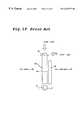
- FIG. 19is a schematic view of a liquid crystal display using the light guide plate.
- a liquid crystal displayis provided with a liquid crystal panel 39 on the side of a light emission surface 34 which diffuses and emits the light of a light guide plate 30 .
- a body of a camerais positioned on the opposite side (the left side of the figure) of the light emission surface of the light guide plate 30 , and a cameraman watches images from the right side of the liquid crystal panel 39 through light emitted from the light emission surface 34 .
- An outer light collecting portion 40composed of a cylindrical lens having a circle shape in cross-section is provided at the upper end of the light guide plate 1 in order to collect outer light as secondary light.
- a surface of this cylindrical lens for collecting outer light(the face formed when the dotted-line A-A′ in the figure moves in vertical direction to the paper) faces to the upper direction of the paper (the direction indicated as “the direction of the surface” in the figure), and is constructed so as to collect light from the upper side effectively.
- the present inventionhas been made for solving the above-mentioned problems and has for its object to reduce power consumption at the main light source by increasing the efficiency to collect outer light.
- the second object of the present inventionis to provide light guide plate which make it possible to abandon the main light source.
- the third object of the present inventionis to provide surface light source using the light guide plate and liquid crystal display.
- the light guide plate of a first embodiment in the present inventionis formed of resin in one body and is provided with an outer light collecting portion to collect outer light, a light emission surface for emitting the outer light collected from the outer light collecting portion, and the outer light collecting portion sticks out of the light emission surface to the light emission direction.
- the light guide plate of a second embodiment in the present inventionis formed of resin in one body and is provided with an outer light collecting portion to collect outer light, a light emission surface for emitting the outer light collected through the outer light collecting portion and a light reflection surface, which is opposite to the light emission surface, for reflecting the outer light collected through the outer light collecting portion, and the outer light collecting portion sticks out of the light emission surface an the light reflection surface.
- the light guide plate of the present inventionwhich is formed of resin in one body is provided with an outer light collecting portion to collect outer light, a light emission surface for emitting the outer light collected through the outer light collecting portion and a light reflection surface, which is opposite to the light emission surface, for reflecting the outer light collected through the outer light collecting portion, and the outer light collecting portion sticks out of the light emission surface and the light reflection surface, and the outer light collecting portion is thicker than the light emission surface and the light reflection surface.
- the light guide plate of the third embodiment in the present inventionis formed of resin in one body and is provided with an outer light collecting portion for collecting outer light at the upper end of the light guide plate, and the surface for collecting outer light of the outer light collecting portion faces to the upper slant direction.
- the light guide plate of the present inventionis formed of resin in one body and is provided with an outer light collecting portion for collecting outer light and a light emission surface for emitting the collected outer light through the outer light collecting portion.
- a first lens portionconsisting a plurality of lenticular unit lenses in a recessed or projected shape is formed on the light emission surface, and the plurality of lenticular unit lenses in the first lens portion are so arranged that their respective ridge lines are nearly parallel to each other and are nearly perpendicular to the longitudinal direction of the outer light collecting portion.
- the vertical angle of a plurality of lenticular unit lenses in the first lens portionis set in the range of 125° to 165° in the light guide plate.
- the vertical angle of a plurality of lenticular unit lenses in the first lens portionis in the vicinity of 150°.
- any one of the above-mentioned light guide plateis provided with a second lens portion consisting a plurality of lenticular unit lenses, which are formed of the same resin as that of the light guide plate, in a recessed or projected shape is formed on the light reflection surface which is opposite to the light emission surface, and the plurality of lenticular unit lenses in the second lens portion are so arranged that their respective ridge lines are nearly parallel to each other and are nearly perpendicular to the ridge lines of the plurality of lenticular unit lenses in the first lens portion.
- the vertical angle of a plurality of lenticular unit lenses in the second lens portionis set in the range of 125° to 165° in the light guide plate.
- the vertical angle of a plurality of lenticular unit lenses in the second lens portionis in the vicinity of 150°.
- the surface light source of the present inventionis provided with each one of the above-mentioned light guide plate and a light source which is mounted on a surface except for the outer light collecting portion and the light emission surface of the light guide plate.
- a liquid crystal display of the present inventionis provided with each one of the above-mentioned light guide plate and a liquid crystal panel mounted near the light emission surface of the light guide plate.
- the outer light collecting portion of the light guide platedoes not stick out of the display screen of the liquid crystal display to the direction of light emission in the liquid crystal display.
- FIG. 1is a perspective view showing a light guide plate according to a first embodiment of the present invention
- FIGS. 2A to 2 Gare schematic views showing a construction of an outer light collecting portion of a light guide plate according to a first embodiment of the present invention
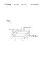
- FIG. 3is a schematic view showing a surface light source using a light guide plate according to a first embodiment of the present invention
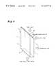
- FIGS. 4A and 4Bare schematic views showing a liquid crystal display using a surface light source shown in FIG. 3;
- FIG. 5is a perspective view showing a light guide plate according to a second embodiment of the present invention.
- FIGS. 6A to 6 Eare schematic views showing a construction of an outer light collecting portion of a light guide plate according to a second embodiment of the present invention.
- FIG. 7is a schematic view showing a surface light source using a light guide plate according to a second embodiment of the present invention.
- FIGS. 8A and 8Bare schematic views showing a liquid crystal display using a surface light source shown in FIG. 7;
- FIG. 9is a perspective view showing a light guide plate according to a third embodiment of the present invention.
- FIG. 10is a schematic view showing a surface light source using a light guide plate according to a third embodiment of the present invention.
- FIG. 11is a schematic view showing a liquid crystal display using a surface light source shown in FIG. 7;
- FIGS. 12A and 12Bare perspective views showing a light guide plate according to the present invention.
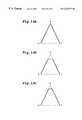
- FIGS. 13A, 13 B and 13 Care schematic views showing a cross-sectional shape of a triangular prism portion
- FIG. 14is a perspective view showing a light guide plate according to the present invention.
- FIG. 15is a graph showing luminance distribution characteristics
- FIG. 16is a graph showing visual angle characteristics
- FIG. 17is a graph showing the change in luminance distribution characteristics with a prism pitch
- FIG. 18is a perspective view showing another light guide plate according to the present invention.
- FIG. 19is a schematic view showing a liquid crystal display using a conventional light guide plate.
- FIG. 1is a perspective view showing a light guide plate according to a first embodiment.
- a light guide plate 1when a body of a light guide plate 1 is formed by resin forming with a mold, an outer light collecting portion 10 , which will be described later, is also formed at the same time.
- the outer light collecting portion 10collects outer light such as the sunlight and light from a lighting apparatus as a secondary light.
- the outer light collecting portion 10is formed so as to stick out of a light emission surface 14 , which will be described later, to the direction to which synthesized light emits (that is, the upper direction in the figure). Accordingly, the surface area of an outer light collecting surface is larger than that of a conventional light guide plate.
- a light incidence surface 12As for a light incidence surface 12 , described as follow, light, irradiated from a light source (not shown) provided so as to be adjacent and approximately parallel to the light incident surface 12 , is incidence. Light sources can be provided on either of both side surfaces 11 to make them light incident surfaces.
- a light reflection surface 13As for a light reflection surface 13 , after resin forming, dot pattern printing is carried out and a reflection plate made from Aluminum or the like (not shown) is mounted to prevent light leakage and raise the reflection efficiency.
- a light emission surface 14As for a light emission surface 14 , light, which is incident from the outer light collecting portion 10 and the light incidence surface 12 , reflects from the light reflection surface 13 and both side surfaces of a light guide plate 1 , and most of the incident light is emitted, in the end, as a synthesized light having the even directivity.
- Leakage prevention materialssuch as white tape, is provided with the side surfaces 11 to prevent the leakage of light.
- the material of the light guide plate 1is selected from transparent materials. Generally, acrylic resin or polycarbonate resin is used.
- the shape of the light guide plateis parallel and flat plate or flat plate having a wedge shape in cross section.
- the thickness of the light guide plateis approximately 1 to 10 mm in general.
- the other transparent materialsinclude acrylic ester such as polymethyl methacrylate and polyacrylic acid methyl, methacrylate ester alone or its copolymers, polyester such as polyethylene terephthalate and polybutylene terephthalate, thermoplastic resin such as polycarbonate, polystyrene, and polymethylpentene, acrylate such as multifunctional urethane acrylate and polyester acrylate cross-linked by ultraviolet rays or electron beams, transparent resin such as unsaturated polyester, transparent glass, and transparent ceramics.
- acrylic estersuch as polymethyl methacrylate and polyacrylic acid methyl
- polyestersuch as polyethylene terephthalate and polybutylene terephthalate
- thermoplastic resinsuch as polycarbonate, polystyrene, and polymethylpentene
- acrylatesuch as multifunctional urethane acrylate and polyester acrylate cross-linked by ultraviolet rays or electron beams
- transparent resinsuch as unsaturated polyester
- FIGS. 2A to 2 Gare front views of an outer light collecting portion of a light guide plate, according to the present invention, to illustrate a shape available, particularly for an outer light collecting portion.
- a light guide plate 1shown in FIG. 2A, has the same shape as the light guide plate 1 shown in FIG. 1 and the left side of the outer light collecting portion 10 has a circle shape in cross section and the right side of the outer light collecting portion 10 has a oblique line shape.
- Both left and right side of an outer light collecting portion of a light guide plate 1shown in FIG. 2B, have an oblique line shape.
- Both left and right side of an outer light collecting portion of a light guide plate 1shown in FIG. 2C, have a circle shape in cross section.
- the left side of the outer light collecting portion 10 in a light guide plate 1shown in FIG. 2D, has a circle shape in cross section and the right side of the outer light collecting portion 10 has an perpendicular line shape.
- the left side of the outer light collecting portion 10 of a light guide plate 1shown in FIG. 2E, has a semicircle shape in cross section and the right side of the outer light collecting portion 10 has a perpendicular line shape.
- the left side of the outer light collecting portion 10 of a light guide plate 1shown in FIG. 2F, has a semicircle shape in cross section and the right side of the outer light collecting portion 10 has a perpendicular line shape.
- a light guide plate 1 shown in FIG. 2Gforms a plurality of fisheye lenses 1 f on the left side of an outer light collecting portion 10 of the light guide plate 1 shown in FIG. 2 B.
- FIG. 1The function of the light guide plate according to the present invention will be described using FIG. 1 .
- Such outer lights as the outside sunlight and the fluorescent light in a roomare incident to the outer light collecting portion of a light guide plate 10 .
- the outer light collecting portion 10sticks out of the light emission surface 14 to the light emission direction. Therefore, the outer light collecting portion has much larger area of a surface of collecting outer light, compared to an outer light collecting portion of a conventional light guide plate (see the figure), and outer light can be received in by an outer light collecting portion effectively. Accordingly, when a liquid crystal display provided with a light guide plate of the present invention is adopted as a viewfinder etc., sufficient lighting can make it unnecessary to turn on a light source, and the reduction of power consumption can be achieved.
- FIG. 3is a schematic view showing a surface light source using a light guide plate according to the first embodiment of the present invention.
- a surface light source 2is composed of the light guide plate 1 , the light source 3 such as a fluorescent tube etc. of the first embodiment, any kind of control circuits (not shown), and so on.
- the control circuitsinclude a circuit which detects the total amount of light emitted from a light emission surface of a light guide plate 1 , adjusts the electric power to optimize the amount of light emission and supplies the electric power to the light source 3 .
- Light emitted from the light source 3reflects from a reflector 4 and enters the inside of the light guide plate 1 through a light incidence surface 12 of a light guide plate 1 and outer light such as the natural light enters the inside of the light guide plate 1 through an outer light collecting portion 10 of a light guide plate 1 .
- Those lightsare reflected from a reflection plate 5 mounted under the light reflection surface 13 and from the side end surfaces 11 , are focused repeatedly, and are emitted from the light emission surface 14 of the light guide plate 1 to a diffusion plate 6 .
- Light that is incident in the diffusion plate 6is diffused uniformly and isotropically in a desired angular range through the diffusion plate 6 and a lens sheet 7 , and is emitted from the lens sheet 7 .
- FIGS. 4A and 4Bare schematic views showing a liquid crystal display provided with a surface light source of the present invention.
- FIG. 4Ashows an outer light collecting portion 10 which sticks out of the display of liquid crystal panel 9 to the light emission direction
- FIG. 4Bshows an outer light collecting portion 10 which does not stick out of the display of liquid crystal panel 9 to the light emission direction.
- an outer light collecting portion 10 of FIG. 4Bmakes it possible to prevent damages on an outer light collecting portion itself and injuries of users and, further, does not interfere good and flexible design, because it does not stand out from the display of liquid crystal panel 9 .
- the liquid crystal display 8comprises a liquid crystal panel 9 and a surface light source 2 of the present invention. Light diffused uniformly and isotropically and emitted from the surface light source 2 enter the liquid crystal panel 9 .
- the liquid crystal displaymay be one that uses only outer light obtained from a light guide plate 1 , removing the light source 3 from the surface light source 2 .
- the light guide plate according to the first embodiment of the present inventionhas an outer light collecting portion that sticks out of the light emission surface and that can enlarge the area of collecting outer light, as compared with a conventional light guide plate. Therefore, it is possible for a light guide plate to collect outer light including the sunlight and a room light as a main light effectively.
- the efficiency of collecting outer lightis improved by using the light guide plate.
- a certain amount of light emissionis obtained, it is possible to reduce the power supplied to the light source, further more, to disuse the light source according to circumstances.
- the outer light collecting portion of a light guide plate that does not stick out of the liquid crystal displaycan secure the safety of a user due to the less factor of causing injuries, and further, prevent damages on the outer light collecting portion itself and maintain the flexibility in design.
- FIG. 5is a perspective view showing a light guide plate according to a second embodiment of the present invention.
- a light guide plate 1 of a second embodimentAs for a light guide plate 1 of a second embodiment as well as a first embodiment, when a body of a light guide plate 1 is formed by resin forming with a mold, an outer light collecting portion 10 a is also formed at the side end of the light guide plate 1 at the same time.
- the light guide plate 1 of the second embodimenthas the same construction as that of the light guide plate 1 of the first embodiment except for the outer light collecting portion 10 a. So the reference numerals are affixed for the same parts, and the explanation is omitted for avoiding duplication of the description.
- the outer light collecting portion 10 asticks out of a light emission surface 14 and a light reflection surface 13 , which will be described later, to the upper and lower direction of the figure. So an area of a surface for collecting outer light is enlarged as compared with a conventional light guide plate.
- the outer light collecting portion 10 ahas an approximate fan shape in cross section and the end of the outer light collecting portion 10 a is a cylindrical lens of a semicircle shape. The effect of a lens enable the outer light collecting portion 10 a to collect outer light not only from the above direction but also from the side direction, the lower slant direction, and the upper slant direction effectively.
- the outer light collecting portion 10 ais not limited to a cylindrical lens of a fan shape, but it may be a trapezoid shape in which a lens is not formed and the surface is flat.
- FIGS. 6A to 6 Eare front views of an outer light collecting portion of a light guide plate, according to the second embodiment of the present invention, to illustrate a shape available, particularly, for an outer light collecting portion.
- a light guide plate 1shown in FIG. 6A, is the same as that shown in FIG. 5 and has an approximate fan shape.
- the left side of the outer light collecting portion 10 ahas a circle shape in cross section and the right side of the outer light collecting portion 10 a has an oblique line shape.
- a light guide plate 1shown in FIG. 6B have an approximate trapezoid shape and the left side of the collecting portion 10 a is flat and the right side of the collecting portion has a oblique line shape.
- Both left and right side of the outer light collecting portion 10 a of a light guide plate 1shown in FIG. 6C, have a circle shape in cross section.
- the left side of the outer light collecting portion 10 a of a light guide plate 1shown in FIG. 6D, has a circle shape in cross sectional and the right side of the outer light collecting portion 10 a has a perpendicular line shape.
- a light guide plate 1 shown in FIG. 6Eforms a plurality of fisheye lenses 10 f on the left side of the outer light collecting portion 10 a in the light guide plate 1 shown in FIG. 6 B.
- the material of the light guide plate 1is selected from transparent materials that are the same as those of the first embodiment. Generally, acrylic resin or polycarbonate resin is used.
- the shape of the light guide plate 1is parallel and flat plate or flat plate having a wedge shape in cross section.
- the thickness of the light guide plateis approximately 1 to 10 mm in general.
- Examples of the other transparent materialsare the same as those of the first embodiment.
- FIG. 7is a schematic view showing a surface light source using a light guide plate according to the second embodiment of the present invention.
- a surface light source 2is composed of the light guide plate 1 , the light source 3 such as a fluorescent tube etc. of the second embodiment, any kind of control circuits (not shown), and so on.
- the control circuitsinclude a circuit which detects the total amount of light emitted from a light emission surface of a light guide plate 1 , adjusts the electric power to optimize the amount of light emission and supplies the electric power to the light source 3 .
- Light emitted from the light source 3reflects from a reflector 4 and enters the inside of the light guide plate 1 through a light incidence surface 12 of a light guide plate 1 and outer light such as the natural light enters the inside of the light guide plate 1 through an outer light collecting portion 10 a of a light guide plate 1 .
- Those lightsare reflected from a reflection plate 5 mounted under the light reflection surface 13 and from the side end surfaces 11 , are focused repeatedly, and are emitted from the light emission surface 14 of the light guide plate 1 to a diffusion plate 6 .
- Light that is incident in the diffusion plate 6is diffused uniformly and isotropically in a desired angular range through the diffusing plate 6 and a lens sheet 7 , and is emitted from the lens sheet 7 .
- FIGS. 8A and 8Bare schematic views showing a liquid crystal display provided with a surface light source of the present invention.
- FIG. 8Ashows an outer light collecting portion 10 a which sticks out of the display of liquid crystal panel 9 to the light emission direction and
- FIG. 8Bshows an outer light collecting portion 10 a which does not stick out of the display of a liquid crystal panel 9 to the light emission direction.
- both of these two liquid crystal displayscan collect outer light effectively, the outer light collecting portion 10 a of FIG. 8B makes it possible to prevent damages on the outer light collecting portion itself and injuries of users and, further, does not interfere good and flexible design, because it does not stand out from the display of the liquid crystal panel 9 .
- the liquid crystal displaymay be one that uses only outer light obtained from a light guide plate 1 , removing a light source 3 from the surface light source 2 .
- FIG. 9is a perspective view showing a light guide plate according to a third embodiment.
- a light guide plate 1 of a third embodimentAs for a light guide plate 1 of a third embodiment as well as a first embodiment, when a body of the light guide plate 1 is formed by resin forming with a mold, an outer light collecting portion 10 b is also formed at the side end of the light guide plate 1 at the same time.
- the light guide plate 1 of the third embodimenthas the same construction as that of the light guide plate 1 of the first embodiment except for the outer light collecting portion 10 b. So the same reference numerals are affixed for the same parts, and the explanation is omitted for avoiding duplication of the description.
- the outer light collecting portion 10 bconsists of a cylindrical lens having a semicircle shape in cross section, and the surface for collecting outer light (the face formed by sliding the dotted line A-A′ to the another side surface 11 in the figure) faces to the direction indicated by the black arrow (the direction indicated as the upper slant direction in the figure). Therefore, outer light from the upper slant direction can be received the most, and further outer light from the above and side direction can be received effectively.
- the outer light collecting portion 10 bis not limited to a cylindrical lens in a circle shape, but it may be a trigonal prism, for example, as long as the surface for collecting outer light faces the upper slant direction.
- the material of the light guide plate 1is selected from transparent materials that are the same as those of the first embodiment. Generally, acrylic resin or polycarbonate resin is used.
- the shape of the light guide plate 1is parallel and flat plate or flat plate having a wedge shape in cross section.
- the thickness of the light guide plateis approximately 1 to 10 mm in general.
- Examples of the other transparent materialsare the same as those of the first embodiment.
- the outside sunlight and such outer lights as the fluorescent light in a roomare incident to an outer light collecting portion 10 b of a light guide plate 1 .
- the surface for collecting outer light of the outer light collecting portion 10 bfaces the upper slant direction, outer light that is incident mainly from the upper slant direction can be received by the outer light collecting portion 10 b effectively as compared to a conventional light guide plate (see FIG. 19 ). Accordingly, when a liquid crystal display provided with a light guide plate of the present invention is adopted as a viewfinder etc., sufficient lighting can make it unnecessary to turn on a light source, and the reduction of power consumption can be achieved.
- FIG. 10is a schematic view showing a surface light source of the present invention.
- a surface light source 2is composed of the light guide plate 1 , the light source 3 such as a fluorescent tube etc. of the present invention, any kind of control circuits (not shown), and so on.
- the control circuitsinclude a circuit which detects the total amount of light emitted from a light emission surface of a light guide plate 1 , adjusts the electric power to optimize the amount of light emission and supplies the electric power to the light source 3 .
- Light emitted from the light source 3reflects from a reflector 4 and enters the inside of the light guide plate 1 through a light incidence surface 12 of a light guide plate 1 and the outer light such as the natural light enters the inside of the light guide plate 1 through an outer light collecting portion 10 b of a light guide plate 1 .
- Those lightsare reflected from a reflection plate 5 mounted under the light reflection surface 13 and from the side end surfaces 11 , are focused repeatedly, and are emitted from the light emission surface 14 of a light guide plate 1 to a diffusion plate 6 .
- Light that is incident in the diffusion plate 6is diffused uniformly and isotropically in a desired angular range through the diffusing plate 6 and a lens sheet 7 and is emitted from the lens sheet 7 .
- FIG. 11is a schematic view showing a liquid crystal display provided with a surface light source of the present invention.
- the liquid crystal display 8comprises a liquid crystal panel 9 and a surface light source 2 of the present invention.
- the lightdiffused uniformly and isotropically and emitted from the surface light source 2 enters a liquid crystal panel 9 .
- the liquid crystal displaymay be one that uses only outer light obtained from the light guide plate 1 , removing the light source 3 from the surface light source 2 .
- the embodimentaims to reduce lenticular lens sheets to one or disuse lens sheets, cut off the cost for parts and fabrication, and provide a surface light source that can reduce the power consumption at the main power supply and disuse a main light surface.
- FIGS. 12A and 12Bare perspective views showing a light guide plate according to the embodiment. The following terms will be defined using the drawings.
- a lenticular unit lensmeans a triangular prism with a triangle formed by vertexes A, B and C taken as its base in FIG. 12A, and a pentagonal prism with a pentagon formed by vertexes A, B, D, E and C taken as its base in FIG. 12 B.
- the lenticular unit lenses 21 illustrated hereinare mere examples, not limitations, and may be a column, a cylindroid or a polygon prism. Although, in FIGS. 12A and 12B, the lenticular unit lens 21 is one in a projected shape, it may be one in a recessed shape, which is not illustrated.
- a triangular prism portion of the lenticular unit lensmeans a triangular prism with a triangle formed by vertexes A, B and C taken as its base in both FIGS. 12A and 12B.
- the vertex of the triangular prism portionmeans a vertex A in both FIGS. 12A and 12B.
- An angle at the vertex A of the triangular prism portionmeans an angle formed by the side connecting the vertexes A and B and the side connecting the vertexes A and C in both FIGS. 12A and 12B.
- FIGS. 13A, 13 B and 13 Care schematic views showing cross-sectional shapes of the triangular prism portion.
- the triangular prism portionis preferably in the shape of an isosceles triangle formed by vertexes A, B and C, as shown in FIG. 13 A. Even if it is changed into a shape of a trapezoid as shown in FIG. 13B because the vertex A is slightly chipped, or it is changed into a shape as shown in FIG. 13C because the vertex A is smoothly curved, for example, the performance of a light guide plate is hardly affected, so that all prisms in these shapes are included in the triangular prism portion in the present invention.
- FIG. 14is a perspective view showing a light guide plate in this embodiment applied to the body in the first embodiment of the present invention.
- a light guide plate 1when a body of the light guide plate 1 is formed by resin forming with a mold, an outer light collecting portion 10 is also formed on the upper end of the light guide plate 1 and further a first lens portion 22 composed by a plurality of lenticular unit lenses 21 is formed at the same time.
- the lenticular unit lenses 21 in the first lens portion 22are triangular prisms, and are so arranged that their respective ridge lines are nearly parallel to each other and are nearly perpendicular to the longitudinal direction of the outer light collecting portion 10 .
- the vertical angle of the triangular prismis set in the range of 125° to 165° on the basis of the results of calculation as described later. If the vertical angle of the triangular prism is in the range of 125° to 165°, the performance of the light guide plate 1 is not affected even if there occur deviation and variation in the size, the pitch, the height and the vertical angle of the triangular prism. Particularly, it is found that luminance distribution characteristics are not greatly changed even if the prism pitch is changed in the range of 10 ⁇ m to 1000 ⁇ m, as shown in FIG. 17 .
- the outer light collecting portion 10collects outer light such as the sunlight and room light as a main light.
- the outer light collecting portion 10sticks out of the first lens portion 22 to the upper direction of the figure. Therefore, an area of the surface for collecting outer light is enlarged as compared with a conventional light guide plate.
- the outer light collecting portion 10has an approximate fan shape in cross section and the end of the outer light collecting portion 10 is a cylindrical lens in a semicircle shape. The effect of a lens enable the outer light collecting portion 10 to collect outer light not only from the above direction but also from the side direction and the upper slant direction effectively.
- the outer light collecting portion 10is not limited to a cylindrical lens of a fan shape, for example, but it may be a flat shape in which a lens is not formed and the surface is flat.
- Light irradiated from the light source (not shown) which is arranged so as to be adjacent and approximately parallel to the light incidence surface 12is incident to the light incidence surface 12 .
- the light sourcescan be provided on either or both of side surfaces 11 to make them light incident surfaces.
- a plurality of cones having an approximate shape of a recessed coneare formed at the same time of resin forming, dot pattern printing is carried out after resin forming, and a reflection plate made from Aluminum or the like (not shown) is mounted to prevent light leakage and raise the reflection efficiency.
- the material of the light guide plate 1is selected from transparent materials. Generally, acrylic resin or polycarbonate resin is used.
- the shape of the light guide plateis parallel and flat plate or flat plate having a wedge shape in cross section.
- the thickness of the light guide plateis approximately 1 to 10 mm in general.
- the other transparent materialsinclude acrylic ester such as polymethyl methacrylate and polyacrylic acid methyl, methacrylate ester alone or its copolymers, polyester such as polyethylene terephthalate and polybutylene terephthalate, thermoplastic resin such as polycarbonate, polystyrene, and polymethylpentene, acrylate such as multifunctional urethane acrylate and polyester acrylate cross-linked by ultraviolet rays or electron beams, transparent resin such as unsaturated polyester, transparent glass, and transparent ceramics.
- acrylic estersuch as polymethyl methacrylate and polyacrylic acid methyl
- polyestersuch as polyethylene terephthalate and polybutylene terephthalate
- thermoplastic resinsuch as polycarbonate, polystyrene, and polymethylpentene
- acrylatesuch as multifunctional urethane acrylate and polyester acrylate cross-linked by ultraviolet rays or electron beams
- transparent resinsuch as unsaturated polyester
- the outside sunlight and such outer lights as the fluorescent light in a roomare incident to a outer light collecting portion 10 of a light guide plate 1 effectively.
- a light sourceWhen a light source is turned on, light that is incident from the light source through a light incidence surface 12 and outer light which is collected from the outer light collecting portion 10 reflects from a light reflection surface 13 and the two side surfaces 11 of the light guide plate 1 .
- the diffused emitted light entered to the direction of a first lens portion 22 which has a function of converging lightare emitted from the first lens portion 22 as a synthesized light having the even directivity in a desired angular range. Accordingly, when a liquid crystal display provided with a light guide plate of the present invention is adopted as a liquid crystal monitor etc. of a digital still camera and a video camera or the like which display images, sufficient lighting can make it unnecessary to turn on a light source, and the reduction of power consumption by such kinds of a camera apparatus itself can be achieved.
- FIG. 14is a graph showing luminance distribution characteristics of a light guide plate of the present invention.
- the horizontal axisrepresents the position of the light guide plate from a lamp as percentage with the length of the light guide plate taken as 100%.
- a position at a value 0is a position at an end surface, which is closest to the lamp, of the light guide plate.
- a position at a value 100is a position at an end surface, which is farthest from the lamp, of the light guide plate.
- the vertical axisrepresents luminance whose unit is not shown, and means that the larger the value is, the brighter it is.
- the graph representing the luminance distribution characteristics shown in FIG. 15is an analysis of the luminance distribution characteristics of the light guide plate conducted using “CODE-V” which is software for optical design and evaluation developed by Optical Research Associates(ORA) Corporation in the United States, and shows the results of simulation of the luminance distribution characteristics in a case where the wavelength of light irradiated from the lamp is 600 nm, typical PMMA having an index of refraction of 1.49 is used as the material of the light guide plate, and the vertical angle of the triangular prism is changed to 90°, 120°, 135°, 150°, 165° and flat (i.e., no triangular prism) as parameters for evaluation.
- CODE-Vis software for optical design and evaluation developed by Optical Research Associates(ORA) Corporation in the United States
- the luminance distribution characteristics in which the vertical angle is 90° to 120°which are vertical angles of the lens sheet used together with a conventional light guide plate, are inferior, as compared with the luminance distribution characteristics in which it is flat. Moreover, the luminance distribution characteristics in which the vertical angle is 135° to 165° are substantially improved, as compared with the luminance distribution characteristics in which it is 90° to 120°. Further, the luminance distribution characteristics in which the vertical angle is 135° to 165° are significantly improved. Particularly in the luminance distribution characteristics in which the vertical angle is in the vicinity of 150°, it can be easily understood that a peak effect appears. Even if the wavelength of light and the index of refraction of the material of the light guide plate are slightly changed, the luminance distribution characteristics made clear herein are not greatly affected.
- FIG. 16is a graph showing visual angle characteristics.
- the horizontal axisrepresents a visual angle corresponding to the light guide plate, where a value “0” (not shown) means a direction perpendicular to the light guide plate, and a value “ ⁇ 90” means a direction level with the light guide plate.
- the vertical axisrepresents luminance whose unit is not shown, and means that the larger the value is, the brighter it is.
- the graph representing the visual angle characteristics shown in FIG. 16is an analysis of the visual angle characteristics of the light guide plate conducted using “CODE-V” in the same manner as described above, and shows the results of simulation of the luminance distribution characteristics in a case where the wavelength of light irradiated from the lamp is 600 nm, typical PMMA having an index of refraction of 1.49 is used as the material of the light guide plate, and the vertical angle of the triangular prism is changed to 90°, 120°, 125°, 135°, 150°, 165° and flat (i.e., no triangular prism) as parameters for evaluation.
- the applicant of the present applicationhas found that the visual angle characteristics are substantially improved when the vertical angle is in the range of 125° to 165° as a result of originally simulating the basic optical design of the light guide plate upon being free from the fixed idea that the vertical angle is in the range of 90° to 120° which are vertical angles of a conventional lens sheet, and has proposed an entirely new light guide plate on the basis of the results.
- FIG. 18is a perspective view showing a light guide plate of the present invention.
- the same reference numeralsis affixed for the elements that have been already described and the explanation for them is omitted.
- a light guide plate 1is provided with a first lens portion 22 and a second lens portion 23 each comprising a plurality of lenticular unit lenses formed of the same resin as that of the light guide plate 1 at the same time when the light guide plate 1 is formed by resin forming with a mold.
- the lenticular unit lenses 21 of the second lens portion 23are triangular prisms as well as those of the first lens portion 22 , and are so arranged that their respective ridge lines are nearly parallel to each other and they are nearly parallel to the longitudinal direction of the outer light collecting portion 10 (that is, they are nearly perpendicular to the lenticular unit lenses 21 of the first lens portion 22 ).
- the vertical angle of the triangular prismis set in the range of 125° to 165°. If the vertical angle of the triangular prism is in the range of 125° to 165°, the performance of the light guide plate 1 is not affected even if there occur deviation and variation in the size, the pitch, the height and the vertical angle of the triangular prism.
- the lower surface of the second lens portion 23is subjected to reflective surface processing by aluminum deposition or the like (not shown) so that it does not transmit light.
- Such outer lights as the outside sunlight and the fluorescent light in a roomare incident to an outer light collecting portion 10 of the light guide plate 1 effectively.
- a light sourceWhen a light source is turned on, light that is incident from the light source through a light incidence surface 12 and outer light which is collected from the outer light collecting portion 10 reflect from the lower surface of the second lens portion 23 and the two side surfaces 11 of the light guide plate 1 .
- the second lens portion 23has a function of making the light uniform within the light guide plate 1 and introduces the diffused light to the direction of the first lens portion 22 .
- the diffused emitted light introduced to the direction of the first lens portion 22 which has a function of focusing lights through the second lens portion 23are emitted from the first lens portion 22 as a synthesized light having the even directivity in the desired angular range. Accordingly, when a liquid crystal display provided with a light guide plate of the present invention is adopted as a liquid crystal monitor etc. of a digital still camera and a video camera or the like which display the image, sufficient lighting can make it unnecessary to turn on a light source, and the reduction of power consumption by such kinds of a camera apparatus itself can be achieved.
- the surface light source using the above-mentioned light guide plateis constructed as the same as that described in FIG. 3 .
- the above-mentioned embodimentdescribes the application of a light guide plate of the first embodiment shown in FIG. 1 . It can be also applied to a light guide plate of the second embodiment in FIG. 5 and the third embodiment in FIG. 9 as well.
- a process in which the light guide plate is formed by using a mold of a first lens portion 22 treated with fine pattering and a mold of the first lens portion 22 and the second lens portion 23 treated with fine patterningis included, and a plurality of lenticular unit lens formed of the same resin as that of a light guide plate is formed at the time of forming.
Landscapes
- Physics & Mathematics (AREA)
- Engineering & Computer Science (AREA)
- General Engineering & Computer Science (AREA)
- General Physics & Mathematics (AREA)
- Optics & Photonics (AREA)
- Planar Illumination Modules (AREA)
- Light Guides In General And Applications Therefor (AREA)
Abstract
Description
Claims (4)
Applications Claiming Priority (8)
| Application Number | Priority Date | Filing Date | Title |
|---|---|---|---|
| JP9300443AJPH11133236A (en) | 1997-10-31 | 1997-10-31 | Light transmission plate, and surface light source and liquid crystal display device using the same |
| JP9-300444 | 1997-10-31 | ||
| JP9300444AJPH11133237A (en) | 1997-10-31 | 1997-10-31 | Light transmission plate, surface light source and liquid crystal display device using the light transmission plate |
| JP9-300443 | 1997-10-31 | ||
| JP9-337077 | 1997-12-08 | ||
| JP33707797AJP3316438B2 (en) | 1997-12-08 | 1997-12-08 | Light guide plate, surface light source and liquid crystal display |
| JP9-341236 | 1997-12-11 | ||
| JP34123697AJP3316441B2 (en) | 1997-12-11 | 1997-12-11 | Light guide plate, surface light source using the light guide plate, liquid crystal display device, and method of manufacturing light guide plate |
Publications (1)
| Publication Number | Publication Date |
|---|---|
| US6273577B1true US6273577B1 (en) | 2001-08-14 |
Family
ID=27479779
Family Applications (1)
| Application Number | Title | Priority Date | Filing Date |
|---|---|---|---|
| US09/183,727Expired - LifetimeUS6273577B1 (en) | 1997-10-31 | 1998-10-30 | Light guide plate, surface light source using the light guide plate, and liquid crystal display using the surface light source |
Country Status (1)
| Country | Link |
|---|---|
| US (1) | US6273577B1 (en) |
Cited By (87)
| Publication number | Priority date | Publication date | Assignee | Title |
|---|---|---|---|---|
| US6360030B1 (en)* | 1996-12-27 | 2002-03-19 | Canon Kabushiki Kaisha | Illumination device and image reading apparatus using the same |
| US6573956B1 (en)* | 1999-09-22 | 2003-06-03 | Kabushiki Kaisha Advanced Display | Liquid crystal display |
| US6626552B2 (en)* | 2001-04-10 | 2003-09-30 | Sanyo Electric Co., Ltd. | Mobile information terminal |
| US20030201702A1 (en)* | 2002-04-26 | 2003-10-30 | Kyu-Seok Kim | Backlight assembly and liquid crystal display apparatus having the same |
| US6654088B2 (en)* | 2000-10-17 | 2003-11-25 | Hitachi, Ltd. | Liquid crystal display device |
| US6712482B2 (en)* | 2000-10-25 | 2004-03-30 | Seiko Epson Corporation | Illumination device and liquid crystal apparatus using the same |
| US20040207822A1 (en)* | 2003-04-15 | 2004-10-21 | Samsung Electronics Co., Ltd. | Projection display |
| USD499835S1 (en) | 2002-10-09 | 2004-12-14 | Hon Hai Precision Ind. Co., Ltd. | Light guide plate |
| US20050041413A1 (en)* | 2003-08-22 | 2005-02-24 | Chun-Yu Lee | Light guide plate with a reflective means and process for forming the same |
| US20050213001A1 (en)* | 2000-11-14 | 2005-09-29 | Sharp Kabushiki Kaisha | Reflective display device and prism array sheet |
| US20050275327A1 (en)* | 2004-04-03 | 2005-12-15 | Samsung Sdi Co., Ltd. | Flat panel display |
| US20070139621A1 (en)* | 2005-12-19 | 2007-06-21 | Lightwedge, Llc | Compact illumination and magnification device |
| USD545983S1 (en) | 2005-09-23 | 2007-07-03 | Lightwedge, Llc | Compact device for illuminating a flat surface |
| CN100339748C (en)* | 2004-05-25 | 2007-09-26 | 友达光电股份有限公司 | Backlight module and its fixing mechanism |
| US20080123019A1 (en)* | 2006-11-24 | 2008-05-29 | Sumitomo Chemical Company, Limited | Light diffuser plate, surface emission light source apparatus and liquid crystal display |
| CN100419535C (en)* | 2005-03-09 | 2008-09-17 | 鸿富锦精密工业(深圳)有限公司 | display device |
| US20080268235A1 (en)* | 2007-04-25 | 2008-10-30 | Sumitomo Chemical Company, Limited | Light diffuser plate |
| CN100483204C (en)* | 2004-04-17 | 2009-04-29 | 鸿富锦精密工业(深圳)有限公司 | light guide plate |
| EP2068181A1 (en)* | 2007-12-07 | 2009-06-10 | Qualcomm Mems Technologies, Inc. | Light illumination of displays with front light guide and coupling elements |
| US20090225394A1 (en)* | 2004-09-27 | 2009-09-10 | Idc, Llc | System and method of illuminating interferometric modulators using backlighting |
| US7603001B2 (en) | 2006-02-17 | 2009-10-13 | Qualcomm Mems Technologies, Inc. | Method and apparatus for providing back-lighting in an interferometric modulator display device |
| US20090268122A1 (en)* | 2005-11-28 | 2009-10-29 | Sharp Kabushiki Kaisha | Backlight device and liquid crystal display device using the same |
| US20090296194A1 (en)* | 2004-09-27 | 2009-12-03 | Idc, Llc | Optical films for directing light towards active areas of displays |
| US7706050B2 (en) | 2004-03-05 | 2010-04-27 | Qualcomm Mems Technologies, Inc. | Integrated modulator illumination |
| US20100103488A1 (en)* | 2006-10-10 | 2010-04-29 | Qualcomm Mems Technologies, Inc. | Display device with diffractive optics |
| US20100118563A1 (en)* | 2008-11-12 | 2010-05-13 | Au Optronics (Suzhou) Corp | Light guide plate and display apparatus |
| US7719747B2 (en) | 2004-09-27 | 2010-05-18 | Qualcomm Mems Technologies, Inc. | Method and post structures for interferometric modulation |
| US7733439B2 (en) | 2007-04-30 | 2010-06-08 | Qualcomm Mems Technologies, Inc. | Dual film light guide for illuminating displays |
| US20100141869A1 (en)* | 2008-12-08 | 2010-06-10 | 3M Innovative Properties Company | Passive and hybrid daylight-coupled backlights for sunlight viewable displays |
| US7750886B2 (en) | 2004-09-27 | 2010-07-06 | Qualcomm Mems Technologies, Inc. | Methods and devices for lighting displays |
| US7766498B2 (en) | 2006-06-21 | 2010-08-03 | Qualcomm Mems Technologies, Inc. | Linear solid state illuminator |
| US7777954B2 (en) | 2007-01-30 | 2010-08-17 | Qualcomm Mems Technologies, Inc. | Systems and methods of providing a light guiding layer |
| US7845841B2 (en) | 2006-08-28 | 2010-12-07 | Qualcomm Mems Technologies, Inc. | Angle sweeping holographic illuminator |
| US7855827B2 (en) | 2006-10-06 | 2010-12-21 | Qualcomm Mems Technologies, Inc. | Internal optical isolation structure for integrated front or back lighting |
| US20100328578A1 (en)* | 2009-06-26 | 2010-12-30 | Biernath Rolf W | Passive and hybrid daylight-coupled n-stack and collapsible backlights for sunlight viewable displays |
| US7864395B2 (en) | 2006-10-27 | 2011-01-04 | Qualcomm Mems Technologies, Inc. | Light guide including optical scattering elements and a method of manufacture |
| US20110019258A1 (en)* | 2008-02-13 | 2011-01-27 | Nokia Corporation | Display device and a method for illuminating a light modulator array of a display device |
| US20110025727A1 (en)* | 2009-08-03 | 2011-02-03 | Qualcomm Mems Technologies, Inc. | Microstructures for light guide illumination |
| US7907319B2 (en) | 1995-11-06 | 2011-03-15 | Qualcomm Mems Technologies, Inc. | Method and device for modulating light with optical compensation |
| US20110116012A1 (en)* | 2009-11-18 | 2011-05-19 | 3M Innovative Properties Company | Passive daylight-coupled backlight with turning film having prisms with chaos for sunlight viewable displays |
| US20110175553A1 (en)* | 2008-10-10 | 2011-07-21 | Qualcomm Mems Technologies, Inc. | Distributed lighting control system |
| US20110175533A1 (en)* | 2008-10-10 | 2011-07-21 | Qualcomm Mems Technologies, Inc | Distributed illumination system |
| US20110227967A1 (en)* | 2008-12-05 | 2011-09-22 | Mooyeon Kim | Display device, controlling method for the display device and standing apparatus |
| US8040589B2 (en) | 2008-02-12 | 2011-10-18 | Qualcomm Mems Technologies, Inc. | Devices and methods for enhancing brightness of displays using angle conversion layers |
| US8049951B2 (en) | 2008-04-15 | 2011-11-01 | Qualcomm Mems Technologies, Inc. | Light with bi-directional propagation |
| US8061882B2 (en) | 2006-10-06 | 2011-11-22 | Qualcomm Mems Technologies, Inc. | Illumination device with built-in light coupler |
| US8107155B2 (en) | 2006-10-06 | 2012-01-31 | Qualcomm Mems Technologies, Inc. | System and method for reducing visual artifacts in displays |
| US20120074450A1 (en)* | 2009-08-13 | 2012-03-29 | Taica Corporation | Optical gel member, assembling method of optical device and optical device using the same |
| US8172417B2 (en) | 2009-03-06 | 2012-05-08 | Qualcomm Mems Technologies, Inc. | Shaped frontlight reflector for use with display |
| US8231257B2 (en) | 2009-01-13 | 2012-07-31 | Qualcomm Mems Technologies, Inc. | Large area light panel and screen |
| US8348489B2 (en) | 2008-01-30 | 2013-01-08 | Qualcomm Mems Technologies, Inc. | Thin illumination system |
| US8384852B2 (en) | 2010-11-22 | 2013-02-26 | 3M Innovative Properties Company | Hybrid daylight-coupled backlights for sunlight viewable displays |
| US8402647B2 (en) | 2010-08-25 | 2013-03-26 | Qualcomm Mems Technologies Inc. | Methods of manufacturing illumination systems |
| TWI391717B (en)* | 2008-03-03 | 2013-04-01 | Univ Nat Chunghsing | A light guide plate with a partition gradient |
| TWI406019B (en)* | 2008-05-27 | 2013-08-21 | Radiant Opto Electronics Corp | The structure of the light guide plate |
| US20130294105A1 (en)* | 2012-05-03 | 2013-11-07 | Audi Ag | Light element having a targeted influence on edge optics |
| US8654061B2 (en) | 2008-02-12 | 2014-02-18 | Qualcomm Mems Technologies, Inc. | Integrated front light solution |
| US8721149B2 (en) | 2008-01-30 | 2014-05-13 | Qualcomm Mems Technologies, Inc. | Illumination device having a tapered light guide |
| US8798425B2 (en) | 2007-12-07 | 2014-08-05 | Qualcomm Mems Technologies, Inc. | Decoupled holographic film and diffuser |
| US8833996B2 (en)* | 2012-09-13 | 2014-09-16 | Quarkstar Llc | Illumination systems providing direct and indirect illumination |
| US8833969B2 (en) | 2011-08-08 | 2014-09-16 | Quarkstar Llc | Indirect direct troffer luminaire |
| US20140308515A1 (en)* | 2013-04-10 | 2014-10-16 | Hon Hai Precision Industry Co., Ltd. | Adhesive tape |
| US8872085B2 (en) | 2006-10-06 | 2014-10-28 | Qualcomm Mems Technologies, Inc. | Display device having front illuminator with turning features |
| US8902484B2 (en) | 2010-12-15 | 2014-12-02 | Qualcomm Mems Technologies, Inc. | Holographic brightness enhancement film |
| US8928967B2 (en) | 1998-04-08 | 2015-01-06 | Qualcomm Mems Technologies, Inc. | Method and device for modulating light |
| WO2015010076A1 (en)* | 2013-07-18 | 2015-01-22 | Quarkstar Llc | Illumination device having a light guide with leaky side surfaces |
| US8941631B2 (en) | 2007-11-16 | 2015-01-27 | Qualcomm Mems Technologies, Inc. | Simultaneous light collection and illumination on an active display |
| US8971675B2 (en) | 2006-01-13 | 2015-03-03 | Qualcomm Mems Technologies, Inc. | Interconnect structure for MEMS device |
| US8979349B2 (en) | 2009-05-29 | 2015-03-17 | Qualcomm Mems Technologies, Inc. | Illumination devices and methods of fabrication thereof |
| US20150092385A1 (en)* | 2013-10-01 | 2015-04-02 | Samsung Display Co., Ltd. | Display apparatus |
| US9019183B2 (en) | 2006-10-06 | 2015-04-28 | Qualcomm Mems Technologies, Inc. | Optical loss structure integrated in an illumination apparatus |
| US9019590B2 (en) | 2004-02-03 | 2015-04-28 | Qualcomm Mems Technologies, Inc. | Spatial light modulator with integrated optical compensation structure |
| US9025235B2 (en) | 2002-12-25 | 2015-05-05 | Qualcomm Mems Technologies, Inc. | Optical interference type of color display having optical diffusion layer between substrate and electrode |
| US9081125B2 (en) | 2011-08-08 | 2015-07-14 | Quarkstar Llc | Illumination devices including multiple light emitting elements |
| TWI494615B (en)* | 2007-03-28 | 2015-08-01 | Cheil Ind Inc | Optical prism sheet having a certain roughness thereon |
| US9110289B2 (en) | 1998-04-08 | 2015-08-18 | Qualcomm Mems Technologies, Inc. | Device for modulating light with multiple electrodes |
| US9206956B2 (en) | 2013-02-08 | 2015-12-08 | Quarkstar Llc | Illumination device providing direct and indirect illumination |
| US9326348B2 (en) | 2007-06-15 | 2016-04-26 | Sharp Kabushiki Kaisha | Solid state illumination system |
| US9354377B2 (en) | 2013-09-17 | 2016-05-31 | Quarkstar Llc | Light guide illumination device with light divergence modifier |
| US9410680B2 (en) | 2013-04-19 | 2016-08-09 | Quarkstar Llc | Illumination devices with adjustable optical elements |
| US9507071B1 (en)* | 2015-05-20 | 2016-11-29 | Wuhan China Star Optoelectronics Technology Co., Ltd. | Light guide plate and backlight module |
| US20170023725A1 (en)* | 2015-07-23 | 2017-01-26 | Stanley Electric Co., Ltd. | Surface light source device and prism sheet |
| US9746173B2 (en) | 2012-09-13 | 2017-08-29 | Quarkstar Llc | Illumination devices including enclosure panels with luminaire modules |
| US20190235156A1 (en)* | 2018-01-30 | 2019-08-01 | Beijing Boe Display Technology Co., Ltd. | Backlight module and display device |
| CN112984450A (en)* | 2021-03-22 | 2021-06-18 | 江西省交通科学研究院有限公司 | Intelligent light guide system suitable for tunnel |
| US11280453B2 (en)* | 2018-09-17 | 2022-03-22 | Lmpg Inc. | Wedge-shaped light guides for luminaries and luminaire assemblies incorporating same |
| CN115201960A (en)* | 2022-07-07 | 2022-10-18 | 杭州科能捷瑞智能科技有限公司 | A backlight light guide device |
Citations (5)
| Publication number | Priority date | Publication date | Assignee | Title |
|---|---|---|---|---|
| US4460939A (en)* | 1980-10-17 | 1984-07-17 | Fuji Photo Optical Co., Ltd. | Device for producing a line of illumination |
| US5027258A (en)* | 1989-06-19 | 1991-06-25 | Inotec Gmbh Gesellschaft Fur Innovative Technik | Display unit |
| JPH0511249A (en) | 1991-07-08 | 1993-01-19 | Hitachi Ltd | Liquid crystal display |
| US5808708A (en)* | 1994-12-15 | 1998-09-15 | Sharp Kabushiki Kaisha | Lighting apparatus |
| US5810463A (en)* | 1994-11-28 | 1998-09-22 | Nikon Corporation | Illumination device |
- 1998
- 1998-10-30USUS09/183,727patent/US6273577B1/ennot_activeExpired - Lifetime
Patent Citations (5)
| Publication number | Priority date | Publication date | Assignee | Title |
|---|---|---|---|---|
| US4460939A (en)* | 1980-10-17 | 1984-07-17 | Fuji Photo Optical Co., Ltd. | Device for producing a line of illumination |
| US5027258A (en)* | 1989-06-19 | 1991-06-25 | Inotec Gmbh Gesellschaft Fur Innovative Technik | Display unit |
| JPH0511249A (en) | 1991-07-08 | 1993-01-19 | Hitachi Ltd | Liquid crystal display |
| US5810463A (en)* | 1994-11-28 | 1998-09-22 | Nikon Corporation | Illumination device |
| US5808708A (en)* | 1994-12-15 | 1998-09-15 | Sharp Kabushiki Kaisha | Lighting apparatus |
Cited By (145)
| Publication number | Priority date | Publication date | Assignee | Title |
|---|---|---|---|---|
| US7907319B2 (en) | 1995-11-06 | 2011-03-15 | Qualcomm Mems Technologies, Inc. | Method and device for modulating light with optical compensation |
| US6360030B1 (en)* | 1996-12-27 | 2002-03-19 | Canon Kabushiki Kaisha | Illumination device and image reading apparatus using the same |
| US9110289B2 (en) | 1998-04-08 | 2015-08-18 | Qualcomm Mems Technologies, Inc. | Device for modulating light with multiple electrodes |
| US8928967B2 (en) | 1998-04-08 | 2015-01-06 | Qualcomm Mems Technologies, Inc. | Method and device for modulating light |
| US6573956B1 (en)* | 1999-09-22 | 2003-06-03 | Kabushiki Kaisha Advanced Display | Liquid crystal display |
| US6654088B2 (en)* | 2000-10-17 | 2003-11-25 | Hitachi, Ltd. | Liquid crystal display device |
| US6712482B2 (en)* | 2000-10-25 | 2004-03-30 | Seiko Epson Corporation | Illumination device and liquid crystal apparatus using the same |
| US7019801B2 (en) | 2000-11-14 | 2006-03-28 | Sharp Kabushiki Kaisha | Reflective display device and prism array sheet |
| US7151580B2 (en) | 2000-11-14 | 2006-12-19 | Sharp Kabushiki Kaisha | Reflective display device and prism array sheet |
| US20050213001A1 (en)* | 2000-11-14 | 2005-09-29 | Sharp Kabushiki Kaisha | Reflective display device and prism array sheet |
| US6626552B2 (en)* | 2001-04-10 | 2003-09-30 | Sanyo Electric Co., Ltd. | Mobile information terminal |
| US6929392B2 (en)* | 2002-04-26 | 2005-08-16 | Samsung Electronics Co., Ltd. | Backlight assembly and liquid crystal display apparatus having the same |
| CN100374933C (en)* | 2002-04-26 | 2008-03-12 | 三星电子株式会社 | Backlight assembly and liquid crystal display device with the backlight assembly |
| US20030201702A1 (en)* | 2002-04-26 | 2003-10-30 | Kyu-Seok Kim | Backlight assembly and liquid crystal display apparatus having the same |
| USD499835S1 (en) | 2002-10-09 | 2004-12-14 | Hon Hai Precision Ind. Co., Ltd. | Light guide plate |
| US9025235B2 (en) | 2002-12-25 | 2015-05-05 | Qualcomm Mems Technologies, Inc. | Optical interference type of color display having optical diffusion layer between substrate and electrode |
| CN100405127C (en)* | 2003-04-15 | 2008-07-23 | 三星电子株式会社 | projection display |
| US20040207822A1 (en)* | 2003-04-15 | 2004-10-21 | Samsung Electronics Co., Ltd. | Projection display |
| US7066601B2 (en) | 2003-04-15 | 2006-06-27 | Samsung Electronics Co., Ltd. | Projection display having an illumination module and an optical modulator |
| US20050041413A1 (en)* | 2003-08-22 | 2005-02-24 | Chun-Yu Lee | Light guide plate with a reflective means and process for forming the same |
| US7136562B2 (en) | 2003-08-22 | 2006-11-14 | Hon Hai Precision Ind. Co., Ltd. | Light guide plate with a reflective means and process for forming the same |
| US9019590B2 (en) | 2004-02-03 | 2015-04-28 | Qualcomm Mems Technologies, Inc. | Spatial light modulator with integrated optical compensation structure |
| US7880954B2 (en) | 2004-03-05 | 2011-02-01 | Qualcomm Mems Technologies, Inc. | Integrated modulator illumination |
| US7706050B2 (en) | 2004-03-05 | 2010-04-27 | Qualcomm Mems Technologies, Inc. | Integrated modulator illumination |
| US20050275327A1 (en)* | 2004-04-03 | 2005-12-15 | Samsung Sdi Co., Ltd. | Flat panel display |
| US7527398B2 (en)* | 2004-04-03 | 2009-05-05 | Samsung Mobile Display Co., Ltd. | Flat panel display |
| CN100483204C (en)* | 2004-04-17 | 2009-04-29 | 鸿富锦精密工业(深圳)有限公司 | light guide plate |
| CN100339748C (en)* | 2004-05-25 | 2007-09-26 | 友达光电股份有限公司 | Backlight module and its fixing mechanism |
| US7986451B2 (en) | 2004-09-27 | 2011-07-26 | Qualcomm Mems Technologies, Inc. | Optical films for directing light towards active areas of displays |
| US20090225394A1 (en)* | 2004-09-27 | 2009-09-10 | Idc, Llc | System and method of illuminating interferometric modulators using backlighting |
| US7750886B2 (en) | 2004-09-27 | 2010-07-06 | Qualcomm Mems Technologies, Inc. | Methods and devices for lighting displays |
| US8411026B2 (en) | 2004-09-27 | 2013-04-02 | Qualcomm Mems Technologies, Inc. | Methods and devices for lighting displays |
| US20090296194A1 (en)* | 2004-09-27 | 2009-12-03 | Idc, Llc | Optical films for directing light towards active areas of displays |
| US8040588B2 (en) | 2004-09-27 | 2011-10-18 | Qualcomm Mems Technologies, Inc. | System and method of illuminating interferometric modulators using backlighting |
| US7719747B2 (en) | 2004-09-27 | 2010-05-18 | Qualcomm Mems Technologies, Inc. | Method and post structures for interferometric modulation |
| CN100419535C (en)* | 2005-03-09 | 2008-09-17 | 鸿富锦精密工业(深圳)有限公司 | display device |
| USD545983S1 (en) | 2005-09-23 | 2007-07-03 | Lightwedge, Llc | Compact device for illuminating a flat surface |
| US20090268122A1 (en)* | 2005-11-28 | 2009-10-29 | Sharp Kabushiki Kaisha | Backlight device and liquid crystal display device using the same |
| US7894012B2 (en)* | 2005-11-28 | 2011-02-22 | Sharp Kabushiki Kaisha | Backlight device and liquid crystal display device using the same |
| US7575329B2 (en) | 2005-12-19 | 2009-08-18 | Lightwedge, Llc | Compact illumination and magnification device |
| US20070139621A1 (en)* | 2005-12-19 | 2007-06-21 | Lightwedge, Llc | Compact illumination and magnification device |
| US8971675B2 (en) | 2006-01-13 | 2015-03-03 | Qualcomm Mems Technologies, Inc. | Interconnect structure for MEMS device |
| US7603001B2 (en) | 2006-02-17 | 2009-10-13 | Qualcomm Mems Technologies, Inc. | Method and apparatus for providing back-lighting in an interferometric modulator display device |
| US7766498B2 (en) | 2006-06-21 | 2010-08-03 | Qualcomm Mems Technologies, Inc. | Linear solid state illuminator |
| US7845841B2 (en) | 2006-08-28 | 2010-12-07 | Qualcomm Mems Technologies, Inc. | Angle sweeping holographic illuminator |
| US8107155B2 (en) | 2006-10-06 | 2012-01-31 | Qualcomm Mems Technologies, Inc. | System and method for reducing visual artifacts in displays |
| US8061882B2 (en) | 2006-10-06 | 2011-11-22 | Qualcomm Mems Technologies, Inc. | Illumination device with built-in light coupler |
| US8872085B2 (en) | 2006-10-06 | 2014-10-28 | Qualcomm Mems Technologies, Inc. | Display device having front illuminator with turning features |
| US7855827B2 (en) | 2006-10-06 | 2010-12-21 | Qualcomm Mems Technologies, Inc. | Internal optical isolation structure for integrated front or back lighting |
| US9019183B2 (en) | 2006-10-06 | 2015-04-28 | Qualcomm Mems Technologies, Inc. | Optical loss structure integrated in an illumination apparatus |
| US20100103488A1 (en)* | 2006-10-10 | 2010-04-29 | Qualcomm Mems Technologies, Inc. | Display device with diffractive optics |
| US7864395B2 (en) | 2006-10-27 | 2011-01-04 | Qualcomm Mems Technologies, Inc. | Light guide including optical scattering elements and a method of manufacture |
| US20080123019A1 (en)* | 2006-11-24 | 2008-05-29 | Sumitomo Chemical Company, Limited | Light diffuser plate, surface emission light source apparatus and liquid crystal display |
| US7777954B2 (en) | 2007-01-30 | 2010-08-17 | Qualcomm Mems Technologies, Inc. | Systems and methods of providing a light guiding layer |
| TWI494615B (en)* | 2007-03-28 | 2015-08-01 | Cheil Ind Inc | Optical prism sheet having a certain roughness thereon |
| US20080268235A1 (en)* | 2007-04-25 | 2008-10-30 | Sumitomo Chemical Company, Limited | Light diffuser plate |
| US7733439B2 (en) | 2007-04-30 | 2010-06-08 | Qualcomm Mems Technologies, Inc. | Dual film light guide for illuminating displays |
| US9326348B2 (en) | 2007-06-15 | 2016-04-26 | Sharp Kabushiki Kaisha | Solid state illumination system |
| US8941631B2 (en) | 2007-11-16 | 2015-01-27 | Qualcomm Mems Technologies, Inc. | Simultaneous light collection and illumination on an active display |
| US7949213B2 (en) | 2007-12-07 | 2011-05-24 | Qualcomm Mems Technologies, Inc. | Light illumination of displays with front light guide and coupling elements |
| EP2068181A1 (en)* | 2007-12-07 | 2009-06-10 | Qualcomm Mems Technologies, Inc. | Light illumination of displays with front light guide and coupling elements |
| EP2068182A1 (en)* | 2007-12-07 | 2009-06-10 | Qualcomm Mems Technologies, Inc. | Light illumination of displays with front light guide and coupling elements |
| WO2009073555A1 (en)* | 2007-12-07 | 2009-06-11 | Qualcomm Mems Technologies, Inc. | Light illumination of displays with front light guide and coupling elements |
| US8798425B2 (en) | 2007-12-07 | 2014-08-05 | Qualcomm Mems Technologies, Inc. | Decoupled holographic film and diffuser |
| US20090147535A1 (en)* | 2007-12-07 | 2009-06-11 | Qualcomm Incorporated | Light illumination of displays with front light guide and coupling elements |
| US9244212B2 (en) | 2008-01-30 | 2016-01-26 | Qualcomm Mems Technologies, Inc. | Illumination device having a tapered light guide |
| US8740439B2 (en) | 2008-01-30 | 2014-06-03 | Qualcomm Mems Technologies, Inc. | Thin illumination system |
| US8721149B2 (en) | 2008-01-30 | 2014-05-13 | Qualcomm Mems Technologies, Inc. | Illumination device having a tapered light guide |
| US8348489B2 (en) | 2008-01-30 | 2013-01-08 | Qualcomm Mems Technologies, Inc. | Thin illumination system |
| US9448353B2 (en) | 2008-01-30 | 2016-09-20 | Qualcomm Mems Technologies, Inc. | Illumination device having a tapered light guide |
| US9395479B2 (en) | 2008-01-30 | 2016-07-19 | Qualcomm Mems Technologies, Inc. | Illumination device having a tapered light guide |
| US8654061B2 (en) | 2008-02-12 | 2014-02-18 | Qualcomm Mems Technologies, Inc. | Integrated front light solution |
| US8040589B2 (en) | 2008-02-12 | 2011-10-18 | Qualcomm Mems Technologies, Inc. | Devices and methods for enhancing brightness of displays using angle conversion layers |
| US20110019258A1 (en)* | 2008-02-13 | 2011-01-27 | Nokia Corporation | Display device and a method for illuminating a light modulator array of a display device |
| US8331006B2 (en) | 2008-02-13 | 2012-12-11 | Nokia Corporation | Display device and a method for illuminating a light modulator array of a display device |
| TWI391717B (en)* | 2008-03-03 | 2013-04-01 | Univ Nat Chunghsing | A light guide plate with a partition gradient |
| US8049951B2 (en) | 2008-04-15 | 2011-11-01 | Qualcomm Mems Technologies, Inc. | Light with bi-directional propagation |
| TWI406019B (en)* | 2008-05-27 | 2013-08-21 | Radiant Opto Electronics Corp | The structure of the light guide plate |
| US8674616B2 (en) | 2008-10-10 | 2014-03-18 | Qualcomm Mems Technologies, Inc. | Distributed illumination system |
| US20110175553A1 (en)* | 2008-10-10 | 2011-07-21 | Qualcomm Mems Technologies, Inc. | Distributed lighting control system |
| US20110175533A1 (en)* | 2008-10-10 | 2011-07-21 | Qualcomm Mems Technologies, Inc | Distributed illumination system |
| US20100118563A1 (en)* | 2008-11-12 | 2010-05-13 | Au Optronics (Suzhou) Corp | Light guide plate and display apparatus |
| US8162525B2 (en) | 2008-11-12 | 2012-04-24 | Au Optronics (Suzhou) Corp | Light guide plate and display apparatus |
| CN101403807B (en)* | 2008-11-12 | 2011-08-17 | 友达光电(苏州)有限公司 | Light conducting plate, backlight module and display equipment |
| US20110227967A1 (en)* | 2008-12-05 | 2011-09-22 | Mooyeon Kim | Display device, controlling method for the display device and standing apparatus |
| US9137479B2 (en)* | 2008-12-05 | 2015-09-15 | Lg Electronics Inc. | Display device, controlling method for the display device and standing apparatus |
| US8149351B2 (en) | 2008-12-08 | 2012-04-03 | 3M Innovative Properties Company | Passive and hybrid daylight-coupled backlights for sunlight viewable displays |
| US20100141869A1 (en)* | 2008-12-08 | 2010-06-10 | 3M Innovative Properties Company | Passive and hybrid daylight-coupled backlights for sunlight viewable displays |
| US8439546B2 (en) | 2009-01-13 | 2013-05-14 | Qualcomm Mems Technologies, Inc. | Large area light panel and screen |
| US8231257B2 (en) | 2009-01-13 | 2012-07-31 | Qualcomm Mems Technologies, Inc. | Large area light panel and screen |
| US8172417B2 (en) | 2009-03-06 | 2012-05-08 | Qualcomm Mems Technologies, Inc. | Shaped frontlight reflector for use with display |
| US9121979B2 (en) | 2009-05-29 | 2015-09-01 | Qualcomm Mems Technologies, Inc. | Illumination devices and methods of fabrication thereof |
| US8979349B2 (en) | 2009-05-29 | 2015-03-17 | Qualcomm Mems Technologies, Inc. | Illumination devices and methods of fabrication thereof |
| US8339542B2 (en) | 2009-06-26 | 2012-12-25 | 3M Innovative Properties Company | Passive and hybrid daylight-coupled N-stack and collapsible backlights for sunlight viewable displays |
| US20100328578A1 (en)* | 2009-06-26 | 2010-12-30 | Biernath Rolf W | Passive and hybrid daylight-coupled n-stack and collapsible backlights for sunlight viewable displays |
| US20110025727A1 (en)* | 2009-08-03 | 2011-02-03 | Qualcomm Mems Technologies, Inc. | Microstructures for light guide illumination |
| US20120074450A1 (en)* | 2009-08-13 | 2012-03-29 | Taica Corporation | Optical gel member, assembling method of optical device and optical device using the same |
| US20110116012A1 (en)* | 2009-11-18 | 2011-05-19 | 3M Innovative Properties Company | Passive daylight-coupled backlight with turning film having prisms with chaos for sunlight viewable displays |
| US8228463B2 (en) | 2009-11-18 | 2012-07-24 | 3M Innovative Properties Company | Passive daylight-coupled backlight with turning film having prisms with chaos for sunlight viewable displays |
| US8402647B2 (en) | 2010-08-25 | 2013-03-26 | Qualcomm Mems Technologies Inc. | Methods of manufacturing illumination systems |
| US8384852B2 (en) | 2010-11-22 | 2013-02-26 | 3M Innovative Properties Company | Hybrid daylight-coupled backlights for sunlight viewable displays |
| US8902484B2 (en) | 2010-12-15 | 2014-12-02 | Qualcomm Mems Technologies, Inc. | Holographic brightness enhancement film |
| US8833969B2 (en) | 2011-08-08 | 2014-09-16 | Quarkstar Llc | Indirect direct troffer luminaire |
| US11703631B2 (en) | 2011-08-08 | 2023-07-18 | Quarkstar Llc | Illumination devices including multiple light emitting elements |
| US10823905B2 (en) | 2011-08-08 | 2020-11-03 | Quarkstar Llc | Illumination devices including multiple light emitting elements |
| US9081125B2 (en) | 2011-08-08 | 2015-07-14 | Quarkstar Llc | Illumination devices including multiple light emitting elements |
| US10859758B2 (en) | 2011-08-08 | 2020-12-08 | Quarkstar Llc | Illumination devices including multiple light emitting elements |
| US8899808B2 (en) | 2011-08-08 | 2014-12-02 | Quarkstar Llc | Lightguide luminaire module for direct and indirect illumination |
| US9028120B2 (en) | 2011-08-08 | 2015-05-12 | Quarkstar Llc | Illumination devices including multiple light emitting elements |
| US20130294105A1 (en)* | 2012-05-03 | 2013-11-07 | Audi Ag | Light element having a targeted influence on edge optics |
| US8833996B2 (en)* | 2012-09-13 | 2014-09-16 | Quarkstar Llc | Illumination systems providing direct and indirect illumination |
| US10190762B2 (en) | 2012-09-13 | 2019-01-29 | Quarkstar Llc | Devices for workspace illumination having a panel forming an enclosure and a plurality of light emitters with primary and secondary optics |
| US9846272B2 (en) | 2012-09-13 | 2017-12-19 | Quarkstar Llc | Illumination systems providing direct and indirect illumination |
| US9746173B2 (en) | 2012-09-13 | 2017-08-29 | Quarkstar Llc | Illumination devices including enclosure panels with luminaire modules |
| US9206956B2 (en) | 2013-02-08 | 2015-12-08 | Quarkstar Llc | Illumination device providing direct and indirect illumination |
| US20140308515A1 (en)* | 2013-04-10 | 2014-10-16 | Hon Hai Precision Industry Co., Ltd. | Adhesive tape |
| US9410680B2 (en) | 2013-04-19 | 2016-08-09 | Quarkstar Llc | Illumination devices with adjustable optical elements |
| US10180240B2 (en) | 2013-04-19 | 2019-01-15 | Quarkstar Llc | Illumination devices with adjustable optical elements |
| US10838138B2 (en) | 2013-07-18 | 2020-11-17 | Quarkstar Llc | Luminaire module with multiple light guide elements |
| US9459398B2 (en) | 2013-07-18 | 2016-10-04 | Quarkstar Llc | Illumination device in which source light injection is non-parallel to device's optical axis |
| US10473847B2 (en) | 2013-07-18 | 2019-11-12 | Quarkstar Llc | Illumination device having a light guide with leaky side surfaces |
| WO2015010076A1 (en)* | 2013-07-18 | 2015-01-22 | Quarkstar Llc | Illumination device having a light guide with leaky side surfaces |
| US9335462B2 (en) | 2013-07-18 | 2016-05-10 | Quarkstar Llc | Luminaire module with multiple light guide elements |
| US10288798B2 (en) | 2013-07-18 | 2019-05-14 | Quarkstar Llc | Illumination device in which source light injection is non-parallel to device's optical axis |
| US10132988B2 (en) | 2013-07-18 | 2018-11-20 | Quarkstar Llc | Luminaire module with multiple light guide elements |
| US9664839B2 (en) | 2013-09-17 | 2017-05-30 | Quarkstar Llc | Illumination device for direct-indirect illumination |
| US10495807B2 (en) | 2013-09-17 | 2019-12-03 | Quarkstar Llc | Light guide illumination device for direct-indirect illumination |
| US11693174B2 (en) | 2013-09-17 | 2023-07-04 | Quarkstar Llc | Illumination device for direct-indirect illumination |
| US10203446B2 (en) | 2013-09-17 | 2019-02-12 | Quarkstar Llc | Light guide illumination device with light divergence modifier |
| US9891371B2 (en) | 2013-09-17 | 2018-02-13 | Quarkstar Llc | Light guide illumination device for direct-indirect illumination |
| US10094969B2 (en) | 2013-09-17 | 2018-10-09 | Quarkstar Llc | Illumination device for direct-indirect illumination |
| US9557030B2 (en) | 2013-09-17 | 2017-01-31 | Quarkstar Llc | Light guide illumination device for direct-indirect illumination |
| US11150400B2 (en) | 2013-09-17 | 2021-10-19 | Quarkstar Llc | Illumination device for direct-indirect illumination |
| US10705284B2 (en) | 2013-09-17 | 2020-07-07 | Quarkstar Llc | Luminaire with luminaire module |
| US10725229B2 (en) | 2013-09-17 | 2020-07-28 | Quarkstar Llc | Illumination device for direct-indirect illumination |
| US9354377B2 (en) | 2013-09-17 | 2016-05-31 | Quarkstar Llc | Light guide illumination device with light divergence modifier |
| US20150092385A1 (en)* | 2013-10-01 | 2015-04-02 | Samsung Display Co., Ltd. | Display apparatus |
| US9507071B1 (en)* | 2015-05-20 | 2016-11-29 | Wuhan China Star Optoelectronics Technology Co., Ltd. | Light guide plate and backlight module |
| US20170023725A1 (en)* | 2015-07-23 | 2017-01-26 | Stanley Electric Co., Ltd. | Surface light source device and prism sheet |
| US10036844B2 (en)* | 2015-07-23 | 2018-07-31 | Stanley Electric Co., Ltd. | Surface light source device and prism sheet |
| US20190235156A1 (en)* | 2018-01-30 | 2019-08-01 | Beijing Boe Display Technology Co., Ltd. | Backlight module and display device |
| US10871609B2 (en)* | 2018-01-30 | 2020-12-22 | Beijing Boe Display Technology Co., Ltd. | Backlight module and display device |
| US11280453B2 (en)* | 2018-09-17 | 2022-03-22 | Lmpg Inc. | Wedge-shaped light guides for luminaries and luminaire assemblies incorporating same |
| CN112984450A (en)* | 2021-03-22 | 2021-06-18 | 江西省交通科学研究院有限公司 | Intelligent light guide system suitable for tunnel |
| CN115201960A (en)* | 2022-07-07 | 2022-10-18 | 杭州科能捷瑞智能科技有限公司 | A backlight light guide device |
Similar Documents
| Publication | Publication Date | Title |
|---|---|---|
| US6273577B1 (en) | Light guide plate, surface light source using the light guide plate, and liquid crystal display using the surface light source | |
| US5999685A (en) | Light guide plate and surface light source using the light guide plate | |
| JP2706574B2 (en) | Backlight device using an array of microprisms | |
| JP3213496B2 (en) | Lighting equipment | |
| JP3123006B2 (en) | Surface light source and liquid crystal display | |
| US7374312B2 (en) | Bottom lighting backlight module having uniform illumination and process for manufacturing the same | |
| JPH10246805A (en) | Optical sheet for controlling diffused light, backlight device, and liquid crystal display device | |
| JP3316441B2 (en) | Light guide plate, surface light source using the light guide plate, liquid crystal display device, and method of manufacturing light guide plate | |
| JP2003036713A (en) | Surface light source device | |
| JPH11250713A (en) | Light guide plate and plane lighting system | |
| JPH11133214A (en) | Optical sheet, optical sheet laminate, surface light source device, and transmission type display device | |
| KR100253635B1 (en) | Light guiding body, method of manufacturing thereof, and plane-light source | |
| KR100438524B1 (en) | BackLight Unit | |
| JP3532212B2 (en) | Irradiation equipment using multi-sided micro prism array | |
| TW573177B (en) | Illumination panel and display device equipped with the illumination panel | |
| JP2006040710A (en) | Light guide plate and planar lighting system using it | |
| JPH07159607A (en) | Optical control sheet and surface light emitting device provided therewith | |
| JPH10339815A (en) | Light guide plate, manufacture of light guide plate, and surface light source using the light guid plate | |
| JP3778839B2 (en) | Light guide plate and flat illumination device | |
| JPH10300908A (en) | Lens sheet, surface light source device, and transmissive display device | |
| JP2003021726A (en) | Light guide, surface light source device and liquid crystal display device using the same | |
| KR100989167B1 (en) | Backlight unit | |
| JPH10123517A (en) | Light transmission plate and plane illuminator | |
| JP2002124114A (en) | Surface light source device and liquid crystal display device using the same | |
| JP3515336B2 (en) | Light guide plate, surface light source using the light guide plate, and liquid crystal display device |
Legal Events
| Date | Code | Title | Description |
|---|---|---|---|
| AS | Assignment | Owner name:SANYO ELECTRIC CO., LTD., JAPAN Free format text:ASSIGNMENT OF ASSIGNORS INTEREST;ASSIGNORS:GOTO, YOUICHIRO;NOSE, TORU;SATO, MICHIAKI;AND OTHERS;REEL/FRAME:009560/0733 Effective date:19981016 | |
| STCF | Information on status: patent grant | Free format text:PATENTED CASE | |
| FPAY | Fee payment | Year of fee payment:4 | |
| FEPP | Fee payment procedure | Free format text:PAYOR NUMBER ASSIGNED (ORIGINAL EVENT CODE: ASPN); ENTITY STATUS OF PATENT OWNER: LARGE ENTITY | |
| FPAY | Fee payment | Year of fee payment:8 | |
| AS | Assignment | Owner name:FOLTORA SERVICE LIMITED LIABILITY COMPANY, DELAWAR Free format text:ASSIGNMENT OF ASSIGNORS INTEREST;ASSIGNOR:SANYO ELECTRIC CO., LTD.;REEL/FRAME:023245/0550 Effective date:20090706 | |
| FEPP | Fee payment procedure | Free format text:PAYER NUMBER DE-ASSIGNED (ORIGINAL EVENT CODE: RMPN); ENTITY STATUS OF PATENT OWNER: LARGE ENTITY Free format text:PAYOR NUMBER ASSIGNED (ORIGINAL EVENT CODE: ASPN); ENTITY STATUS OF PATENT OWNER: LARGE ENTITY | |
| FPAY | Fee payment | Year of fee payment:12 | |
| AS | Assignment | Owner name:CALLAHAN CELLULAR L.L.C., DELAWARE Free format text:MERGER;ASSIGNOR:FOLTORA SERVICE LIMITED LIABILITY COMPANY;REEL/FRAME:037529/0938 Effective date:20150826 | |
| AS | Assignment | Owner name:HANGER SOLUTIONS, LLC, GEORGIA Free format text:ASSIGNMENT OF ASSIGNORS INTEREST;ASSIGNOR:INTELLECTUAL VENTURES ASSETS 158 LLC;REEL/FRAME:051486/0425 Effective date:20191206 | |
| AS | Assignment | Owner name:INTELLECTUAL VENTURES ASSETS 158 LLC, DELAWARE Free format text:ASSIGNMENT OF ASSIGNORS INTEREST;ASSIGNOR:CALLAHAN CELLULAR L.L.C.;REEL/FRAME:051727/0155 Effective date:20191126 |