US6273550B1 - Inkjet printer capable of minimizing chromatic variation in adjacent print swaths when printing color images in bidirectional mode - Google Patents
Inkjet printer capable of minimizing chromatic variation in adjacent print swaths when printing color images in bidirectional modeDownload PDFInfo
- Publication number
- US6273550B1 US6273550B1US09/511,854US51185400AUS6273550B1US 6273550 B1US6273550 B1US 6273550B1US 51185400 AUS51185400 AUS 51185400AUS 6273550 B1US6273550 B1US 6273550B1
- Authority
- US
- United States
- Prior art keywords
- head
- firing
- segments
- inkjet
- scan direction
- Prior art date
- Legal status (The legal status is an assumption and is not a legal conclusion. Google has not performed a legal analysis and makes no representation as to the accuracy of the status listed.)
- Expired - Lifetime
Links
Images


Classifications
- B—PERFORMING OPERATIONS; TRANSPORTING
- B41—PRINTING; LINING MACHINES; TYPEWRITERS; STAMPS
- B41J—TYPEWRITERS; SELECTIVE PRINTING MECHANISMS, i.e. MECHANISMS PRINTING OTHERWISE THAN FROM A FORME; CORRECTION OF TYPOGRAPHICAL ERRORS
- B41J19/00—Character- or line-spacing mechanisms
- B41J19/14—Character- or line-spacing mechanisms with means for effecting line or character spacing in either direction
- B41J19/142—Character- or line-spacing mechanisms with means for effecting line or character spacing in either direction with a reciprocating print head printing in both directions across the paper width
- B41J19/147—Colour shift prevention
Definitions
- the present inventionrelates to an inkjet printer designed to print color images comprised of process colors as defined by the subtractive color model, and more particularly to an inkjet printer capable of reducing and/or eliminating chromatic variation in adjacent print swaths when printing in a bidirectional mode.
- an inkjet printeris possible to print a high-precision image at a high-speed by firing inks on a print medium such as paper from a print head.
- the inkjet printershave grown popular for the public use along with the current widespread use of computers.
- the most employed color printersare such types that are capable of firing several color inks from one print head. In particular, they can be used mostly for printing images with multi-color/multi-tone processed by the computers.
- the print headis scanned in a direction across a print paper (the main scan direction) in order to print a printable region per scan.
- the print paperis advanced in a direction perpendicular to the main scan direction (the sub scan direction).
- the print headgenerally comprises a plurality of head-segments arrayed in the main scan direction. Each head-segment responds to each ink color. Each head-segment has a plurality of nozzles arranged at different locations in the sub scan direction. A color printing is performed in accordance with the subtractive color model.
- the subtractive color modelis represented typically with a combination, CMY, of cyan (C), magenta (M) and yellow (Y) inks or a more common combination, CMYK, of CMY plus black (K) ink.
- CMYKCMY plus black
- LMlight-density magenta
- LClight-density cyan
- spot colorsorange, green, red and blue.
- a common configurationwould currently be a print head with four head-segments, one per color, arranged in a nozzle order of KCMY so that when printing in a unidirectional mode the K ink is the first to be placed on the print paper, followed by C, M, and finally Y ink.
- each alternate print swath(the reverse print swath) would be created by placing the Y ink on the paper first, followed by M, C, and finally K ink contrarily to the forward print swath.
- the KCMY method of printingis based on the notion that optimum color reproduction is achieved with the subtractive color process by printing the darkest color, black (K), first followed by a brighter color than black, cyan(C), and so on.
- Kdarkest color
- Cblack
- LC and LMfollow Y in the optimum order of lay down.
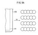
- FIGS. 9A-Cillustrate a theoretical model of an interleaved print swath using a print head with a vertical dot pitch of ⁇ fraction (1/18) ⁇ th inch, printing with a horizontal resolution of 360 dots-per-inch (dpi).
- the print head 100is then stepped a certain distance (for example, a 1 ⁇ 2-tall print swath) down in the sub scan direction as shown in FIG. 9B, and the print head 100 travels reverse on a second pass in the main scan direction.
- inksare fired from the ink nozzles 101 to create a printed part with a horizontal resolution of 360 dpi and a vertical resolution of 180 dpi.
- a 1 ⁇ 2-tall full dot print swath SWT 1is created with both horizontal and vertical resolutions of 360 dpi.
- all dotsare printed in YMCK order: the darkest color is printed finally.
- the print head 100is further stepped a certain distance down in the sub scan direction as shown in FIG. 9C, the print head 100 travels on the first pass again (shown by an arrow R 2 ).
- inksare fired from the ink nozzles 101 to create a printed part with a horizontal resolution of 360 dpi and a vertical resolution of 180 dpi.
- another 1 ⁇ 2-tall full dot print swath SWT 2is created with both horizontal and vertical resolutions of 360 dpi.
- all dotsare printed in KCMY order: the brightest color is printed again finally.
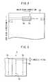
- Dot gainoccurs when an ink droplet of a given size increases in diameter as it dries on the substrate surface. This mechanism is necessary to ensure optimum image quality and color saturation; without adequate dot gain, a printed image will appear “washed out,” since too much of the underlying surface (typically white in color) would show through between the gaps in the dots.
- FIG. 10details the dot gain in the above theoretical model.
- the present inventionis made in consideration of such the disadvantages and accordingly has an object to provide an inkjet printer capable of effectively preventing chromatic variations such as banding due to color overlapping (or overlaying) order variations during printing in a bidirectional mode.
- the present inventionis provided with an inkjet printer, which comprises an inkjet head having a plurality of nozzles arrayed in the main scan direction, each for firing a different color ink.
- the inkjet printeralso comprise head control means for driving the inkjet head relative to a print medium in the main scan direction and the sub scan direction perpendicular to the main scan direction and for providing the inkjet head with firing pulses to fire inks in synchronization with the driving said inkjet head. Droplets of the inks fired from the nozzles for respective colors are overlapped (or overlaid) at each dot-forming position on the print medium to form a color image.
- the inkjet headincludes at least one nozzle for firing a mid-bright color ink and at least one nozzle for firing the brightest color ink so that the nozzle for firing the brightest color ink is located downstream from the nozzle for firing a mid-bright color ink when the inkjet head travels in the main scan direction regardless to both directional passes.
- the control meansprovides the inkjet head with the firing pulses in such a manner that a combination of the nozzles for firing a mid-bright and the brightest color inks in case of the inkjet head traveling on a first directional pass in the main scan direction differs from that in case of said inkjet head traveling on a second directional pass opposite to the first directional pass and that said inks are fired onto one dot-forming position from the nozzle for firing a mid-bright color ink first followed by the nozzle for firing the brightest color ink in both cases of the first and second directional passes.
- the inkjet head for the inkjet printer according to the present inventionmay include the following types.
- a first examplewould be an inkjet head, which preferably includes at least one nozzle for firing the darkest color ink arrayed in the main scan direction so that the nozzle for firing the darkest color ink is located upstream to the nozzle for firing a mid-bright color ink when the inkjet head travels in the main scan direction regardless to both directional passes.
- control meansmay preferably provides a firing pulse to said nozzle for firing a mid-bright color ink after providing a firing pulse to the nozzle for firing the darkest color ink when the inkjet head travels on the first directional pass.
- a second examplewould be an inkjet head, which includes six head-segments arrayed in the main scan direction, each head-segment having a plurality of nozzles arranged at different locations in the sub scan direction.
- the six head-segmentscontains two sets of head-segments, each set consisting of two head-segments for firing the darkest and brightest color inks and located outside two inner head-segments for firing it mid-color inks.
- control meansmay preferably provide the firing pulses, with respect to one dot-forming position, to the head-segment for firing the darkest color ink in the preceding set, the head-segment for firing a mid-color ink, and the head-segment for firing the brightest color ink in the following set, in this order.
- a third examplewould be an inkjet head, which may include four head-segments arrayed in the main scan direction, two head-segments for firing the brightest color inks respectively located outside two inner head-segments for firing mid-color inks.
- control meansmay preferably provide the firing pulses, with respect to one dot-forming position, to the head-segment for firing a mid-color ink and the following head-segment for firing the brightest color ink, in this order.
- the colors of the inks fired from the nozzles in the inkjet heads according to the present inventionmay preferably be that the brightest color is yellow (Y) and the mid-colors are cyan (C) and magenta (M).
- the colors of the inks fired from the nozzles in the first and second inkjet headsmay preferably be that the darkest color is black (K), the brightest color is yellow (Y) and the mid-colors are cyan (C) and magenta (M).
- the colors of the inks fired from the nozzles in the second inkjet headmay preferably be that the darkest color is black (K).
- the control meansprovides the firing pulses alternately to black head-segments contained in the respective sets to realize a double speed monochromic printing compared to color printing.
- the inkjet nozzle array of the inkjet head in the inkjet printeris modified to control the ink firing order. This enables to print one dot position in a maintained ink firing order when the inkjet head travels on either of both directional passes in the main scan direction. Therefore, it is possible to reduce and/or eliminate chromatic variations such as banding due to the ink overlapping order.
- FIG. 1is a block diagram showing a partial configuration of an inkjet printer according to an embodiment of the present invention
- FIG. 2illustrates motions of the inkjet head relative to a print paper in the above printer
- FIG. 3exemplifies an arrangement of nozzles of the inkjet head in the above printer
- FIG. 4Aexemplifies a first arrangement of the inkjet head and method of driving the same in the above printer and FIG. 4B illustrates the order ink dots are laid upon the paper for the L pass and the R pass;
- FIGS. 5A and 5Bexemplify other head-segment arrangement of the inkjet head in the above printer
- FIGS. 6A and 6Bexemplify right and left pass drive methods for monochrome printing by the inkjet head in the above printer.
- FIG. 7Aexemplifies another arrangement of the inkjet head and method of driving the same in the above printer and FIG. 7B illustrates the order ink dots are laid upon the paper for the L pass and the R pass;
- FIG. 8exemplifies a different arrangement of the inkjet head in the above printer
- FIG. 9Ashows a theoretical model in case of printing in an interleaving mode by the conventional inkjet printer
- FIG. 9Bshows the theoretical model in case of printing in the interleaving mode by the conventional inkjet printer
- FIG. 9Cshows the theoretical model in case of printing in the interleaving mode by the conventional inkjet printer.
- FIG. 10Adetails theoretical dot gain for the left pass and FIG. 10B details theoretical dot gain for the right pass.
- FIG. 1is a block diagram showing a partial configuration of an inkjet printer according to an embodiment of the present invention.
- Image data to be printed outsuch as TIFF, JPEG, MR, MMR and CALS, sent from the non-depicted host system is supplied to a CPU 1 .
- the CPU 1converts the input image data into bitmap data through decoding, color converting and tone processing, and stores the result in a bitmap memory 2 .
- the bitmap data stored in the bitmap memory 2is printed out onto a non-depicted print paper by an inkjet head 5 that is driven under control of a head controller 7 .
- the head controller 7comprises a gate array 3 , a head driver 4 and a timing fence unit 6 .
- the gate array 3outputs timing signals for driving the head, to the head driver 4 .
- the head driver 4drives the inkjet head 5 in a direction across the print paper (the main scan direction) and also drives the print paper in a direction perpendicular to the main scan direction (the sub scan direction) based on the timing signals.
- the timing fence unit 6includes a linear encoder to detect a position of the inkjet head 5 and outputs a timing fence signal TP to the gate array 3 when the inkjet head 5 travels every certain distance in the main scan direction.
- the gate array 3outputs the timing signals to the head driver 4 based on the timing fence signal TP.
- the gate array 3also outputs firing pulses FP for determining ink firing timings, to the inkjet head 5 based on the timing fence signal TP.
- FIG. 2illustrates motions of the inkjet head 5 relative to a print paper 20 .
- the inkjet head 5is driven forward and reverse in the main scan direction on the print paper 20 .
- the print paper 20is driven in the sub scan direction at each end of forward and reverse operations of the inkjet head 5 .
- the inkjet head 5consists of a plurality of head-segments 5 a arrayed in the main scan direction for firing different color inks.
- Each head-segment 5 aconsists of a plurality of nozzles 5 b for firing the same color inks as shown in FIG. 3 .
- these nozzles 5 bcan be arranged in an array along the sub scan direction, they are located in such a zigzag manner that every nozzle alternates its position in the main scan direction as depicted for the convenience of arrangement of the nozzles.
- FIG. 4exemplifies a first arrangement of the inkjet head 5 and method of driving it in the above printer.
- the inkjet head 5comprises two sets of head-segment groups 5 C 1 and 5 C 2 arrayed in the main scan direction as shown in FIG. 4 A.
- One head-segment group 5 C 1includes three head-segments 5 a (K 1 , Y 2 , C 3 ) for firing KYC color inks, respectively.
- the other head-segment group 5 C 2includes three head-segments 5 a (M 4 , Y 5 , K 6 ) for firing MYK color inks, respectively.
- Each head-segment 5 acan be driven independently.
- the head-segment groups 5 C 1 and 5 C 2may respectively be composed of a three-color composite head that includes three head-segments 5 a.
- the inkjet head 5travels in a direction shown with an arrow L (a right-to-left movement: hereinafter referred to as an L-pass), the head-segments K 1 , C 3 , M 4 and YS fire inks in turn so that overlapped inks can print KCMY.
- L-passa right-to-left movement: hereinafter referred to as an L-pass
- the head-segments K 6 , M 4 , C 3 and Y 2fire inks in turn so that overlapped inks can print KMCY.
- a combination of specific colors (for example, red and green) in the bidirectional print modeeasily causes noticeable chromatic variations in general. In particular, this phenomenon becomes extremely noticeable when black (K) ink is employed even a slight amount. Accordingly, chromatic variations when alternately printing KCMY and KMCY using the inkjet head 5 as configured in this embodiment are less noticeable than when alternately printing KCMY and YMCK using the conventional inkjet head with KCMY array. Namely, by preventing the ink order of K and Y in the printed result from reversing, chromatic variations in adjacent print swaths can be minimized and thus chromatic variations can be eliminated in almost all colors.
- the head-segment group 5 C 1may include three head-segments 5 a (Y 1 , K 2 , C 3 ) for firing YKC color inks and the head-segment group 5 C 2 may include three head-segments 5 a (M 4 , K 5 , Y 6 ) for firing MKY color inks as shown in FIG. 5 A.
- the head-segment group 5 C 1may also include three head-segments 5 a (K 1 , Y 2 , C 3 ) for firing KYC color inks and the head-segment group 5 C 2 may also include three head-segments 5 a (M 4 , KS, Y 6 ) for firing MKY color inks as shown in FIG. 5 B. It is also possible to minimize chromatic variations in this case by firing from the head-segment K 1 , C 3 , M 4 and Y 6 in turn on the L-pass and from the head-segments K 5 , M 4 , C 3 and Y 2 in turn on the R-pass.
- inkjet head 5 of 6-head-segment typeincludes two K color head-segments 5 a in the main scan direction
- a high-speed monochrome printingcan be achieved at about double the normal print speed as shown in FIG. 6 .
- Thisis performed by driving only head-segments K 1 and K 6 in the inkjet head 5 of FIG. 4, transporting the inkjet head 5 at a double speed of the ink firing frequency, and applying firing pulses so that K 1 and K 6 may operate alternately on every other dot.
- a head transport speed (HTS) of 22.2 inches/second (ips)would be sufficient to print, for example, with a horizontal resolution of 360 dpi, with a print nozzle pulse rate of 8 kHz (8000 pulses/second/nozzle).
- HTShead transport speed
- two print headscan be positioned inline so that one head prints odd dots and the other head prints even dots.
- a high-speed monochrome modecan be achieved at an HTS of 44.4 ips.
- two inkjet headsmust have equal number of inkjet nozzles and equal nozzle pitches and each nozzle must have its own driver.
- FIG. 7exemplifies another arrangement of the inkjet head 5 and method of driving it in the above printer.
- This inkjet head 5comprises four head-segments 5 a (Y 1 , C 2 , M 3 , Y 4 ) for firing YCMY color inks as shown in FIG. 7 A.
- a common design for many low-cost inkjet printersis to use a single array of four heads, or a single composite head with four independent nozzle segments.
- the printeris equipped with C, M, Y, and K inks, and printing is performed in KCMY fashion.
- the K segmentis not absolutely necessary.
- the standard color model for subtractive coloris CMY, not CMYK, although K is added for improved text quality and to better control image contrast.
- the method of this embodimentis intended to balance image quality and speed, by trading the quality gain of adding K with the quality lost to chromatic errors generated in bidirectional mode.
- the inkjet head 5When the inkjet head 5 travels in the L-pass as shown in FIG. 7A, the head-segments C 2 , M 3 and Y 4 fire inks in turn to print on the print paper 20 with overlapped CMY inks as shown in FIG. 7 B.
- the head-segments M 3 , C 2 and Y 1fire inks in turn to print on the print paper 20 with overlapped CMY inks as shown in FIG. 7 B.
- the inkjet head 5that consists of four print heads but does not include K ink can achieve an optimum bidirectional printing.
- FIG. 8Ashows a possible configuration, in which one head-segment group SC consists of four head-segments 5 a (K 1 , C 2 , M 3 , Y 4 ) for firing KCMY color inks and the other head-segment group 5 C 2 four head-segments 5 a (Y 5 , M 6 , C 7 , K 8 ) for firing YMCK color inks.
- FIG. 8Ashows a possible configuration, in which one head-segment group SC consists of four head-segments 5 a (K 1 , C 2 , M 3 , Y 4 ) for firing KCMY color inks and the other head-segment group 5 C 2 four head-segments 5 a (Y 5 , M 6 , C 7 , K 8 ) for firing YMCK color inks.
- FIG. 8Ashows a possible configuration, in which one head-segment group SC consists of four head
- FIG. 8Bshows another possible configuration that consists of seven head-segments 5 a (K 1 , C 2 , M 3 , Y 4 , M 5 , C 6 , K 7 ) for firing KCMYMCK color inks.
- FIG. 8Cshows a further possible configuration that consists of seven head-segments 5 a (Y 1 , M 2 , C 3 , K 4 , C 5 , M 6 , Y 7 ) for firing YMCKCMY color inks.
- the inkjet head 5 that does not include Kmay also be configured with five head-segments 5 a (C 1 , M 2 , Y 3 , M 4 , C 5 ) for firing CMYMC color inks, for example, as shown in FIG. 8 D.
- head-segments 5 aC 1 , M 2 , Y 3 , M 4 , C 5
Landscapes
- Ink Jet (AREA)
Abstract
Description
Claims (6)
Priority Applications (1)
| Application Number | Priority Date | Filing Date | Title |
|---|---|---|---|
| US09/511,854US6273550B1 (en) | 2000-02-23 | 2000-02-23 | Inkjet printer capable of minimizing chromatic variation in adjacent print swaths when printing color images in bidirectional mode |
Applications Claiming Priority (1)
| Application Number | Priority Date | Filing Date | Title |
|---|---|---|---|
| US09/511,854US6273550B1 (en) | 2000-02-23 | 2000-02-23 | Inkjet printer capable of minimizing chromatic variation in adjacent print swaths when printing color images in bidirectional mode |
Publications (1)
| Publication Number | Publication Date |
|---|---|
| US6273550B1true US6273550B1 (en) | 2001-08-14 |
Family
ID=24036718
Family Applications (1)
| Application Number | Title | Priority Date | Filing Date |
|---|---|---|---|
| US09/511,854Expired - LifetimeUS6273550B1 (en) | 2000-02-23 | 2000-02-23 | Inkjet printer capable of minimizing chromatic variation in adjacent print swaths when printing color images in bidirectional mode |
Country Status (1)
| Country | Link |
|---|---|
| US (1) | US6273550B1 (en) |
Cited By (18)
| Publication number | Priority date | Publication date | Assignee | Title |
|---|---|---|---|---|
| US6354693B1 (en)* | 1999-03-22 | 2002-03-12 | Hewlett-Packard Company | Printing of color ink under and over black text and graphics areas |
| US20030090539A1 (en)* | 2001-10-25 | 2003-05-15 | Vutek, Inc. | Multi-speed, multi-resolution print heads |
| US6812953B2 (en)* | 2002-01-24 | 2004-11-02 | Hewlett-Packard Development Company, L.P. | System for reducing the effect of aerodynamic induced errors in a drop-on-demand printing system |
| US20050018012A1 (en)* | 2003-06-13 | 2005-01-27 | Canon Kabushiki Kaisha | Ink jet printing apparatus |
| US20050030337A1 (en)* | 2000-01-25 | 2005-02-10 | Canon Kabushiki Kaisha | Bidirectional printing method and apparatus with reduced color unevenness |
| US6860586B2 (en)* | 2000-09-12 | 2005-03-01 | Sharp Kabushiki Kaisha | Image forming apparatus of ink-jet type and image forming method of ink-jet type |
| US6866365B1 (en) | 2004-04-01 | 2005-03-15 | Eastman Kodak Company | Bi-directional color printer and method of printing |
| US6896356B1 (en)* | 1999-09-30 | 2005-05-24 | Canon Kabushiki Kaisha | Print apparatus and printing method for forming a color image by applying different color inks to a printing material using a recording head |
| US20050250869A1 (en)* | 2004-05-06 | 2005-11-10 | Agfa-Gevaert N.V. | Radiation-curable ink-jet printing |
| US20070285451A1 (en)* | 2006-05-09 | 2007-12-13 | Canon Kabushiki Kaisha | Inkjet printer and inkjet printing method |
| US20080158281A1 (en)* | 2006-12-27 | 2008-07-03 | Canon Kabushiki Kaisha | Image forming apparatus and control method thereof |
| US20090066772A1 (en)* | 2003-10-29 | 2009-03-12 | Konica Minolta Medical & Graphic, Inc. | Ink jet recording apparatus |
| EP1547773A4 (en)* | 2002-05-22 | 2010-03-17 | Seiko Epson Corp | LIQUID JET DEVICE |
| US20100149258A1 (en)* | 2008-12-17 | 2010-06-17 | Canon Kabushiki Kaisha | Ink jet print head and printing method and apparatus using the same |
| US8777375B2 (en)* | 2012-02-21 | 2014-07-15 | Dip-Tech Ltd | Printing system |
| JP2016013700A (en)* | 2008-11-12 | 2016-01-28 | セイコーエプソン株式会社 | Printing device, printing method, and, computer program |
| EP3067209A1 (en)* | 2015-03-02 | 2016-09-14 | Mimaki Engineering Co., Ltd. | Inkjet recording device and inkjet recording method |
| JP2018192642A (en)* | 2017-05-12 | 2018-12-06 | キヤノン株式会社 | Image processing apparatus, image processing method, and program |
Citations (13)
| Publication number | Priority date | Publication date | Assignee | Title |
|---|---|---|---|---|
| US4207579A (en) | 1979-01-08 | 1980-06-10 | The Mead Corporation | Reciprocating paper handling apparatus for use in an ink jet copier |
| US4528576A (en) | 1982-04-15 | 1985-07-09 | Canon Kabushiki Kaisha | Recording apparatus |
| US4593295A (en)* | 1982-06-08 | 1986-06-03 | Canon Kabushiki Kaisha | Ink jet image recording device with pitch-shifted recording elements |
| JPH0247075A (en) | 1988-08-08 | 1990-02-16 | Minolta Camera Co Ltd | Recorder |
| US4952942A (en)* | 1986-05-29 | 1990-08-28 | Canon Kabushiki Kaisha | Ink jet recording method with improved tone by recording yellow first |
| JPH0345351A (en) | 1989-07-13 | 1991-02-26 | Matsushita Electric Ind Co Ltd | Color printer |
| EP0610096A2 (en) | 1993-02-05 | 1994-08-10 | Canon Kabushiki Kaisha | Ink jet recording apparatus |
| EP0646460A1 (en) | 1993-09-30 | 1995-04-05 | Canon Kabushiki Kaisha | Ink-jet printer and printing system capable of printing on clothes and papers, ink to be used in the system and production method for producing article with employing the system |
| EP0661870A1 (en) | 1994-01-03 | 1995-07-05 | Xerox Corporation | Method and apparatus for liquid ink recording of images with black ink and color inks |
| JPH07195715A (en) | 1993-12-29 | 1995-08-01 | Katsuragawa Electric Co Ltd | Color inkjet printer |
| JPH08295034A (en) | 1995-04-27 | 1996-11-12 | Canon Inc | Color recorder |
| US5949453A (en) | 1993-10-29 | 1999-09-07 | Hewlett-Packard Company | Mixed resolution printing for color and monochrome printers |
| EP0955174A2 (en) | 1998-05-07 | 1999-11-10 | Hewlett-Packard Company | Bi-directional printing with controlled hue shifts |
- 2000
- 2000-02-23USUS09/511,854patent/US6273550B1/ennot_activeExpired - Lifetime
Patent Citations (13)
| Publication number | Priority date | Publication date | Assignee | Title |
|---|---|---|---|---|
| US4207579A (en) | 1979-01-08 | 1980-06-10 | The Mead Corporation | Reciprocating paper handling apparatus for use in an ink jet copier |
| US4528576A (en) | 1982-04-15 | 1985-07-09 | Canon Kabushiki Kaisha | Recording apparatus |
| US4593295A (en)* | 1982-06-08 | 1986-06-03 | Canon Kabushiki Kaisha | Ink jet image recording device with pitch-shifted recording elements |
| US4952942A (en)* | 1986-05-29 | 1990-08-28 | Canon Kabushiki Kaisha | Ink jet recording method with improved tone by recording yellow first |
| JPH0247075A (en) | 1988-08-08 | 1990-02-16 | Minolta Camera Co Ltd | Recorder |
| JPH0345351A (en) | 1989-07-13 | 1991-02-26 | Matsushita Electric Ind Co Ltd | Color printer |
| EP0610096A2 (en) | 1993-02-05 | 1994-08-10 | Canon Kabushiki Kaisha | Ink jet recording apparatus |
| EP0646460A1 (en) | 1993-09-30 | 1995-04-05 | Canon Kabushiki Kaisha | Ink-jet printer and printing system capable of printing on clothes and papers, ink to be used in the system and production method for producing article with employing the system |
| US5949453A (en) | 1993-10-29 | 1999-09-07 | Hewlett-Packard Company | Mixed resolution printing for color and monochrome printers |
| JPH07195715A (en) | 1993-12-29 | 1995-08-01 | Katsuragawa Electric Co Ltd | Color inkjet printer |
| EP0661870A1 (en) | 1994-01-03 | 1995-07-05 | Xerox Corporation | Method and apparatus for liquid ink recording of images with black ink and color inks |
| JPH08295034A (en) | 1995-04-27 | 1996-11-12 | Canon Inc | Color recorder |
| EP0955174A2 (en) | 1998-05-07 | 1999-11-10 | Hewlett-Packard Company | Bi-directional printing with controlled hue shifts |
Cited By (38)
| Publication number | Priority date | Publication date | Assignee | Title |
|---|---|---|---|---|
| US6354693B1 (en)* | 1999-03-22 | 2002-03-12 | Hewlett-Packard Company | Printing of color ink under and over black text and graphics areas |
| US6896356B1 (en)* | 1999-09-30 | 2005-05-24 | Canon Kabushiki Kaisha | Print apparatus and printing method for forming a color image by applying different color inks to a printing material using a recording head |
| US20050030337A1 (en)* | 2000-01-25 | 2005-02-10 | Canon Kabushiki Kaisha | Bidirectional printing method and apparatus with reduced color unevenness |
| US7131713B2 (en) | 2000-01-25 | 2006-11-07 | Canon Kabushiki Kaisha | Bidirectional printing method and apparatus with reduced color unevenness |
| US7455379B2 (en) | 2000-01-25 | 2008-11-25 | Canon Kabushiki Kaisha | Bidirectional printing method and apparatus with reduced color unevenness |
| US6899413B2 (en) | 2000-01-25 | 2005-05-31 | Canon Kabushiki Kaisha | Bidirectional printing method and apparatus with reduced color unevenness |
| US20050190223A1 (en)* | 2000-01-25 | 2005-09-01 | Canon Kabushiki Kaisha | Bidirectional printing method and apparatus with reduced color unevenness |
| US20070019022A1 (en)* | 2000-01-25 | 2007-01-25 | Canon Kabushiki Kaisha | Bidirectional printing method and apparatus with reduced color unevenness |
| US7011391B2 (en) | 2000-01-25 | 2006-03-14 | Canon Kabushiki Kaisha | Bidirectional printing method and apparatus with reduced color unevenness |
| US6860586B2 (en)* | 2000-09-12 | 2005-03-01 | Sharp Kabushiki Kaisha | Image forming apparatus of ink-jet type and image forming method of ink-jet type |
| US20030090539A1 (en)* | 2001-10-25 | 2003-05-15 | Vutek, Inc. | Multi-speed, multi-resolution print heads |
| US6874860B2 (en)* | 2001-10-25 | 2005-04-05 | Vutek, Incorporated | Multi-speed, multi-resolution print heads |
| US6812953B2 (en)* | 2002-01-24 | 2004-11-02 | Hewlett-Packard Development Company, L.P. | System for reducing the effect of aerodynamic induced errors in a drop-on-demand printing system |
| EP1547773A4 (en)* | 2002-05-22 | 2010-03-17 | Seiko Epson Corp | LIQUID JET DEVICE |
| US8016386B2 (en) | 2003-06-13 | 2011-09-13 | Canon Kabushiki Kaisha | Ink jet printing apparatus |
| US20050018012A1 (en)* | 2003-06-13 | 2005-01-27 | Canon Kabushiki Kaisha | Ink jet printing apparatus |
| US20100033533A1 (en)* | 2003-06-13 | 2010-02-11 | Canon Kabushiki Kaisha | Ink jet printing apparatus |
| US8449074B2 (en) | 2003-06-13 | 2013-05-28 | Canon Kabushiki Kaisha | Ink jet printing apparatus |
| US7621621B2 (en)* | 2003-06-13 | 2009-11-24 | Canon Kabushiki Kaisha | Ink jet printing apparatus |
| US20090066772A1 (en)* | 2003-10-29 | 2009-03-12 | Konica Minolta Medical & Graphic, Inc. | Ink jet recording apparatus |
| US7798632B2 (en) | 2003-10-29 | 2010-09-21 | Konica Minolta Medical & Graphic Inc. | Ink jet recording apparatus |
| US20090073197A1 (en)* | 2003-10-29 | 2009-03-19 | Konica Minolta Medical & Graphic, Inc. | Ink jet recording apparatus |
| US7651214B2 (en)* | 2003-10-29 | 2010-01-26 | Konica Minolta Medical & Graphic, Inc. | Ink jet recording apparatus |
| US7651215B2 (en)* | 2003-10-29 | 2010-01-26 | Konica Minolta Medical & Graphic, Inc. | Ink jet recording apparatus |
| US20090073198A1 (en)* | 2003-10-29 | 2009-03-19 | Konica Minolta Medical & Graphic, Inc. | Ink jet recording apparatus |
| US6866365B1 (en) | 2004-04-01 | 2005-03-15 | Eastman Kodak Company | Bi-directional color printer and method of printing |
| US20050250869A1 (en)* | 2004-05-06 | 2005-11-10 | Agfa-Gevaert N.V. | Radiation-curable ink-jet printing |
| US8083338B2 (en) | 2004-05-06 | 2011-12-27 | Agfa Graphics N.V. | Radiation-curable ink-jet printing |
| US7798604B2 (en)* | 2006-05-09 | 2010-09-21 | Canon Kabushiki Kaisha | Inkjet printer and inkjet printing method |
| US20070285451A1 (en)* | 2006-05-09 | 2007-12-13 | Canon Kabushiki Kaisha | Inkjet printer and inkjet printing method |
| US20080158281A1 (en)* | 2006-12-27 | 2008-07-03 | Canon Kabushiki Kaisha | Image forming apparatus and control method thereof |
| JP2016013700A (en)* | 2008-11-12 | 2016-01-28 | セイコーエプソン株式会社 | Printing device, printing method, and, computer program |
| US20100149258A1 (en)* | 2008-12-17 | 2010-06-17 | Canon Kabushiki Kaisha | Ink jet print head and printing method and apparatus using the same |
| US8342646B2 (en)* | 2008-12-17 | 2013-01-01 | Canon Kabushiki Kaisha | Ink jet print head and printing method and apparatus using the same |
| US8777375B2 (en)* | 2012-02-21 | 2014-07-15 | Dip-Tech Ltd | Printing system |
| EP3067209A1 (en)* | 2015-03-02 | 2016-09-14 | Mimaki Engineering Co., Ltd. | Inkjet recording device and inkjet recording method |
| US9649854B2 (en) | 2015-03-02 | 2017-05-16 | Mimaki Engineering Co., Ltd. | Inkjet recording device and inkjet recording method |
| JP2018192642A (en)* | 2017-05-12 | 2018-12-06 | キヤノン株式会社 | Image processing apparatus, image processing method, and program |
Similar Documents
| Publication | Publication Date | Title |
|---|---|---|
| US6273550B1 (en) | Inkjet printer capable of minimizing chromatic variation in adjacent print swaths when printing color images in bidirectional mode | |
| US4864328A (en) | Dual mode ink jet printer | |
| US6705695B2 (en) | Combination of bidirectional-and unidirectional-printing using plural ink types | |
| US5568169A (en) | Method and apparatus using two different black inks to reduce intercolor bleeding and provide high quality edge definition with thermal ink jet systems | |
| US6595612B1 (en) | Inkjet printer capable of minimizing chromatic variation in adjacent print swaths when printing color images in bidirectional model | |
| JP3308815B2 (en) | Ink jet recording method and apparatus | |
| JP5560681B2 (en) | Recording method, recorded matter, recording apparatus, and operation control program | |
| US7585042B2 (en) | Printing up to edge of printing paper without platen soiling | |
| JPH1071730A (en) | Ink jet recording method and apparatus and ink jet recording head | |
| JP4560193B2 (en) | Data processing method and data processing apparatus | |
| JP3412506B2 (en) | Dot recording method and apparatus, and recording medium recording a program therefor | |
| US5960161A (en) | Circuit for adapting 4-color image signals to an 8-color digital printing apparatus | |
| JP2000301709A (en) | Recording information processing apparatus, recording apparatus, recording information processing method, and recording method | |
| JP3880257B2 (en) | Printing apparatus and printing method | |
| JP3645776B2 (en) | Inkjet printer | |
| JP4154865B2 (en) | Printing with multiple pixels as one unit of gradation reproduction | |
| US6357856B1 (en) | Printing with a vertical nozzle array head | |
| US6843546B2 (en) | Draft printing with multiple same-hue ink nozzles | |
| EP0671699B1 (en) | Bidirectional color ink jet printing with head signature reduction | |
| JP2006168053A (en) | Printing apparatus and control method thereof | |
| JP2001138552A (en) | Ink color composition of inkjet printer | |
| JP2006110795A (en) | Image forming apparatus and control method thereof | |
| JP4765266B2 (en) | Printing apparatus, printing method, and program | |
| JP2006168052A (en) | Printing apparatus and control method thereof | |
| JP2895089B2 (en) | Image processing method |
Legal Events
| Date | Code | Title | Description |
|---|---|---|---|
| AS | Assignment | Owner name:MUTOH INUDSTRIES, LTD., JAPAN Free format text:ASSIGNMENT OF ASSIGNORS INTEREST;ASSIGNOR:BROWN, CHRISTOPHER M.;REEL/FRAME:010633/0460 Effective date:20000217 | |
| AS | Assignment | Owner name:MUTOH INDUSTRIES LTD., JAPAN Free format text:CORRECTIVE ASSIGNMENT TO CORRECT THE NAME OF THE ASSIGNEE PREVIOUSLY RECORDED AT REEL 011471 FRAME 0290;ASSIGNOR:BROWN, CHRISTOPHER M.;REEL/FRAME:011732/0739 Effective date:20000217 | |
| STCF | Information on status: patent grant | Free format text:PATENTED CASE | |
| CC | Certificate of correction | ||
| FPAY | Fee payment | Year of fee payment:4 | |
| AS | Assignment | Owner name:MUTOH INDUSTRIES LTD., JAPAN Free format text:ASSIGNMENT OF ASSIGNORS INTEREST;ASSIGNOR:MUTOH HOLDINGS CO., LTD.;REEL/FRAME:020897/0236 Effective date:20080403 Owner name:MUTOH HOLDINGS CO., LTD., JAPAN Free format text:CHANGE OF NAME;ASSIGNOR:MUTOH INDUSTRIES LTD.;REEL/FRAME:020897/0239 Effective date:20080401 | |
| FPAY | Fee payment | Year of fee payment:8 | |
| AS | Assignment | Owner name:MUTOH INDUSTRIES LTD., JAPAN Free format text:CHANGE OF ASSIGNEE ADDRESS;ASSIGNOR:MUTOH INDUSTRIES LTD.;REEL/FRAME:027804/0893 Effective date:20120203 | |
| FPAY | Fee payment | Year of fee payment:12 |