US6273338B1 - Low cost color-programmable focusing ring light - Google Patents
Low cost color-programmable focusing ring lightDownload PDFInfo
- Publication number
- US6273338B1 US6273338B1US09/158,735US15873598AUS6273338B1US 6273338 B1US6273338 B1US 6273338B1US 15873598 AUS15873598 AUS 15873598AUS 6273338 B1US6273338 B1US 6273338B1
- Authority
- US
- United States
- Prior art keywords
- illumination
- fresnel lens
- providing
- data
- processing
- Prior art date
- Legal status (The legal status is an assumption and is not a legal conclusion. Google has not performed a legal analysis and makes no representation as to the accuracy of the status listed.)
- Expired - Fee Related
Links
- 238000005286illuminationMethods0.000claimsabstractdescription120
- 238000000034methodMethods0.000claimsabstractdescription38
- 238000005007materials handlingMethods0.000claimsabstractdescription6
- 239000011159matrix materialSubstances0.000claimsabstractdescription6
- 238000004886process controlMethods0.000claimsabstractdescription6
- 238000004519manufacturing processMethods0.000claimsdescription8
- 239000003086colorantSubstances0.000claimsdescription2
- 238000001816coolingMethods0.000claims1
- 238000007689inspectionMethods0.000description7
- 239000000463materialSubstances0.000description7
- 239000007787solidSubstances0.000description7
- NIXOWILDQLNWCW-UHFFFAOYSA-Nacrylic acid groupChemical groupC(C=C)(=O)ONIXOWILDQLNWCW-UHFFFAOYSA-N0.000description3
- 230000001788irregularEffects0.000description3
- 239000002184metalSubstances0.000description3
- 230000003287optical effectEffects0.000description3
- 230000008901benefitEffects0.000description2
- 230000005540biological transmissionEffects0.000description2
- 238000010586diagramMethods0.000description2
- 238000003754machiningMethods0.000description2
- 230000007246mechanismEffects0.000description2
- 239000002991molded plasticSubstances0.000description2
- 238000004806packaging method and processMethods0.000description2
- 239000004033plasticSubstances0.000description2
- 238000011179visual inspectionMethods0.000description2
- 238000005452bendingMethods0.000description1
- 230000007547defectEffects0.000description1
- 238000001514detection methodMethods0.000description1
- 239000011888foilSubstances0.000description1
- 238000003384imaging methodMethods0.000description1
- 238000007726management methodMethods0.000description1
- 238000009877renderingMethods0.000description1
- 239000004065semiconductorSubstances0.000description1
- 229910000679solderInorganic materials0.000description1
- 238000003860storageMethods0.000description1
- 230000000007visual effectEffects0.000description1
- 239000011800void materialSubstances0.000description1
Images


Classifications
- H—ELECTRICITY
- H04—ELECTRIC COMMUNICATION TECHNIQUE
- H04N—PICTORIAL COMMUNICATION, e.g. TELEVISION
- H04N1/00—Scanning, transmission or reproduction of documents or the like, e.g. facsimile transmission; Details thereof
- H04N1/024—Details of scanning heads ; Means for illuminating the original
- H04N1/028—Details of scanning heads ; Means for illuminating the original for picture information pick-up
- H04N1/02815—Means for illuminating the original, not specific to a particular type of pick-up head
- H04N1/02845—Means for illuminating the original, not specific to a particular type of pick-up head using an elongated light source, e.g. tubular lamp, LED array
- H04N1/0285—Means for illuminating the original, not specific to a particular type of pick-up head using an elongated light source, e.g. tubular lamp, LED array in combination with at least one reflector which is in fixed relation to the light source
- G—PHYSICS
- G01—MEASURING; TESTING
- G01N—INVESTIGATING OR ANALYSING MATERIALS BY DETERMINING THEIR CHEMICAL OR PHYSICAL PROPERTIES
- G01N21/00—Investigating or analysing materials by the use of optical means, i.e. using sub-millimetre waves, infrared, visible or ultraviolet light
- G01N21/84—Systems specially adapted for particular applications
- G01N21/88—Investigating the presence of flaws or contamination
- G01N21/8806—Specially adapted optical and illumination features
- H—ELECTRICITY
- H04—ELECTRIC COMMUNICATION TECHNIQUE
- H04N—PICTORIAL COMMUNICATION, e.g. TELEVISION
- H04N1/00—Scanning, transmission or reproduction of documents or the like, e.g. facsimile transmission; Details thereof
- H04N1/024—Details of scanning heads ; Means for illuminating the original
- H04N1/028—Details of scanning heads ; Means for illuminating the original for picture information pick-up
- H04N1/02815—Means for illuminating the original, not specific to a particular type of pick-up head
- H04N1/02845—Means for illuminating the original, not specific to a particular type of pick-up head using an elongated light source, e.g. tubular lamp, LED array
- H04N1/0286—Means for illuminating the original, not specific to a particular type of pick-up head using an elongated light source, e.g. tubular lamp, LED array in combination with a light integrating, concentrating or defusing cavity
- H—ELECTRICITY
- H04—ELECTRIC COMMUNICATION TECHNIQUE
- H04N—PICTORIAL COMMUNICATION, e.g. TELEVISION
- H04N1/00—Scanning, transmission or reproduction of documents or the like, e.g. facsimile transmission; Details thereof
- H04N1/024—Details of scanning heads ; Means for illuminating the original
- H04N1/028—Details of scanning heads ; Means for illuminating the original for picture information pick-up
- H04N1/02815—Means for illuminating the original, not specific to a particular type of pick-up head
- H04N1/02845—Means for illuminating the original, not specific to a particular type of pick-up head using an elongated light source, e.g. tubular lamp, LED array
- H04N1/02865—Means for illuminating the original, not specific to a particular type of pick-up head using an elongated light source, e.g. tubular lamp, LED array using an array of light sources or a combination of such arrays, e.g. an LED bar
- H—ELECTRICITY
- H04—ELECTRIC COMMUNICATION TECHNIQUE
- H04N—PICTORIAL COMMUNICATION, e.g. TELEVISION
- H04N1/00—Scanning, transmission or reproduction of documents or the like, e.g. facsimile transmission; Details thereof
- H04N1/024—Details of scanning heads ; Means for illuminating the original
- H04N1/028—Details of scanning heads ; Means for illuminating the original for picture information pick-up
- H04N1/02815—Means for illuminating the original, not specific to a particular type of pick-up head
- H04N1/02895—Additional elements in the illumination means or cooperating with the illumination means, e.g. filters
Definitions
- the inventionpertains to the field of illumination, and in particular to methods and systems for providing a large solid angle of high intensity illumination of an observed object.
- Electronic machine vision apparatusesare commonly employed in conjunction with automatic manufacturing, machining, assembly and inspection apparatuses, particularly of the robotics type.
- Observing apparatusessuch as television cameras, are commonly employed to observe the object being machined, assembled, or inspected, and the image received and signal transmitted by the camera can be compared to a standard image or signal stored in a database to determine if the observed article is properly machined, oriented, or assembled.
- machine visionis widely used in inspection and flaw detection applications whereby inconsistencies and imperfection in both hard and soft goods can be rapidly ascertained and adjustments or rejections instantaneously effected.
- Specular surfacesrequire a specific illumination geometry to achieve the required image contrast for the features of interest, which is determined by the angle of viewing and the surface's geometry relative to the optical axis between the surface and the viewer.
- the light sourceFor normal viewing of a flat specular surface, i.e., a surface in which the optical axis is perpendicular to the surface being imaged and the surface is substantially a plane, the light source must have a width equal to at least twice the size of the object field of view plus the diameter of the camera aperture for a normal lens if the light source is integrated with the camera. This relationship is independent of distance from the light source to the surface being observed.
- Uneven specular surfacesrequire a large solid angle of uniform illumination to appear uniformly illuminated, depending on the degree of surface unevenness.
- a large solid angle of illuminationis characterized by light striking the surface to be viewed over a large continuous range of incident angles.
- a solid angle of front illumination of 160°allows a specular surface with approximately +/ ⁇ 40° of unevenness to appear uniformly illuminated.
- Illumination systemsexist that produce illumination that is continuous and uniform in nature and is free of dark, bright or void portions capable of generating erroneous vision signals. Examples of such systems are disclosed in U.S. Pat. Nos. 5,684,530 and 5,461,417, each of which discloses a continuous diffuse illumination (“CDI”) method and apparatus. The disclosure of each of such U.S. Patents is incorporated by reference herein. CDI illumination provides dramatically improved results when machine vision is used to view shiny, irregular objects.
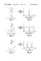
- FIGS. 1-6depict various illumination geometries that have been traditionally used in machine vision systems along with their associated incident angle brightness histograms.
- a coaxial illumination system 1is employed to illuminate an object 2 as it is viewed by an electronic machine vision camera 3 .
- this coaxial illumination systemprovides a uniform extended illumination zone 4 with a desirable incident illumination level that coincides with a zero angle of incidence off of the observation axis but is substantially devoid of any illumination as the angle of incidence deviates from zero.
- FIG. 3depicts an off-illumination axis diffuse dome lighting system 5 illuminating an object 2 to be observed by electronic machine vision camera 3 through an observation window 6 , which can be an opening or orifice or even a zone of material that appears transparent to a machine vision camera, such as clear plastic or the like.
- This illumination systemcreates the uniform diffuse illumination zone 4 shown in FIG. 4 . While the incident illumination level is substantially uniform as the angle of incidence of the light increases away from a zero angle of incidence off of the observation axis, the on-observation axis region 7 , which has an angle of incidence approaching zero degrees off-axis, is substantially devoid of any illumination.
- a conventional ring illumination system and its corresponding incident angle brightness histogramas depicted in FIGS. 5 and 6 respectively, provides a uniform diffuse illumination zone 4 with a substantially uniform incident illumination level that corresponds to substantially the same shape as the ring illuminator 8 being employed.
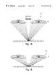
- FIGS. 7, 8 , 9 , and 10show four illumination systems and methods and their respective incident angle brightness histograms.
- FIG. 7shows a continuous diffuse illumination system that is comprised of a combination of the coaxial illumination system 1 of FIG. 1 and the off-illumination axis diffuse illumination system 5 of FIG. 3 .
- the combination of these two illumination componentsresults in a lighting environment with the incident angle brightness histogram shown in FIG. 8 .
- This environmentis characterized by a diffuse illumination zone 4 with a substantially uniform incident illumination level irrespective of the angle of incidence.
- FIGS. 11 and 12depict a side view and a bottom view, respectively, of a fresnel lens 12 .
- a conventional fresnel lensincludes a series of concentric grooves 12 , shaped onto a flat, thin piece of material.
- a fresnel lensmay be formed from a variety of light transmitting materials through conventional manufacturing techniques. For example, it may be molded from plastic or acrylic.
- the fresnel lens 10may be used to replace the curved surface of a conventional lens.
- the concentric grooves 12act as refracting surfaces, bending parallel rays to a common focus. Different fresnel lenses may have concentric grooves of different angles, so that lenses of a variety of focal lengths may be provided.
- a low-cost high-efficiency illumination method and apparatuswhich may be a method and apparatus for illuminating an object, wherein illumination of the object is by an illumination source, a partially reflective reflector, a reflecting cavity, and a fresnel lens.
- the methods and apparatusesmay include an electronic machine vision camera for receiving an image of an object and transmitting data corresponding to the image, an image processor, for receiving the data from the camera and generating data corresponding to the signal and a computer, for receiving, storing, manipulating and retrieving data from the image processor.
- the devicesmay include a housing having an inner reflective surface, an illumination source disposed in a ring on the inner reflective surface of the housing, a fresnel lens disposed on the housing opposite the inner reflective surface, for focusing illumination to the object, and a partially reflective reflector, disposed on the fresnel lens, for transmitting illumination to the object and for reflecting illumination to the inner reflective surface.
- the illumination sourcemay be a plurality of light emitting diodes disposed in a ring about the inner reflective surface, a ring light, or other illumination source.
- the partially reflective reflectormay be a half-silvered mirror.
- the devicesmay further include a camera for viewing the object, an image processor, for processing an image from the camera, and a processor, for storing, manipulating and retrieving data corresponding to the image.
- the processormay be part of a system for inventory management, materials handling, process control, or the like, or may be part of a machine vision device, such as a matrix code reader, robotic arm or hand held scanner.
- the fresnel lensmay be made interchangeable, so that lenses of different focal lengths may be used for viewing objects at different distances from the device.
- the devicemay include a circuit for controlling at least one of the color and the intensity of the illumination source.
- inventive concepts of the inventionmay be utilized in machine vision applications with objects having specular surfaces, including machined or molded surfaces of convex or concave configurations and surfaces containing numerous convex and concave texture elements such as those found in materials such as embossed metal foil, matte-finish photographs and the like.
- inventive concepts disclosed hereinare also applicable to film camera, video camera, digital camera and microscope-aided human inspection systems, to line-scanning image sensors and photocopiers, and to other applications where proper illumination is required in order to obtain acceptable image quality.
- the apparatus permitting the practice of the inventionis relatively simple and inexpensive as compared with prior art devices for providing continuous diffused illumination conditions.
- FIGS. 1 , 3 and 5depict traditional illumination geometries used in conjunction with machine vision systems, namely coaxial illumination, off-axis diffuse illumination, and ring illumination respectively;
- FIGS. 2 , 4 and 6depict incident angle brightness histograms, which are graphs plotting incident illumination level a function of angle of incidence, associated with the lighting geometries depicted in FIGS. 1, 3 and 5 respectively;
- FIGS. 7 and 9depict embodiments of continuous diffuse illumination geometries
- FIGS. 8 and 10depict the incident angle brightness histograms associated with the lighting geometries depicted in FIGS. 7 and 9 respectively;
- FIG. 11depicts a side view of a conventional fresnel lens
- FIG. 12depicts a front view of the fresnel lens of FIG. 11;
- FIG. 13depicts a side, cross-sectional view of an embodiment of a ring light of the present invention.
- FIG. 14depicts a bottom view of the embodiment of FIG. 13.
- FIGS. 15 and 16depicts side, cross-sectional views of embodiments having different focal lengths.
- FIG. 13depicts a side, cross-sectional view of components illustrating one embodiment of the inventive concepts, wherein the object 2 is to be observed under illumination by a device 20 .
- the object 2which, in the practice of the invention, could include a shiny or specular surface, such as the soldered surfaces of a printed circuit board, or a laser etched metal surface, reflective packaging surface, or the like, a dull surface, such as copy paper, a flat surface, such as paper, or an irregular or non-flat configuration, may be viewed by a camera 14 . The viewing of the object 2 may occur along the observation axis 16 as indicated in FIG. 13 . It should be understood that the device 20 may be provided without the camera 14 .
- the purpose of viewing the object 2 by the camera 14may be for any purpose requiring visual inspection, ranging from machine vision inspection, to reading of a matrix code, bar code or character string, to inspection for flaws. Observation may be for any desired reason, such as for purposes of orientation or assembly prior to subsequent machining operations, or reading or reproducing printed, inscribed or chemical- or laser- etched art work or print. Significant variations in the local intensity of light reflected from an uneven specular surface will result only from localized surface slope deviations from flatness greater than half the incident illumination angle with respect to the optical axis, such as are commonly associated with surface imperfections, and not from less severe normal deviations in surface geometry that are not associated with defect conditions.
- the device 20includes a housing 22 , which may be a molded plastic body or other housing capable of supporting the other elements of the invention described herein.
- the housing 22may have an inner reflective surface 24 .
- the inner reflective surface 24is a concave reflector cavity that reflects light off the concave surface along the general direction of the illumination axis 16 toward a surface on which the object 2 is disposed.
- the device 20may further include an illumination source 28 , which may be disposed on the housing 22 in a ring on the inner reflective surface 24 of the housing 10 .
- the illumination source 28is central to the inner reflective surface 24 and is disposed in a ring about the center of the device 20 .
- the illumination source 28may be a conventional illumination source, such as a ring light.
- the illumination source 28is a ring of light emitting diodes.
- the illumination source 28may be controlled by a circuit 30 , which is shown in block diagram format in FIG. 13, which may in turn be controlled by a processor 32 , also shown in block diagram format.
- the diodesmay be of different colors, and the processor 32 may control the color and intensity of the illumination coming from the illumination source 28 by controlling the individual diodes.
- the device 20may further include the fresnel lens 10 disposed on the housing 22 opposite the inner reflective surface 24 , for focusing illumination reflected to from the inner reflective surface 24 to the object 2 .
- the fresnel lens 10may be constructed from an expensive, light transmitting material, such as acrylic. If the device 20 is held close enough to the object 2 , light focused from the concentric grooves 12 of the fresnel lens 10 to the object 2 will arrive at a large solid angle of illumination, rendering continuous diffuse illumination conditions. That is, light will arrive from a variety of directions other than along the visual inspection axis 16 . The pitch of the fresnel lens 10 may be made fine enough that discontinuities in the illumination field will be effectively out of focus when reflected off the object 2 .
- the fresnel lens 10may include an aperture 38 disposed about the illumination axis 16 , which permits the camera 14 to view the object 2 along the illumination axis 16 .
- FIG. 14depicts a bottom view of the device 20 , in which the outer surface 34 of the fresnel lens 10 is seen.
- the fresnel lens 10includes the aperture 38 and the concentric grooves 12 .
- the device 20may include a partially reflective reflector 32 .
- the partially reflective reflector 32may be disposed on the fresnel lens 10 at a position opposite the illumination source 28 .
- the partially reflective reflector 32may thus be disposed along a concentric ring about the aperture 38 of the fresnel lens 10 , at a position approximately half of the distance of the radius of the fresnel lens 10 from the illumination axis 16 .
- the partially reflective reflector 32may be constructed to transmit part of the illumination from the illumination source 28 through the center of the fresnel lens 10 and to reflect another part of the illumination from the illumination source 28 back toward the inner reflective surface 24 .
- the illumination reflected back to the inner reflective surface 24may then be reflected back to the fresnel lens 10 for focusing on the object 2 .
- the partially reflective reflector 32scatters light from the point (in cross-section) or ring of the illumination source 28 at a wide range of angles onto the inner reflective surface 24 , which further scatters the light onto the fresnel lens 10 , permitting the fresnel lens 10 to produce a wide range of illumination angles of the object 2 , while using a small source.
- the high efficiency of transmission characteristic of fresnel lensespermits use of a small, cool, efficient illumination source, such as a light emitting diode.
- the partially reflective reflector 32may be formed as a half-silvered, convex, inner surface of the fresnel lens 10 . That is, a center portion of the fresnel lens 10 may be partially silvered, so that the center portion reflects a divergent light bundle back to the inner reflective surface 24 , while transmitting some fight through to the object 2 . The divergent fight bundle is then reflected back off the inner reflective surface 24 through the fresnel lens 10 , to the object 2 . The light that passes through the half-silvered partially reflective reflector 32 of the fresnel lens 10 emerges through a convex outer lens surface 34 of the center of the fresnel lens 10 and is focused on the object being observed.
- the density profile of the partially reflective reflector 32may be designed to cause the transmitted fight to match in intensity the average intensity from the fresnel lens 10 .
- the resultis a large solid angle of incident illumination where a high percentage of the output of the LEDs is focused on the object being observed.
- the device 20may have an efficiency sufficient to permit the light to be effectively strobed.
- the camera 14may be a machine vision camera, for producing an image corresponding to the object.
- the device 20may farther include the processor 32 .
- the processor 32may control the circuit 30 for controlling the illumination source 28 .
- the circuit 30may be used to control white light emitting diodes to alter the intensity of the illumination from the device 20 , either globally, or in discrete segments of the illumination source 28 . If color light emitting diodes are used as the illumination source, then the circuit 30 may be used to control the color of light from the device 20 . In embodiments, high intensity red light emitting diodes, or alternating red, green and blue light emitting diodes may be used.
- the processor 32may further process the image from the camera 14 to generate data.
- the processor 32may be included in the housing 22 , it may be an external processor 32 , or the processor 32 may be understood to encompass one or more different processors located in the housing 22 , external to the housing 22 , or both. Part of the processor 32 may process the data from the camera 14 .
- the processor 32may be part of a system for storage, manipulation, or retrieval of image data, such as an inventory management system, a materials handling system, or a process control system.
- the data from the device 20may be transmitted, via a connector, or by other transmission mechanisms, such as infrared, radio, or other mechanism, to an external computer or computers which may be part of other systems and apparatuses that are responsive to image data.
- Such systemscan include process control systems, manufacturing systems, inventory management systems, material handling systems, robotic arms, or any other robotic or machine vision systems.
- the device 20may be integrated into any other device that is responsive to imaging data.
- the device 20may similarly be any device that includes an image processor, such as a hand held scanner, a matrix code reader, or a semiconductor manufacturing device.
- a fresnel lens 10Since a fresnel lens 10 has a single focal length, satisfactory illumination conditions (continuous diffuse illumination conditions) will be produced by the device only in a particular range of distances from the device 20 . Accordingly, referring to FIGS. 15 and 16, the fresnel lens 10 may be made removable, so that the fresnel lens 10 is interchangeable with another lens. Thus, as depicted in FIG. 15 and FIG. 16, the device 20 may be provided with different focal lengths of fresnel lens 10 , meaning that the device 20 can be used to view an object 2 at different distances from the device 20 with a large solid angle of illumination.
- a primary fresnel lens 10provides a focal length sufficient to provide continuous diffuse illumination conditions if the device 20 is positioned about four inches from the object 2 , and alternate lenses may be provided for different distances.
- the housing 22may be formed of molded plastic, with the fresnel lens 22 being made of acrylic.
- the devicemay be made extremely rugged, easy to assemble, easy to manufacture and easy to maintain.
- a ring of light emitting diodes, if used as the illumination source 28would be easy to replace.
- a fancould be disposed on the housing 22 to cool the device 22 , if desired.
- Methods of image processing encompassed hereininclude providing a ring of light emitting diodes as the illumination source 28 , reflecting light from the illumination source 28 with the partially reflective reflector 32 to the internal reflective surface 24 and focusing illumination reflected from the internal reflective surface 24 with the fresnel lens 10 to the object 2 .
- Methods disclosed hereinfurther include providing the camera 14 for producing an image of the object, and providing a processor for controlling the illumination source 28 and for storing, manipulating and retrieving data from the camera 14 .
Landscapes
- Engineering & Computer Science (AREA)
- Multimedia (AREA)
- Signal Processing (AREA)
- Physics & Mathematics (AREA)
- Health & Medical Sciences (AREA)
- Life Sciences & Earth Sciences (AREA)
- Chemical & Material Sciences (AREA)
- Analytical Chemistry (AREA)
- Biochemistry (AREA)
- General Health & Medical Sciences (AREA)
- General Physics & Mathematics (AREA)
- Immunology (AREA)
- Pathology (AREA)
- Investigating Materials By The Use Of Optical Means Adapted For Particular Applications (AREA)
Abstract
Description
The invention pertains to the field of illumination, and in particular to methods and systems for providing a large solid angle of high intensity illumination of an observed object.
Electronic machine vision apparatuses are commonly employed in conjunction with automatic manufacturing, machining, assembly and inspection apparatuses, particularly of the robotics type. Observing apparatuses, such as television cameras, are commonly employed to observe the object being machined, assembled, or inspected, and the image received and signal transmitted by the camera can be compared to a standard image or signal stored in a database to determine if the observed article is properly machined, oriented, or assembled. Also, machine vision is widely used in inspection and flaw detection applications whereby inconsistencies and imperfection in both hard and soft goods can be rapidly ascertained and adjustments or rejections instantaneously effected.
When the object being observed has a shiny specular surface, reflections of non-uniformities in the local lighting environment may create misleading visual features that interfere with the accuracy of the inspection task such as the appearance of a reflected shadow on a laser etched letter “I” causing it to appear to the machine vision apparatus as the letter “T”. In the inspection of soldered circuits such as those used with printed circuit boards, the highly reflective nature and uneven surface geometry of the solder makes it very difficult to obtain an accurate electronic signal, and the same is true when machine vision is used to inspect laser etched metal surfaces, reflective packaging, and other objects having shiny surfaces, particularly irregular shiny surfaces.
In order to view a mark, image contrast is necessary between the mark and the underlying material. Specular surfaces require a specific illumination geometry to achieve the required image contrast for the features of interest, which is determined by the angle of viewing and the surface's geometry relative to the optical axis between the surface and the viewer. For normal viewing of a flat specular surface, i.e., a surface in which the optical axis is perpendicular to the surface being imaged and the surface is substantially a plane, the light source must have a width equal to at least twice the size of the object field of view plus the diameter of the camera aperture for a normal lens if the light source is integrated with the camera. This relationship is independent of distance from the light source to the surface being observed.
Uneven specular surfaces require a large solid angle of uniform illumination to appear uniformly illuminated, depending on the degree of surface unevenness. A large solid angle of illumination is characterized by light striking the surface to be viewed over a large continuous range of incident angles. A solid angle of front illumination of 160° allows a specular surface with approximately +/−40° of unevenness to appear uniformly illuminated.
Illumination systems exist that produce illumination that is continuous and uniform in nature and is free of dark, bright or void portions capable of generating erroneous vision signals. Examples of such systems are disclosed in U.S. Pat. Nos. 5,684,530 and 5,461,417, each of which discloses a continuous diffuse illumination (“CDI”) method and apparatus. The disclosure of each of such U.S. Patents is incorporated by reference herein. CDI illumination provides dramatically improved results when machine vision is used to view shiny, irregular objects.
FIGS. 1-6 depict various illumination geometries that have been traditionally used in machine vision systems along with their associated incident angle brightness histograms. For example, in FIG. 1, acoaxial illumination system 1 is employed to illuminate anobject 2 as it is viewed by an electronicmachine vision camera 3. As can be seen from the incident angle brightness histogram shown in FIG. 2, this coaxial illumination system provides a uniform extendedillumination zone 4 with a desirable incident illumination level that coincides with a zero angle of incidence off of the observation axis but is substantially devoid of any illumination as the angle of incidence deviates from zero.
FIG. 3 depicts an off-illumination axis diffusedome lighting system 5 illuminating anobject 2 to be observed by electronicmachine vision camera 3 through anobservation window 6, which can be an opening or orifice or even a zone of material that appears transparent to a machine vision camera, such as clear plastic or the like. This illumination system creates the uniformdiffuse illumination zone 4 shown in FIG.4. While the incident illumination level is substantially uniform as the angle of incidence of the light increases away from a zero angle of incidence off of the observation axis, the on-observation axis region 7, which has an angle of incidence approaching zero degrees off-axis, is substantially devoid of any illumination.
A conventional ring illumination system and its corresponding incident angle brightness histogram, as depicted in FIGS. 5 and 6 respectively, provides a uniformdiffuse illumination zone 4 with a substantially uniform incident illumination level that corresponds to substantially the same shape as thering illuminator 8 being employed.
FIGS. 7,8,9, and10 show four illumination systems and methods and their respective incident angle brightness histograms. First, FIG. 7 shows a continuous diffuse illumination system that is comprised of a combination of thecoaxial illumination system 1 of FIG.1 and the off-illumination axisdiffuse illumination system 5 of FIG.3. The combination of these two illumination components results in a lighting environment with the incident angle brightness histogram shown in FIG.8. This environment is characterized by adiffuse illumination zone 4 with a substantially uniform incident illumination level irrespective of the angle of incidence.
When utilizing machine vision techniques, it is common to employ complicated fighting systems for illumination the object being observed. Some such systems eliminate shadows, highlights, reflections and other lighting characteristics caused by shiny convex surface objects. Other systems provide increased contrast to images printed on dull, flat surfaces. Examples of complex lighting systems for use with machine vision apparatus are shown in U.S. Pat. Nos. 4,677,473; 4,882,498; 5,051,825; 5,060,065 and 5,072,127. The disclosure of such patents is incorporated by reference herein. The devices shown in these patents are capable of generating improved lighting characteristics. However, such devices may in some instances be too complex or expensive to manufacture relative to the benefit they provide. Also, some devices may require a relatively intense, illumination source. Accordingly, a simple to manufacture device that provides adequate illumination of uneven specular surfaces at high-efficiency is desirable.
FIGS. 11 and 12 depict a side view and a bottom view, respectively, of afresnel lens 12. A conventional fresnel lens includes a series ofconcentric grooves 12, shaped onto a flat, thin piece of material. A fresnel lens may be formed from a variety of light transmitting materials through conventional manufacturing techniques. For example, it may be molded from plastic or acrylic. Thefresnel lens 10 may be used to replace the curved surface of a conventional lens. Theconcentric grooves 12 act as refracting surfaces, bending parallel rays to a common focus. Different fresnel lenses may have concentric grooves of different angles, so that lenses of a variety of focal lengths may be provided.
Provided herein is a low-cost high-efficiency illumination method and apparatus, which may be a method and apparatus for illuminating an object, wherein illumination of the object is by an illumination source, a partially reflective reflector, a reflecting cavity, and a fresnel lens. The methods and apparatuses may include an electronic machine vision camera for receiving an image of an object and transmitting data corresponding to the image, an image processor, for receiving the data from the camera and generating data corresponding to the signal and a computer, for receiving, storing, manipulating and retrieving data from the image processor.
Provided herein are devices and methods of illuminating an object. The devices may include a housing having an inner reflective surface, an illumination source disposed in a ring on the inner reflective surface of the housing, a fresnel lens disposed on the housing opposite the inner reflective surface, for focusing illumination to the object, and a partially reflective reflector, disposed on the fresnel lens, for transmitting illumination to the object and for reflecting illumination to the inner reflective surface. The illumination source may be a plurality of light emitting diodes disposed in a ring about the inner reflective surface, a ring light, or other illumination source. The partially reflective reflector may be a half-silvered mirror. The devices may further include a camera for viewing the object, an image processor, for processing an image from the camera, and a processor, for storing, manipulating and retrieving data corresponding to the image. The processor may be part of a system for inventory management, materials handling, process control, or the like, or may be part of a machine vision device, such as a matrix code reader, robotic arm or hand held scanner. The fresnel lens may be made interchangeable, so that lenses of different focal lengths may be used for viewing objects at different distances from the device. The device may include a circuit for controlling at least one of the color and the intensity of the illumination source.
The practice of the concepts of the invention may be utilized in machine vision applications with objects having specular surfaces, including machined or molded surfaces of convex or concave configurations and surfaces containing numerous convex and concave texture elements such as those found in materials such as embossed metal foil, matte-finish photographs and the like. However, it will be appreciated that the inventive concepts disclosed herein are also applicable to film camera, video camera, digital camera and microscope-aided human inspection systems, to line-scanning image sensors and photocopiers, and to other applications where proper illumination is required in order to obtain acceptable image quality.
As will be appreciated from the following description, the apparatus permitting the practice of the invention is relatively simple and inexpensive as compared with prior art devices for providing continuous diffused illumination conditions.
The aforementioned objects and advantages of the invention will be appreciated from the following description and accompanying drawings wherein:
FIGS.1,3 and5 depict traditional illumination geometries used in conjunction with machine vision systems, namely coaxial illumination, off-axis diffuse illumination, and ring illumination respectively;
FIGS.2,4 and6 depict incident angle brightness histograms, which are graphs plotting incident illumination level a function of angle of incidence, associated with the lighting geometries depicted in FIGS. 1,3 and5 respectively;
FIGS. 7 and 9 depict embodiments of continuous diffuse illumination geometries;
FIGS. 8 and 10 depict the incident angle brightness histograms associated with the lighting geometries depicted in FIGS. 7 and 9 respectively;
FIG. 11 depicts a side view of a conventional fresnel lens;
FIG. 12 depicts a front view of the fresnel lens of FIG. 11;
FIG. 13 depicts a side, cross-sectional view of an embodiment of a ring light of the present invention;
FIG. 14 depicts a bottom view of the embodiment of FIG. 13; and
FIGS. 15 and 16 depicts side, cross-sectional views of embodiments having different focal lengths.
FIG. 13 depicts a side, cross-sectional view of components illustrating one embodiment of the inventive concepts, wherein theobject 2 is to be observed under illumination by adevice 20. In an embodiment of the invention, theobject 2, which, in the practice of the invention, could include a shiny or specular surface, such as the soldered surfaces of a printed circuit board, or a laser etched metal surface, reflective packaging surface, or the like, a dull surface, such as copy paper, a flat surface, such as paper, or an irregular or non-flat configuration, may be viewed by acamera 14. The viewing of theobject 2 may occur along theobservation axis 16 as indicated in FIG.13. It should be understood that thedevice 20 may be provided without thecamera 14.
The purpose of viewing theobject 2 by thecamera 14 may be for any purpose requiring visual inspection, ranging from machine vision inspection, to reading of a matrix code, bar code or character string, to inspection for flaws. Observation may be for any desired reason, such as for purposes of orientation or assembly prior to subsequent machining operations, or reading or reproducing printed, inscribed or chemical- or laser- etched art work or print. Significant variations in the local intensity of light reflected from an uneven specular surface will result only from localized surface slope deviations from flatness greater than half the incident illumination angle with respect to the optical axis, such as are commonly associated with surface imperfections, and not from less severe normal deviations in surface geometry that are not associated with defect conditions.
In the embodiment of the invention depicted in FIG. 13, thedevice 20 includes ahousing 22, which may be a molded plastic body or other housing capable of supporting the other elements of the invention described herein. Thehousing 22 may have an innerreflective surface 24. In an embodiment of the invention, the innerreflective surface 24 is a concave reflector cavity that reflects light off the concave surface along the general direction of theillumination axis 16 toward a surface on which theobject 2 is disposed.
Thedevice 20 may further include anillumination source 28, which may be disposed on thehousing 22 in a ring on the innerreflective surface 24 of thehousing 10. In an embodiment, theillumination source 28 is central to the innerreflective surface 24 and is disposed in a ring about the center of thedevice 20. Theillumination source 28 may be a conventional illumination source, such as a ring light. In an embodiment, theillumination source 28 is a ring of light emitting diodes. Theillumination source 28 may be controlled by acircuit 30, which is shown in block diagram format in FIG. 13, which may in turn be controlled by aprocessor 32, also shown in block diagram format. In an embodiment of the invention in which the illumination source is a ring of light emitting diodes, the diodes may be of different colors, and theprocessor 32 may control the color and intensity of the illumination coming from theillumination source 28 by controlling the individual diodes.
Thedevice 20 may further include thefresnel lens 10 disposed on thehousing 22 opposite the innerreflective surface 24, for focusing illumination reflected to from the innerreflective surface 24 to theobject 2. Thefresnel lens 10 may be constructed from an expensive, light transmitting material, such as acrylic. If thedevice 20 is held close enough to theobject 2, light focused from theconcentric grooves 12 of thefresnel lens 10 to theobject 2 will arrive at a large solid angle of illumination, rendering continuous diffuse illumination conditions. That is, light will arrive from a variety of directions other than along thevisual inspection axis 16. The pitch of thefresnel lens 10 may be made fine enough that discontinuities in the illumination field will be effectively out of focus when reflected off theobject 2. Thefresnel lens 10 may include anaperture 38 disposed about theillumination axis 16, which permits thecamera 14 to view theobject 2 along theillumination axis 16.
FIG. 14 depicts a bottom view of thedevice 20, in which theouter surface 34 of thefresnel lens 10 is seen. Thefresnel lens 10 includes theaperture 38 and theconcentric grooves 12.
Referring to FIGS. 13 and 14, thedevice 20 may include a partiallyreflective reflector 32. Referring to FIG. 13, in an embodiment, the partiallyreflective reflector 32 may be disposed on thefresnel lens 10 at a position opposite theillumination source 28. Referring to FIG. 14, the partiallyreflective reflector 32 may thus be disposed along a concentric ring about theaperture 38 of thefresnel lens 10, at a position approximately half of the distance of the radius of thefresnel lens 10 from theillumination axis 16. Referring again to FIG. 13, the partiallyreflective reflector 32 may be constructed to transmit part of the illumination from theillumination source 28 through the center of thefresnel lens 10 and to reflect another part of the illumination from theillumination source 28 back toward the innerreflective surface 24. The illumination reflected back to the innerreflective surface 24 may then be reflected back to thefresnel lens 10 for focusing on theobject 2. Thus, the partiallyreflective reflector 32 scatters light from the point (in cross-section) or ring of theillumination source 28 at a wide range of angles onto the innerreflective surface 24, which further scatters the light onto thefresnel lens 10, permitting thefresnel lens 10 to produce a wide range of illumination angles of theobject 2, while using a small source. The high efficiency of transmission characteristic of fresnel lenses permits use of a small, cool, efficient illumination source, such as a light emitting diode.
The partiallyreflective reflector 32 may be formed as a half-silvered, convex, inner surface of thefresnel lens 10. That is, a center portion of thefresnel lens 10 may be partially silvered, so that the center portion reflects a divergent light bundle back to the innerreflective surface 24, while transmitting some fight through to theobject 2. The divergent fight bundle is then reflected back off the innerreflective surface 24 through thefresnel lens 10, to theobject 2. The light that passes through the half-silvered partiallyreflective reflector 32 of thefresnel lens 10 emerges through a convexouter lens surface 34 of the center of thefresnel lens 10 and is focused on the object being observed. The density profile of the partiallyreflective reflector 32 may be designed to cause the transmitted fight to match in intensity the average intensity from thefresnel lens 10. The result is a large solid angle of incident illumination where a high percentage of the output of the LEDs is focused on the object being observed. In an embodiment, thedevice 20 may have an efficiency sufficient to permit the light to be effectively strobed.
Thecamera 14 may be a machine vision camera, for producing an image corresponding to the object. Thedevice 20 may farther include theprocessor 32. Theprocessor 32 may control thecircuit 30 for controlling theillumination source 28. In an embodiment of the invention, thecircuit 30 may be used to control white light emitting diodes to alter the intensity of the illumination from thedevice 20, either globally, or in discrete segments of theillumination source 28. If color light emitting diodes are used as the illumination source, then thecircuit 30 may be used to control the color of light from thedevice 20. In embodiments, high intensity red light emitting diodes, or alternating red, green and blue light emitting diodes may be used.
Theprocessor 32 may further process the image from thecamera 14 to generate data. Theprocessor 32 may be included in thehousing 22, it may be anexternal processor 32, or theprocessor 32 may be understood to encompass one or more different processors located in thehousing 22, external to thehousing 22, or both. Part of theprocessor 32 may process the data from thecamera 14. Thus, theprocessor 32 may be part of a system for storage, manipulation, or retrieval of image data, such as an inventory management system, a materials handling system, or a process control system. Thus, the data from thedevice 20 may be transmitted, via a connector, or by other transmission mechanisms, such as infrared, radio, or other mechanism, to an external computer or computers which may be part of other systems and apparatuses that are responsive to image data. Such systems can include process control systems, manufacturing systems, inventory management systems, material handling systems, robotic arms, or any other robotic or machine vision systems. Thus, thedevice 20 may be integrated into any other device that is responsive to imaging data. Thedevice 20 may similarly be any device that includes an image processor, such as a hand held scanner, a matrix code reader, or a semiconductor manufacturing device.
Since afresnel lens 10 has a single focal length, satisfactory illumination conditions (continuous diffuse illumination conditions) will be produced by the device only in a particular range of distances from thedevice 20. Accordingly, referring to FIGS. 15 and 16, thefresnel lens 10 may be made removable, so that thefresnel lens 10 is interchangeable with another lens. Thus, as depicted in FIG.15 and FIG. 16, thedevice 20 may be provided with different focal lengths offresnel lens 10, meaning that thedevice 20 can be used to view anobject 2 at different distances from thedevice 20 with a large solid angle of illumination. In an embodiment of the invention, aprimary fresnel lens 10 provides a focal length sufficient to provide continuous diffuse illumination conditions if thedevice 20 is positioned about four inches from theobject 2, and alternate lenses may be provided for different distances.
Thehousing 22 may be formed of molded plastic, with thefresnel lens 22 being made of acrylic. Thus, the device may be made extremely rugged, easy to assemble, easy to manufacture and easy to maintain. A ring of light emitting diodes, if used as theillumination source 28, would be easy to replace. A fan could be disposed on thehousing 22 to cool thedevice 22, if desired.
Methods of image processing encompassed herein include providing a ring of light emitting diodes as theillumination source 28, reflecting light from theillumination source 28 with the partiallyreflective reflector 32 to the internalreflective surface 24 and focusing illumination reflected from the internalreflective surface 24 with thefresnel lens 10 to theobject 2. Methods disclosed herein further include providing thecamera 14 for producing an image of the object, and providing a processor for controlling theillumination source 28 and for storing, manipulating and retrieving data from thecamera 14.
Since certain changes may be made in the above described illumination device, without departing from the spirit and scope of the invention herein involved, it is intended that all of the subject matter of the above description or shown in the accompanying drawings shall be interpreted merely as illustrative examples and shall not be construed as limiting the invention.
Claims (34)
1. A device for illuminating an object, comprising:
a housing having an inner reflective surface;
an illumination source, disposed in a ring on the inner reflective surface;
a fresnel lens disposed on the housing opposite the inner reflective surface, for focusing illumination to the object; and
a partially reflective reflector, disposed on the fresnel lens, for transmitting illumination to the object and for reflecting illumination to the inner reflective surface.
2. The device of claim1, wherein the illumination source is a plurality of light emitting diodes.
3. The device of claim1, wherein the illumination source is a ring light.
4. The device of claim1, wherein the partially reflective reflector is a half-silvered mirror.
5. The device of claim1, wherein the housing includes an aperture, further comprising:
a camera for viewing the object.
6. The device of claim5, wherein the camera is a machine vision camera for producing an image corresponding to the object.
7. The device of claim6, further comprising:
a processor, for processing the image to generate data.
8. The device of claim7, further comprising:
an inventory management system for processing the data.
9. The device of claim7, further comprising:
a materials handling system for processing the data.
10. The device of claim7, further comprising:
a matrix code reader for processing the data.
11. The device of claim7, further comprising:
a process control system for processing the data.
12. The device of claim7, further comprising:
a hand held scanner for processing the data.
13. The device of claim1, wherein the fresnel lens is removable, so that the fresnel lens is interchangeable with another lens.
14. The device of claim1, further comprising:
a circuit for controlling at least one of the color and the intensity of the illumination source.
15. The device of claim14, wherein the illumination source is a ring of light emitting diodes of a plurality of different colors.
16. The device of claim1, further comprising:
a fan for cooling the device.
17. A method of image processing an image from an illuminated object, comprising:
providing a ring of light emitting diodes;
providing a partially reflective reflector;
providing a fresnel lens for focusing illumination on the object;
providing a camera for viewing the object;
providing a vision processor for processing data from the camera; and
providing a computer for storing manipulating and retrieving data from the vision processor.
18. The method of claim16, wherein the computer controls a process based on the data.
19. The method of claim17, wherein the process is a manufacturing process.
20. The method of claim17, wherein the process is an inventory control process.
21. The method of claim17, wherein the process is a materials handling process.
22. A method of illuminating an object, comprising:
providing an illumination source;
providing a fresnel lens for focusing illumination on the object;
providing a partially reflective reflector, disposed on the fresnel lens, for transmitting illumination to the object and for reflecting illumination to the inner reflective surface; and
providing a reflective surface, for reflecting illumination from the partially reflective reflector to the fresnel lens.
23. The method of claim22, wherein the illumination source is a plurality of light emitting diodes.
24. The method of claim22, wherein the illumination source is a ring light.
25. The method of claim22, wherein the partially reflective reflector is a half-silvered mirror.
26. The method of claim22, further comprising:
providing a camera for viewing the object.
27. The method of claim26, wherein the camera is a machine vision camera for producing an image corresponding to the object.
28. The method of claim27, further comprising:
processing the image to generate data.
29. The method of claim28, further comprising:
providing an inventory management system for processing the data.
30. The method of claim28, further comprising:
providing a materials handling system for processing the data.
31. The method of claim28, further comprising:
providing a matrix code reader for processing the data.
32. The method of claim28, further comprising:
providing a process control system for processing the data.
33. The method of claim22, wherein the fresnel lens is removable, so that the fresnel lens is interchangeable with another lens.
34. The method of claim22, further comprising:
controlling at least one of the color and the intensity of the illumination source.
Priority Applications (1)
| Application Number | Priority Date | Filing Date | Title |
|---|---|---|---|
| US09/158,735US6273338B1 (en) | 1998-09-22 | 1998-09-22 | Low cost color-programmable focusing ring light |
Applications Claiming Priority (1)
| Application Number | Priority Date | Filing Date | Title |
|---|---|---|---|
| US09/158,735US6273338B1 (en) | 1998-09-22 | 1998-09-22 | Low cost color-programmable focusing ring light |
Publications (1)
| Publication Number | Publication Date |
|---|---|
| US6273338B1true US6273338B1 (en) | 2001-08-14 |
Family
ID=22569458
Family Applications (1)
| Application Number | Title | Priority Date | Filing Date |
|---|---|---|---|
| US09/158,735Expired - Fee RelatedUS6273338B1 (en) | 1998-09-22 | 1998-09-22 | Low cost color-programmable focusing ring light |
Country Status (1)
| Country | Link |
|---|---|
| US (1) | US6273338B1 (en) |
Cited By (125)
| Publication number | Priority date | Publication date | Assignee | Title |
|---|---|---|---|---|
| US20020114505A1 (en)* | 1999-10-18 | 2002-08-22 | James Mahon | Machine vision |
| US20030067774A1 (en)* | 2001-10-04 | 2003-04-10 | Nanovia, L.P. | Illumination systems and methods employing diffractive holographic optical elements |
| US20030076281A1 (en)* | 1997-08-26 | 2003-04-24 | Frederick Marshall Morgan | Diffuse illumination systems and methods |
| US20040032653A1 (en)* | 2002-08-16 | 2004-02-19 | Gohman Jeffrey Alan | Wide angle lens system having a distorted intermediate image |
| US20040047037A1 (en)* | 2002-08-16 | 2004-03-11 | Peterson Mark David | Rear projection display |
| US6717376B2 (en) | 1997-08-26 | 2004-04-06 | Color Kinetics, Incorporated | Automotive information systems |
| US20040114035A1 (en)* | 1998-03-24 | 2004-06-17 | Timothy White | Focusing panel illumination method and apparatus |
| US6777891B2 (en) | 1997-08-26 | 2004-08-17 | Color Kinetics, Incorporated | Methods and apparatus for controlling devices in a networked lighting system |
| US20040184032A1 (en)* | 2003-03-20 | 2004-09-23 | James Mahon | Optical inspection system and method for displaying imaged objects in greater than two dimensions |
| US20040184653A1 (en)* | 2003-03-20 | 2004-09-23 | Baer Richard L. | Optical inspection system, illumination apparatus and method for use in imaging specular objects based on illumination gradients |
| US20040184648A1 (en)* | 2003-03-20 | 2004-09-23 | Xuemei Zhang | System and method for shape reconstruction from optical images |
| US20040184031A1 (en)* | 2003-03-20 | 2004-09-23 | Vook Dietrich W. | Optical inspection system, apparatus and method for reconstructing three-dimensional images for printed circuit board and electronics manufacturing inspection |
| US20040212881A1 (en)* | 2002-08-16 | 2004-10-28 | Mark Peterson | Laminate screen for display device |
| US20040218268A1 (en)* | 2002-08-16 | 2004-11-04 | Peterson Mark D. | Rear projection display |
| US20040223123A1 (en)* | 2002-08-16 | 2004-11-11 | Engle T. Scott | Projection device and screen |
| US20040227990A1 (en)* | 2002-08-16 | 2004-11-18 | Peterson Mark D. | Variable fresnel screen for use in projection device |
| US20040233394A1 (en)* | 2002-08-16 | 2004-11-25 | Gohman Jeffrey A. | Wide angle projection lens |
| US20040257539A1 (en)* | 2002-08-16 | 2004-12-23 | Peterson Mark D. | Projection television device and screen |
| US6897624B2 (en) | 1997-08-26 | 2005-05-24 | Color Kinetics, Incorporated | Packaged information systems |
| US20050146687A1 (en)* | 2004-01-06 | 2005-07-07 | Gohman Jeffrey A. | Fresnel lens having reduced distortions |
| WO2005048169A3 (en)* | 2003-11-14 | 2005-07-14 | Sick Auto Ident Inc | Scanning imaging system and method for imaging articles using same |
| US20050185270A1 (en)* | 2004-02-25 | 2005-08-25 | Scott Engle | Environmentally-adaptive frame assembly |
| US6965205B2 (en) | 1997-08-26 | 2005-11-15 | Color Kinetics Incorporated | Light emitting diode based products |
| US6975079B2 (en) | 1997-08-26 | 2005-12-13 | Color Kinetics Incorporated | Systems and methods for controlling illumination sources |
| US20060000989A1 (en)* | 2004-06-30 | 2006-01-05 | Omron Corporation | Method of generating image and illumination device for inspecting substrate |
| US20060028623A1 (en)* | 2003-08-19 | 2006-02-09 | Engle Timothy S | Method and system for a thermal architecture and user adjustable keystone in a display device |
| US20060051086A1 (en)* | 2002-11-23 | 2006-03-09 | Michael Schroter | Method for photographically recording a cylindrical, especially plate-shaped object |
| US7038399B2 (en) | 2001-03-13 | 2006-05-02 | Color Kinetics Incorporated | Methods and apparatus for providing power to lighting devices |
| US20060091333A1 (en)* | 2002-06-21 | 2006-05-04 | Cochran Don W | Patterned illumination method and apparatus for machine vision systems |
| US20060091825A1 (en)* | 2004-11-01 | 2006-05-04 | Gil Abramovich | Reconfigurable linescan illumination |
| US20060091214A1 (en)* | 2004-11-02 | 2006-05-04 | The Code Corporation | Graphical code reading apparatus for reading codes on reflective surfaces |
| US7042172B2 (en) | 2000-09-01 | 2006-05-09 | Color Kinetics Incorporated | Systems and methods for providing illumination in machine vision systems |
| US7064498B2 (en) | 1997-08-26 | 2006-06-20 | Color Kinetics Incorporated | Light-emitting diode based products |
| US7102820B2 (en) | 2002-08-16 | 2006-09-05 | Infocus Corporation | Flat valley fresnel lens for a display device |
| US20060228017A1 (en)* | 2003-06-12 | 2006-10-12 | Yukio Kuramasu | Impurity measuring method and device |
| US7161311B2 (en) | 1997-08-26 | 2007-01-09 | Color Kinetics Incorporated | Multicolored LED lighting method and apparatus |
| US20070014005A1 (en)* | 2002-08-16 | 2007-01-18 | Infocus Corporation | Laminate screen for a display device |
| US7178941B2 (en) | 2003-05-05 | 2007-02-20 | Color Kinetics Incorporated | Lighting methods and systems |
| US7186003B2 (en) | 1997-08-26 | 2007-03-06 | Color Kinetics Incorporated | Light-emitting diode based products |
| US20070051883A1 (en)* | 2003-06-23 | 2007-03-08 | Advanced Optical Technologies, Llc | Lighting using solid state light sources |
| US7202613B2 (en) | 2001-05-30 | 2007-04-10 | Color Kinetics Incorporated | Controlled lighting methods and apparatus |
| US7221104B2 (en) | 1997-08-26 | 2007-05-22 | Color Kinetics Incorporated | Linear lighting apparatus and methods |
| US7231060B2 (en) | 1997-08-26 | 2007-06-12 | Color Kinetics Incorporated | Systems and methods of generating control signals |
| US7242152B2 (en) | 1997-08-26 | 2007-07-10 | Color Kinetics Incorporated | Systems and methods of controlling light systems |
| US20070205285A1 (en)* | 2006-03-06 | 2007-09-06 | Tan Cheng W | Reflective encoder with interchangable lens on emitter-detector module |
| US7300192B2 (en) | 2002-10-03 | 2007-11-27 | Color Kinetics Incorporated | Methods and apparatus for illuminating environments |
| US7303300B2 (en) | 2000-09-27 | 2007-12-04 | Color Kinetics Incorporated | Methods and systems for illuminating household products |
| US7309965B2 (en) | 1997-08-26 | 2007-12-18 | Color Kinetics Incorporated | Universal lighting network methods and systems |
| US20080030343A1 (en)* | 2006-07-31 | 2008-02-07 | Raybuck John L | RFID ring illumination system for surgical machine |
| US7344273B2 (en) | 2005-03-22 | 2008-03-18 | Binary Works, Inc. | Ring light with user manipulable control |
| US7358679B2 (en) | 2002-05-09 | 2008-04-15 | Philips Solid-State Lighting Solutions, Inc. | Dimmable LED-based MR16 lighting apparatus and methods |
| US7385359B2 (en) | 1997-08-26 | 2008-06-10 | Philips Solid-State Lighting Solutions, Inc. | Information systems |
| US7453217B2 (en) | 1997-08-26 | 2008-11-18 | Philips Solid-State Lighting Solutions, Inc. | Marketplace illumination methods and apparatus |
| US20090121838A1 (en)* | 2006-07-21 | 2009-05-14 | Mezhinsky Victor B | Smart Connector System For Surgical Machine |
| US7572028B2 (en) | 1999-11-18 | 2009-08-11 | Philips Solid-State Lighting Solutions, Inc. | Methods and apparatus for generating and modulating white light illumination conditions |
| US7598681B2 (en) | 2001-05-30 | 2009-10-06 | Philips Solid-State Lighting Solutions, Inc. | Methods and apparatus for controlling devices in a networked lighting system |
| US7598686B2 (en) | 1997-12-17 | 2009-10-06 | Philips Solid-State Lighting Solutions, Inc. | Organic light emitting diode methods and apparatus |
| EP1865308A3 (en)* | 2006-06-07 | 2009-12-09 | Microscan Systems, Inc. | System for providing monochromatic light |
| US7642730B2 (en) | 2000-04-24 | 2010-01-05 | Philips Solid-State Lighting Solutions, Inc. | Methods and apparatus for conveying information via color of light |
| US7659674B2 (en) | 1997-08-26 | 2010-02-09 | Philips Solid-State Lighting Solutions, Inc. | Wireless lighting control methods and apparatus |
| US20100128165A1 (en)* | 2008-11-26 | 2010-05-27 | David Newcomb | System and method for acquiring images |
| US7845823B2 (en) | 1997-08-26 | 2010-12-07 | Philips Solid-State Lighting Solutions, Inc. | Controlled lighting methods and apparatus |
| US7926975B2 (en) | 2007-12-21 | 2011-04-19 | Altair Engineering, Inc. | Light distribution using a light emitting diode assembly |
| EP1548396A4 (en)* | 2002-08-08 | 2011-05-04 | Panasonic Corp | LIGHTING DEVICE, RECOGNITION DEVICE HAVING THE LIGHTING DEVICE, AND PART MOUNTING DEVICE |
| US7938562B2 (en) | 2008-10-24 | 2011-05-10 | Altair Engineering, Inc. | Lighting including integral communication apparatus |
| US7946729B2 (en) | 2008-07-31 | 2011-05-24 | Altair Engineering, Inc. | Fluorescent tube replacement having longitudinally oriented LEDs |
| US7976196B2 (en) | 2008-07-09 | 2011-07-12 | Altair Engineering, Inc. | Method of forming LED-based light and resulting LED-based light |
| US8011905B2 (en) | 2005-11-17 | 2011-09-06 | Novartis Ag | Surgical cassette |
| US8118447B2 (en) | 2007-12-20 | 2012-02-21 | Altair Engineering, Inc. | LED lighting apparatus with swivel connection |
| US8214084B2 (en) | 2008-10-24 | 2012-07-03 | Ilumisys, Inc. | Integration of LED lighting with building controls |
| US8256924B2 (en) | 2008-09-15 | 2012-09-04 | Ilumisys, Inc. | LED-based light having rapidly oscillating LEDs |
| US8299695B2 (en) | 2009-06-02 | 2012-10-30 | Ilumisys, Inc. | Screw-in LED bulb comprising a base having outwardly projecting nodes |
| US8324817B2 (en) | 2008-10-24 | 2012-12-04 | Ilumisys, Inc. | Light and light sensor |
| US8330381B2 (en) | 2009-05-14 | 2012-12-11 | Ilumisys, Inc. | Electronic circuit for DC conversion of fluorescent lighting ballast |
| US8360599B2 (en) | 2008-05-23 | 2013-01-29 | Ilumisys, Inc. | Electric shock resistant L.E.D. based light |
| US8362710B2 (en) | 2009-01-21 | 2013-01-29 | Ilumisys, Inc. | Direct AC-to-DC converter for passive component minimization and universal operation of LED arrays |
| US8421366B2 (en) | 2009-06-23 | 2013-04-16 | Ilumisys, Inc. | Illumination device including LEDs and a switching power control system |
| US8438084B1 (en)* | 2004-06-09 | 2013-05-07 | Amazon Technologies, Inc. | Method and system for inventory verification |
| US8444292B2 (en) | 2008-10-24 | 2013-05-21 | Ilumisys, Inc. | End cap substitute for LED-based tube replacement light |
| US20130128104A1 (en)* | 2011-11-22 | 2013-05-23 | Cognex Corporation | Camera system with exchangeable illumination assembly |
| US8454193B2 (en) | 2010-07-08 | 2013-06-04 | Ilumisys, Inc. | Independent modules for LED fluorescent light tube replacement |
| US8523394B2 (en) | 2010-10-29 | 2013-09-03 | Ilumisys, Inc. | Mechanisms for reducing risk of shock during installation of light tube |
| US8541958B2 (en) | 2010-03-26 | 2013-09-24 | Ilumisys, Inc. | LED light with thermoelectric generator |
| US8540401B2 (en) | 2010-03-26 | 2013-09-24 | Ilumisys, Inc. | LED bulb with internal heat dissipating structures |
| US8556452B2 (en) | 2009-01-15 | 2013-10-15 | Ilumisys, Inc. | LED lens |
| US8596813B2 (en) | 2010-07-12 | 2013-12-03 | Ilumisys, Inc. | Circuit board mount for LED light tube |
| JP2014026856A (en)* | 2012-07-27 | 2014-02-06 | Kurihara Kogyo:Kk | Led lighting device |
| US8653984B2 (en) | 2008-10-24 | 2014-02-18 | Ilumisys, Inc. | Integration of LED lighting control with emergency notification systems |
| US8664880B2 (en) | 2009-01-21 | 2014-03-04 | Ilumisys, Inc. | Ballast/line detection circuit for fluorescent replacement lamps |
| US8674626B2 (en) | 2008-09-02 | 2014-03-18 | Ilumisys, Inc. | LED lamp failure alerting system |
| CN103647904A (en)* | 2013-12-19 | 2014-03-19 | 厦门瑞莱特光电科技有限公司 | Microscopic image capturing instrument |
| US8725595B1 (en) | 2004-06-09 | 2014-05-13 | Amazon Technologies, Inc. | Method and system for appraising a collection of products |
| US8725573B1 (en) | 2004-06-09 | 2014-05-13 | Amazon Technologies, Inc. | Method and system for creating and maintaining a virtual library |
| US20140185136A1 (en)* | 2012-08-28 | 2014-07-03 | Kla-Tencor Corporation | Multi directional illumination for a microscope and microscope |
| US8866396B2 (en) | 2000-02-11 | 2014-10-21 | Ilumisys, Inc. | Light tube and power supply circuit |
| US8870415B2 (en) | 2010-12-09 | 2014-10-28 | Ilumisys, Inc. | LED fluorescent tube replacement light with reduced shock hazard |
| US8901823B2 (en) | 2008-10-24 | 2014-12-02 | Ilumisys, Inc. | Light and light sensor |
| US8992043B2 (en) | 2010-02-15 | 2015-03-31 | Abl Ip Holding Llc | Constructive occlusion lighting system and applications thereof |
| US9057493B2 (en) | 2010-03-26 | 2015-06-16 | Ilumisys, Inc. | LED light tube with dual sided light distribution |
| US9072171B2 (en) | 2011-08-24 | 2015-06-30 | Ilumisys, Inc. | Circuit board mount for LED light |
| US9157771B1 (en) | 2012-11-05 | 2015-10-13 | The Boeing Company | Identification system and method |
| US9163794B2 (en) | 2012-07-06 | 2015-10-20 | Ilumisys, Inc. | Power supply assembly for LED-based light tube |
| US9171278B1 (en) | 2013-09-25 | 2015-10-27 | Amazon Technologies, Inc. | Item illumination based on image recognition |
| US9184518B2 (en) | 2012-03-02 | 2015-11-10 | Ilumisys, Inc. | Electrical connector header for an LED-based light |
| US9267650B2 (en) | 2013-10-09 | 2016-02-23 | Ilumisys, Inc. | Lens for an LED-based light |
| US9271367B2 (en) | 2012-07-09 | 2016-02-23 | Ilumisys, Inc. | System and method for controlling operation of an LED-based light |
| US9285084B2 (en) | 2013-03-14 | 2016-03-15 | Ilumisys, Inc. | Diffusers for LED-based lights |
| US9451674B1 (en) | 2013-12-16 | 2016-09-20 | Amazon Technologies, Inc. | Inventory location illumination for designating operation path |
| US9505554B1 (en) | 2013-09-24 | 2016-11-29 | Amazon Technologies, Inc. | Capturing packaging image via scanner |
| US9510400B2 (en) | 2014-05-13 | 2016-11-29 | Ilumisys, Inc. | User input systems for an LED-based light |
| US20170032511A1 (en)* | 2015-03-31 | 2017-02-02 | Boe Technology Group Co., Ltd. | Light source device and alignment mark shooting and recognizing system |
| US9574717B2 (en) | 2014-01-22 | 2017-02-21 | Ilumisys, Inc. | LED-based light with addressed LEDs |
| US9927367B2 (en)* | 2014-05-05 | 2018-03-27 | Arconic Inc. | Apparatus and methods for weld measurement |
| US10161865B2 (en)* | 2016-07-13 | 2018-12-25 | Deediim Sensors Inc. | Illumination system for recognizing material and method of recognizing material using the same |
| US10161568B2 (en) | 2015-06-01 | 2018-12-25 | Ilumisys, Inc. | LED-based light with canted outer walls |
| US10321528B2 (en) | 2007-10-26 | 2019-06-11 | Philips Lighting Holding B.V. | Targeted content delivery using outdoor lighting networks (OLNs) |
| US10489900B2 (en)* | 2014-06-09 | 2019-11-26 | Keyence Corporation | Inspection apparatus, inspection method, and program |
| US10678019B2 (en) | 2011-11-22 | 2020-06-09 | Cognex Corporation | Vision system camera with mount for multiple lens types |
| US11026313B1 (en)* | 2020-08-17 | 2021-06-01 | Deediim Sensor Inc. | Illumination system |
| CN114062367A (en)* | 2020-08-07 | 2022-02-18 | 华晨宝马汽车有限公司 | Apparatus and method for rating data matrix codes on parts |
| US11366284B2 (en) | 2011-11-22 | 2022-06-21 | Cognex Corporation | Vision system camera with mount for multiple lens types and lens module for the same |
| USD1061289S1 (en) | 2023-05-08 | 2025-02-11 | Lsi Industries, Inc. | Infrared sensor lens |
| USD1061288S1 (en) | 2023-05-08 | 2025-02-11 | Lsi Industries, Inc. | Infrared sensor lens |
| US12242047B2 (en) | 2023-06-29 | 2025-03-04 | Mitutoyo Corporation | Metrology system utilizing annular optical configuration |
| US12423779B1 (en) | 2024-04-29 | 2025-09-23 | Mitutoyo Corporation | Metrology system utilizing points-from-focus type processes with glare reduction |
Citations (44)
| Publication number | Priority date | Publication date | Assignee | Title |
|---|---|---|---|---|
| US2792740A (en) | 1952-06-28 | 1957-05-21 | Rca Corp | Multi-path optical systems |
| US2926559A (en) | 1953-04-06 | 1960-03-01 | Jayo Corp | Prompting apparatus for cameras |
| US2934601A (en) | 1955-07-18 | 1960-04-26 | Oppenheimer Jess | Closed circuit television system and method of operation |
| US3322487A (en) | 1962-09-15 | 1967-05-30 | Renner Eduard | Apparatus for taking composite pictures by photography with background projection and illumination of the object |
| US3558894A (en) | 1966-12-15 | 1971-01-26 | Paillard Sa | Telemeter chiefly intended for photographic purposes |
| US3596083A (en) | 1969-04-11 | 1971-07-27 | Gca Corp | Apparatus for producing a uniform light field |
| US3944336A (en) | 1974-07-12 | 1976-03-16 | Electron Optics Corporation | Uni-directional viewing system |
| US3984157A (en) | 1974-02-13 | 1976-10-05 | Cavitron Corporation | Coaxial opthalmoscope arrangement |
| US3985425A (en) | 1975-08-18 | 1976-10-12 | Clapp Roy A | Polarizing beam splitting unit |
| US4067026A (en) | 1976-07-19 | 1978-01-03 | George Pappanikolaou | Front projection system embodying a single lens |
| US4139306A (en) | 1977-02-07 | 1979-02-13 | General Electric Company | Television inspection system |
| US4185902A (en) | 1977-06-03 | 1980-01-29 | Michael Plaot | Light absorption device for the prevention of stray light in particular in a phototypesetter |
| US4341449A (en) | 1979-08-31 | 1982-07-27 | West Electric Co., Ltd. | Camera capable of standard and close-up exposures |
| US4555635A (en) | 1982-06-15 | 1985-11-26 | Hajime Industries, Ltd. | Surface flaw inspection apparatus for a convex body |
| US4561722A (en) | 1982-08-23 | 1985-12-31 | Erwin Sick Gmbh Optik-Elektronik | Beam divider |
| US4601576A (en) | 1983-12-09 | 1986-07-22 | Tencor Instruments | Light collector for optical contaminant and flaw detector |
| US4677473A (en) | 1985-06-21 | 1987-06-30 | Matsushita Electric Works, Ltd. | Soldering inspection system and method therefor |
| US4691231A (en) | 1985-10-01 | 1987-09-01 | Vistech Corporation | Bottle inspection system |
| US4712889A (en) | 1984-11-30 | 1987-12-15 | C. Reichert Optische Werke Ag | Photometer for use with a microscope |
| US4735497A (en) | 1983-07-01 | 1988-04-05 | Aoi Systems, Inc. | Apparatus for viewing printed circuit boards having specular non-planar topography |
| US4791534A (en) | 1987-08-07 | 1988-12-13 | Lindberg Victor L | Vehicle including substantially transparent high mounted stop light |
| US4816686A (en) | 1983-06-16 | 1989-03-28 | Hitachi, Ltd. | Method and apparatus for detecting wiring patterns |
| US4854688A (en) | 1988-04-14 | 1989-08-08 | Honeywell Inc. | Optical arrangement |
| US4877326A (en) | 1988-02-19 | 1989-10-31 | Kla Instruments Corporation | Method and apparatus for optical inspection of substrates |
| US4882498A (en) | 1987-10-09 | 1989-11-21 | Pressco, Inc. | Pulsed-array video inspection lighting system |
| US4965665A (en) | 1989-10-25 | 1990-10-23 | At&T Bell Laboratories | 3D imaging of a substrate using perpendicular scanning directions |
| US4972093A (en) | 1987-10-09 | 1990-11-20 | Pressco Inc. | Inspection lighting system |
| US4991947A (en) | 1988-10-05 | 1991-02-12 | Carl-Zeiss-Stiftung | Two optomechanically coupled surgical microscopes with coaxial illumination |
| US5011265A (en) | 1989-10-06 | 1991-04-30 | Sony/Tektronix Corporation | Optical attenuator |
| US5039868A (en) | 1988-11-24 | 1991-08-13 | Omron Corporation | Method of and apparatus for inspecting printed circuit boards and the like |
| US5051825A (en) | 1989-04-07 | 1991-09-24 | Pressco, Inc. | Dual image video inspection apparatus |
| US5060065A (en) | 1990-02-23 | 1991-10-22 | Cimflex Teknowledge Corporation | Apparatus and method for illuminating a printed circuit board for inspection |
| US5064291A (en) | 1990-04-03 | 1991-11-12 | Hughes Aircraft Company | Method and apparatus for inspection of solder joints utilizing shape determination from shading |
| US5072127A (en) | 1987-10-09 | 1991-12-10 | Pressco, Inc. | Engineered video inspecting lighting array |
| US5104210A (en) | 1989-04-24 | 1992-04-14 | Monsanto Company | Light control films and method of making |
| US5155558A (en) | 1990-09-19 | 1992-10-13 | E. I. Du Pont De Nemours And Company | Method and apparatus for analyzing the appearance features of a surface |
| US5172005A (en) | 1991-02-20 | 1992-12-15 | Pressco Technology, Inc. | Engineered lighting system for tdi inspection comprising means for controlling lighting elements in accordance with specimen displacement |
| US5187611A (en) | 1991-08-27 | 1993-02-16 | Northeast Robotics, Inc. | Diffuse on-axis light source |
| US5461417A (en) | 1993-02-16 | 1995-10-24 | Northeast Robotics, Inc. | Continuous diffuse illumination method and apparatus |
| US5539485A (en) | 1994-10-31 | 1996-07-23 | White; Timothy P. | Illumination device for providing continuous diffuse light on and off an observing axis |
| US5604550A (en) | 1994-10-31 | 1997-02-18 | Northeast Robotics, Inc. | Illumination device for indirectly illuminating an object with continuous diffuse light |
| US5713661A (en) | 1995-10-23 | 1998-02-03 | Northeast Robotics, Inc. | Hockey puck shaped continuous diffuse illumination apparatus and method |
| US5761540A (en) | 1994-10-31 | 1998-06-02 | Northeast Robotics, Inc. | Illumination device with microlouver for illuminating an object with continuous diffuse light |
| US5764874A (en) | 1994-10-31 | 1998-06-09 | Northeast Robotics, Inc. | Imaging system utilizing both diffuse and specular reflection characteristics |
- 1998
- 1998-09-22USUS09/158,735patent/US6273338B1/ennot_activeExpired - Fee Related
Patent Citations (45)
| Publication number | Priority date | Publication date | Assignee | Title |
|---|---|---|---|---|
| US2792740A (en) | 1952-06-28 | 1957-05-21 | Rca Corp | Multi-path optical systems |
| US2926559A (en) | 1953-04-06 | 1960-03-01 | Jayo Corp | Prompting apparatus for cameras |
| US2934601A (en) | 1955-07-18 | 1960-04-26 | Oppenheimer Jess | Closed circuit television system and method of operation |
| US3322487A (en) | 1962-09-15 | 1967-05-30 | Renner Eduard | Apparatus for taking composite pictures by photography with background projection and illumination of the object |
| US3558894A (en) | 1966-12-15 | 1971-01-26 | Paillard Sa | Telemeter chiefly intended for photographic purposes |
| US3596083A (en) | 1969-04-11 | 1971-07-27 | Gca Corp | Apparatus for producing a uniform light field |
| US3984157A (en) | 1974-02-13 | 1976-10-05 | Cavitron Corporation | Coaxial opthalmoscope arrangement |
| US3944336A (en) | 1974-07-12 | 1976-03-16 | Electron Optics Corporation | Uni-directional viewing system |
| US3985425A (en) | 1975-08-18 | 1976-10-12 | Clapp Roy A | Polarizing beam splitting unit |
| US4067026A (en) | 1976-07-19 | 1978-01-03 | George Pappanikolaou | Front projection system embodying a single lens |
| US4139306A (en) | 1977-02-07 | 1979-02-13 | General Electric Company | Television inspection system |
| US4185902A (en) | 1977-06-03 | 1980-01-29 | Michael Plaot | Light absorption device for the prevention of stray light in particular in a phototypesetter |
| US4341449A (en) | 1979-08-31 | 1982-07-27 | West Electric Co., Ltd. | Camera capable of standard and close-up exposures |
| US4555635A (en) | 1982-06-15 | 1985-11-26 | Hajime Industries, Ltd. | Surface flaw inspection apparatus for a convex body |
| US4561722A (en) | 1982-08-23 | 1985-12-31 | Erwin Sick Gmbh Optik-Elektronik | Beam divider |
| US4816686A (en) | 1983-06-16 | 1989-03-28 | Hitachi, Ltd. | Method and apparatus for detecting wiring patterns |
| US4735497A (en) | 1983-07-01 | 1988-04-05 | Aoi Systems, Inc. | Apparatus for viewing printed circuit boards having specular non-planar topography |
| US4601576A (en) | 1983-12-09 | 1986-07-22 | Tencor Instruments | Light collector for optical contaminant and flaw detector |
| US4712889A (en) | 1984-11-30 | 1987-12-15 | C. Reichert Optische Werke Ag | Photometer for use with a microscope |
| US4677473A (en) | 1985-06-21 | 1987-06-30 | Matsushita Electric Works, Ltd. | Soldering inspection system and method therefor |
| US4691231A (en) | 1985-10-01 | 1987-09-01 | Vistech Corporation | Bottle inspection system |
| US4791534A (en) | 1987-08-07 | 1988-12-13 | Lindberg Victor L | Vehicle including substantially transparent high mounted stop light |
| US5072127A (en) | 1987-10-09 | 1991-12-10 | Pressco, Inc. | Engineered video inspecting lighting array |
| US4882498A (en) | 1987-10-09 | 1989-11-21 | Pressco, Inc. | Pulsed-array video inspection lighting system |
| US4972093A (en) | 1987-10-09 | 1990-11-20 | Pressco Inc. | Inspection lighting system |
| US4877326A (en) | 1988-02-19 | 1989-10-31 | Kla Instruments Corporation | Method and apparatus for optical inspection of substrates |
| US4854688A (en) | 1988-04-14 | 1989-08-08 | Honeywell Inc. | Optical arrangement |
| US4991947A (en) | 1988-10-05 | 1991-02-12 | Carl-Zeiss-Stiftung | Two optomechanically coupled surgical microscopes with coaxial illumination |
| US5039868A (en) | 1988-11-24 | 1991-08-13 | Omron Corporation | Method of and apparatus for inspecting printed circuit boards and the like |
| US5051825A (en) | 1989-04-07 | 1991-09-24 | Pressco, Inc. | Dual image video inspection apparatus |
| US5104210A (en) | 1989-04-24 | 1992-04-14 | Monsanto Company | Light control films and method of making |
| US5011265A (en) | 1989-10-06 | 1991-04-30 | Sony/Tektronix Corporation | Optical attenuator |
| US4965665A (en) | 1989-10-25 | 1990-10-23 | At&T Bell Laboratories | 3D imaging of a substrate using perpendicular scanning directions |
| US5060065A (en) | 1990-02-23 | 1991-10-22 | Cimflex Teknowledge Corporation | Apparatus and method for illuminating a printed circuit board for inspection |
| US5064291A (en) | 1990-04-03 | 1991-11-12 | Hughes Aircraft Company | Method and apparatus for inspection of solder joints utilizing shape determination from shading |
| US5155558A (en) | 1990-09-19 | 1992-10-13 | E. I. Du Pont De Nemours And Company | Method and apparatus for analyzing the appearance features of a surface |
| US5172005A (en) | 1991-02-20 | 1992-12-15 | Pressco Technology, Inc. | Engineered lighting system for tdi inspection comprising means for controlling lighting elements in accordance with specimen displacement |
| US5187611A (en) | 1991-08-27 | 1993-02-16 | Northeast Robotics, Inc. | Diffuse on-axis light source |
| US5461417A (en) | 1993-02-16 | 1995-10-24 | Northeast Robotics, Inc. | Continuous diffuse illumination method and apparatus |
| US5684530A (en) | 1993-02-16 | 1997-11-04 | Northeast Robotics, Inc. | Continuous diffuse illumination method and apparatus |
| US5539485A (en) | 1994-10-31 | 1996-07-23 | White; Timothy P. | Illumination device for providing continuous diffuse light on and off an observing axis |
| US5604550A (en) | 1994-10-31 | 1997-02-18 | Northeast Robotics, Inc. | Illumination device for indirectly illuminating an object with continuous diffuse light |
| US5761540A (en) | 1994-10-31 | 1998-06-02 | Northeast Robotics, Inc. | Illumination device with microlouver for illuminating an object with continuous diffuse light |
| US5764874A (en) | 1994-10-31 | 1998-06-09 | Northeast Robotics, Inc. | Imaging system utilizing both diffuse and specular reflection characteristics |
| US5713661A (en) | 1995-10-23 | 1998-02-03 | Northeast Robotics, Inc. | Hockey puck shaped continuous diffuse illumination apparatus and method |
Cited By (237)
| Publication number | Priority date | Publication date | Assignee | Title |
|---|---|---|---|---|
| US7135824B2 (en) | 1997-08-26 | 2006-11-14 | Color Kinetics Incorporated | Systems and methods for controlling illumination sources |
| US7274160B2 (en) | 1997-08-26 | 2007-09-25 | Color Kinetics Incorporated | Multicolored lighting method and apparatus |
| US20030076281A1 (en)* | 1997-08-26 | 2003-04-24 | Frederick Marshall Morgan | Diffuse illumination systems and methods |
| US7186003B2 (en) | 1997-08-26 | 2007-03-06 | Color Kinetics Incorporated | Light-emitting diode based products |
| US7659674B2 (en) | 1997-08-26 | 2010-02-09 | Philips Solid-State Lighting Solutions, Inc. | Wireless lighting control methods and apparatus |
| US6717376B2 (en) | 1997-08-26 | 2004-04-06 | Color Kinetics, Incorporated | Automotive information systems |
| US7385359B2 (en) | 1997-08-26 | 2008-06-10 | Philips Solid-State Lighting Solutions, Inc. | Information systems |
| US6777891B2 (en) | 1997-08-26 | 2004-08-17 | Color Kinetics, Incorporated | Methods and apparatus for controlling devices in a networked lighting system |
| US7221104B2 (en) | 1997-08-26 | 2007-05-22 | Color Kinetics Incorporated | Linear lighting apparatus and methods |
| US7161311B2 (en) | 1997-08-26 | 2007-01-09 | Color Kinetics Incorporated | Multicolored LED lighting method and apparatus |
| US6975079B2 (en) | 1997-08-26 | 2005-12-13 | Color Kinetics Incorporated | Systems and methods for controlling illumination sources |
| US7231060B2 (en) | 1997-08-26 | 2007-06-12 | Color Kinetics Incorporated | Systems and methods of generating control signals |
| US7242152B2 (en) | 1997-08-26 | 2007-07-10 | Color Kinetics Incorporated | Systems and methods of controlling light systems |
| US6965205B2 (en) | 1997-08-26 | 2005-11-15 | Color Kinetics Incorporated | Light emitting diode based products |
| US7352339B2 (en) | 1997-08-26 | 2008-04-01 | Philips Solid-State Lighting Solutions | Diffuse illumination systems and methods |
| US7253566B2 (en) | 1997-08-26 | 2007-08-07 | Color Kinetics Incorporated | Methods and apparatus for controlling devices in a networked lighting system |
| US7845823B2 (en) | 1997-08-26 | 2010-12-07 | Philips Solid-State Lighting Solutions, Inc. | Controlled lighting methods and apparatus |
| US7462997B2 (en) | 1997-08-26 | 2008-12-09 | Philips Solid-State Lighting Solutions, Inc. | Multicolored LED lighting method and apparatus |
| US7453217B2 (en) | 1997-08-26 | 2008-11-18 | Philips Solid-State Lighting Solutions, Inc. | Marketplace illumination methods and apparatus |
| US7525254B2 (en) | 1997-08-26 | 2009-04-28 | Philips Solid-State Lighting Solutions, Inc. | Vehicle lighting methods and apparatus |
| US6897624B2 (en) | 1997-08-26 | 2005-05-24 | Color Kinetics, Incorporated | Packaged information systems |
| US7309965B2 (en) | 1997-08-26 | 2007-12-18 | Color Kinetics Incorporated | Universal lighting network methods and systems |
| US7064498B2 (en) | 1997-08-26 | 2006-06-20 | Color Kinetics Incorporated | Light-emitting diode based products |
| US7598686B2 (en) | 1997-12-17 | 2009-10-06 | Philips Solid-State Lighting Solutions, Inc. | Organic light emitting diode methods and apparatus |
| US20040114035A1 (en)* | 1998-03-24 | 2004-06-17 | Timothy White | Focusing panel illumination method and apparatus |
| US20020114505A1 (en)* | 1999-10-18 | 2002-08-22 | James Mahon | Machine vision |
| US6983066B2 (en)* | 1999-10-18 | 2006-01-03 | Mv Research Limited | Machine vision |
| US7572028B2 (en) | 1999-11-18 | 2009-08-11 | Philips Solid-State Lighting Solutions, Inc. | Methods and apparatus for generating and modulating white light illumination conditions |
| US7959320B2 (en) | 1999-11-18 | 2011-06-14 | Philips Solid-State Lighting Solutions, Inc. | Methods and apparatus for generating and modulating white light illumination conditions |
| US9970601B2 (en) | 2000-02-11 | 2018-05-15 | Ilumisys, Inc. | Light tube and power supply circuit |
| US9006990B1 (en) | 2000-02-11 | 2015-04-14 | Ilumisys, Inc. | Light tube and power supply circuit |
| US9739428B1 (en) | 2000-02-11 | 2017-08-22 | Ilumisys, Inc. | Light tube and power supply circuit |
| US10054270B2 (en) | 2000-02-11 | 2018-08-21 | Ilumisys, Inc. | Light tube and power supply circuit |
| US8866396B2 (en) | 2000-02-11 | 2014-10-21 | Ilumisys, Inc. | Light tube and power supply circuit |
| US9006993B1 (en) | 2000-02-11 | 2015-04-14 | Ilumisys, Inc. | Light tube and power supply circuit |
| US9803806B2 (en) | 2000-02-11 | 2017-10-31 | Ilumisys, Inc. | Light tube and power supply circuit |
| US9777893B2 (en) | 2000-02-11 | 2017-10-03 | Ilumisys, Inc. | Light tube and power supply circuit |
| US9416923B1 (en) | 2000-02-11 | 2016-08-16 | Ilumisys, Inc. | Light tube and power supply circuit |
| US9759392B2 (en) | 2000-02-11 | 2017-09-12 | Ilumisys, Inc. | Light tube and power supply circuit |
| US10557593B2 (en) | 2000-02-11 | 2020-02-11 | Ilumisys, Inc. | Light tube and power supply circuit |
| US9752736B2 (en) | 2000-02-11 | 2017-09-05 | Ilumisys, Inc. | Light tube and power supply circuit |
| US9222626B1 (en) | 2000-02-11 | 2015-12-29 | Ilumisys, Inc. | Light tube and power supply circuit |
| US9746139B2 (en) | 2000-02-11 | 2017-08-29 | Ilumisys, Inc. | Light tube and power supply circuit |
| US8870412B1 (en) | 2000-02-11 | 2014-10-28 | Ilumisys, Inc. | Light tube and power supply circuit |
| US7642730B2 (en) | 2000-04-24 | 2010-01-05 | Philips Solid-State Lighting Solutions, Inc. | Methods and apparatus for conveying information via color of light |
| US9955541B2 (en) | 2000-08-07 | 2018-04-24 | Philips Lighting Holding B.V. | Universal lighting network methods and systems |
| US7042172B2 (en) | 2000-09-01 | 2006-05-09 | Color Kinetics Incorporated | Systems and methods for providing illumination in machine vision systems |
| US7303300B2 (en) | 2000-09-27 | 2007-12-04 | Color Kinetics Incorporated | Methods and systems for illuminating household products |
| US7652436B2 (en) | 2000-09-27 | 2010-01-26 | Philips Solid-State Lighting Solutions, Inc. | Methods and systems for illuminating household products |
| US7038399B2 (en) | 2001-03-13 | 2006-05-02 | Color Kinetics Incorporated | Methods and apparatus for providing power to lighting devices |
| US7352138B2 (en) | 2001-03-13 | 2008-04-01 | Philips Solid-State Lighting Solutions, Inc. | Methods and apparatus for providing power to lighting devices |
| US7550931B2 (en) | 2001-05-30 | 2009-06-23 | Philips Solid-State Lighting Solutions, Inc. | Controlled lighting methods and apparatus |
| US7598681B2 (en) | 2001-05-30 | 2009-10-06 | Philips Solid-State Lighting Solutions, Inc. | Methods and apparatus for controlling devices in a networked lighting system |
| US7598684B2 (en) | 2001-05-30 | 2009-10-06 | Philips Solid-State Lighting Solutions, Inc. | Methods and apparatus for controlling devices in a networked lighting system |
| US7202613B2 (en) | 2001-05-30 | 2007-04-10 | Color Kinetics Incorporated | Controlled lighting methods and apparatus |
| US20030067774A1 (en)* | 2001-10-04 | 2003-04-10 | Nanovia, L.P. | Illumination systems and methods employing diffractive holographic optical elements |
| US7358679B2 (en) | 2002-05-09 | 2008-04-15 | Philips Solid-State Lighting Solutions, Inc. | Dimmable LED-based MR16 lighting apparatus and methods |
| US20060091333A1 (en)* | 2002-06-21 | 2006-05-04 | Cochran Don W | Patterned illumination method and apparatus for machine vision systems |
| US8598557B2 (en)* | 2002-06-21 | 2013-12-03 | Pressco Technology Inc. | Method and apparatus for providing patterned illumination fields for machine vision systems |
| EP1548396A4 (en)* | 2002-08-08 | 2011-05-04 | Panasonic Corp | LIGHTING DEVICE, RECOGNITION DEVICE HAVING THE LIGHTING DEVICE, AND PART MOUNTING DEVICE |
| US20080130106A1 (en)* | 2002-08-16 | 2008-06-05 | Infocus Corporation | Wide angle lens system having a distorted intermediate image |
| US7090354B2 (en) | 2002-08-16 | 2006-08-15 | Infocus Corporation | Projection device and screen |
| US7150537B2 (en) | 2002-08-16 | 2006-12-19 | Infocus Corporation | Projection television device and screen |
| US7140735B2 (en) | 2002-08-16 | 2006-11-28 | Infocus Corporation | Rear projection display device having multiple mirrors that are substantially parallel to a screen |
| US7253954B2 (en) | 2002-08-16 | 2007-08-07 | Infocus Corporation | Flat valley fresnel lens |
| US20060245055A1 (en)* | 2002-08-16 | 2006-11-02 | Infocus Corporation | Flat valley fresnel lens |
| US9429826B2 (en) | 2002-08-16 | 2016-08-30 | Seiko Epson Corporation | Projection television device and screen |
| US7175287B2 (en) | 2002-08-16 | 2007-02-13 | Infocus Corporation | Wide angle projection lens |
| US7102820B2 (en) | 2002-08-16 | 2006-09-05 | Infocus Corporation | Flat valley fresnel lens for a display device |
| US20050001990A1 (en)* | 2002-08-16 | 2005-01-06 | Peterson Mark David | Rear projection display device having multiple mirrors that are substantially parallel to a screen |
| US10955648B2 (en) | 2002-08-16 | 2021-03-23 | Seiko Epson Corporation | Projection television device and screen |
| US7088507B2 (en) | 2002-08-16 | 2006-08-08 | Infocus Corporation | Rear projection display |
| US7088509B2 (en) | 2002-08-16 | 2006-08-08 | Infocus Corporation | Laminate screen for display device |
| US7777949B2 (en) | 2002-08-16 | 2010-08-17 | Seiko Epson Corporation | Laminate screen for a display device |
| US9217912B2 (en) | 2002-08-16 | 2015-12-22 | Seiko Epson Corporation | Projection television device and screen |
| US7341353B2 (en) | 2002-08-16 | 2008-03-11 | Infocus Corporation | Variable fresnel screen for use in projection device |
| US9733459B2 (en) | 2002-08-16 | 2017-08-15 | Seiko Epson Corporation | Projected television device and screen |
| US20040032653A1 (en)* | 2002-08-16 | 2004-02-19 | Gohman Jeffrey Alan | Wide angle lens system having a distorted intermediate image |
| US20040047037A1 (en)* | 2002-08-16 | 2004-03-11 | Peterson Mark David | Rear projection display |
| US8081377B2 (en) | 2002-08-16 | 2011-12-20 | Infocus Corporation | Wide angle lens system having a distorted intermediate image |
| US7009765B2 (en) | 2002-08-16 | 2006-03-07 | Infocus Corporation | Wide angle lens system having a distorted intermediate image |
| US6804055B2 (en)* | 2002-08-16 | 2004-10-12 | Infocus Corporation | Fresnel lens for use with rear projection display |
| US20070014005A1 (en)* | 2002-08-16 | 2007-01-18 | Infocus Corporation | Laminate screen for a display device |
| US20050275811A1 (en)* | 2002-08-16 | 2005-12-15 | Peterson Mark D | Rear projection display device having multiple mirrors that are substantially parallel to a screen |
| US20090244701A1 (en)* | 2002-08-16 | 2009-10-01 | Infocus Corporation | Wide Angle Lens System Having a Distorted Intermediate Image |
| US20040257539A1 (en)* | 2002-08-16 | 2004-12-23 | Peterson Mark D. | Projection television device and screen |
| US20040233394A1 (en)* | 2002-08-16 | 2004-11-25 | Gohman Jeffrey A. | Wide angle projection lens |
| US20040227990A1 (en)* | 2002-08-16 | 2004-11-18 | Peterson Mark D. | Variable fresnel screen for use in projection device |
| US20040223123A1 (en)* | 2002-08-16 | 2004-11-11 | Engle T. Scott | Projection device and screen |
| US20040212881A1 (en)* | 2002-08-16 | 2004-10-28 | Mark Peterson | Laminate screen for display device |
| US7545586B2 (en) | 2002-08-16 | 2009-06-09 | Infocus Corporation | Wide angle lens system having a distorted intermediate image |
| US20040218268A1 (en)* | 2002-08-16 | 2004-11-04 | Peterson Mark D. | Rear projection display |
| US7567380B2 (en) | 2002-08-16 | 2009-07-28 | Infocus Corporation | Rear projection display device having multiple mirrors that are substantially parallel to a screen |
| US7300192B2 (en) | 2002-10-03 | 2007-11-27 | Color Kinetics Incorporated | Methods and apparatus for illuminating environments |
| US20060051086A1 (en)* | 2002-11-23 | 2006-03-09 | Michael Schroter | Method for photographically recording a cylindrical, especially plate-shaped object |
| US20040184653A1 (en)* | 2003-03-20 | 2004-09-23 | Baer Richard L. | Optical inspection system, illumination apparatus and method for use in imaging specular objects based on illumination gradients |
| US7171037B2 (en) | 2003-03-20 | 2007-01-30 | Agilent Technologies, Inc. | Optical inspection system and method for displaying imaged objects in greater than two dimensions |
| US20040184648A1 (en)* | 2003-03-20 | 2004-09-23 | Xuemei Zhang | System and method for shape reconstruction from optical images |
| US20040184031A1 (en)* | 2003-03-20 | 2004-09-23 | Vook Dietrich W. | Optical inspection system, apparatus and method for reconstructing three-dimensional images for printed circuit board and electronics manufacturing inspection |
| US7019826B2 (en) | 2003-03-20 | 2006-03-28 | Agilent Technologies, Inc. | Optical inspection system, apparatus and method for reconstructing three-dimensional images for printed circuit board and electronics manufacturing inspection |
| US7352892B2 (en) | 2003-03-20 | 2008-04-01 | Micron Technology, Inc. | System and method for shape reconstruction from optical images |
| US20040184032A1 (en)* | 2003-03-20 | 2004-09-23 | James Mahon | Optical inspection system and method for displaying imaged objects in greater than two dimensions |
| US7178941B2 (en) | 2003-05-05 | 2007-02-20 | Color Kinetics Incorporated | Lighting methods and systems |
| US8207821B2 (en) | 2003-05-05 | 2012-06-26 | Philips Solid-State Lighting Solutions, Inc. | Lighting methods and systems |
| US20090263005A1 (en)* | 2003-06-12 | 2009-10-22 | Yukio Kuramasu | Impurity measuring method and device |
| CN100575925C (en)* | 2003-06-12 | 2009-12-30 | 日本轻金属株式会社 | Method and apparatus for measuring non-metallic dopants |
| EP1637868A4 (en)* | 2003-06-12 | 2008-02-13 | Nippon Light Metal Co | METHOD AND DEVICE FOR MEASURING IMPURITY CONTENT |
| US20060228017A1 (en)* | 2003-06-12 | 2006-10-12 | Yukio Kuramasu | Impurity measuring method and device |
| US20070051883A1 (en)* | 2003-06-23 | 2007-03-08 | Advanced Optical Technologies, Llc | Lighting using solid state light sources |
| US7331678B2 (en) | 2003-08-19 | 2008-02-19 | Infocus Corporation | Method and system for a thermal architecture and user adjustable keystone in a display device |
| US20060203334A1 (en)* | 2003-08-19 | 2006-09-14 | Infocus Corporation | Method and system for a thermal architecture and user adjustable keystone in a display device |
| US7080910B2 (en) | 2003-08-19 | 2006-07-25 | Infocus Corporation | Method and system for a thermal architecture and user adjustable keystone in a display device |
| US20060028623A1 (en)* | 2003-08-19 | 2006-02-09 | Engle Timothy S | Method and system for a thermal architecture and user adjustable keystone in a display device |
| US20070103581A1 (en)* | 2003-11-14 | 2007-05-10 | Sick, Inc. | Scanning imaging system and method for imaging articles using same |
| WO2005048169A3 (en)* | 2003-11-14 | 2005-07-14 | Sick Auto Ident Inc | Scanning imaging system and method for imaging articles using same |
| US20050146687A1 (en)* | 2004-01-06 | 2005-07-07 | Gohman Jeffrey A. | Fresnel lens having reduced distortions |
| US7259912B2 (en) | 2004-01-06 | 2007-08-21 | Infocus Corporation | Fresnel lens having reduced distortions |
| US7050228B2 (en) | 2004-02-25 | 2006-05-23 | Infocus Corporation | Environmentally-adaptive frame assembly |
| US20050185270A1 (en)* | 2004-02-25 | 2005-08-25 | Scott Engle | Environmentally-adaptive frame assembly |
| US8438084B1 (en)* | 2004-06-09 | 2013-05-07 | Amazon Technologies, Inc. | Method and system for inventory verification |
| US8725595B1 (en) | 2004-06-09 | 2014-05-13 | Amazon Technologies, Inc. | Method and system for appraising a collection of products |
| US8725573B1 (en) | 2004-06-09 | 2014-05-13 | Amazon Technologies, Inc. | Method and system for creating and maintaining a virtual library |
| US7394084B2 (en)* | 2004-06-30 | 2008-07-01 | Omron Corporation | Method of generating image and illumination device for inspecting substrate |
| US20060000989A1 (en)* | 2004-06-30 | 2006-01-05 | Omron Corporation | Method of generating image and illumination device for inspecting substrate |
| US20060091825A1 (en)* | 2004-11-01 | 2006-05-04 | Gil Abramovich | Reconfigurable linescan illumination |
| US7168822B2 (en)* | 2004-11-01 | 2007-01-30 | The Regents Of The Univeristy Of Michigan | Reconfigurable linescan illumination |
| US7419098B2 (en)* | 2004-11-02 | 2008-09-02 | The Code Corporation | Graphical code reading apparatus for reading codes on reflective surfaces |
| US20060091214A1 (en)* | 2004-11-02 | 2006-05-04 | The Code Corporation | Graphical code reading apparatus for reading codes on reflective surfaces |
| US7344273B2 (en) | 2005-03-22 | 2008-03-18 | Binary Works, Inc. | Ring light with user manipulable control |
| US8545198B2 (en) | 2005-11-17 | 2013-10-01 | Novartis Ag | Surgical cassette |
| US8011905B2 (en) | 2005-11-17 | 2011-09-06 | Novartis Ag | Surgical cassette |
| US20070205285A1 (en)* | 2006-03-06 | 2007-09-06 | Tan Cheng W | Reflective encoder with interchangable lens on emitter-detector module |
| US7490771B2 (en)* | 2006-03-06 | 2009-02-17 | Avago Technologies General Ip (Singapore) Pte. Ltd. | Reflective encoder with interchangable lens on emitter-detector module |
| EP1865308A3 (en)* | 2006-06-07 | 2009-12-09 | Microscan Systems, Inc. | System for providing monochromatic light |
| US7796040B2 (en) | 2006-07-21 | 2010-09-14 | Alcon, Inc. | Smart connector system for surgical machine |
| US20090121838A1 (en)* | 2006-07-21 | 2009-05-14 | Mezhinsky Victor B | Smart Connector System For Surgical Machine |
| US7551077B2 (en) | 2006-07-31 | 2009-06-23 | Alcon, Inc. | RFID ring illumination system for surgical machine |
| US20080030343A1 (en)* | 2006-07-31 | 2008-02-07 | Raybuck John L | RFID ring illumination system for surgical machine |
| US10321528B2 (en) | 2007-10-26 | 2019-06-11 | Philips Lighting Holding B.V. | Targeted content delivery using outdoor lighting networks (OLNs) |
| US8118447B2 (en) | 2007-12-20 | 2012-02-21 | Altair Engineering, Inc. | LED lighting apparatus with swivel connection |
| US8928025B2 (en) | 2007-12-20 | 2015-01-06 | Ilumisys, Inc. | LED lighting apparatus with swivel connection |
| US7926975B2 (en) | 2007-12-21 | 2011-04-19 | Altair Engineering, Inc. | Light distribution using a light emitting diode assembly |
| US8807785B2 (en) | 2008-05-23 | 2014-08-19 | Ilumisys, Inc. | Electric shock resistant L.E.D. based light |
| US8360599B2 (en) | 2008-05-23 | 2013-01-29 | Ilumisys, Inc. | Electric shock resistant L.E.D. based light |
| US7976196B2 (en) | 2008-07-09 | 2011-07-12 | Altair Engineering, Inc. | Method of forming LED-based light and resulting LED-based light |
| US7946729B2 (en) | 2008-07-31 | 2011-05-24 | Altair Engineering, Inc. | Fluorescent tube replacement having longitudinally oriented LEDs |
| US8674626B2 (en) | 2008-09-02 | 2014-03-18 | Ilumisys, Inc. | LED lamp failure alerting system |
| US8256924B2 (en) | 2008-09-15 | 2012-09-04 | Ilumisys, Inc. | LED-based light having rapidly oscillating LEDs |
| US8901823B2 (en) | 2008-10-24 | 2014-12-02 | Ilumisys, Inc. | Light and light sensor |
| US9635727B2 (en) | 2008-10-24 | 2017-04-25 | Ilumisys, Inc. | Light and light sensor |
| US10182480B2 (en) | 2008-10-24 | 2019-01-15 | Ilumisys, Inc. | Light and light sensor |
| US10176689B2 (en) | 2008-10-24 | 2019-01-08 | Ilumisys, Inc. | Integration of led lighting control with emergency notification systems |
| US10342086B2 (en) | 2008-10-24 | 2019-07-02 | Ilumisys, Inc. | Integration of LED lighting with building controls |
| US10932339B2 (en) | 2008-10-24 | 2021-02-23 | Ilumisys, Inc. | Light and light sensor |
| US7938562B2 (en) | 2008-10-24 | 2011-05-10 | Altair Engineering, Inc. | Lighting including integral communication apparatus |
| US10036549B2 (en) | 2008-10-24 | 2018-07-31 | Ilumisys, Inc. | Lighting including integral communication apparatus |
| US8653984B2 (en) | 2008-10-24 | 2014-02-18 | Ilumisys, Inc. | Integration of LED lighting control with emergency notification systems |
| US8946996B2 (en) | 2008-10-24 | 2015-02-03 | Ilumisys, Inc. | Light and light sensor |
| US9353939B2 (en) | 2008-10-24 | 2016-05-31 | iLumisys, Inc | Lighting including integral communication apparatus |
| US8214084B2 (en) | 2008-10-24 | 2012-07-03 | Ilumisys, Inc. | Integration of LED lighting with building controls |
| US8251544B2 (en) | 2008-10-24 | 2012-08-28 | Ilumisys, Inc. | Lighting including integral communication apparatus |
| US10973094B2 (en) | 2008-10-24 | 2021-04-06 | Ilumisys, Inc. | Integration of LED lighting with building controls |
| US8324817B2 (en) | 2008-10-24 | 2012-12-04 | Ilumisys, Inc. | Light and light sensor |
| US8444292B2 (en) | 2008-10-24 | 2013-05-21 | Ilumisys, Inc. | End cap substitute for LED-based tube replacement light |
| US9101026B2 (en) | 2008-10-24 | 2015-08-04 | Ilumisys, Inc. | Integration of LED lighting with building controls |
| US11333308B2 (en) | 2008-10-24 | 2022-05-17 | Ilumisys, Inc. | Light and light sensor |
| US10560992B2 (en) | 2008-10-24 | 2020-02-11 | Ilumisys, Inc. | Light and light sensor |
| US9398661B2 (en) | 2008-10-24 | 2016-07-19 | Ilumisys, Inc. | Light and light sensor |
| US9585216B2 (en) | 2008-10-24 | 2017-02-28 | Ilumisys, Inc. | Integration of LED lighting with building controls |
| US10713915B2 (en) | 2008-10-24 | 2020-07-14 | Ilumisys, Inc. | Integration of LED lighting control with emergency notification systems |
| US10571115B2 (en) | 2008-10-24 | 2020-02-25 | Ilumisys, Inc. | Lighting including integral communication apparatus |
| US11073275B2 (en) | 2008-10-24 | 2021-07-27 | Ilumisys, Inc. | Lighting including integral communication apparatus |
| US8284305B2 (en)* | 2008-11-26 | 2012-10-09 | Parata Systems, Llc | System and method for acquiring images |
| US20100128165A1 (en)* | 2008-11-26 | 2010-05-27 | David Newcomb | System and method for acquiring images |
| US8670066B2 (en) | 2008-11-26 | 2014-03-11 | Parata Systems, Llc | Method of acquiring an image in a transparent, colored container |
| US8556452B2 (en) | 2009-01-15 | 2013-10-15 | Ilumisys, Inc. | LED lens |
| US8362710B2 (en) | 2009-01-21 | 2013-01-29 | Ilumisys, Inc. | Direct AC-to-DC converter for passive component minimization and universal operation of LED arrays |
| US8664880B2 (en) | 2009-01-21 | 2014-03-04 | Ilumisys, Inc. | Ballast/line detection circuit for fluorescent replacement lamps |
| US8330381B2 (en) | 2009-05-14 | 2012-12-11 | Ilumisys, Inc. | Electronic circuit for DC conversion of fluorescent lighting ballast |
| US8299695B2 (en) | 2009-06-02 | 2012-10-30 | Ilumisys, Inc. | Screw-in LED bulb comprising a base having outwardly projecting nodes |
| US8421366B2 (en) | 2009-06-23 | 2013-04-16 | Ilumisys, Inc. | Illumination device including LEDs and a switching power control system |
| US8992043B2 (en) | 2010-02-15 | 2015-03-31 | Abl Ip Holding Llc | Constructive occlusion lighting system and applications thereof |
| US8541958B2 (en) | 2010-03-26 | 2013-09-24 | Ilumisys, Inc. | LED light with thermoelectric generator |
| US8540401B2 (en) | 2010-03-26 | 2013-09-24 | Ilumisys, Inc. | LED bulb with internal heat dissipating structures |
| US9395075B2 (en) | 2010-03-26 | 2016-07-19 | Ilumisys, Inc. | LED bulb for incandescent bulb replacement with internal heat dissipating structures |
| US8840282B2 (en) | 2010-03-26 | 2014-09-23 | Ilumisys, Inc. | LED bulb with internal heat dissipating structures |
| US9057493B2 (en) | 2010-03-26 | 2015-06-16 | Ilumisys, Inc. | LED light tube with dual sided light distribution |
| US9013119B2 (en) | 2010-03-26 | 2015-04-21 | Ilumisys, Inc. | LED light with thermoelectric generator |
| US8454193B2 (en) | 2010-07-08 | 2013-06-04 | Ilumisys, Inc. | Independent modules for LED fluorescent light tube replacement |
| US8596813B2 (en) | 2010-07-12 | 2013-12-03 | Ilumisys, Inc. | Circuit board mount for LED light tube |
| US8894430B2 (en) | 2010-10-29 | 2014-11-25 | Ilumisys, Inc. | Mechanisms for reducing risk of shock during installation of light tube |
| US8523394B2 (en) | 2010-10-29 | 2013-09-03 | Ilumisys, Inc. | Mechanisms for reducing risk of shock during installation of light tube |
| US8870415B2 (en) | 2010-12-09 | 2014-10-28 | Ilumisys, Inc. | LED fluorescent tube replacement light with reduced shock hazard |
| US9072171B2 (en) | 2011-08-24 | 2015-06-30 | Ilumisys, Inc. | Circuit board mount for LED light |
| US11366284B2 (en) | 2011-11-22 | 2022-06-21 | Cognex Corporation | Vision system camera with mount for multiple lens types and lens module for the same |
| US10498934B2 (en) | 2011-11-22 | 2019-12-03 | Cognex Corporation | Camera system with exchangeable illumination assembly |
| US11936964B2 (en) | 2011-11-22 | 2024-03-19 | Cognex Corporation | Camera system with exchangeable illumination assembly |
| US11115566B2 (en) | 2011-11-22 | 2021-09-07 | Cognex Corporation | Camera system with exchangeable illumination assembly |
| US10498933B2 (en)* | 2011-11-22 | 2019-12-03 | Cognex Corporation | Camera system with exchangeable illumination assembly |
| US10678019B2 (en) | 2011-11-22 | 2020-06-09 | Cognex Corporation | Vision system camera with mount for multiple lens types |
| US11921350B2 (en) | 2011-11-22 | 2024-03-05 | Cognex Corporation | Vision system camera with mount for multiple lens types and lens module for the same |
| US20130128104A1 (en)* | 2011-11-22 | 2013-05-23 | Cognex Corporation | Camera system with exchangeable illumination assembly |
| US9184518B2 (en) | 2012-03-02 | 2015-11-10 | Ilumisys, Inc. | Electrical connector header for an LED-based light |
| US9163794B2 (en) | 2012-07-06 | 2015-10-20 | Ilumisys, Inc. | Power supply assembly for LED-based light tube |
| US9271367B2 (en) | 2012-07-09 | 2016-02-23 | Ilumisys, Inc. | System and method for controlling operation of an LED-based light |
| US10966295B2 (en) | 2012-07-09 | 2021-03-30 | Ilumisys, Inc. | System and method for controlling operation of an LED-based light |
| US10278247B2 (en) | 2012-07-09 | 2019-04-30 | Ilumisys, Inc. | System and method for controlling operation of an LED-based light |
| US9807842B2 (en) | 2012-07-09 | 2017-10-31 | Ilumisys, Inc. | System and method for controlling operation of an LED-based light |
| JP2014026856A (en)* | 2012-07-27 | 2014-02-06 | Kurihara Kogyo:Kk | Led lighting device |
| US20140185136A1 (en)* | 2012-08-28 | 2014-07-03 | Kla-Tencor Corporation | Multi directional illumination for a microscope and microscope |
| US9157771B1 (en) | 2012-11-05 | 2015-10-13 | The Boeing Company | Identification system and method |
| US9285084B2 (en) | 2013-03-14 | 2016-03-15 | Ilumisys, Inc. | Diffusers for LED-based lights |
| US9505554B1 (en) | 2013-09-24 | 2016-11-29 | Amazon Technologies, Inc. | Capturing packaging image via scanner |
| US9171278B1 (en) | 2013-09-25 | 2015-10-27 | Amazon Technologies, Inc. | Item illumination based on image recognition |
| US9267650B2 (en) | 2013-10-09 | 2016-02-23 | Ilumisys, Inc. | Lens for an LED-based light |
| US9451674B1 (en) | 2013-12-16 | 2016-09-20 | Amazon Technologies, Inc. | Inventory location illumination for designating operation path |
| CN103647904B (en)* | 2013-12-19 | 2017-05-17 | 厦门瑞莱特光电科技有限公司 | Microscopic image capturing instrument |
| CN103647904A (en)* | 2013-12-19 | 2014-03-19 | 厦门瑞莱特光电科技有限公司 | Microscopic image capturing instrument |
| US10260686B2 (en) | 2014-01-22 | 2019-04-16 | Ilumisys, Inc. | LED-based light with addressed LEDs |
| US9574717B2 (en) | 2014-01-22 | 2017-02-21 | Ilumisys, Inc. | LED-based light with addressed LEDs |
| US9927367B2 (en)* | 2014-05-05 | 2018-03-27 | Arconic Inc. | Apparatus and methods for weld measurement |
| US9510400B2 (en) | 2014-05-13 | 2016-11-29 | Ilumisys, Inc. | User input systems for an LED-based light |
| US10489900B2 (en)* | 2014-06-09 | 2019-11-26 | Keyence Corporation | Inspection apparatus, inspection method, and program |
| US20170032511A1 (en)* | 2015-03-31 | 2017-02-02 | Boe Technology Group Co., Ltd. | Light source device and alignment mark shooting and recognizing system |
| US11028972B2 (en) | 2015-06-01 | 2021-06-08 | Ilumisys, Inc. | LED-based light with canted outer walls |
| US10161568B2 (en) | 2015-06-01 | 2018-12-25 | Ilumisys, Inc. | LED-based light with canted outer walls |
| US11428370B2 (en) | 2015-06-01 | 2022-08-30 | Ilumisys, Inc. | LED-based light with canted outer walls |
| US10690296B2 (en) | 2015-06-01 | 2020-06-23 | Ilumisys, Inc. | LED-based light with canted outer walls |
| US10161865B2 (en)* | 2016-07-13 | 2018-12-25 | Deediim Sensors Inc. | Illumination system for recognizing material and method of recognizing material using the same |
| US20190120759A1 (en)* | 2016-07-13 | 2019-04-25 | Deediim Sensors Inc. | Illumination system for recognizing material and method of recognizing material using the same |
| US10451547B2 (en)* | 2016-07-13 | 2019-10-22 | Deediim Sensors Inc. | Illumination system for recognizing material and method of recognizing material using the same |
| CN114062367A (en)* | 2020-08-07 | 2022-02-18 | 华晨宝马汽车有限公司 | Apparatus and method for rating data matrix codes on parts |
| US11026313B1 (en)* | 2020-08-17 | 2021-06-01 | Deediim Sensor Inc. | Illumination system |
| USD1061289S1 (en) | 2023-05-08 | 2025-02-11 | Lsi Industries, Inc. | Infrared sensor lens |
| USD1061288S1 (en) | 2023-05-08 | 2025-02-11 | Lsi Industries, Inc. | Infrared sensor lens |
| US12242047B2 (en) | 2023-06-29 | 2025-03-04 | Mitutoyo Corporation | Metrology system utilizing annular optical configuration |
| US12423779B1 (en) | 2024-04-29 | 2025-09-23 | Mitutoyo Corporation | Metrology system utilizing points-from-focus type processes with glare reduction |
Similar Documents
| Publication | Publication Date | Title |
|---|---|---|
| US6273338B1 (en) | Low cost color-programmable focusing ring light | |
| US5684530A (en) | Continuous diffuse illumination method and apparatus | |
| US5237404A (en) | Inspection apparatus with improved detection of surface defects over large and curved surfaces | |
| US6628445B2 (en) | Coplanar camera scanning system | |
| JP5323320B2 (en) | Surface inspection device | |
| US5367439A (en) | System for frontal illumination | |
| US5187611A (en) | Diffuse on-axis light source | |
| US8004604B2 (en) | Coplanar camera scanning system | |
| US4555635A (en) | Surface flaw inspection apparatus for a convex body | |
| EP1359534B1 (en) | Method and system for imaging an object or pattern | |
| US5777743A (en) | Scribe mark reader | |
| US8768159B2 (en) | Combination dark field and bright field illuminator | |
| US20070147821A1 (en) | Device and method for optically inspecting a surface | |
| US5420689A (en) | High speed illumination system for microelectronics inspection | |
| US5877899A (en) | Imaging system and method for imaging indicia on wafer | |
| US4735497A (en) | Apparatus for viewing printed circuit boards having specular non-planar topography | |
| US5825945A (en) | Document imaging with illumination from lambertian surfaces | |
| US5949584A (en) | Wafer | |
| US20040114035A1 (en) | Focusing panel illumination method and apparatus | |
| JP3007712B2 (en) | Fiber illumination type imaging device | |
| US6177954B1 (en) | Miniature inspection system | |
| US4851698A (en) | Telecentric image forming system with a row camera | |
| CN218273045U (en) | Optical system applied to metal surface heterochromous detection | |
| US4070090A (en) | Optical instrument employing a truncated prism having its distal end disposed proximate a planar end of an opaque tubular housing | |
| JPH1184258A (en) | Lighting equipment |
Legal Events
| Date | Code | Title | Description |
|---|---|---|---|
| REMI | Maintenance fee reminder mailed | ||
| LAPS | Lapse for failure to pay maintenance fees | ||
| STCH | Information on status: patent discontinuation | Free format text:PATENT EXPIRED DUE TO NONPAYMENT OF MAINTENANCE FEES UNDER 37 CFR 1.362 | |
| FP | Expired due to failure to pay maintenance fee | Effective date:20050814 |