US6273305B1 - Valves for packaging containers - Google Patents
Valves for packaging containersDownload PDFInfo
- Publication number
- US6273305B1 US6273305B1US09/486,090US48609000AUS6273305B1US 6273305 B1US6273305 B1US 6273305B1US 48609000 AUS48609000 AUS 48609000AUS 6273305 B1US6273305 B1US 6273305B1
- Authority
- US
- United States
- Prior art keywords
- valve
- connecting wall
- valve head
- elbow
- accordance
- Prior art date
- Legal status (The legal status is an assumption and is not a legal conclusion. Google has not performed a legal analysis and makes no representation as to the accuracy of the status listed.)
- Expired - Lifetime
Links
- 238000004806packaging method and processMethods0.000titleclaimsabstractdescription8
- 239000011324beadSubstances0.000claimsdescription3
- 238000007789sealingMethods0.000claimsdescription3
- 230000002093peripheral effectEffects0.000claimsdescription2
- 230000000452restraining effectEffects0.000claims2
- 238000013022ventingMethods0.000abstractdescription8
- 239000004033plasticSubstances0.000abstractdescription4
- 229920003023plasticPolymers0.000abstractdescription4
- 239000000047productSubstances0.000description17
- 210000002105tongueAnatomy0.000description6
- 239000000463materialSubstances0.000description5
- 239000007788liquidSubstances0.000description4
- 230000000295complement effectEffects0.000description2
- 238000010276constructionMethods0.000description2
- 235000021056liquid foodNutrition0.000description2
- 230000004048modificationEffects0.000description2
- 238000012986modificationMethods0.000description2
- 238000000465mouldingMethods0.000description2
- XUIMIQQOPSSXEZ-UHFFFAOYSA-NSiliconChemical compound[Si]XUIMIQQOPSSXEZ-UHFFFAOYSA-N0.000description1
- 230000001154acute effectEffects0.000description1
- 230000015572biosynthetic processEffects0.000description1
- 230000003749cleanlinessEffects0.000description1
- 238000005755formation reactionMethods0.000description1
- 235000008960ketchupNutrition0.000description1
- 239000012263liquid productSubstances0.000description1
- 230000000704physical effectEffects0.000description1
- 230000001737promoting effectEffects0.000description1
- 239000012858resilient materialSubstances0.000description1
- 229910052710siliconInorganic materials0.000description1
- 239000010703siliconSubstances0.000description1
- 229920002379silicone rubberPolymers0.000description1
- 239000000344soapSubstances0.000description1
- 239000000126substanceSubstances0.000description1
- 229920002725thermoplastic elastomerPolymers0.000description1
- 229920005992thermoplastic resinPolymers0.000description1
Images


Classifications
- B—PERFORMING OPERATIONS; TRANSPORTING
- B65—CONVEYING; PACKING; STORING; HANDLING THIN OR FILAMENTARY MATERIAL
- B65D—CONTAINERS FOR STORAGE OR TRANSPORT OF ARTICLES OR MATERIALS, e.g. BAGS, BARRELS, BOTTLES, BOXES, CANS, CARTONS, CRATES, DRUMS, JARS, TANKS, HOPPERS, FORWARDING CONTAINERS; ACCESSORIES, CLOSURES, OR FITTINGS THEREFOR; PACKAGING ELEMENTS; PACKAGES
- B65D47/00—Closures with filling and discharging, or with discharging, devices
- B65D47/04—Closures with discharging devices other than pumps
- B65D47/20—Closures with discharging devices other than pumps comprising hand-operated members for controlling discharge
- B65D47/2018—Closures with discharging devices other than pumps comprising hand-operated members for controlling discharge comprising a valve or like element which is opened or closed by deformation of the container or closure
- B65D47/2031—Closures with discharging devices other than pumps comprising hand-operated members for controlling discharge comprising a valve or like element which is opened or closed by deformation of the container or closure the element being formed by a slit, narrow opening or constrictable spout, the size of the outlet passage being able to be varied by increasing or decreasing the pressure
Definitions
- This inventionrelates to self-closing valves for packaging containers, that is to say, valves which open in response to an elevated pressure of the liquid product in a packaging container, and which close again automatically and in a self-sealing manner when the pressure has subsequently been reduced to below ambient pressure.
- Self-closing valvesare well known in the patent literature, and examples of them are disclosed in published patent specifications EP 0545678, EP 0395380, FR 996998, U.S. Pat. No. 2,758,755, U.S. Pat. No. 2,175,052 and WO 97/05055 amongst many others. Self-closing valves have been proposed for use with a wide variety of liquid foods e.g. ketchups, and household products e.g. washing-up liquids.
- a further desirable characteristic of a self-closing valveis that it is capable of venting the container headspace in response to small negative pressures which are generated there after dispensing. This is of particular concern where the containers are plastics squeeze bottles which for economy have a reduced wall thickness, e.g. 0.4 mm, and a correspondingly reduced ability to resile when they are allowed to relax. Without the ability of the valve to vent, such a container may be subject to unsightly inward panelling and crumpling of its body wall. Satisfactory venting and reclosure of a self-closing valve in response to negative pressures of 1 kPa or less is therefore desirable.
- thermoplastic resin materialsusually used for packaging, and for cost savings it is therefore desirable, as a further objective, to minimise the material weight of the valve.
- a self-closing valve for a packaging containercomprises (a) a marginal region by which the valve may be peripherally secured to a housing so as to close an opening in the same, (b) a valve head having an openable dispensing aperture and movable axially in relation to the marginal region between an advanced, dispensing position in which the aperture is open and product may be dispensed under pressure and a retracted, inoperative position in which the aperture is closed and the valve head forms a seal and (c) a connecting wall which is imperforate and flexible and comprises first and second portions serially arranged between the marginal region and the valve head and joined together at a V-form elbow, the first portion extending inwardly from the marginal region to the elbow, the second portion extending generally axially from the elbow to peripheral attachment with the valve head, and the connecting wall being of increased wall thickness at the elbow
- the first portion of the connecting wallmay be substantially frustoconical when the valve head is in each of its retracted and advanced positions, extending inwardly and downwardly away from the valve head in its retracted position, and extending inwardly and upwardly towards the valve head in its advanced position.
- the connecting wallmay be arranged to give a bistable operating characteristic to the valve at a positive pressure of typically 3 to 5 kPa.
- the first portion of the connecting wallmay be arranged to move from a substantially frustoconical, inwardly and downwardly extending unstressed position to a substantially plane, metastable position as the valve head moves between its retracted and advanced positions. In this way it may be arranged to provide substantial assistance to the elbow to return the valve head resiliently to its retracted position.
- DE 196 13 130discloses a self-closing valve in accordance with the precharacterising part of claim 1.
- the valvehas a thickened portion of its connecting wall designed for variously acting as a passive abutment with the closure structure and with a further part of the connecting wall.
- the connecting wall of the valve of DE 196 13 130has no V-form elbow capable of acting as a spring to return the valve head to its retracted position.
- a self-closing valve for a packaging containercomprises (a) a marginal region by which the valve may be peripherally secured to a housing so as to close an opening in the same, (b) a valve head having a dispensing aperture formed in a central part thereof and openable to allow product to be dispensed under pressure, the valve head being self-closable to form a seal when the product pressure subsequently abates and (c).
- connecting wallwhich is imperforate and flexible and connects the marginal region with the valve head, characterised in that the connecting wall has a substantially cylindrical first part and an inturned, substantially radially extending second part by which the first part is attached to the valve head periphery, the thickness of the valve head reducing from the valve head periphery inwardly towards the dispensing aperture, and the second part of the connecting wall having a thickness which is at most one third of the thickness of the valve head periphery and such that during operation of the valve the second part may act as a living hinge, with substantially no flexural stiffness.
- the at-rest position of the valve in useis the same as the position in which it is manufactured.
- this featureassists venting.
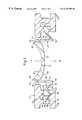
- FIG. 1diagrammatically shows a first valve and the adjacent part of the housing in which it is mounted, the valve being shown in central cross-section and in its retracted or “at rest” position;
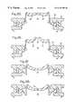
- FIGS. 2A through 2Gare views identical to FIG. 1 but to a smaller scale, showing the first valve at several stages during its operation to dispense product and subsequently return to its retracted position;
- FIG. 3shows the first valve in perspective view and as seen on a diametral section to a larger scale than FIGS. 1 and 2;
- FIGS. 4A through 4Cshow a second valve in accordance with the invention, in views similar to some of those of FIG. 2;
- FIGS. 5A through 5Ccorrespondingly show a third valve in accordance with the invention, in views similar to some of those of FIG. 2 .
- a self-closing valve 10is mounted in a housing 12 , only part of which is shown.
- the housinghas an opening 13 in which the valve is located.
- the housingforms part of a plastics closure which is itself mounted on a plastics container of a liquid food or other product.
- the closuremay be a snap cap but more usually it will be a screw cap.
- the container(not shown) is squeezable to expel product through the valve, and it is resilient so as after a dispensing operation to generate a negative pressure within the container headspace 14 and so cause the valve 10 to return to the as-moulded, retracted condition shown in FIG. 1 .
- the behaviour of the valve during its dispensing and retracting movementswill be described later in detail.
- the valve 10is a unitary moulding of a suitable flexible and resilient material, Liquid Silicon Rubber sold by Bayer under the trade name Silopren being preferred. It has three parts, namely a thickened mounting ring 20 which forms a continuous marginal region around the valve, a valve head 22 capable of movement axially of and within the mounting ring between the retracted position shown in FIG. 1 and the advanced position at which dispensing takes place—See FIGS. 2D, 2 E—and an imperforate connecting wall 24 which connects the mounting cup with the valve head.
- a suitable flexible and resilient materialLiquid Silicon Rubber sold by Bayer under the trade name Silopren being preferred. It has three parts, namely a thickened mounting ring 20 which forms a continuous marginal region around the valve, a valve head 22 capable of movement axially of and within the mounting ring between the retracted position shown in FIG. 1 and the advanced position at which dispensing takes place—See FIGS. 2D, 2 E—and an imperforate connecting wall 24 which connects the mounting
- the mounting ring 20is generally triangular in cross-section, having a cylindrical outer face 30 , and inclined upper and lower faces 26 and 28 which converge inwardly of the valve towards the attachment of the connecting wall 24 .
- the housing 12For engaging and holding the valve 10 the housing 12 has upper and lower parts 32 and 34 which are snap-engaged together by resilient engagement of complementary snap formations 36 and 38 . Opposed inclined surfaces of the parts engage the faces 26 , 28 of the mounting ring to hold it securely in position in a sealing manner.
- the lower part 34 of the housingforms an integral part of a screw closure onto which the upper part 32 is snap-engaged.
- the upper partmay be incorporated into the closure, and the lower part be provided as a separate component which is fitted to it.
- the valve head 22is concave to the exterior of the closure and is of progressively reducing thickness in the direction of its centre line XX from the cylindrical face 40 which forms its outer periphery. Its exterior face 42 is arcuate, and its interior face 48 is arcuate except at a central flat 51 . The outer cylindrical face 40 and the exterior face 42 converge to a sharply defined circular free edge 50 which forms the topmost point of the valve head as shown.
- valve head 22is formed with two identical straight cuts 52 A, 52 B, which intersect at their midpoints on the centreline XX.
- the cutsare orthogonal to one another, and each cut extends through the thickness of the valve head.
- the cutstherefore form four individually movable triangular tongues 53 attached to the valve head along the sides of a square and having their apices coincident on the centreline.
- FIG. 3One of the tongues is shown in full in FIG. 3 . Also visible in FIG. 3 is a ring formed of eight regularly spaced bosses 54 which project inwardly from the connecting wall 24 adjacent its bottom edge 55 . The bosses prevent nesting of the valves together prior to their automatic assembly into housings 12 . For clarity, they are omitted from the other drawings.
- the connecting wall 24has outer and inner parts 56 , 57 connected at an elbow 58 .
- the outer partis frustoconical, so as to extend inwardly and downwardly between the mounting ring 20 and the elbow.
- the inner part 57 of the connecting wallis cylindrical, extending axially between the elbow and a radially extending, short and thin, inturned flange 60 at which it is connected to the cylindrical outside face 40 of the valve head 22 .
- the height of the side face 40 of the valve headis 1.87 mm, and the thickness of the flange is 0.3 mm; thus, the valve head is more than six times the thickness of the flange at the junction between them.
- the flange 60is attached to the side face 40 of the valve head at a spacing of 0.46 mm below the top free edge 50 of the valve head.
- the part of the valve head lying above the flange and including the free edge 50accordingly defines an upwardly tapering and relatively compliant lip 59 which is capable of promoting drip-free product flow and of forming a product-tight seal against a flat surface of a travel cap (not shown) if required.
- the lipprojects above the surrounding upper surface of the housing at all times during operation of the valve.
- the outer part 56 of the connecting wall 24is inclined at an angle of 45° to the centreline XX of the valve, and therefore to the inner part 57 .
- the substantially V-shaped notch which is formed between the two partsis denoted by the reference numeral 72 .
- the material thickness of the outer wall part 56is uniform, at 0.31 mm.
- the inner wall part 57likewise has a uniform thickness, its thickness being 0.40 mm, that is, somewhat greater than that of the outer wall part and of the flange 60 .
- the outer wall part 56has upper and lower surfaces 62 , 64 respectively, the inner wall part 57 having outer and inner surfaces 66 , 68 .
- the bottom edge 55 of the connecting wall 24is a plane annular face formed where the inner wall part intersects the lower surface 64 of the outer wall part at the base of the elbow 58 .
- the material thickness at the elbowis therefore substantial, being 0.94 mm as measured from the bottom inner corner of the elbow to the acute-angled notch 72 at which the mutually facing surfaces 62 , 66 intersect one another.
- the elbowaccordingly has a substantial rigidity against forces which tend to open it by separating the surfaces 62 , 66 in its location; in particular it is capable of acting as a spring, as will later be described.
- FIG. 3illustrates a modification of the valve, in which the ring of spaced bosses 54 previously described is replaced by an inwardly projecting continuous bead 54 A of rectangular cross-section corresponding in location and cross-sectional dimensions (radial depth and axial height) to those of the ring of bosses.
- the beadincreases the stiffness of the connecting wall 24 at the elbow 58 , and assists in the valve moulding operation by enabling the valve to be held securely on the mould core until it can be stripped, under full control, from the mould core.
- FIG. 2show the valve in successive stages of its operation to dispense product and subsequently to retract with venting of air into the container interior.
- FIG. 2Ais a reproduction of FIG. 1 and shows the as-moulded, retracted position of the valve which occurs when little or no pressure differential exists across the wall of the container.
- the containerWhen it is required to dispense product the container is squeezed by the user to generate a substantial overpressure of, typically, 3 to 5 kPa within the container.
- the valve headrises, accompanied by inversion of the outer part 56 of the connecting wall 24 from its original “down” (i.e. downwardly and inwardly extending) position to the “up” (i.e. upwardly and inwardly extending) position which exists during product dispensing (See FIG. 2 E).
- the outer wall part 56In each of its “down” and “up” limiting positions the outer wall part 56 is generally frustoconical. In its movement between these positions it passes through the metastable intermediate condition shown in FIG. 2B, in which it has maximum internal stress and stored energy. It therefore imparts a desired bistable operating characteristic at a positive pressure to the valve. In FIG. 2C the outer wall part is approaching its “up” position; and in FIGS. 2D and 2E it has reached its “up” position.
- the movement of the outer wall part 56is largely passive, and caused by the generally axial forces transmitted to it by the inner wall part 57 .
- a minor part of the motive forcewill be generated by the product pressure on the outer wall part itself.
- the movement of the outer wall part 56is accompanied by hinging movement of the outer wall part on the mounting ring 20 at the attachment between them, together with opening of the elbow 58 to an obtuse angle of approximately 120° at its notch 72 .
- Some distortion of the wall parts 56 , 57 individuallywill also occur, both in response to the product pressure and in order to accommodate the opening of the elbow and its translational inward movements which accompany the inversion of the outer wall part.
- the outer wall partremains substantially frustoconical or plane, and the inner wall part remains substantially cylindrical.
- FIGS. 2A to 2 EA comparison of FIGS. 2A to 2 E clearly shows the behaviour of the valve head 22 during a movement from its retracted position in FIG. 2A to its advanced dispensing portion (FIG. 2 E). It will be seen that in response to product pressure the head becomes progressively less concave and flattened as the tongues 53 flex and hinge in an upward direction about their attachment to the remainder of the valve head. At about the time that the advanced position of the head is reached (FIG.
- the tonguespass a dead-centre position at which they are approximately coplanar; thereafter, with further flexing and hinging movement in the upward direction they separate from one another to leave an aperture generally in the form of a cross and through which product may be dispensed as indicated by the arrow 70 .
- FIG. 2Fshows this situation; the valve has the same general appearance as in FIGS. 1, 2 A and 3 , but at this time the pressure in the container headspace is becoming negative and venting is required to allow the container fully to resile.
- FIG. 2Gthe venting aperture is shown and indicated by the reference 71 . After venting the tongues return to their position shown in FIG. 2 F.
- the spring action of the elbow 58assists the movement of the valve head back to its retracted position after dispensing. This is of particular value where the associated container is of thin-walled construction (e.g. less than 0.4 mm or less in thickness) and has a corresponding limited resilience.
- the elbowensures a quick returning action of the valve and provides the valve with a positive “feel” for the user.
- the flange 60 by which the connecting wall 24 is attached to the valve head 22is thin, having a wall thickness of only 0.3 mm. It will be seen from FIGS. 2A to 2 E that as the valve moves towards its dispensing condition (FIG. 2E) the outer face 40 of the valve head and the part of the connecting wall 24 which lies opposite are required to separate from one another. Because it has little or no flexural stiffness, the flange presents little or no resistance to this separating movement. It acts essentially as a living hinge attachment by which translational movements of the valve head and the connecting wall may be transmitted from one to the other. Moreover, because the retracted position of the valve (shown in FIGS.
- the flange 60is also the as-moulded position in which it is manufactured, the flange 60 is substantially without stress when the valve is in that position. Because of this lack of stress any flexural stiffness which the flange does possess will not create torsional forces in the valve head in the sense to resist the distortion of the valve head which is required for it to vent, i.e. as depicted in FIG. 2 G. Applicants believe that the thickness of the flange 60 should be at most one third of the thickness of the valve head periphery.
- valve 10is exactly as has been described in relation to the first embodiment and accordingly it is not described again.
- the housing 12is modified by radially inward extension of its upper part 32 to provide an annular nose 74 .
- the connecting wall 24moves generally upwardly and outwardly during its movement for product dispensing, its elbow 58 comes into nesting engagement with this nose of the housing so as to define the vertical position which the head adopts for dispensing—See FIG. 4 C.
- the connecting walldoes not engage the housing, and the position of the head for dispensing is determined entirely by the dynamic balance of the forces in the connecting wall and the valve head.
- FIGS. 4A, 4 B and 4 Cshow stages of operation of the valve corresponding to those represented in FIGS. 2A, 2 B and 2 C respectively.
- the stages of operation corresponding to those of FIGS. 2D to 2 Elikewise correspond, but they are not shown.
- FIG. 5shows a third embodiment of the invention to be similar to that of FIG. 4 in that the dispensing position of the valve head 22 is likewise determined by engagement of the connecting wall 24 with the upper part 32 of the housing 12 .
- the engagementis made between the upper surface 62 of the outer wall part 56 and the complementary undersurface 75 of an annular nose 76 formed on the upper part 32 of the housing.
- FIG. 5its engagement with the housing 12 restricts the upward movement of the outer part 56 of the connecting wall 24 to the substantially horizontal and plane position shown in FIGS. 5B and 5C. This will be seen to correspond approximately to the unstable position represented in FIGS. 2B and 4B for the earlier embodiments.
- the outer wall part 56therefore assists the elbow 58 to return the valve resiliently to its retracted position after dispensing.
- FIGS. 5A, 5 B and 5 Ccan be considered to show the stages of operation which correspond to those of FIGS. 2A, 2 B and 2 E of the first embodiment.
- valve heads 22 and their attachments to the connecting wall 24 by the connecting valve 60are identical, and because of the isolating function of the connecting flange the valve heads operate in a substantially identical manner.
- the periphery of the valve head 22stands proud of the adjacent surrounding part of the housing 12 at all times, in particular in the “at rest” position of the valve. Together with the shape of the compliant portion 59 which forms the valve periphery, this proudness helps promote clean operation of the valve during dispensing, with little or no dripping when the container has been inverted again after dispensing in a valve-down position.
- the inventionmay have application to containers which are normally in a valve-down position, such for example, as liquid soap dispensers intended to be mounted in an inverted position on a wall, as well as to containers which require to be inverted for use.
Landscapes
- Engineering & Computer Science (AREA)
- Mechanical Engineering (AREA)
- Closures For Containers (AREA)
- Containers And Packaging Bodies Having A Special Means To Remove Contents (AREA)
- Cartons (AREA)
Abstract
Description
Claims (13)
Applications Claiming Priority (3)
| Application Number | Priority Date | Filing Date | Title |
|---|---|---|---|
| GB9717595 | 1997-08-21 | ||
| GBGB9717595.4AGB9717595D0 (en) | 1997-08-21 | 1997-08-21 | Valves for packaging containers |
| PCT/GB1998/002230WO1999010247A1 (en) | 1997-08-21 | 1998-07-27 | Valves for packaging containers |
Publications (1)
| Publication Number | Publication Date |
|---|---|
| US6273305B1true US6273305B1 (en) | 2001-08-14 |
Family
ID=10817739
Family Applications (1)
| Application Number | Title | Priority Date | Filing Date |
|---|---|---|---|
| US09/486,090Expired - LifetimeUS6273305B1 (en) | 1997-08-21 | 1998-07-27 | Valves for packaging containers |
Country Status (18)
| Country | Link |
|---|---|
| US (1) | US6273305B1 (en) |
| EP (1) | EP1005430B1 (en) |
| JP (1) | JP4253119B2 (en) |
| CN (1) | CN1106994C (en) |
| AR (1) | AR013421A1 (en) |
| AT (1) | ATE225292T1 (en) |
| AU (1) | AU739728B2 (en) |
| BR (1) | BR9811312A (en) |
| CA (1) | CA2297211C (en) |
| CO (1) | CO4810388A1 (en) |
| DE (1) | DE69808491T2 (en) |
| ES (1) | ES2180188T3 (en) |
| GB (1) | GB9717595D0 (en) |
| MY (1) | MY117584A (en) |
| PL (1) | PL193965B1 (en) |
| RU (1) | RU2198122C2 (en) |
| TW (1) | TW415904B (en) |
| WO (1) | WO1999010247A1 (en) |
Cited By (31)
| Publication number | Priority date | Publication date | Assignee | Title |
|---|---|---|---|---|
| US6533145B2 (en) | 2000-12-19 | 2003-03-18 | Kimberly-Clark Worldwide, Inc. | Self-contained viscous liquid dispenser |
| US6540117B2 (en) | 2001-03-30 | 2003-04-01 | Kimberly-Clark Worldwide, Inc. | Dosing pump for liquid dispensers |
| US6616016B2 (en)* | 2001-12-07 | 2003-09-09 | Seaquist Closures Foreign, Inc. | Closure with pressure-actuated valve and lid seal |
| US20030168455A1 (en)* | 2002-03-08 | 2003-09-11 | Zettle Jeffrey J. | Container lid with selectable opening and valve assembly for retaining a valve |
| US6749092B2 (en)* | 2001-08-10 | 2004-06-15 | Seaquist Closures Foreign, Inc. | Deformable dispensing valve |
| USD495604S1 (en) | 2002-09-26 | 2004-09-07 | Johnson & Johnson Consumer Companies, Inc. | Bottle |
| USD497108S1 (en) | 2002-09-26 | 2004-10-12 | Douglas M. Lund | Bottle |
| US20040200738A1 (en)* | 2003-04-09 | 2004-10-14 | Capsol Berry Plastics S.P.A. | Elastically deformable valve with automatic closure for the controlled dispensing of fluids from fluid containers |
| US20040238576A1 (en)* | 2001-07-23 | 2004-12-02 | Mcgill Shane Robert | Container with outlet |
| US20050159724A1 (en)* | 2003-12-18 | 2005-07-21 | Enerson Jon R. | Needleless access vial |
| US20060037977A1 (en)* | 2004-08-18 | 2006-02-23 | John Eimer | Container closure |
| US20060037976A1 (en)* | 2004-08-18 | 2006-02-23 | John Eimer | Container closure |
| US20060049208A1 (en)* | 2004-09-09 | 2006-03-09 | Daansen Warren S | Slit valves and dispensing nozzles employing same |
| US20060113331A1 (en)* | 2004-11-30 | 2006-06-01 | Kranson Industries, Inc., D/B/A Tricorbraun | Molded collapsible blow dome apparatus and method |
| US20060201976A1 (en)* | 2005-03-09 | 2006-09-14 | Owens-Illinois Closure Inc. | Integrally molded dispensing valve and method of manufacture |
| US20060249545A1 (en)* | 2003-05-07 | 2006-11-09 | Crown Packaging Technology Inc. | Valve closure |
| US20080009822A1 (en)* | 2003-12-18 | 2008-01-10 | Halkey-Roberts Corporation | Needleless access vial |
| US20080035677A1 (en)* | 2004-09-09 | 2008-02-14 | Daansen Warren S | Nozzle tip with slit valve for fluid dispenser |
| US20080237271A1 (en)* | 2007-03-27 | 2008-10-02 | Liquid Molding Systems, Inc. | Dispensing valve with improved dispensing |
| US20080264979A1 (en)* | 2007-02-14 | 2008-10-30 | Avesto Tech B.V. | Dispensing valve and a container for holding fluid provided with such a dispensing valve |
| WO2009127801A1 (en)* | 2008-04-18 | 2009-10-22 | Obrist Closures Switzerland Gmbh | Valves for packaging containers |
| US20090267011A1 (en)* | 2008-04-23 | 2009-10-29 | Jason Hatton | Dispensing valve assembly |
| US20100084397A1 (en)* | 2006-11-27 | 2010-04-08 | Tomohiko Kubo | Liquid agent container |
| US20100096416A1 (en)* | 2008-10-15 | 2010-04-22 | Gaetan Painchaud | Liquid dispensing device equipped with a sealing component moveable under the effect of pressure by a user |
| US20110163134A1 (en)* | 2010-01-06 | 2011-07-07 | Bloom Kenneth S | Dispensing valve |
| US20140224356A1 (en)* | 2011-05-04 | 2014-08-14 | Aptargroup, Inc. | Port closure system for use with a probe/feed/drain tool |
| USD728378S1 (en) | 2013-03-15 | 2015-05-05 | Tc Heartland Llc | Container |
| US9481495B2 (en)* | 2014-04-24 | 2016-11-01 | Scholle Ipn Corporation | Dispensing system |
| US10442584B2 (en)* | 2015-02-03 | 2019-10-15 | Weener Plastics Netherlands B.V. | Dispensing closure with self-closing valve |
| US10518943B2 (en) | 2013-03-15 | 2019-12-31 | Tc Heartland Llc | Container with valve |
| US10836541B2 (en) | 2017-11-27 | 2020-11-17 | Gateway Plastics, Inc. | Valve for a dispensing container |
Families Citing this family (29)
| Publication number | Priority date | Publication date | Assignee | Title |
|---|---|---|---|---|
| US5839614A (en) | 1991-12-06 | 1998-11-24 | Aptar Group, Inc. | Dispensing package |
| CN1079355C (en)* | 1995-09-05 | 2002-02-20 | 策拉塑料有限公司 | Self-closing seal and sealing film |
| US6062436A (en)* | 1998-04-02 | 2000-05-16 | Owens-Illinois Closure Inc. | Flexible vented self-sealing dispensing valve |
| ES2376730T3 (en) | 2000-07-24 | 2012-03-16 | Obrist Closures Switzerland Gmbh | Activating ring for a closure membrane |
| US6405901B1 (en) | 2000-12-22 | 2002-06-18 | Seaquist Closures Foreign, Inc. | Valve with rolling sleeve |
| US6293437B1 (en) | 2000-12-22 | 2001-09-25 | Seaquist Closures Foreign, Inc. | Valve with rolling sleeve |
| US7086572B2 (en)* | 2004-03-26 | 2006-08-08 | Seaquist Closures Foreign, Inc. | Valve for dispensing product |
| EP1531130A1 (en)* | 2004-08-26 | 2005-05-18 | CROWN Packaging Technology, Inc | Valve retaining device |
| US7398900B2 (en)* | 2005-01-28 | 2008-07-15 | Owens-Illinois Closure Inc. | Dispensing closure, package and method of manufacture |
| RU2386071C2 (en)* | 2005-10-29 | 2010-04-10 | Пифлекс П/С | Pipeline for fluid medium and method of its manufacturing |
| ITMO20060252A1 (en)* | 2006-08-04 | 2008-02-05 | Mrp Medical Res & Promotion Es | BOTTLE FOR FLUID CONTAINMENT, PARTICULARLY FOR PHARMACEUTICAL OR SIMILAR PRODUCTS |
| EP2121467B1 (en)* | 2006-12-20 | 2011-05-25 | Plasticum Group B.V. | Closure assembly with valve and method for its manufacturing |
| US7980430B2 (en)* | 2007-01-19 | 2011-07-19 | Seaquist Closures L.L.C. | Valve carrier ring assembly |
| US7784652B2 (en) | 2007-03-27 | 2010-08-31 | Liquid Molding Systems, Inc. | Dispensing valve with hydraulic hammer resistance |
| GB2451493B (en) | 2007-07-31 | 2011-12-14 | Magicup Marketing Ltd | Closure device for a fluid vessel |
| US8678249B2 (en) | 2008-02-21 | 2014-03-25 | Aptargroup, Inc. | Valve mounting assembly with slit misalignment prevention feature |
| US8079385B2 (en)* | 2008-04-09 | 2011-12-20 | Liquid Molding Systems, Inc. | Valve assembly |
| US8316890B2 (en) | 2008-11-11 | 2012-11-27 | Aptargroup, Inc. | Port closure system with hydraulic hammer resistance |
| JP2013193740A (en)* | 2012-03-15 | 2013-09-30 | Kikkoman Corp | Check valve |
| DE102013221706A1 (en)* | 2013-10-25 | 2015-04-30 | Robert Bosch Gmbh | Method for the metered dispensing of liquid ingredients from a tubular bag and means for carrying out the method |
| WO2015150546A1 (en) | 2014-04-03 | 2015-10-08 | Obrist Closures Switzerland Gmbh | Valve retaining device |
| JP6547267B2 (en)* | 2014-09-30 | 2019-07-24 | 凸版印刷株式会社 | Mouthpiece |
| JP2017030846A (en)* | 2015-08-06 | 2017-02-09 | 株式会社三谷バルブ | Back suction mechanism using cup rubber, double container comprising this back suction mechanism, and squeeze operation mode pump type product comprising this double container |
| PL3492400T3 (en)* | 2017-11-30 | 2020-08-10 | The Procter & Gamble Company | LIQUID DISPENSER FOR INVERTED CONTAINER |
| CN108557247A (en)* | 2018-06-11 | 2018-09-21 | 奥星衡迅生命科技(上海)有限公司 | A kind of plastic containers that can make up tolerance automatically |
| NL2022764B1 (en) | 2019-03-19 | 2020-09-28 | Weener Plastics Group B V | Self-closing dispensing valve made of a plastomer or a thermoplastic elastomer |
| GB201905182D0 (en) | 2019-04-11 | 2019-05-29 | Obrist Closures Switzerland | Valve |
| JP7319401B2 (en)* | 2019-07-09 | 2023-08-01 | ザ プロクター アンド ギャンブル カンパニー | Multi-composition product dispenser |
| FR3114575B1 (en)* | 2020-09-29 | 2022-09-23 | Promens Sa | Dispensing device comprising a non-return valve with a hard point |
Citations (3)
| Publication number | Priority date | Publication date | Assignee | Title |
|---|---|---|---|---|
| US5213236A (en)* | 1991-12-06 | 1993-05-25 | Liquid Molding Systems, Inc. | Dispensing valve for packaging |
| US5409144A (en)* | 1991-12-06 | 1995-04-25 | Liquid Molding Systems Inc. | Dispensing valve for packaging |
| US5839614A (en)* | 1991-12-06 | 1998-11-24 | Aptar Group, Inc. | Dispensing package |
Family Cites Families (8)
| Publication number | Priority date | Publication date | Assignee | Title |
|---|---|---|---|---|
| US2175052A (en) | 1938-09-02 | 1939-10-03 | Us Rubber Co | Dispenser cap and method of making same |
| FR996998A (en) | 1949-10-06 | 1951-12-31 | Closing device for collapsible tubes | |
| US2758755A (en) | 1953-04-15 | 1956-08-14 | Schafler Kay | Compressible container with automatically closing and retracting discharge nozzle |
| US4991745A (en) | 1989-04-25 | 1991-02-12 | Liquid Molding Systems, Inc. | Dispensing valve with trampoline-like construction |
| US5377861A (en)* | 1993-01-13 | 1995-01-03 | Landis Plastics, Inc. | Container closure with external ribs |
| DE19613130A1 (en)* | 1995-09-05 | 1997-03-06 | Design Udo Suffa Gmbh S | Self-closing closure and membrane |
| DE19640130A1 (en)* | 1996-09-28 | 1998-04-02 | Dittrich Schluessel Kg | Production of injected-gas foamed mouldings with bonded surface skin in all desired locations |
| DE19640629A1 (en)* | 1996-10-01 | 1998-04-02 | Zeller Plastik Koehn Graebner | Sealing membrane |
- 1997
- 1997-08-21GBGBGB9717595.4Apatent/GB9717595D0/ennot_activeCeased
- 1998
- 1998-07-27CACA002297211Apatent/CA2297211C/ennot_activeExpired - Fee Related
- 1998-07-27BRBR9811312-7Apatent/BR9811312A/ennot_activeIP Right Cessation
- 1998-07-27DEDE69808491Tpatent/DE69808491T2/ennot_activeExpired - Lifetime
- 1998-07-27EPEP98935217Apatent/EP1005430B1/ennot_activeExpired - Lifetime
- 1998-07-27RURU2000106745/13Apatent/RU2198122C2/ennot_activeIP Right Cessation
- 1998-07-27PLPL98338782Apatent/PL193965B1/enunknown
- 1998-07-27AUAU84563/98Apatent/AU739728B2/ennot_activeCeased
- 1998-07-27ATAT98935217Tpatent/ATE225292T1/enactive
- 1998-07-27USUS09/486,090patent/US6273305B1/ennot_activeExpired - Lifetime
- 1998-07-27WOPCT/GB1998/002230patent/WO1999010247A1/enactiveIP Right Grant
- 1998-07-27CNCN98808298Apatent/CN1106994C/ennot_activeExpired - Fee Related
- 1998-07-27ESES98935217Tpatent/ES2180188T3/ennot_activeExpired - Lifetime
- 1998-07-27JPJP2000507590Apatent/JP4253119B2/ennot_activeExpired - Fee Related
- 1998-07-31TWTW087112657Apatent/TW415904B/ennot_activeIP Right Cessation
- 1998-08-14ARARP980104049Apatent/AR013421A1/enactiveIP Right Grant
- 1998-08-21MYMYPI98003837Apatent/MY117584A/enunknown
- 1998-08-21COCO98047969Apatent/CO4810388A1/enunknown
Patent Citations (6)
| Publication number | Priority date | Publication date | Assignee | Title |
|---|---|---|---|---|
| US5213236A (en)* | 1991-12-06 | 1993-05-25 | Liquid Molding Systems, Inc. | Dispensing valve for packaging |
| US5339995A (en)* | 1991-12-06 | 1994-08-23 | Liquid Molding Systems, Inc. | Dispensing valve for packaging |
| US5377877A (en)* | 1991-12-06 | 1995-01-03 | Liquid Molding Systems, Inc. | Dispensing valve for packaging |
| US5409144A (en)* | 1991-12-06 | 1995-04-25 | Liquid Molding Systems Inc. | Dispensing valve for packaging |
| US5439143A (en)* | 1991-12-06 | 1995-08-08 | Liquid Molding Systems, Inc. | Dispensing valve for packaging |
| US5839614A (en)* | 1991-12-06 | 1998-11-24 | Aptar Group, Inc. | Dispensing package |
Cited By (57)
| Publication number | Priority date | Publication date | Assignee | Title |
|---|---|---|---|---|
| US6729502B2 (en) | 2000-12-19 | 2004-05-04 | Kimberly-Clark Worldwide, Inc. | Self-contained viscous liquid dispenser |
| US6543651B2 (en) | 2000-12-19 | 2003-04-08 | Kimberly-Clark Worldwide, Inc. | Self-contained viscous liquid dispenser |
| US6575335B2 (en) | 2000-12-19 | 2003-06-10 | Kimberly-Clark Worldwide, Inc. | Self-contained viscous liquid dispenser |
| US6575334B2 (en) | 2000-12-19 | 2003-06-10 | Kimberly-Clark Worldwide, Inc. | Self-contained viscous liquid dispenser |
| US6533145B2 (en) | 2000-12-19 | 2003-03-18 | Kimberly-Clark Worldwide, Inc. | Self-contained viscous liquid dispenser |
| US6648179B2 (en) | 2000-12-19 | 2003-11-18 | Kimberly-Clark Worldwide, Inc. | Self-contained viscous liquid dispenser |
| US6540117B2 (en) | 2001-03-30 | 2003-04-01 | Kimberly-Clark Worldwide, Inc. | Dosing pump for liquid dispensers |
| US20040238576A1 (en)* | 2001-07-23 | 2004-12-02 | Mcgill Shane Robert | Container with outlet |
| US6749092B2 (en)* | 2001-08-10 | 2004-06-15 | Seaquist Closures Foreign, Inc. | Deformable dispensing valve |
| US6616016B2 (en)* | 2001-12-07 | 2003-09-09 | Seaquist Closures Foreign, Inc. | Closure with pressure-actuated valve and lid seal |
| RU2296087C2 (en)* | 2001-12-07 | 2007-03-27 | Сиквист Клоужерз Форин, Инк. | Closing device with pressure operated valve and sealed cover |
| US20030168455A1 (en)* | 2002-03-08 | 2003-09-11 | Zettle Jeffrey J. | Container lid with selectable opening and valve assembly for retaining a valve |
| USD495604S1 (en) | 2002-09-26 | 2004-09-07 | Johnson & Johnson Consumer Companies, Inc. | Bottle |
| USD497108S1 (en) | 2002-09-26 | 2004-10-12 | Douglas M. Lund | Bottle |
| US20040200738A1 (en)* | 2003-04-09 | 2004-10-14 | Capsol Berry Plastics S.P.A. | Elastically deformable valve with automatic closure for the controlled dispensing of fluids from fluid containers |
| US20060249545A1 (en)* | 2003-05-07 | 2006-11-09 | Crown Packaging Technology Inc. | Valve closure |
| US20050159724A1 (en)* | 2003-12-18 | 2005-07-21 | Enerson Jon R. | Needleless access vial |
| US20080009822A1 (en)* | 2003-12-18 | 2008-01-10 | Halkey-Roberts Corporation | Needleless access vial |
| US20080061469A1 (en)* | 2004-08-18 | 2008-03-13 | Seaquist Closures L.L.C. | Container Closure |
| US7842215B2 (en) | 2004-08-18 | 2010-11-30 | Seaquist Closures L.L.C. | Process of forming a container closure |
| US7306128B2 (en) | 2004-08-18 | 2007-12-11 | Seaquist Closures L.L.C. | Container closure |
| US7306127B2 (en) | 2004-08-18 | 2007-12-11 | Seaquist Closures L.L.C. | Container closure |
| US20060037976A1 (en)* | 2004-08-18 | 2006-02-23 | John Eimer | Container closure |
| US20060037977A1 (en)* | 2004-08-18 | 2006-02-23 | John Eimer | Container closure |
| US9254498B2 (en) | 2004-09-09 | 2016-02-09 | Warren S. Daansen | Nozzle tip with slit valve for fluid dispenser |
| US20060049208A1 (en)* | 2004-09-09 | 2006-03-09 | Daansen Warren S | Slit valves and dispensing nozzles employing same |
| US20080035677A1 (en)* | 2004-09-09 | 2008-02-14 | Daansen Warren S | Nozzle tip with slit valve for fluid dispenser |
| US8899449B2 (en) | 2004-09-09 | 2014-12-02 | Warren S. Daansen | Nozzle tip with slit valve for fluid dispenser |
| US9714714B2 (en) | 2004-09-09 | 2017-07-25 | Warren S. Daansen | Nozzle tip with slit valve for fluid dispenser |
| US20060113331A1 (en)* | 2004-11-30 | 2006-06-01 | Kranson Industries, Inc., D/B/A Tricorbraun | Molded collapsible blow dome apparatus and method |
| RU2412882C2 (en)* | 2005-03-09 | 2011-02-27 | Риксэм Клоужур Системз Инк | Whole-moulded metering valve and method of its fabrication |
| US7503469B2 (en) | 2005-03-09 | 2009-03-17 | Rexam Closure Systems Inc. | Integrally molded dispensing valve and method of manufacture |
| US20060201976A1 (en)* | 2005-03-09 | 2006-09-14 | Owens-Illinois Closure Inc. | Integrally molded dispensing valve and method of manufacture |
| WO2006098826A3 (en)* | 2005-03-09 | 2007-01-11 | Owens Illinois Closure Inc | Integrally molded dispensing valve and method of manufacture |
| US9308150B2 (en)* | 2006-11-27 | 2016-04-12 | Nipro Corporation | Liquid agent container |
| US20100084397A1 (en)* | 2006-11-27 | 2010-04-08 | Tomohiko Kubo | Liquid agent container |
| US20080264979A1 (en)* | 2007-02-14 | 2008-10-30 | Avesto Tech B.V. | Dispensing valve and a container for holding fluid provided with such a dispensing valve |
| US8397956B2 (en) | 2007-03-27 | 2013-03-19 | Aptargroup, Inc. | Dispensing valve with improved dispensing |
| US20080237271A1 (en)* | 2007-03-27 | 2008-10-02 | Liquid Molding Systems, Inc. | Dispensing valve with improved dispensing |
| WO2009127801A1 (en)* | 2008-04-18 | 2009-10-22 | Obrist Closures Switzerland Gmbh | Valves for packaging containers |
| US20090267011A1 (en)* | 2008-04-23 | 2009-10-29 | Jason Hatton | Dispensing valve assembly |
| US8794490B2 (en)* | 2008-10-15 | 2014-08-05 | Rexam Healthcare La Verpilliere | Liquid dispensing device equipped with a sealing component moveable under the effect of pressure by a user |
| US20100096416A1 (en)* | 2008-10-15 | 2010-04-22 | Gaetan Painchaud | Liquid dispensing device equipped with a sealing component moveable under the effect of pressure by a user |
| US8397957B2 (en)* | 2010-01-06 | 2013-03-19 | Berry Plastics Corporation | Dispensing valve |
| US8794489B2 (en) | 2010-01-06 | 2014-08-05 | Berry Plastics Corporation | Dispensing valve |
| US20110163134A1 (en)* | 2010-01-06 | 2011-07-07 | Bloom Kenneth S | Dispensing valve |
| US9580214B2 (en)* | 2011-05-04 | 2017-02-28 | Aptargroup, Inc. | Port closure system for use with a probe/feed/drain tool |
| US20140224356A1 (en)* | 2011-05-04 | 2014-08-14 | Aptargroup, Inc. | Port closure system for use with a probe/feed/drain tool |
| USD863064S1 (en) | 2013-03-15 | 2019-10-15 | Tc Heartland Llc | Container |
| USD801827S1 (en) | 2013-03-15 | 2017-11-07 | Tc Heartland Llc | Container |
| USD728378S1 (en) | 2013-03-15 | 2015-05-05 | Tc Heartland Llc | Container |
| US10518943B2 (en) | 2013-03-15 | 2019-12-31 | Tc Heartland Llc | Container with valve |
| USD945886S1 (en) | 2013-03-15 | 2022-03-15 | Tc Heartland Llc | Container |
| US9481495B2 (en)* | 2014-04-24 | 2016-11-01 | Scholle Ipn Corporation | Dispensing system |
| US10442584B2 (en)* | 2015-02-03 | 2019-10-15 | Weener Plastics Netherlands B.V. | Dispensing closure with self-closing valve |
| US10836541B2 (en) | 2017-11-27 | 2020-11-17 | Gateway Plastics, Inc. | Valve for a dispensing container |
| US11377266B2 (en) | 2017-11-27 | 2022-07-05 | Silgan Specialty Packaging Llc | Valve for a dispensing container |
Also Published As
| Publication number | Publication date |
|---|---|
| DE69808491D1 (en) | 2002-11-07 |
| DE69808491T2 (en) | 2003-01-30 |
| CN1106994C (en) | 2003-04-30 |
| AU739728B2 (en) | 2001-10-18 |
| PL193965B1 (en) | 2007-04-30 |
| WO1999010247A1 (en) | 1999-03-04 |
| ES2180188T3 (en) | 2003-02-01 |
| CN1267269A (en) | 2000-09-20 |
| JP2001514130A (en) | 2001-09-11 |
| EP1005430B1 (en) | 2002-10-02 |
| RU2198122C2 (en) | 2003-02-10 |
| CA2297211C (en) | 2007-11-13 |
| GB9717595D0 (en) | 1997-10-22 |
| PL338782A1 (en) | 2000-11-20 |
| CO4810388A1 (en) | 1999-06-30 |
| TW415904B (en) | 2000-12-21 |
| CA2297211A1 (en) | 1999-03-04 |
| AU8456398A (en) | 1999-03-16 |
| JP4253119B2 (en) | 2009-04-08 |
| ATE225292T1 (en) | 2002-10-15 |
| MY117584A (en) | 2004-07-31 |
| EP1005430A1 (en) | 2000-06-07 |
| BR9811312A (en) | 2000-08-29 |
| AR013421A1 (en) | 2000-12-27 |
Similar Documents
| Publication | Publication Date | Title |
|---|---|---|
| US6273305B1 (en) | Valves for packaging containers | |
| EP0994037B1 (en) | Dispensing valve | |
| EP1426303B1 (en) | Valve for a fluid dispensing package | |
| EP1131252B1 (en) | Dispensing closures | |
| EP0929464B1 (en) | Closure membrane | |
| EP1451075B1 (en) | Closure with pressure-actuated valve and lid seal | |
| USH2027H1 (en) | Flexible slit valve | |
| MX2007006941A (en) | Flow control element and dispensing structure incorporating same. | |
| WO2013175216A1 (en) | A dispensing valve | |
| MXPA00001816A (en) | Valves for packaging containers | |
| HK1011667B (en) | Dispensing valve | |
| HK1024895B (en) | Dispensing valve | |
| HK1024894B (en) | Dispensing valve for a package | |
| HK1056159A1 (en) | One-piece dispensing system and method for making same | |
| HK1056159B (en) | One-piece dispensing system and method for making same |
Legal Events
| Date | Code | Title | Description |
|---|---|---|---|
| AS | Assignment | Owner name:CROWN CORK & SEAL TECHNOLOGIES CORPORATION, ILLINO Free format text:ASSIGNMENT OF ASSIGNORS INTEREST;ASSIGNORS:FIORAVANTI, ALEX;RAMSEY, CHRISTOPHER PAUL;REEL/FRAME:010675/0961 Effective date:20000112 | |
| STCF | Information on status: patent grant | Free format text:PATENTED CASE | |
| AS | Assignment | Owner name:CROWN CORK & SEAL TECHNOLOGIES, ILLINOIS Free format text:RELEASE OF SECURITY INTEREST;ASSIGNOR:JPMORGAN CHASE BANK;REEL/FRAME:013798/0522 Effective date:20030226 | |
| AS | Assignment | Owner name:CITICORP NORTH AMERICA, INC., AS COLLATERAL AGENT, Free format text:SECURITY INTEREST;ASSIGNOR:CROWN CORK & SEAL TECHNOLOGIES CORPORATION;REEL/FRAME:013791/0846 Effective date:20030226 | |
| FEPP | Fee payment procedure | Free format text:PAYOR NUMBER ASSIGNED (ORIGINAL EVENT CODE: ASPN); ENTITY STATUS OF PATENT OWNER: LARGE ENTITY | |
| FPAY | Fee payment | Year of fee payment:4 | |
| AS | Assignment | Owner name:CITICORP NORTH AMERICA, INC., NEW YORK Free format text:SECURITY AGREEMENT;ASSIGNOR:CROWN TECHNOLOGIES PACKAGING CORPORATION;REEL/FRAME:016283/0612 Effective date:20040901 | |
| AS | Assignment | Owner name:CROWN OBRIST GMBH, SWITZERLAND Free format text:ASSIGNMENT OF ASSIGNORS INTEREST;ASSIGNOR:CROWN PACKAGING TECHNOLOGY, INC.;REEL/FRAME:017546/0384 Effective date:20051011 | |
| AS | Assignment | Owner name:CROWN PACKAGING TECHNOLOGY, INC., ILLINOIS Free format text:CHANGE OF NAME;ASSIGNOR:CROWN CORK & SEAL TECHNOLOGIES CORPORATION;REEL/FRAME:018573/0199 Effective date:20031103 | |
| AS | Assignment | Owner name:OBRIST CLOSURES SWITZERLAND GMBH, SWITZERLAND Free format text:ASSIGNMENT OF ASSIGNORS INTEREST;ASSIGNOR:CROWN OBRIST GMBH;REEL/FRAME:018645/0465 Effective date:20051220 | |
| FPAY | Fee payment | Year of fee payment:8 | |
| FPAY | Fee payment | Year of fee payment:12 | |
| AS | Assignment | Owner name:CROWN PACKAGING TECHNOLOGY, INC., ILLINOIS Free format text:RELEASE BY SECURED PARTY;ASSIGNOR:CITICORP NORTH AMERICA, INC.;REEL/FRAME:032449/0281 Effective date:20140314 Owner name:CROWN PACKAGING TECHNOLOGY, INC., ILLINOIS Free format text:RELEASE BY SECURED PARTY;ASSIGNOR:CITICORP NORTH AMERICA, INC.;REEL/FRAME:032449/0248 Effective date:20140314 |