US6273276B1 - Gravity flow shelving system - Google Patents
Gravity flow shelving systemDownload PDFInfo
- Publication number
- US6273276B1 US6273276B1US09/283,639US28363999AUS6273276B1US 6273276 B1US6273276 B1US 6273276B1US 28363999 AUS28363999 AUS 28363999AUS 6273276 B1US6273276 B1US 6273276B1
- Authority
- US
- United States
- Prior art keywords
- rack
- rails
- rail
- bend
- stop member
- Prior art date
- Legal status (The legal status is an assumption and is not a legal conclusion. Google has not performed a legal analysis and makes no representation as to the accuracy of the status listed.)
- Expired - Fee Related
Links
Images


Classifications
- A—HUMAN NECESSITIES
- A47—FURNITURE; DOMESTIC ARTICLES OR APPLIANCES; COFFEE MILLS; SPICE MILLS; SUCTION CLEANERS IN GENERAL
- A47F—SPECIAL FURNITURE, FITTINGS, OR ACCESSORIES FOR SHOPS, STOREHOUSES, BARS, RESTAURANTS OR THE LIKE; PAYING COUNTERS
- A47F1/00—Racks for dispensing merchandise; Containers for dispensing merchandise
- A47F1/04—Racks or containers with arrangements for dispensing articles, e.g. by means of gravity or springs
- A47F1/12—Racks or containers with arrangements for dispensing articles, e.g. by means of gravity or springs dispensing from the side of an approximately horizontal stack
- A47F1/121—Racks or containers with arrangements for dispensing articles, e.g. by means of gravity or springs dispensing from the side of an approximately horizontal stack made of tubes or wire
Definitions
- the present inventionrelates generally to container storage racks and more particularly to gravity flow shelving systems adapted for the display and storage of a variety of merchandise.
- the present inventionfeatures a versatile shelving system having easily adjustable and insertable racks to adapt to a variety of merchandising arrangements.
- the systemis particularly useful for gravity feed shelving applications.
- Prior art gravity flow racksgenerally include an assembly of vertically spaced racks angled downwardly and forwardly, providing more shelf space than flat shelving units. During gravity flow, substantial slidable contact is made between the bottom surface of the merchandise and the upper surface of the rack. To expedite the sliding movement, each rack typically features a low friction track surface so that when a purchaser removes merchandise from the front of the rack, the remainder of the merchandise slides forward to facilitate handling by the next purchaser. This provides a natural first in first out (FIFO) movement to ensure that earlier-dated items are sold first.
- FIFOfirst in first out
- Shelving systemsneed to be adaptable to accommodate various types of merchandise containers, product profiles, and seasonal merchandise. For instance, fresh liquids are primarily packaged in square paper-product containers coated with suitable plastics or paraffin. Other merchandise may include canned beverages, along with glass or plastic bottles and encompass a wide range of container sizes and shapes. As merchandising needs change, the prior shelving system or arrangement may be unsuitable for a new product.
- Another object of the inventionis to provide a gravity flow rack in which the rack is made from predominantly inexpensive wire or inexpensive plastics.
- a further objectis to provide a gravity feed shelf in which advertising or pricing labels may be easily inserted to facilitate the merchandising of the containers.
- Yet another objectis to provide an insertable organizing rack which may be used with both conventional gravity feed and flat wire shelving to organize the shelf merchandise.
- a still further objectis to provide a organizing rack for a shelf having component parts that are easy to assemble and interchange so as to accommodate different types and sizes of containers.
- Still another objectis to provide a rack and shelf assembly that is relatively inexpensive to make.
- a further objectis to provide a rack that is easy to disassemble and clean.
- Yet another objectis to provide a gravity flow rack that will be compatible with existing gravity shelves.
- a still further object of the inventionis to provide a gravity flow rack that is attractive and decorative.
- Another object of this inventionis to provide a rack insert which is reversible to accommodate merchandise of varying height.
- Another objectis to provide shelving for a gravity flow rack that is lightweight yet durable and relatively strong.
- An additional objectis to provide a gravity flow rack in which the racked items automatically are maintained in the proper order and in which the front of each succeeding item automatically moves into place on the front face of the rack when a preceding item is removed from the rack.
- a gravity flow shelf assemblycomprising: a rack having a first rail and a second rail, the first and the second rails positioned a spaced distance apart and defining a sleeve therebetween, the first rail having a front shank, a rear shank, and an inter-connecting segment, the interconnecting segment connected to the front shank along the first bend and further connected to the rear shank along a second bend; the second rail having a front shank, a rear shank, and an interconnecting segment, the inter-connecting segment connected to the front shank along the first bend and further connected to the rear shank along the second bend; a first stop member, carried by and positioned between the first front shank and the second rail front shank; a second stop carried by and positioned between the first rail rear shank and the rail rear shank; a first engaging member defined by a terminal free end of at least one of the first or the second front shank and a second engaging member defined by a terminal free
- FIG. 1is an example of a prior art gravity shelf rack using a plastic clip to join an organizer to a lower support rack.
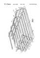
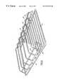
- FIG. 2is a top, front perspective view of a gravity feed shelf in which an organizing rack of the present invention is installed onto the support racks to provide merchandise dividers.
- FIG. 3is a side perspective view of a merchandise shelf carrying an organizing rack in accordance with the present invention.
- FIG. 4is a side elevation of a organizing rack in association with a product shelf assembly.
- FIG. 5is another side elevation view illustrating the attachment of the organizing rack to the lower shelf support rack.
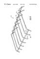
- FIG. 6is a front perspective view of the separator organizer rack mounted on the shelf.
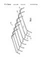
- FIGS. 7-9are front perspective views of different embodiments of organizing racks.
- FIG. 1a prior art gravity rack is illustrated which comprises a lower shelf support rack A which may be positioned at a downward angle within a refrigerator enclosure.
- Support rack Amay be secured within the enclosure through any of a variety of well-know securing means.
- a clip Bis attached along two inner curved portions to respective rails of support rack A.
- Clip Bfurther defines a U-shaped channel C to which an overhead organizing rack D is attached.
- the front surface of clip Bmay be used as a flavor strip to accommodate advertising and product promotional information. While clip B is functional with respect to allowing an organizing rack to be installed, the clip is time consuming to operate and inconvenient to use. Further, the clips are subject to breakage over time through temperature extremes and normal wear as the gravity feed product continually slides against the clip.
- the present inventionprovides an improved organizing rack which is designed to be inserted between the front and rear rails of an existing wire shelf.
- the rackis particularly useful with respect to gravity feed shelves but also offers advantages when used with conventional flat shelving.
- the organizing rackis held in place by the spring tension between engagement prongs of the organizing rack and the support rails of the wire shelf.
- a refrigeration unit 1provides a series of wire shelves 10 .
- a removable organizing rack 20is positioned between the front shelf rails and the rear shelf rails.
- a wire shelf 10defines a plurality of rounded support grids 11 connecting a shelf front 12 to a shelf rear 14 .
- the front 12 and rear 14 shelffurther defines a respective reinforcing bar 16 which is welded to support posts 18 and which maintains the bar in an elevated, floating profile above the front and rear of the shelf 10 .
- Organizing rack 20is provided by a plurality of guide rails 22 .
- Each guide rail 22has a substantially straight mid section with opposing downwardly angled shank portions 24 and 26 at respective ends of rail 22 .
- a terminus of shank portion 24 and 26each defines an engaging means seen in the form of an arcuate clip, prong, or clasp 28 .
- the curvature of clasp 28is adapted for engaging the outer circumference of support rail 16 .
- the respective shape of clasp 28may be varied to accommodate the size and shape of the corresponding support rail.
- a curved shape to the engaging memberis useful in that the shape is compatible with the majority of support shelves which uses round wire construction.
- Guide rails 22are attached by a weld or other suitable mechanism to a front stop 30 and a rear stop 32 which collectively secures the guide rails in a fixed position, thereby forming a sleeve. Stops 30 and 32 engage the lower most product (see FIG. 4) secured within the sleeve as defined between adjacent guide rails. Rails 22 and shank portions 24 and 26 , which are in communication with the respective terminal clasps 28 , provide sufficient flexibility and movement to allow the clasps 28 to engage reinforcing bar 16 in a tensioned configuration. Such movement, indicated by directional arrows “T” in FIG. 5, allow the rack 20 to engage racks which may vary slightly in overall shelf length. Rails 22 are designed to bow slightly as the rack is flexed into position. Once installed, the rack 20 defines a plurality of product sleeves between adjacent rails 22 . When required, the rack 20 can be easily disengaged from the shelve 10 for cleaning or for replacement with a similar rack having different dimensions for a different sized product.
- shanks 24 and 26may be varied to accommodate different sized product.
- the lower height configuration seen in FIG. 4could be used to dispense 16 oz bottled beverages.
- a longer length shank 24seen in phantom in FIG. 4, may be used.
- rack 20may also be secured directly to the front and rear shelf rails.
- a rack 20is set forth having substantially straight stops 30 and 32 which are useful for engaging rectangular cartons of milk, juice and similar items.
- the embodiments seen in FIGS. 7 and 9employ curved stops 30 and 32 , associated with an opening to each sleeve, and which are better suited for bottles and other curved container.
- the shape of the stopspreferably matches the product profile, various shaped merchandise may be used with any stop design and the shape of any particular stop is not critical to the present invention.
- the relative height and width of the rack component partsmay be adjusted to accommodate particular product shapes or sizes.
- the front 12 and back 14 of rack 20may have different lengths for shanks 24 and 26 .
- reversing the rack orientationcan enable a different height sleeve and stop to be provided by a single, reversible rack.
- a single rackmay have different stop designs between the front and rear of the rack. Again, such a modification will allow a single reversible rack to accommodate different shaped products by a simple reversal of the rack.
- each rack illustrated aboveprovides a series of identical sized compartments.
- a rack 20may be provided in which the width of adjacent sleeves may vary so as to accommodate different product configurations in a single shelf.
- three adjacent compartmentsmay be provided and sized appropriately to engage a respective standard size pint, quart, and half gallon container of milk or juice.
- Such an arrangementmaintains like products in physical proximity to facilitate customer use and product restocking.
- While the above embodimentsillustrate a single unitary rack running the width of a shelf 10 , it is within the scope of the present invention to provide two or more narrower racks within a single shelf. Such a system may be useful for shelving systems where rectangular and curved product containers need to be displayed within the same shelf 10 . Accordingly, two adjacent racks may be provided, one having a straight stop useful for flat container surfaces while the adjacent rack has curved stops for round containers. Similarly, separate racks can be used in an adjacent configuration where the respective product heights are so different that a single rack of uniform size would be unable to accommodate the different products. Of course, a single rack could be constructed having different height guide rails, shanks and stops across the width of a single rack.
- the present inventionprovides a versatile rack for both a gravity feed shelf and a flat wire shelf without need for separate fasteners.
- the rack designfurther provides for rapid, inexpensive, and secure adjustment, and readjustment of racks. In turn, this allows the shelf space and product offerings to be varied by the retailer to accommodate seasonal demand, new product designs and new product sizes.
- the rackcan be supplied as part of an entire shelving unit or offered as a separate component for existing shelving systems.
- a gravity-feed shelf having a curved frontcan be provided with a rack of the present invention by modifying the length of the respective rails to accommodate the varying distances along the front face of the shelf.
- the present rack designmay be provided as part of the standard shelf assembly so as to be designed and dedicated towards a particular gravity-feed shelf.
- an after-market rackcan also be provided and sized accordingly to engage standard gravity rack shelves commonly used within the industry.
- the rack 20can be removed easily for cleaning the rack and associated shelving by depressing the shanks and clasps inwardly to release the rack. While not illustrated, the rack is compatible with conventional shelf liners which are used as a protective covering along the surface of shelf 10 .
- the rackscan also slide along the length of attached reinforcing bar 16 to facilitate product placement. As seen in the figures, it is not necessary to have every single shank also function as an engaging member. In a simple embodiment, a single pair of clips or clasps position upon the front and rear of the rack could suffice. However, having a larger number of engaging members increases the rigidity of the installed rack.
- the metal wire used to construct the racks 20may be made from stainless steel, powder coated steel, aluminum, or other metals which preferably have a protective finish Certain plastics could also be used to fabricate the rack 20 .
- bending diesare used to create the various wire curvatures need to construct the rack. Simple welds are used to secure the stops 30 and 32 to the rails 22 . Bending dies are also used to define the terminal arcuate clasp 28 .
- the present inventionthus provides a durable gravity flow rack having easily adjustable product racks which may be constructed from relatively inexpensive materials.
- the rack and shelving system of the present inventionallows the user to easily reposition shelf displays for different heights and at a variety of different angles.
- the present inventionalso accommodates existing merchandising channels and/or label supports to hold pricing or advertising indicia.
Landscapes
- Display Racks (AREA)
Abstract
Description
Claims (10)
Priority Applications (2)
| Application Number | Priority Date | Filing Date | Title |
|---|---|---|---|
| US09/283,639US6273276B1 (en) | 1999-04-01 | 1999-04-01 | Gravity flow shelving system |
| CA002303640ACA2303640A1 (en) | 1999-04-01 | 2000-03-31 | Gravity flow shelving system |
Applications Claiming Priority (1)
| Application Number | Priority Date | Filing Date | Title |
|---|---|---|---|
| US09/283,639US6273276B1 (en) | 1999-04-01 | 1999-04-01 | Gravity flow shelving system |
Publications (1)
| Publication Number | Publication Date |
|---|---|
| US6273276B1true US6273276B1 (en) | 2001-08-14 |
Family
ID=23086946
Family Applications (1)
| Application Number | Title | Priority Date | Filing Date |
|---|---|---|---|
| US09/283,639Expired - Fee RelatedUS6273276B1 (en) | 1999-04-01 | 1999-04-01 | Gravity flow shelving system |
Country Status (2)
| Country | Link |
|---|---|
| US (1) | US6273276B1 (en) |
| CA (1) | CA2303640A1 (en) |
Cited By (32)
| Publication number | Priority date | Publication date | Assignee | Title |
|---|---|---|---|---|
| USD455295S1 (en) | 2001-06-06 | 2002-04-09 | Paul Flum Ideas, Inc. | Product merchandising unit |
| WO2003020084A1 (en)* | 2001-08-22 | 2003-03-13 | Delware Capital Formation, Inc | Service case |
| US6672464B2 (en)* | 1997-10-01 | 2004-01-06 | Display Industries, Llc. | Display shelf track device having attaching means |
| US20040163992A1 (en)* | 2003-02-20 | 2004-08-26 | Muis Robert Chris | Single taco trap and holder |
| US20040182975A1 (en)* | 2003-03-17 | 2004-09-23 | Southern Imperial, Inc. | Display hook and assembly having reduced drag |
| US6799689B2 (en)* | 2002-02-26 | 2004-10-05 | Patent Applied Technology | Shelving display rack |
| US20050136160A1 (en)* | 2003-12-05 | 2005-06-23 | Delaware Capital Formation, Inc. | Display deck for a temperature controlled case |
| US20050161418A1 (en)* | 2004-01-23 | 2005-07-28 | The Procter & Gamble Company | Shelf display apparatus for absorbent articles packaged in flexible film |
| US20050252925A1 (en)* | 2004-05-14 | 2005-11-17 | Maytag Corporation | Product positioning mechanism for a vending machine |
| US20050263640A1 (en)* | 2004-06-01 | 2005-12-01 | David Vanderslice | Storage spool |
| US20060043034A1 (en)* | 2004-08-27 | 2006-03-02 | David Vanderslice | Delivery and display system |
| US20060113262A1 (en)* | 2004-11-30 | 2006-06-01 | Knorring Edward I Jr | Shelf divider apparatus assisting in sliding sheet removal for gravity feed shelving |
| USD538106S1 (en)* | 2005-09-23 | 2007-03-13 | Charcoal Companion Incorporated | Rib rack |
| US20070108146A1 (en)* | 2005-11-14 | 2007-05-17 | Nawrocki John R | Fences for attachment to wire shelving and related methods |
| US20070215566A1 (en)* | 2006-03-20 | 2007-09-20 | Wayne Shen | Ribbon rack and method of supplying ribbon |
| US20080116158A1 (en)* | 2006-11-16 | 2008-05-22 | B/E Aerospace, Inc. | Bottle organizer |
| US20080121595A1 (en)* | 2006-11-28 | 2008-05-29 | Trulaske Steven L | Shelf Organizer |
| US20090084745A1 (en)* | 2007-09-27 | 2009-04-02 | Shelf Advance, Inc. | Space saving manual shelf management system |
| US20090145869A1 (en)* | 2007-12-06 | 2009-06-11 | Universal Display & Fixtures Company | Gravity Feed Shelving Apparatus and Methods |
| US8020714B2 (en) | 2007-10-31 | 2011-09-20 | Presence From Innovation, Llc | Product merchandising system for walk-in display coolers and the like |
| US20110278245A1 (en)* | 2010-05-14 | 2011-11-17 | Maria Alejandra Noble Colin | Gravity feed display rack |
| US8162154B2 (en) | 2006-11-28 | 2012-04-24 | True Manufacturing Co., Inc. | Shelf organizer with glide strip |
| US20120118840A1 (en)* | 2010-11-12 | 2012-05-17 | Frito-Lay North America, Inc. | Dual plane self-adjusting shelf |
| US20120305508A1 (en)* | 2011-06-01 | 2012-12-06 | Brozak Emory N | Vertical roll wrap product tray kit |
| US8499942B1 (en)* | 2012-08-09 | 2013-08-06 | B-O-F Corporation | Reinforcement system for an extra-wide display shelf |
| US20150076086A1 (en)* | 2013-09-16 | 2015-03-19 | Dongguan Master United Plastic & Hardware Products Co., Ltd. | Combination classification shelf |
| US9004300B1 (en) | 2013-11-19 | 2015-04-14 | Chicago Display Company | Display rack with multi-position shelves |
| US9433290B1 (en)* | 2015-02-18 | 2016-09-06 | Norman Davis | Wire shelf extensions |
| CN106308250A (en)* | 2016-11-07 | 2017-01-11 | 常熟市宏伟吸塑制品厂 | Telescopic type showing stand for automobile ornaments |
| USD861427S1 (en)* | 2018-06-26 | 2019-10-01 | JD Irwin Enterprise, LLC | Cooking rack for ribs, chicken wings, chicken legs, or the like |
| US10736441B1 (en)* | 2019-04-02 | 2020-08-11 | Nashville Wire Products Manufacturing Company, Llc | Wire shelf divider |
| USD905482S1 (en) | 2019-11-13 | 2020-12-22 | B-O-F Corporation | Low profile shelf with shelf runner slot |
Citations (30)
| Publication number | Priority date | Publication date | Assignee | Title |
|---|---|---|---|---|
| US1254287A (en)* | 1917-03-06 | 1918-01-22 | F C Koerber Co | Dish-drying rack and pan. |
| US2005939A (en)* | 1933-05-13 | 1935-06-25 | Old Colony Distributing Compan | Refrigerator rack |
| US2889054A (en)* | 1956-03-16 | 1959-06-02 | William G Wheeler | Food segregating rack for refrigerator shelves |
| US2923415A (en)* | 1957-07-15 | 1960-02-02 | Edward N Brown | Portable tool holders |
| US3164108A (en)* | 1961-12-18 | 1965-01-05 | Union Steel Prod Co | Display racks |
| US3169641A (en)* | 1962-04-12 | 1965-02-16 | George S Chapman | Wire dish drainer with glass holding elements |
| US4023682A (en)* | 1975-11-05 | 1977-05-17 | Nbs, Incorporated (Entire) | Device for securing containers to refrigerator shelves |
| US4293062A (en)* | 1979-02-21 | 1981-10-06 | Leggett & Platt, Inc. | Conveyor belt assembly for a display rack |
| US4292902A (en)* | 1975-11-03 | 1981-10-06 | Barrineau Wade H | Shelf system |
| US4782959A (en) | 1987-04-03 | 1988-11-08 | M&M/Mars | Dispensing rack |
| US4890746A (en)* | 1988-07-06 | 1990-01-02 | True Manufacturing Co., Inc. | Gravity feed shelf |
| US4955486A (en)* | 1988-07-06 | 1990-09-11 | True Manufacturing Co., Inc. | Gravity feed shelf |
| US4958739A (en) | 1989-08-09 | 1990-09-25 | The Mead Corporation | Composite organizer and gravity feed shelf |
| US4977754A (en) | 1990-05-01 | 1990-12-18 | Specialty Equipment Companies, Inc. | Next-to-be-purchased cold beverage merchandiser |
| US5022540A (en)* | 1990-08-17 | 1991-06-11 | Vail Sr Kenneth E | Stackable wire cubes for use in a modular display rack |
| US5076443A (en)* | 1988-07-06 | 1991-12-31 | True Manufacturing Company, Inc. | Gravity feed shelf |
| USRE33913E (en) | 1987-04-03 | 1992-05-05 | M & M Mars | Dispensing rack |
| US5133463A (en)* | 1990-08-20 | 1992-07-28 | Marlboro Marketing Inc. | Fastening arrangement and method for wire mesh panels |
| US5152230A (en)* | 1983-06-20 | 1992-10-06 | Yaffa Licari | Joining means for securing articles together |
| US5201191A (en) | 1991-09-06 | 1993-04-13 | Leggett & Platt, Inc. | Refrigerated merchandiser |
| USD343075S (en)* | 1991-10-07 | 1994-01-11 | JLC Partnership | Rack assembly |
| US5325973A (en)* | 1993-03-10 | 1994-07-05 | Lee Rowan Company | Bicycle support rack |
| US5333746A (en) | 1993-02-11 | 1994-08-02 | L&P Property Management Company | Arc system cooler display rack |
| US5351842A (en)* | 1993-09-17 | 1994-10-04 | Vermont American | Shelf and support assembly |
| US5437380A (en)* | 1993-02-05 | 1995-08-01 | Nashville Wire Products Co. | System for dividing a wire deck |
| US5464279A (en) | 1991-04-25 | 1995-11-07 | Oscar Mayer Foods Corporation | Hot countertop self-service food station |
| US5490600A (en) | 1993-02-11 | 1996-02-13 | L&P Property Management Company | Cooler display rack with adjustable gravity feed shelves |
| US5607068A (en)* | 1995-02-01 | 1997-03-04 | B-O-F Corporation | Gravity flow shelving system |
| US5779069A (en)* | 1996-07-09 | 1998-07-14 | Adrian Fabricators, Inc. | Reinforced shelves |
| US6012593A (en)* | 1998-08-03 | 2000-01-11 | Knittel; Richard D. | Universal lid holder |
- 1999
- 1999-04-01USUS09/283,639patent/US6273276B1/ennot_activeExpired - Fee Related
- 2000
- 2000-03-31CACA002303640Apatent/CA2303640A1/ennot_activeAbandoned
Patent Citations (31)
| Publication number | Priority date | Publication date | Assignee | Title |
|---|---|---|---|---|
| US1254287A (en)* | 1917-03-06 | 1918-01-22 | F C Koerber Co | Dish-drying rack and pan. |
| US2005939A (en)* | 1933-05-13 | 1935-06-25 | Old Colony Distributing Compan | Refrigerator rack |
| US2889054A (en)* | 1956-03-16 | 1959-06-02 | William G Wheeler | Food segregating rack for refrigerator shelves |
| US2923415A (en)* | 1957-07-15 | 1960-02-02 | Edward N Brown | Portable tool holders |
| US3164108A (en)* | 1961-12-18 | 1965-01-05 | Union Steel Prod Co | Display racks |
| US3169641A (en)* | 1962-04-12 | 1965-02-16 | George S Chapman | Wire dish drainer with glass holding elements |
| US4292902A (en)* | 1975-11-03 | 1981-10-06 | Barrineau Wade H | Shelf system |
| US4023682A (en)* | 1975-11-05 | 1977-05-17 | Nbs, Incorporated (Entire) | Device for securing containers to refrigerator shelves |
| US4293062A (en)* | 1979-02-21 | 1981-10-06 | Leggett & Platt, Inc. | Conveyor belt assembly for a display rack |
| US5152230A (en)* | 1983-06-20 | 1992-10-06 | Yaffa Licari | Joining means for securing articles together |
| US4782959A (en) | 1987-04-03 | 1988-11-08 | M&M/Mars | Dispensing rack |
| USRE33913E (en) | 1987-04-03 | 1992-05-05 | M & M Mars | Dispensing rack |
| US4890746A (en)* | 1988-07-06 | 1990-01-02 | True Manufacturing Co., Inc. | Gravity feed shelf |
| US4955486A (en)* | 1988-07-06 | 1990-09-11 | True Manufacturing Co., Inc. | Gravity feed shelf |
| US5076443A (en)* | 1988-07-06 | 1991-12-31 | True Manufacturing Company, Inc. | Gravity feed shelf |
| US4958739A (en) | 1989-08-09 | 1990-09-25 | The Mead Corporation | Composite organizer and gravity feed shelf |
| US4977754A (en) | 1990-05-01 | 1990-12-18 | Specialty Equipment Companies, Inc. | Next-to-be-purchased cold beverage merchandiser |
| US5022540A (en)* | 1990-08-17 | 1991-06-11 | Vail Sr Kenneth E | Stackable wire cubes for use in a modular display rack |
| US5133463A (en)* | 1990-08-20 | 1992-07-28 | Marlboro Marketing Inc. | Fastening arrangement and method for wire mesh panels |
| US5553934A (en) | 1991-04-25 | 1996-09-10 | Kraft Foods, Inc. | Hot countertop self-service food station |
| US5464279A (en) | 1991-04-25 | 1995-11-07 | Oscar Mayer Foods Corporation | Hot countertop self-service food station |
| US5201191A (en) | 1991-09-06 | 1993-04-13 | Leggett & Platt, Inc. | Refrigerated merchandiser |
| USD343075S (en)* | 1991-10-07 | 1994-01-11 | JLC Partnership | Rack assembly |
| US5437380A (en)* | 1993-02-05 | 1995-08-01 | Nashville Wire Products Co. | System for dividing a wire deck |
| US5333746A (en) | 1993-02-11 | 1994-08-02 | L&P Property Management Company | Arc system cooler display rack |
| US5490600A (en) | 1993-02-11 | 1996-02-13 | L&P Property Management Company | Cooler display rack with adjustable gravity feed shelves |
| US5325973A (en)* | 1993-03-10 | 1994-07-05 | Lee Rowan Company | Bicycle support rack |
| US5351842A (en)* | 1993-09-17 | 1994-10-04 | Vermont American | Shelf and support assembly |
| US5607068A (en)* | 1995-02-01 | 1997-03-04 | B-O-F Corporation | Gravity flow shelving system |
| US5779069A (en)* | 1996-07-09 | 1998-07-14 | Adrian Fabricators, Inc. | Reinforced shelves |
| US6012593A (en)* | 1998-08-03 | 2000-01-11 | Knittel; Richard D. | Universal lid holder |
Cited By (52)
| Publication number | Priority date | Publication date | Assignee | Title |
|---|---|---|---|---|
| US6672464B2 (en)* | 1997-10-01 | 2004-01-06 | Display Industries, Llc. | Display shelf track device having attaching means |
| USD455295S1 (en) | 2001-06-06 | 2002-04-09 | Paul Flum Ideas, Inc. | Product merchandising unit |
| USD457014S1 (en) | 2001-06-06 | 2002-05-14 | Paul Flum Ideas, Inc. | Product merchandising unit |
| WO2003020084A1 (en)* | 2001-08-22 | 2003-03-13 | Delware Capital Formation, Inc | Service case |
| US6889518B2 (en) | 2001-08-22 | 2005-05-10 | Delaware Capital Formation, Inc. | Service case |
| US6799689B2 (en)* | 2002-02-26 | 2004-10-05 | Patent Applied Technology | Shelving display rack |
| US20040163992A1 (en)* | 2003-02-20 | 2004-08-26 | Muis Robert Chris | Single taco trap and holder |
| US20040182975A1 (en)* | 2003-03-17 | 2004-09-23 | Southern Imperial, Inc. | Display hook and assembly having reduced drag |
| US20040182976A1 (en)* | 2003-03-17 | 2004-09-23 | Southern Imperial, Inc. | Retail display support having reduced drag and method |
| WO2004083051A3 (en)* | 2003-03-17 | 2005-05-06 | Southern Imperial Inc | Retail display support having reduced drag and method |
| US7278617B2 (en) | 2003-03-17 | 2007-10-09 | Southern Imperial, Inc. | Display hook and assembly having reduced drag |
| US20050136160A1 (en)* | 2003-12-05 | 2005-06-23 | Delaware Capital Formation, Inc. | Display deck for a temperature controlled case |
| US7357000B2 (en) | 2003-12-05 | 2008-04-15 | Dover Systems, Inc. | Display deck for a temperature controlled case |
| US7743932B2 (en)* | 2004-01-23 | 2010-06-29 | The Procter & Gamble Company | Shelf display apparatus for absorbent articles packaged in flexible film |
| US20050161418A1 (en)* | 2004-01-23 | 2005-07-28 | The Procter & Gamble Company | Shelf display apparatus for absorbent articles packaged in flexible film |
| US20050252925A1 (en)* | 2004-05-14 | 2005-11-17 | Maytag Corporation | Product positioning mechanism for a vending machine |
| US7823749B2 (en)* | 2004-05-14 | 2010-11-02 | Crane Merchandising Systems, Inc. | Product positioning mechanism for a vending machine |
| US20090045215A1 (en)* | 2004-05-14 | 2009-02-19 | Paul Hayward Kelly | Product positioning mechanism for a vending machine |
| US7404501B2 (en)* | 2004-05-14 | 2008-07-29 | Dixie-Narco, Inc. | Product positioning mechanism for a vending machine |
| US20050263640A1 (en)* | 2004-06-01 | 2005-12-01 | David Vanderslice | Storage spool |
| US20060043034A1 (en)* | 2004-08-27 | 2006-03-02 | David Vanderslice | Delivery and display system |
| US20060113262A1 (en)* | 2004-11-30 | 2006-06-01 | Knorring Edward I Jr | Shelf divider apparatus assisting in sliding sheet removal for gravity feed shelving |
| USD538106S1 (en)* | 2005-09-23 | 2007-03-13 | Charcoal Companion Incorporated | Rib rack |
| US20070108146A1 (en)* | 2005-11-14 | 2007-05-17 | Nawrocki John R | Fences for attachment to wire shelving and related methods |
| US20070215566A1 (en)* | 2006-03-20 | 2007-09-20 | Wayne Shen | Ribbon rack and method of supplying ribbon |
| US20080116158A1 (en)* | 2006-11-16 | 2008-05-22 | B/E Aerospace, Inc. | Bottle organizer |
| US20080121595A1 (en)* | 2006-11-28 | 2008-05-29 | Trulaske Steven L | Shelf Organizer |
| WO2008067179A3 (en)* | 2006-11-28 | 2008-08-28 | True Mfg Co Inc | Shelf organizer |
| US8162154B2 (en) | 2006-11-28 | 2012-04-24 | True Manufacturing Co., Inc. | Shelf organizer with glide strip |
| US20090084745A1 (en)* | 2007-09-27 | 2009-04-02 | Shelf Advance, Inc. | Space saving manual shelf management system |
| WO2009042838A3 (en)* | 2007-09-27 | 2009-06-11 | Shelf Advance Inc | Space saving manual shelf management system |
| US7992726B2 (en) | 2007-09-27 | 2011-08-09 | Shelf Advance, Inc. | Space saving manual shelf management system |
| US8020714B2 (en) | 2007-10-31 | 2011-09-20 | Presence From Innovation, Llc | Product merchandising system for walk-in display coolers and the like |
| US7896171B2 (en)* | 2007-12-06 | 2011-03-01 | Universal Display & Fixtures Company | Gravity feed shelving apparatus and methods |
| US20090145869A1 (en)* | 2007-12-06 | 2009-06-11 | Universal Display & Fixtures Company | Gravity Feed Shelving Apparatus and Methods |
| US20110278245A1 (en)* | 2010-05-14 | 2011-11-17 | Maria Alejandra Noble Colin | Gravity feed display rack |
| US8490800B2 (en)* | 2010-05-14 | 2013-07-23 | Sabritas, S. De R.L. De C.V. | Gravity feed display rack |
| US20120118840A1 (en)* | 2010-11-12 | 2012-05-17 | Frito-Lay North America, Inc. | Dual plane self-adjusting shelf |
| US9016483B2 (en)* | 2010-11-12 | 2015-04-28 | Frito-Lay North America, Inc. | Dual plane self-adjusting shelf |
| US8915381B2 (en)* | 2011-06-01 | 2014-12-23 | American Greetings Corporation | Vertical roll wrap product tray kit |
| US20120305508A1 (en)* | 2011-06-01 | 2012-12-06 | Brozak Emory N | Vertical roll wrap product tray kit |
| US8499942B1 (en)* | 2012-08-09 | 2013-08-06 | B-O-F Corporation | Reinforcement system for an extra-wide display shelf |
| US20150076086A1 (en)* | 2013-09-16 | 2015-03-19 | Dongguan Master United Plastic & Hardware Products Co., Ltd. | Combination classification shelf |
| US9050848B2 (en)* | 2013-09-16 | 2015-06-09 | Dongguan Master United Plastic & Hardware Products Co., Ltd. | Combination classification shelf |
| US9004300B1 (en) | 2013-11-19 | 2015-04-14 | Chicago Display Company | Display rack with multi-position shelves |
| US9433290B1 (en)* | 2015-02-18 | 2016-09-06 | Norman Davis | Wire shelf extensions |
| US9622576B2 (en) | 2015-02-18 | 2017-04-18 | Norman Davis | Wire shelf extensions |
| US9700137B2 (en) | 2015-02-18 | 2017-07-11 | Norman Davis | Wire shelf extensions |
| CN106308250A (en)* | 2016-11-07 | 2017-01-11 | 常熟市宏伟吸塑制品厂 | Telescopic type showing stand for automobile ornaments |
| USD861427S1 (en)* | 2018-06-26 | 2019-10-01 | JD Irwin Enterprise, LLC | Cooking rack for ribs, chicken wings, chicken legs, or the like |
| US10736441B1 (en)* | 2019-04-02 | 2020-08-11 | Nashville Wire Products Manufacturing Company, Llc | Wire shelf divider |
| USD905482S1 (en) | 2019-11-13 | 2020-12-22 | B-O-F Corporation | Low profile shelf with shelf runner slot |
Also Published As
| Publication number | Publication date |
|---|---|
| CA2303640A1 (en) | 2000-10-01 |
Similar Documents
| Publication | Publication Date | Title |
|---|---|---|
| US6273276B1 (en) | Gravity flow shelving system | |
| US10104985B2 (en) | Product merchandising system | |
| US5607068A (en) | Gravity flow shelving system | |
| US6715621B2 (en) | Product merchandising display unit with pull through front wall members | |
| US4416380A (en) | Product merchandising rack | |
| US7195123B2 (en) | Merchandising system | |
| US4478337A (en) | Adjustable shelving unit | |
| US5469976A (en) | Shelf allocation and management system | |
| US8550262B2 (en) | Product management display system with trackless pusher mechanism | |
| US8312999B2 (en) | Product management display system with trackless pusher mechanism | |
| US8333285B2 (en) | Track for a display case | |
| US6889854B2 (en) | Snap-fit adjustable display system | |
| US5199584A (en) | Universal floor/shelf organizer for product merchandising display units | |
| US5992651A (en) | Gravity flow rack having product display seat | |
| US9101231B2 (en) | Freezer pusher | |
| US20090101606A1 (en) | Product shelf divider system and method | |
| US6640983B2 (en) | Suspension type product merchandising display unit | |
| US20030160060A1 (en) | Merchandising system | |
| US9877599B2 (en) | Basket product display and related methods | |
| US20080016740A1 (en) | Integrally Extruded Price Tag Molding and Front-End Stop Plate for Gravity-Feed Shelving | |
| US6419099B1 (en) | Lane dividers for commercial display refrigerators | |
| US6612123B2 (en) | Dual purpose product merchandising unit | |
| KR20170099990A (en) | Product management display system with trackless pusher mechanism | |
| US20040169448A1 (en) | Jointed system for display cases and display cases equipped with the said system | |
| US20160296037A1 (en) | Basket product display and related methods |
Legal Events
| Date | Code | Title | Description |
|---|---|---|---|
| AS | Assignment | Owner name:SPECIALTY EQUIPMENT COMPANIES, INC., ILLINOIS Free format text:ASSIGNMENT OF ASSIGNORS INTEREST;ASSIGNORS:UPTON, RONALD D.;BRANCHEAU, HARRY A.;REEL/FRAME:010172/0104 Effective date:19990726 | |
| FPAY | Fee payment | Year of fee payment:4 | |
| AS | Assignment | Owner name:CARRIER CORPORATION, CONNECTICUT Free format text:MERGER;ASSIGNOR:SPECIALTY EQUIPMENT COMPANIES, INC.;REEL/FRAME:020105/0452 Effective date:20011212 | |
| AS | Assignment | Owner name:CARRIER COMMERCIAL REFRIGERATION, L.L.C., NORTH CA Free format text:ASSIGNMENT OF ASSIGNORS INTEREST;ASSIGNOR:CARRIER CORPORATION;REEL/FRAME:020206/0455 Effective date:20050526 | |
| AS | Assignment | Owner name:CARRIER COMMERCIAL REFRIGERATION, INC., NORTH CARO Free format text:MERGER;ASSIGNOR:CARRIER COMMERCIAL REFRIGERATION, LLC;REEL/FRAME:020666/0326 Effective date:20050527 | |
| AS | Assignment | Owner name:BA ACQUISITION, INC., SOUTH CAROLINA Free format text:LICENSE;ASSIGNORS:CARRIER CORPORATION;CARRIER COMMERCIAL REFRIGERATION, INC.;REEL/FRAME:021085/0345 Effective date:20080515 | |
| AS | Assignment | Owner name:BEVERAGE-AIR CORPORATION, SOUTH CAROLINA Free format text:CHANGE OF NAME;ASSIGNOR:BA ACQUISITION, INC.;REEL/FRAME:021423/0992 Effective date:20080516 | |
| FPAY | Fee payment | Year of fee payment:8 | |
| AS | Assignment | Owner name:UNIVERSAL NOLIN COMPANY LLC, OHIO Free format text:CHANGE OF NAME;ASSIGNOR:NATIONAL BOTTLE COMPANY LLC;REEL/FRAME:023574/0714 Effective date:20081208 Owner name:NATIONAL BOTTLE COMPANY LLC, OHIO Free format text:ASSIGNMENT OF ASSIGNORS INTEREST;ASSIGNORS:CARRIER CORPORATION;CARRIER COMMERCIAL REFRIGERATION, INC.;REEL/FRAME:023574/0701 Effective date:20081201 | |
| REMI | Maintenance fee reminder mailed | ||
| LAPS | Lapse for failure to pay maintenance fees | ||
| STCH | Information on status: patent discontinuation | Free format text:PATENT EXPIRED DUE TO NONPAYMENT OF MAINTENANCE FEES UNDER 37 CFR 1.362 | |
| FP | Lapsed due to failure to pay maintenance fee | Effective date:20130814 |