US6273238B1 - Apparatus and method for separating adjacent objects on a conveyor - Google Patents
Apparatus and method for separating adjacent objects on a conveyorDownload PDFInfo
- Publication number
- US6273238B1 US6273238B1US09/482,355US48235500AUS6273238B1US 6273238 B1US6273238 B1US 6273238B1US 48235500 AUS48235500 AUS 48235500AUS 6273238 B1US6273238 B1US 6273238B1
- Authority
- US
- United States
- Prior art keywords
- conveyor
- objects
- conveyors
- links
- curved
- Prior art date
- Legal status (The legal status is an assumption and is not a legal conclusion. Google has not performed a legal analysis and makes no representation as to the accuracy of the status listed.)
- Expired - Fee Related
Links
- 238000000034methodMethods0.000titleclaimsabstractdescription12
- 238000012546transferMethods0.000claimsdescription14
- 230000033001locomotionEffects0.000claimsdescription9
- 238000000926separation methodMethods0.000abstractdescription25
- 230000001133accelerationEffects0.000abstractdescription2
- 230000005540biological transmissionEffects0.000description3
- 238000004519manufacturing processMethods0.000description3
- 230000008569processEffects0.000description3
- 230000009471actionEffects0.000description2
- 230000008859changeEffects0.000description2
- 238000010276constructionMethods0.000description2
- 238000003780insertionMethods0.000description2
- 230000037431insertionEffects0.000description2
- 239000000853adhesiveSubstances0.000description1
- 230000001070adhesive effectEffects0.000description1
- WYTGDNHDOZPMIW-RCBQFDQVSA-NalstonineNatural productsC1=CC2=C3C=CC=CC3=NC2=C2N1C[C@H]1[C@H](C)OC=C(C(=O)OC)[C@H]1C2WYTGDNHDOZPMIW-RCBQFDQVSA-N0.000description1
- 238000013459approachMethods0.000description1
- 230000000295complement effectEffects0.000description1
- 238000011109contaminationMethods0.000description1
- 238000000151depositionMethods0.000description1
- 230000000694effectsEffects0.000description1
- 229920001971elastomerPolymers0.000description1
- 239000000806elastomerSubstances0.000description1
- 238000007689inspectionMethods0.000description1
- 230000001788irregularEffects0.000description1
- 230000007246mechanismEffects0.000description1
- 239000002184metalSubstances0.000description1
- 238000012986modificationMethods0.000description1
- 230000004048modificationEffects0.000description1
- ORQBXQOJMQIAOY-UHFFFAOYSA-NnobeliumChemical compound[No]ORQBXQOJMQIAOY-UHFFFAOYSA-N0.000description1
- 238000012545processingMethods0.000description1
- 238000012216screeningMethods0.000description1
- 125000006850spacer groupChemical group0.000description1
- 230000007480spreadingEffects0.000description1
- 238000003892spreadingMethods0.000description1
- 239000000126substanceSubstances0.000description1
Images


Classifications
- B—PERFORMING OPERATIONS; TRANSPORTING
- B65—CONVEYING; PACKING; STORING; HANDLING THIN OR FILAMENTARY MATERIAL
- B65G—TRANSPORT OR STORAGE DEVICES, e.g. CONVEYORS FOR LOADING OR TIPPING, SHOP CONVEYOR SYSTEMS OR PNEUMATIC TUBE CONVEYORS
- B65G47/00—Article or material-handling devices associated with conveyors; Methods employing such devices
- B65G47/22—Devices influencing the relative position or the attitude of articles during transit by conveyors
- B65G47/26—Devices influencing the relative position or the attitude of articles during transit by conveyors arranging the articles, e.g. varying spacing between individual articles
- B65G47/30—Devices influencing the relative position or the attitude of articles during transit by conveyors arranging the articles, e.g. varying spacing between individual articles during transit by a series of conveyors
- B65G47/31—Devices influencing the relative position or the attitude of articles during transit by conveyors arranging the articles, e.g. varying spacing between individual articles during transit by a series of conveyors by varying the relative speeds of the conveyors forming the series
Definitions
- the present inventionrelates to an apparatus and method for separating adjacent objects on a conveyor. More particularly, the present invention is directed to a conveyor system which is capable of expanding a distance between two adjacent objects while moving the objects from one conveyor to another.
- Separator conveyorsare used to separate objects on a moving conveyor line.
- objects to be conveyed from one point to another in a manufacturing lineare fed to a conveyor which moves the objects throughout the line.
- objectsare fed in bulk to a conveyor line.
- the objectsmay be fed through a combining apparatus which aligns the objects in single file.
- a combining apparatuswhich aligns the objects in single file.
- the single file line of objectsis formed, the objects tend to remain in line, against one another.
- a spacingmay be desired between adjacent objects in order to carry out certain screening, inspection or other operations on each object. If the objects are too close together, an operation being performed on one object may interfere with an operation being performed on an adjacent object. Accordingly, it is important to control spacing of adjacent objects on the conveyor line.
- a mechanical devicephysically separates adjacent objects.
- U.S. Pat. Nos. 1,689,247 and 1,463,527disclose serpentine conveyor systems wherein a rotating drum having pins or fingers physically separate objects as they pass around the drum on the conveyor belt.
- U.S. Pat. No. 3,386,558discloses a feeder mechanism in which a device having fixed, radially extending arms is cam driven so that, as the device rotates, pneumatic suction cup gripping means at the ends of the arms travel along a path for removing folded carton blanks from a hopper and depositing them atop stacked containers moving along a conveyor belt. Rotationally eccentric movement is provided to the means which carries the fixed arms thereon.
- U.S. Pat. No. 3,834,522shows a transfer machine comprising a turret having a plurality of radially translatable carriages mounted thereon, which carriages are fitted with a suction cup for gripping a container.
- a cam trackmoves the carriages radially outwardly during rotation so as to enable the suction cups to grip the container at the unloading station, then retracts radially inwardly for transporting the container, and then moves radially outwardly to feed the container into the stacking device.
- the turretprovides for intermittent movement between the stations to allow sufficient dwell time for the freshly printed containers to dry.
- U.S. Pat. No. 4,369,875discloses a slightly different arrangement wherein a series of pins is rotatingly maintained on a separate endless belt conveyor.
- the endless belt conveyoris driven at approximately the same rate as the feed conveyor.
- the pinsare inserted between adjacent objects thereby spreading the distance between those objects.
- U.S. Pat. No. 4,726,876discloses an apparatus for changing the spacing between articles of a moving array of discrete articles, and includes transfer means mounted for orbiting along a closed orbital path passing through a receiving zone and a discharge zone.
- the orbital radius of the transfer meansis adjustable to provide an orbital radius in the discharge zone which is different from that in the receiving zone.
- the transfer meansare maintained in fixed, equal angular distances between them along the orbital path whereby the orbital path distance between adjacent transfer means is different in the discharge zone from that in the receiving zone thereby resulting in a different spacing between adjacent articles in the discharge zone from that in the receiving zone.
- Two or more orbital spacer meansmay be utilized in tandem to provide the change in spacing in stages.
- the present inventionis used to separate adjacent objects on a conveyor line so that certain manufacturing operations can be performed on the objects, while at the same time avoiding the problems associated with the prior known techniques of separation.
- an object of the present inventionto provide a separating conveyor system which is free of the aforementioned and other such disadvantages wherein adjacent objects on a moving conveyor can be spaced from one another without the use of independent separating devices.
- the present inventionis a conveyor arrangement, which accelerates and separates adjacent objects.
- the separationis accomplished with minimal contact and without interposing any separating means or devices. It requires little or no adjustment to work with a variety of shaped and sized objects.
- the conveyor arrangementuses at least two so-called sideflexing conveyor chains arranged side-by-side similar to the conveyor chains shown in U.S. Pat. Nos. 4,823,939 and 5,779,027.
- This type of conveyorcomprises flat topped links, which present an approximately continuous moving surface to the objects being conveyed.
- the inventionincludes an area of the conveyor where two such chains are moving in a curve and are adjacent and parallel.
- the objects to be conveyed and separatedare introduced in single file on the first chain, and are riding near one margin of the chain.
- Each conveyor sectionincludes a plurality of links.
- Each linktapers from its mid-section toward each end. When the chain enters a curve the taper allows the spaces between links to close without interference on the side toward the center of curvature and to open on the opposite side.
- Objectsare placed onto the idle end of the first conveyor, The guide rail crowds the objects toward one edge of the conveyor.
- the objectsare transferred from the first chain to the second chain in the curve, by a guide rail. They are now riding on the margin of the second conveyor.
- the link endsseparate and accelerate, further separating the objects.
- the second chainis driven at a higher speed than the first chain.
- the linear velocity of the edge of the first chain at the outside of the curveis increased in consequence of the curvature and the linear velocity of the edge of the second chain at the inside of the curve is reduced in consequence of the curvature.
- the speeds of the chainsare adjusted so the adjacent edges of the two conveyors along the curve are approximately the same. It is understood that “linear velocity” refers to the time rate of change of position of a body.
- the second chainenters a curve in the opposite direction, further accelerating and separating the objects.
- the objectsare transferred to the third chain and the transfer and acceleration occurs, and when the third chain enters a straight-line section, the objects are again accelerated and separated.
- the processis same as transfer from first chain to second, and constitutes a second stage of the same process.
- FIG. 1is schematic top view of a preferred embodiment of the instant invention
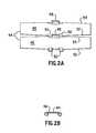
- FIG. 2 ais a diagrammatic plan view of two links of a preferred embodiment of a conveyor chain showing the preferred linkage
- FIG. 2 bis an end elevational view of the conveyor chain link shown in FIG. 2 a;
- FIG. 3is a diagrammatic plan view of a conveyor chain including a plurality of the links shown in FIGS. 2 a and 2 b showing the swiveling action of the links as the chain passes from a curved to a straight to a curved path of motion;
- FIG. 4is a diagrammatic plan view of a conveyor chain having adjacent objects thereon with the objects passing from curved to straight, and straight to curved, portions of the path, showing the objects becoming separated and accelerated;
- FIG. 5is a diagrammatic plan view of adjacent conveyor chains showing objects being guided from one chain to the other in the curve, being separated and accelerated by virtue of the higher speed of the second chain.
- FIG. 1shows a preferred embodiment of the present invention.
- the separator conveyor systemgenerally designated by the numeral 10 comprises a first conveyor 12 , a second conveyor 14 , and a third conveyor 15 .
- First conveyor 12comprises a feed section 16 , a first separation section 18 , and a first straightaway section 20 .
- Third conveyor 15comprises a second separation section 24 , and a second straightaway, or discharge, section 26 .
- Feed section 16merges into first separation section 18 at the line designated 28 .
- First separation section 18then merges into first straightaway section 20 at the line designated 30 .
- First straightaway section 20 of first conveyor 12merges into second separation section 24 of third conveyor 15 at the line designated 32 .
- Second separation section 24then merges into second straightaway section 26 at the line designated 34 .
- First separation section 18 , first straightaway section 20 , and second separation section 24comprise a separation zone.
- Second conveyor 14comprises a first separation section 38 merging into a first straightaway section 40 which merges into a second separation section 42 . As can be seen from FIG. 1, second conveyor 14 runs alongside first conveyor 12 and third conveyor 15 in the separation zone.
- First, second, and third conveyors 12 , 14 , and 15are preferably chain conveyors using links 44 of the type shown in FIGS. 2 a and 2 b.
- Each link 44comprises a generally planar top plate 46 having a center hinge eye 48 at its trailing end and a pair of complementary hinge eyes 50 at its leading end.
- the leading end of each link 44is pivotally connected to the trailing end of an adjacent leading link 44 by a first hinge pin (not shown).
- the trailing end of each link 44is pivotally connected to the leading end of an adjacent trailing link 44 by a second hinge pin (not shown).
- the leading and trailing edges 52 , 54 of each link 44are beveled to permit relative pivotal movement or sideflexing in the horizontal direction.
- Links 44may be fabricated of a suitable plastic or metal. Links of other shapes may be used as long as the desired flexing effect can be achieved. A suitably constructed elastomer belt could be used.
- a sideflexing chainis shown in FIG. 3 where the action of links 44 as they pass from a curve 56 to the right, to a straight section 58 , and into a curve 60 to the left can be seen.
- a plurality of links 44are joined in a manner already described.
- the links 44pivot so leading edge 52 of one link 44 essentially comes into contact with trailing edge 54 of the next adjacent link 44 at the inside of the curve.
- the gaps between the left ends of the links 44are at their widest.
- the linksare essentially symmetrically situated around the longitudinal axis with the gaps between adjacent links 44 at each end being essentially the same. In this area, the velocity has increased.
- FIG. 4where, again, the direction of movement of the chain is shown by the arrow 62 .
- objects 64 and 66may be separated or, as shown in FIG. 4, are essentially in contact.
- the ends of links 44have drawn apart, thereby separating objects 64 and 66 .
- the ends of links 44are further apart, thereby still further separating objects 64 and 66 .
- Feeder 68comprises a hopper 70 in which the objects to be handled are stocked in bulk, an elevator conveyor 72 , and a prefeeder 74 .
- the hopper 70is below the level of the separating conveyor.
- the elevator conveyor 72raises the objects from hopper 70 and deposits them in prefeeder 74 which then feeds them by vibration in a known manner onto the feed section 16 of first conveyor 12 .
- any known type of feeder to feed the objects to be handled to the conveyorcan be used.
- Conveyor 12includes an adjustable guide 76 which moves the objects to one margin of the chain. At the same time, the objects are marshaled into single file.
- Guide 76is adjustable to account for objects of varying shapes and sizes and may include fixtures (not shown) to discriminate the objects based on their orientation, and may turn the objects or reject some of them to fall back to hopper 70 .
- guide 76is illustrated as a pivotable bar, other embodiments are also contemplated, such as a pneumatic system, a robotic arm, or a fixed guide rail.
- First conveyor 12is driven by a motor and transmission 78 as is well-known in the art.
- Second conveyor 14is also driven by a known motor and transmission arrangement 80 , preferably at a higher speed than first conveyor 12 .
- Third conveyor 15is also driven by a known motor and transmission arrangement 81 , preferably at a higher speed than second conveyor 14 .
- the difference in speed between the first and second conveyors, and between the second and third conveyors,can easily be determined by those skilled in the art.
- Conveyors 12 , 14 , and 15are all driven in the direction shown by the arrow 82 .
- Conveyors 12 and 14are positioned such that adjacent edges of the chains align and the tops of the chains are essentially coplanar, thereby allowing for easy movement of articles from one chain to another.
- Suitably adjusted guides 84 and 86move the objects from first conveyor 12 to second conveyor 14 .
- Guides 84 and 86can be of similar construction as guide 76 .
- conveyors 14 and 15are positioned such that adjacent edges of the chains align and the tops of the chains are essentially coplanar, thereby allowing for easy movement of articles from one chain to another.
- Suitably adjusted guides 88 and 90move the objects from second conveyor 14 to third conveyor 15 .
- Guides 88 and 90can be of similar construction as guides 76 and/or guide 76 .
- Objects to be handled, stored in hopper 70are conveyed to prefeeder 74 by elevator conveyor 72 .
- Prefeeder 74then feeds the objects to feed section 16 of first conveyor 12 .
- any suitable feed apparatuscould be used to feed the objects to the conveyor 12 .
- the hopper-elevator conveyor-prefeeder arrangementis the presently preferred such device.
- the objectsare then guided by guide 76 into single file and onto second conveyor 14 by guides 84 and 86 .
- the objectsare separated and accelerated where chain 12 enters the curve at first separation section 38 and the ends of links 44 separate.
- the objectsare further separated and accelerated during the transfer to chain 14 and again where chain 14 leaves the curve and enters the first straightaway section 40 .
- Guides 88 and 90guide the objects from second chain 14 to third chain 15 at the second separation section 24 .
- the objectsare separated where chain 14 enters the curve, again where they transfer to chain 15 , and again where chain 15 exits the curve and enters the final straightaway 26 .
- the objectsthen pass through a machine 92 which affixes an adhesive label, a device 94 to press the label firmly in place, a reading station 96 which confirms the label is readable, and a blow off station 98 which takes the objects which do not have readable labels and deposits them into bin 100 .
- the objectsthen go on to the next processing stage schematically shown at 102 .
- Element 102may be a bin, or another conveyor, or any suitable continuation of the flow. Suitable sensors, whether photoelectric or mechanical, controllers, etc., all well-known in the art, may be used to control the operation of all or part of the system.
Landscapes
- Engineering & Computer Science (AREA)
- Mechanical Engineering (AREA)
- Attitude Control For Articles On Conveyors (AREA)
Abstract
Description
The present invention relates to an apparatus and method for separating adjacent objects on a conveyor. More particularly, the present invention is directed to a conveyor system which is capable of expanding a distance between two adjacent objects while moving the objects from one conveyor to another.
Separator conveyors are used to separate objects on a moving conveyor line. Usually, objects to be conveyed from one point to another in a manufacturing line are fed to a conveyor which moves the objects throughout the line. Generally, objects are fed in bulk to a conveyor line. The objects may be fed through a combining apparatus which aligns the objects in single file. Such a device is illustrated for example in U.S. Pat. No. 4,544,059. After the single file line of objects is formed, the objects tend to remain in line, against one another. Depending on the manufacturing line, a spacing may be desired between adjacent objects in order to carry out certain screening, inspection or other operations on each object. If the objects are too close together, an operation being performed on one object may interfere with an operation being performed on an adjacent object. Accordingly, it is important to control spacing of adjacent objects on the conveyor line.
In certain known separation conveyors, a mechanical device physically separates adjacent objects. For example, U.S. Pat. Nos. 1,689,247 and 1,463,527 disclose serpentine conveyor systems wherein a rotating drum having pins or fingers physically separate objects as they pass around the drum on the conveyor belt.
U.S. Pat. No. 3,386,558 discloses a feeder mechanism in which a device having fixed, radially extending arms is cam driven so that, as the device rotates, pneumatic suction cup gripping means at the ends of the arms travel along a path for removing folded carton blanks from a hopper and depositing them atop stacked containers moving along a conveyor belt. Rotationally eccentric movement is provided to the means which carries the fixed arms thereon.
U.S. Pat. No. 3,834,522 shows a transfer machine comprising a turret having a plurality of radially translatable carriages mounted thereon, which carriages are fitted with a suction cup for gripping a container. A cam track moves the carriages radially outwardly during rotation so as to enable the suction cups to grip the container at the unloading station, then retracts radially inwardly for transporting the container, and then moves radially outwardly to feed the container into the stacking device. The turret provides for intermittent movement between the stations to allow sufficient dwell time for the freshly printed containers to dry.
U.S. Pat. No. 4,369,875 discloses a slightly different arrangement wherein a series of pins is rotatingly maintained on a separate endless belt conveyor. The endless belt conveyor is driven at approximately the same rate as the feed conveyor. As objects pass the endless belt conveyor, the pins are inserted between adjacent objects thereby spreading the distance between those objects.
U.S. Pat. No. 4,726,876 discloses an apparatus for changing the spacing between articles of a moving array of discrete articles, and includes transfer means mounted for orbiting along a closed orbital path passing through a receiving zone and a discharge zone. The orbital radius of the transfer means is adjustable to provide an orbital radius in the discharge zone which is different from that in the receiving zone. The transfer means are maintained in fixed, equal angular distances between them along the orbital path whereby the orbital path distance between adjacent transfer means is different in the discharge zone from that in the receiving zone thereby resulting in a different spacing between adjacent articles in the discharge zone from that in the receiving zone. Two or more orbital spacer means may be utilized in tandem to provide the change in spacing in stages.
Other types of mechanically operated systems are also known. In each case, a device is generally engaged between adjacent objects to force the objects apart. There are several problems associated with these types of systems. Because the separator is an independently driven device, it must be controlled separately. The separate control system can be expensive and if the system breaks down, separation cannot be maintained. Yet further, the known techniques of separation require insertion of a device between adjacent objects. If the objects are fragile, they may be easily broken or damaged by insertion of the separating device. In addition, the physical touch may cause dirt or other unwanted contamination. The shape of the objects may render this approach unworkable.
The present invention is used to separate adjacent objects on a conveyor line so that certain manufacturing operations can be performed on the objects, while at the same time avoiding the problems associated with the prior known techniques of separation.
It is, therefore, an object of the present invention to provide a separating conveyor system which is free of the aforementioned and other such disadvantages wherein adjacent objects on a moving conveyor can be spaced from one another without the use of independent separating devices.
To achieve these and other advantages, the present invention is a conveyor arrangement, which accelerates and separates adjacent objects. The separation is accomplished with minimal contact and without interposing any separating means or devices. It requires little or no adjustment to work with a variety of shaped and sized objects.
The conveyor arrangement uses at least two so-called sideflexing conveyor chains arranged side-by-side similar to the conveyor chains shown in U.S. Pat. Nos. 4,823,939 and 5,779,027. This type of conveyor comprises flat topped links, which present an approximately continuous moving surface to the objects being conveyed.
The invention includes an area of the conveyor where two such chains are moving in a curve and are adjacent and parallel.
The objects to be conveyed and separated are introduced in single file on the first chain, and are riding near one margin of the chain. When the chain enters the curve, the ends of the links where the objects are riding accelerate and separate. Each conveyor section includes a plurality of links. Each link tapers from its mid-section toward each end. When the chain enters a curve the taper allows the spaces between links to close without interference on the side toward the center of curvature and to open on the opposite side. Objects are placed onto the idle end of the first conveyor, The guide rail crowds the objects toward one edge of the conveyor.
The objects are transferred from the first chain to the second chain in the curve, by a guide rail. They are now riding on the margin of the second conveyor. When the second conveyor leaves the curve and enters a straight, the link ends separate and accelerate, further separating the objects. The second chain is driven at a higher speed than the first chain. The linear velocity of the edge of the first chain at the outside of the curve is increased in consequence of the curvature and the linear velocity of the edge of the second chain at the inside of the curve is reduced in consequence of the curvature. The speeds of the chains are adjusted so the adjacent edges of the two conveyors along the curve are approximately the same. It is understood that “linear velocity” refers to the time rate of change of position of a body.
In an advantageous embodiment of the invention, the second chain enters a curve in the opposite direction, further accelerating and separating the objects. In this curve the objects are transferred to the third chain and the transfer and acceleration occurs, and when the third chain enters a straight-line section, the objects are again accelerated and separated. The process is same as transfer from first chain to second, and constitutes a second stage of the same process.
Other objects, advantages and novel features of the present invention will become apparent from the following detailed description of the invention when considered in conjunction with the accompanying drawings, wherein:
FIG. 1 is schematic top view of a preferred embodiment of the instant invention;
FIG. 2ais a diagrammatic plan view of two links of a preferred embodiment of a conveyor chain showing the preferred linkage;
FIG. 2bis an end elevational view of the conveyor chain link shown in FIG. 2a;
FIG. 3 is a diagrammatic plan view of a conveyor chain including a plurality of the links shown in FIGS. 2aand2bshowing the swiveling action of the links as the chain passes from a curved to a straight to a curved path of motion;
FIG. 4 is a diagrammatic plan view of a conveyor chain having adjacent objects thereon with the objects passing from curved to straight, and straight to curved, portions of the path, showing the objects becoming separated and accelerated; and
FIG. 5 is a diagrammatic plan view of adjacent conveyor chains showing objects being guided from one chain to the other in the curve, being separated and accelerated by virtue of the higher speed of the second chain.
Attention is first directed to FIG. 1 which shows a preferred embodiment of the present invention. The separator conveyor system generally designated by the numeral10 comprises afirst conveyor 12, asecond conveyor 14, and athird conveyor 15.First conveyor 12 comprises afeed section 16, afirst separation section 18, and a firststraightaway section 20.Third conveyor 15 comprises asecond separation section 24, and a second straightaway, or discharge,section 26.Feed section 16 merges intofirst separation section 18 at the line designated28.First separation section 18 then merges into firststraightaway section 20 at the line designated30. // Firststraightaway section 20 offirst conveyor 12 merges intosecond separation section 24 ofthird conveyor 15 at the line designated32.Second separation section 24 then merges into secondstraightaway section 26 at the line designated34.First separation section 18, firststraightaway section 20, andsecond separation section 24 comprise a separation zone.
First, second, andthird conveyors conveyors using links 44 of the type shown in FIGS. 2aand2b.Eachlink 44 comprises a generally planartop plate 46 having acenter hinge eye 48 at its trailing end and a pair ofcomplementary hinge eyes 50 at its leading end. The leading end of eachlink 44 is pivotally connected to the trailing end of an adjacent leadinglink 44 by a first hinge pin (not shown). The trailing end of eachlink 44 is pivotally connected to the leading end of an adjacent trailinglink 44 by a second hinge pin (not shown). The leading and trailingedges link 44 are beveled to permit relative pivotal movement or sideflexing in the horizontal direction. A sufficient number oflinks 44 is assembled into an endless sideflexing chain according to the desired size and configuration of the assembly in a manner which is well-known in the art.Links 44 may be fabricated of a suitable plastic or metal. Links of other shapes may be used as long as the desired flexing effect can be achieved. A suitably constructed elastomer belt could be used.
A sideflexing chain is shown in FIG. 3 where the action oflinks 44 as they pass from acurve 56 to the right, to astraight section 58, and into acurve 60 to the left can be seen. A plurality oflinks 44 are joined in a manner already described. In an area where the chain is rounding a curve to the right as shown at56, thelinks 44 pivot soleading edge 52 of onelink 44 essentially comes into contact with trailingedge 54 of the nextadjacent link 44 at the inside of the curve. The gaps between the left ends of thelinks 44 are at their widest. Atstraightaway section 58, the links are essentially symmetrically situated around the longitudinal axis with the gaps betweenadjacent links 44 at each end being essentially the same. In this area, the velocity has increased. When the chain is in a curve to the left as shown at60, the leading and trailingedges adjacent links 44 come into contact at the inside of the curve, the gaps between the right ends of thelinks 44 are at their widest, and the velocity is further increased. The direction of movement of the chain is shown byarrow 62.
Attention is now directed to FIG. 4 where, again, the direction of movement of the chain is shown by thearrow 62. Successive positions of two objects being conveyed are shown. In the first position, atcurve 56, objects64 and66 may be separated or, as shown in FIG. 4, are essentially in contact. Once the objects have moved out ofcurve 56 into the straight58, the ends oflinks 44 have drawn apart, thereby separatingobjects objects curve 60, the ends oflinks 44 are further apart, thereby still further separatingobjects
As can be seen from FIG. 5, objects64 and66 are shown with some separation between them atstraight section 65 offirst chain 12.Chain 12 enterscurve 67 and the objects acquire additional separation.Guide 84 moves the objects tochain 14 in the curve. As a consequence of the relative speeds ofchains Guide 86 may or may not be needed as determined by the speed of the machine and the shape and size of the parts.
Whenchain 14 moves fromcurve 71 to straight73, the objects are further separated. Depending on the nature of the objects, and the process to be applied to them, this may be an adequate separation. Otherwise, as in FIG. 1, the conveyor system has another stage of separation. The objects handled by the inventive system can be both rounded and irregular in shape, mandating the second stage.
Returning to FIG. 1, the objects to be handled are fed to feedsection 16 of thefirst conveyor 12 by a feeder generally designated by the numeral68.Feeder 68 comprises ahopper 70 in which the objects to be handled are stocked in bulk, anelevator conveyor 72, and aprefeeder 74. Thehopper 70 is below the level of the separating conveyor. Theelevator conveyor 72 raises the objects fromhopper 70 and deposits them inprefeeder 74 which then feeds them by vibration in a known manner onto thefeed section 16 offirst conveyor 12. As will be appreciated by those skilled in the art, any known type of feeder to feed the objects to be handled to the conveyor can be used.
Objects to be handled drop randomly fromprefeeder 74 on to thefeed section 16 offirst conveyor 12.Conveyor 12 includes anadjustable guide 76 which moves the objects to one margin of the chain. At the same time, the objects are marshaled into single file.Guide 76 is adjustable to account for objects of varying shapes and sizes and may include fixtures (not shown) to discriminate the objects based on their orientation, and may turn the objects or reject some of them to fall back tohopper 70. Althoughguide 76 is illustrated as a pivotable bar, other embodiments are also contemplated, such as a pneumatic system, a robotic arm, or a fixed guide rail.
The mode of operation of theconveyor system 10 will now be described with reference to FIG.1. Objects to be handled, stored inhopper 70, are conveyed to prefeeder74 byelevator conveyor 72.Prefeeder 74 then feeds the objects to feedsection 16 offirst conveyor 12. It is to be distinctly understood that any suitable feed apparatus could be used to feed the objects to theconveyor 12. The hopper-elevator conveyor-prefeeder arrangement is the presently preferred such device.
The objects are then guided byguide 76 into single file and ontosecond conveyor 14 byguides chain 12 enters the curve atfirst separation section 38 and the ends oflinks 44 separate. The objects are further separated and accelerated during the transfer tochain 14 and again wherechain 14 leaves the curve and enters the firststraightaway section 40.
In the embodiment shown, the objects then pass through amachine 92 which affixes an adhesive label, adevice 94 to press the label firmly in place, a readingstation 96 which confirms the label is readable, and a blow offstation 98 which takes the objects which do not have readable labels and deposits them intobin 100. The objects then go on to the next processing stage schematically shown at102.Element 102 may be a bin, or another conveyor, or any suitable continuation of the flow. Suitable sensors, whether photoelectric or mechanical, controllers, etc., all well-known in the art, may be used to control the operation of all or part of the system.
The foregoing disclosure has been set forth merely to illustrate the invention and is not intended to be limiting. Since modifications of the disclosed embodiments incorporating the spirit and substance of the invention may occur to persons skilled in the art, the invention should be construed to include everything within the scope of the appended claims and equivalents thereof.
Claims (20)
1. A conveyor arrangement for separating objects, comprising:
at least two sideways flexing conveyors arranged parallel and side-by-side, and which run for at least part of their length in a curved path;
wherein, at a point in the curved path, the linear velocity at the side of the first conveyor which adjoins a side of the second conveyor is increased in consequence of the curvature and the linear velocity at said side of the second of said two conveyors is reduced in consequence of the curvature; and
at least one guide that guides objects to enable the objects to transfer from the first of said two conveyors to the second of said two conveyors at said point;
wherein said second conveyor is run at a higher speed than said first conveyor;
whereby, the speed of the second conveyor is equal to or greater than the speed of the first conveyor at the transfer point.
2. A conveyor arrangement as defined in claim1, wherein at least one of said conveyors comprises an endless chain traveling at a pitch line velocity, said chain comprising links joined to each other such that said chain is able to flex when traveling along a curved path, each of said links having a shape such that the ends of the links toward the center of curvature of said curved path move closer together and travel at a slower velocity than the pitch line velocity of the chain, and the ends of the links away from the center of curvature of said curved path are spread apart and travel at a faster velocity than the pitch line velocity of the chain.
3. A conveyor arrangement as defined in claim2, wherein said links are flexibly joined at a central portion thereof and taper in width from the center thereof to the ends, whereby when the links move in a curved path, facing sides of adjacent links closer to the center of curvature move together and facing sides of adjacent links away from the center of curvature move apart.
4. A conveyor arrangement as defined in claim2, wherein top surfaces of said links are planar.
5. A conveyor arrangement as defined in claim1, wherein said conveyors are driven by separate drive motors.
6. A conveyor arrangement as defined in claim1, wherein said conveyors are driven by a single motor, with the second conveyor being driven faster than the first conveyor.
7. A conveyor arrangement as defined in claim1, further comprising a third conveyor;
wherein the first and second conveyors are parallel and include a first curved section in at least part of their path, and the second and third conveyors are parallel and include a second curved section in at least part of their path, said second curved section being a reverse curve relative to said first curved section;
wherein, at a point in the second curved section, the linear velocity at the side of the second conveyor which adjoins a side of the third conveyor is increased in consequence of the curvature and the linear velocity at said side of the third conveyor is reduced in consequence of the curvature; and
at least one guide that guides objects to enable the objects to transfer from the second conveyor to the third conveyor at said point in the second curved section.
8. A conveyor arrangement as defined in claim7, comprising a first straight portion, a first curved portion, and second straight portion, a second straight portion, a second curved portion, and a third straight portion; wherein said first straight portion is an infeed zone of said first conveyor, said first curved portion comprises said first and second conveyors, said second curved portion comprises said second and third conveyors, and said third straight portion is a discharge zone of said third conveyor.
9. A conveyor arrangement according to claim1, further comprising a supply hopper and a feed conveyor to feed a plurality of objects from said hopper onto said first conveyor.
10. A conveyor arrangement as defined in claim1, wherein top surfaces of adjacent conveyors are coplanar.
11. A conveyor arrangement as defined in claim10, wherein the plane of the top surfaces is inclined to one side.
12. A separator conveyor for simultaneously conveying and separating objects, comprising:
a separating and accelerating conveyor comprising at least a pair of adjacent conveyor belts, each conveyor belt comprising a plurality of links having a shape such that respective ends of adjacent links on each conveyor have a variable gap there between, and each conveyor belt having an edge adjacent an edge of the other conveyor belt;
at least one guide device for guiding objects from one conveyor to the other;
a motor control system for independently driving the separating conveyor belts at different speeds;
wherein the plurality of links comprises an arrangement of links wherein each link is pivotable about a center region thereof to vary the adjustable gap between adjacent link edges thereby separating and accelerating objects guided from one conveyor to the other.
13. A separator conveyor according to claim12 wherein the pair of conveyor belts has a curved radius along a horizontal plane.
14. A separator conveyor according to claim13, wherein the links are pivoted about the mid-section by movement around the curved conveyor radius.
15. A separator conveyor according to claim14, wherein two sets of conveyor belts are provided and are arranged to transfer objects along a length thereof.
16. A separator conveyor according to claim12, further comprising a feed conveyor that aligns a plurality of objects into a single file and feeds the objects to the separator and accelerating conveyor.
17. A separator conveyor according to claim16, wherein said feed conveyor further comprises a guide arrangement to guide the plurality of objects into the single file orientation.
18. A method for separating objects on a conveyor system comprising at least two sideways flexing conveyors arranged parallel and side-by-side, traveling at least partly in a curved path, and having coplanar conveying surfaces, said method comprising:
guiding the plurality of objects into a single file orientation on the first of said at least two conveyors; and
causing the objects to transfer from said first conveyor to the second of said at least two conveyors during travel along said curved path.
19. A method as defined in claim18, further comprising driving said second conveyor at a higher speed than said first conveyor.
20. A method as defined in claim19, wherein the linear velocity of each of said conveyors at its edge along the outside of the curve is approximately equal to the linear velocity of the adjacent conveyor at its edge along the inside of the curve.
Priority Applications (1)
| Application Number | Priority Date | Filing Date | Title |
|---|---|---|---|
| US09/482,355US6273238B1 (en) | 2000-01-14 | 2000-01-14 | Apparatus and method for separating adjacent objects on a conveyor |
Applications Claiming Priority (1)
| Application Number | Priority Date | Filing Date | Title |
|---|---|---|---|
| US09/482,355US6273238B1 (en) | 2000-01-14 | 2000-01-14 | Apparatus and method for separating adjacent objects on a conveyor |
Publications (1)
| Publication Number | Publication Date |
|---|---|
| US6273238B1true US6273238B1 (en) | 2001-08-14 |
Family
ID=23915716
Family Applications (1)
| Application Number | Title | Priority Date | Filing Date |
|---|---|---|---|
| US09/482,355Expired - Fee RelatedUS6273238B1 (en) | 2000-01-14 | 2000-01-14 | Apparatus and method for separating adjacent objects on a conveyor |
Country Status (1)
| Country | Link |
|---|---|
| US (1) | US6273238B1 (en) |
Cited By (12)
| Publication number | Priority date | Publication date | Assignee | Title |
|---|---|---|---|---|
| US6563901B2 (en) | 2001-10-05 | 2003-05-13 | Donald R. Wooldridge | Multi-head counting system with size discrimination |
| US20040007438A1 (en)* | 2002-06-24 | 2004-01-15 | John Baranowski | Dispensing systems and methods |
| US20040007444A1 (en)* | 2002-06-24 | 2004-01-15 | John Baranowski | Dispensers and methods of dispensing items |
| US20040016765A1 (en)* | 2002-06-24 | 2004-01-29 | John Baranowski | Control systems and methods of dispensing items |
| US20040053449A1 (en)* | 2002-09-13 | 2004-03-18 | Chich-Shang Chang | Method for producing plastic active panel displays |
| US20040134926A1 (en)* | 2002-06-24 | 2004-07-15 | John Baranowski | Dispensing systems and methods |
| US20040134758A1 (en)* | 2002-06-24 | 2004-07-15 | John Baranowski | Dispensers and methods of dispensing items |
| US20040148056A1 (en)* | 2002-06-24 | 2004-07-29 | John Baranowski | Control systems and methods of dispensing items |
| US20040164088A1 (en)* | 2002-06-24 | 2004-08-26 | John Baranowski | Dispensing and diversion systems and methods |
| US7036679B2 (en) | 2002-06-24 | 2006-05-02 | John Baranowski | Dispensing and diversion systems and methods |
| CN113562401A (en)* | 2021-07-23 | 2021-10-29 | 杭州海康机器人技术有限公司 | Control target object transmission method, device, system, terminal and storage medium |
| US20220289498A1 (en)* | 2021-03-10 | 2022-09-15 | Fameccanica.Data S.P.A | Apparatus and method for varying the pitch between moving articles |
Citations (14)
| Publication number | Priority date | Publication date | Assignee | Title |
|---|---|---|---|---|
| US1463527A (en) | 1922-07-25 | 1923-07-31 | Henry L Guenther | Can feeding and timing device |
| US1689247A (en) | 1926-09-17 | 1928-10-30 | Max Ams Machine Co | Conveying and accelerating device |
| US1820562A (en) | 1928-06-15 | 1931-08-25 | Henry L Guenther | Accelerating can feed |
| US3717236A (en) | 1970-01-29 | 1973-02-20 | Molins Ltd | Conveying apparatus |
| US3847273A (en) | 1973-04-02 | 1974-11-12 | Scott Paper Co | Turning device for flexible web product |
| US4456117A (en)* | 1981-11-23 | 1984-06-26 | Lasalle Machine Tool, Inc. | Conveyor with slow down section |
| US4544059A (en) | 1981-07-03 | 1985-10-01 | De Forenede Bryggerier A/S | Apparatus for combining several rows of bottles or similar objects on an inlet conveyor to a single row on an outlet conveyor |
| US4823939A (en) | 1985-10-31 | 1989-04-25 | Rexnord Kette Gmbh & Co Kg | Curved path chain conveyor |
| US5076422A (en) | 1990-08-29 | 1991-12-31 | Tekno Incorporated | Side-flexing chain with wheels |
| US5692594A (en)* | 1994-10-21 | 1997-12-02 | Inmara Ag | Transport apparatus |
| US5779027A (en) | 1996-02-14 | 1998-07-14 | Rexnord Corporation | Sideflexing conveyor including lubrication inserts |
| US5782332A (en) | 1994-08-19 | 1998-07-21 | Sasib Packaging Italia S.R.L. | Device and corresponding method for grouping together random product flows into a single path according to a pre-established and adjustable rate of advance |
| US5878865A (en)* | 1994-02-15 | 1999-03-09 | Molins Plc | Variable speed conveying apparatus |
| US6098785A (en)* | 1997-06-20 | 2000-08-08 | Klockner Hansel Tevopharm B.V. | Conveyor device for accelerating a series of products |
- 2000
- 2000-01-14USUS09/482,355patent/US6273238B1/ennot_activeExpired - Fee Related
Patent Citations (14)
| Publication number | Priority date | Publication date | Assignee | Title |
|---|---|---|---|---|
| US1463527A (en) | 1922-07-25 | 1923-07-31 | Henry L Guenther | Can feeding and timing device |
| US1689247A (en) | 1926-09-17 | 1928-10-30 | Max Ams Machine Co | Conveying and accelerating device |
| US1820562A (en) | 1928-06-15 | 1931-08-25 | Henry L Guenther | Accelerating can feed |
| US3717236A (en) | 1970-01-29 | 1973-02-20 | Molins Ltd | Conveying apparatus |
| US3847273A (en) | 1973-04-02 | 1974-11-12 | Scott Paper Co | Turning device for flexible web product |
| US4544059A (en) | 1981-07-03 | 1985-10-01 | De Forenede Bryggerier A/S | Apparatus for combining several rows of bottles or similar objects on an inlet conveyor to a single row on an outlet conveyor |
| US4456117A (en)* | 1981-11-23 | 1984-06-26 | Lasalle Machine Tool, Inc. | Conveyor with slow down section |
| US4823939A (en) | 1985-10-31 | 1989-04-25 | Rexnord Kette Gmbh & Co Kg | Curved path chain conveyor |
| US5076422A (en) | 1990-08-29 | 1991-12-31 | Tekno Incorporated | Side-flexing chain with wheels |
| US5878865A (en)* | 1994-02-15 | 1999-03-09 | Molins Plc | Variable speed conveying apparatus |
| US5782332A (en) | 1994-08-19 | 1998-07-21 | Sasib Packaging Italia S.R.L. | Device and corresponding method for grouping together random product flows into a single path according to a pre-established and adjustable rate of advance |
| US5692594A (en)* | 1994-10-21 | 1997-12-02 | Inmara Ag | Transport apparatus |
| US5779027A (en) | 1996-02-14 | 1998-07-14 | Rexnord Corporation | Sideflexing conveyor including lubrication inserts |
| US6098785A (en)* | 1997-06-20 | 2000-08-08 | Klockner Hansel Tevopharm B.V. | Conveyor device for accelerating a series of products |
Cited By (19)
| Publication number | Priority date | Publication date | Assignee | Title |
|---|---|---|---|---|
| US6563901B2 (en) | 2001-10-05 | 2003-05-13 | Donald R. Wooldridge | Multi-head counting system with size discrimination |
| US7099741B2 (en) | 2002-06-24 | 2006-08-29 | Campbell Soup Company | Control systems and methods of dispensing items |
| US7063215B2 (en) | 2002-06-24 | 2006-06-20 | Campbell Soup Company | Control systems and methods of dispensing items |
| US20040016765A1 (en)* | 2002-06-24 | 2004-01-29 | John Baranowski | Control systems and methods of dispensing items |
| US7152756B2 (en) | 2002-06-24 | 2006-12-26 | Campbell Soup Company | Dispensing systems and methods |
| US20040134926A1 (en)* | 2002-06-24 | 2004-07-15 | John Baranowski | Dispensing systems and methods |
| US20040134758A1 (en)* | 2002-06-24 | 2004-07-15 | John Baranowski | Dispensers and methods of dispensing items |
| US20040148056A1 (en)* | 2002-06-24 | 2004-07-29 | John Baranowski | Control systems and methods of dispensing items |
| US20040164088A1 (en)* | 2002-06-24 | 2004-08-26 | John Baranowski | Dispensing and diversion systems and methods |
| US20040007444A1 (en)* | 2002-06-24 | 2004-01-15 | John Baranowski | Dispensers and methods of dispensing items |
| US6993884B2 (en) | 2002-06-24 | 2006-02-07 | Campell Soup Company | Dispensing systems and methods |
| US7036679B2 (en) | 2002-06-24 | 2006-05-02 | John Baranowski | Dispensing and diversion systems and methods |
| US20040007438A1 (en)* | 2002-06-24 | 2004-01-15 | John Baranowski | Dispensing systems and methods |
| US7128204B2 (en) | 2002-06-24 | 2006-10-31 | Campbell Soup Company | Dispensers and methods of dispensing items |
| US7128203B2 (en) | 2002-06-24 | 2006-10-31 | Campbell Soup Company | Dispensers and methods of dispensing items |
| US20040053449A1 (en)* | 2002-09-13 | 2004-03-18 | Chich-Shang Chang | Method for producing plastic active panel displays |
| US20220289498A1 (en)* | 2021-03-10 | 2022-09-15 | Fameccanica.Data S.P.A | Apparatus and method for varying the pitch between moving articles |
| US11905123B2 (en)* | 2021-03-10 | 2024-02-20 | Fameccanica.Data S.P.A. | Apparatus and method for varying the pitch between moving articles |
| CN113562401A (en)* | 2021-07-23 | 2021-10-29 | 杭州海康机器人技术有限公司 | Control target object transmission method, device, system, terminal and storage medium |
Similar Documents
| Publication | Publication Date | Title |
|---|---|---|
| EP0056946B2 (en) | An arrangement for the feeding of objects | |
| KR100454350B1 (en) | Packing machine for multi-packs | |
| KR0136651B1 (en) | Apparatus for transferring a stream of receptacles supplied on one track in a row to a plurality of discharging conveying tracks | |
| US4527792A (en) | Apparatus for changing the direction of motion of letters and similar rectangular pieces of mail | |
| US6273238B1 (en) | Apparatus and method for separating adjacent objects on a conveyor | |
| EP2041006B1 (en) | System and method for turning and separating product packages | |
| US9352507B2 (en) | Separator device for preforms | |
| EP2195265B1 (en) | Transfer device metering apparatus and methods | |
| CA1180361A (en) | High speed transport system for newspapers and the like | |
| US7494003B2 (en) | Outfeed mechanism for starwheel type glass inspection machine | |
| EP0894750B1 (en) | Method and unit for combined transfer-turnover of packets of cigarettes | |
| US6240707B1 (en) | Carton opening apparatus | |
| US4424965A (en) | High speed transport system for newspapers and the like | |
| US6669006B2 (en) | Method and device for conveying reams of paper | |
| KR920009504A (en) | Collating apparatus | |
| US4482139A (en) | Transport and separating apparatus for folded printed matter | |
| EP0608103B1 (en) | Packaging machine with flight bar carton conveying system | |
| US4081078A (en) | Article sorting apparatus | |
| US11905123B2 (en) | Apparatus and method for varying the pitch between moving articles | |
| WO2022159465A1 (en) | Conveyor belt for transporting conveyed material and packaging line of a packaging system comprising such a conveyor belt | |
| US4925006A (en) | Conveyor apparatus having means for a shock-free article acceleration | |
| JP2000062945A (en) | Conveyance device | |
| JPH10501511A (en) | Method and apparatus for transporting print streams | |
| US6705607B2 (en) | Device for transporting printed products | |
| KR102814931B1 (en) | Sheet handler |
Legal Events
| Date | Code | Title | Description |
|---|---|---|---|
| AS | Assignment | Owner name:BATCHING SYSTEMS, INC., MARYLAND Free format text:ASSIGNMENT OF ASSIGNORS INTEREST;ASSIGNOR:WOOLDRIDGE, DONALD;REEL/FRAME:010543/0418 Effective date:20000112 | |
| FPAY | Fee payment | Year of fee payment:4 | |
| SULP | Surcharge for late payment | ||
| REMI | Maintenance fee reminder mailed | ||
| AS | Assignment | Owner name:DONALD WOOLDRIDGE AND BEVERLY WOOLDRIDGE, MARYLAND Free format text:SECURITY INTEREST;ASSIGNOR:BATCHING SYSTEMS, INC.;REEL/FRAME:016987/0374 Effective date:20050316 | |
| AS | Assignment | Owner name:DIAMOND MACHINE WERKS, INC., ILLINOIS Free format text:ASSIGNMENT OF ASSIGNORS INTEREST;ASSIGNOR:BATCHING SYSTEMS, INC.;REEL/FRAME:017696/0503 Effective date:20060308 | |
| REMI | Maintenance fee reminder mailed | ||
| LAPS | Lapse for failure to pay maintenance fees | ||
| STCH | Information on status: patent discontinuation | Free format text:PATENT EXPIRED DUE TO NONPAYMENT OF MAINTENANCE FEES UNDER 37 CFR 1.362 | |
| FP | Lapsed due to failure to pay maintenance fee | Effective date:20090814 |