US6273066B1 - Fuel injection for an internal combustion engine - Google Patents
Fuel injection for an internal combustion engineDownload PDFInfo
- Publication number
- US6273066B1 US6273066B1US09/558,833US55883300AUS6273066B1US 6273066 B1US6273066 B1US 6273066B1US 55883300 AUS55883300 AUS 55883300AUS 6273066 B1US6273066 B1US 6273066B1
- Authority
- US
- United States
- Prior art keywords
- fuel
- injector
- pressure regulating
- pressure
- valve
- Prior art date
- Legal status (The legal status is an assumption and is not a legal conclusion. Google has not performed a legal analysis and makes no representation as to the accuracy of the status listed.)
- Expired - Fee Related
Links
Images


Classifications
- F—MECHANICAL ENGINEERING; LIGHTING; HEATING; WEAPONS; BLASTING
- F02—COMBUSTION ENGINES; HOT-GAS OR COMBUSTION-PRODUCT ENGINE PLANTS
- F02M—SUPPLYING COMBUSTION ENGINES IN GENERAL WITH COMBUSTIBLE MIXTURES OR CONSTITUENTS THEREOF
- F02M63/00—Other fuel-injection apparatus having pertinent characteristics not provided for in groups F02M39/00 - F02M57/00 or F02M67/00; Details, component parts, or accessories of fuel-injection apparatus, not provided for in, or of interest apart from, the apparatus of groups F02M39/00 - F02M61/00 or F02M67/00; Combination of fuel pump with other devices, e.g. lubricating oil pump
- F02M63/0012—Valves
- F02M63/0014—Valves characterised by the valve actuating means
- F02M63/0028—Valves characterised by the valve actuating means hydraulic
- F02M63/0029—Valves characterised by the valve actuating means hydraulic using a pilot valve controlling a hydraulic chamber
- F—MECHANICAL ENGINEERING; LIGHTING; HEATING; WEAPONS; BLASTING
- F02—COMBUSTION ENGINES; HOT-GAS OR COMBUSTION-PRODUCT ENGINE PLANTS
- F02M—SUPPLYING COMBUSTION ENGINES IN GENERAL WITH COMBUSTIBLE MIXTURES OR CONSTITUENTS THEREOF
- F02M45/00—Fuel-injection apparatus characterised by having a cyclic delivery of specific time/pressure or time/quantity relationship
- F02M45/12—Fuel-injection apparatus characterised by having a cyclic delivery of specific time/pressure or time/quantity relationship providing a continuous cyclic delivery with variable pressure
- F—MECHANICAL ENGINEERING; LIGHTING; HEATING; WEAPONS; BLASTING
- F02—COMBUSTION ENGINES; HOT-GAS OR COMBUSTION-PRODUCT ENGINE PLANTS
- F02M—SUPPLYING COMBUSTION ENGINES IN GENERAL WITH COMBUSTIBLE MIXTURES OR CONSTITUENTS THEREOF
- F02M47/00—Fuel-injection apparatus operated cyclically with fuel-injection valves actuated by fluid pressure
- F02M47/02—Fuel-injection apparatus operated cyclically with fuel-injection valves actuated by fluid pressure of accumulator-injector type, i.e. having fuel pressure of accumulator tending to open, and fuel pressure in other chamber tending to close, injection valves and having means for periodically releasing that closing pressure
- F02M47/027—Electrically actuated valves draining the chamber to release the closing pressure
- F—MECHANICAL ENGINEERING; LIGHTING; HEATING; WEAPONS; BLASTING
- F02—COMBUSTION ENGINES; HOT-GAS OR COMBUSTION-PRODUCT ENGINE PLANTS
- F02M—SUPPLYING COMBUSTION ENGINES IN GENERAL WITH COMBUSTIBLE MIXTURES OR CONSTITUENTS THEREOF
- F02M59/00—Pumps specially adapted for fuel-injection and not provided for in groups F02M39/00 -F02M57/00, e.g. rotary cylinder-block type of pumps
- F02M59/44—Details, components parts, or accessories not provided for in, or of interest apart from, the apparatus of groups F02M59/02 - F02M59/42; Pumps having transducers, e.g. to measure displacement of pump rack or piston
- F02M59/46—Valves
- F—MECHANICAL ENGINEERING; LIGHTING; HEATING; WEAPONS; BLASTING
- F02—COMBUSTION ENGINES; HOT-GAS OR COMBUSTION-PRODUCT ENGINE PLANTS
- F02M—SUPPLYING COMBUSTION ENGINES IN GENERAL WITH COMBUSTIBLE MIXTURES OR CONSTITUENTS THEREOF
- F02M63/00—Other fuel-injection apparatus having pertinent characteristics not provided for in groups F02M39/00 - F02M57/00 or F02M67/00; Details, component parts, or accessories of fuel-injection apparatus, not provided for in, or of interest apart from, the apparatus of groups F02M39/00 - F02M61/00 or F02M67/00; Combination of fuel pump with other devices, e.g. lubricating oil pump
- F02M63/0003—Fuel-injection apparatus having a cyclically-operated valve for connecting a pressure source, e.g. constant pressure pump or accumulator, to an injection valve held closed mechanically, e.g. by springs, and automatically opened by fuel pressure
- F02M63/0005—Fuel-injection apparatus having a cyclically-operated valve for connecting a pressure source, e.g. constant pressure pump or accumulator, to an injection valve held closed mechanically, e.g. by springs, and automatically opened by fuel pressure using valves actuated by fluid pressure
- F—MECHANICAL ENGINEERING; LIGHTING; HEATING; WEAPONS; BLASTING
- F02—COMBUSTION ENGINES; HOT-GAS OR COMBUSTION-PRODUCT ENGINE PLANTS
- F02M—SUPPLYING COMBUSTION ENGINES IN GENERAL WITH COMBUSTIBLE MIXTURES OR CONSTITUENTS THEREOF
- F02M63/00—Other fuel-injection apparatus having pertinent characteristics not provided for in groups F02M39/00 - F02M57/00 or F02M67/00; Details, component parts, or accessories of fuel-injection apparatus, not provided for in, or of interest apart from, the apparatus of groups F02M39/00 - F02M61/00 or F02M67/00; Combination of fuel pump with other devices, e.g. lubricating oil pump
- F02M63/0003—Fuel-injection apparatus having a cyclically-operated valve for connecting a pressure source, e.g. constant pressure pump or accumulator, to an injection valve held closed mechanically, e.g. by springs, and automatically opened by fuel pressure
- F02M63/0007—Fuel-injection apparatus having a cyclically-operated valve for connecting a pressure source, e.g. constant pressure pump or accumulator, to an injection valve held closed mechanically, e.g. by springs, and automatically opened by fuel pressure using electrically actuated valves
- F—MECHANICAL ENGINEERING; LIGHTING; HEATING; WEAPONS; BLASTING
- F02—COMBUSTION ENGINES; HOT-GAS OR COMBUSTION-PRODUCT ENGINE PLANTS
- F02M—SUPPLYING COMBUSTION ENGINES IN GENERAL WITH COMBUSTIBLE MIXTURES OR CONSTITUENTS THEREOF
- F02M63/00—Other fuel-injection apparatus having pertinent characteristics not provided for in groups F02M39/00 - F02M57/00 or F02M67/00; Details, component parts, or accessories of fuel-injection apparatus, not provided for in, or of interest apart from, the apparatus of groups F02M39/00 - F02M61/00 or F02M67/00; Combination of fuel pump with other devices, e.g. lubricating oil pump
- F02M63/0012—Valves
- F02M63/0031—Valves characterized by the type of valves, e.g. special valve member details, valve seat details, valve housing details
- F02M63/0045—Three-way valves
- F—MECHANICAL ENGINEERING; LIGHTING; HEATING; WEAPONS; BLASTING
- F02—COMBUSTION ENGINES; HOT-GAS OR COMBUSTION-PRODUCT ENGINE PLANTS
- F02M—SUPPLYING COMBUSTION ENGINES IN GENERAL WITH COMBUSTIBLE MIXTURES OR CONSTITUENTS THEREOF
- F02M2200/00—Details of fuel-injection apparatus, not otherwise provided for
- F02M2200/21—Fuel-injection apparatus with piezoelectric or magnetostrictive elements
- F—MECHANICAL ENGINEERING; LIGHTING; HEATING; WEAPONS; BLASTING
- F02—COMBUSTION ENGINES; HOT-GAS OR COMBUSTION-PRODUCT ENGINE PLANTS
- F02M—SUPPLYING COMBUSTION ENGINES IN GENERAL WITH COMBUSTIBLE MIXTURES OR CONSTITUENTS THEREOF
- F02M45/00—Fuel-injection apparatus characterised by having a cyclic delivery of specific time/pressure or time/quantity relationship
- F02M45/02—Fuel-injection apparatus characterised by having a cyclic delivery of specific time/pressure or time/quantity relationship with each cyclic delivery being separated into two or more parts
- F—MECHANICAL ENGINEERING; LIGHTING; HEATING; WEAPONS; BLASTING
- F02—COMBUSTION ENGINES; HOT-GAS OR COMBUSTION-PRODUCT ENGINE PLANTS
- F02M—SUPPLYING COMBUSTION ENGINES IN GENERAL WITH COMBUSTIBLE MIXTURES OR CONSTITUENTS THEREOF
- F02M59/00—Pumps specially adapted for fuel-injection and not provided for in groups F02M39/00 -F02M57/00, e.g. rotary cylinder-block type of pumps
- F02M59/44—Details, components parts, or accessories not provided for in, or of interest apart from, the apparatus of groups F02M59/02 - F02M59/42; Pumps having transducers, e.g. to measure displacement of pump rack or piston
- F02M59/46—Valves
- F02M59/466—Electrically operated valves, e.g. using electromagnetic or piezoelectric operating means
- F02M59/468—Electrically operated valves, e.g. using electromagnetic or piezoelectric operating means using piezoelectric operating means
- F—MECHANICAL ENGINEERING; LIGHTING; HEATING; WEAPONS; BLASTING
- F02—COMBUSTION ENGINES; HOT-GAS OR COMBUSTION-PRODUCT ENGINE PLANTS
- F02M—SUPPLYING COMBUSTION ENGINES IN GENERAL WITH COMBUSTIBLE MIXTURES OR CONSTITUENTS THEREOF
- F02M63/00—Other fuel-injection apparatus having pertinent characteristics not provided for in groups F02M39/00 - F02M57/00 or F02M67/00; Details, component parts, or accessories of fuel-injection apparatus, not provided for in, or of interest apart from, the apparatus of groups F02M39/00 - F02M61/00 or F02M67/00; Combination of fuel pump with other devices, e.g. lubricating oil pump
- F02M63/02—Fuel-injection apparatus having several injectors fed by a common pumping element, or having several pumping elements feeding a common injector; Fuel-injection apparatus having provisions for cutting-out pumps, pumping elements, or injectors; Fuel-injection apparatus having provisions for variably interconnecting pumping elements and injectors alternatively
- F02M63/0205—Fuel-injection apparatus having several injectors fed by a common pumping element, or having several pumping elements feeding a common injector; Fuel-injection apparatus having provisions for cutting-out pumps, pumping elements, or injectors; Fuel-injection apparatus having provisions for variably interconnecting pumping elements and injectors alternatively for cutting-out pumps or injectors in case of abnormal operation of the engine or the injection apparatus, e.g. over-speed, break-down of fuel pumps or injectors ; for cutting-out pumps for stopping the engine
- F02M63/0215—Fuel-injection apparatus having several injectors fed by a common pumping element, or having several pumping elements feeding a common injector; Fuel-injection apparatus having provisions for cutting-out pumps, pumping elements, or injectors; Fuel-injection apparatus having provisions for variably interconnecting pumping elements and injectors alternatively for cutting-out pumps or injectors in case of abnormal operation of the engine or the injection apparatus, e.g. over-speed, break-down of fuel pumps or injectors ; for cutting-out pumps for stopping the engine by draining or closing fuel conduits
- F—MECHANICAL ENGINEERING; LIGHTING; HEATING; WEAPONS; BLASTING
- F02—COMBUSTION ENGINES; HOT-GAS OR COMBUSTION-PRODUCT ENGINE PLANTS
- F02M—SUPPLYING COMBUSTION ENGINES IN GENERAL WITH COMBUSTIBLE MIXTURES OR CONSTITUENTS THEREOF
- F02M63/00—Other fuel-injection apparatus having pertinent characteristics not provided for in groups F02M39/00 - F02M57/00 or F02M67/00; Details, component parts, or accessories of fuel-injection apparatus, not provided for in, or of interest apart from, the apparatus of groups F02M39/00 - F02M61/00 or F02M67/00; Combination of fuel pump with other devices, e.g. lubricating oil pump
- F02M63/02—Fuel-injection apparatus having several injectors fed by a common pumping element, or having several pumping elements feeding a common injector; Fuel-injection apparatus having provisions for cutting-out pumps, pumping elements, or injectors; Fuel-injection apparatus having provisions for variably interconnecting pumping elements and injectors alternatively
- F02M63/0225—Fuel-injection apparatus having a common rail feeding several injectors ; Means for varying pressure in common rails; Pumps feeding common rails
Definitions
- the inventionrelates to a fuel injection system for an internal combustion engine with a high-pressure pump for pumping the fuel into a high-pressure reservoir and with at least one injector connected to the high-pressure reservoir by a feed line. Operation of the fuel injector is controlled by a solenoid valve with fuel passages which are connected to the feed line, one of the fuel passages leads to an injection nozzle and another fuel passage leads to a control space which is delimited by a control piston interacting with a nozzle needle of the injection nozzle and which is connected to a low pressure return past a solenoid valve which controls the injector. Furthermore a pressure regulating valve is provided in the path of fuel flow between the high-pressure reservoir and the injection nozzle and has a passage used to direct fuel flow from the high-pressure reservoir to the injection nozzle.
- DE 196 12 738 A1has disclosed a fuel injection system of this general type with an injector controlled by a solenoid valve.
- the injectorcontains a pressure control valve which is combined with the control piston and controls the flow connection between the high-pressure reservoir and the injection nozzle in a manner dependent on the solenoid valve, such that the flow connection is interrupted between the injection processes but opened up during each injection process.
- the fuel feed passage leading to the pressure space about the nozzle and needle valveis always connected to a restricted return line located on the low-pressure side.
- a very low pressureacts on the needle seat of the injection nozzle.
- the pressure at the needle seatrises.
- injectionstarts.
- the flow connection between the high-pressure reservoir and the needle seatis again closed and the pressure at the nozzle needle of the injection nozzle decreases rapidly. Once the pressure falls below the injector valve's opening pressure, the injection nozzle closes.
- the main object of the inventionis to provide regulation and control of a fuel injection system which, in addition to post-injection, also make it possible to influence the opening of the injection valve at different pressures.
- the high pressure of the reservoireffectively operates ahead of the injector's needle seat even after the closing of the first solenoid valve, which is arranged to control the connection between the control space and the low pressure fuel return. This makes it possible to achieve a subsequent post-injection under influence of high injection pressure.
- Another advantageous feature of the inventionresults from providing opening control of the injector's nozzle needle as initiated by activating the first solenoid valve, irrespective of the particular fuel pressure value.
- a pilot injectioncan be carried out by means of a restricted pressure connection located in an intermediate position between the second and the third operative positions of a pressure regulating and control piston.
- Another advantageis the possibility of selecting the position of the pressure regulating valve by a solenoid activated valve, which is used either as a component integrated into the injector or as a retrofitted kit inserted into an exposed feed line.
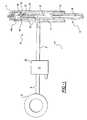
- FIG. 1shows a fuel injection system with a pressure regulating valve provided in the fuel feed line which includes a solenoid activated valve;
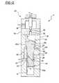
- FIG. 2shows an elevational sectioned view of the pressure regulating valve
- FIGS. 3 a-dshow elevational sectioned views of the pressure regulating valve with its pressure regulation piston in four different operational positions
- FIG. 4shows a plot of a variation in pressure with time for system operation and revealing four phases of operation.
- a fuel injection system 1is shown in FIG. 1 comprising a high-pressure reservoir 2 , a fuel feed line 3 , and a fuel injector 4 .
- Injector 4has an injection nozzle 5 , a spring-loaded control piston 6 , and a solenoid valve 7 which is supported on a head section 4 a of the fuel injector 4 .
- the fuel injection nozzle 5incorporates a nozzle needle 8 which interacts via a push rod 9 with a control piston 6 .
- the nozzle needle 8is surrounded by an annular pressure chamber 10 which is connected to a fuel passage 11 which itself is connected to the fuel feed line 3 .
- a further fuel passage 12 in the housing 13 of the injectorleads away from the feed line then through a passage in the push rod 9 and finally into a control space 14 delimited by the control piston 16 .
- Adjacent to the control-space end of push rod 9the fuel passage 12 has an orifice or restrictor 15 .
- the cup shaped control piston 6provides an orifice or restrictor hole 16 which is substantially coaxial with the orifice or restrictor 15 .
- the injector 4is of the type which is opened by fuel pressure as opposed to electrically opened fuel injectors.
- a pressure regulating valve assembly 17is arranged in the feed line 3 between the high-pressure reservoir 2 and the injector 4 .
- Valve 17supports a solenoid activated valve at one end portion of a valve housing 18 .
- Housing 18has a cylindrical location hole 19 in which a pressure regulating piston 20 is supported. Piston 20 is guided in a longitudinally displaceable manner in the hole 19 .
- the configuration of the pressure regulating piston 20is a stepped design with a radially enlarged upper piston portion 20 a with a centrally situated protrusion 21 projecting into a pressure control space 22 at the end of the piston 20 .
- the location hole 19is of similarly of stepped design and configured with a shoulder or step portion 19 a serving as a stop for the enlarged portion 20 a of the piston 20 thus maintaining it in its initial position (FIGS. 2, 3 a , 3 d ).
- valve housing 18a radial or transverse hole 23 is provided and connects, on one end, to the feed line 3 coming from the high-pressure reservoir 2 and, on the other end, with a circumferential groove 24 , which is machined into the wall of the housing 18 near location hole 19 .
- the width of groove 24is approximately twice the diameter of the transverse hole 23 .
- a passage 25branches off from the transverse hole 23 and leads to the region adjacent step portion 19 a .
- a connecting hole 27runs through the enlarged portion 20 a of piston 20 and connects the passage 25 to the pressure control space 22 .
- An inlet restrictor or orifice 26is provided in hole 27 .
- the lower portion 20 b of piston 20is of reduced diameter and has an annular groove 28 formed therein.
- Groove 28has a width which is significantly greater than the width of the circumferential groove 24 in housing 18 .
- groove 28overlaps both an outlet passage 29 leading to the injector 4 and a fuel return passage 30 leading to a to a tank (not shown).
- the passage 30is located a slight distance above outlet passage 29 . This positioning arrangement creates a connection for fuel flow from injector 4 back to the tank return passage 30 .
- a second annular groove 31is formed in the reduced lower portion 20 b of piston 20 .
- Groove 31overlaps the lower half-portion of the circumferential groove 24 when the valve 20 is in its initial operative position (FIG. 3 a ) and the large annular groove 28 overlaps an upper region of the circumferential groove 24 .
- a diagonal hole 32 in the piston 20connects the axially spaced-apart grooves 28 and 31 .
- the hole 32acts as a flow control restrictor for any pressure build-up which might occur during phase III in accordance with the positioning as shown FIG. 3 c.
- the pressure regulating valve 17is associated with a solenoid valve assembly 33 which includes a low-pressure outflow connection extending from the pressure regulating space 22 to a return passage 37 .
- the outflowincludes a bleed hole 35 arranged in an intermediate housing part 34 and a restrictor or orifice 36 is formed to control flow volume. Opening and closing of bleed hole 35 is accomplished by movement of a ball tipped valving element which is actuated by solenoid assembly 33 as understood by referring to FIGS. 3 a - 3 d.
- FIG. 3 ashows an initial operative position of valve 20 corresponding to a pause-in injection.
- the solenoid valve 33is in a deactivated state and thus bleed hole 35 is closed.
- an unrestricted pressure connectionis established between reservoir 2 and injector 4 as seen in FIG. 3 a .
- the solenoid valve 7maintains the drain restrictor or passage 16 closed from control space 14 at the injector's upper end portion.
- the high-pressure reservoir 2is designed as a common fuel rail for more than one injector and is connected to all the injectors by feed lines.
- FIG. 3 bA phase II operative positioning before actual injection begins is illustrated in FIG. 3 b in which solenoid valve 33 of the valve 20 is activated to open passage 35 and restrictor 36 which communicates the pressure control space 22 with the return passage 37 to drain space 22 and reduce the fuel pressure therein.
- the fluid pressure forcestend to move the piston 20 to the more upward operative position shown in FIG. 3 b .
- This positioningprovides a flow connection via the large annular groove 28 on the piston 20 between injector 4 by passage 29 and the return passage 30 leading to the tank.
- the positioning of the piston 20interrupts the connection between the high-pressure reservoir 2 and the injector 4 .
- the pressure in the region between the pressure control valve 20 and the needle seat of the injector 4decreases to the return pressure level so that valve 8 is seated in a closed operative position.
- FIG. 3 cAn intermediate phase III of operation is shown in FIG. 3 c , occurring before the desired start of injection wherein the connection is closed between passages 29 and 30 or from injector 4 to the return and, at the same time, the connection between the high-pressure reservoir 2 and the injector 4 is reopened, initially with only flow through a relatively small area or cross section provided by means of a small overlap between the radial or transverse passage 23 and the small annular groove 31 in the piston 20 and by means of diagonal hole 32 acting as a flow restrictor.
- this relatively restricted connectionthe pressure adjacent the seat of nozzle needle 8 of the injector increases slowly as demonstrated in FIG. 4 .
- initiation of fuel injectionis by activating solenoid valve 7 of injector 4 at a desired fuel pressure such as at pressure value p in FIG. 4 .
- a desired fuel pressuresuch as at pressure value p in FIG. 4 .
- an unrestricted pressure connectionis established between reservoir 2 and injector 4 by the downward positioning of the valve 20 as illustrated in FIG. 3 d where a phase IV of operations is revealed corresponding to the plot in FIG. 4 .
- the fuel pressure adjacent nozzle needle 8is increased to the reservoir of rail pressure level.
- the termination of injectionis by deactivation of the injector's solenoid valve 7 .
- the relatively great fuel pressureeffectively remains adjacent to the nozzle needle 8 .
- This availability of pressurised fuelreadily permits a latter implementation of a high-pressure post-injection.
Landscapes
- Engineering & Computer Science (AREA)
- Chemical & Material Sciences (AREA)
- Combustion & Propulsion (AREA)
- Mechanical Engineering (AREA)
- General Engineering & Computer Science (AREA)
- Physics & Mathematics (AREA)
- Fluid Mechanics (AREA)
- Fuel-Injection Apparatus (AREA)
Abstract
Description
Claims (5)
Applications Claiming Priority (2)
| Application Number | Priority Date | Filing Date | Title |
|---|---|---|---|
| DE19921878 | 1999-05-12 | ||
| DE19921878ADE19921878C2 (en) | 1999-05-12 | 1999-05-12 | Fuel injection system for an internal combustion engine |
Publications (1)
| Publication Number | Publication Date |
|---|---|
| US6273066B1true US6273066B1 (en) | 2001-08-14 |
Family
ID=7907818
Family Applications (1)
| Application Number | Title | Priority Date | Filing Date |
|---|---|---|---|
| US09/558,833Expired - Fee RelatedUS6273066B1 (en) | 1999-05-12 | 2000-04-26 | Fuel injection for an internal combustion engine |
Country Status (4)
| Country | Link |
|---|---|
| US (1) | US6273066B1 (en) |
| DE (1) | DE19921878C2 (en) |
| FR (1) | FR2793526B1 (en) |
| IT (1) | IT1315915B1 (en) |
Cited By (8)
| Publication number | Priority date | Publication date | Assignee | Title |
|---|---|---|---|---|
| WO2002088545A1 (en)* | 2001-04-26 | 2002-11-07 | Stanadyne Corporation | Dual port unit pump, injector, and engine efficiency methods |
| US20060102152A1 (en)* | 2004-11-12 | 2006-05-18 | Shinogle Ronald D | Electronic flow control valve |
| US7096857B2 (en) | 2002-03-04 | 2006-08-29 | Robert Bosch Gmbh | System for pressure-modulated shaping of the course of injection |
| WO2006095143A1 (en)* | 2005-03-09 | 2006-09-14 | Delphi Technologies, Inc. | Valve arrangement |
| US7178510B2 (en)* | 2000-10-16 | 2007-02-20 | Woodward Governor Company | Fuel system |
| US20080149741A1 (en)* | 2005-03-22 | 2008-06-26 | Volvo Lastvagnar Ab | Method for Controlling a Fuel Injector |
| CN104847512A (en)* | 2014-02-19 | 2015-08-19 | 卡特彼勒公司 | Control module for common rail fuel injection |
| EP3550136A4 (en)* | 2016-12-02 | 2020-07-29 | Meiji University | FUEL INJECTION DEVICE |
Families Citing this family (5)
| Publication number | Priority date | Publication date | Assignee | Title |
|---|---|---|---|---|
| DE10115401A1 (en) | 2001-03-29 | 2002-10-02 | Daimler Chrysler Ag | Fuel injection system for an internal combustion engine |
| DE10117401C2 (en)* | 2001-04-06 | 2003-02-27 | Mtu Friedrichshafen Gmbh | Fuel injection system for an internal combustion engine |
| DE10206034A1 (en)* | 2002-02-14 | 2003-08-21 | Bayerische Motoren Werke Ag | Device for introducing fuel for combustion in an internal combustion engine |
| DE10225157A1 (en)* | 2002-06-06 | 2003-12-18 | Bosch Gmbh Robert | Fuel injection device for internal combustion engine has modulation device in high pressure path between injection nozzle and injection pump |
| DE102005058556B4 (en)* | 2005-12-08 | 2017-04-06 | Man Diesel & Turbo Se | Injector of a fuel injection system |
Citations (9)
| Publication number | Priority date | Publication date | Assignee | Title |
|---|---|---|---|---|
| US4250857A (en)* | 1978-09-13 | 1981-02-17 | The Bendix Corporation | Fuel injector for producing shaped injection pulses |
| US4627403A (en) | 1983-12-27 | 1986-12-09 | Osamu Matsumura | Fuel injection apparatus |
| JPH08218967A (en) | 1995-02-14 | 1996-08-27 | Nippondenso Co Ltd | Fuel injection device |
| DE19612738A1 (en) | 1995-04-05 | 1996-10-10 | Avl Verbrennungskraft Messtech | Fuel injection system for IC engine |
| US5619969A (en)* | 1995-06-12 | 1997-04-15 | Cummins Engine Company, Inc. | Fuel injection rate shaping control system |
| DE19619523A1 (en) | 1996-05-15 | 1997-11-20 | Bosch Gmbh Robert | Fuel injector for high pressure injection |
| US5694903A (en)* | 1995-06-02 | 1997-12-09 | Ganser-Hydromag Ag | Fuel injection valve for internal combustion engines |
| US5711277A (en)* | 1995-08-29 | 1998-01-27 | Isuzu Motors Limited | Accumulating fuel injection apparatus |
| US5890471A (en)* | 1996-08-31 | 1999-04-06 | Isuzu Motors Limited | Fuel injection device for engines |
Family Cites Families (2)
| Publication number | Priority date | Publication date | Assignee | Title |
|---|---|---|---|---|
| GB2295881A (en)* | 1994-11-29 | 1996-06-12 | Lucas Ind Plc | Control valve |
| DE19701879A1 (en)* | 1997-01-21 | 1998-07-23 | Bosch Gmbh Robert | Fuel injection device for internal combustion engines |
- 1999
- 1999-05-12DEDE19921878Apatent/DE19921878C2/ennot_activeExpired - Fee Related
- 2000
- 2000-04-26USUS09/558,833patent/US6273066B1/ennot_activeExpired - Fee Related
- 2000-05-05ITIT2000RM000241Apatent/IT1315915B1/enactive
- 2000-05-09FRFR0005856Apatent/FR2793526B1/ennot_activeExpired - Fee Related
Patent Citations (9)
| Publication number | Priority date | Publication date | Assignee | Title |
|---|---|---|---|---|
| US4250857A (en)* | 1978-09-13 | 1981-02-17 | The Bendix Corporation | Fuel injector for producing shaped injection pulses |
| US4627403A (en) | 1983-12-27 | 1986-12-09 | Osamu Matsumura | Fuel injection apparatus |
| JPH08218967A (en) | 1995-02-14 | 1996-08-27 | Nippondenso Co Ltd | Fuel injection device |
| DE19612738A1 (en) | 1995-04-05 | 1996-10-10 | Avl Verbrennungskraft Messtech | Fuel injection system for IC engine |
| US5694903A (en)* | 1995-06-02 | 1997-12-09 | Ganser-Hydromag Ag | Fuel injection valve for internal combustion engines |
| US5619969A (en)* | 1995-06-12 | 1997-04-15 | Cummins Engine Company, Inc. | Fuel injection rate shaping control system |
| US5711277A (en)* | 1995-08-29 | 1998-01-27 | Isuzu Motors Limited | Accumulating fuel injection apparatus |
| DE19619523A1 (en) | 1996-05-15 | 1997-11-20 | Bosch Gmbh Robert | Fuel injector for high pressure injection |
| US5890471A (en)* | 1996-08-31 | 1999-04-06 | Isuzu Motors Limited | Fuel injection device for engines |
Cited By (12)
| Publication number | Priority date | Publication date | Assignee | Title |
|---|---|---|---|---|
| US7178510B2 (en)* | 2000-10-16 | 2007-02-20 | Woodward Governor Company | Fuel system |
| WO2002088545A1 (en)* | 2001-04-26 | 2002-11-07 | Stanadyne Corporation | Dual port unit pump, injector, and engine efficiency methods |
| US7096857B2 (en) | 2002-03-04 | 2006-08-29 | Robert Bosch Gmbh | System for pressure-modulated shaping of the course of injection |
| US20060102152A1 (en)* | 2004-11-12 | 2006-05-18 | Shinogle Ronald D | Electronic flow control valve |
| US7428893B2 (en)* | 2004-11-12 | 2008-09-30 | Caterpillar Inc | Electronic flow control valve |
| WO2006095143A1 (en)* | 2005-03-09 | 2006-09-14 | Delphi Technologies, Inc. | Valve arrangement |
| EP1707801A1 (en)* | 2005-03-09 | 2006-10-04 | Delphi Technologies, Inc. | Valve arrangement |
| US20080245904A1 (en)* | 2005-03-09 | 2008-10-09 | Anthony Harcombe | Valve Arrangement |
| US20080149741A1 (en)* | 2005-03-22 | 2008-06-26 | Volvo Lastvagnar Ab | Method for Controlling a Fuel Injector |
| US7559314B2 (en)* | 2005-03-22 | 2009-07-14 | Volvo Lastvagna Ab | Method for controlling a fuel injector |
| CN104847512A (en)* | 2014-02-19 | 2015-08-19 | 卡特彼勒公司 | Control module for common rail fuel injection |
| EP3550136A4 (en)* | 2016-12-02 | 2020-07-29 | Meiji University | FUEL INJECTION DEVICE |
Also Published As
| Publication number | Publication date |
|---|---|
| DE19921878A1 (en) | 2000-11-23 |
| ITRM20000241A0 (en) | 2000-05-05 |
| IT1315915B1 (en) | 2003-03-26 |
| DE19921878C2 (en) | 2001-03-15 |
| FR2793526B1 (en) | 2006-07-28 |
| ITRM20000241A1 (en) | 2001-11-05 |
| FR2793526A1 (en) | 2000-11-17 |
Similar Documents
| Publication | Publication Date | Title |
|---|---|---|
| US6439193B2 (en) | Fuel injection valve for reciprocating internal combustion engine | |
| US6145492A (en) | Control valve for a fuel injection valve | |
| US6273066B1 (en) | Fuel injection for an internal combustion engine | |
| US7267109B2 (en) | Fuel injection device for an internal combustion engine | |
| JPH07332193A (en) | Fuel injection valve for internal combustion engine | |
| US6283441B1 (en) | Pilot actuator and spool valve assembly | |
| JPH0583747B2 (en) | ||
| US7568634B2 (en) | Injection nozzle | |
| US6308689B1 (en) | Injection valve for an internal combustion engine | |
| US20060144964A1 (en) | Fuel injection device for an internal combustion engine | |
| CN88103541A (en) | fuel injection pump | |
| US9670890B2 (en) | Fuel injector | |
| JPH08921A (en) | Edge filter for high pressured fluid pressure device | |
| US20030066898A1 (en) | Fuel injector having a hydraulically actuated control valve and hydraulic system using same | |
| US11828257B2 (en) | Injector apparatus | |
| JPH08261112A (en) | Flow diverter for fuel injector | |
| US6543706B1 (en) | Fuel injection nozzle for an internal combustion engine | |
| US6637409B2 (en) | Fuel injection device for internal combustion engines | |
| WO2021116200A1 (en) | Injector apparatus | |
| JP4253659B2 (en) | Valve for controlling connections provided in a high-pressure liquid system, in particular a high-pressure liquid system of a fuel injection device for an internal combustion engine | |
| US6591812B2 (en) | Rail connection with rate shaping behavior for a hydraulically actuated fuel injector | |
| KR20160098246A (en) | Fuel injection nozzle | |
| EP2320061A1 (en) | Fuel injector | |
| JP4291369B2 (en) | Fuel injection device for internal combustion engine | |
| WO2015124340A1 (en) | Fuel injector |
Legal Events
| Date | Code | Title | Description |
|---|---|---|---|
| AS | Assignment | Owner name:DAIMLERCHRYSLER AG, GERMANY Free format text:ASSIGNMENT OF ASSIGNORS INTEREST;ASSIGNORS:FRANKLE, GERHARD;SCHWARZ, WOLKER;REEL/FRAME:010913/0809 Effective date:20000814 | |
| FEPP | Fee payment procedure | Free format text:PAYOR NUMBER ASSIGNED (ORIGINAL EVENT CODE: ASPN); ENTITY STATUS OF PATENT OWNER: LARGE ENTITY | |
| FPAY | Fee payment | Year of fee payment:4 | |
| FPAY | Fee payment | Year of fee payment:8 | |
| AS | Assignment | Owner name:DAIMLER AG, GERMANY Free format text:CHANGE OF NAME;ASSIGNOR:DAIMLERCHRYSLER AG;REEL/FRAME:022846/0912 Effective date:20071019 Owner name:DAIMLER AG,GERMANY Free format text:CHANGE OF NAME;ASSIGNOR:DAIMLERCHRYSLER AG;REEL/FRAME:022846/0912 Effective date:20071019 | |
| REMI | Maintenance fee reminder mailed | ||
| LAPS | Lapse for failure to pay maintenance fees | ||
| LAPS | Lapse for failure to pay maintenance fees | Free format text:PATENT EXPIRED FOR FAILURE TO PAY MAINTENANCE FEES (ORIGINAL EVENT CODE: EXP.); ENTITY STATUS OF PATENT OWNER: LARGE ENTITY | |
| STCH | Information on status: patent discontinuation | Free format text:PATENT EXPIRED DUE TO NONPAYMENT OF MAINTENANCE FEES UNDER 37 CFR 1.362 | |
| FP | Lapsed due to failure to pay maintenance fee | Effective date:20130814 |