US6272382B1 - Fully implantable cochlear implant system - Google Patents
Fully implantable cochlear implant systemDownload PDFInfo
- Publication number
- US6272382B1 US6272382B1US09/407,826US40782699AUS6272382B1US 6272382 B1US6272382 B1US 6272382B1US 40782699 AUS40782699 AUS 40782699AUS 6272382 B1US6272382 B1US 6272382B1
- Authority
- US
- United States
- Prior art keywords
- module
- ics
- isp
- ficis
- battery
- Prior art date
- Legal status (The legal status is an assumption and is not a legal conclusion. Google has not performed a legal analysis and makes no representation as to the accuracy of the status listed.)
- Expired - Lifetime
Links
Images


Classifications
- A—HUMAN NECESSITIES
- A61—MEDICAL OR VETERINARY SCIENCE; HYGIENE
- A61N—ELECTROTHERAPY; MAGNETOTHERAPY; RADIATION THERAPY; ULTRASOUND THERAPY
- A61N1/00—Electrotherapy; Circuits therefor
- A61N1/18—Applying electric currents by contact electrodes
- A61N1/32—Applying electric currents by contact electrodes alternating or intermittent currents
- A61N1/36—Applying electric currents by contact electrodes alternating or intermittent currents for stimulation
- A61N1/372—Arrangements in connection with the implantation of stimulators
- A61N1/375—Constructional arrangements, e.g. casings
- A—HUMAN NECESSITIES
- A61—MEDICAL OR VETERINARY SCIENCE; HYGIENE
- A61N—ELECTROTHERAPY; MAGNETOTHERAPY; RADIATION THERAPY; ULTRASOUND THERAPY
- A61N1/00—Electrotherapy; Circuits therefor
- A61N1/18—Applying electric currents by contact electrodes
- A61N1/32—Applying electric currents by contact electrodes alternating or intermittent currents
- A61N1/36—Applying electric currents by contact electrodes alternating or intermittent currents for stimulation
- A61N1/36036—Applying electric currents by contact electrodes alternating or intermittent currents for stimulation of the outer, middle or inner ear
- A61N1/36038—Cochlear stimulation
- A—HUMAN NECESSITIES
- A61—MEDICAL OR VETERINARY SCIENCE; HYGIENE
- A61N—ELECTROTHERAPY; MAGNETOTHERAPY; RADIATION THERAPY; ULTRASOUND THERAPY
- A61N1/00—Electrotherapy; Circuits therefor
- A61N1/18—Applying electric currents by contact electrodes
- A61N1/32—Applying electric currents by contact electrodes alternating or intermittent currents
- A61N1/36—Applying electric currents by contact electrodes alternating or intermittent currents for stimulation
- A61N1/372—Arrangements in connection with the implantation of stimulators
- A61N1/378—Electrical supply
- A61N1/3787—Electrical supply from an external energy source
- A—HUMAN NECESSITIES
- A61—MEDICAL OR VETERINARY SCIENCE; HYGIENE
- A61N—ELECTROTHERAPY; MAGNETOTHERAPY; RADIATION THERAPY; ULTRASOUND THERAPY
- A61N1/00—Electrotherapy; Circuits therefor
- A61N1/18—Applying electric currents by contact electrodes
- A61N1/32—Applying electric currents by contact electrodes alternating or intermittent currents
- A61N1/36—Applying electric currents by contact electrodes alternating or intermittent currents for stimulation
- A61N1/36036—Applying electric currents by contact electrodes alternating or intermittent currents for stimulation of the outer, middle or inner ear
- A61N1/36038—Cochlear stimulation
- A61N1/36039—Cochlear stimulation fitting procedures
Definitions
- the present inventionrelates to implantable devices, and more particularly, to a fully implantable device or system for stimulating or sensing living tissue wherein the implantable device may include a rechargeable battery or other replenishable power source. More particularly, the present invention relates to a fully implantable cochlear implant system (FICIS) that allows profoundly deaf persons to hear sounds without the need for wearing or carrying external (non-implanted) hearing devices or components.
- FICISfully implantable cochlear implant system
- a key feature of the inventionrelates to partitioning the circuit functions within the FICIS in separate modules that facilitate upgrading circuit functions, adapting the system to a range of head sizes and shapes, and/or replacing, through minimal invasive surgery, the battery or power source used within the FICIS.
- Another feature of the inventionrelates to a FICIS that may be operated with conventional external (non-implanted) components of a cochlear stimulation system, e.g., with an external speech processor or an external battery charger, when needed or desired.
- Implantable stimulation devicessuch as a cochlear implant device or a neural stimulator, typically have an implanted unit, an external ac coil, and an external control unit and power source.
- the external control unit and power sourceincludes a suitable control processor and other circuitry that generates and sends the appropriate command and power signals to the implanted unit to enable it to carry out its intended function.
- the eternal control unit and power sourceis powered by a battery that supplies electrical power through the ac coil to the implanted unit via inductive coupling for providing power for any necessary signal processing and control circuitry and for electrically stimulating select nerves or muscles. Efficient power transmission through a patient's skin from the external unit to the implanted unit via inductive coupling requires constant close alignment between the two units.
- each of the known prior art cochlear stimulation systemsrequires the use of an external power source and speech processing system, coupled to the implanted stimulation device.
- an external power source and speech processing systemcoupled to the implanted stimulation device.
- achieving and maintaining the required coupling between the external components and the implanted componentcan be troublesome, inconvenient, and unsightly.
- a small, lightweight fully implantable device or systemthat does not require an external unit in order to be fully functional, that does not need constant external power, and that includes a long-lasting internal battery that may be recharged, when necessary, within a relatively short time period.
- a rechargeable batteryis employed within a fully implantable cochlear implant system, which fully implantable system includes an implantable speech processor and microphone, it may be necessary or desirable, from time to time, to replace the battery and/or to upgrade the speech processor hardware.
- the implant systemshould the internal battery or speech processor within the implant system malfunction, or should the user desire not to use the internal battery or speech processor for certain time periods, there exists a need to be able to power and operate at least the stimulator portion of the implant system from an external power source so that the implant system can continue to operate and provide its intended cochlear-stimulation function until such time as a new battery and/or upgraded speech processor can be safely implanted, or for as long as desired.
- the present inventionaddresses the above and other needs by providing a fully implantable cochlear implant system (FICIS) comprising various configurations of at least three main modules, each of which is summarized in more detail below.
- the three main modulesinclude: (1) a small implantable cochlear stimulator (ICS) module, with permanently attached cochlear electrode array; (2) an implanted speech processor (ISP) module, with integrated microphone and rechargeable battery; and (3) an external module.
- the external modulemay comprise an external speech processor (ESP) module.
- the external modulemay comprise an external battery charger (EBC) module.
- the small implantable cochlear stimulator (ICS) moduleincludes the same basic cochlear-stimulation circuitry used in existing implantable cochlear stimulators, e.g., of the type disclosed in U.S. Pat. No. 5,776,172, including a permanently attached cochlear electrode array.
- Such circuitryis housed within a small hermetically sealed case, preferably a titanium capsule.
- An RF coilwraps around the exterior perimeter of the case. This coil is typically embedded within epoxy molding and connects with the circuitry inside of the case through two feed-through terminals.
- a two-conductor leadmay, in some embodiments, also be connected in parallel with the RF coil.
- such two-conductor leadwhich may also be referred to herein as a “pigtail lead”, terminates at its distal end in a plug-type jack suitable for detachable insertion into a mating connector.
- a plug-type jacksuitable for detachable insertion into a mating connector.
- One side of the ICS caseincludes a detent, or cavity, in which a removable magnet may be housed.
- the implantable speech processor (ISP) moduleis also housed within a small, hermetically sealed case.
- the case of the ISP moduleis preferably a rounded disk shape, having two internal compartments: an electronic circuitry compartment and a battery compartment.
- the electronic circuitry compartmenthouses the speech processor, microphone, battery-charging circuitry, and power transmission circuitry,
- the battery compartmenthouses a rechargeable battery.
- a connector assemblyhousing a two-conductor connector suitable for receiving the jack from the pigtail or other lead, is formed along one segment of the perimeter edge of the housing. Suitable feed-through terminals electrically connect the two conductors of the connector assembly with circuitry housed within the hermetically-sealed electronic circuitry compartment.
- An edge channel grooveis formed along the remainder of the perimeter edge of the housing, providing a location where the pigtail or other lead may be coiled or wrapped.
- one side of the casei.e., the side proximate the electronic circuitry compartment, may be used as a microphone diaphragm, coupled to a piezo-crystal microphone mounted within the electronic circuitry compartment by a C-shaped coupling junction.
- the external modulemay comprise a speech processor (ESP) module that includes appropriate speech processing circuitry, and a power source, e.g., a replaceable battery.
- ESPspeech processor
- Such ESP moduleperforms essentially the same functions as are performed by the external control units used with existing cochlear stimulation systems. That is, the ESP module is capable of driving (controlling) and powering the ICS. The ESP module is further capable of performing the function of a slow battery charger, slowly recharging the battery in the ISP module.
- the external modulemay comprise a battery charger (EBC) module that includes appropriate charging circuitry for charging the battery in the ISP module. If needed, e.g., should the battery in the ISP module fail, then the EBC module could also be used as a power source for the ISP module and ICS module.
- EBCbattery charger
- the ICS moduleIn use, the ICS module, with its cochlear electrode array, are implanted in the patient in conventional manner. To perform the implant operation, a sizeable section of skin must be folded back in order to expose the patient's skull. During the same implant surgery, the jack at the distal end of the pigtail lead from the ICS module is connected with the connector assembly on the ISP module. The ISP module may then be placed adjacent to the ICS module, with the pigtail lead being wound around and contained within the edge channel groove of the ISP module.
- the skin of the patientmay then be folded back over the two modules, and then sutured as required in order to close the incision, completing the implant operation.
- the ISP moduleshould it ever become necessary or desirous to replace the ISP module, e.g, for the purpose of upgrading the ISP hardware and/or replacing the ISP battery, then only a small incision, having a length that is approximately the same as the diameter of the ISP module, e.g., about 32-35 mm, need be made near where the ISP module is located, The implanted ISP module can then be removed through the small incision, rotating it as it is removed, so as to unwind the pigtail lead from the edge channel groove, much like a yo-yo.
- the jack at the distal end of the pigtail leadis detached from the connector of the removed old ISP module, and then attached to the connector of a to-be-implanted new ISP module.
- the new ISP moduleis inserted back through the small incision, rotating it as it is inserted, thereby winding the pigtail lead back into the edge channel groove.
- the small incisionmay then be appropriately closed, e.g., through suturing, and the replacement implant operation is completed.
- An alternative embodiment of the ICS moduledoes not include a pigtail lead. Rather, coupling with the ISP module is achieved by way of an RF lead connected to the ISP module.
- a jack at one end of the RF leadallows it to be detachably inserted into the connector assembly on the ISP module,
- a coil at the other end of the RF leadis adapted to be positioned near, e.g., lying against, one side of the ICS module.
- AC signalsmay then be coupled between the coil at the end of the RF lead and the RF coil embedded within the case of the ICS module.
- the present inventionprovides at least three main configurations that may be used by profoundly deaf patients in order to give them the sensation of hearing: (1) an ICS module used with an ESP module; (2) an ICS module used with an ISP module, recharged as needed using an EBC; or (3) an ICS module used with an ESP module, with assistance from an ESP module.
- an ICS module used with an ESP module(2) an ICS module used with an ISP module, recharged as needed using an EBC; or (3) an ICS module used with an ESP module, with assistance from an ESP module.
- the first configurationincludes an ICS module used with an ESP module, similar to existing cochlear stimulation systems. Such configuration is especially suited for small children where the head size and bone thickness cannot accommodate the whole system.
- the primary goal of this configurationis to upgrade it to a fully implantable system once the patient has grown sufficiently so that the head size and bone thickness are no longer a limitation.
- an ICS module with pigtail leadcould be first implanted, with the pigtail lead not used, i.e., with the jack at the distal end of the pigtail lead not being connected to anything, but being protected with a suitable insulating protective cover or sleeve.
- Such unused pigtail leadmay, in some instances, be wrapped around a “dummy” ISP module, which dummy ISP module would preserve a space within the pocket formed under the skin for the later-implanted actual ISP module.
- the pigtail leadwith protective sleeve, would simply be coiled under the skin in the region where the later-implanted ISP module would eventually be located. Then, at a later date, when the ISP is implanted, the pigtail lead could be extracted through an incision, connected to a new ISP, and the ISP could then be implanted. Second, an ICS module without pigtail lead could be first implanted. Then, at a later date, when the ISP module is implanted, an RF lead could be connected to the ISP module, and the coil at its other end could be slid into position adjacent the embedded RF coil of the ICS.
- the second configuration mentioned aboveis to use an ICS module with an ISP module, with periodic recharging from an external battery charger (EBC).
- EBCexternal battery charger
- Such configurationrepresents a fully implantable system that is self-sufficient for as long as the battery in the ISP module lasts. Typically, such battery should last, under normal use, for at least two days.
- the batteryof course, requires periodic recharging, which recharging may preferably occur overnight during sleep using the EBC.
- the third configuration mentioned aboveis to use an ICS module with an ISP module with assistance from an external speech processor (ESP).
- the ESPis used to drive (control) the ICS and at the same time apply a slow charge to the implanted battery contained within the ISP module.
- the ESPmay be used in conjunction with the internal speech processor contained within the ISP module, or alternatively to take over the function of the internal speech processor should it malfunction or otherwise require replacement.
- the ISP modulemay be continuously powered from the external battery charger (EBC), which itself may be a small, lightweight external unit.
- EBCexternal battery charger
- the EBCprovides operating power to the ISP module and ICS module so that they may continue to function for their intended purpose (e.g., stimulating and/or sensing).
- the patientmay delay indefinitely battery-replacement and/or corrective surgery.
- FICISfully implantable cochlear implant system
- Yet another object of the inventionis to provide such a modular-based FICIS that is highly reliable, exhibiting, e.g., life-time reliability for the ICS module, cochlear electrode array, and pigtail lead (when used), and further exhibiting a reliability of the ISP module that is equal to or better than the maximum life of the battery used therein.
- Still a further object of the inventionis to provide a modular-based FICIS that is relatively easy to manufacture in a cost effective manner.
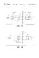
- FIG. 1Aillustrates a typical cochlear stimulation system as currently used by many patients, including an implantable cochlear stimulator (ICS) that is inductively coupled with an external headpiece (HP) connected with an external speech processor (SP) and power source;
- ICSimplantable cochlear stimulator
- HPheadpiece
- SPspeech processor
- FIG. 1Billustrates a behind-the-ear (BTE) cochlear stimulation system that includes an implanted cochlear stimulator (ICS) and an external BTE unit that includes a power source, a speech processor and a microphone;
- BTEbehind-the-ear
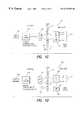
- FIG. 1Cshows one type of a single unit, fully implantable cochlear stimulation system
- FIG. 1Dshows one type of a fully implantable, partitioned, wired system in accordance with the invention.
- FIG. 1Eshows one type of a fully implantable, partitioned, proximity system in accordance with the invention.
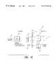
- FIGS. 2A, 2 B and 2 Cillustrate, respectively, three different configurations that may be realized using modularized fully implantable cochlear implant system (FICIS) in accordance with the present invention
- FIG. 2Dis a schematic block diagram of a preferred FICIS in accordance with the invention.
- FIG. 3Adepicts a top view of an FICIS made in accordance with the invention, and further illustrate the manner in which the pigtail lead originating at the ICS module is detachably connected to the connector of the ISP module, and wraps around the ISP module in the edge channel groove of the ISP module;
- FIG. 3Bdepicts a side view of the FICIS shown in FIG. 3A, with the pigtail lead being wrapped around the ISP module;
- FIG. 3Cdiagrammatically illustrates the incisions which must be made to initially implant the FICIS and to subsequently explant the ISP module and replace it with a new one;
- FIGS. 4A and 4Bshow a side and top view, respectively, of an implanted cochlear stimulator (ICS) module made in accordance with the invention
- FIG. 4Cillustrates an enlarged side view of the ICS module of FIGS. 4A and 4B, with a portion of the modules walls cut away to show the construction and arrangement of internal components used within the ICS module;
- FIG. 5Ashows a top view of an ISP module made in accordance with the invention, with a pigtail lead attached thereto;
- FIG. 5Billustrates a side view of the ISP module of FIG. 5A, and further depicts one type of internal microphone that may be used therein, as well as the edge channel groove for holding the wrapped pigtail lead;
- FIGS. 6A and 6Bshow a side and top view, respectively, of an implanted cochlear stimulator (ICS) as in FIGS. 4A-4C, and further show one way, using a deep indentation in the shell, that electrical connection may be made with the non-hermetically sealed RF coil on the outside of the ICS shell from an hermetically-sealed location on the inside of the ICS shell;
- ICSimplanted cochlear stimulator
- FIG. 6Cillustrates an enlarged side view of the ICS module of FIGS. 6A and 6B, with a portion of the module's walls cut away to show the construction and arrangement of internal components used within the ICS module;
- FIGS. 7A and 7Bshow a side and top view, respectively, of an implanted cochlear stimulator (ICS) as in FIGS. 4A-4C, and further show another way, using a shallow indentation in the shell in conjunction with a titanium tube, that electrical connection may be made with the non-hermetically sealed RF coil on the outside of the ICS shell from an hermetically-sealed location on the inside of the ICS shell; and
- ICSimplanted cochlear stimulator
- FIG. 7Cillustrates an enlarged side view of the ICS module of FIGS. 7A and 7B, with a portion of the module's walls cut away to show the construction and arrangement of internal components used within the ICS module.
- the present inventionrelates generally to a fully implantable system having a rechargeable battery (or other power source). Such systems are described, including the rechargeable battery portion, in Applicant Faltys' copending patent application Ser. No. 09/126,615, filed Jul. 31, 1998, now U.S. Pat. No. 6,067,474, which patent is incorporated herein by reference.
- a preferred embodiment of the present inventionrelates to an implantable cochlear stimulation system that is partitioned into two components: (1) a cochlear stimulator component and associated electrode array which are designed to last for the life of the patient; and (2) an implantable speech processor and battery component which are designed to be explanted and replaced from time to time. It is to be understood, however, that other embodiments of the invention may be used, For example, the invention may be practiced in a single implantable component which comprises a fully implantable cochlear stimulation system. It is also to be understood that the present invention need not be limited to just a cochlear stimulation system.
- Any medical or other device or system which must be implanted in living tissue, or a similar environment, and which requires operating power from a replenishable power source, such as a rechargeable battery, and wherein the operating power must be inductively or magnetically or otherwise coupled into the implantable device without a direct electrical connection,may benefit from the application and teachings of the present invention.
- cochlear stimulation systemswhich are generally representative of all tissue-stimulating systems.
- a representative cochlear stimulation system of the type currently used by many patientsis fully described, e.g., in U.S. Pat. No. 5,776,172, previously referenced and incorporated herein by reference.
- the external componentsinclude a speech processor (SP), a power source (e.g., a replaceable battery), and a headpiece (HP) 106 .
- SP and power sourceare typically housed within a wearable unit 102 that is worn or carried by the patient.
- the wearable unitis electrically connected to the HP 106 via a cable 104 .
- a microphone 107is also included as part of the headpiece 106 .
- the implanted componentsinclude an implantable cochlear stimulator (ICS) 112 and an array of electrodes 114 .
- the electrode array 114is intended for implantation within the cochlear of the patient.
- the ICS 112is implanted behind the ear, so as to reside near the scalp.
- the electrode array 114is permanently connected to the ICS by way of a multi-conductor implantable cable 116 .
- a coilthat is used to inductively or magnetically couple a modulated ac carrier signal to a similar coil that is included within the ICS 112 .
- a magnetis typically included within both the headpiece 106 and the ICS 112 , and the resulting magnetic attraction between the two magnets not only aligns the coils, as desired, but also provides a holding force that maintains the headpiece 106 securely against the scalp or skin 110 of the patient.
- the use of such a magnetmay, for some patients, limit their ability to have magnetic resonance imaging (MRI) performed on them, at least in the vicinity of the head.
- MRImagnetic resonance imaging
- a carrier signalis generated by circuitry within the wearable unit 102 using energy derived from the power source within the speech processor unit 102 .
- Such carrier signalwhich is an ac signal, is conveyed over the cable to the headpiece 106 where it is inductively coupled to the coil within the ICS 112 . There it is rectified and filtered and provides a dc power source for operation of the circuitry within the ICS 112 .
- Soundsare sensed through the external microphone 107 , amplified and processed by circuitry included within the speech processor unit 102 , and converted to appropriate stimulation signals in accordance with a selected speech processing strategy by circuitry within the speech processor unit 102 .
- These stimulation signalsmodulate the carrier signal that transfers power to the ICS 112 .
- the ICSincludes an appropriate demodulation circuit that recovers the stimulation signals from the modulated carrier and applies them to the electrodes within the electrode array 114 .
- the stimulation signalsidentify which electrodes, or electrode pairs, are to be stimulated, the sequence of stimulation and the intensity of the stimulation.
- Some embodiments of the ICS 112include a back telemetry feature that allows data signals to be transmitted from the ICS 112 to the headpiece 106 , and hence to the Speech Processor 102 .
- Such back telemetry dataprovides important feedback information to the speech processor regarding the operation of the ICS, including the amount of power needed by the ICS. See, e.g., copending patent application Ser. No. 08/932,565, filed Sep. 19, 1997, now U.S. Pat No. 5,876,425, issued to the same assignee as the present application, and also incorporated herein by reference.
- an external programming unit 108is detachably connected to the SP unit 102 .
- a clinicianor other medical personnel, is able to select the best speech processing strategy for the patient, as well as set other variables associated with the stimulation process. See, e.g., U.S. Pat. No. 5,626,629, incorporated herein by reference, for a more detailed description of a representative fitting/diagnostic process.
- the wearable unit 102must be worn or carried by the patient, and the cable 104 , which may be up to one meter long, must be routed from the unit 102 to the headpiece 106 .
- Some patientsfind wearing the unit 102 to be inconvenient, and find the use of the headpiece 106 , with its cable 104 , to be unsightly and uncomfortable.
- a behind-the-ear (BTE) unit 120has been proposed, as illustrated in FIG. 1 B.
- the BTE unit 120may include everything that was previously included within the wearable unit 102 , only in a much smaller volume.
- the BTE unit 120thus includes a suitable power source, as well as the circuitry needed for performing a desired speech processing function. With the BTE unit 120 , there is thus no need for the cable 104 , and the patient simply wears the BTE unit behind his or her ear, where it is hardly noticed, especially if the patient has hair to cover the BTE unit.
- the batteries employed within the wearable unit 102 (FIG. 1A) or the BTE unit 120 (FIG. 1B)may be readily replaced when needed. Still, the BTE unit 120 may become uncomfortable to wear when worn for long periods of time, and must be removed at certain times, such as when swimming or bathing. Some patients would thus like the convenience of being able to hear at all times, including when swimming or bathing, and thus a fully implantable stimulation system is desired.
- the present inventionis directed to fully implantable devices and systems that employ a rechargeable battery or other replenishable power source. While it is known in the art to use an implantable stimulating device with a rechargeable battery, see, e.g, U.S. Pat. No. 3,942,535, such recharging systems require a bulky external recharging system, and are time consuming to use.
- the present inventionwhich uses a rechargeable battery, allows the recharge operation to occur quickly and conveniently, without significant impact on the patient's lifestyle.
- the present inventionalso allows different implant configurations to be used as part of the fully implantable system, including, in one embodiment, the ability to use the ICS 112 of the prior systems in a fully implantable system.
- FIG. 1 CA fully implantable single component system 130 made in accordance with the invention is shown in FIG. 1 C.
- such system 130includes the ICS circuitry, the speech processor circuitry, and a power source within a single unit 132 .
- An electrode array 114is connected to the single unit 132 in conventional manner.
- a microphone 134is coupled via a telecoil link to the single unit 132 .
- Such telecoil linkpowers the microphone circuits through magnetic coupling from the unit 132 .
- Sounds sensed by the microphone 134are transmitted to the unit 132 via an rf transmitter built-in to the microphone 134 .
- the transmission distance for such signalis very short, only a centimeter or two, so not much power is needed for such transmission.
- such microphone 134may be inserted inside the ear canal so it is not visible externally.
- microphonesmay also be used with the implant unit 132 .
- externally-generated sound wavesmay be sensed through the patient's skin and case shell or wall of the single unit 132 at locations where the case shell or wall is properly supported and of the proper thickness.
- an external headpiece 136When the battery included within the single unit 132 needs to be recharged, which may only be a few minutes a day, or a few times during the week, an external headpiece 136 is placed adjacent the unit 132 , and inductive coupling is used to transfer charging power to the unit's battery.
- the external headpiececonnects to an external control unit 138 , which may, in turn, derive its power from replaceable batteries or from an ac power plug.
- an external programmer 108may be detachably connected to the external control unit 138 .
- the external control unit 138may thus be used to charge/recharge the battery within the implanted unit 132 , as well as for other purposes.
- the external control unit 138may be used to override the internal speech processor with an external speech processor, e.g., a speech processor included within the external programmer 108 .
- the external control unit 138may be used to boost the power provided by the internal battery.
- the external control unit 138may also be used for programming the implant device 132 , e.g., fitting the ICS after implant or adjusting the stimulation parameters of the fully implantable unit 132 , as well as for diagnostic purposes.
- back telemetrymay be employed to allow data signals to be sent from the implanted unit to the external headpiece 136 , and hence to the external control unit 138 .
- a “wired system” embodiment 150 of the inventionis depicted.
- at least two separate implantable units 152 and 154are employed and the circuits of the system are partitioned between the two units.
- a first unit 152for example, speech processor (SP) and ICS circuitry are housed, and such unit is permanently connected to an electrode array 114 .
- a second unit 154a battery, or other suitable power source, is housed.
- the second unit 154is electrically connected to the first unit 152 via a detachable cable 156 .
- Other embodiments of the partitioned systemmay, as explained below, place the ICS circuitry in one unit, and the SP and battery in the other unit.
- ac powershould be coupled from the power unit 154 to the other unit 152 , thereby preventing any possibility that a dc current might flow through the tissue through which the cable is routed. This is important because a dc current could cause damage to the tissue, whereas an ac current will not. Also, because the cable is not hermetically insulated from the surrounding tissue, it is very possible that minor leakage current could flow through the tissue if it carried dc currents.
- the unit 154includes appropriate switching circuitry that converts the dc power associated with the battery (or other power storage element) therein to an ac signal for coupling to the first unit 152 . Also, appropriate circuitry is employed to allow ac power induced into the unit 152 from the external headpiece 136 to be directed to the battery in the unit 154 in order to charge the battery.
- an ultracapacitoralso known as a supercapacitor
- An ultracapacitorlike a conventional capacitor, allows an electric charge (voltage potential) to be stored therein.
- the energy density of the ultracapacitoris orders of magnitude greater than the energy density of a normal capacitor, thereby allowing a great amount of energy to be stored in the ultracapacitor. This stored energy may then be withdrawn from the ultracapacitor for subsequent use.
- the ultracapacitorprovides a viable alternative to a rechargeable battery for use within the implantable system.
- a complete-in-canal (CIC) microphone 134 of the type described previouslymay be used to sense sounds and couple signals representative of such sounds to the speech processor (SP) circuits within its respective implantable portion.
- SPspeech processor
- FIG. 1Dwhich shows that the ICS and SP circuitry are included within the first implantable unit 152 , and which shows that the power source, e.g., rechargeable battery, is included within the second implantable unit 154 , is only exemplary.
- the SP circuitryis included within the second implantable unit 154 , leaving only the ICS circuitry within the first implantable unit 152 .
- the advantage of the wired system 150 shown in FIG. 1Dis that a fully implantable system is provided wherein one of the two implantable units, e.g., the power unit 154 , may be replaced, if necessary, through only minor surgery.
- the cable 156 that connects the second unit 154 to the first unit 152is detachable.
- the implantable connector that connects the cable 156 to the unit 154may be of any suitable type, e.g., of the type commonly used with implantable pacemakers, or of the pressure type shown in U.S. Pat. No. 4,516,820 (Kuzma), incorporated. herein by reference, or of the type shown in U.S. Pat. No. 4,495,917 (Byers), also incorporated herein by reference.
- the external headpiece 136 and external control unit 138 , and programmer 108may be used with the wired system embodiment 150 shown in FIG. 1D in the same manner as these components are used with the single unit embodiment 130 shown in FIG. 1 C.
- a partitioned proximity system 160is shown that is similar to the wired system 150 shown in FIG. 1D, but without the use of a connecting cable 156 connected between the two units.
- a first implantable unit 112 ′comprises an ICS with an electrode array 114 connected thereto.
- An advantage of the proximity system 160is that the first implantable unit 112 ′ may be substantially the same as, or identical to, that of the ICS 112 used in existing cochlear stimulation systems (see FIG. 1A or FIG. 1 B). This allows existing stimulation systems having an ICS 112 to be upgraded to a fully implantable system as shown in FIG. 1E.
- a second implantable unit 162includes speech processor (SP) circuits and a power source, e.g., a rechargeable battery.
- SPspeech processor
- the second unit 162is implanted so as to be in close proximity to the first unit 112 ′.
- a preferred configurationincludes a two-conductor cable or lead having one end detachably connected to the unit 162 and having a coil attached at its other end and placed or positioned against or near the first unit 112 ′ so as to be aligned with the coil included within the first unit 112 ′.
- An edge channel groveis formed around the periphery of the second unit 162 , and provides a convenient channel into which the cable or lead may be wound, like the string of a yo-yo, as the second unit 162 is positioned adjacent the first unit 112 ′. This allows inductive coupling to occur between the implantable units 112 ′ and 162 in the same manner as occurs between the BTE unit 120 and the ICS 112 shown in FIG. 1B, or between the headpiece 106 and the ICS 112 shown in FIG. 1 A.
- a suitable microphonee.g., an complete-in-canal (CIC) microphone 134 of the type described previously, may be used to sense sounds (pressure waves) and couple electrical signals representative of such sounds to the speech processor (SP) circuits within the implantable portion 162 .
- a suitable microphonemay be fashioned as an integral part of the second unit 162 .
- the external headpiece 136 and external control unit 138 , and programmer 108may be used with the partitioned proximity system embodiment 160 shown in FIG. 1E in the same manner as used with the single unit embodiment 130 shown in FIG. 1 C and the partitioned wired system embodiment 150 shown in FIG. 1 D.
- implantable systems 112may be upgraded to fully implantable systems without replacing the implant unit 112 and electrode 114 ;
- implantable systemsmay be upgraded with improved battery (or other power source) technology and lower-power more-sophisticated SP circuits, as such become available, with only minor surgery for the patient;
- batteriescan be replaced with only minor surgery, as required;
- charging, override, power boost, fitting and diagnosticsmay be performed by simply overriding the implanted SP circuits with an external speech processor.
- FIGS. 2A, 2 B and 2 CThree possible configurations of such a preferred FICIS are respectively illustrated in FIGS. 2A, 2 B and 2 C; and a functional block diagram of such a preferred FICIS is illustrated in FIG. 2 D.
- the FICIScomprises a modularized system that includes various combinations of at least three modules.
- the three modulesinclude: (1) a small implantable cochlear stimulator (ICS) module 10 , with permanently attached cochlear electrode array 12 ; (2) an implanted speech processor (ISP) module 30 , with integrated microphone 32 and rechargeable battery 34 ; and (3) an external module 50 .
- the external module 50comprises an external speech processor (ESP) module.
- the external module 50comprises an external battery charger (EBC) module.
- the present inventionis not directed, per se, to the specific electronic circuitry or electronic componentry used or housed within each of these four modules. Any type of suitable circuitry could be used in the modules that performs the functions indicated. Circuitry and componentry suitable for these purposes is disclosed, e.g., in the referenced patents. The present invention, rather, is directed to a system that combines the indicated modules in a way that provides the advantages and benefits enumerated herein, which advantages and benefits have not heretofore been available.
- the ICS module 10includes ICS circuitry 14 hermetically sealed in compartment 15 .
- Electrical feed-through pins (“feedthrus”) 17 and 19connect a coil 20 to the ICS circuitry 14 .
- the coil 20is thus not housed within the hermetically sealed compartment 15 , but is embedded within a suitable biocompatible substance 21 , e.g., epoxy molding, which is affixed to the walls of the sealed compartment 15 .
- Other feedthrus 22electrically connect the electrode array 12 to the ICS circuitry 14 through an non-hermetic compartment 23 , as explained more fully below in conjunction with FIG. 4 C.
- the electrode array 12includes a multiplicity of spaced-apart electrode contacts 13 at its distal end, which electrode contacts are adapted to be placed inside of the cochlear in order to provide an electrical stimulus to the tissue within the cochlear.
- a typical electrode array 12may include, e.g., anywhere from 8 to 22 electrode contacts 13 .
- one embodiment of the present inventionutilizes a two-conductor lead 18 that is electrically connected in parallel with the coil 20 . That is, one of the conductors of the lead 18 , which may hereafter be referred to as a “pigtail” lead, is electrically connected to the feedthru 17 , and the other of the conductors of the lead 18 is electrically connected to the feedthru 19 .
- a jack 25including, e.g., a tip electrode 24 (connected through one of the conductors of the lead 18 to the feedthru 17 ) and a ring electrode 26 (connected through the other of the conductors of the lead 18 to the feedthru 19 ), or other suitable electrode contacts, are located at a distal end of the lead 18 .
- the ISP module 30includes an hermetically sealed compartment 31 wherein ISP and other electronic circuitry 33 (hereafter “ISP circuitry” 33 ) is housed, along with a piezo-microphone 32 and a rechargeable battery 34 .
- Feedthrus 35 and 37electrically connect the ISP circuitry 33 to an electrical connector 36 formed in a suitable biocompatible material, e.g., epoxy molding, affixed to one side or edge of the ISP module 30 .
- the jack 25 at the distal end of the lead 18may be detachably inserted into the connector 36 .
- the tip electrode 24makes electrical contact through feedthru 35 with the ISP circuitry 33
- the ring electrode 26makes electrical contact through feedthru 37 with the ISP circuitry 33 .
- this type of connectoris similar to the basic connectors used in the pacemaker art in order to detachably connect a pacing lead to an implanted pacemaker. See, e.g., U.S. Pat. No. 4,764,132 (Stutz, Jr.) and the art cited therein.
- One embodiment of the present inventionincludes the use of an RF lead 18 ′ in place of the pigtail lead 18 .
- the RF lead 18 ′has a jack 25 ′ at one end having a tip electrode 24 ′ and a ring electrode 26 ′, adapted for insertion into the connector 36 of the ISP module 30 .
- an RF coil 20 ′At the other end of the lead 18 ′ is an RF coil 20 ′.
- the coil 20 ′ of the RF lead 18 ′is positioned as close as possible to, and in alignment with, the coil 20 embedded within the molded epoxy 21 of the ICS module 10 .
- both the ICS module 10 and the ISP module 30are adapted to be implanted beneath the skin layer 110 of the patient.
- the battery 34has sufficient charge stored therein, the operation of the ICS module 10 and ISP module 30 proceeds without assistance from any external components.
- the system created by the ICS module 10 and ISP module 30is self-sufficient, and truly becomes a fully implantable cochlear implant system that provides the patient with the sensation of hearing.
- the fully implantable systemmay be assisted or boosted with an external module 50 .
- external module 50may be needed, e.g., to charge the battery 34 , or to override the ISP circuitry 33 with external speech processing controls and commands.
- external module 50includes a headpiece 50 ′, having a coil 52 therein.
- the headpiece 50 ′may also include an external microphone.
- the headpiece 50 ′is connected to an external unit 54 , which external unit comprises appropriate electronic circuitry, e.g, an external speech process (ESP) or an external battery charger (EBC).
- ESPexternal speech process
- EBCexternal battery charger
- the external unit 54is powered from an external power source 56 .
- the external power sourcewill comprise a replaceable battery.
- the external power sourcecould conceivably be any available power source, including batteries, including either replaceable or rechargeable batteries; charged super capacitors; dc power supplies connected to the ac line voltage (110 vac, 60 Hz); solar panels; hand-operated generators; or the like.
- batteriesincluding either replaceable or rechargeable batteries; charged super capacitors; dc power supplies connected to the ac line voltage (110 vac, 60 Hz); solar panels; hand-operated generators; or the like.
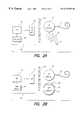
- FIG. 2Aillustrates one variation of the invention that is particularly well suited for young children.
- This variationincludes an ICS module 10 used with an ESP module 60 .
- the ESP module 60includes a headpiece and microphone 50 ′, an external speech processor 62 and related circuitry, powered by a battery 56 ′.
- the variation shown in FIG. 2Ais similar to existing cochlear stimulation systems (see, e.g., FIG. 1 A).
- the configuration shown in FIG. 2Ais especially suited for small children where the head size and bone thickness cannot accommodate the entire FICIS system.
- the primary goal of this configurationis to upgrade it to a fully implantable system once the patient has grown sufficiently so that the head size and bone thickness are no longer a limitation.
- the advantage of the variation shown in FIG. 2Ais that in can readily be upgraded to a fully implantable system at a later date by adding an ISP module 30 .
- the ISP module 30may be added using either of two approaches.
- a first approachan ICS module 10 with pigtail lead 18 is first implanted, with the pigtail lead 18 not being used, as shown in FIG. 2 A. That is, the jack 25 at the distill end of the pigtail lead 18 is not connected to anything when the ICS module 10 is first implanted.
- the jack 25will be protected with a suitable insulating protective cover or sleeve.
- Such unused pigtail lead 18may, in some instances, be wrapped around a “dummy” ISP module, which dummy ISP module would preserve a space within the pocket formed under the skin for the later-implanted real ISP module 30 . In small children, however, such “dummy” module would likely not be used, but rather the pigtail lead 18 , with protective sleeve, would simply be coiled under the skin in the region where the later-implanted ISP module would eventually be located.
- the pigtail lead 18may be extracted through an incision, connected to a new ISP module 30 , and the ISP module 30 could then be implanted, coiling the pigtail lead 18 around it, as described below.
- the ICS module 10is implanted first. Then, at a later date, when the ISP module 30 is to be implanted, an incision is made next to the ICS module 10 and a pocket is formed under the skin. An RF lead 18 ′ is connected to the ISP module 30 by way of the connector 36 . The coil 26 at the other end of the RF lead 18 ′ is pushed into the pocket and positioned adjacent to and aligned with the embedded RF coil 20 of the ICS module 10 . The ISP module 30 is then inserted into the pocket with a rotation movement so as to wind the lead 18 ′ around the edge of the module as it is inserted. An edge channel grove is provided around the periphery of the ISP module 30 to facilitate this process. The incision that opens into the pocket is then closed with appropriate suturing or other means.
- a second configuration of the inventionuses an ICS module 10 with an ISP module 30 .
- Periodic recharging of the battery 34 within the ISP moduleis performed using an external module 64 that includes a headpiece 51 , an external battery charger (EBC) 58 , and an external power source 56 .
- EBCexternal battery charger
- the configuration shown in FIG. 2Brepresents a fully implantable system that is self-sufficient for as long as the battery 34 in the ISP module remains charged. Typically, such battery 34 should last, under normal use, for at least two days.
- the battery 34requires periodic recharging, which recharging may preferably occur overnight during sleep using the EBC 58 and related components.
- a third configuration of the inventionuses an ICS module 10 with an ISP module 30 with assistance from an external speech processor (ESP) module 60 .
- the ESP module 60is essentially the same as that described above in connection with FIG. 2 A. Such module 60 is used to drive (control) the ICS module 10 and at the same time apply a slow charge to the implanted battery 34 contained within the ISP module 30 .
- the ESP module 60may be used jointly with the internal speech processor 33 contained within the ISP module 30 , or alternatively to take over the function of the internal speech processor should it malfunction or otherwise require replacement.
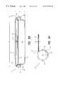
- FIGS. 3A and 3Ba top and side view, respectively, of an FICIS made in accordance with the invention is shown.
- These figuresillustrate how the pigtail lead 18 , originating at the ICS module 10 , may be detachably connected to the connector 36 of the ISP module when the lead 18 is fully extended.
- the ISP module 30is rotated (e.g., clockwise as shown in FIG. 3 A), causing the lead 18 to wrap around an edge channel groove 39 of the ISP module.
- This rotationcauses the ISP module to pull up close to the ICS module 10 , much like a yo-yo climbing a string. Having the ISP module adjacent the ICS module 10 is the desired position for the two modules when implanted.
- the ISP module 30When replacement of the ISP module 30 is required, e.g., to replace the battery 34 (which would typically not be needed for several years), then all the surgeon need do is make a relatively small incision 72 , having a length approximately equal to the diameter of the ISP module. Once the relatively short incision 72 has been made, the ISP module 30 is grabbed, e.g., with the surgeon's fingers of a forceps tool, and carefully removed from the pocket, rotating it in the appropriate direction as it is removed. As it is removed, the lead 18 thus unwinds until, when fully removed from the pocket, the lead 18 is straight and can be easily detached from the connector 36 .
- the jack 25 at the end of the lead 18is cleaned, as required, and inserted into the connector 36 if a new ISP module 30 .
- the new ISP module 30is then inserted back into the pocket, through the incision 72 , rotating it as it is so inserted, so that the lead 18 once again wraps around the edge channel grove 39 of the ISP module 30 .
- the incision 72is closed in conventional manner.
- the above replacement processadvantageously allows an old ISP module 30 to be explanted, the lead 18 to be disconnected from the old ISP module, the lead 18 connected to a new ISP module, and the new ISP module with lead 18 attached to be implanted, all using a relatively simple surgery, without disturbing the implanted ICS module, and its cochlear electrode array. Such surgery can, in most instances, be performed on an outpatient basis, without the necessity and expense of using a hospital operating room.
- FIGS. 4A and 4Ba side and top view, respectively, of an implanted cochlear stimulator (ICS) module 10 made in accordance with a preferred embodiment of the invention is illustrated.
- the cochlear electrode lead 12 and the pigtail lead 18have been omitted.
- the module 10is preferably circular in shape, having an outer diameter D 1 , where D 1 is about 25 mm, and an inner (cavity) diameter D 2 , whre D 2 is about 20 mm.
- the thickness T of the module 10is about 5 mm.
- the ICS module 10has the general appearance of a large button.
- FIG. 4Cillustrates an enlarged side view of the ICS module of FIGS. 4A and 4B, with a portion of the walls of the module cut away to show the preferred construction and arrangement of the internal components used therewithin.
- the preferred constructionis a clam-shell construction, wherein a top shell 82 , having an outwardly protruding flange 82 ′ around its periphery, and a bottom shell 83 , also having an outwardly protruding flange 83 ′, are bonded together at the flanges by welding the flanges together.
- An inner shell 84having a smaller diameter than the lower shell 83 , and also having an outwardly protruding flange 84 ′, fits inside of the lower shell 84 .
- the flange 84 ′is bonded to the flanges 82 ′ and 83 ′ by being sandwiched between the flanges 82 ′ and 83 ′ as the weld is made. In this manner, all three flanges 82 ′, 83 ′ and 84 ′ are welded together. All three shells 82 , 83 and 84 are preferably made from titanium alloy 6AL/4D.
- the space inside of the shells 84 and 82represents an hermetically sealed cavity 15 wherein electronic circuitry, e.g., an integrated circuit 86 , may be mounted on a printed circuit board (PCB) 85 .
- PCBprinted circuit board
- Feedthrus 20 , as well as feedthrus 17 and 19 (see FIG. 2D)are spaced around the periphery of the PCB 85 and pass through the flange 84 ′ of the inner shell 84 to the space 23 inside the lower shell 83 and outside the inner shell 84 .
- Such space 23thus represents a non-hermetically sealed compartment that encircles the module 10 just inside of the lower shell 83 around its periphery.
- non-hermetic compartment 23facilitates electrical connection of the non-hermetically sealed portion of the feedthrus with the appropriate lead or coil. Once all the electrical connections have been made inside of the non-hermetic compartment 23 , such compartment may be injected with a suitable dielectric filler material, e.g., a biocompatible epoxy or silicone.
- a suitable dielectric filler materiale.g., a biocompatible epoxy or silicone.
- the coil 20 used by the ICS module 10is preferably embedded within a suitable biocompatible epoxy molding material 21 positioned on top of the flange 82 ′.
- the ends of the wire from which the coil 20 is mademust be electrically connected with electrical circuitry located inside of the hermetically-sealed compartment.
- electrical circuitrylocated inside of the hermetically-sealed compartment.
- the ends of the wires from the coil 20may pass through the welded flange 82 ′/ 83 ′/ 84 ′, e.g., through one or more holes, and similarly pass through one or more holes in the shell 83 into the non-hermetic compartment 23 , where they may be connected to the feedthrus 17 and 19 .
- one way to connect the ends of the wires from the coil 20 with electronic circuitry inside of the hermetically-sealed portions of the ICS module 10is to use a deep indentation 102 in the upper shell 82 , as illustrated in FIGS. 6A, 6 B and 6 C.
- Such deep indentation 102provides an opening or channel to a lower surface 104 through which a hole 105 or 106 can be made into the non 10 hermetically sealed cavity 23 .
- one end 108 of the wire from the coil 20passes through opening 106 into the non-hermetically sealed cavity 23 , where it is attached to feedthru 19 .
- the shells 82 and 84must remain hermetically sealed to each other.
- the other end of the wire from coil 20may pass through another opening 105 at the bottom 104 of the indent 102 into the non-hermetically sealed cavity 23 , where it may be attached to feedthru 17 (see FIG. 2 D).
- Another way to connect the ends of the wires from the coil 20 with the electronic circuitry inside of the hermetically-sealed portions of the ICS module 10is to use a shallow indentation 110 in the upper shell 82 and a titanium (or titantium alloy) tube 112 as depicted in FIGS. 7A, 7 B and 7 C.
- the tube 112is hermetically sealed with shells 82 and 84 on both ends.
- the wire end 108may thus be fed through an upper end 114 of the tube 112 and passed into the non-hermetical compartment 23 , where it can be attached to the feedthru 19 .
- another tube, having an upper end 116may be hermetically sealed with shells 82 and 84 so that the other end of the wire from which coil 20 is made may pass through it into the non-hermetically sealed cavity 23 .
- the two wire ends from the coil 20may pass through the same opening or tube into the non-hermetically sealed cavity.
- the manufacture and connection of a large number of conductorsis greatly facilitated.
- the cochlear electrode array 12may pass directly through an opening in the outer shell 83 into the non-hermetic cavity 23 , where each of the conductor wires used in such electrode array may connect with respective feedthrus 22 (see FIG. 2 D).
- a centrally located cavity or detentis formed within the upper shell 82 .
- Such detentprovides a cavity wherein a permanent magnet 87 may be removably inserted.
- a permanent magnet 87may be removably inserted.
- such magnet 87facilitates proper alignment of the coil 20 with an external coil within a headpiece, when an external unit 50 is used.
- such magnet 87may interfere with needed medical resonance imaging (MRI), should such imaging be necessary in the vicinity of the skull.
- MRImedical resonance imaging
- the patientmay thus elect not to use a magnet at the outset of the cochlear implant surgery; or, in the event MRI is subsequently indicated for the patient, the magnet may be surgically removed by making a small incision above the ICS module and pulling the magnet out, while leaving the ICS module 10 intact so that it can perform its intended function.
- FIGS. 5A and 5Bshow a top and side view, respectively, of a preferred ISP module 30 .
- the ISP module 30is preferably made from titanium alloy 6AL/4D, a well-proven material for use in implantable devices.
- the module 30is generally circular in shape, typically having an approximate diameter D 3 , where D 3 is about 32 mm, and a thickness, or height H, where H is about 6 mm.
- the pigtail lead 18which is a two-conductor lead, has a diameter D 4 , where D 4 is about 2 mm.
- the shell 90comprises a lower shell and has side walls approximately equal to the height of the module.
- the shell 91functions as an inverted (concave) lid for the shell 90 .
- the shell 92functions as a lid (convex) for the shell 91 .
- Such arrangementthus creates a lower battery compartment 95 that represents about 3 ⁇ 4 of the available volume within the module, and an upper electronic compartment that represents about 1 ⁇ 4 of the available volume.
- Each shellincludes peripheral flanges that contact each other around an upper periphery rim 97 .
- This rim 97provides a convenient location where a weld can be made to hermetically seal the entire unit, including both compartments.
- the connector 36into which the jack 25 of the pigtail lead is detachably inserted, is formed along one segment of the perimeter of the module 30 .
- Such connectoris formed, e.g., using the same techniques and materials as have been used for years in making pacemaker connectors.
- an L-shaped flange bracket 98is welded around the perimeter of the module 30 .
- the flange bracket 98in combination with the periphery rim 97 , create the edge channel groove 39 into which the pigtail coil 18 is wound when the ISP module 30 is implanted next to the ICS module 10 , as explained previously.
- a microphoneis created using the upper shell 92 , in combination with a coupling junction element 93 and a piezo-crystal microphone 94 .
- Sound (pressure) vibrationspass through the skin 110 of patient and impinge on the upper shell 92 .
- Such pressure wavesare then coupled through the coupling junction 93 to the piezo-crystal microphone 94 .
- the piezo-crystal microphone 94responds to such pressure waves by generating an electrical signal that varies as a function of the sensed pressure waves, as is known in the art.
- a CIC microphonemay be used to provide another source of audio signals for processing by the implantable speech processor.
- the battery 34typically has a rectangular form factor that fits within the battery compartment 95 .
- Empty regions 99 created by the mismatch between the rectangular form factor of the battery 34 and the round shape of the module 30may be used, as needed, to house some of the larger electronic components, e.g., capacitors, used with the ISP circuitry.
- the present inventionprovides a modular-based fully implantable cochlear implant system (FICIS).
- FICISfully implantable cochlear implant system
- Such systemadvantageously is flexible in its application so as to meet the particular needs and wants of a given patient at a given time, including the ability to adapt to a range of head sizes and shapes.
- the inventionprovides such a modular-based FICIS that offers a relatively simple and low-risk replacement surgery for its battery module, e.g., the ISP module.
- the inventionprovides such a modular-based FICIS that is highly reliable, exhibiting, e.g., life-time reliability for the ICS module, cochlear electrode array, and pigtail lead (when used), and further exhibiting a reliability of the ISP module that is equal to or better than the maximum life of the battery used therein.
Landscapes
- Health & Medical Sciences (AREA)
- Engineering & Computer Science (AREA)
- Biomedical Technology (AREA)
- Nuclear Medicine, Radiotherapy & Molecular Imaging (AREA)
- Radiology & Medical Imaging (AREA)
- Life Sciences & Earth Sciences (AREA)
- Animal Behavior & Ethology (AREA)
- General Health & Medical Sciences (AREA)
- Public Health (AREA)
- Veterinary Medicine (AREA)
- Otolaryngology (AREA)
- Prostheses (AREA)
Abstract
Description
Claims (13)
Priority Applications (1)
| Application Number | Priority Date | Filing Date | Title |
|---|---|---|---|
| US09/407,826US6272382B1 (en) | 1998-07-31 | 1999-09-28 | Fully implantable cochlear implant system |
Applications Claiming Priority (3)
| Application Number | Priority Date | Filing Date | Title |
|---|---|---|---|
| US09/126,615US6067474A (en) | 1997-08-01 | 1998-07-31 | Implantable device with improved battery recharging and powering configuration |
| US10892398P | 1998-11-17 | 1998-11-17 | |
| US09/407,826US6272382B1 (en) | 1998-07-31 | 1999-09-28 | Fully implantable cochlear implant system |
Related Parent Applications (1)
| Application Number | Title | Priority Date | Filing Date |
|---|---|---|---|
| US09/126,615Continuation-In-PartUS6067474A (en) | 1997-08-01 | 1998-07-31 | Implantable device with improved battery recharging and powering configuration |
Publications (1)
| Publication Number | Publication Date |
|---|---|
| US6272382B1true US6272382B1 (en) | 2001-08-07 |
Family
ID=26806423
Family Applications (1)
| Application Number | Title | Priority Date | Filing Date |
|---|---|---|---|
| US09/407,826Expired - LifetimeUS6272382B1 (en) | 1998-07-31 | 1999-09-28 | Fully implantable cochlear implant system |
Country Status (1)
| Country | Link |
|---|---|
| US (1) | US6272382B1 (en) |
Cited By (222)
| Publication number | Priority date | Publication date | Assignee | Title |
|---|---|---|---|---|
| US20020051550A1 (en)* | 2000-08-25 | 2002-05-02 | Hans Leysieffer | Implantable hermetically sealed housing for an implantable medical device and process for producing the same |
| US20020110715A1 (en)* | 1998-10-23 | 2002-08-15 | Schulman Joseph H. | Zinc air battery and its uses |
| US20030032874A1 (en)* | 2001-07-27 | 2003-02-13 | Dexcom, Inc. | Sensor head for use with implantable devices |
| US20030036782A1 (en)* | 2001-08-20 | 2003-02-20 | Hartley Lee F. | BioNet for bilateral cochlear implant systems |
| US6542777B1 (en)* | 2001-01-19 | 2003-04-01 | Advanced Bionics Corporation | Spiral shield for a flexible high-Q implantable inductively coupled device |
| US6572531B2 (en) | 2000-06-17 | 2003-06-03 | Alfred E. Mann Foundation For Scientific Reseach | Implantable middle ear implant |
| US20030114905A1 (en)* | 1999-10-01 | 2003-06-19 | Kuzma Janusz A. | Implantable microdevice with extended lead and remote electrode |
| US20030125602A1 (en)* | 2002-01-02 | 2003-07-03 | Sokolich W. Gary | Wideband low-noise implantable microphone assembly |
| US20030139782A1 (en)* | 2002-01-21 | 2003-07-24 | Michael Duncan | FES stimulator |
| US6611718B2 (en) | 2000-06-19 | 2003-08-26 | Yitzhak Zilberman | Hybrid middle ear/cochlea implant system |
| US20030171783A1 (en)* | 2002-03-08 | 2003-09-11 | Quallion Llc | Battery terminal sealing and supporting device and method |
| US20030171785A1 (en)* | 2002-02-11 | 2003-09-11 | Michael Duncan | Distributed functional electrical stimulation system |
| US20030171787A1 (en)* | 2000-06-30 | 2003-09-11 | David Money | Cochlear implant |
| US20030181956A1 (en)* | 2002-01-21 | 2003-09-25 | Michael Duncan | Multi-purpose FES system |
| US6648813B2 (en) | 2000-06-17 | 2003-11-18 | Alfred E. Mann Foundation For Scientific Research | Hearing aid system including speaker implanted in middle ear |
| US20030229381A1 (en)* | 2002-06-03 | 2003-12-11 | Erwin Hochmair | Implantable device with flexible interconnect to coil |
| US20040019369A1 (en)* | 2002-03-11 | 2004-01-29 | Michael Duncan | Wireless functional electrical stimulation system |
| US6702857B2 (en) | 2001-07-27 | 2004-03-09 | Dexcom, Inc. | Membrane for use with implantable devices |
| US20040073275A1 (en)* | 2002-10-11 | 2004-04-15 | Maltan Albert A. | Cochlear implant sound processor with permanently integrated replenishable power source |
| US20040106963A1 (en)* | 2001-11-07 | 2004-06-03 | Quallion Llc | Implantable medical power module |
| US6775389B2 (en) | 2001-08-10 | 2004-08-10 | Advanced Bionics Corporation | Ear auxiliary microphone for behind the ear hearing prosthetic |
| US20040176817A1 (en)* | 2002-12-09 | 2004-09-09 | Medtronic, Inc. | Modular implantable medical device |
| WO2004103463A1 (en)* | 2003-05-16 | 2004-12-02 | Medtronic, Inc. | Implantable medical device with a nonhermetic battery |
| US20050004619A1 (en)* | 2003-05-16 | 2005-01-06 | Wahlstrand Carl D. | Headset recharger for cranially implantable medical devices |
| US20050004637A1 (en)* | 2003-05-16 | 2005-01-06 | Ruchika Singhal | Explantation of implantable medical device |
| US6842647B1 (en) | 2000-10-20 | 2005-01-11 | Advanced Bionics Corporation | Implantable neural stimulator system including remote control unit for use therewith |
| US20050020873A1 (en)* | 2003-07-23 | 2005-01-27 | Epic Biosonics Inc. | Totally implantable hearing prosthesis |
| US20050033382A1 (en)* | 2003-08-04 | 2005-02-10 | Peter Single | Temperature regulated implant |
| US6862465B2 (en) | 1997-03-04 | 2005-03-01 | Dexcom, Inc. | Device and method for determining analyte levels |
| US20050075696A1 (en)* | 2003-10-02 | 2005-04-07 | Medtronic, Inc. | Inductively rechargeable external energy source, charger, system and method for a transcutaneous inductive charger for an implantable medical device |
| US20050075698A1 (en)* | 2003-10-02 | 2005-04-07 | Medtronic, Inc. | Ambulatory energy transfer system for an implantable medical device and method therefore |
| US20050102006A1 (en)* | 2003-09-25 | 2005-05-12 | Whitehurst Todd K. | Skull-mounted electrical stimulation system |
| US20050136385A1 (en)* | 2003-12-19 | 2005-06-23 | Brian Mann | Flexible lead for digital cardiac rhythm management |
| US20050159791A1 (en)* | 2002-03-08 | 2005-07-21 | Christopher Daly | Cochlear implant |
| US20050177205A1 (en)* | 2004-01-09 | 2005-08-11 | Bomjun Kwon | Stimulation mode for cochlear implant speech coding |
| DE102004017832B3 (en)* | 2004-04-13 | 2005-10-20 | Siemens Audiologische Technik | hearing Aid |
| US20050251225A1 (en)* | 2004-05-07 | 2005-11-10 | Faltys Michael A | Cochlear stimulation device |
| US20060030905A1 (en)* | 2004-06-03 | 2006-02-09 | Cochlear Limited | External coil assembly for a transcutaneous system |
| US20060036293A1 (en)* | 2004-08-16 | 2006-02-16 | Whitehurst Todd K | Methods for treating gastrointestinal disorders |
| US20060085051A1 (en)* | 2004-10-19 | 2006-04-20 | Fritsch Michael H | Electrical implants |
| US20060100672A1 (en)* | 2004-11-05 | 2006-05-11 | Litvak Leonid M | Method and system of matching information from cochlear implants in two ears |
| WO2006071210A1 (en)* | 2003-12-24 | 2006-07-06 | Cochlear Americas | Transformable speech processor module for a hearing prosthesis |
| US20060149340A1 (en)* | 2002-07-31 | 2006-07-06 | Karunasiri Rankiri T | Systems and methods for providing power to one or more implantable devices |
| US20060149324A1 (en)* | 2004-12-30 | 2006-07-06 | Brian Mann | Cardiac rhythm management with interchangeable components |
| US20060161217A1 (en)* | 2004-12-21 | 2006-07-20 | Jaax Kristen N | Methods and systems for treating obesity |
| US20060184204A1 (en)* | 2005-02-11 | 2006-08-17 | Advanced Bionics Corporation | Implantable microstimulator having a separate battery unit and methods of use thereof |
| US20060184212A1 (en)* | 2004-05-07 | 2006-08-17 | Faltys Michael A | Cochlear Stimulation Device |
| US20060183965A1 (en)* | 2005-02-16 | 2006-08-17 | Kasic James F Ii | Integrated implantable hearing device, microphone and power unit |
| US20060200205A1 (en)* | 2005-03-01 | 2006-09-07 | Haller Matthew I | Systems and methods for treating a patient with multiple stimulation therapies |
| US20060212087A1 (en)* | 2005-03-15 | 2006-09-21 | Haller Matthew I | Implantable stimulator |
| US20060235484A1 (en)* | 2005-03-14 | 2006-10-19 | Jaax Kristen N | Stimulation of a stimulation site within the neck or head |
| US20060247728A1 (en)* | 2004-12-21 | 2006-11-02 | Foster Allison M | Methods and systems for treating autism by decreasing neural activity within the brain |
| US20060259091A1 (en)* | 2005-05-16 | 2006-11-16 | Ries Andrew J | Method and apparatus for forming a hermetic enclosure seal in an implantable medical device |
| US20060265061A1 (en)* | 2005-05-19 | 2006-11-23 | Cochlear Limited | Independent and concurrent processing multiple audio input signals in a prosthetic hearing implant |
| US20060276722A1 (en)* | 2005-06-01 | 2006-12-07 | Litvak Leonid M | Methods and systems for automatically determining a neural response threshold current level |
| US20060276719A1 (en)* | 2005-06-01 | 2006-12-07 | Litvak Leonid M | Methods and systems for denoising a neural recording signal |
| US20060287609A1 (en)* | 2005-06-01 | 2006-12-21 | Litvak Leonid M | Methods and systems for automatically identifying whether a neural recording signal includes a neural response signal |
| US7155289B1 (en) | 2001-08-17 | 2006-12-26 | Advanced Bionics Corporation | Auto-referencing mixed mode phase locked loop for audio playback applications |
| US20060293723A1 (en)* | 2003-12-19 | 2006-12-28 | Whitehurst Todd K | Skull-mounted electrical stimulation system and method for treating patients |
| US20070038264A1 (en)* | 2004-12-21 | 2007-02-15 | Jaax Kristen N | Methods and systems for treating autism |
| US20070049988A1 (en)* | 2005-03-14 | 2007-03-01 | Rafael Carbunaru | Optimal electrode contact polarity configurations for implantable stimulation systems |
| US20070055308A1 (en)* | 2005-09-06 | 2007-03-08 | Haller Matthew I | Ultracapacitor powered implantable pulse generator with dedicated power supply |
| US7194314B1 (en) | 2003-08-15 | 2007-03-20 | Northwestern University | Cochlear implant including a modiolar return electrode |
| US7200504B1 (en) | 2005-05-16 | 2007-04-03 | Advanced Bionics Corporation | Measuring temperature change in an electronic biomedical implant |
| US20070106345A1 (en)* | 2001-01-12 | 2007-05-10 | Cochlear Limited | General purpose accessory for a cochlear implant system |
| US7225028B2 (en) | 2004-05-28 | 2007-05-29 | Advanced Bionics Corporation | Dual cochlear/vestibular stimulator with control signals derived from motion and speech signals |
| US20070156180A1 (en)* | 2005-12-30 | 2007-07-05 | Jaax Kristen N | Methods and systems for treating osteoarthritis |
| US7277760B1 (en) | 2004-11-05 | 2007-10-02 | Advanced Bionics Corporation | Encoding fine time structure in presence of substantial interaction across an electrode array |
| US20070250136A1 (en)* | 2006-03-29 | 2007-10-25 | Karunasiri Rankiri T | Systems and methods of facilitating communication between a first and second device |
| US20070255223A1 (en)* | 2006-04-28 | 2007-11-01 | Medtronic, Inc. | Holster for charging pectorally implanted medical devices |
| US20070260292A1 (en)* | 2006-05-05 | 2007-11-08 | Faltys Michael A | Information processing and storage in a cochlear stimulation system |
| US20080009920A1 (en)* | 2003-04-09 | 2008-01-10 | Cochlear Limited | Implant magnet system |
| US20080027513A1 (en)* | 2004-07-09 | 2008-01-31 | Advanced Bionics Corporation | Systems And Methods For Using A Butterfly Coil To Communicate With Or Transfer Power To An Implantable Medical Device |
| US7347746B1 (en) | 2006-10-27 | 2008-03-25 | Boston Scientific Neuromodulation Corporation | Receptacle connector assembly |
| US20080077197A1 (en)* | 2006-09-21 | 2008-03-27 | Advanced Bionics Corporation | Methods and Systems for Presenting an Audio Signal to a Cochlear Implant Patient |
| US20080085023A1 (en)* | 2006-09-25 | 2008-04-10 | Abhijit Kulkarni | Auditory Front End Customization |
| US20080097554A1 (en)* | 2006-10-18 | 2008-04-24 | Advanced Bionics Corporation | Orientation-Independent Implantable Pulse Generator |
| US20080109011A1 (en)* | 2006-11-08 | 2008-05-08 | Advanced Bionics Corporation | Pre-curved electrode array loading tools |
| US20080177353A1 (en)* | 2006-12-28 | 2008-07-24 | Takashi Hirota | Cochlear implant device, extracorporeal sound collector, and cochlear implant system having the same |
| US20080195179A1 (en)* | 2006-07-17 | 2008-08-14 | Advanced Bionics Corporation | Systems and methods for determining a threshold current level required to evoke a stapedial muscle reflex |
| US20080234783A1 (en)* | 2007-03-21 | 2008-09-25 | Cochlear Americas | Stimulating auditory nerve fibers to provide pitch representation |
| US20080263524A1 (en)* | 2005-09-09 | 2008-10-23 | International Business Machines Corporation | Method and System for State Machine Translation |
| US7445528B1 (en) | 2006-09-29 | 2008-11-04 | Boston Scientific Neuromodulation Corporation | Connector assemblies |
| US7450994B1 (en) | 2004-12-16 | 2008-11-11 | Advanced Bionics, Llc | Estimating flap thickness for cochlear implants |
| US20090018616A1 (en)* | 2006-07-17 | 2009-01-15 | Advanced Bionics, Llc | Systems and Methods for Determining a Threshold Current Level Required to Evoke a Stapedial Muscle Reflex |
| US7498516B1 (en) | 2006-06-14 | 2009-03-03 | Boston Scientific Neuromodulation Corporation | Feedthru assembly |
| US20090187233A1 (en)* | 2008-01-18 | 2009-07-23 | Stracener Steve W | Connector for implantable hearing aid |
| US20090192565A1 (en)* | 2004-12-06 | 2009-07-30 | Boston Scientific Neuromodulation Corporation | Stimulation of the stomach in response to sensed parameters to treat obesity |
| US20090222064A1 (en)* | 2005-07-08 | 2009-09-03 | Advanced Bionics, Llc | Autonomous Autoprogram Cochlear Implant |
| US7596408B2 (en) | 2002-12-09 | 2009-09-29 | Medtronic, Inc. | Implantable medical device with anti-infection agent |
| US7596399B2 (en) | 2004-04-29 | 2009-09-29 | Medtronic, Inc | Implantation of implantable medical device |
| US20090264960A1 (en)* | 2007-07-13 | 2009-10-22 | Advanced Bionics, Llc | Tonality-Based Optimization of Sound Sensation for a Cochlear Implant Patient |
| US20090270944A1 (en)* | 2004-12-22 | 2009-10-29 | Boston Scientific Neuromodulation Corporation | Methods and systems for treating a psychotic disorder |
| US7613491B2 (en) | 2002-05-22 | 2009-11-03 | Dexcom, Inc. | Silicone based membranes for use in implantable glucose sensors |
| US20090287277A1 (en)* | 2008-05-19 | 2009-11-19 | Otologics, Llc | Implantable neurostimulation electrode interface |
| US7630772B1 (en) | 2004-05-05 | 2009-12-08 | Advanced Bionics, Llc | Methods of converting a behind-the-ear speech processor unit into a body worn speech processor unit |
| US7647120B2 (en) | 2004-05-28 | 2010-01-12 | John Hopkins School Of Medicine | Dual cochlear/vestibular stimulator with control signals derived from motion and speech signals |
| US20100046779A1 (en)* | 2003-05-08 | 2010-02-25 | Crawford Scott A | Modular speech processor headpiece |
| US20100046778A1 (en)* | 2003-05-08 | 2010-02-25 | Crawford Scott A | Integrated cochlear implant headpiece |
| WO2010028436A1 (en)* | 2008-09-10 | 2010-03-18 | Cochlear Limited | An upgradeable cochlear implant |
| US20100069997A1 (en)* | 2008-09-16 | 2010-03-18 | Otologics, Llc | Neurostimulation apparatus |
| US7729758B2 (en) | 2005-11-30 | 2010-06-01 | Boston Scientific Neuromodulation Corporation | Magnetically coupled microstimulators |
| US7769467B1 (en) | 2007-01-31 | 2010-08-03 | Advanced Bionics, Llc | Level-dependent stimulation methods and systems |
| US20100198303A1 (en)* | 2009-01-30 | 2010-08-05 | Advanced Bionics, Llc | Modular cochlear implant systems including implantable sound processors |
| US7799037B1 (en) | 2000-02-24 | 2010-09-21 | Boston Scientific Neuromodulation Corporation | Surgical insertion tool |
| US7818061B1 (en) | 2006-10-13 | 2010-10-19 | Advanced Bionics, Llc | Systems and methods for detecting an error associated with an implantable device |
| US20100268313A1 (en)* | 2009-04-16 | 2010-10-21 | Otologics, Llc | Reference electrode apparatus and method for neurostimulation implants |
| US20100280575A1 (en)* | 2005-05-26 | 2010-11-04 | Boston Scientific Neuromodulation Corporation | Controlling charge flow in the electrical stimulation of tissue |
| US20100292760A1 (en)* | 2007-07-02 | 2010-11-18 | Cochlear Limited | Implantable housing assembly |
| US7848803B1 (en) | 2005-03-14 | 2010-12-07 | Boston Scientific Neuromodulation Corporation | Methods and systems for facilitating stimulation of one or more stimulation sites |
| US20100331913A1 (en)* | 2005-10-28 | 2010-12-30 | Mann Alfred E | Hybrid multi-function electrode array |
| US7885697B2 (en) | 2004-07-13 | 2011-02-08 | Dexcom, Inc. | Transcutaneous analyte sensor |
| US20110040350A1 (en)* | 2005-05-05 | 2011-02-17 | Griffith Glen A | FSK telemetry for cochlear implant |
| US20110098787A1 (en)* | 2009-10-28 | 2011-04-28 | Spearman Michael R | Cochlear implant |
| US20110103627A1 (en)* | 2008-10-03 | 2011-05-05 | Meier Roger S | Sound processors and implantable cochlear stimulation systems including the same |
| US7953490B1 (en) | 2004-04-02 | 2011-05-31 | Advanced Bionics, Llc | Methods and apparatus for cochlear implant signal processing |
| US7983758B1 (en) | 2005-03-14 | 2011-07-19 | Advanced Bionics, Llc | Sound processing and stimulation systems and methods for use with cochlear implant devices |
| US7995771B1 (en) | 2006-09-25 | 2011-08-09 | Advanced Bionics, Llc | Beamforming microphone system |
| US8000797B1 (en)* | 2006-06-07 | 2011-08-16 | Advanced Bionics, Llc | Systems and methods for providing neural stimulation with an asynchronous stochastic strategy |
| US20110224789A1 (en)* | 2008-11-12 | 2011-09-15 | Griffith Glen A | Cochlear implant systems including magnetic flux redirection means |
| US8027733B1 (en)* | 2005-10-28 | 2011-09-27 | Advanced Bionics, Llc | Optimizing pitch allocation in a cochlear stimulation system |
| US8027734B1 (en) | 2007-07-13 | 2011-09-27 | Advanced Bionics, Llc | Methods and systems of optimizing stimulation current applied to a cochlear implant patient |
| US8107661B1 (en) | 2003-05-08 | 2012-01-31 | Advanced Bionics, Llc | Listening device cap |
| US8165689B1 (en) | 2008-04-09 | 2012-04-24 | Advanced Bionics, Llc | Methods and systems of compensating for a disabled electrode |
| EP2489397A1 (en) | 2007-02-20 | 2012-08-22 | MED-EL Elektromedizinische Geräte GmbH | Implant sensor and control |
| US8265766B1 (en) | 2008-12-23 | 2012-09-11 | Advanced Bionics, Llc | Methods and systems of automatically detecting an impedance of one or more electrodes in a cochlear implant system |
| US8364229B2 (en) | 2003-07-25 | 2013-01-29 | Dexcom, Inc. | Analyte sensors having a signal-to-noise ratio substantially unaffected by non-constant noise |
| US8364274B1 (en) | 2006-12-29 | 2013-01-29 | Advanced Bionics, Llc | Systems and methods for detecting one or more central auditory potentials |
| US8364280B2 (en) | 2004-05-28 | 2013-01-29 | Boston Scientific Neuromodulation Corporation | Engagement tool for implantable medical devices |
| US8401654B1 (en) | 2006-06-30 | 2013-03-19 | Boston Scientific Neuromodulation Corporation | Methods and systems for treating one or more effects of deafferentation |
| US8401657B1 (en) | 2008-12-01 | 2013-03-19 | Advanced Bionics, Llc | Spectral profile adjustment of incoming audio signals for cochlear implant patients |
| US8423155B1 (en) | 2005-03-14 | 2013-04-16 | Boston Scientific Neuromodulation Corporation | Methods and systems for facilitating stimulation of one or more stimulation sites |
| US8423154B2 (en) | 2006-01-17 | 2013-04-16 | Boston Scientific Neuromodulation Corporation | Lead assemblies with one or more switching networks |
| US8437860B1 (en) | 2008-10-03 | 2013-05-07 | Advanced Bionics, Llc | Hearing assistance system |
| US8452421B2 (en) | 2009-07-08 | 2013-05-28 | Advanced Bionics, Llc | Lead insertion tools |
| US8504163B1 (en) | 2006-06-30 | 2013-08-06 | Boston Scientific Neuromodulation Corporation | Cranially mounted stimulation systems and methods |
| US8515541B1 (en) | 2004-12-22 | 2013-08-20 | Boston Scientific Neuromodulation Corporation | Methods and systems for treating post-stroke disorders |
| US8527026B2 (en) | 1997-03-04 | 2013-09-03 | Dexcom, Inc. | Device and method for determining analyte levels |
| US8562558B2 (en) | 2007-06-08 | 2013-10-22 | Dexcom, Inc. | Integrated medicament delivery device for use with continuous analyte sensor |
| USD693008S1 (en) | 2013-03-09 | 2013-11-05 | Advanced Bionics Ag | Sound processor enclosure exterior |
| US8594806B2 (en) | 2010-04-30 | 2013-11-26 | Cyberonics, Inc. | Recharging and communication lead for an implantable device |
| US20140025137A1 (en)* | 2012-07-23 | 2014-01-23 | Cochlear Limited | Electrical Isolation in an Implantable Device |
| US8660658B2 (en) | 2004-05-05 | 2014-02-25 | Advanced Bionics Ag | Speech processor cases |
| US8676288B2 (en) | 1997-03-04 | 2014-03-18 | Dexcom, Inc. | Device and method for determining analyte levels |
| US8751006B2 (en) | 2008-12-23 | 2014-06-10 | Advanced Bionics Ag | Channel-specific adjustment of sound processing strategies based on electrode impedance |
| US8753352B2 (en) | 2010-06-25 | 2014-06-17 | Advanced Bionics Ag | Tools, systems, and methods for inserting a pre-curved electrode array portion of a lead into a bodily orifice |
| US8753353B2 (en) | 2010-06-25 | 2014-06-17 | Advanced Bionics Ag | Tools, systems, and methods for inserting an electrode array portion of a lead into a bodily orifice |
| WO2014093288A1 (en)* | 2012-12-11 | 2014-06-19 | Med-El Elektromedizinische Geraete Gmbh | Hearing implant housing with bottom surface lead |
| US8774944B2 (en) | 2010-06-25 | 2014-07-08 | Advanced Bionics Ag | Tools, systems, and methods for inserting an electrode array portion of a lead into a bodily orifice |
| US8855790B2 (en) | 2010-05-07 | 2014-10-07 | Advanced Bionics Ag | Systems and methods for loading a pre-curved electrode array onto a straightening member |
| WO2014182316A1 (en)* | 2013-05-10 | 2014-11-13 | Advanced Bionics Ag | Thin profile cochlear implants |
| US8918181B2 (en) | 2010-11-16 | 2014-12-23 | The Board Of Trustees Of The Leland Stanford Junior University | Systems and methods for treatment of dry eye |
| US8939993B1 (en) | 2006-11-08 | 2015-01-27 | Advanced Bionics Ag | Pre-curved electrode array loading tools |
| US8954169B2 (en) | 2010-05-07 | 2015-02-10 | Advanced Bionics Ag | Systems and methods for loading a pre-curved electrode array onto a straightening member |
| WO2015023291A1 (en)* | 2013-08-16 | 2015-02-19 | Advanced Bionics Ag | Connectorized cochlear implant systems |
| US8965519B2 (en) | 2004-11-05 | 2015-02-24 | Advanced Bionics Ag | Encoding fine time structure in presence of substantial interaction across an electrode array |
| US8996137B2 (en) | 2013-04-19 | 2015-03-31 | Oculeve, Inc. | Nasal stimulation devices and methods |
| EP2853289A1 (en)* | 2013-09-26 | 2015-04-01 | Oticon Medical A/S | A device implantable under skin |
| US20150092969A1 (en)* | 2013-10-01 | 2015-04-02 | Werner Meskens | Power and signal transmission devices for auditory prosthesis |
| US9026211B2 (en) | 2005-08-30 | 2015-05-05 | Boston Scientific Neuromodulation Corporation | Battery charger circuit for battery powered implantable neurostimulation systems |
| US9084901B2 (en) | 2006-04-28 | 2015-07-21 | Medtronic, Inc. | Cranial implant |
| US9162072B2 (en) | 2004-04-30 | 2015-10-20 | Medtronic, Inc. | Implantable medical device with lubricious material |
| US9265956B2 (en) | 2013-03-08 | 2016-02-23 | Oculeve, Inc. | Devices and methods for treating dry eye in animals |
| US9327069B2 (en) | 2004-12-21 | 2016-05-03 | Boston Scientific Neuromodulation Corporation | Methods and systems for treating a medical condition by promoting neural remodeling within the brain |
| US9343923B2 (en) | 2012-08-23 | 2016-05-17 | Cyberonics, Inc. | Implantable medical device with backscatter signal based communication |
| US9345883B2 (en) | 2014-02-14 | 2016-05-24 | Boston Scientific Neuromodulation Corporation | Rechargeable-battery implantable medical device having a primary battery active during a rechargeable-battery undervoltage condition |
| US9358393B1 (en)* | 2004-11-09 | 2016-06-07 | Andres M. Lozano | Stimulation methods and systems for treating an auditory dysfunction |
| US9393432B2 (en) | 2008-10-31 | 2016-07-19 | Medtronic, Inc. | Non-hermetic direct current interconnect |
| US9474546B1 (en) | 2008-04-18 | 2016-10-25 | Advanced Bionics Ag | Pre-curved electrode array insertion tools |
| US9491530B2 (en) | 2011-01-11 | 2016-11-08 | Advanced Bionics Ag | Sound processors having contamination resistant control panels and implantable cochlear stimulation systems including the same |
| US9555242B2 (en) | 2012-08-28 | 2017-01-31 | Advanced Bionics Ag | Connectorized cochlear implant systems and methods |
| US20170050023A1 (en)* | 2015-08-21 | 2017-02-23 | Martin Evert Gustaf Hillbratt | External and implantable coils for auditory prostheses |
| WO2017091299A1 (en)* | 2015-11-29 | 2017-06-01 | Boston Scientific Neuromodulation Corporation | Skull-mounted deep brain stimulator |
| US9687652B2 (en) | 2014-07-25 | 2017-06-27 | Oculeve, Inc. | Stimulation patterns for treating dry eye |
| US9694192B2 (en) | 2013-10-04 | 2017-07-04 | Boston Scientific Neuromodulation Corporation | Implantable medical device with a primary and rechargeable battery |
| US9717627B2 (en) | 2013-03-12 | 2017-08-01 | Oculeve, Inc. | Implant delivery devices, systems, and methods |
| US9737712B2 (en) | 2014-10-22 | 2017-08-22 | Oculeve, Inc. | Stimulation devices and methods for treating dry eye |
| US9764150B2 (en) | 2014-10-22 | 2017-09-19 | Oculeve, Inc. | Contact lens for increasing tear production |
| US9763609B2 (en) | 2003-07-25 | 2017-09-19 | Dexcom, Inc. | Analyte sensors having a signal-to-noise ratio substantially unaffected by non-constant noise |
| US9770583B2 (en) | 2014-02-25 | 2017-09-26 | Oculeve, Inc. | Polymer formulations for nasolacrimal stimulation |
| US9821159B2 (en) | 2010-11-16 | 2017-11-21 | The Board Of Trustees Of The Leland Stanford Junior University | Stimulation devices and methods |
| US20180050198A1 (en)* | 2016-08-17 | 2018-02-22 | Envoy Medical Corporation | Fully implantable modular cochlear implant system |
| US9935498B2 (en) | 2012-09-25 | 2018-04-03 | Cyberonics, Inc. | Communication efficiency with an implantable medical device using a circulator and a backscatter signal |
| US9986942B2 (en) | 2004-07-13 | 2018-06-05 | Dexcom, Inc. | Analyte sensor |
| US10130807B2 (en) | 2015-06-12 | 2018-11-20 | Cochlear Limited | Magnet management MRI compatibility |
| US10207108B2 (en) | 2014-10-22 | 2019-02-19 | Oculeve, Inc. | Implantable nasal stimulator systems and methods |
| US10252048B2 (en) | 2016-02-19 | 2019-04-09 | Oculeve, Inc. | Nasal stimulation for rhinitis, nasal congestion, and ocular allergies |
| US10426958B2 (en) | 2015-12-04 | 2019-10-01 | Oculeve, Inc. | Intranasal stimulation for enhanced release of ocular mucins and other tear proteins |
| US10516953B2 (en) | 2009-05-29 | 2019-12-24 | Cochlear Limited | Implantable auditory stimulation system and method with offset implanted microphones |
| US10576276B2 (en) | 2016-04-29 | 2020-03-03 | Cochlear Limited | Implanted magnet management in the face of external magnetic fields |
| US10610135B2 (en) | 2005-03-10 | 2020-04-07 | Dexcom, Inc. | System and methods for processing analyte sensor data for sensor calibration |
| US10610095B2 (en) | 2016-12-02 | 2020-04-07 | Oculeve, Inc. | Apparatus and method for dry eye forecast and treatment recommendation |
| US10791928B2 (en) | 2007-05-18 | 2020-10-06 | Dexcom, Inc. | Analyte sensors having a signal-to-noise ratio substantially unaffected by non-constant noise |
| US10813577B2 (en) | 2005-06-21 | 2020-10-27 | Dexcom, Inc. | Analyte sensor |
| US10835672B2 (en) | 2004-02-26 | 2020-11-17 | Dexcom, Inc. | Integrated insulin delivery system with continuous glucose sensor |
| US10848882B2 (en) | 2007-05-24 | 2020-11-24 | Cochlear Limited | Implant abutment |
| US10917730B2 (en) | 2015-09-14 | 2021-02-09 | Cochlear Limited | Retention magnet system for medical device |
| US10918864B2 (en) | 2016-05-02 | 2021-02-16 | Oculeve, Inc. | Intranasal stimulation for treatment of meibomian gland disease and blepharitis |
| US10966609B2 (en) | 2004-02-26 | 2021-04-06 | Dexcom, Inc. | Integrated medicament delivery device for use with continuous analyte sensor |
| US20210154485A1 (en)* | 2016-11-04 | 2021-05-27 | Galvani Bioelectronics Limited | System for wirelessly coupling in vivo |
| US11051905B2 (en) | 2009-07-31 | 2021-07-06 | Medtronic, Inc. | Implantable medical devices with enclosures including top and bottom end caps |
| USRE48647E1 (en) | 2002-04-01 | 2021-07-13 | Med-El Elektromedizinische Geraete Gmbh | Reducing effect of magnetic and electromagnetic fields on an implant's magnet and/or electronics |
| US11071869B2 (en) | 2016-02-24 | 2021-07-27 | Cochlear Limited | Implantable device having removable portion |
| US11147969B2 (en) | 2003-10-13 | 2021-10-19 | Cochlear Limited | External speech processor unit for an auditory prosthesis |
| US11224753B1 (en) | 2010-12-28 | 2022-01-18 | Medtronic, Inc. | Medical devices including connector enclosures with feedthrough passageways |
| US11246990B2 (en) | 2004-02-26 | 2022-02-15 | Dexcom, Inc. | Integrated delivery device for continuous glucose sensor |
| US11260220B2 (en) | 2019-02-21 | 2022-03-01 | Envoy Medical Corporation | Implantable cochlear system with integrated components and lead characterization |
| US11331022B2 (en) | 2017-10-24 | 2022-05-17 | Dexcom, Inc. | Pre-connected analyte sensors |
| US11350862B2 (en) | 2017-10-24 | 2022-06-07 | Dexcom, Inc. | Pre-connected analyte sensors |
| US11471689B2 (en) | 2020-12-02 | 2022-10-18 | Envoy Medical Corporation | Cochlear implant stimulation calibration |
| US11564046B2 (en) | 2020-08-28 | 2023-01-24 | Envoy Medical Corporation | Programming of cochlear implant accessories |
| US11595768B2 (en) | 2016-12-02 | 2023-02-28 | Cochlear Limited | Retention force increasing components |
| US11633591B2 (en) | 2021-02-23 | 2023-04-25 | Envoy Medical Corporation | Combination implant system with removable earplug sensor and implanted battery |
| US11697019B2 (en) | 2020-12-02 | 2023-07-11 | Envoy Medical Corporation | Combination hearing aid and cochlear implant system |
| US11792587B1 (en) | 2015-06-26 | 2023-10-17 | Cochlear Limited | Magnetic retention device |
| US11806531B2 (en) | 2020-12-02 | 2023-11-07 | Envoy Medical Corporation | Implantable cochlear system with inner ear sensor |
| US11839765B2 (en) | 2021-02-23 | 2023-12-12 | Envoy Medical Corporation | Cochlear implant system with integrated signal analysis functionality |
| US11865339B2 (en) | 2021-04-05 | 2024-01-09 | Envoy Medical Corporation | Cochlear implant system with electrode impedance diagnostics |
| US12003925B2 (en) | 2014-07-29 | 2024-06-04 | Cochlear Limited | Magnetic retention system |
| US12081061B2 (en) | 2021-02-23 | 2024-09-03 | Envoy Medical Corporation | Predicting a cumulative thermal dose in implantable battery recharge systems and methods |
| US12179028B2 (en) | 2009-07-31 | 2024-12-31 | Medtronic, Inc. | Implantable medical device |
| US12420101B2 (en) | 2019-09-27 | 2025-09-23 | Cochlear Limited | Multipole magnet for medical implant system |
Citations (9)
| Publication number | Priority date | Publication date | Assignee | Title |
|---|---|---|---|---|
| US3942535A (en) | 1973-09-27 | 1976-03-09 | G. D. Searle & Co. | Rechargeable tissue stimulating system |
| US4495917A (en) | 1982-03-26 | 1985-01-29 | The Regents Of The University Of California | Surgically implantable disconnect device |
| US4516820A (en) | 1983-01-27 | 1985-05-14 | The Commonwealth Of Australia | Cochlear prosthesis package connector |
| US4532930A (en) | 1983-04-11 | 1985-08-06 | Commonwealth Of Australia, Dept. Of Science & Technology | Cochlear implant system for an auditory prosthesis |
| US4592359A (en) | 1985-04-02 | 1986-06-03 | The Board Of Trustees Of The Leland Stanford Junior University | Multi-channel implantable neural stimulator |
| US4764132A (en) | 1986-03-28 | 1988-08-16 | Siemens-Pacesetter, Inc. | Pacemaker connector block for proximal ring electrode |
| US5626629A (en) | 1995-05-31 | 1997-05-06 | Advanced Bionics Corporation | Programming of a speech processor for an implantable cochlear stimulator |
| US5776172A (en) | 1989-09-22 | 1998-07-07 | Alfred E. Mann Foundation For Scientific Research | Multichannel implantable cochlear stimulator |
| US5881158A (en) | 1996-05-24 | 1999-03-09 | United States Surgical Corporation | Microphones for an implantable hearing aid |
- 1999
- 1999-09-28USUS09/407,826patent/US6272382B1/ennot_activeExpired - Lifetime
Patent Citations (9)
| Publication number | Priority date | Publication date | Assignee | Title |
|---|---|---|---|---|
| US3942535A (en) | 1973-09-27 | 1976-03-09 | G. D. Searle & Co. | Rechargeable tissue stimulating system |
| US4495917A (en) | 1982-03-26 | 1985-01-29 | The Regents Of The University Of California | Surgically implantable disconnect device |
| US4516820A (en) | 1983-01-27 | 1985-05-14 | The Commonwealth Of Australia | Cochlear prosthesis package connector |
| US4532930A (en) | 1983-04-11 | 1985-08-06 | Commonwealth Of Australia, Dept. Of Science & Technology | Cochlear implant system for an auditory prosthesis |
| US4592359A (en) | 1985-04-02 | 1986-06-03 | The Board Of Trustees Of The Leland Stanford Junior University | Multi-channel implantable neural stimulator |
| US4764132A (en) | 1986-03-28 | 1988-08-16 | Siemens-Pacesetter, Inc. | Pacemaker connector block for proximal ring electrode |
| US5776172A (en) | 1989-09-22 | 1998-07-07 | Alfred E. Mann Foundation For Scientific Research | Multichannel implantable cochlear stimulator |
| US5626629A (en) | 1995-05-31 | 1997-05-06 | Advanced Bionics Corporation | Programming of a speech processor for an implantable cochlear stimulator |
| US5881158A (en) | 1996-05-24 | 1999-03-09 | United States Surgical Corporation | Microphones for an implantable hearing aid |
Cited By (560)
| Publication number | Priority date | Publication date | Assignee | Title |
|---|---|---|---|---|
| US8676288B2 (en) | 1997-03-04 | 2014-03-18 | Dexcom, Inc. | Device and method for determining analyte levels |
| US8923947B2 (en) | 1997-03-04 | 2014-12-30 | Dexcom, Inc. | Device and method for determining analyte levels |
| US9931067B2 (en) | 1997-03-04 | 2018-04-03 | Dexcom, Inc. | Device and method for determining analyte levels |
| US9439589B2 (en) | 1997-03-04 | 2016-09-13 | Dexcom, Inc. | Device and method for determining analyte levels |
| US7136689B2 (en) | 1997-03-04 | 2006-11-14 | Dexcom, Inc. | Device and method for determining analyte levels |
| US9339223B2 (en) | 1997-03-04 | 2016-05-17 | Dexcom, Inc. | Device and method for determining analyte levels |
| US8527026B2 (en) | 1997-03-04 | 2013-09-03 | Dexcom, Inc. | Device and method for determining analyte levels |
| US6862465B2 (en) | 1997-03-04 | 2005-03-01 | Dexcom, Inc. | Device and method for determining analyte levels |
| US8155723B2 (en) | 1997-03-04 | 2012-04-10 | Dexcom, Inc. | Device and method for determining analyte levels |
| US20070032718A1 (en)* | 1997-03-04 | 2007-02-08 | Shults Mark C | Device and method for determining analyte levels |
| US20020110715A1 (en)* | 1998-10-23 | 2002-08-15 | Schulman Joseph H. | Zinc air battery and its uses |
| US6879855B2 (en) | 1998-10-23 | 2005-04-12 | The Alfred E. Mann Foundation For Scientific Research | Zinc air battery and its uses |
| US20030114905A1 (en)* | 1999-10-01 | 2003-06-19 | Kuzma Janusz A. | Implantable microdevice with extended lead and remote electrode |
| US20110172679A1 (en)* | 1999-10-01 | 2011-07-14 | Boston Scientific Neuromodulation Corporation | Method of implanting microdevice with extended lead and remote electrode |
| US7949395B2 (en) | 1999-10-01 | 2011-05-24 | Boston Scientific Neuromodulation Corporation | Implantable microdevice with extended lead and remote electrode |
| US8032220B2 (en) | 1999-10-01 | 2011-10-04 | Boston Scientific Neuromodulation Corporation | Method of implanting microdevice with extended lead and remote electrode |
| US7799037B1 (en) | 2000-02-24 | 2010-09-21 | Boston Scientific Neuromodulation Corporation | Surgical insertion tool |
| US6572531B2 (en) | 2000-06-17 | 2003-06-03 | Alfred E. Mann Foundation For Scientific Reseach | Implantable middle ear implant |
| US6648813B2 (en) | 2000-06-17 | 2003-11-18 | Alfred E. Mann Foundation For Scientific Research | Hearing aid system including speaker implanted in middle ear |
| US6611718B2 (en) | 2000-06-19 | 2003-08-26 | Yitzhak Zilberman | Hybrid middle ear/cochlea implant system |
| US8583246B2 (en) | 2000-06-30 | 2013-11-12 | Cochlear Limited | Cochlear implant with deactivation system |
| US7346397B2 (en)* | 2000-06-30 | 2008-03-18 | Cochlear Limited | Cochlear implant |
| US20030171787A1 (en)* | 2000-06-30 | 2003-09-11 | David Money | Cochlear implant |
| US20020051550A1 (en)* | 2000-08-25 | 2002-05-02 | Hans Leysieffer | Implantable hermetically sealed housing for an implantable medical device and process for producing the same |
| US7092763B1 (en) | 2000-10-20 | 2006-08-15 | Advanced Bionics Corporation | Remote control unit for use with an implantable neural stimulator system |
| US6842647B1 (en) | 2000-10-20 | 2005-01-11 | Advanced Bionics Corporation | Implantable neural stimulator system including remote control unit for use therewith |
| US7043304B1 (en) | 2000-10-20 | 2006-05-09 | Advanced Bionics Corporation | Method of controlling an implantable neural stimulator |
| US7869883B2 (en) | 2001-01-12 | 2011-01-11 | Cochlear Limited | General purpose accessory for a cochlear implant system |
| US20070106345A1 (en)* | 2001-01-12 | 2007-05-10 | Cochlear Limited | General purpose accessory for a cochlear implant system |
| US6542777B1 (en)* | 2001-01-19 | 2003-04-01 | Advanced Bionics Corporation | Spiral shield for a flexible high-Q implantable inductively coupled device |
| US9804114B2 (en) | 2001-07-27 | 2017-10-31 | Dexcom, Inc. | Sensor head for use with implantable devices |
| US8840552B2 (en) | 2001-07-27 | 2014-09-23 | Dexcom, Inc. | Membrane for use with implantable devices |
| US10039480B2 (en) | 2001-07-27 | 2018-08-07 | Dexcom, Inc. | Membrane for use with implantable devices |
| US9532741B2 (en) | 2001-07-27 | 2017-01-03 | Dexcom, Inc. | Membrane for use with implantable devices |
| US7471972B2 (en) | 2001-07-27 | 2008-12-30 | Dexcom, Inc. | Sensor head for use with implantable devices |
| US7632228B2 (en) | 2001-07-27 | 2009-12-15 | Dexcom, Inc. | Membrane for use with implantable devices |
| US6702857B2 (en) | 2001-07-27 | 2004-03-09 | Dexcom, Inc. | Membrane for use with implantable devices |
| US8509871B2 (en) | 2001-07-27 | 2013-08-13 | Dexcom, Inc. | Sensor head for use with implantable devices |
| US9328371B2 (en) | 2001-07-27 | 2016-05-03 | Dexcom, Inc. | Sensor head for use with implantable devices |
| US20030032874A1 (en)* | 2001-07-27 | 2003-02-13 | Dexcom, Inc. | Sensor head for use with implantable devices |
| US20070003089A1 (en)* | 2001-08-10 | 2007-01-04 | Advanced Bionics Corporation | In the ear auxiliary microphone for behind the ear hearing prosthetic |
| US6775389B2 (en) | 2001-08-10 | 2004-08-10 | Advanced Bionics Corporation | Ear auxiliary microphone for behind the ear hearing prosthetic |
| US20070118011A1 (en)* | 2001-08-10 | 2007-05-24 | Advanced Bionics Corporation | In the ear auxiliary microphone system for behind the ear hearing prosthetic |
| US7970157B2 (en) | 2001-08-10 | 2011-06-28 | Advanced Bionics, Llc | In the ear auxiliary microphone system for behind the ear hearing prosthetic |
| US7167572B1 (en) | 2001-08-10 | 2007-01-23 | Advanced Bionics Corporation | In the ear auxiliary microphone system for behind the ear hearing prosthetic |
| US20070001552A1 (en)* | 2001-08-10 | 2007-01-04 | Advanced Bionics Corporation | In the ear auxiliary microphone for behind the ear hearing prosthetic |
| US7769194B2 (en) | 2001-08-10 | 2010-08-03 | Advanced Bionics, Llc | In the ear auxiliary microphone for behind the ear hearing prosthetic |
| US20070173683A1 (en)* | 2001-08-10 | 2007-07-26 | Advanced Bionics Corporation | In the ear auxiliary microphone system for behind the ear hearing prosthetic |
| US7106873B1 (en) | 2001-08-10 | 2006-09-12 | Advanced Bionics Corporation | In the ear auxiliary microphone for behind the ear hearing prosthetic |
| US7003876B2 (en) | 2001-08-10 | 2006-02-28 | Advanced Bionics Corporation | Method of constructing an in the ear auxiliary microphone for behind the ear hearing prosthetic |
| US7526096B2 (en) | 2001-08-10 | 2009-04-28 | Advanced Bionics, Llc | In the ear auxiliary microphone for behind the ear hearing prosthetic |
| US8023677B2 (en) | 2001-08-10 | 2011-09-20 | Advanced Bionics, Llc | In the ear auxiliary microphone system for behind the ear hearing prosthetic |
| US7155289B1 (en) | 2001-08-17 | 2006-12-26 | Advanced Bionics Corporation | Auto-referencing mixed mode phase locked loop for audio playback applications |
| US7292891B2 (en) | 2001-08-20 | 2007-11-06 | Advanced Bionics Corporation | BioNet for bilateral cochlear implant systems |
| US20030036782A1 (en)* | 2001-08-20 | 2003-02-20 | Hartley Lee F. | BioNet for bilateral cochlear implant systems |
| US20040106963A1 (en)* | 2001-11-07 | 2004-06-03 | Quallion Llc | Implantable medical power module |
| US7486048B2 (en) | 2001-11-07 | 2009-02-03 | Quallion Llc | Implantable power module for powering a medical device |
| US20050021100A1 (en)* | 2001-11-07 | 2005-01-27 | Quallion Llc | Implantable medical power module |
| US7009362B2 (en) | 2001-11-07 | 2006-03-07 | Quallion Llc | Standalone implantable medical power module |
| US7054691B1 (en) | 2002-01-02 | 2006-05-30 | Advanced Bionics Corporation | Partitioned implantable system |
| US20030125602A1 (en)* | 2002-01-02 | 2003-07-03 | Sokolich W. Gary | Wideband low-noise implantable microphone assembly |
| US6736771B2 (en)* | 2002-01-02 | 2004-05-18 | Advanced Bionics Corporation | Wideband low-noise implantable microphone assembly |
| US20030139782A1 (en)* | 2002-01-21 | 2003-07-24 | Michael Duncan | FES stimulator |
| US20030181956A1 (en)* | 2002-01-21 | 2003-09-25 | Michael Duncan | Multi-purpose FES system |
| US7231252B2 (en)* | 2002-01-21 | 2007-06-12 | Neopraxis Pty Ltd. | FES stimulator having multiple bundled leads |
| US7187976B2 (en) | 2002-01-21 | 2007-03-06 | Neopraxis Pty Ltd. | Multi-purpose FES system |
| US20030171785A1 (en)* | 2002-02-11 | 2003-09-11 | Michael Duncan | Distributed functional electrical stimulation system |
| US7127287B2 (en) | 2002-02-11 | 2006-10-24 | Neopraxis Pty Limited | Distributed functional electrical stimulation system |
| US20030171783A1 (en)* | 2002-03-08 | 2003-09-11 | Quallion Llc | Battery terminal sealing and supporting device and method |
| US7881800B2 (en)* | 2002-03-08 | 2011-02-01 | Cochlear Limited | Cochlear implant having a repositionable implantable housing |
| US20110137377A1 (en)* | 2002-03-08 | 2011-06-09 | Christopher Newton Daly | Cochlear implant external component having a movable antenna |
| US8515544B2 (en)* | 2002-03-08 | 2013-08-20 | Cochlear Limited | Cochlear implant external component having a movable antenna |
| US7003356B2 (en) | 2002-03-08 | 2006-02-21 | Quallion Llc | Battery terminal sealing and supporting device and method |
| US20050159791A1 (en)* | 2002-03-08 | 2005-07-21 | Christopher Daly | Cochlear implant |
| US20040019369A1 (en)* | 2002-03-11 | 2004-01-29 | Michael Duncan | Wireless functional electrical stimulation system |
| USRE48647E1 (en) | 2002-04-01 | 2021-07-13 | Med-El Elektromedizinische Geraete Gmbh | Reducing effect of magnetic and electromagnetic fields on an implant's magnet and/or electronics |
| US10052051B2 (en) | 2002-05-22 | 2018-08-21 | Dexcom, Inc. | Silicone based membranes for use in implantable glucose sensors |
| US8064977B2 (en) | 2002-05-22 | 2011-11-22 | Dexcom, Inc. | Silicone based membranes for use in implantable glucose sensors |
| US7613491B2 (en) | 2002-05-22 | 2009-11-03 | Dexcom, Inc. | Silicone based membranes for use in implantable glucose sensors |
| US9549693B2 (en) | 2002-05-22 | 2017-01-24 | Dexcom, Inc. | Silicone based membranes for use in implantable glucose sensors |
| US8543184B2 (en) | 2002-05-22 | 2013-09-24 | Dexcom, Inc. | Silicone based membranes for use in implantable glucose sensors |
| US11020026B2 (en) | 2002-05-22 | 2021-06-01 | Dexcom, Inc. | Silicone based membranes for use in implantable glucose sensors |
| US7587246B2 (en) | 2002-06-03 | 2009-09-08 | Med-El Elektronedizinische Geraete Gmbh | Implantable device with flexible interconnect to coil |
| US20030229381A1 (en)* | 2002-06-03 | 2003-12-11 | Erwin Hochmair | Implantable device with flexible interconnect to coil |
| JP2005528169A (en)* | 2002-06-03 | 2005-09-22 | メド−エル・エレクトロメディツィニシェ・ゲラーテ・ゲーエムベーハー | Implantable device with flexible interconnect to coil |
| AU2003238608B9 (en)* | 2002-06-03 | 2008-07-31 | Med-El Elektromedizinische Geraete Gmbh | Implantable device with flexible interconnect to coil |
| AU2003238608B2 (en)* | 2002-06-03 | 2008-07-17 | Med-El Elektromedizinische Geraete Gmbh | Implantable device with flexible interconnect to coil |
| US7254449B2 (en) | 2002-07-31 | 2007-08-07 | Advanced Bionics Corp | Systems and methods for providing power to one or more implantable devices |
| US20060149340A1 (en)* | 2002-07-31 | 2006-07-06 | Karunasiri Rankiri T | Systems and methods for providing power to one or more implantable devices |
| US20040073275A1 (en)* | 2002-10-11 | 2004-04-15 | Maltan Albert A. | Cochlear implant sound processor with permanently integrated replenishable power source |
| US7349741B2 (en) | 2002-10-11 | 2008-03-25 | Advanced Bionics, Llc | Cochlear implant sound processor with permanently integrated replenishable power source |
| US8155746B2 (en) | 2002-10-11 | 2012-04-10 | Advanced Bionics, Llc | Cochlear implant sound processor with permanently integrated replenishable power source |
| US20080228243A1 (en)* | 2002-10-11 | 2008-09-18 | Maltan Albert A | Cochlear Implant Sound Processor With Permanently Integrated Replenishable Power Source |
| US8666497B2 (en) | 2002-12-09 | 2014-03-04 | Medtronic, Inc. | Coupling module of a modular implantable medical device |
| US8397732B2 (en) | 2002-12-09 | 2013-03-19 | Medtronic, Inc. | Implantation of low-profile implantable medical device |
| US7242982B2 (en) | 2002-12-09 | 2007-07-10 | Medtronic, Inc. | Overmold for a modular implantable medical device |
| US7392089B2 (en) | 2002-12-09 | 2008-06-24 | Medtronic, Inc. | Reducing relative intermodule motion in a modular implantable medical device |
| US7212864B2 (en) | 2002-12-09 | 2007-05-01 | Medtronic, Inc. | Modular implantable medical device |
| US8086313B2 (en) | 2002-12-09 | 2011-12-27 | Medtronic, Inc. | Implantable medical device with anti-infection agent |
| US8457744B2 (en) | 2002-12-09 | 2013-06-04 | Medtronic, Inc. | Low-profile implantable medical device |
| US20040176817A1 (en)* | 2002-12-09 | 2004-09-09 | Medtronic, Inc. | Modular implantable medical device |
| US20040176819A1 (en)* | 2002-12-09 | 2004-09-09 | Wahlstrand Carl D. | Reducing relative intermodule motion in a modular implantable medical device |
| US7848817B2 (en) | 2002-12-09 | 2010-12-07 | Medtronic, Inc. | Coupling module of a modular implantable medical device |
| US7529586B2 (en) | 2002-12-09 | 2009-05-05 | Medtronic, Inc. | Concavity of an implantable medical device |
| US7596408B2 (en) | 2002-12-09 | 2009-09-29 | Medtronic, Inc. | Implantable medical device with anti-infection agent |
| US20160008596A1 (en)* | 2003-04-09 | 2016-01-14 | Cochlear Limited | Implant magnet system |
| US8255058B2 (en)* | 2003-04-09 | 2012-08-28 | Cochlear Limited | Implant magnet system |
| US20080009920A1 (en)* | 2003-04-09 | 2008-01-10 | Cochlear Limited | Implant magnet system |
| US20160144170A1 (en)* | 2003-04-09 | 2016-05-26 | Cochlear Limited | Implant magnet system |
| US11090498B2 (en) | 2003-04-09 | 2021-08-17 | Cochlear Limited | Implant magnet system |
| US11135440B2 (en) | 2003-04-09 | 2021-10-05 | Cochlear Limited | Implant magnet system |
| US9144676B2 (en)* | 2003-04-09 | 2015-09-29 | Cochlear Limited | Implant magnet system |
| US10058702B2 (en)* | 2003-04-09 | 2018-08-28 | Cochlear Limited | Implant magnet system |
| US20130046360A1 (en)* | 2003-04-09 | 2013-02-21 | Peter Gibson | Implant magnet system |
| US10232171B2 (en)* | 2003-04-09 | 2019-03-19 | Cochlear Limited | Implant magnet system |
| US8983102B2 (en) | 2003-05-08 | 2015-03-17 | Advanced Bionics Ag | Speech processor headpiece |
| US8515112B2 (en) | 2003-05-08 | 2013-08-20 | Advanced Bionics, Llc | Modular speech processor headpiece |
| US10462588B2 (en) | 2003-05-08 | 2019-10-29 | Advanced Bionics Ag | Speech processor headpiece |
| US20210213288A1 (en)* | 2003-05-08 | 2021-07-15 | Advanced Bionics Ag | Cochlear implant headpiece |
| US8270647B2 (en) | 2003-05-08 | 2012-09-18 | Advanced Bionics, Llc | Modular speech processor headpiece |
| US10960208B2 (en)* | 2003-05-08 | 2021-03-30 | Advanced Bionics Ag | Cochlear implant headpiece |
| US11318308B2 (en) | 2003-05-08 | 2022-05-03 | Advanced Bionics Ag | Speech processor headpiece |
| US8170253B1 (en) | 2003-05-08 | 2012-05-01 | Advanced Bionics | Listening device cap |
| US9392384B2 (en) | 2003-05-08 | 2016-07-12 | Advanced Bionics Ag | Integrated speech processor headpiece |
| US8811643B2 (en) | 2003-05-08 | 2014-08-19 | Advanced Bionics | Integrated cochlear implant headpiece |
| US11583677B2 (en)* | 2003-05-08 | 2023-02-21 | Advanced Bionics Ag | Cochlear implant headpiece |
| US20100046779A1 (en)* | 2003-05-08 | 2010-02-25 | Crawford Scott A | Modular speech processor headpiece |
| US20160317810A1 (en)* | 2003-05-08 | 2016-11-03 | Advanced Bionics Ag | Cochlear implant headpiece |
| US20100046778A1 (en)* | 2003-05-08 | 2010-02-25 | Crawford Scott A | Integrated cochlear implant headpiece |
| US9674620B2 (en) | 2003-05-08 | 2017-06-06 | Advanced Bionics Ag | Speech processor headpiece |
| US10200798B2 (en)* | 2003-05-08 | 2019-02-05 | Advanced Bionics Ag | Cochlear implant headpiece |
| US8107661B1 (en) | 2003-05-08 | 2012-01-31 | Advanced Bionics, Llc | Listening device cap |
| US10531207B2 (en) | 2003-05-08 | 2020-01-07 | Advanced Bionics Ag | Speech processor headpiece |
| WO2004103463A1 (en)* | 2003-05-16 | 2004-12-02 | Medtronic, Inc. | Implantable medical device with a nonhermetic battery |
| US20050004618A1 (en)* | 2003-05-16 | 2005-01-06 | Scott Erik R. | Implantable medical device with a nonhermetic battery |
| US7881796B2 (en) | 2003-05-16 | 2011-02-01 | Medtronic, Inc. | Implantable medical device with a nonhermetic battery |
| US7263401B2 (en) | 2003-05-16 | 2007-08-28 | Medtronic, Inc. | Implantable medical device with a nonhermetic battery |
| US20050004619A1 (en)* | 2003-05-16 | 2005-01-06 | Wahlstrand Carl D. | Headset recharger for cranially implantable medical devices |
| US20050004637A1 (en)* | 2003-05-16 | 2005-01-06 | Ruchika Singhal | Explantation of implantable medical device |
| US7317947B2 (en) | 2003-05-16 | 2008-01-08 | Medtronic, Inc. | Headset recharger for cranially implantable medical devices |
| US7442164B2 (en) | 2003-07-23 | 2008-10-28 | Med-El Elektro-Medizinische Gerate Gesellschaft M.B.H. | Totally implantable hearing prosthesis |
| US20090030529A1 (en)* | 2003-07-23 | 2009-01-29 | Med-El Elektro-Medizinische Gerate Gesellschaft M.B.H. | Totally implantable hearing prosthesis |
| US20050020873A1 (en)* | 2003-07-23 | 2005-01-27 | Epic Biosonics Inc. | Totally implantable hearing prosthesis |
| US7951063B2 (en) | 2003-07-23 | 2011-05-31 | Med-El Elektromedizinische Geraete Gmbh | Totally implantable hearing prosthesis |
| US8364229B2 (en) | 2003-07-25 | 2013-01-29 | Dexcom, Inc. | Analyte sensors having a signal-to-noise ratio substantially unaffected by non-constant noise |
| US9763609B2 (en) | 2003-07-25 | 2017-09-19 | Dexcom, Inc. | Analyte sensors having a signal-to-noise ratio substantially unaffected by non-constant noise |
| US10376143B2 (en) | 2003-07-25 | 2019-08-13 | Dexcom, Inc. | Analyte sensors having a signal-to-noise ratio substantially unaffected by non-constant noise |
| US20050033382A1 (en)* | 2003-08-04 | 2005-02-10 | Peter Single | Temperature regulated implant |
| US7751897B2 (en) | 2003-08-04 | 2010-07-06 | Cochlear Limited | Temperature regulated implant |
| US7194314B1 (en) | 2003-08-15 | 2007-03-20 | Northwestern University | Cochlear implant including a modiolar return electrode |
| US20050102006A1 (en)* | 2003-09-25 | 2005-05-12 | Whitehurst Todd K. | Skull-mounted electrical stimulation system |
| US20050075698A1 (en)* | 2003-10-02 | 2005-04-07 | Medtronic, Inc. | Ambulatory energy transfer system for an implantable medical device and method therefore |
| US20110022125A1 (en)* | 2003-10-02 | 2011-01-27 | Medtronic, Inc. | Inductively rechargeable external energy source, charger, system and method for a transcutaneous inductive charger for an implantable medical device |
| US20070167997A1 (en)* | 2003-10-02 | 2007-07-19 | Medtronic, Inc. | Method of Energy Transfer to an Implantable Medical Device While Coupling Energy to Charging Unit |
| US20050075696A1 (en)* | 2003-10-02 | 2005-04-07 | Medtronic, Inc. | Inductively rechargeable external energy source, charger, system and method for a transcutaneous inductive charger for an implantable medical device |
| US8554322B2 (en) | 2003-10-02 | 2013-10-08 | Medtronic, Inc. | Inductively rechargeable external energy source, charger, system and method for a transcutaneous inductive charger for an implantable medical device |
| US11318250B2 (en) | 2003-10-02 | 2022-05-03 | Medtronic, Inc. | Inductively rechargeable external energy source, charger, system and method for a transcutaneous inductive charger for an implantable medical device |
| US9463324B2 (en) | 2003-10-02 | 2016-10-11 | Medtronic, Inc. | Inductively rechargeable external energy source, charger, system and method for a transcutaneous inductive charger for an implantable medical device |
| US10369275B2 (en) | 2003-10-02 | 2019-08-06 | Medtronic, Inc. | Inductively rechargeable external energy source, charger, system and method for a transcutaneous inductive charger for an implantable medical device |
| US8005547B2 (en) | 2003-10-02 | 2011-08-23 | Medtronic, Inc. | Inductively rechargeable external energy source, charger, system and method for a transcutaneous inductive charger for an implantable medical device |
| WO2005039698A1 (en)* | 2003-10-02 | 2005-05-06 | Medtronic, Inc. | Inductively rechargeable external energy source, charger, system and method for an implantable medical device |
| US7515967B2 (en) | 2003-10-02 | 2009-04-07 | Medtronic, Inc. | Ambulatory energy transfer system for an implantable medical device and method therefore |
| US8165678B2 (en) | 2003-10-02 | 2012-04-24 | Medtronic, Inc. | Inductively rechargeable external energy source, charger and system for a transcutaneous inductive charger for an implantable medical device |
| US20100076524A1 (en)* | 2003-10-02 | 2010-03-25 | Medtronic, Inc. | Inductively rechargeable external energy source, charger, system and method for a transcutaneous inductive charger for an implantable medical device |
| US9821112B2 (en) | 2003-10-02 | 2017-11-21 | Medtronic, Inc. | Inductively rechargeable external energy source, charger, system and method for a transcutaneous inductive charger for an implantable medical device |
| US11147969B2 (en) | 2003-10-13 | 2021-10-19 | Cochlear Limited | External speech processor unit for an auditory prosthesis |
| US8160702B2 (en) | 2003-12-19 | 2012-04-17 | Pacesetter, Inc. | Method for digital cardiac rhythm management |
| US20110009920A1 (en)* | 2003-12-19 | 2011-01-13 | Boston Scientific Neuromodulation Corporation | Skull-mounted electrical stimulation system and method for treating patients |
| US20100016918A1 (en)* | 2003-12-19 | 2010-01-21 | Pacesetter, Inc. | Method for digital cardiac rhythm management |
| US20050136385A1 (en)* | 2003-12-19 | 2005-06-23 | Brian Mann | Flexible lead for digital cardiac rhythm management |
| US7769461B2 (en) | 2003-12-19 | 2010-08-03 | Boston Scientific Neuromodulation Corporation | Skull-mounted electrical stimulation system and method for treating patients |
| US20060293723A1 (en)* | 2003-12-19 | 2006-12-28 | Whitehurst Todd K | Skull-mounted electrical stimulation system and method for treating patients |
| US7616991B2 (en) | 2003-12-19 | 2009-11-10 | Pacesetter, Inc. | Method for digital cardiac rhythm management |
| EP1701765A4 (en)* | 2003-12-24 | 2010-09-15 | Cochlear Ltd | Transformable speech processor module for a hearing prosthesis |
| US8352037B2 (en) | 2003-12-24 | 2013-01-08 | Cochlear Limited | Transformable speech processor module for a hearing prosthesis |
| US11103701B2 (en) | 2003-12-24 | 2021-08-31 | Cochlear Limited | Transformable speech processor module for a hearing prosthesis |
| US20100137941A1 (en)* | 2003-12-24 | 2010-06-03 | Cochlear Limited | Transformable speech processor module for a hearing prosthesis |
| WO2006071210A1 (en)* | 2003-12-24 | 2006-07-06 | Cochlear Americas | Transformable speech processor module for a hearing prosthesis |
| US7660633B2 (en) | 2003-12-24 | 2010-02-09 | Cochlear Limited | Transformable speech processor module for a hearing prosthesis |
| US8364275B2 (en) | 2003-12-24 | 2013-01-29 | Cochlear Limited | Transformable speech processor module for a hearing prosthesis |
| US20100137942A1 (en)* | 2003-12-24 | 2010-06-03 | Cochlear Limited | Transformable speech processor module for a hearing prosthesis |
| US9906881B2 (en) | 2003-12-24 | 2018-02-27 | Cochlear Limited | Transformable speech processor module for a hearing prosthesis |
| US11439821B2 (en) | 2003-12-24 | 2022-09-13 | Cochlear Limited | Transformable speech processor module for a hearing prosthesis |
| US8036753B2 (en) | 2004-01-09 | 2011-10-11 | Cochlear Limited | Stimulation mode for cochlear implant speech coding |
| US20050177205A1 (en)* | 2004-01-09 | 2005-08-11 | Bomjun Kwon | Stimulation mode for cochlear implant speech coding |
| US11246990B2 (en) | 2004-02-26 | 2022-02-15 | Dexcom, Inc. | Integrated delivery device for continuous glucose sensor |
| US10966609B2 (en) | 2004-02-26 | 2021-04-06 | Dexcom, Inc. | Integrated medicament delivery device for use with continuous analyte sensor |
| US12226617B2 (en) | 2004-02-26 | 2025-02-18 | Dexcom, Inc. | Integrated delivery device for continuous glucose sensor |
| US12115357B2 (en) | 2004-02-26 | 2024-10-15 | Dexcom, Inc. | Integrated delivery device for continuous glucose sensor |
| US10835672B2 (en) | 2004-02-26 | 2020-11-17 | Dexcom, Inc. | Integrated insulin delivery system with continuous glucose sensor |
| US12102410B2 (en) | 2004-02-26 | 2024-10-01 | Dexcom, Inc | Integrated medicament delivery device for use with continuous analyte sensor |
| US8442642B2 (en) | 2004-04-02 | 2013-05-14 | Advanced Bionics, Llc | Methods and apparatus for cochlear implant signal processing |
| US20110166626A1 (en)* | 2004-04-02 | 2011-07-07 | Advanced Bionics, Llc | Methods and Apparatus For Cochlear Implant Signal Processing |
| US20110166625A1 (en)* | 2004-04-02 | 2011-07-07 | Advanced Bionics, Llc | Methods and Apparatus For Cochlear Implant Signal Processing |
| US8565890B2 (en) | 2004-04-02 | 2013-10-22 | Advanced Bionics, Llc | Methods and apparatus for cochlear implant signal processing |
| US7953490B1 (en) | 2004-04-02 | 2011-05-31 | Advanced Bionics, Llc | Methods and apparatus for cochlear implant signal processing |
| DE102004017832B3 (en)* | 2004-04-13 | 2005-10-20 | Siemens Audiologische Technik | hearing Aid |
| US20050244024A1 (en)* | 2004-04-13 | 2005-11-03 | Thomas Fischer | Hearing aid with a resonator carried by the hearing aid housing |
| US8280478B2 (en) | 2004-04-29 | 2012-10-02 | Medtronic, Inc. | Evaluation of implantation site for implantation of implantable medical device |
| US7596399B2 (en) | 2004-04-29 | 2009-09-29 | Medtronic, Inc | Implantation of implantable medical device |
| US9162072B2 (en) | 2004-04-30 | 2015-10-20 | Medtronic, Inc. | Implantable medical device with lubricious material |
| US8660658B2 (en) | 2004-05-05 | 2014-02-25 | Advanced Bionics Ag | Speech processor cases |
| US10291993B2 (en) | 2004-05-05 | 2019-05-14 | Advanced Bionics Ag | Speech processor cases |
| US7630772B1 (en) | 2004-05-05 | 2009-12-08 | Advanced Bionics, Llc | Methods of converting a behind-the-ear speech processor unit into a body worn speech processor unit |
| US10911879B2 (en) | 2004-05-05 | 2021-02-02 | Advanced Bionics Ag | Speech processor cases |
| US8155748B1 (en) | 2004-05-05 | 2012-04-10 | Advanced Bionics, Llc | Methods of converting a behind-the-ear speech processor unit into a body worn speech processor unit |
| US9554221B2 (en) | 2004-05-05 | 2017-01-24 | Advanced Bionics Ag | Speech processor cases |
| US9179229B2 (en) | 2004-05-05 | 2015-11-03 | Advanced Bionics Ag | Speech processor cases |
| US8068914B1 (en)* | 2004-05-05 | 2011-11-29 | Advanced Bionics, Llc | Speech processor cases |
| US20060184212A1 (en)* | 2004-05-07 | 2006-08-17 | Faltys Michael A | Cochlear Stimulation Device |
| WO2005110530A2 (en) | 2004-05-07 | 2005-11-24 | Advanced Bionics Corporation | Cochlear stimulation device |
| US20050251225A1 (en)* | 2004-05-07 | 2005-11-10 | Faltys Michael A | Cochlear stimulation device |
| US8364280B2 (en) | 2004-05-28 | 2013-01-29 | Boston Scientific Neuromodulation Corporation | Engagement tool for implantable medical devices |
| US7647120B2 (en) | 2004-05-28 | 2010-01-12 | John Hopkins School Of Medicine | Dual cochlear/vestibular stimulator with control signals derived from motion and speech signals |
| US7225028B2 (en) | 2004-05-28 | 2007-05-29 | Advanced Bionics Corporation | Dual cochlear/vestibular stimulator with control signals derived from motion and speech signals |
| US20060030905A1 (en)* | 2004-06-03 | 2006-02-09 | Cochlear Limited | External coil assembly for a transcutaneous system |
| US8428723B2 (en) | 2004-06-03 | 2013-04-23 | Cochlear Limited | External coil assembly for a transcutaneous system |
| US20080027513A1 (en)* | 2004-07-09 | 2008-01-31 | Advanced Bionics Corporation | Systems And Methods For Using A Butterfly Coil To Communicate With Or Transfer Power To An Implantable Medical Device |
| US11883164B2 (en) | 2004-07-13 | 2024-01-30 | Dexcom, Inc. | System and methods for processing analyte sensor data for sensor calibration |
| US8792953B2 (en) | 2004-07-13 | 2014-07-29 | Dexcom, Inc. | Transcutaneous analyte sensor |
| US10918313B2 (en) | 2004-07-13 | 2021-02-16 | Dexcom, Inc. | Analyte sensor |
| US10799158B2 (en) | 2004-07-13 | 2020-10-13 | Dexcom, Inc. | Analyte sensor |
| US10813576B2 (en) | 2004-07-13 | 2020-10-27 | Dexcom, Inc. | Analyte sensor |
| US10918315B2 (en) | 2004-07-13 | 2021-02-16 | Dexcom, Inc. | Analyte sensor |
| US10709363B2 (en) | 2004-07-13 | 2020-07-14 | Dexcom, Inc. | Analyte sensor |
| US7885697B2 (en) | 2004-07-13 | 2011-02-08 | Dexcom, Inc. | Transcutaneous analyte sensor |
| US11026605B1 (en) | 2004-07-13 | 2021-06-08 | Dexcom, Inc. | Analyte sensor |
| US10993641B2 (en) | 2004-07-13 | 2021-05-04 | Dexcom, Inc. | Analyte sensor |
| US10993642B2 (en) | 2004-07-13 | 2021-05-04 | Dexcom, Inc. | Analyte sensor |
| US10722152B2 (en) | 2004-07-13 | 2020-07-28 | Dexcom, Inc. | Analyte sensor |
| US10827956B2 (en) | 2004-07-13 | 2020-11-10 | Dexcom, Inc. | Analyte sensor |
| US10799159B2 (en) | 2004-07-13 | 2020-10-13 | Dexcom, Inc. | Analyte sensor |
| US10980452B2 (en) | 2004-07-13 | 2021-04-20 | Dexcom, Inc. | Analyte sensor |
| US9414777B2 (en) | 2004-07-13 | 2016-08-16 | Dexcom, Inc. | Transcutaneous analyte sensor |
| US9986942B2 (en) | 2004-07-13 | 2018-06-05 | Dexcom, Inc. | Analyte sensor |
| US10709362B2 (en) | 2004-07-13 | 2020-07-14 | Dexcom, Inc. | Analyte sensor |
| US11064917B2 (en) | 2004-07-13 | 2021-07-20 | Dexcom, Inc. | Analyte sensor |
| US10524703B2 (en) | 2004-07-13 | 2020-01-07 | Dexcom, Inc. | Transcutaneous analyte sensor |
| US10918314B2 (en) | 2004-07-13 | 2021-02-16 | Dexcom, Inc. | Analyte sensor |
| US11045120B2 (en) | 2004-07-13 | 2021-06-29 | Dexcom, Inc. | Analyte sensor |
| US10932700B2 (en) | 2004-07-13 | 2021-03-02 | Dexcom, Inc. | Analyte sensor |
| US20060036293A1 (en)* | 2004-08-16 | 2006-02-16 | Whitehurst Todd K | Methods for treating gastrointestinal disorders |
| US8452407B2 (en) | 2004-08-16 | 2013-05-28 | Boston Scientific Neuromodulation Corporation | Methods for treating gastrointestinal disorders |
| US20060085051A1 (en)* | 2004-10-19 | 2006-04-20 | Fritsch Michael H | Electrical implants |
| US7277760B1 (en) | 2004-11-05 | 2007-10-02 | Advanced Bionics Corporation | Encoding fine time structure in presence of substantial interaction across an electrode array |
| US20060100672A1 (en)* | 2004-11-05 | 2006-05-11 | Litvak Leonid M | Method and system of matching information from cochlear implants in two ears |
| US8965519B2 (en) | 2004-11-05 | 2015-02-24 | Advanced Bionics Ag | Encoding fine time structure in presence of substantial interaction across an electrode array |
| US9358393B1 (en)* | 2004-11-09 | 2016-06-07 | Andres M. Lozano | Stimulation methods and systems for treating an auditory dysfunction |
| US20090192565A1 (en)* | 2004-12-06 | 2009-07-30 | Boston Scientific Neuromodulation Corporation | Stimulation of the stomach in response to sensed parameters to treat obesity |
| US8095219B2 (en) | 2004-12-06 | 2012-01-10 | Boston Scientific Neuromodulation Corporation | Stimulation of the stomach in response to sensed parameters to treat obesity |
| US20090030485A1 (en)* | 2004-12-16 | 2009-01-29 | Advanced Bionics, Llc | Estimating Flap Thickness For Cochlear Implants |
| US7450994B1 (en) | 2004-12-16 | 2008-11-11 | Advanced Bionics, Llc | Estimating flap thickness for cochlear implants |
| US7920924B2 (en) | 2004-12-16 | 2011-04-05 | Advanced Bionics, Llc | Estimating flap thickness for cochlear implants |
| US20100030287A1 (en)* | 2004-12-21 | 2010-02-04 | Boston Scientific Neuromodulation Corporation | Methods for treating autism |
| US20060247728A1 (en)* | 2004-12-21 | 2006-11-02 | Foster Allison M | Methods and systems for treating autism by decreasing neural activity within the brain |
| US20060161217A1 (en)* | 2004-12-21 | 2006-07-20 | Jaax Kristen N | Methods and systems for treating obesity |
| US20070038264A1 (en)* | 2004-12-21 | 2007-02-15 | Jaax Kristen N | Methods and systems for treating autism |
| US9327069B2 (en) | 2004-12-21 | 2016-05-03 | Boston Scientific Neuromodulation Corporation | Methods and systems for treating a medical condition by promoting neural remodeling within the brain |
| US9095713B2 (en) | 2004-12-21 | 2015-08-04 | Allison M. Foster | Methods and systems for treating autism by decreasing neural activity within the brain |
| US20090270944A1 (en)* | 2004-12-22 | 2009-10-29 | Boston Scientific Neuromodulation Corporation | Methods and systems for treating a psychotic disorder |
| US8515541B1 (en) | 2004-12-22 | 2013-08-20 | Boston Scientific Neuromodulation Corporation | Methods and systems for treating post-stroke disorders |
| US9352145B2 (en) | 2004-12-22 | 2016-05-31 | Boston Scientific Neuromodulation Corporation | Methods and systems for treating a psychotic disorder |
| US20060149324A1 (en)* | 2004-12-30 | 2006-07-06 | Brian Mann | Cardiac rhythm management with interchangeable components |
| US20060184204A1 (en)* | 2005-02-11 | 2006-08-17 | Advanced Bionics Corporation | Implantable microstimulator having a separate battery unit and methods of use thereof |
| US7840279B2 (en) | 2005-02-11 | 2010-11-23 | Boston Scientific Neuromodulation Corporation | Implantable microstimulator having a separate battery unit and methods of use thereof |
| US8060215B2 (en) | 2005-02-11 | 2011-11-15 | Boston Scientific Neuromodulation Corporation | Implantable microstimulator having a battery unit and methods of use therefor |
| US10449376B2 (en) | 2005-02-16 | 2019-10-22 | Cochlear Limited | Integrated implantable hearing device, microphone and power unit |
| US9314625B2 (en) | 2005-02-16 | 2016-04-19 | Cochlear Limited | Integrated implantable hearing device, microphone and power unit |
| US8550977B2 (en) | 2005-02-16 | 2013-10-08 | Cochlear Limited | Integrated implantable hearing device, microphone and power unit |
| US20060183965A1 (en)* | 2005-02-16 | 2006-08-17 | Kasic James F Ii | Integrated implantable hearing device, microphone and power unit |
| US20060200205A1 (en)* | 2005-03-01 | 2006-09-07 | Haller Matthew I | Systems and methods for treating a patient with multiple stimulation therapies |
| US11051726B2 (en) | 2005-03-10 | 2021-07-06 | Dexcom, Inc. | System and methods for processing analyte sensor data for sensor calibration |
| US10610135B2 (en) | 2005-03-10 | 2020-04-07 | Dexcom, Inc. | System and methods for processing analyte sensor data for sensor calibration |
| US11000213B2 (en) | 2005-03-10 | 2021-05-11 | Dexcom, Inc. | System and methods for processing analyte sensor data for sensor calibration |
| US10898114B2 (en) | 2005-03-10 | 2021-01-26 | Dexcom, Inc. | System and methods for processing analyte sensor data for sensor calibration |
| US10743801B2 (en) | 2005-03-10 | 2020-08-18 | Dexcom, Inc. | System and methods for processing analyte sensor data for sensor calibration |
| US10918317B2 (en) | 2005-03-10 | 2021-02-16 | Dexcom, Inc. | System and methods for processing analyte sensor data for sensor calibration |
| US10709364B2 (en) | 2005-03-10 | 2020-07-14 | Dexcom, Inc. | System and methods for processing analyte sensor data for sensor calibration |
| US10856787B2 (en) | 2005-03-10 | 2020-12-08 | Dexcom, Inc. | System and methods for processing analyte sensor data for sensor calibration |
| US10617336B2 (en) | 2005-03-10 | 2020-04-14 | Dexcom, Inc. | System and methods for processing analyte sensor data for sensor calibration |
| US10918316B2 (en) | 2005-03-10 | 2021-02-16 | Dexcom, Inc. | System and methods for processing analyte sensor data for sensor calibration |
| US10610137B2 (en) | 2005-03-10 | 2020-04-07 | Dexcom, Inc. | System and methods for processing analyte sensor data for sensor calibration |
| US10918318B2 (en) | 2005-03-10 | 2021-02-16 | Dexcom, Inc. | System and methods for processing analyte sensor data for sensor calibration |
| US10716498B2 (en) | 2005-03-10 | 2020-07-21 | Dexcom, Inc. | System and methods for processing analyte sensor data for sensor calibration |
| US10925524B2 (en) | 2005-03-10 | 2021-02-23 | Dexcom, Inc. | System and methods for processing analyte sensor data for sensor calibration |
| US10610136B2 (en) | 2005-03-10 | 2020-04-07 | Dexcom, Inc. | System and methods for processing analyte sensor data for sensor calibration |
| US7983758B1 (en) | 2005-03-14 | 2011-07-19 | Advanced Bionics, Llc | Sound processing and stimulation systems and methods for use with cochlear implant devices |
| US8315704B2 (en) | 2005-03-14 | 2012-11-20 | Boston Scientific Neuromodulation Corporation | Stimulation of a stimulation site within the neck or head |
| US8126565B1 (en) | 2005-03-14 | 2012-02-28 | Advanced Bionics | Sound processing and stimulation systems and methods for use with cochlear implant devices |
| US20060235484A1 (en)* | 2005-03-14 | 2006-10-19 | Jaax Kristen N | Stimulation of a stimulation site within the neck or head |
| US7848803B1 (en) | 2005-03-14 | 2010-12-07 | Boston Scientific Neuromodulation Corporation | Methods and systems for facilitating stimulation of one or more stimulation sites |
| US7853321B2 (en) | 2005-03-14 | 2010-12-14 | Boston Scientific Neuromodulation Corporation | Stimulation of a stimulation site within the neck or head |
| US8121699B1 (en) | 2005-03-14 | 2012-02-21 | Advanced Bionics | Sound processing and stimulation systems and methods for use with cochlear implant devices |
| US8121700B1 (en) | 2005-03-14 | 2012-02-21 | Advanced Bionics | Sound processing and stimulation systems and methods for use with cochlear implant devices |
| US8224451B2 (en) | 2005-03-14 | 2012-07-17 | Boston Scientific Neuromodulation Corporation | Methods and systems for facilitating stimulation of one or more stimulation sites |
| US8423155B1 (en) | 2005-03-14 | 2013-04-16 | Boston Scientific Neuromodulation Corporation | Methods and systems for facilitating stimulation of one or more stimulation sites |
| US20110060382A1 (en)* | 2005-03-14 | 2011-03-10 | Boston Scientific Neuromodulation Corporation | Stimulation of a stimulation site within the neck or head |
| US20070049988A1 (en)* | 2005-03-14 | 2007-03-01 | Rafael Carbunaru | Optimal electrode contact polarity configurations for implantable stimulation systems |
| US8644954B2 (en) | 2005-03-14 | 2014-02-04 | Boston Scientific Neuromodulation Corporation | Methods and systems for facilitating stimulation of one or more stimulation sites |
| US7627383B2 (en) | 2005-03-15 | 2009-12-01 | Boston Scientific Neuromodulation Corporation | Implantable stimulator |
| US20060212087A1 (en)* | 2005-03-15 | 2006-09-21 | Haller Matthew I | Implantable stimulator |
| US20110040350A1 (en)* | 2005-05-05 | 2011-02-17 | Griffith Glen A | FSK telemetry for cochlear implant |
| WO2006124834A1 (en)* | 2005-05-16 | 2006-11-23 | Medtronic, Inc. | Method and apparatus for forming a hermetic enclosure seal in an implantable medical device |
| US7200504B1 (en) | 2005-05-16 | 2007-04-03 | Advanced Bionics Corporation | Measuring temperature change in an electronic biomedical implant |
| US7426445B1 (en) | 2005-05-16 | 2008-09-16 | Boston Scientific Neuromodulation Corporation | Measuring temperature change in an electronic biomedical implant |
| US8065007B2 (en) | 2005-05-16 | 2011-11-22 | Medtronic, Inc. | Method and apparatus for forming a hermetic enclosure seal in an implantable medical device |
| US20060259091A1 (en)* | 2005-05-16 | 2006-11-16 | Ries Andrew J | Method and apparatus for forming a hermetic enclosure seal in an implantable medical device |
| US8369958B2 (en)* | 2005-05-19 | 2013-02-05 | Cochlear Limited | Independent and concurrent processing multiple audio input signals in a prosthetic hearing implant |
| US20060265061A1 (en)* | 2005-05-19 | 2006-11-23 | Cochlear Limited | Independent and concurrent processing multiple audio input signals in a prosthetic hearing implant |
| US10065039B2 (en) | 2005-05-26 | 2018-09-04 | Boston Scientific Neuromodulation Corporation | Controlling charge flow in the electrical stimulation of tissue |
| US11179568B2 (en) | 2005-05-26 | 2021-11-23 | Boston Scientific Neuromodufation Corporation | Controlling charge flow in the electrical stimulation of tissue |
| US9393421B2 (en) | 2005-05-26 | 2016-07-19 | Boston Scientific Neuromodulation Corporation | Controlling charge flow in the electrical stimulation of tissue |
| US20100280575A1 (en)* | 2005-05-26 | 2010-11-04 | Boston Scientific Neuromodulation Corporation | Controlling charge flow in the electrical stimulation of tissue |
| US20060276722A1 (en)* | 2005-06-01 | 2006-12-07 | Litvak Leonid M | Methods and systems for automatically determining a neural response threshold current level |
| US20060276719A1 (en)* | 2005-06-01 | 2006-12-07 | Litvak Leonid M | Methods and systems for denoising a neural recording signal |
| US7343200B2 (en) | 2005-06-01 | 2008-03-11 | Advanced Bionics, Llc | Methods and systems for automatically determining a neural response threshold current level |
| US20060287609A1 (en)* | 2005-06-01 | 2006-12-21 | Litvak Leonid M | Methods and systems for automatically identifying whether a neural recording signal includes a neural response signal |
| US7447549B2 (en) | 2005-06-01 | 2008-11-04 | Advanced Bionioics, Llc | Methods and systems for denoising a neural recording signal |
| US7818052B2 (en) | 2005-06-01 | 2010-10-19 | Advanced Bionics, Llc | Methods and systems for automatically identifying whether a neural recording signal includes a neural response signal |
| US10813577B2 (en) | 2005-06-21 | 2020-10-27 | Dexcom, Inc. | Analyte sensor |
| US20090222064A1 (en)* | 2005-07-08 | 2009-09-03 | Advanced Bionics, Llc | Autonomous Autoprogram Cochlear Implant |
| US9026211B2 (en) | 2005-08-30 | 2015-05-05 | Boston Scientific Neuromodulation Corporation | Battery charger circuit for battery powered implantable neurostimulation systems |
| US8175717B2 (en) | 2005-09-06 | 2012-05-08 | Boston Scientific Neuromodulation Corporation | Ultracapacitor powered implantable pulse generator with dedicated power supply |
| US20070055308A1 (en)* | 2005-09-06 | 2007-03-08 | Haller Matthew I | Ultracapacitor powered implantable pulse generator with dedicated power supply |
| US20080263524A1 (en)* | 2005-09-09 | 2008-10-23 | International Business Machines Corporation | Method and System for State Machine Translation |
| US8295937B2 (en) | 2005-10-28 | 2012-10-23 | Advanced Bionics, Llc | Optimizing pitch allocation in a cochlear stimulation system |
| US8027733B1 (en)* | 2005-10-28 | 2011-09-27 | Advanced Bionics, Llc | Optimizing pitch allocation in a cochlear stimulation system |
| US20100331913A1 (en)* | 2005-10-28 | 2010-12-30 | Mann Alfred E | Hybrid multi-function electrode array |
| US7702385B2 (en) | 2005-11-16 | 2010-04-20 | Boston Scientific Neuromodulation Corporation | Electrode contact configurations for an implantable stimulator |
| US20070112403A1 (en)* | 2005-11-16 | 2007-05-17 | Moffitt Michael A | Electrode contact configurations for an implantable stimulator |
| US7729758B2 (en) | 2005-11-30 | 2010-06-01 | Boston Scientific Neuromodulation Corporation | Magnetically coupled microstimulators |
| US20070156180A1 (en)* | 2005-12-30 | 2007-07-05 | Jaax Kristen N | Methods and systems for treating osteoarthritis |
| US7610100B2 (en) | 2005-12-30 | 2009-10-27 | Boston Scientific Neuromodulation Corporation | Methods and systems for treating osteoarthritis |
| US8423154B2 (en) | 2006-01-17 | 2013-04-16 | Boston Scientific Neuromodulation Corporation | Lead assemblies with one or more switching networks |
| US20070250136A1 (en)* | 2006-03-29 | 2007-10-25 | Karunasiri Rankiri T | Systems and methods of facilitating communication between a first and second device |
| US7777641B2 (en) | 2006-03-29 | 2010-08-17 | Advanced Bionics, Llc | Systems and methods of facilitating communication between a first and second device |
| US9504402B2 (en) | 2006-04-28 | 2016-11-29 | Medtronic, Inc. | Cranial implant |
| US20070257636A1 (en)* | 2006-04-28 | 2007-11-08 | Medtronic, Inc. | Holster for charging pectorally implanted medical devices |
| US7925357B2 (en) | 2006-04-28 | 2011-04-12 | Medtronic, Inc. | Holster for charging pectorally implanted medical devices |
| US8706255B2 (en) | 2006-04-28 | 2014-04-22 | Medtronic, Inc. | Holster for charging pectorally implanted medical devices |
| US9084901B2 (en) | 2006-04-28 | 2015-07-21 | Medtronic, Inc. | Cranial implant |
| US20070255223A1 (en)* | 2006-04-28 | 2007-11-01 | Medtronic, Inc. | Holster for charging pectorally implanted medical devices |
| US7738965B2 (en) | 2006-04-28 | 2010-06-15 | Medtronic, Inc. | Holster for charging pectorally implanted medical devices |
| US20070260292A1 (en)* | 2006-05-05 | 2007-11-08 | Faltys Michael A | Information processing and storage in a cochlear stimulation system |
| US8818517B2 (en) | 2006-05-05 | 2014-08-26 | Advanced Bionics Ag | Information processing and storage in a cochlear stimulation system |
| US9855425B2 (en) | 2006-05-05 | 2018-01-02 | Advanced Bionics Ag | Information processing and storage in a cochlear stimulation system |
| US8000797B1 (en)* | 2006-06-07 | 2011-08-16 | Advanced Bionics, Llc | Systems and methods for providing neural stimulation with an asynchronous stochastic strategy |
| US7498516B1 (en) | 2006-06-14 | 2009-03-03 | Boston Scientific Neuromodulation Corporation | Feedthru assembly |
| US7939762B2 (en) | 2006-06-14 | 2011-05-10 | Boston Scientific Neuromodulation Corporation | Feedthru assembly |
| US20090139765A1 (en)* | 2006-06-14 | 2009-06-04 | Boston Scientific Neuromodulation Corporation | Feedthru assembly |
| US8504163B1 (en) | 2006-06-30 | 2013-08-06 | Boston Scientific Neuromodulation Corporation | Cranially mounted stimulation systems and methods |
| US8401654B1 (en) | 2006-06-30 | 2013-03-19 | Boston Scientific Neuromodulation Corporation | Methods and systems for treating one or more effects of deafferentation |
| US20090018616A1 (en)* | 2006-07-17 | 2009-01-15 | Advanced Bionics, Llc | Systems and Methods for Determining a Threshold Current Level Required to Evoke a Stapedial Muscle Reflex |
| US20080195179A1 (en)* | 2006-07-17 | 2008-08-14 | Advanced Bionics Corporation | Systems and methods for determining a threshold current level required to evoke a stapedial muscle reflex |
| US8103354B2 (en) | 2006-07-17 | 2012-01-24 | Advanced Bionics, Llc | Systems and methods for determining a threshold current level required to evoke a stapedial muscle reflex |
| US7925355B2 (en) | 2006-07-17 | 2011-04-12 | Advanced Bionics, Llc | Systems and methods for determining a threshold current level required to evoke a stapedial muscle reflex |
| US8391988B2 (en) | 2006-09-21 | 2013-03-05 | Advanced Bionics | Methods and systems for presenting an audio signal to a cochlear implant patient |
| US7904165B2 (en) | 2006-09-21 | 2011-03-08 | Advanced Bionics, Llc | Methods and systems for presenting an audio signal to a cochlear implant patient |
| US20110106211A1 (en)* | 2006-09-21 | 2011-05-05 | Leonid Michael Litvak | Methods and Systems for Presenting an Audio Signal to a Cochlear Implant Patient |
| US20080077197A1 (en)* | 2006-09-21 | 2008-03-27 | Advanced Bionics Corporation | Methods and Systems for Presenting an Audio Signal to a Cochlear Implant Patient |
| US8503685B2 (en) | 2006-09-25 | 2013-08-06 | Advanced Bionics Ag | Auditory front end customization |
| US7995771B1 (en) | 2006-09-25 | 2011-08-09 | Advanced Bionics, Llc | Beamforming microphone system |
| US7864968B2 (en) | 2006-09-25 | 2011-01-04 | Advanced Bionics, Llc | Auditory front end customization |
| US20110069853A1 (en)* | 2006-09-25 | 2011-03-24 | Advanced Bionics, Llc | Auditory Front End Customization |
| US9668068B2 (en) | 2006-09-25 | 2017-05-30 | Advanced Bionics, Llc | Beamforming microphone system |
| US20080085023A1 (en)* | 2006-09-25 | 2008-04-10 | Abhijit Kulkarni | Auditory Front End Customization |
| US7445528B1 (en) | 2006-09-29 | 2008-11-04 | Boston Scientific Neuromodulation Corporation | Connector assemblies |
| US7818061B1 (en) | 2006-10-13 | 2010-10-19 | Advanced Bionics, Llc | Systems and methods for detecting an error associated with an implantable device |
| US7979126B2 (en) | 2006-10-18 | 2011-07-12 | Boston Scientific Neuromodulation Corporation | Orientation-independent implantable pulse generator |
| US20080097554A1 (en)* | 2006-10-18 | 2008-04-24 | Advanced Bionics Corporation | Orientation-Independent Implantable Pulse Generator |
| US7347746B1 (en) | 2006-10-27 | 2008-03-25 | Boston Scientific Neuromodulation Corporation | Receptacle connector assembly |
| US8915926B2 (en) | 2006-11-08 | 2014-12-23 | Advanced Bionics Ag | Pre-curved electrode array loading tools |
| US8939993B1 (en) | 2006-11-08 | 2015-01-27 | Advanced Bionics Ag | Pre-curved electrode array loading tools |
| US20080109011A1 (en)* | 2006-11-08 | 2008-05-08 | Advanced Bionics Corporation | Pre-curved electrode array loading tools |
| US20080177353A1 (en)* | 2006-12-28 | 2008-07-24 | Takashi Hirota | Cochlear implant device, extracorporeal sound collector, and cochlear implant system having the same |
| US8364274B1 (en) | 2006-12-29 | 2013-01-29 | Advanced Bionics, Llc | Systems and methods for detecting one or more central auditory potentials |
| US8755895B2 (en) | 2006-12-29 | 2014-06-17 | Advanced Bionics Ag | Systems and methods for detecting one or more central auditory potentials |
| US7769467B1 (en) | 2007-01-31 | 2010-08-03 | Advanced Bionics, Llc | Level-dependent stimulation methods and systems |
| US7899547B1 (en) | 2007-01-31 | 2011-03-01 | Advanced Bionics, Llc | Level-dependent stimulation methods and systems |
| EP2489397A1 (en) | 2007-02-20 | 2012-08-22 | MED-EL Elektromedizinische Geräte GmbH | Implant sensor and control |
| US8019430B2 (en) | 2007-03-21 | 2011-09-13 | Cochlear Limited | Stimulating auditory nerve fibers to provide pitch representation |
| US20080234783A1 (en)* | 2007-03-21 | 2008-09-25 | Cochlear Americas | Stimulating auditory nerve fibers to provide pitch representation |
| US10791928B2 (en) | 2007-05-18 | 2020-10-06 | Dexcom, Inc. | Analyte sensors having a signal-to-noise ratio substantially unaffected by non-constant noise |
| US12433485B2 (en) | 2007-05-18 | 2025-10-07 | Dexcom, Inc. | Analyte sensors having a signal-to-noise ratio substantially unaffected by non-constant noise |
| US10848882B2 (en) | 2007-05-24 | 2020-11-24 | Cochlear Limited | Implant abutment |
| US10403012B2 (en) | 2007-06-08 | 2019-09-03 | Dexcom, Inc. | Integrated medicament delivery device for use with continuous analyte sensor |
| US8562558B2 (en) | 2007-06-08 | 2013-10-22 | Dexcom, Inc. | Integrated medicament delivery device for use with continuous analyte sensor |
| US9741139B2 (en) | 2007-06-08 | 2017-08-22 | Dexcom, Inc. | Integrated medicament delivery device for use with continuous analyte sensor |
| US11373347B2 (en) | 2007-06-08 | 2022-06-28 | Dexcom, Inc. | Integrated medicament delivery device for use with continuous analyte sensor |
| US12394120B2 (en) | 2007-06-08 | 2025-08-19 | Dexcom, Inc. | Integrated medicament delivery device for use with continuous analyte sensor |
| US20100292760A1 (en)* | 2007-07-02 | 2010-11-18 | Cochlear Limited | Implantable housing assembly |
| US8612012B2 (en)* | 2007-07-02 | 2013-12-17 | Cochlear Limited | Implantable housing assembly |
| US20090264960A1 (en)* | 2007-07-13 | 2009-10-22 | Advanced Bionics, Llc | Tonality-Based Optimization of Sound Sensation for a Cochlear Implant Patient |
| US8412340B2 (en) | 2007-07-13 | 2013-04-02 | Advanced Bionics, Llc | Tonality-based optimization of sound sensation for a cochlear implant patient |
| US8914124B2 (en) | 2007-07-13 | 2014-12-16 | Advanced Bionics Ag | Tonality-based optimization of sound sensation for a cochlear implant patient |
| US8209026B1 (en) | 2007-07-13 | 2012-06-26 | Advanced Bionics, Llc | Methods and systems of optimizing stimulation current applied to a cochlear implant patient |
| US8027734B1 (en) | 2007-07-13 | 2011-09-27 | Advanced Bionics, Llc | Methods and systems of optimizing stimulation current applied to a cochlear implant patient |
| US8209025B1 (en) | 2007-07-13 | 2012-06-26 | Advanced Bionics, Llc | Methods and systems of optimizing stimulation current applied to a cochlear implant patient |
| US11744943B2 (en) | 2007-10-09 | 2023-09-05 | Dexcom, Inc. | Integrated insulin delivery system with continuous glucose sensor |
| US12397110B2 (en) | 2007-10-09 | 2025-08-26 | Dexcom, Inc. | Integrated insulin delivery system with continuous glucose sensor |
| US12397113B2 (en) | 2007-10-09 | 2025-08-26 | Dexcom, Inc. | Integrated insulin delivery system with continuous glucose sensor |
| US12246166B2 (en) | 2007-10-09 | 2025-03-11 | Dexcom, Inc. | Integrated insulin delivery system with continuous glucose sensor |
| US11160926B1 (en) | 2007-10-09 | 2021-11-02 | Dexcom, Inc. | Pre-connected analyte sensors |
| US20090187233A1 (en)* | 2008-01-18 | 2009-07-23 | Stracener Steve W | Connector for implantable hearing aid |
| US7822479B2 (en)* | 2008-01-18 | 2010-10-26 | Otologics, Llc | Connector for implantable hearing aid |
| US8165689B1 (en) | 2008-04-09 | 2012-04-24 | Advanced Bionics, Llc | Methods and systems of compensating for a disabled electrode |
| US8768476B2 (en) | 2008-04-09 | 2014-07-01 | Advanced Bionics, Llc | Methods and systems of compensating for a disabled electrode |
| US9474546B1 (en) | 2008-04-18 | 2016-10-25 | Advanced Bionics Ag | Pre-curved electrode array insertion tools |
| US20090287277A1 (en)* | 2008-05-19 | 2009-11-19 | Otologics, Llc | Implantable neurostimulation electrode interface |
| WO2010028436A1 (en)* | 2008-09-10 | 2010-03-18 | Cochlear Limited | An upgradeable cochlear implant |
| US20110218605A1 (en)* | 2008-09-10 | 2011-09-08 | Adrian Cryer | Upgradeable implantable device |
| EP2341879A4 (en)* | 2008-09-10 | 2012-10-24 | Cochlear Ltd | An upgradeable cochlear implant |
| US20100069997A1 (en)* | 2008-09-16 | 2010-03-18 | Otologics, Llc | Neurostimulation apparatus |
| US9294852B2 (en) | 2008-10-03 | 2016-03-22 | Advanced Bionics Ag | Sound processors and implantable cochlear stimulation systems including the same |
| US20110103627A1 (en)* | 2008-10-03 | 2011-05-05 | Meier Roger S | Sound processors and implantable cochlear stimulation systems including the same |
| US8750546B2 (en) | 2008-10-03 | 2014-06-10 | Advanced Bionics | Sound processors and implantable cochlear stimulation systems including the same |
| US8437860B1 (en) | 2008-10-03 | 2013-05-07 | Advanced Bionics, Llc | Hearing assistance system |
| US9393432B2 (en) | 2008-10-31 | 2016-07-19 | Medtronic, Inc. | Non-hermetic direct current interconnect |
| US8897883B2 (en) | 2008-11-12 | 2014-11-25 | Advanced Bionics Ag | Cochlear implant systems including magnetic flux redirection means |
| US20110224789A1 (en)* | 2008-11-12 | 2011-09-15 | Griffith Glen A | Cochlear implant systems including magnetic flux redirection means |
| US9155888B2 (en) | 2008-11-12 | 2015-10-13 | Advanced Bionics Ag | Cochlear implant systems including magnetic flux redirection means |
| US8588923B1 (en) | 2008-12-01 | 2013-11-19 | Advanced Bionics Ag | Spectral profile adjustment of incoming audio signals for cochlear implant patients |
| US8401657B1 (en) | 2008-12-01 | 2013-03-19 | Advanced Bionics, Llc | Spectral profile adjustment of incoming audio signals for cochlear implant patients |
| US8265766B1 (en) | 2008-12-23 | 2012-09-11 | Advanced Bionics, Llc | Methods and systems of automatically detecting an impedance of one or more electrodes in a cochlear implant system |
| US8751006B2 (en) | 2008-12-23 | 2014-06-10 | Advanced Bionics Ag | Channel-specific adjustment of sound processing strategies based on electrode impedance |
| US8527058B2 (en) | 2008-12-23 | 2013-09-03 | Advance Bionics, LLC | Methods and systems of automatically detecting an impedance of one or more electrodes in a cochlear implant system |
| US8655449B2 (en)* | 2009-01-30 | 2014-02-18 | Advanced Bionics Ag | Modular cochlear implant systems including implantable sound processors |
| US20100198303A1 (en)* | 2009-01-30 | 2010-08-05 | Advanced Bionics, Llc | Modular cochlear implant systems including implantable sound processors |
| US20100268313A1 (en)* | 2009-04-16 | 2010-10-21 | Otologics, Llc | Reference electrode apparatus and method for neurostimulation implants |
| US9044588B2 (en) | 2009-04-16 | 2015-06-02 | Cochlear Limited | Reference electrode apparatus and method for neurostimulation implants |
| US10516953B2 (en) | 2009-05-29 | 2019-12-24 | Cochlear Limited | Implantable auditory stimulation system and method with offset implanted microphones |
| US11577078B2 (en) | 2009-05-29 | 2023-02-14 | Cochlear Limited | Implantable auditory stimulation system and method with offset implanted microphones |
| US8452421B2 (en) | 2009-07-08 | 2013-05-28 | Advanced Bionics, Llc | Lead insertion tools |
| US12179028B2 (en) | 2009-07-31 | 2024-12-31 | Medtronic, Inc. | Implantable medical device |
| US11944826B2 (en) | 2009-07-31 | 2024-04-02 | Medtronic, Inc. | Implantable medical device |
| US11806519B2 (en) | 2009-07-31 | 2023-11-07 | Medtronic, Inc. | Machining of enclosures for implantable medical devices |
| US11090499B2 (en) | 2009-07-31 | 2021-08-17 | Medtronic, Inc. | Implantable medical device |
| US11051905B2 (en) | 2009-07-31 | 2021-07-06 | Medtronic, Inc. | Implantable medical devices with enclosures including top and bottom end caps |
| US20110098787A1 (en)* | 2009-10-28 | 2011-04-28 | Spearman Michael R | Cochlear implant |
| WO2011056202A1 (en)* | 2009-10-28 | 2011-05-12 | Ototronix, Llc | Improved cochlear implant |
| US8594806B2 (en) | 2010-04-30 | 2013-11-26 | Cyberonics, Inc. | Recharging and communication lead for an implantable device |
| US8855790B2 (en) | 2010-05-07 | 2014-10-07 | Advanced Bionics Ag | Systems and methods for loading a pre-curved electrode array onto a straightening member |
| US8954169B2 (en) | 2010-05-07 | 2015-02-10 | Advanced Bionics Ag | Systems and methods for loading a pre-curved electrode array onto a straightening member |
| US8774944B2 (en) | 2010-06-25 | 2014-07-08 | Advanced Bionics Ag | Tools, systems, and methods for inserting an electrode array portion of a lead into a bodily orifice |
| US8753353B2 (en) | 2010-06-25 | 2014-06-17 | Advanced Bionics Ag | Tools, systems, and methods for inserting an electrode array portion of a lead into a bodily orifice |
| US8753352B2 (en) | 2010-06-25 | 2014-06-17 | Advanced Bionics Ag | Tools, systems, and methods for inserting a pre-curved electrode array portion of a lead into a bodily orifice |
| US8918181B2 (en) | 2010-11-16 | 2014-12-23 | The Board Of Trustees Of The Leland Stanford Junior University | Systems and methods for treatment of dry eye |
| US10835748B2 (en) | 2010-11-16 | 2020-11-17 | Oculeve, Inc. | Stimulation devices and methods |
| US10722718B2 (en) | 2010-11-16 | 2020-07-28 | The Board Of Trustees Of The Leland Stanford Junior University | Systems and methods for treatment of dry eye |
| US10143846B2 (en) | 2010-11-16 | 2018-12-04 | The Board Of Trustees Of The Leland Stanford Junior University | Systems and methods for treatment of dry eye |
| US11771908B2 (en) | 2010-11-16 | 2023-10-03 | The Board Of Trustees Of The Leland Stanford Junior University | Systems and methods for treatment of dry eye |
| US9821159B2 (en) | 2010-11-16 | 2017-11-21 | The Board Of Trustees Of The Leland Stanford Junior University | Stimulation devices and methods |
| US10328262B2 (en) | 2010-11-16 | 2019-06-25 | The Board Of Trustees Of The Leland Stanford Junior University | Stimulation devices and methods |
| US9095723B2 (en) | 2010-11-16 | 2015-08-04 | The Board Of Trustees Of The Leland Stanford Junior University | Systems and methods for treatment of dry eye |
| US11224753B1 (en) | 2010-12-28 | 2022-01-18 | Medtronic, Inc. | Medical devices including connector enclosures with feedthrough passageways |
| US9609444B2 (en) | 2011-01-11 | 2017-03-28 | Advanced Bionics Ag | Sound processors having contamination resistant control panels and implantable cochlear stimulation systems including the same |
| US9491530B2 (en) | 2011-01-11 | 2016-11-08 | Advanced Bionics Ag | Sound processors having contamination resistant control panels and implantable cochlear stimulation systems including the same |
| US9592395B2 (en)* | 2012-07-23 | 2017-03-14 | Cochlear Limited | Electrical isolation in an implantable device |
| US20140025137A1 (en)* | 2012-07-23 | 2014-01-23 | Cochlear Limited | Electrical Isolation in an Implantable Device |
| US9343923B2 (en) | 2012-08-23 | 2016-05-17 | Cyberonics, Inc. | Implantable medical device with backscatter signal based communication |
| US9555242B2 (en) | 2012-08-28 | 2017-01-31 | Advanced Bionics Ag | Connectorized cochlear implant systems and methods |
| US10130812B2 (en) | 2012-08-28 | 2018-11-20 | Advanced Bionics Ag | Connectorized cochlear implant systems and methods |
| US9694179B2 (en) | 2012-08-28 | 2017-07-04 | Advanced Bionics Ag | Connectorized cochlear implant systems and methods |
| US9935498B2 (en) | 2012-09-25 | 2018-04-03 | Cyberonics, Inc. | Communication efficiency with an implantable medical device using a circulator and a backscatter signal |
| WO2014093288A1 (en)* | 2012-12-11 | 2014-06-19 | Med-El Elektromedizinische Geraete Gmbh | Hearing implant housing with bottom surface lead |
| US9265956B2 (en) | 2013-03-08 | 2016-02-23 | Oculeve, Inc. | Devices and methods for treating dry eye in animals |
| USD693008S1 (en) | 2013-03-09 | 2013-11-05 | Advanced Bionics Ag | Sound processor enclosure exterior |
| US9717627B2 (en) | 2013-03-12 | 2017-08-01 | Oculeve, Inc. | Implant delivery devices, systems, and methods |
| US10537469B2 (en) | 2013-03-12 | 2020-01-21 | Oculeve, Inc. | Implant delivery devices, systems, and methods |
| US8996137B2 (en) | 2013-04-19 | 2015-03-31 | Oculeve, Inc. | Nasal stimulation devices and methods |
| US10799695B2 (en) | 2013-04-19 | 2020-10-13 | Oculeve, Inc. | Nasal stimulation devices and methods |
| US10238861B2 (en) | 2013-04-19 | 2019-03-26 | Oculeve, Inc. | Nasal stimulation devices and methods for treating dry eye |
| US10155108B2 (en) | 2013-04-19 | 2018-12-18 | Oculeve, Inc. | Nasal stimulation devices and methods |
| US10835738B2 (en) | 2013-04-19 | 2020-11-17 | Oculeve, Inc. | Nasal stimulation devices and methods |
| US9737702B2 (en) | 2013-04-19 | 2017-08-22 | Oculeve, Inc. | Nasal stimulation devices and methods |
| US9440065B2 (en) | 2013-04-19 | 2016-09-13 | Oculeve, Inc. | Nasal stimulation devices and methods |
| US10967173B2 (en) | 2013-04-19 | 2021-04-06 | Oculeve, Inc. | Nasal stimulation devices and methods for treating dry eye |
| WO2014182316A1 (en)* | 2013-05-10 | 2014-11-13 | Advanced Bionics Ag | Thin profile cochlear implants |
| US9895536B2 (en) | 2013-05-10 | 2018-02-20 | Advanced Bionics Ag | Thin profile cochlear implants |
| US10046163B2 (en) | 2013-08-16 | 2018-08-14 | Advanced Bionics Ag | Connectorized cochlear implant systems |
| CN105579092A (en)* | 2013-08-16 | 2016-05-11 | 领先仿生公司 | Connectable to cochlear implant systems |
| US9861819B2 (en) | 2013-08-16 | 2018-01-09 | Advanced Bionics Ag | Connectorized cochlear implant systems |
| WO2015023291A1 (en)* | 2013-08-16 | 2015-02-19 | Advanced Bionics Ag | Connectorized cochlear implant systems |
| EP2853289A1 (en)* | 2013-09-26 | 2015-04-01 | Oticon Medical A/S | A device implantable under skin |
| US10232185B2 (en) | 2013-09-26 | 2019-03-19 | Oticon Medical A/S | Device implantable under skin |
| US9409018B2 (en) | 2013-09-26 | 2016-08-09 | Oticon Medical A/S | Device implantable under skin |
| US20150092969A1 (en)* | 2013-10-01 | 2015-04-02 | Werner Meskens | Power and signal transmission devices for auditory prosthesis |
| US10932068B2 (en)* | 2013-10-01 | 2021-02-23 | Cochlear Limited | Power and signal transmission devices for auditory prosthesis |
| US9694192B2 (en) | 2013-10-04 | 2017-07-04 | Boston Scientific Neuromodulation Corporation | Implantable medical device with a primary and rechargeable battery |
| US9345883B2 (en) | 2014-02-14 | 2016-05-24 | Boston Scientific Neuromodulation Corporation | Rechargeable-battery implantable medical device having a primary battery active during a rechargeable-battery undervoltage condition |
| US9814882B2 (en) | 2014-02-14 | 2017-11-14 | Boston Scientific Neuromodulation Corporation | Rechargeable-battery implantable medical device having a primary battery active during a rechargeable-battery undervoltage condition |
| US9956397B2 (en) | 2014-02-25 | 2018-05-01 | Oculeve, Inc. | Polymer Formulations for nasolacrimal stimulation |
| US10799696B2 (en) | 2014-02-25 | 2020-10-13 | Oculeve, Inc. | Polymer formulations for nasolacrimal stimulation |
| US9770583B2 (en) | 2014-02-25 | 2017-09-26 | Oculeve, Inc. | Polymer formulations for nasolacrimal stimulation |
| US9687652B2 (en) | 2014-07-25 | 2017-06-27 | Oculeve, Inc. | Stimulation patterns for treating dry eye |
| US10722713B2 (en) | 2014-07-25 | 2020-07-28 | Oculeve, Inc. | Stimulation patterns for treating dry eye |
| US12003925B2 (en) | 2014-07-29 | 2024-06-04 | Cochlear Limited | Magnetic retention system |
| US10780273B2 (en) | 2014-10-22 | 2020-09-22 | Oculeve, Inc. | Stimulation devices and methods for treating dry eye |
| US10112048B2 (en) | 2014-10-22 | 2018-10-30 | Oculeve, Inc. | Stimulation devices and methods for treating dry eye |
| US9764150B2 (en) | 2014-10-22 | 2017-09-19 | Oculeve, Inc. | Contact lens for increasing tear production |
| US9737712B2 (en) | 2014-10-22 | 2017-08-22 | Oculeve, Inc. | Stimulation devices and methods for treating dry eye |
| US10207108B2 (en) | 2014-10-22 | 2019-02-19 | Oculeve, Inc. | Implantable nasal stimulator systems and methods |
| US10610695B2 (en) | 2014-10-22 | 2020-04-07 | Oculeve, Inc. | Implantable device for increasing tear production |
| US11918808B2 (en) | 2015-06-12 | 2024-03-05 | Cochlear Limited | Magnet management MRI compatibility |
| US10130807B2 (en) | 2015-06-12 | 2018-11-20 | Cochlear Limited | Magnet management MRI compatibility |
| US12383739B2 (en) | 2015-06-12 | 2025-08-12 | Cochlear Limited | Magnet management MRI compatibility |
| US11792587B1 (en) | 2015-06-26 | 2023-10-17 | Cochlear Limited | Magnetic retention device |
| US11826576B2 (en) | 2015-08-21 | 2023-11-28 | Cochlear Limited | External and implantable coils for auditory prostheses |
| US11344736B2 (en) | 2015-08-21 | 2022-05-31 | Cochlear Limited | External and implantable coils for auditory prostheses |
| US10744333B2 (en)* | 2015-08-21 | 2020-08-18 | Cochlear Limited | External and implantable coils for auditory prostheses |
| US12138467B2 (en) | 2015-08-21 | 2024-11-12 | Cochlear Limited | External and implantable coils for auditory prostheses |
| US20170050023A1 (en)* | 2015-08-21 | 2017-02-23 | Martin Evert Gustaf Hillbratt | External and implantable coils for auditory prostheses |
| US11792586B2 (en) | 2015-09-14 | 2023-10-17 | Cochlear Limited | Retention magnet system for medical device |
| US12137326B2 (en) | 2015-09-14 | 2024-11-05 | Cochlear Limited | Retention magnet system for medical device |
| US10917730B2 (en) | 2015-09-14 | 2021-02-09 | Cochlear Limited | Retention magnet system for medical device |
| WO2017091299A1 (en)* | 2015-11-29 | 2017-06-01 | Boston Scientific Neuromodulation Corporation | Skull-mounted deep brain stimulator |
| US10576292B2 (en) | 2015-11-29 | 2020-03-03 | Boston Scientific Neuromodulation Corporation | Skull-mounted deep brain stimulator |
| CN108290045B (en)* | 2015-11-29 | 2021-06-08 | 波士顿科学神经调制公司 | Skull mounted deep brain stimulator |
| CN108290045A (en)* | 2015-11-29 | 2018-07-17 | 波士顿科学神经调制公司 | The deep brain stimulator of skull installation |
| US10426958B2 (en) | 2015-12-04 | 2019-10-01 | Oculeve, Inc. | Intranasal stimulation for enhanced release of ocular mucins and other tear proteins |
| US10940310B2 (en) | 2016-02-19 | 2021-03-09 | Oculeve, Inc. | Nasal stimulation for rhinitis, nasal congestion, and ocular allergies |
| US10252048B2 (en) | 2016-02-19 | 2019-04-09 | Oculeve, Inc. | Nasal stimulation for rhinitis, nasal congestion, and ocular allergies |
| US11071869B2 (en) | 2016-02-24 | 2021-07-27 | Cochlear Limited | Implantable device having removable portion |
| US10576276B2 (en) | 2016-04-29 | 2020-03-03 | Cochlear Limited | Implanted magnet management in the face of external magnetic fields |
| US10918864B2 (en) | 2016-05-02 | 2021-02-16 | Oculeve, Inc. | Intranasal stimulation for treatment of meibomian gland disease and blepharitis |
| US12390634B2 (en)* | 2016-08-17 | 2025-08-19 | Envoy Medical Corporation | Fully implantable modular cochlear implant system |
| US10549090B2 (en) | 2016-08-17 | 2020-02-04 | Envoy Medical Corporation | Communication system and methods for fully implantable modular cochlear implant system |
| US20200238075A1 (en)* | 2016-08-17 | 2020-07-30 | Envoy Medical Corporation | Fully implantable modular cochlear implant system |
| US10569079B2 (en) | 2016-08-17 | 2020-02-25 | Envoy Medical Corporation | Communication system and methods for fully implantable modular cochlear implant system |
| US10646709B2 (en)* | 2016-08-17 | 2020-05-12 | Envoy Medical Corporation | Fully implantable modular cochlear implant system |
| US20180050198A1 (en)* | 2016-08-17 | 2018-02-22 | Envoy Medical Corporation | Fully implantable modular cochlear implant system |
| US20210154485A1 (en)* | 2016-11-04 | 2021-05-27 | Galvani Bioelectronics Limited | System for wirelessly coupling in vivo |
| US11844952B2 (en)* | 2016-11-04 | 2023-12-19 | Galvani Bioelectronics Limited | System for wirelessly coupling in vivo |
| US10610095B2 (en) | 2016-12-02 | 2020-04-07 | Oculeve, Inc. | Apparatus and method for dry eye forecast and treatment recommendation |
| US11595768B2 (en) | 2016-12-02 | 2023-02-28 | Cochlear Limited | Retention force increasing components |
| US11382540B2 (en) | 2017-10-24 | 2022-07-12 | Dexcom, Inc. | Pre-connected analyte sensors |
| US11943876B2 (en) | 2017-10-24 | 2024-03-26 | Dexcom, Inc. | Pre-connected analyte sensors |
| US11350862B2 (en) | 2017-10-24 | 2022-06-07 | Dexcom, Inc. | Pre-connected analyte sensors |
| US11706876B2 (en) | 2017-10-24 | 2023-07-18 | Dexcom, Inc. | Pre-connected analyte sensors |
| US12150250B2 (en) | 2017-10-24 | 2024-11-19 | Dexcom, Inc. | Pre-connected analyte sensors |
| US11331022B2 (en) | 2017-10-24 | 2022-05-17 | Dexcom, Inc. | Pre-connected analyte sensors |
| US11266831B2 (en) | 2019-02-21 | 2022-03-08 | Envoy Medical Corporation | Implantable cochlear system with integrated components and lead characterization |
| US12318607B2 (en) | 2019-02-21 | 2025-06-03 | Envoy Medical Corporation | Implantable cochlear system with integrated components and lead characterization |
| US11672970B2 (en) | 2019-02-21 | 2023-06-13 | Envoy Medical Corporation | Implantable cochlear system with integrated components and lead characterization |
| US12090318B2 (en) | 2019-02-21 | 2024-09-17 | Envoy Medical Corporation | Implantable cochlear system with integrated components and lead characterization |
| US12233256B2 (en) | 2019-02-21 | 2025-02-25 | Envoy Medical Corporation | Implantable cochlear system with integrated components and lead characterization |
| US11260220B2 (en) | 2019-02-21 | 2022-03-01 | Envoy Medical Corporation | Implantable cochlear system with integrated components and lead characterization |
| US12420101B2 (en) | 2019-09-27 | 2025-09-23 | Cochlear Limited | Multipole magnet for medical implant system |
| US12418758B2 (en) | 2020-08-28 | 2025-09-16 | Envoy Medical Corporation | Programming of cochlear implant accessories |
| US11564046B2 (en) | 2020-08-28 | 2023-01-24 | Envoy Medical Corporation | Programming of cochlear implant accessories |
| US12214195B2 (en) | 2020-12-02 | 2025-02-04 | Envoy Medical Corporation | Implantable cochlear system with inner ear sensor |
| US11806531B2 (en) | 2020-12-02 | 2023-11-07 | Envoy Medical Corporation | Implantable cochlear system with inner ear sensor |
| US11471689B2 (en) | 2020-12-02 | 2022-10-18 | Envoy Medical Corporation | Cochlear implant stimulation calibration |
| US11697019B2 (en) | 2020-12-02 | 2023-07-11 | Envoy Medical Corporation | Combination hearing aid and cochlear implant system |
| US12151102B2 (en) | 2020-12-02 | 2024-11-26 | Envoy Medical Corporation | Combination hearing aid and cochlear implant system |
| US12318613B2 (en) | 2021-02-23 | 2025-06-03 | Envoy Medical Corporation | Cochlear implant system with integrated signal analysis functionality |
| US11839765B2 (en) | 2021-02-23 | 2023-12-12 | Envoy Medical Corporation | Cochlear implant system with integrated signal analysis functionality |
| US12081061B2 (en) | 2021-02-23 | 2024-09-03 | Envoy Medical Corporation | Predicting a cumulative thermal dose in implantable battery recharge systems and methods |
| US11633591B2 (en) | 2021-02-23 | 2023-04-25 | Envoy Medical Corporation | Combination implant system with removable earplug sensor and implanted battery |
| US11865339B2 (en) | 2021-04-05 | 2024-01-09 | Envoy Medical Corporation | Cochlear implant system with electrode impedance diagnostics |
Similar Documents
| Publication | Publication Date | Title |
|---|---|---|
| US6272382B1 (en) | Fully implantable cochlear implant system | |
| US7054691B1 (en) | Partitioned implantable system | |
| US7647120B2 (en) | Dual cochlear/vestibular stimulator with control signals derived from motion and speech signals | |
| US7225028B2 (en) | Dual cochlear/vestibular stimulator with control signals derived from motion and speech signals | |
| US6308101B1 (en) | Fully implantable cochlear implant system | |
| US6358281B1 (en) | Totally implantable cochlear prosthesis | |
| EP1166820B1 (en) | Implantable medical device with external recharging coil | |
| US8938304B2 (en) | Cochlear implant power system and methodology | |
| US7317947B2 (en) | Headset recharger for cranially implantable medical devices | |
| AU783843B2 (en) | Implantable medical device comprising an hermetically sealed housing | |
| US5814095A (en) | Implantable microphone and implantable hearing aids utilizing same | |
| US20050251225A1 (en) | Cochlear stimulation device | |
| US8554329B1 (en) | Percutaneous cochlear implant systems and methods | |
| US20060184212A1 (en) | Cochlear Stimulation Device | |
| US20060190059A1 (en) | Cochlear Stimulation Device | |
| US20020051550A1 (en) | Implantable hermetically sealed housing for an implantable medical device and process for producing the same | |
| US20220266002A1 (en) | Combination implant system with removable earplug sensor and implanted battery | |
| AU2012200420A1 (en) | Cochlear implant power system and methodology |
Legal Events
| Date | Code | Title | Description |
|---|---|---|---|
| AS | Assignment | Owner name:ADVANCED BIONICS CORPORATION, CALIFORNIA Free format text:ASSIGNMENT OF ASSIGNORS INTEREST;ASSIGNORS:FALTYS, MICHAEL A.;KUZMA, JAMUSZ A.;LENARZ, THOMAS H.R.;AND OTHERS;REEL/FRAME:010714/0830;SIGNING DATES FROM 19991214 TO 19991217 | |
| STCF | Information on status: patent grant | Free format text:PATENTED CASE | |
| FEPP | Fee payment procedure | Free format text:PAT HOLDER NO LONGER CLAIMS SMALL ENTITY STATUS, ENTITY STATUS SET TO UNDISCOUNTED (ORIGINAL EVENT CODE: STOL); ENTITY STATUS OF PATENT OWNER: LARGE ENTITY | |
| FPAY | Fee payment | Year of fee payment:4 | |
| AS | Assignment | Owner name:BOSTON SCIENTIFIC NEUROMODULATION CORPORATION, CAL Free format text:CHANGE OF NAME;ASSIGNOR:ADVANCED BIONICS CORPORATION;REEL/FRAME:020299/0200 Effective date:20071116 | |
| AS | Assignment | Owner name:BOSTON SCIENTIFIC NEUROMODULATION CORPORATION, CAL Free format text:CHANGE OF NAME;ASSIGNOR:ADVANCED BIONICS CORPORATION;REEL/FRAME:020309/0361 Effective date:20071116 | |
| AS | Assignment | Owner name:ADVANCED BIONICS, LLC, CALIFORNIA Free format text:ASSIGNMENT OF ASSIGNORS INTEREST;ASSIGNOR:BOSTON SCIENTIFIC NEUROMODULATION CORPORATION;REEL/FRAME:020340/0713 Effective date:20080107 Owner name:ADVANCED BIONICS, LLC,CALIFORNIA Free format text:ASSIGNMENT OF ASSIGNORS INTEREST;ASSIGNOR:BOSTON SCIENTIFIC NEUROMODULATION CORPORATION;REEL/FRAME:020340/0713 Effective date:20080107 | |
| FPAY | Fee payment | Year of fee payment:8 | |
| FPAY | Fee payment | Year of fee payment:12 | |
| AS | Assignment | Owner name:ADVANCED BIONICS AG, SWITZERLAND Free format text:ASSIGNMENT OF ASSIGNORS INTEREST;ASSIGNOR:ADVANCED BIONICS, LLC;REEL/FRAME:051066/0436 Effective date:20111130 |