US6272337B1 - Testing a mobile communications system - Google Patents
Testing a mobile communications systemDownload PDFInfo
- Publication number
- US6272337B1 US6272337B1US09/312,950US31295099AUS6272337B1US 6272337 B1US6272337 B1US 6272337B1US 31295099 AUS31295099 AUS 31295099AUS 6272337 B1US6272337 B1US 6272337B1
- Authority
- US
- United States
- Prior art keywords
- mobile
- mobile units
- communications system
- units
- signal processing
- Prior art date
- Legal status (The legal status is an assumption and is not a legal conclusion. Google has not performed a legal analysis and makes no representation as to the accuracy of the status listed.)
- Expired - Lifetime
Links
- 238000012360testing methodMethods0.000titleclaimsabstractdescription92
- 238000010295mobile communicationMethods0.000titleclaimsabstractdescription49
- 238000000034methodMethods0.000claimsabstractdescription8
- 238000004088simulationMethods0.000claimsdescription39
- 238000012545processingMethods0.000claimsdescription21
- 238000004891communicationMethods0.000claimsdescription19
- 238000010998test methodMethods0.000claimsdescription2
- 230000005540biological transmissionEffects0.000claims1
- 230000008878couplingEffects0.000claims1
- 238000010168coupling processMethods0.000claims1
- 238000005859coupling reactionMethods0.000claims1
- 239000011159matrix materialSubstances0.000abstractdescription35
- 230000001413cellular effectEffects0.000description5
- 230000015654memoryEffects0.000description5
- 238000010586diagramMethods0.000description4
- 230000002238attenuated effectEffects0.000description3
- 238000012986modificationMethods0.000description3
- 230000004048modificationEffects0.000description3
- 230000004044responseEffects0.000description3
- 230000007423decreaseEffects0.000description1
- 238000001514detection methodMethods0.000description1
- 238000011161developmentMethods0.000description1
- 230000007246mechanismEffects0.000description1
- 230000003287optical effectEffects0.000description1
- 230000008569processEffects0.000description1
- 239000004065semiconductorSubstances0.000description1
- 230000008054signal transmissionEffects0.000description1
- 230000003068static effectEffects0.000description1
- 230000000638stimulationEffects0.000description1
- 230000003313weakening effectEffects0.000description1
Images


Classifications
- H—ELECTRICITY
- H04—ELECTRIC COMMUNICATION TECHNIQUE
- H04W—WIRELESS COMMUNICATION NETWORKS
- H04W24/00—Supervisory, monitoring or testing arrangements
Definitions
- the inventionrelates to testing mobile communications systems.
- a mobile communications systemsuch as cellular or personal communications services (PCS) systems
- PCSpersonal communications services
- the switching centercan connect a mobile telephone to another wireless telephone or to a wired telephone through a public switched telephone network (PSTN).
- PSTNpublic switched telephone network
- a cellular or PCS systemis made up of a number of cells each with a base station having transmitting and receiving antennas.
- Mobile telephones in the cellscan request access by transmitting predetermined messages through control channels to the mobile switching center. Access to the system can then be provided to the mobile telephone on an available voice channel.
- the mobile switching centerhandles hand-off of the mobile telephone from one cell to another.
- the mobile switching centermay be run under control of switching software to handle accesses by mobile telephones, store locations of mobile telephones as they move between cells, and handle hand-offs of mobile telephones between cells.
- switching softwareto handle accesses by mobile telephones, store locations of mobile telephones as they move between cells, and handle hand-offs of mobile telephones between cells.
- componentsboth hardware and software
- testsmay be performed to determine whether the components are operating properly. Such tests may be performed using software simulation of certain parts of a mobile communications system, which may include software emulation of mobile units and base stations.
- one or more mobile telephonesmay be physically moved within a cell and between cells to test access and hand-off capabilities of the mobile switching center.
- a simulation system for testing a mobile communications systemincludes a controller and a plurality of mobile units.
- a signal processing deviceis controllable by the controller to vary strengths of signals transmitted by the mobile units for receipt by the mobile communications system to simulate movement of the mobile units.
- Some embodiments of the inventionmay include one or more of the following advantages. Varying strengths of transmitted signals of mobile units to simulate their movement allows greater flexibility in testing mobile communications systems. It may be possible to test a larger number of mobile units and to provide more movement patterns of the mobile units. Costs associated with testing may be reduced since simulation of mobile unit movement removes the need for having to actually physically move mobile units along desired paths during testing. Greater accuracy in test results may also be obtained by increasing the number of mobile units and movement patterns in a test of a mobile communications system.
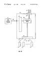
- FIG. 1Aillustrates an embodiment of a mobile simulation system for testing a mobile communications system.
- FIG. 1Bis a block diagram of mobile units, a test control system, and an attenuator matrix in the mobile simulation system of FIG. 1 A.
- FIG. 2is a block diagram of the mobile simulation system of FIG. 1A according to one embodiment of the invention.
- FIG. 3is a block diagram of the mobile simulation system of FIG. 1A according to another embodiment of the invention.
- FIG. 4is a block diagram of an interface card in a mobile unit in the mobile simulation system of FIG. 3 .
- FIG. 5illustrates an attenuator matrix according to one embodiment for use in the mobile simulation system of FIG. 2 or 3 .
- FIG. 6illustrates the attenuator matrix of FIG. 5 used with combiner units to allow more than one mobile unit to be attached to each port of the attenuator matrix.
- FIG. 7illustrates operations performed by the mobile simulation system of FIG. 2 or 3 during initialization.
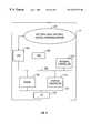
- FIG. 8illustrates operations performed by the mobile simulation system of FIG. 2 or 3 during test operations.
- FIG. 9illustrates an example computer in the mobile simulation system of FIG. 2 or 3 .
- a mobile communications system 26(which may be an analog or digital cellular system or PCS system, for example) includes a number of cells 18 each having a base transceiver station 28 .
- Each base transceiver station 28may include a relatively low-power, multichannel radio transceiver adapted to communicate with mobile units within a cell by radio frequency (RF) or other types of wireless signals.
- the base transceiver stations 28may be coupled to a base system controller (BSC) 20 , which in turn may be coupled to a mobile switching center (MSC) 22 .
- BSCbase system controller
- MSCmobile switching center
- Multiple BSCs 20(each associated with a group of cells 18 ) may be present in the mobile communications system 26 .
- the base transceiver stations 28may be directly coupled to the MSC 22 instead of through BSCs 20 .
- Other types of systems 26may have other different arrangements.
- the MSC 22is adapted to switch calls between mobile units (e.g., mobile telephones or other types of systems or devices capable of mobile communications, such as portable or hand-held computers or devices).
- the MSC 22can also switch calls between a mobile unit and a local telephone coupled through a public switched telephone network (PSTN) 24 .
- PSTNpublic switched telephone network
- the MSC 22controls hand off so that a mobile unit leaving one cell switches automatically to a channel in the next cell.
- the MSC 22receives reports from the base transceiver station 28 on the signal strength of each mobile unit transmitting within the coverage area. From this information, the MSC 22 can decide which of the cells 18 is the appropriate one for each active mobile unit.
- a mobile simulation system 10may be operatively coupled to base transceiver stations 28 in selected cells 18 .
- the mobile simulation system 10includes actual or real mobile units 14 (e.g., mobile telephones or other mobile communications units) that are capable of requesting access to, and communicating in, the mobile communications system 26 .
- the mobile simulation system 10is capable of manipulating the mobile units 14 so that call processing testing may be performed. Effectively, the real mobile units 14 provide the interface from the mobile simulation system 10 into the mobile communications system 26 .
- the mobile units 14are coupled to an attenuator matrix 16 , which may be configured as an M ⁇ N matrix of attenuators (e.g., RF attenuators). Although illustrated with one attenuator matrix 16 , more than one attenuator matrix can be included in the mobile simulation system 10 to connect to more mobile units 14 and more base transceiver stations 28 .
- a first set of cell ports of the M ⁇ N attenuator matrix 16is adapted to connect to M number of base transceiver stations 28 and a second set of mobile ports is adapted to connect to N number of mobile units 14 .
- the matrix 16provides a cross-connected box that has M ⁇ N number of attenuators connecting each of the cell ports to each of the mobile ports.
- the mobile units 14are coupled to a first set of mobile ports 42 over wired links 43 , which may be coaxial cable links in one embodiment.
- the antennas of the mobile units 14may be removed and substituted with a coaxial cable connector to carry RF signals to and from the mobile units 14 .
- the mobile ports 42may include N-type connectors, for example, that allow coaxial cables (or other suitable wires and cables) connected to the antenna ports (or other wireless ports) of the mobile units 14 to connect to an array of attenuators 45 for a closed-loop connection.
- the RF signalsmay be in analog format or digital format, e.g., code division multiple access (CDMA) or time division multiple access (TDMA).
- CDMAcode division multiple access
- TDMAtime division multiple access
- the other side of the attenuator array 45is coupled to a second set of cell ports 40 , which are connected to antennas 47 for wireless communications with base transceiver stations 28 .
- a parallel I/O circuit 49(which may include some type of controller) is adapted to receive control signals from the test control system 12 .
- the output of the parallel input/output (I/O) circuit 49is provided to control the array of attenuators 45 .
- devices other than attenuatorsmay be used to vary strengths of signals transmitted by the mobile units 14 .
- the attenuator matrix 16another type of signal processing device, which may include amplifiers, attenuators, filters, or other types of circuits, may be coupled to the mobile units.
- the signal processing devicemay be an analog or digital device.
- the signal processing devicemay also be implemented in software.
- the MSC 22senses the mobile units 14 as moving when in fact they may be stationary.
- apparent movement patterns of the mobile units 14can be controlled by the mobile simulation system 10 .
- obstructionssuch as buildings or other structures may also be simulated by varying the attenuation of the RF signals.
- Each of the mobile units 14is coupled to a test control system 12 through its I/O port (e.g., serial port or other type of available interface).
- the test control system 12is adapted to send commands to the mobile units 14 to access the mobile communications system 26 .
- the mobile units 14can issue a standard access request to the mobile communications system 26 .
- the test control system 12can further command the mobile units to dial predetermined numbers, and in some embodiments, to send voice data so that voice communications between mobile units 14 through the MSC 22 can be tested.
- the test control system 12controls connection and termination of calls between the mobile units 14 and the mobile communications system 26 . Further, in some embodiments, the test control system 12 may include elements (implementable with software and/or hardware) that are capable of generating and receiving voice data so that the mobile units 14 can be controlled to communicate voice data with one another.
- the attenuator matrix 16is controllable by the test control system 12 to attenuate RF signals transmitted by each of the mobile units 14 so that the base transceiver stations 28 receive attenuated RF signals from the mobile units 14 .
- a mobile unit 14may be made to appear to be moving in a cell 18 .
- the attenuator matrix 16can be controlled so that the signal strength of a given mobile unit 14 is made to appear weakening in one cell and increasing in strength in another cell 18 .
- the mobile unit 14can be made to appear to be moving from one cell 18 to another cell 18 . All this may be done while the mobile units 14 are in fact stationarily positioned, such as in a laboratory or other location.
- the mobile simulation system 10may also be portable so that the simulation system 10 can be moved to different sites for testing different parts of the mobile communications system 26 .
- Using the mobile simulation system 10more movement patterns and greater numbers of mobile units may be tested as compared to conventional test systems. Flexibility in testing is increased since any number of arbitrary patterns may be run by controlling the attenuator matrix 16 to provide different movement patterns of the mobile units 14 . As new components are installed into the mobile communications system 26 , such components can be quickly and conveniently tested using the mobile stimulation system 10 according to some embodiments. By increasing the number of mobile units 14 in the mobile simulation system 10 , the performance threshold of the mobile communications systems 26 (including the MSC 22 and BSC 20 ) can be tested, including its ability to handle large numbers of access requests and maximum capacity for concurrent calls. Further, large numbers of mobile units 14 may be controlled to have different movement patterns in a multi-hour test session to simulate actual traffic conditions. Thus, a wireless test system that includes real mobile units is provided to more accurately test a mobile communications system.
- the test control system 12may be implemented on a platform including Versabus Module European (VME) card cages, which may contain single board computers (SBCs).
- VME card cagesmay include an I/O board having I/O interfaces including SCSI (Small Computer System Interface) ports, network ports, and other ports and interfaces.
- Test control software routinesmay be run on the multiple SBCs.
- a parallel card 108 in the test control system 12may provide ports that connect to one or more control lines 30 to the attenuator matrix 16 .
- other platforms(which may be uniprocessor or multiprocessor systems) may be used to implement the test control system 12 . Such platforms may generally be referred to as controllers in this description.
- the test control system 12may also be coupled to a local area network (LAN) 104 over a link 103 (e.g., an Ethernet link).
- the LAN 104may also be coupled by links 102 to terminal servers 100 that are in turn coupled to I/O ports of the mobile units 14 .
- Each terminal server 100includes an interface for converting signals between the I/O format (e.g., serial format) of the mobile units and the format of the communications links 102 (e.g., Ethernet link).
- the number of mobile units 14 and base transceiver stations 28 shown in FIG. 2are for illustrative purposes only, as they may be varied depending on the number of ports available in the attenuator matrix 16 and the number of attenuator matrices 16 included in the mobile simulation system 10 .
- a first taskmay be an RF matrix interface task (RFMIT) 112 designed to control the attenuator matrix 16 through the parallel card 108 . More than one RFMIT 112 can run in the test control system 12 if multiple attenuator matrices are coupled to the test control system 12 .
- Another task in the test control system 12is the queue driver (QDRV) 110 that provides an interface between a serial mobile interface task (SMIT) 118 and one of the mobile units 14 through the LAN 104 .
- QDRVqueue driver
- the SMIT 118is responsive to instructions (e.g., to initiate, answer, or terminate calls) from other tasks in the test control system 12 to perform the requested operations by issuing corresponding commands through the QDRV task 116 and the LAN 104 to one or more mobile units 14 .
- the SMIT 118is adapted to receive instructions from a traffic generator (TG) task 120 .
- TGtraffic generator
- one SMIT 118corresponds to each mobile unit 14 .
- one SMIT 118can control multiple mobile units 14 , with different SMITs 118 being employed for different types of mobile units 14 (e.g., units of different models or from different manufacturers). Different SMITs 118 may also be provided to support analog and digital mobile systems (e.g., TDMA or CDMA digital systems).
- analog and digital mobile systemse.g., TDMA or CDMA digital systems.
- the traffic generator (TG) task 120“simulates” a mobile subscriber by directing a mobile unit 14 to make and answer calls. Calls may be made according to test case scenarios provided by a user, which may describe a traffic environment for testing. During traffic testing, the TG task 120 issues instructions to step through normal stages of call setup, conversation, and call termination, according to test cases provided to the TG task 120 .
- An air emulation system (AES) task 114is also included in the test control system 12 according to one embodiment.
- the AES task 114primarily manages movement of the mobile units 14 to control positions of the mobile units 14 .
- the AES task 114can control moving mobile units 14 along directed paths at varying speeds, for example.
- the AES task 114is able to emulate the air environment, including emulation of physical obstructions such as buildings and other structures.
- a user interface (UT) task 122(which may be run on a separate workstation 106 or in the test control system 12 ) provides a graphical user interface through which an operator may configure the test control system 12 , monitor test results, and perform various control operations. Multiple user interface tasks may be run on multiple workstations in some embodiments to allow more than one operator access to the mobile simulation system 10 for performing tests. Graphical representations of mobile units 14 (referred to as graphical mobiles) are accessible from the user interface task 122 . Using such graphical mobiles, a call from one mobile unit 14 to another mobile unit 14 can be made and mobile units 14 may be monitored while traffic is running in the test system 12 .
- the user interface task 122also allows an operator to configure movement patterns of the mobile units 14 during testing.
- another user taskreferred to as a plottool task 124 , may be provided to monitor movement of mobile units 14 during testing.
- Movement pattern information (stored in a storage device in the test control system 12 ) of the mobile units 14may be provided by the user interface task 122 to the AES task 114 .
- an operatorcan manipulate movement of mobile units 14 , which are translated into attenuation commands sent over control lines 30 to the attenuator matrix 16 by the AES task 114 through the RFMIT 112 .
- the TG task 120can provide instructions based on test cases to the AES task 114 to perform traffic testing.
- a mobile simulation system 10according to another embodiment is illustrated.
- the test control system 12 in the FIG. 3 embodimenthas speech capability.
- a radio interface card 200includes circuitry to perform tone generation and detection.
- the radio interface card 200can generate voice data to be communicated by a mobile unit 14 and receive voice data from a mobile unit 14 .
- Thisallows the test control system 12 to perform actual voice communications between two mobile units 14 in which voice generated by the radio interface card 200 is transferred to a first mobile unit 14 to be communicated through the attenuator matrix 16 and a base transceiver station 28 to the MSC 22 .
- the voice datamay be received by a second mobile unit 14 , with the received voice data in the second mobile unit 14 transferred to the radio interface card 200 for processing by the test control system 12 .
- the radio interface card 200is coupled to a channel bank 202 over a communications link 204 , which may be T 1 or E 1 link, for example.
- the channel bank 202is coupled to an I/O port of each mobile unit 14 over links 206 .
- each link 206includes a speaker wire 208 and a microphone wire 210 that are both coupled to an interface card 212 that is inside each mobile unit 14 .
- the interface card 212also provides a link to a terminal server 100 .
- Voice data from the radio interface card 200is transmitted through the channel bank 202 and over a microphone wire 210 to the interface card 212 of a mobile unit 14 .
- Voice received by a mobile unit 14is transferred from the interface card 212 over a speaker wire 208 and through the channel bank 202 to the radio interface card 200 .
- the channel bank 202is effectively an interface to convert between T 1 (or E 1 ) signals on link 204 and the speaker and microphone wire signals (digitized voice data) on links 206 .
- the voice data transferred over the link 204 between the radio interface card 200 and the channel bank 202may be time multiplexed, with voice associated with different mobile units 14 transferred in different time slots.
- the radio interface card 200is controlled by the one or more SMITs 118 .
- Voice data received by the radio interface card 200is communicated to the one or more SMITs 118 for processing (e.g., such as to compare output voice data to input voice data and to determine timings of such input and output voice data).
- the attenuator matrix 16includes a cross-connected box of M ⁇ N number of attenuators, each represented as lines connecting cell ports 40 to mobile ports 42 .
- Example attenuators that may be usedare programmable attenuators provided by JFW Industries, Inc., although other types of attenuators may also be used.
- Each attenuator in the matrix 16may be adapted to operate in a frequency range between about 800 and 2,000 megahertz (MHz). Most commercial cellular and PCS systems operate within the stated range. However, it is contemplated that, in further embodiments, the attenuators may be made to operate at higher or lower frequencies.
- Each connection between a cell port 40 and a mobile port 42contains its own attenuator.
- 18 connections(and thus 18 attenuators) exist between the cell ports 40 and mobile ports 42 in the matrix 16 .
- the mobile simulation system 10controls attenuation of the RF link between a mobile unit 14 and a base transceiver system 28 with the attenuator matrix 16 . Adjusting the attenuation simulates the distance of a mobile unit 14 from an antenna of a base transceiver system 28 .
- the MSC 22perceives the mobile units 14 as moving (even though the mobile units 14 may not actually have moved).
- the matrix 16may allow more than one mobile unit to be attenuated on the same mobile port 42 .
- thismay be performed by using a combiner unit 50 to which multiple mobile units 14 are connected to.
- Each combiner unit 50is basically a splitter that provides a 1-to-N connector (e.g., an SMA connector) which takes a single signal on one side and splits it into N signals on the other side of the unit.
- the connectorprovides a bi-directional signal link in which a signal is split in one direction and signals are combined in the opposite direction.
- multiple combiner units 50as illustrated in FIG. 6, with many connected to multiple mobile units 14 , a greater amount of traffic can be generated during testing.
- movement of multiple mobile units 14 attached to a combiner unit 50involves moving all the mobile units 14 along the same patterns and at the same speed.
- FIGS. 7-8flows between the various software tasks in the test control system 12 during test operations are illustrated. Operations may be performed in the form of messaging between tasks of the test control system 12 .
- FIG. 7illustrates the initialization of the test control system 12 . From the user interface task 122 , the number of mobile units and movement patterns and speeds may be specified (either by an operator or using default settings) and provided to the TG task 120 . Also during initialization, the user interface task 122 provides the number of cells, placement and locations of cells, and cell types to the AES task 114 . Further, the user interface task 122 may provide security information to the SMIT 118 and the number of mobile and cell ports of the attenuator matrix 16 to the RFMIT 112 .
- trafficmay be started. As illustrated in FIG. 8, this may be started by the user interface task 122 issuing a Start_Traffic message to the TG task 120 .
- the TG taskcan then send a Start_Move message to the AES task 114 to request that the AES task 114 start the movement of mobile units 14 .
- the TG task 120may also issue various operations to be performed by the mobile units 14 by sending corresponding messages to SMITs 118 .
- one SMIT 118may be provided for each mobile unit 14 .
- such messagesmay include the following: Originate_Call (to originate a call through the MSC 22 ); Answer_Call (to answer an incoming call, either from another mobile unit 14 or from some other source); and Tone_Send (to send a tone, such as that associated with pressing of a numeric key on the mobile unit 14 ).
- the AES task 114also provides messages containing connection information to the SMITs 118 in the test control system 12 .
- Connection informationmay include the cell and sector that each mobile unit 14 is located in, services available, and so forth.
- the SMITs 118transmit command messages to the mobile units 14 through respective QDRV tasks 116 .
- the SMITs 118in addition to the command messages, may also send vendor serial numbers of the mobile units 14 .
- Such serial numbersmay be dynamically assigned to the mobile units 14 so that different types of services may be associated with the mobile units (e.g., analog, digital, and so forth). Additionally, the serial number may be assigned so that a mobile unit 14 may be one identified to be roaming in the mobile communication system under test.
- the AES tasksends messages of desired movements (in the form of attenuation messages) to the RFMIT 112 .
- the attenuation messagesmay specify the amount of attenuation for each attenuator in the matrix 16 .
- the attenuation messagesare translated or converted to attenuation control signals that are sent by the RFMIT 112 to the attenuator matrix 16 to control attenuation of RF signals from the mobile units 14 .
- a incoming call to a mobile unit 14is communicated by that mobile unit 14 through a terminal server 100 , the LAN 104 , a QDRV task 116 , and an SMIT 118 to the TG task 120 .
- the TG task 120can instruct the SMIT 118 to answer the call by issuing an Answer_Call message.
- a flow similar to the FIG. 8 flowmay be used, with a Stop_Traffic message issued by the user interface task 122 instead of the Start_Traffic message to the TG task 120 .
- the TG task 120responds by issuing a Stop_Movement message to the AES task 114 as well as issuing Terminate_Call messages to the SMITs 118 .
- the SMITs 118convert the Terminate_Call messages into commands that may be understood by the mobile units 14 to terminate a call.
- a mobile simulation systemincludes real mobile units that are controllable by the mobile simulation system to access, and communicate in, a mobile communications system that is under test.
- Attenuatorsare adapted to receive RF signal transmissions of the mobile units through closed loop connections (e.g., coaxial cables).
- the attenuators(or other type of signal processing device) are controllable to vary the strengths of RF signals of the mobile units, with the attenuated RF signals communicated from antennas coupled to the attenuator matrix 16 to base transceiver stations. Variations of the attenuation of RF signals of the mobile units are performed to simulate movement of the mobile units in a cell or between cells, even though they may be stationary.
- accesses to the mobile communications systemcan be performed while the mobile units are “moving” to emulate traffic conditions.
- a controllerwhich may be a computer, for example, in the test control system 12 is illustrated. It is contemplated that computers or other controllers used in the test control system 12 may have other arrangements and architectures in further embodiments.
- a central processing unit (CPU) 300may be coupled to a system bus 308 as well as to main memory 304 .
- the various software tasks, routines, device drivers, and operating system, collectively referred to as 302may be executable on the CPU 300 .
- multiple CPUs 300may be present in the test control system 12 .
- the components illustratedmay be repeated to correspond to the multiple controllers.
- a network controller 310may be coupled to the system bus 308 for connection to a network such as the LAN 104 .
- a bridge controller 306may couple the system bus 308 to a secondary bus 314 .
- One or more I/O circuits 316may be coupled to the secondary bus 314 .
- Storage media suitable for tangibly embodying software instructionsmay include different forms of memory including semiconductor devices such as dynamic or static random access memory, erasable and programmable read-only memories (EPROMs), electrically erasable and programmable read-only memories (EEPROMs), and flash memories; magnetic disks such as fixed, floppy and removable disks; other magnetic media including tapes; and optical media such as CD or DVD disks.
- semiconductor devicessuch as dynamic or static random access memory, erasable and programmable read-only memories (EPROMs), electrically erasable and programmable read-only memories (EEPROMs), and flash memories
- magnetic diskssuch as fixed, floppy and removable disks
- optical mediasuch as CD or DVD disks.
- the softwarecan be loaded into the system 12 in one of many different ways. For example, instructions or other code segments stored on one or more storage media transported through a network interface card, modem, or other interface mechanism may be loaded into the system 12 and executed to perform programmed acts. In the loading or transport process, data signals that are embodied as carrier waves (transmitted over telephone lines, network lines, wireless links, cables and the like) may communicate the instructions or code the segments to the system 12 .
- instructions or other code segments stored on one or more storage media transported through a network interface card, modem, or other interface mechanismmay be loaded into the system 12 and executed to perform programmed acts.
- data signalsthat are embodied as carrier waves (transmitted over telephone lines, network lines, wireless links, cables and the like) may communicate the instructions or code the segments to the system 12 .
Landscapes
- Engineering & Computer Science (AREA)
- Computer Networks & Wireless Communication (AREA)
- Signal Processing (AREA)
- Mobile Radio Communication Systems (AREA)
Abstract
Description
Claims (27)
Priority Applications (1)
| Application Number | Priority Date | Filing Date | Title |
|---|---|---|---|
| US09/312,950US6272337B1 (en) | 1999-05-17 | 1999-05-17 | Testing a mobile communications system |
Applications Claiming Priority (1)
| Application Number | Priority Date | Filing Date | Title |
|---|---|---|---|
| US09/312,950US6272337B1 (en) | 1999-05-17 | 1999-05-17 | Testing a mobile communications system |
Publications (1)
| Publication Number | Publication Date |
|---|---|
| US6272337B1true US6272337B1 (en) | 2001-08-07 |
Family
ID=23213725
Family Applications (1)
| Application Number | Title | Priority Date | Filing Date |
|---|---|---|---|
| US09/312,950Expired - LifetimeUS6272337B1 (en) | 1999-05-17 | 1999-05-17 | Testing a mobile communications system |
Country Status (1)
| Country | Link |
|---|---|
| US (1) | US6272337B1 (en) |
Cited By (41)
| Publication number | Priority date | Publication date | Assignee | Title |
|---|---|---|---|---|
| US20020009992A1 (en)* | 2000-07-10 | 2002-01-24 | Eric Jensen | Wireless system signal propagation collection and analysis |
| US20020119772A1 (en)* | 2001-02-26 | 2002-08-29 | Nec Corporation | Base station testing apparatus and method for testing a base station in a CDMA communication system |
| US20030137339A1 (en)* | 2001-11-23 | 2003-07-24 | Gilbert Gloaguen | Switching device provided with integrated test means |
| US20030156549A1 (en)* | 2002-01-09 | 2003-08-21 | Robert Binder | Method and system for evaluating wireless applications |
| WO2003075590A1 (en)* | 2002-03-06 | 2003-09-12 | Ifr Limited | Testing mobile telephone terminals |
| EP1432258A1 (en)* | 2002-12-18 | 2004-06-23 | Mitsubishi Electric Information Technology Centre Europe B.V. | Device for an accurate testing of one or several transceivers |
| US20050003763A1 (en)* | 2003-07-03 | 2005-01-06 | Rotani, Inc. | Methods and apparatus for high throughput multiple radio wireless cells and networks |
| US20050064864A1 (en)* | 2003-09-22 | 2005-03-24 | United Parcel Service Of America, Inc. | Symbiotic system for testing electromagnetic signal coverage in areas near transport routes |
| US20050075105A1 (en)* | 2003-09-24 | 2005-04-07 | United Parcel Service Of America, Inc. | Rapid exchange system for testing wireless networks |
| US20050101268A1 (en)* | 2003-09-22 | 2005-05-12 | United Parcel Service Of America, Inc. | Network testing systems and methods |
| US6915128B1 (en)* | 2001-02-13 | 2005-07-05 | Sprint Spectrum L.P. | Method and system for monitoring a wireless communications network |
| US7010295B1 (en)* | 2001-04-25 | 2006-03-07 | Sprint Spectrum L.P. | Method and system for automatic testing of network elements |
| US20060049321A1 (en)* | 2004-09-02 | 2006-03-09 | United Parcel Service Of America, Inc. | Rapid exchange system for testing wireless networks |
| US20060164320A1 (en)* | 2005-01-21 | 2006-07-27 | Rotani, Inc. | Method and apparatus for an antenna module |
| US7099295B1 (en)* | 1999-08-27 | 2006-08-29 | Psion Teklogix, Inc. | Apparatus and method for bridging a wired network and wireless devices |
| US7110768B1 (en)* | 1999-12-06 | 2006-09-19 | Avaya Technology Corp. | Measurement and antenna placement tool for establishing a cell site |
| US20060246843A1 (en)* | 2002-12-20 | 2006-11-02 | Taavi Hirvonen | Method and arrangement for testing a radio device |
| US20060270351A1 (en)* | 2004-06-15 | 2006-11-30 | Rotani, Inc. | Method and apparatus for increasing data throughput |
| US20070121553A1 (en)* | 2005-11-28 | 2007-05-31 | Yoon Young C | Reverse link load estimation using reference signal |
| US20070202809A1 (en)* | 2006-02-28 | 2007-08-30 | Rotani, Inc. | Methods and apparatus for overlapping MIMO antenna physical sectors |
| US20070270195A1 (en)* | 2006-05-19 | 2007-11-22 | Hon Hai Precision Industry Co., Ltd. | Roaming function test system and method |
| US20080024323A1 (en)* | 2006-07-25 | 2008-01-31 | Nagesh Kadaba | systems and methods for monitoring travel conditions |
| US20080150827A1 (en)* | 2004-07-19 | 2008-06-26 | Rotani, Inc. | Method And Apparatus For Shaped Antenna Radiation Patterns |
| US7623855B1 (en)* | 2005-12-06 | 2009-11-24 | Sprint Communications Company L.P. | Sustainable wireless service testing |
| US20100016031A1 (en)* | 2005-02-14 | 2010-01-21 | Patton John D | Telephone and telephone accessory signal generator and methods and devices using the same |
| CN101080084B (en)* | 2006-05-24 | 2010-05-26 | 鸿富锦精密工业(深圳)有限公司 | Roaming function testing system, device and method |
| US20100172244A1 (en)* | 2005-04-21 | 2010-07-08 | Mlinarsky I Fanny | Simulating time-varying conditions in a wireless network |
| US20100269722A1 (en)* | 2008-01-31 | 2010-10-28 | Patria Land & Armament Oy | Support member for supporting shell, and method |
| CN101034936B (en)* | 2007-02-09 | 2010-11-10 | 华为技术有限公司 | Data configuration method, device and system of radio network controller |
| CN101087450B (en)* | 2006-06-09 | 2010-12-15 | 株式会社日立制作所 | Wireless basic station testing device |
| WO2012003447A2 (en) | 2010-07-02 | 2012-01-05 | T-Mobile Usa, Inc. | Switching matrix and test platform |
| US8416067B2 (en) | 2008-09-09 | 2013-04-09 | United Parcel Service Of America, Inc. | Systems and methods for utilizing telematics data to improve fleet management operations |
| US8606262B1 (en) | 2012-02-16 | 2013-12-10 | The Board Room, Inc. | Testing or recording system for a mobile telephone |
| US9208626B2 (en) | 2011-03-31 | 2015-12-08 | United Parcel Service Of America, Inc. | Systems and methods for segmenting operational data |
| US9805521B1 (en) | 2013-12-03 | 2017-10-31 | United Parcel Service Of America, Inc. | Systems and methods for assessing turns made by a vehicle |
| US9913147B2 (en) | 2012-10-05 | 2018-03-06 | Andrew Wireless Systems Gmbh | Capacity optimization sub-system for distributed antenna system |
| US10136345B2 (en) | 2012-02-07 | 2018-11-20 | Entit Software Llc | Testing a mobile application |
| US10309788B2 (en) | 2015-05-11 | 2019-06-04 | United Parcel Service Of America, Inc. | Determining street segment headings |
| US10530907B1 (en)* | 1996-12-16 | 2020-01-07 | Rekha K Rao | Wireless device communication system |
| US10713860B2 (en) | 2011-03-31 | 2020-07-14 | United Parcel Service Of America, Inc. | Segmenting operational data |
| US11482058B2 (en) | 2008-09-09 | 2022-10-25 | United Parcel Service Of America, Inc. | Systems and methods for utilizing telematics data to improve fleet management operations |
Citations (11)
| Publication number | Priority date | Publication date | Assignee | Title |
|---|---|---|---|---|
| US5828962A (en)* | 1996-04-18 | 1998-10-27 | France Telecom | Process for analyzing traffic localization within a cellular radiocommunication network |
| US5875400A (en) | 1995-04-18 | 1999-02-23 | Northern Telecom Limited | Cellular mobile communications system |
| US5884177A (en) | 1995-10-25 | 1999-03-16 | Northern Telecom Limited | Cellular communication system and method providing improved handoff capability |
| US5943014A (en)* | 1996-06-06 | 1999-08-24 | Qualcom Incorporated | Using a signal with increased power for determining the position of a mobile subscriber in a CDMA cellular telephone system |
| US5953669A (en)* | 1997-12-11 | 1999-09-14 | Motorola, Inc. | Method and apparatus for predicting signal characteristics in a wireless communication system |
| US5983106A (en)* | 1996-12-18 | 1999-11-09 | Nortel Networks Corporation | Method and apparatus for minimizing the number of samples needed to determine cell radius coverage contour reliability in a radiotelephone system |
| US6006089A (en)* | 1996-03-06 | 1999-12-21 | Leader Electronics Corp. | System and method of measuring electric field strength |
| US6052583A (en)* | 1997-05-29 | 2000-04-18 | Northern Telecom Limited | Methods and systems for selecting drive routes for testing RF coverage in a radiotelephone system |
| US6088582A (en)* | 1997-07-16 | 2000-07-11 | International Business Machines Corp. | Controlled environment radio test apparatus and method |
| US6119010A (en)* | 1998-10-13 | 2000-09-12 | Motorola, Inc. | Method and apparatus for adjusting channel powers in a wireless communication system based on a predicted mobile location |
| US6169896B1 (en)* | 1997-03-12 | 2001-01-02 | Emerald Bay Systems, Inc. | System for evaluating communication network services |
- 1999
- 1999-05-17USUS09/312,950patent/US6272337B1/ennot_activeExpired - Lifetime
Patent Citations (11)
| Publication number | Priority date | Publication date | Assignee | Title |
|---|---|---|---|---|
| US5875400A (en) | 1995-04-18 | 1999-02-23 | Northern Telecom Limited | Cellular mobile communications system |
| US5884177A (en) | 1995-10-25 | 1999-03-16 | Northern Telecom Limited | Cellular communication system and method providing improved handoff capability |
| US6006089A (en)* | 1996-03-06 | 1999-12-21 | Leader Electronics Corp. | System and method of measuring electric field strength |
| US5828962A (en)* | 1996-04-18 | 1998-10-27 | France Telecom | Process for analyzing traffic localization within a cellular radiocommunication network |
| US5943014A (en)* | 1996-06-06 | 1999-08-24 | Qualcom Incorporated | Using a signal with increased power for determining the position of a mobile subscriber in a CDMA cellular telephone system |
| US5983106A (en)* | 1996-12-18 | 1999-11-09 | Nortel Networks Corporation | Method and apparatus for minimizing the number of samples needed to determine cell radius coverage contour reliability in a radiotelephone system |
| US6169896B1 (en)* | 1997-03-12 | 2001-01-02 | Emerald Bay Systems, Inc. | System for evaluating communication network services |
| US6052583A (en)* | 1997-05-29 | 2000-04-18 | Northern Telecom Limited | Methods and systems for selecting drive routes for testing RF coverage in a radiotelephone system |
| US6088582A (en)* | 1997-07-16 | 2000-07-11 | International Business Machines Corp. | Controlled environment radio test apparatus and method |
| US5953669A (en)* | 1997-12-11 | 1999-09-14 | Motorola, Inc. | Method and apparatus for predicting signal characteristics in a wireless communication system |
| US6119010A (en)* | 1998-10-13 | 2000-09-12 | Motorola, Inc. | Method and apparatus for adjusting channel powers in a wireless communication system based on a predicted mobile location |
Non-Patent Citations (1)
| Title |
|---|
| CDMA Development Group, "Multiple Access Wireless Communications"; pp. 1-3; dated at least as early as Mar. 24, 1999 and printed from http://www.cdg.org/tech/a13 ross/MultipleAccess.html. |
Cited By (127)
| Publication number | Priority date | Publication date | Assignee | Title |
|---|---|---|---|---|
| US10530907B1 (en)* | 1996-12-16 | 2020-01-07 | Rekha K Rao | Wireless device communication system |
| US7099295B1 (en)* | 1999-08-27 | 2006-08-29 | Psion Teklogix, Inc. | Apparatus and method for bridging a wired network and wireless devices |
| US7110768B1 (en)* | 1999-12-06 | 2006-09-19 | Avaya Technology Corp. | Measurement and antenna placement tool for establishing a cell site |
| US20020009992A1 (en)* | 2000-07-10 | 2002-01-24 | Eric Jensen | Wireless system signal propagation collection and analysis |
| US7853267B2 (en)* | 2000-07-10 | 2010-12-14 | Andrew Llc | Wireless system signal propagation collection and analysis |
| US6915128B1 (en)* | 2001-02-13 | 2005-07-05 | Sprint Spectrum L.P. | Method and system for monitoring a wireless communications network |
| US20020119772A1 (en)* | 2001-02-26 | 2002-08-29 | Nec Corporation | Base station testing apparatus and method for testing a base station in a CDMA communication system |
| US7010295B1 (en)* | 2001-04-25 | 2006-03-07 | Sprint Spectrum L.P. | Method and system for automatic testing of network elements |
| US6801081B2 (en)* | 2001-11-23 | 2004-10-05 | Koninklijke Philips Electronics N.V. | Switching device provided with integrated test means |
| CN100342239C (en)* | 2001-11-23 | 2007-10-10 | Nxp股份有限公司 | Switch equipment provided with integrated tester |
| US20030137339A1 (en)* | 2001-11-23 | 2003-07-24 | Gilbert Gloaguen | Switching device provided with integrated test means |
| US7339891B2 (en)* | 2002-01-09 | 2008-03-04 | Mverify Corporation | Method and system for evaluating wireless applications |
| US20030156549A1 (en)* | 2002-01-09 | 2003-08-21 | Robert Binder | Method and system for evaluating wireless applications |
| US20050118957A1 (en)* | 2002-03-06 | 2005-06-02 | Flitton Gregory T. | Testing mobile telephone terminals |
| WO2003075590A1 (en)* | 2002-03-06 | 2003-09-12 | Ifr Limited | Testing mobile telephone terminals |
| EP1432258A1 (en)* | 2002-12-18 | 2004-06-23 | Mitsubishi Electric Information Technology Centre Europe B.V. | Device for an accurate testing of one or several transceivers |
| US20060246843A1 (en)* | 2002-12-20 | 2006-11-02 | Taavi Hirvonen | Method and arrangement for testing a radio device |
| US7680463B2 (en)* | 2002-12-20 | 2010-03-16 | Jot Automation Oy | Method and arrangement for testing a radio device |
| US7359675B2 (en) | 2003-07-03 | 2008-04-15 | Rotani, Inc. | Methods and apparatus for high throughput multiple radio wireless cells and networks |
| US7305246B2 (en) | 2003-07-03 | 2007-12-04 | Rotani, Inc. | Method and apparatus for high throughput multiple radio sectorized wireless cell |
| WO2005010652A3 (en)* | 2003-07-03 | 2006-03-30 | Rotani Inc | Method and apparatus for high throughput multiple radio sectorized wireless cell |
| US20080132260A1 (en)* | 2003-07-03 | 2008-06-05 | Rotani, Inc. | Methods and Apparatus for Wireless Network Formation |
| US20080137616A1 (en)* | 2003-07-03 | 2008-06-12 | Rotani, Inc. | Methods and apparatus for reducing interference |
| US7424298B2 (en) | 2003-07-03 | 2008-09-09 | Rotani, Inc. | Methods and apparatus for channel assignment |
| US7308270B2 (en) | 2003-07-03 | 2007-12-11 | Rotani, Inc. | Method and apparatus for high throughput multiple radio sectorized wireless cell |
| US20080132261A1 (en)* | 2003-07-03 | 2008-06-05 | Rotani, Inc. | Methods and Apparatus for Channel Assignment |
| US7302278B2 (en)* | 2003-07-03 | 2007-11-27 | Rotani, Inc. | Method and apparatus for high throughput multiple radio sectorized wireless cell |
| US20070066234A1 (en)* | 2003-07-03 | 2007-03-22 | Rotani, Inc. | Method and apparatus for high throughput multiple radio sectorized wireless cell |
| US20050282545A1 (en)* | 2003-07-03 | 2005-12-22 | Rotani, Inc. | Method and apparatus for high throughput multiple radio sectorized wireless cell |
| US20050003865A1 (en)* | 2003-07-03 | 2005-01-06 | Roc Lastinger | Method and apparatus for high throughput multiple radio sectorized wireless cell |
| US7274944B2 (en) | 2003-07-03 | 2007-09-25 | Rotani, Inc. | Method and apparatus for high throughput multiple radio sectorized wireless cell |
| US20050003763A1 (en)* | 2003-07-03 | 2005-01-06 | Rotani, Inc. | Methods and apparatus for high throughput multiple radio wireless cells and networks |
| US8374597B2 (en) | 2003-09-22 | 2013-02-12 | United Parcel Service Of America, Inc. | Symbiotic system for testing electromagnetic signal coverage in areas near transport routes |
| US20050101268A1 (en)* | 2003-09-22 | 2005-05-12 | United Parcel Service Of America, Inc. | Network testing systems and methods |
| US20110039498A1 (en)* | 2003-09-22 | 2011-02-17 | United Parcel Service Of America, Inc. | Symbiotic system for testing electromagnetic signal coverage in areas near transport routes |
| US20050064864A1 (en)* | 2003-09-22 | 2005-03-24 | United Parcel Service Of America, Inc. | Symbiotic system for testing electromagnetic signal coverage in areas near transport routes |
| US8948742B2 (en) | 2003-09-22 | 2015-02-03 | United Parcel Service Of America, Inc. | Symbiotic system for testing electromagnetic signal coverage in areas near transport routes |
| US7660577B2 (en) | 2003-09-22 | 2010-02-09 | United Parcel Service Of America, Inc. | Network testing systems and methods |
| US7773985B2 (en) | 2003-09-22 | 2010-08-10 | United Parcel Service Of America, Inc. | Symbiotic system for testing electromagnetic signal coverage in areas near transport routes |
| US8768342B2 (en) | 2003-09-22 | 2014-07-01 | United Parcel Service Of America, Inc. | Symbiotic system for testing electromagnetic signal coverage in areas near transport routes |
| US20050075006A1 (en)* | 2003-09-24 | 2005-04-07 | United Parcel Service Of America, Inc. | Rapid exchange system for testing wireless networks |
| US7431245B2 (en) | 2003-09-24 | 2008-10-07 | United Parcel Service Of America, Inc. | Rapid exchange system for testing wireless networks |
| US20050082077A1 (en)* | 2003-09-24 | 2005-04-21 | United Parcel Service Of America, Inc. | Rapid exchange system for testing wireless networks |
| US20050072888A1 (en)* | 2003-09-24 | 2005-04-07 | United Parcel Service Of America, Inc. | Rapid exchange system for testing wireless networks |
| US20050075105A1 (en)* | 2003-09-24 | 2005-04-07 | United Parcel Service Of America, Inc. | Rapid exchange system for testing wireless networks |
| US7059897B2 (en) | 2003-09-24 | 2006-06-13 | United Parcel Service Of America, Inc. | Rapid exchange system for testing wireless networks |
| US20060270351A1 (en)* | 2004-06-15 | 2006-11-30 | Rotani, Inc. | Method and apparatus for increasing data throughput |
| US7400860B2 (en) | 2004-06-15 | 2008-07-15 | Rotani, Inc. | Method and apparatus for increasing data throughput |
| US20080242230A1 (en)* | 2004-06-15 | 2008-10-02 | Rotani, Inc. | Method and Apparatus for Increasing Data Throughput |
| US7822386B2 (en) | 2004-06-15 | 2010-10-26 | Rotani, Inc. | Method and apparatus for increasing data throughput |
| US7616959B2 (en) | 2004-07-19 | 2009-11-10 | Rotani, Inc. | Method and apparatus for shaped antenna radiation patterns |
| US20080150827A1 (en)* | 2004-07-19 | 2008-06-26 | Rotani, Inc. | Method And Apparatus For Shaped Antenna Radiation Patterns |
| US7552901B2 (en) | 2004-09-02 | 2009-06-30 | United Parcel Service Of America, Inc. | Rapid exchange system for testing wireless networks |
| US20060049321A1 (en)* | 2004-09-02 | 2006-03-09 | United Parcel Service Of America, Inc. | Rapid exchange system for testing wireless networks |
| US7489282B2 (en) | 2005-01-21 | 2009-02-10 | Rotani, Inc. | Method and apparatus for an antenna module |
| US20060164320A1 (en)* | 2005-01-21 | 2006-07-27 | Rotani, Inc. | Method and apparatus for an antenna module |
| US20100016031A1 (en)* | 2005-02-14 | 2010-01-21 | Patton John D | Telephone and telephone accessory signal generator and methods and devices using the same |
| US20100172244A1 (en)* | 2005-04-21 | 2010-07-08 | Mlinarsky I Fanny | Simulating time-varying conditions in a wireless network |
| US8116758B2 (en)* | 2005-04-21 | 2012-02-14 | Azimuth Systems, Inc. | Simulating time-varying conditions in a wireless network |
| US7701910B2 (en)* | 2005-11-28 | 2010-04-20 | Telefonaktiebolaget Lm Ericsson (Publ) | Reverse link load estimation using reference signal |
| US20070121553A1 (en)* | 2005-11-28 | 2007-05-31 | Yoon Young C | Reverse link load estimation using reference signal |
| US7623855B1 (en)* | 2005-12-06 | 2009-11-24 | Sprint Communications Company L.P. | Sustainable wireless service testing |
| US9525468B2 (en) | 2006-02-28 | 2016-12-20 | Woodbury Wireless, LLC | Methods and apparatus for overlapping MIMO physical sectors |
| US8325695B2 (en) | 2006-02-28 | 2012-12-04 | Rotani, Inc. | Methods and apparatus for overlapping MIMO physical sectors |
| US9496930B2 (en) | 2006-02-28 | 2016-11-15 | Woodbury Wireless, LLC | Methods and apparatus for overlapping MIMO physical sectors |
| US8009646B2 (en) | 2006-02-28 | 2011-08-30 | Rotani, Inc. | Methods and apparatus for overlapping MIMO antenna physical sectors |
| US20110230141A1 (en)* | 2006-02-28 | 2011-09-22 | Rotani, Inc. | Methods and Apparatus for Overlapping MIMO Antenna Physical Sectors |
| US20110228870A1 (en)* | 2006-02-28 | 2011-09-22 | Rotani, Inc. | Method and Apparatus for Overlapping MIMO Physical Sectors |
| US12015457B2 (en) | 2006-02-28 | 2024-06-18 | Woodbury Wireless, LLC | MIMO methods and systems |
| US10063297B1 (en) | 2006-02-28 | 2018-08-28 | Woodbury Wireless, LLC | MIMO methods and systems |
| US8111678B2 (en) | 2006-02-28 | 2012-02-07 | Rotani, Inc. | Methods and apparatus for overlapping MIMO antenna physical sectors |
| US9503163B2 (en) | 2006-02-28 | 2016-11-22 | Woodbury Wireless, LLC | Methods and apparatus for overlapping MIMO physical sectors |
| US8270383B2 (en) | 2006-02-28 | 2012-09-18 | Rotani, Inc. | Methods and apparatus for overlapping MIMO physical sectors |
| US10516451B2 (en) | 2006-02-28 | 2019-12-24 | Woodbury Wireless Llc | MIMO methods |
| US8345651B2 (en) | 2006-02-28 | 2013-01-01 | Rotani, Inc. | Methods and apparatus for overlapping MIMO antenna physical sectors |
| US9496931B2 (en) | 2006-02-28 | 2016-11-15 | Woodbury Wireless, LLC | Methods and apparatus for overlapping MIMO physical sectors |
| US10069548B2 (en) | 2006-02-28 | 2018-09-04 | Woodbury Wireless, LLC | Methods and apparatus for overlapping MIMO physical sectors |
| US8428039B2 (en) | 2006-02-28 | 2013-04-23 | Rotani, Inc. | Methods and apparatus for overlapping MIMO physical sectors |
| US11108443B2 (en) | 2006-02-28 | 2021-08-31 | Woodbury Wireless, LLC | MIMO methods and systems |
| US9584197B2 (en) | 2006-02-28 | 2017-02-28 | Woodbury Wireless, LLC | Methods and apparatus for overlapping MIMO physical sectors |
| US20070202809A1 (en)* | 2006-02-28 | 2007-08-30 | Rotani, Inc. | Methods and apparatus for overlapping MIMO antenna physical sectors |
| US10211895B2 (en) | 2006-02-28 | 2019-02-19 | Woodbury Wireless Llc | MIMO methods and systems |
| US8855089B2 (en) | 2006-02-28 | 2014-10-07 | Helvetia Ip Ag | Methods and apparatus for overlapping MIMO physical sectors |
| US20070270195A1 (en)* | 2006-05-19 | 2007-11-22 | Hon Hai Precision Industry Co., Ltd. | Roaming function test system and method |
| CN101080084B (en)* | 2006-05-24 | 2010-05-26 | 鸿富锦精密工业(深圳)有限公司 | Roaming function testing system, device and method |
| CN101087450B (en)* | 2006-06-09 | 2010-12-15 | 株式会社日立制作所 | Wireless basic station testing device |
| US20080024323A1 (en)* | 2006-07-25 | 2008-01-31 | Nagesh Kadaba | systems and methods for monitoring travel conditions |
| US7554440B2 (en) | 2006-07-25 | 2009-06-30 | United Parcel Service Of America, Inc. | Systems and methods for monitoring travel conditions |
| CN101034936B (en)* | 2007-02-09 | 2010-11-10 | 华为技术有限公司 | Data configuration method, device and system of radio network controller |
| US20100269722A1 (en)* | 2008-01-31 | 2010-10-28 | Patria Land & Armament Oy | Support member for supporting shell, and method |
| US10540830B2 (en) | 2008-09-09 | 2020-01-21 | United Parcel Service Of America, Inc. | Systems and methods for utilizing telematics data to improve fleet management operations |
| US9472030B2 (en) | 2008-09-09 | 2016-10-18 | United Parcel Service Of America, Inc. | Systems and methods for utilizing telematics data to improve fleet management operations |
| US9324198B2 (en) | 2008-09-09 | 2016-04-26 | United Parcel Service Of America, Inc. | Systems and methods for utilizing telematics data to improve fleet management operations |
| US10192370B2 (en) | 2008-09-09 | 2019-01-29 | United Parcel Service Of America, Inc. | Systems and methods for utilizing telematics data to improve fleet management operations |
| US8896430B2 (en) | 2008-09-09 | 2014-11-25 | United Parcel Service Of America, Inc. | Systems and methods for utilizing telematics data to improve fleet management operations |
| US9704303B2 (en) | 2008-09-09 | 2017-07-11 | United Parcel Service Of America, Inc. | Systems and methods for utilizing telematics data to improve fleet management operations |
| US8416067B2 (en) | 2008-09-09 | 2013-04-09 | United Parcel Service Of America, Inc. | Systems and methods for utilizing telematics data to improve fleet management operations |
| US11482058B2 (en) | 2008-09-09 | 2022-10-25 | United Parcel Service Of America, Inc. | Systems and methods for utilizing telematics data to improve fleet management operations |
| EP2589236A4 (en)* | 2010-07-02 | 2017-01-18 | T-Mobile USA, Inc. | Switching matrix and test platform |
| CN103168485B (en)* | 2010-07-02 | 2017-04-12 | T移动美国公司 | Switching matrix and test platform |
| WO2012003447A2 (en) | 2010-07-02 | 2012-01-05 | T-Mobile Usa, Inc. | Switching matrix and test platform |
| US20120003982A1 (en)* | 2010-07-02 | 2012-01-05 | T-Mobile Usa, Inc. | Switching Matrix and Test Platform |
| CN103168485A (en)* | 2010-07-02 | 2013-06-19 | T移动美国公司 | Switching matrix and test platform |
| JP2013535874A (en)* | 2010-07-02 | 2013-09-12 | ティー−モバイル ユーエスエイ インコーポレイテッド | Switch matrix and test platform |
| US9143961B2 (en)* | 2010-07-02 | 2015-09-22 | T-Mobile Usa, Inc. | Switching matrix and test platform |
| US9613468B2 (en) | 2011-03-31 | 2017-04-04 | United Parcel Service Of America, Inc. | Systems and methods for updating maps based on telematics data |
| US9903734B2 (en) | 2011-03-31 | 2018-02-27 | United Parcel Service Of America, Inc. | Systems and methods for updating maps based on telematics data |
| US11727339B2 (en) | 2011-03-31 | 2023-08-15 | United Parcel Service Of America, Inc. | Systems and methods for updating maps based on telematics data |
| US9256992B2 (en) | 2011-03-31 | 2016-02-09 | United Parcel Service Of America, Inc. | Systems and methods for assessing vehicle handling |
| US9208626B2 (en) | 2011-03-31 | 2015-12-08 | United Parcel Service Of America, Inc. | Systems and methods for segmenting operational data |
| US10267642B2 (en) | 2011-03-31 | 2019-04-23 | United Parcel Service Of America, Inc. | Systems and methods for assessing vehicle and vehicle operator efficiency |
| US11670116B2 (en) | 2011-03-31 | 2023-06-06 | United Parcel Service Of America, Inc. | Segmenting operational data |
| US9858732B2 (en) | 2011-03-31 | 2018-01-02 | United Parcel Service Of America, Inc. | Systems and methods for assessing vehicle and vehicle operator efficiency |
| US11157861B2 (en) | 2011-03-31 | 2021-10-26 | United Parcel Service Of America, Inc. | Systems and methods for updating maps based on telematics data |
| US9799149B2 (en) | 2011-03-31 | 2017-10-24 | United Parcel Service Of America, Inc. | Fleet management computer system for providing a fleet management user interface displaying vehicle and operator data on a geographical map |
| US10748353B2 (en) | 2011-03-31 | 2020-08-18 | United Parcel Service Of America, Inc. | Segmenting operational data |
| US10563999B2 (en) | 2011-03-31 | 2020-02-18 | United Parcel Service Of America, Inc. | Systems and methods for assessing operational data for a vehicle fleet |
| US10713860B2 (en) | 2011-03-31 | 2020-07-14 | United Parcel Service Of America, Inc. | Segmenting operational data |
| US10692037B2 (en) | 2011-03-31 | 2020-06-23 | United Parcel Service Of America, Inc. | Systems and methods for updating maps based on telematics data |
| US10136345B2 (en) | 2012-02-07 | 2018-11-20 | Entit Software Llc | Testing a mobile application |
| US8606262B1 (en) | 2012-02-16 | 2013-12-10 | The Board Room, Inc. | Testing or recording system for a mobile telephone |
| US9913147B2 (en) | 2012-10-05 | 2018-03-06 | Andrew Wireless Systems Gmbh | Capacity optimization sub-system for distributed antenna system |
| US10412595B2 (en) | 2012-10-05 | 2019-09-10 | Andrew Wireless Systems Gmbh | Capacity optimization sub-system for distributed antenna system |
| US10607423B2 (en) | 2013-12-03 | 2020-03-31 | United Parcel Service Of America, Inc. | Systems and methods for assessing turns made by a vehicle |
| US10055902B2 (en) | 2013-12-03 | 2018-08-21 | United Parcel Service Of America, Inc. | Systems and methods for assessing turns made by a vehicle |
| US9805521B1 (en) | 2013-12-03 | 2017-10-31 | United Parcel Service Of America, Inc. | Systems and methods for assessing turns made by a vehicle |
| US10309788B2 (en) | 2015-05-11 | 2019-06-04 | United Parcel Service Of America, Inc. | Determining street segment headings |
Similar Documents
| Publication | Publication Date | Title |
|---|---|---|
| US6272337B1 (en) | Testing a mobile communications system | |
| US9209914B2 (en) | Method and apparatus for virtual desktop OTA | |
| US5465393A (en) | Simulated air interface system for simulating radio communication | |
| CA2644064C (en) | Mobile-terminal simulator for a wireless telecommunications network | |
| JP3913696B2 (en) | Base station equipment | |
| US7286802B2 (en) | Wireless simulator | |
| US8559330B2 (en) | Wireless communication system | |
| CN109286427B (en) | Test apparatus and test method | |
| JP5048123B2 (en) | Arrangements and methods for simulating a radio access network | |
| KR20010019997A (en) | Channel Simulator for wide bend CDMA Signal In IMT-2000 System | |
| US20020119772A1 (en) | Base station testing apparatus and method for testing a base station in a CDMA communication system | |
| US6308064B1 (en) | Air interface based wireless telecommunication test system | |
| EP1016296B1 (en) | Communications system and method for testing of a communications apparatus | |
| US6438357B1 (en) | Air interface simulator and method thereof | |
| CN101483880B (en) | Method, system and apparatus for testing performance of mobile communication system | |
| CN100382626C (en) | Mobile communication base station testing system | |
| US20020176394A1 (en) | Coupling of a mobile testing system | |
| KR20010099858A (en) | Radiocommunication test system with internet protocol addressed clusters | |
| KR100262935B1 (en) | Interface device for fading test between base station and mobile station | |
| WO2002039545A1 (en) | Method and apparatus for testing with simulated moving mobile stations | |
| CN100464602C (en) | Test device for mobile communication equipment | |
| CN119545390A (en) | A device and method for testing the success rate of mobile communication network switching between cells | |
| KR101024263B1 (en) | Handover simulator, handover simulation system and method | |
| JP2003008499A (en) | System and method for testing wireless system |
Legal Events
| Date | Code | Title | Description |
|---|---|---|---|
| AS | Assignment | Owner name:NORTEL NETWORKS CORPORATION, CANADA Free format text:ASSIGNMENT OF ASSIGNORS INTEREST;ASSIGNORS:MOUNT, H. BRENT, JR.;CAVASSO, BLAINE D.;SMITH, KRISTEN J.;AND OTHERS;REEL/FRAME:009971/0532;SIGNING DATES FROM 19990511 TO 19990514 | |
| AS | Assignment | Owner name:NORTEL NETWORKS LIMITED, CANADA Free format text:CHANGE OF NAME;ASSIGNOR:NORTEL NETWORKS CORPORATION;REEL/FRAME:011195/0706 Effective date:20000830 Owner name:NORTEL NETWORKS LIMITED,CANADA Free format text:CHANGE OF NAME;ASSIGNOR:NORTEL NETWORKS CORPORATION;REEL/FRAME:011195/0706 Effective date:20000830 | |
| STCF | Information on status: patent grant | Free format text:PATENTED CASE | |
| FEPP | Fee payment procedure | Free format text:PAYOR NUMBER ASSIGNED (ORIGINAL EVENT CODE: ASPN); ENTITY STATUS OF PATENT OWNER: LARGE ENTITY | |
| FPAY | Fee payment | Year of fee payment:4 | |
| FPAY | Fee payment | Year of fee payment:8 | |
| AS | Assignment | Owner name:ROCKSTAR BIDCO, LP, NEW YORK Free format text:ASSIGNMENT OF ASSIGNORS INTEREST;ASSIGNOR:NORTEL NETWORKS LIMITED;REEL/FRAME:027164/0356 Effective date:20110729 | |
| FPAY | Fee payment | Year of fee payment:12 | |
| AS | Assignment | Owner name:ROCKSTAR CONSORTIUM US LP, TEXAS Free format text:ASSIGNMENT OF ASSIGNORS INTEREST;ASSIGNOR:ROCKSTAR BIDCO, LP;REEL/FRAME:032425/0867 Effective date:20120509 | |
| AS | Assignment | Owner name:RPX CLEARINGHOUSE LLC, CALIFORNIA Free format text:ASSIGNMENT OF ASSIGNORS INTEREST;ASSIGNORS:ROCKSTAR CONSORTIUM US LP;ROCKSTAR CONSORTIUM LLC;BOCKSTAR TECHNOLOGIES LLC;AND OTHERS;REEL/FRAME:034924/0779 Effective date:20150128 | |
| AS | Assignment | Owner name:JPMORGAN CHASE BANK, N.A., AS COLLATERAL AGENT, IL Free format text:SECURITY AGREEMENT;ASSIGNORS:RPX CORPORATION;RPX CLEARINGHOUSE LLC;REEL/FRAME:038041/0001 Effective date:20160226 | |
| AS | Assignment | Owner name:RPX CORPORATION, CALIFORNIA Free format text:RELEASE (REEL 038041 / FRAME 0001);ASSIGNOR:JPMORGAN CHASE BANK, N.A.;REEL/FRAME:044970/0030 Effective date:20171222 Owner name:RPX CLEARINGHOUSE LLC, CALIFORNIA Free format text:RELEASE (REEL 038041 / FRAME 0001);ASSIGNOR:JPMORGAN CHASE BANK, N.A.;REEL/FRAME:044970/0030 Effective date:20171222 | |
| AS | Assignment | Owner name:JEFFERIES FINANCE LLC, NEW YORK Free format text:SECURITY INTEREST;ASSIGNOR:RPX CLEARINGHOUSE LLC;REEL/FRAME:046485/0644 Effective date:20180619 | |
| AS | Assignment | Owner name:RPX CLEARINGHOUSE LLC, CALIFORNIA Free format text:RELEASE BY SECURED PARTY;ASSIGNOR:JEFFERIES FINANCE LLC;REEL/FRAME:054305/0505 Effective date:20201023 |