US6271915B1 - Objective measurement and correction of optical systems using wavefront analysis - Google Patents
Objective measurement and correction of optical systems using wavefront analysisDownload PDFInfo
- Publication number
- US6271915B1 US6271915B1US09/664,128US66412800AUS6271915B1US 6271915 B1US6271915 B1US 6271915B1US 66412800 AUS66412800 AUS 66412800AUS 6271915 B1US6271915 B1US 6271915B1
- Authority
- US
- United States
- Prior art keywords
- wavefront
- lens
- eye
- optical
- path
- Prior art date
- Legal status (The legal status is an assumption and is not a legal conclusion. Google has not performed a legal analysis and makes no representation as to the accuracy of the status listed.)
- Expired - Lifetime
Links
- 230000003287optical effectEffects0.000titleclaimsabstractdescription151
- 238000012937correctionMethods0.000titleclaimsabstractdescription45
- 238000005259measurementMethods0.000titledescription30
- 238000004458analytical methodMethods0.000titledescription23
- 230000005855radiationEffects0.000claimsabstractdescription33
- 210000001525retinaAnatomy0.000claimsabstractdescription20
- 239000000463materialSubstances0.000claimsabstractdescription19
- 238000000034methodMethods0.000claimsdescription48
- 230000004075alterationEffects0.000claimsdescription35
- 230000008859changeEffects0.000claimsdescription15
- 210000001747pupilAnatomy0.000claimsdescription10
- 230000001711saccadic effectEffects0.000claimsdescription6
- 230000000694effectsEffects0.000claimsdescription2
- 230000000916dilatatory effectEffects0.000claims2
- 238000012544monitoring processMethods0.000claims2
- 210000004087corneaAnatomy0.000abstractdescription38
- 230000004438eyesightEffects0.000abstractdescription13
- 230000004044responseEffects0.000abstractdescription3
- 239000011159matrix materialSubstances0.000description20
- 238000000926separation methodMethods0.000description15
- 238000013459approachMethods0.000description10
- 230000006870functionEffects0.000description10
- 230000008901benefitEffects0.000description8
- 238000003384imaging methodMethods0.000description8
- 238000012876topographyMethods0.000description7
- 238000002679ablationMethods0.000description6
- 210000000873fovea centralisAnatomy0.000description6
- 230000004305hyperopiaEffects0.000description5
- 201000006318hyperopiaDiseases0.000description5
- 230000004379myopiaEffects0.000description5
- 208000001491myopiaDiseases0.000description5
- 230000010287polarizationEffects0.000description5
- 206010020675HypermetropiaDiseases0.000description4
- 241001465754MetazoaSpecies0.000description4
- 230000007547defectEffects0.000description4
- 230000004424eye movementEffects0.000description4
- 238000004364calculation methodMethods0.000description3
- 238000006073displacement reactionMethods0.000description3
- 238000011156evaluationMethods0.000description3
- 239000007943implantSubstances0.000description3
- 238000000608laser ablationMethods0.000description3
- 208000014733refractive errorDiseases0.000description3
- 230000002207retinal effectEffects0.000description3
- 230000007704transitionEffects0.000description3
- 208000002177CataractDiseases0.000description2
- 238000003491arrayMethods0.000description2
- 238000011161developmentMethods0.000description2
- 230000010339dilationEffects0.000description2
- 238000005516engineering processMethods0.000description2
- 238000005286illuminationMethods0.000description2
- 238000002329infrared spectrumMethods0.000description2
- 238000004519manufacturing processMethods0.000description2
- 230000003252repetitive effectEffects0.000description2
- 238000012360testing methodMethods0.000description2
- 238000001429visible spectrumMethods0.000description2
- 230000004304visual acuityEffects0.000description2
- 241000282461Canis lupusSpecies0.000description1
- 206010063341MetamorphopsiaDiseases0.000description1
- 230000001154acute effectEffects0.000description1
- 230000003190augmentative effectEffects0.000description1
- 230000009286beneficial effectEffects0.000description1
- 230000036755cellular responseEffects0.000description1
- 238000005094computer simulationMethods0.000description1
- 239000012141concentrateSubstances0.000description1
- 230000001351cycling effectEffects0.000description1
- 230000003247decreasing effectEffects0.000description1
- 230000001419dependent effectEffects0.000description1
- 238000009795derivationMethods0.000description1
- 238000013461designMethods0.000description1
- 238000001514detection methodMethods0.000description1
- 238000003745diagnosisMethods0.000description1
- 238000007435diagnostic evaluationMethods0.000description1
- 230000036040emmetropiaEffects0.000description1
- 230000002708enhancing effectEffects0.000description1
- 230000001747exhibiting effectEffects0.000description1
- 230000008571general functionEffects0.000description1
- 239000011521glassSubstances0.000description1
- 238000002513implantationMethods0.000description1
- 238000002430laser surgeryMethods0.000description1
- 238000012886linear functionMethods0.000description1
- 239000000203mixtureSubstances0.000description1
- 238000012986modificationMethods0.000description1
- 230000004048modificationEffects0.000description1
- 230000005043peripheral visionEffects0.000description1
- 239000002831pharmacologic agentSubstances0.000description1
- 238000007634remodelingMethods0.000description1
- 230000035945sensitivityEffects0.000description1
- 238000012163sequencing techniqueMethods0.000description1
- 238000009416shutteringMethods0.000description1
- 239000007787solidSubstances0.000description1
- 238000000638solvent extractionMethods0.000description1
- 238000001356surgical procedureMethods0.000description1
- 238000002560therapeutic procedureMethods0.000description1
- 230000000007visual effectEffects0.000description1
- 230000002747voluntary effectEffects0.000description1
Images


Classifications
- A—HUMAN NECESSITIES
- A61—MEDICAL OR VETERINARY SCIENCE; HYGIENE
- A61B—DIAGNOSIS; SURGERY; IDENTIFICATION
- A61B3/00—Apparatus for testing the eyes; Instruments for examining the eyes
- A61B3/10—Objective types, i.e. instruments for examining the eyes independent of the patients' perceptions or reactions
- A61B3/107—Objective types, i.e. instruments for examining the eyes independent of the patients' perceptions or reactions for determining the shape or measuring the curvature of the cornea
- A—HUMAN NECESSITIES
- A61—MEDICAL OR VETERINARY SCIENCE; HYGIENE
- A61F—FILTERS IMPLANTABLE INTO BLOOD VESSELS; PROSTHESES; DEVICES PROVIDING PATENCY TO, OR PREVENTING COLLAPSING OF, TUBULAR STRUCTURES OF THE BODY, e.g. STENTS; ORTHOPAEDIC, NURSING OR CONTRACEPTIVE DEVICES; FOMENTATION; TREATMENT OR PROTECTION OF EYES OR EARS; BANDAGES, DRESSINGS OR ABSORBENT PADS; FIRST-AID KITS
- A61F9/00—Methods or devices for treatment of the eyes; Devices for putting in contact-lenses; Devices to correct squinting; Apparatus to guide the blind; Protective devices for the eyes, carried on the body or in the hand
- A61F9/007—Methods or devices for eye surgery
- A61F9/008—Methods or devices for eye surgery using laser
- A61F9/00802—Methods or devices for eye surgery using laser for photoablation
- A61F9/00804—Refractive treatments
- A61F9/00806—Correction of higher orders
- A—HUMAN NECESSITIES
- A61—MEDICAL OR VETERINARY SCIENCE; HYGIENE
- A61B—DIAGNOSIS; SURGERY; IDENTIFICATION
- A61B3/00—Apparatus for testing the eyes; Instruments for examining the eyes
- A61B3/10—Objective types, i.e. instruments for examining the eyes independent of the patients' perceptions or reactions
- A61B3/1015—Objective types, i.e. instruments for examining the eyes independent of the patients' perceptions or reactions for wavefront analysis
- A—HUMAN NECESSITIES
- A61—MEDICAL OR VETERINARY SCIENCE; HYGIENE
- A61F—FILTERS IMPLANTABLE INTO BLOOD VESSELS; PROSTHESES; DEVICES PROVIDING PATENCY TO, OR PREVENTING COLLAPSING OF, TUBULAR STRUCTURES OF THE BODY, e.g. STENTS; ORTHOPAEDIC, NURSING OR CONTRACEPTIVE DEVICES; FOMENTATION; TREATMENT OR PROTECTION OF EYES OR EARS; BANDAGES, DRESSINGS OR ABSORBENT PADS; FIRST-AID KITS
- A61F9/00—Methods or devices for treatment of the eyes; Devices for putting in contact-lenses; Devices to correct squinting; Apparatus to guide the blind; Protective devices for the eyes, carried on the body or in the hand
- A61F9/007—Methods or devices for eye surgery
- A61F9/008—Methods or devices for eye surgery using laser
- A61F2009/00844—Feedback systems
- A61F2009/00846—Eyetracking
- A—HUMAN NECESSITIES
- A61—MEDICAL OR VETERINARY SCIENCE; HYGIENE
- A61F—FILTERS IMPLANTABLE INTO BLOOD VESSELS; PROSTHESES; DEVICES PROVIDING PATENCY TO, OR PREVENTING COLLAPSING OF, TUBULAR STRUCTURES OF THE BODY, e.g. STENTS; ORTHOPAEDIC, NURSING OR CONTRACEPTIVE DEVICES; FOMENTATION; TREATMENT OR PROTECTION OF EYES OR EARS; BANDAGES, DRESSINGS OR ABSORBENT PADS; FIRST-AID KITS
- A61F9/00—Methods or devices for treatment of the eyes; Devices for putting in contact-lenses; Devices to correct squinting; Apparatus to guide the blind; Protective devices for the eyes, carried on the body or in the hand
- A61F9/007—Methods or devices for eye surgery
- A61F9/008—Methods or devices for eye surgery using laser
- A61F2009/00844—Feedback systems
- A61F2009/00848—Feedback systems based on wavefront
- A—HUMAN NECESSITIES
- A61—MEDICAL OR VETERINARY SCIENCE; HYGIENE
- A61F—FILTERS IMPLANTABLE INTO BLOOD VESSELS; PROSTHESES; DEVICES PROVIDING PATENCY TO, OR PREVENTING COLLAPSING OF, TUBULAR STRUCTURES OF THE BODY, e.g. STENTS; ORTHOPAEDIC, NURSING OR CONTRACEPTIVE DEVICES; FOMENTATION; TREATMENT OR PROTECTION OF EYES OR EARS; BANDAGES, DRESSINGS OR ABSORBENT PADS; FIRST-AID KITS
- A61F9/00—Methods or devices for treatment of the eyes; Devices for putting in contact-lenses; Devices to correct squinting; Apparatus to guide the blind; Protective devices for the eyes, carried on the body or in the hand
- A61F9/007—Methods or devices for eye surgery
- A61F9/008—Methods or devices for eye surgery using laser
- A61F2009/00861—Methods or devices for eye surgery using laser adapted for treatment at a particular location
- A61F2009/00872—Cornea
- A—HUMAN NECESSITIES
- A61—MEDICAL OR VETERINARY SCIENCE; HYGIENE
- A61F—FILTERS IMPLANTABLE INTO BLOOD VESSELS; PROSTHESES; DEVICES PROVIDING PATENCY TO, OR PREVENTING COLLAPSING OF, TUBULAR STRUCTURES OF THE BODY, e.g. STENTS; ORTHOPAEDIC, NURSING OR CONTRACEPTIVE DEVICES; FOMENTATION; TREATMENT OR PROTECTION OF EYES OR EARS; BANDAGES, DRESSINGS OR ABSORBENT PADS; FIRST-AID KITS
- A61F9/00—Methods or devices for treatment of the eyes; Devices for putting in contact-lenses; Devices to correct squinting; Apparatus to guide the blind; Protective devices for the eyes, carried on the body or in the hand
- A61F9/007—Methods or devices for eye surgery
- A61F9/008—Methods or devices for eye surgery using laser
- A61F2009/00878—Planning
- A61F2009/0088—Planning based on wavefront
Definitions
- the inventionrelates generally to optical aberration measurement and correction, and more particularly to the objective measurement and correction of optical systems having a real image focus such as human and animal eyes.
- Optical systems having a real image focuscan receive collimated light and focus it at a point.
- Such optical systemscan be found in nature, e.g., human and animal eyes, or can be man-made, e.g., laboratory systems, guidance systems, etc. In either case, aberrations in the optical system can affect the system's performance.
- the human eyewill be used to explain this problem.
- a perfect or ideal eye 100is shown diffusely reflecting an impinging light beam (not shown for sake of clarity) from the back of its retina 102 (i.e., the fovea centralis 103 ) through the eye's optics to include lens 104 and cornea 106 .
- the reflected lightrepresented by arrows 108
- eye 100exits eye 100 as a sequence as of plane waves, one of which is represented by straight line 110 .
- an eyenormally has aberrations that cause deformation or distortion of the wave exiting the eye. This is shown by way of example in FIG.
- aberrated eye 120diffusely reflects an impinging light beam (again not shown for sake of clarity) from the back of its retina 122 of the fovea centralis 123 through lens 124 and cornea 126 .
- reflected light 128exits eye 120 as a sequence of distorted wavefronts, one of which is represented by wavy line 130 .
- the amount of corrective treatmentis typically determined by placing spherical and/or cylindrical lenses of known refractive power at the spectacle plane (approximately 1.0-1.5 centimeters anterior to cornea 126 ) and asking the patient which lens or lens combination provides the clearest vision.
- Penney et al.One method of measuring ocular refractive errors is disclosed by Penney et al. in “Spatially Resolved Objective Autorefractometer,” U.S. Pat. No. 5,258,791, issued Nov. 2, 1993.
- Penney et al.teach the use of an autorefractometer to measure the refraction of the eye at numerous discrete locations across the corneal surface.
- the autorefractometeris designed to deliver a narrow beam of optical radiation to the surface of the eye, and to determine where that beam strikes the retina using a retinal imaging system. Both the angle of the beam's propagation direction with respect to the optical axis of the system and the approximate location at which the beam strikes the corneal surface of the eye are independently adjustable.
- a small uncertainty or error in the location of the beam's point of incidence on the corneaexists due to the curved corneal surface.
- the refraction of the eye corresponding to that surface pointcan be determined by adjusting the angle at which the beam strikes the cornea until the beam refracted on to the iris strikes the fovea centralis. Adjustment of the beam angle of propagation can be accomplished either manually by the patient or automatically by the autorefractometer if a feedback loop involving a retinal imaging component is incorporated.
- Penney et al.further teach the use of the autorefractometer measurements in determining the appropriate corneal surface reshaping to provide emmetropia. This is accomplished by first obtaining accurate measurement of corneal surface topography (using a separate commercially available device). A mathematical analysis is then performed using the initial corneal topography at each surface reference point, the measured refraction at each surface point, and Snell's law of refraction, to determine the required change in surface contour at each reference point. The contour changes at the various reference points are then combined to arrive at a single reshaping profile to be applied across the full corneal surface.
- a second limitation to the approach described by Penney et al.is that test points on the corneal surface are examined sequentially. Eye motion during the examination, either voluntary or involuntary, could introduce substantial errors in the refraction measurement. Penney et al. attempt to provide detection of such eye movement by deliberately including measurement points outside the pupil, i.e., in the corneal region overlying the iris, where the return from the retina will obviously be zero at specific intervals in the examination sequence. However, this approach may still allow substantial undetected eye movement error between such iris reference points.
- Hartmann-Shack wavefront sensorto measure ocular aberrations by measuring the wavefront emerging from the eye by the retinal reflection of a focused laser light spot on the retina's fovea.
- the actual wavefrontis reconstructed using wavefront estimation with Zernike polynomials.
- the Hartmann-Shack wavefront sensor disclosed by Liang et al.includes two identical layers of cylindrical lenses with the layers arranged so that the lenses in each layer are perpendicular to one another. In this way, the two layers act like a two-dimensional array of spherical lenslets that divide the incoming light wave into subapertures. The light through each subaperture is brought to focus in the focal plane of the lens array where a charge coupled device (CCD) image module resides.
- CCDcharge coupled device
- the system of Liang et al.is calibrated by impinging an ideal plane wave of light on the lenslet array so that a reference or calibrating pattern of focus spots is imaged on the CCD. Since the ideal wavefront is planar, each spot related to the ideal wavefront is located on the optical axis of the corresponding lenslet. When a distorted wavefront passes through the lenslet array, the image spots on the CCD are shifted with respect to the reference pattern generated by the ideal wavefront. Each shift is proportional to the local slopes, i.e., partial derivatives, of the distorted wavefront which can be used to reconstruct the distorted wavefront, by means of modal wavefront estimation with Zernike polynomials.
- Liang et al.can only achieve wavefront measurement for a relatively small class of patients. Such patients can have, at most, mildly distorted vision.
- Another object of the present inventionis to provide for the objective measurement of ocular aberrations having a dynamic range that can cope with large amounts of such aberrations so as to be useful in practical applications.
- Still another object of the present inventionto provide a method and system for objectively measuring ocular aberrations using a wavefront analyzer of simple and inexpensive design.
- a method aspect of the inventionincludes enhancing vision of an eye by optically correcting the eye based on an optical path difference between a plane wave and a wavefront emanating from the retina of the eye and refractive indices of media through which the wavefront passes, to thereby cause the wavefront to approximate the shape of the plane wave.
- corneal surface alteringis based on a Zernike reconstruction of the wavefront, and the optically correcting includes dividing the optical path difference by a difference between an index of refraction of corneal material and an index of refraction of air.
- the corneais then ablated using a laser beam directed at selected locations on the surface of the cornea for altering the corneal surface of the eye without regard to a resulting topography of the surface of the cornea.
- an energy sourcegenerates a beam of radiation.
- Opticsdisposed in the path of the beam, direct the beam through a focusing optical system, e.g., an eye, that has a rear portion thereof functioning as a diffuse reflector.
- the beamis diffusely reflected back from the rear portion as a wavefront of radiation that passes through the focusing optical system to impinge on the optics.
- the opticsproject the wavefront to a wavefront analyzer in direct correspondence with the wavefront as it emerges from the focusing optical system.
- a wavefront analyzeris disposed in the path of the wavefront projected from the optics and calculates distortions of the wavefront as an estimate of ocular aberrations of the focusing optical system.
- the wavefront analyzerincludes a wavefront sensor coupled to a processor that analyzes the sensor data to reconstruct the wavefront to include the distortions thereof.
- the radiationis optical radiation and the wavefront sensor is implemented using a plate and a planar array of light-sensitive cells.
- the plateis generally opaque but that has an array of light transmissive apertures that selectively let impinging light therethrough.
- the plateis disposed in the path of the wavefront so that portions of the wavefront pass through the light transmissive apertures.
- the planar array of cellsis arranged parallel to and spaced apart from the plate by a selected distance. Each portion of the wavefront passing through one of the light transmissive apertures illuminates a geometric shape covering a unique plurality of cells.
- the wavefront sensorcomprises a two-dimensional array of spherical lenslets and a planar array of cells.
- the array of lensletsdefines a focal plane that is a focal length away therefrom.
- the array of lensletsis disposed in the path of the wavefront where portions of the wavefront pass therethrough.
- the planar array of cellsis arranged parallel to and spaced apart from the array of lenslets by a selected distance independent of the focal length. Similar to the first embodiment wavefront sensor, each portion of the wavefront illuminates a geometric shape covering a unique plurality of cells. Regardless of which wavefront sensor is used, the distance between the planar array of cells and the opaque plate, or the array of lenslets, can be varied to adjust the slope measurement gain of the wavefront sensor and thereby improve the dynamic range of the system.
- the focusing opticsincludes first and second lenses maintained in fixed positions in the path of the beam and wavefront.
- An arrangement of optical elementsis disposed between the lenses in the path of the beam and the wavefront. The optical elements are adjustable to change the optical path length between the lenses.
- the distortionsare converted to an optical correction which, if placed in the path of the wavefront, causes the wavefront to appear approximately as a plane wave.
- the optical correctioncan be in the form of a lens or an amount of corneal material ablated from the eye.
- FIG. 1Ais a schematic view of the ideal eye reflecting light from its retina as a planar wavefront
- FIG. 1Bis a schematic view of an aberrated eye reflecting light from its retina as a deformed wavefront
- FIG. 1Cis a schematic view of the distorted wavefront relative to a reference plane to show the wavefront error or optical path difference as a function of transverse distance in the propagation direction;
- FIG. 1Dis a schematic view of the distorted wavefront relative to a reference plane that is tangent to the surface of the cornea;
- FIG. 2is a simplified schematic of the system for determining ocular aberrations in accordance with the essential features of the present invention
- FIG. 3is a schematic of one embodiment of a Hartmann Shack wavefront analyzer used in the present invention.
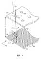
- FIG. 4is a perspective view of a portion of the pinhole imaging plate and planar array of light-sensitive cells comprising the wavefront sensor from the embodiment of FIG. 3 where the deflection of a wavefront piece associated with an aberrated eye is shown in comparison with a wavefront piece associated with a calibration or planar wavefront;
- FIG. 5is a plan view of a designated area on the planar array of light-sensitive cells associated with a corresponding hole;
- FIG. 6is a schematic of another embodiment of a wavefront analyzer used in the present invention.
- FIG. 7is a schematic view of an embodiment of the present invention suitable for ophthalmic use.
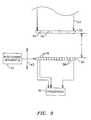
- FIG. 8is a side view of a cornea showing a thickness of corneal material to be ablated as an optical correction generated by the present invention.
- the present inventionwill be described with respect to diagnosing and correcting a human eye.
- teachings of the present inventionare applicable to any optical system having a real image focus that can (or can be adapted to) diffusely reflect a focused spot of radiation from a rear portion of the optical system back through the optical system as a wavefront of radiation.
- the present inventioncan be used with human or animal eyes of patients that may be alive or dead, or any man-made optical system satisfying the criteria regarding the real image focus.
- Distorted wavefront 130can be described mathematically as W(x,y).
- One method of measuring the distortions in wavefront 130is to determine the spatial separation ⁇ z between a reference plane 131 (analogous to ideal wavefront 110 ) at a known distance z O from the eye at each (x,y) point of distorted wavefront 130 as the leading edge of wavefront 130 traverses distance z O . This is illustrated in FIG. 1 C and is described mathematically as
- the appropriate correctionconsists of removing these optical path differences. Ideally, such correction is performed at reference plane 131 .
- the amount of material removed or added at each (x,y) coordinatecan be calculated directly if the refractive index of the material in question is known.
- wavefront analysiscan be performed repetitively during the procedure to provide feedback information as to the appropriate endpoint of the procedure.
- the differences ⁇ z(x,y) between the distorted and ideal wavefrontsare the consequence of the aberrations in the eye.
- Ablationcould then be carried out discretely at each (x,y) coordinate along the cornea by a laser beam delivery and eye tracking system such as disclosed in U.S. patent application Ser. No. 08/232,615, filed Apr. 25, 1994, owned by the same assignee as the present invention, and which is incorporated herein by reference.
- the appropriate corneal ablation depth at any (x,y) transverse coordinateis, to within a small error, given by
- n cis the refractive index of corneal tissue or 1.3775.
- the method described in detail belowcalculates ⁇ z(x,y) by first measuring the local slopes in wavefront 130 , i.e., ⁇ W(x,y)/ ⁇ x and ⁇ W(x,y)/ ⁇ y, at a number of points in the transverse x and y directions in reference plane 131 and then generating a mathematical description of W(x,y) having slopes in best possible agreement with the experimentally determined values.
- ⁇ W(x O ,y O )/ ⁇ xis referenced in FIG. 1 D.
- the magnitude of error E x (x,y)can be found for each measurement location (x,y) measured at an arbitrary coordinate, e.g., (x O ,y O ) by projecting that location back to the point of origin on cornea 126 .
- Thiscan be explained mathematically using FIG. 1 D.
- L ⁇ ( x )z 0 - ( x - x 0 ) ⁇ ⁇ ⁇ W ⁇ ( x 0 , y 0 ) / ⁇ ⁇ ⁇ x ( 3 )
- the transverse errorunder most circumstances will be negligible.
- the errorwill be zero at the origin where the corneal tissue and reference plane 131 are tangent.
- the tissueis approximately spherical with a radius of curvature of approximately 7.5-8.0 mm.
- the corrective treatment radiusis typically no more than 3 mm, and local wavefront radius of curvature will almost always exceed 50 mm (a 20 diopter refractive error).
- the transverse error E at a 3 mm treatment radius for a local wavefront radius of curvature of 50 mmis less than 40 mm.
- wavefront analysiscan also be used repetitively during the corrective procedure to provide useful feedback information.
- One example of such usewould be in cataract surgery where wavefront analysis could be performed on the eye following placement of an intra-ocular lens implant (IOL). The analysis could help identify whether the appropriate refractive power IOL has been inserted, or whether a different refractive power IOL should be used.
- Another example of repetitive wavefront analysiswould be during keratoplastic procedures where the cornea of the eye is deliberately distorted by altering the mechanical tension around the periphery thereof.
- repetitive wavefront analysiscould be used to refine the degree of induced tension change at each point around the cornea thereby providing the tool to obtain, optimum surface curvature for best visual acuity.
- the amount of spatial separation of component portions of wavefront 130 relative to the corresponding component portions of a planar or ideal wavefrontmust be measured. It is the system and method of the present invention that allows such separation to be objectively and accurately measured for even substantially aberrated eyes including those exhibiting severe defects such as severe myopia or hyperopia.
- the patient's pupilshould ideally be dilated to approximately 6 millimeters or more, i.e., the typical size of a human pupil in low light.
- the eyeis evaluated while it is using the greatest area of the cornea so that any correction developed from such measurement takes into account the largest usable corneal area of the patient's eye.
- Dilationcan be brought about naturally by implementing the measurement portion of the present invention in a low light environment such as a dimly lit room. Dilation can also be induced through the use of pharmacologic agents.
- System 10includes laser 12 for generating the optical radiation used to produce a small-diameter laser beam.
- Laser 12is typically a laser generating collimated laser light (represented by dashed lines 14 ) of a wavelength and power that is eye-safe.
- appropriate wavelengthswould include the entire visible spectrum from approximately 400-710 nanometers and the near infrared spectrum from approximately 710-1000 nanometers. While operation in the visible spectrum is generally preferable (since these are the conditions in which the eye operates), the near infrared spectrum may offer advantages in certain applications.
- the patient's eyemay be more relaxed if the patient does not know measurement is taking place.
- powershould be restricted in ophthalmic applications to eyesafe levels.
- eyesafe exposure levelscan be found in the U.S. Federal Performance Standard for Laser Products. If the analysis is to be performed on an optical system other than the eye, the examination wavelength range logically should incorporate the intended performance range of the system.
- an iris diaphragm 16can be used to block all of laser light 14 except for laser beam 18 of a size desired for use by the present invention.
- laser beam 18can have a diameter in the range of approximately 0.5-4.5 millimeters with 1-3 millimeters being typical. A badly aberrated eye requires a smaller diameter beam while an eye with only slight aberrations can be evaluated with a larger diameter beam.
- a lens(not shown) can be positioned in the beam path to optimize collimation.
- Laser beam 18is a polarized beam that is passed through a polarization sensitive beam splitter 20 enroute to being directed to a focusing optical train 22 .
- Optical train 22operates to focus laser beam 18 through the optics of eye 120 (e.g., cornea 126 , pupil 125 and lens 124 ) to the back of the eye's retina 122 .
- lens 124may not be present for a patient that has undergone a cataract procedure, however, this does not affect the present invention.
- optical train 22images laser beam 18 as a small spot of light at or near the eye's fovea centralis 123 where the eye's vision is most acute.
- the small spot of lightcould be reflected off another portion of retina 122 in order to determine aberrations related to another aspect of one's vision. For example, if the spot of light were reflected off the area of retina 122 surrounding the fovea centralis 123 , aberrations specifically related to one's peripheral vision could be evaluated. In all cases, the spot of light is sized to form a near-diffraction limited image on retina 122 . Thus, the spot of light produced by laser beam 18 at fovea centralis 123 does not exceed approximately 100 micrometers in diameter and, typically, is on the order of 10 micrometers.
- the diffuse reflection of laser beam 18 back from retina 122is represented in FIG. 2 by solid lines 24 indicative of the wavefront of radiation that passes back through eye 120 .
- Wavefront 24impinges on and is passed through optical train 22 enroute to polarization sensitive beam splitter 20 .
- Wavefront 24is depolarized relative to laser beam 18 due to reflection and refraction as wavefront 24 comes off retina 122 . Accordingly, wavefront 24 is turned at polarization sensitive beam splitter 20 and directed to a wavefront analyzer 26 such as a Hartmann-Shack (H-S) wavefront analyzer.
- H-SHartmann-Shack
- wavefront analyzer 26measures the slopes of wavefront 24 , i.e., the partial derivatives with respect to x and y, at a number of (x,y) transverse coordinates. This partial derivative information is then used to reconstruct or approximate the original wavefront with a mathematical expression such as a weighted series of Zernike polynomials.
- stray radiationmay be sufficiently small when compared to the radiation returning from the desired target (e.g., retina 122 ) so that the above polarization specifications are unnecessary.
- the present inventionis able to adapt to a wide range of vision defects and as such achieves a new level of dynamic range in terms of measuring ocular aberrations.
- Dynamic range enhancementis accomplished with optical train 22 and/or the wavefront sensor portion of wavefront analyzer 26 as will now be explained.
- optical train 22includes a first lens 220 , a flat mirror 221 , a Porro mirror 222 and a second lens 224 all of which lie along the path of laser beam 18 and wavefront 24 .
- First lens 220 and second lens 224are identical lenses maintained in fixed positions.
- Porro mirror 222is capable of linear movement as indicated by arrow 223 to change the optical path length between lenses 220 and 224 .
- the present inventionis not limited to the particular arrangement of flat mirror 221 and Porro mirror 222 and that other optical arrangements could be used between lenses 220 and 224 to change the optical path length therebetween.
- the “zero position” of Porro mirror 222can be identified by replacing eye 120 in FIG. 2 by a broad beam source (not shown) of collimated light to simulate a perfect plane wave.
- a broad beam sourcecould be realized by a laser beam expanded by a beam telescope to the diameter that will cover the imaging plane of wavefront analyzer 26 and adjusting Porro mirror 222 until wavefront analyzer 26 detects the light as being collimated.
- the changes in optical path length brought about by Porro mirror 222can be calibrated in diopters to provide an approximate spherical dioptric correction as will be explained further below.
- the dynamic range of system 10can be further improved by utilizing a preferred embodiment wavefront analyzer to include an improved wavefront sensor arrangement.
- the wavefront analyzerincludes an opaque imaging plate 32 having an array of holes 34 passing therethrough, a planar array 36 of light-sensitive cells such as charge coupled device cells 38 , and a processor 40 coupled to planar array 36 of cells 38 .
- the combination of plate 32 and planar array 36comprises the unique wavefront sensor of this embodiment.
- Plate 32is maintained parallel to and spaced apart a separation distance F from planar array 36 . As will be explained further below, separation distance F can be varied to adjust the gain of the sensor.
- planar array 36is coupled to a positioning apparatus 42 , e.g., a conventional motorized linear positioner having precise movement capability, that can adjust the position of planar array 36 relative to plate 32 to change separation distance F as indicated by arrow 43 .
- a positioning apparatus 42e.g., a conventional motorized linear positioner having precise movement capability
- each of holes 34is of equal size and shape with a circle being typical owing to its ease of manufacture.
- a square array geometryis used for array of holes 34 although other array geometries can be used.
- each such wavefront piece 25passes through hole 34 to illuminate planar array 36 .
- the resulting image formed by each such wavefront piece 25is a positive shadow of the respective hole 34 .
- diffractiondoes occur in a way determined by the diameter D of each hole 34 , the wavelength A of the light source (i.e., wavefront 24 ) and the separation distance F between plate 32 and planar array 36 .
- the value Fis varied by positioning apparatus 42 to adjust the gain based on the particular patient as will be explained further below.
- plate 32 with holes 34could also be accomplished using a solid plate or film made from a light-sensitive material such as a photolithographic film.
- the array of holes 34would be replaced by an array of shaped light transmissive apertures through which light passes when impinging thereon. The remainder of such a plate or film would be impervious to light.
- the advantage achieved by such an embodimentis that the light transmissive apertures could easily be made to conform to any desired shape.
- each wavefront piece 25measures the amount of angular deflection of each wavefront piece 25 relative to a wavefront piece that would result from a planar wavefront. This is best seen in FIG. 4 where the calibration or planar wavefront of light results in a wavefront piece represented by arrow 112 (normal to plate 32 ) that illuminates a geometric spot 114 on planar array 36 .
- wavefront 24represents a distorted wavefront as described above
- wavefront piece 25will exhibit an amount of angular deflection relative to (calibrating) wavefront piece 112 .
- the angular deflectioncauses wavefront piece 25 to illuminate a geometric spot 27 on planar array 36 that is offset from (calibrating) spot 114 .
- the amount of offsetis measured relative to the centroids 116 and 29 of spots 114 and 27 , respectively.
- centroid 29is (typically) deflected in both the x and y directions of array 36 .
- the angular deflection in each of the x and y directionsis given by ⁇ x/F and ⁇ y/F, respectively.
- lenses 220 and 224are identical as mentioned above. However, in certain applications it may be desirable to magnify or minify the wavefront at the wavefront sensor. This can be accomplished by using lenses 220 and 224 of different focal lengths and adjusting the apparatus dimensions accordingly.
- the object plane of the apparatusshould ideally be tangent to the corneal surface which can be achieved by a variety of means. Thus, each point at the object plane of optical train 22 very nearly corresponds to the same point on the cornea (although since the cornea is curved, there will be a slight lateral displacement).
- Plate 32 (or the imaging plane of any wavefront sensor portion) of wavefront analyzer 26is positioned at the focal plane of lens 220 .
- the object planeis always imaged on plate 32 in direct correspondence with the wavefront image emerging from cornea 126 . This will be true regardless of the optical path length between lenses 220 and 224 .
- This structurethere are several advantages to this structure, one of which is that there are very good planar arrays of light-sensitive cells that are commercially available to image an area corresponding to the 6 millimeter central circular region of the cornea. Additional advantages will now be explained.
- plate 32(or the imaging plane of any wavefront sensor portion of wavefront analyzer 26 ) is to break wavefront 24 into wavefront pieces that can each be measured independently (in terms of propagation direction) at planar array 36 . Since in the preferred embodiment optical train 22 does not magnify or reduce the image in the object plane, a point at the object plane corresponds to the same point at the image plane of optical train 22 . With Porro mirror 222 set at its “zero position,” the direction each piece of wavefront 24 is traveling at the object plane is reproduced exactly at the image plane of wavefront analyzer 26 .
- the wavefront piece at the same location in the image planewill also be traveling away from the optical axis at an angle of 20°.
- the first wayis to utilize a wavefront sensor with sufficiently small light-sensitive cells 38 and sufficiently large holes 34 (or any other transmissive aperture). In this way, measurement of each wavefront piece can be performed to an acceptable accuracy using a small value for F.
- the second wayis to move planar array 36 along the optical axis to change the separation distance F to plate 32 .
- planar array 36is positioned close to plate 32 to keep the projected wavefront pieces well separated and on planar array 36 .
- planar array 36can be moved to increase the separation distance F to plate 32 to make a more accurate measurement.
- the advantage of moving planar array 36 to change the separation distance F to plate 32is that the wavefront analysis is easily achieved for any position.
- the third way of compensating for severe aberrations in the present inventionis to change the optical path length between lenses 220 and 224 .
- Moving Porro mirror 222will not affect where the wavefront hits plate 32 , but will change the angular deflections at which the projected wavefront pieces pass through plate 32 , i.e., ⁇ x/F and ⁇ y/F. Decreasing the optical path length between lenses 220 and 224 will tend to pull the wavefront pieces toward the center of planar array 36 thereby compensating for hyperopia.
- the degree to which the angular deflection associated with each wavefront piece is alteredis a linear function of its distance off the optical axis and the movement of Porro mirror 222 from its zero position.
- each spotIn order to accurately determine the centroids of a spot of light impinging on array 36 , it is necessary to provide a fine structure of cells 38 relative to a spot size. In other words, each spot must cover a plurality of cells 38 .
- a unique number of cells 38is assigned to each hole 34 .
- the “assigned areas”are designated in FIG. 5 by the heavy grid lines 39 . It is to be understood that grid lines 39 are not actual physical boundaries between cells 38 but are shown simply to illustrate the unique designated areas containing a plurality of cells 38 .
- Other centroid strategiescan be utilized that do not necessitate such partitioning of array 36 .
- the wavefront sensor of the present inventiondoes not focus each wavefront piece to a minimum at the surface of array 36 , a larger plurality of cells 38 are illuminated by each geometric spot so that the centroid of each spot can be determined to a greater precision than was previously possible.
- the present inventioncould also be practiced with a wavefront analyzer that replaced plate 32 (FIG. 3) with a two-dimensional array of identical spherical lenslets 33 as shown in FIG. 6 .
- array 33is positioned by positioning apparatus 42 such that separation distance F is independent of the focal length f that defines the focal plane of array 33 which is represented by dashed line 35 .
- each wavefront piecee.g., wavefront piece 37
- each wavefront piecepassed through a subaperture of array 33 is reduced in size (e.g., diameter) but is not necessarily brought to a minimum focus at array 36 as it would be if separation distance F were equal to focal length f.
- array 33is positioned to concentrate the light in each wavefront piece over an area for sufficient intensity on planar array 36 , yet still illuminate a substantial plurality of cells 38 (as described above) for greatest accuracy in determining the deflection of the spot's centroid.
- processor 40computes each two-dimensional centroid of each spot generated by a wavefront 24 .
- the amount of two-dimensional centroid shift (relative to the centroid of the calibrating spot) for each designated area associated with a corresponding hole 34 (or subaperture of array 33 )is divided by the separation distance F to generate a matrix of local slopes of the wavefront, i.e., ⁇ W(x,y)/ ⁇ x and ⁇ W(x,y)/ ⁇ y at the (x,y), coordinates of the centers of holes 34 .
- ⁇ W(x,y)/ ⁇ x and ⁇ W(x,y)/ ⁇ y at the (x,y)coordinates of the centers of holes 34 .
- C iare the weighting coefficients
- Z i (x,y)are the Zernike polynomials up to some order.
- the upper limit n on the summationis a function of the number of Zernike polynomials, i.e., the highest order, used to approximate the true wavefront. If m is the highest order used, then
- n( m+ 1)( m+ 2)/2 (5)
- centroid of a spotThe directions of the unit normals at the center of each hole 34 are based on the centroids of the spots on cells 38 . Since each spot will illuminate a plurality of cells with varying intensity, a standard amplitude-weighted centroid calculation can be used to find the center of each spot. Each centroid must be measured twice, once for perpendicular collimated light, and again for the wavefront to be analyzed. Of course, all spots are imaged simultaneously during each exposure.
- system 10can be augmented by the addition of an eye tracker 25 .
- eye tracker 25One possible placement of eye tracker 25 is shown in FIG. 2 . However, it is to be understood that eye tracker 25 could be placed elsewhere in system 10 .
- One such eye trackeris disclosed in the aforementioned U.S. patent application Ser. No. 08/232,615. In this way, wavefront analysis could be performed even during a limited amount of eye motion.
- a one-time calibration exposurecan also be used to determine the relative sensitivities of the individual cells. This is made in uniform collimated light with plate 32 removed. The responses of individual cells are then recorded.
- the centroid in the collimated caseserves as a dedicated origin for the particular hole.
- the shift from the “origin” for each hole to the centroid caused by wavefront 24 (as observed in this coordinate system)is determined by the direction of the wave surface corresponding to that hole. If ⁇ x(m,n) is the x-component of the (m,n)th centroid and F is the plate separation, then the P-value for the (m,n)th centroid is
- each P(m,n) and Q(m,n)represents the partial derivatives of W(x,y) with respect to x and y for the (x,y) coordinates of each hole 34 .
- each hole 34is assigned its dedicated area of the array 36 or (i m,n ⁇ i, j m,n ⁇ j). This square of many light-sensitive cells is large enough that neighboring hole images never encroach, and all illumination from this hole is contained. The square contains 4 ⁇ i* ⁇ j cells.
- x cr ( i,j )x cw ( i,j ) ⁇ x c0 ( i,j ) (12)
- the surface partial derivatives P(i,j) and Q(i,j) for the array of hole centers of plate 32are next used to calculate the appropriate Zernike polynomial weighting coefficients to describe the original wavefront W(x,y). This will now be explained by way of illustration for a 7 ⁇ 7 square array of holes 34 . However, it is to be understood that other sizes and shapes of hole arrays could be used.
- the matrix PQis multiplied from the left with a transition matrix TM to get the matrix C as follows
- TMis a 98 wide by 14 high matrix and C is a 1 wide by 14 high matrix or column vector.
- TMis calculated for a given aperture, e.g., a 6 millimeter pupil aperture.
- the functions Z k (x,y) in equation (19)are the Zernike polynomials. There is no standard convention as to their sequence. Thus, for consistency, it is important that the same sequence is used to produce the set C k that was chosen for deriving the matrix TM. They occur in groups of the same order, which is the highest exponent in the group, with the total number of members in an order increasing with the order. For example, in a fourth order analysis, orders up to and including 4 are used (less Z 0 —the single member of order 0 that is the constant 1 which describes the reference position of the group in the z direction). Since wavefront 24 is moving along z (at the velocity of light), this “piston term” describes only an arbitrary offset in Z, and this term may be ignored. The first 5 orders (0, 1, . . . ,4) contain 15 functions including the piston term.
- 14 values of C kare calculated as coefficients of 14 Zernike polynomials.
- TMone such order used to calculate TM is given in Table 1, which includes both the Zernike functions and their partial derivatives.
- Calculation of the ⁇ z(x,y) optical path difference information from the Zernike reconstruction of the wavefrontis accomplished simply by subtracting a constant from the Zernike approximation.
- the value of the constantwill depend on the desired characteristics of ⁇ z(x,y).
- transition matrix TMThe development of the transition matrix TM will now be explained for the illustrated example of a 7 ⁇ 7 array of holes in plate 32 .
- the tangents of the components of the normalare P(x i ,y j ) and Q(x i ,y j ) where
- equation (25)gives the normal components in terms of the Zernike coefficients for a surface described by the array of 14 C's. These are exact, but it is not guaranteed that the actual total surface can be described by such an array of coefficients. Accordingly, if it is assumed that the description is within an acceptable tolerance, i.e., tolerating the errors that remain after least square error determination, then equation (26) can be considered to define the column vector C implicitly in terms of the mathematical matrix M and the measured vector PQ, both of which are known.
- the method of effecting the solution under the minimization conditionis as follows.
- equation (25)is multiplied on the left by M T , the transpose of M such that
- planar array 36To evaluate the eye unambiguously, all spots illuminating planar array 36 due to a wavefront 24 must be incident on planar array 36 simultaneously. This is achieved by pulsing or shuttering the laser source (i.e., laser 12 ) such that pulse duration is less than the saccadic motion interval of the eye, i.e., a few milliseconds.
- the laser sourcecould be left on continuously and wavefront 24 could be shuttered to appear as a wavefront pulse of a duration that is less than saccadic motion of the eye.
- shutter 50could be positioned in the path of laser beam 18 before eye 120 or in the path of wavefront 24 before wavefront analyzer 26 .
- FIG. 7An implementation of the present invention suitable for clinical use is shown schematically in FIG. 7 and is referenced generally by numeral 11 .
- Like reference numeralsare used to describe elements that are the same as those described above with respect to system 10 . Accordingly, the like elements and their functions will not be described further.
- a dichroic beam splitter 52is interposed between beam splitter 20 and optical train 22 to introduce fixation target optics 60 and observation optics 70 into system 11 which are optically separated from one another by 50/50 beam splitter 54 .
- fixation target opticsprovide eye 120 with visible light in the shape of a target.
- the visible light generated by fixation target optics 60is reflected by dichroic beam splitter 50 and directed through optical train 22 .
- fixation target optics 60can be implemented in a variety of fashions.
- one such embodimentis shown and includes visible light source 61 , light diffuser 62 , target 63 , field stop 64 , lens 65 and iris 66 .
- Light source 61 and light diffuser 62are used to provide uniform illumination of fixation target 63 .
- Field stop 64 , lens 65 , and iris 66are used in conjunction with optical train 22 to present a clear image of the fixation target to (patient) eye 120 .
- observation optics 70allows a technician to view and document the eye evaluation procedure. While a variety of implementations of observation optics 70 are possible, one such implementation is shown by way of example.
- observation optics 70includes field lens 71 , lens 72 , iris 73 , lens 74 , and camera 75 .
- a ring illuminator 80is placed in front of eye 120 to illuminate same for observation and/or filming purposes.
- the output from wavefront analyzer 26can be used in a variety of ways.
- the outputcould be used to continually or periodically monitor the progress or effects of an ophthalmic procedure.
- the outputcould also be used to develop an optical correction for eye 120 .
- the optical correctionwill make wavefront 24 appear approximately as a plane wave.
- the optical correctioncan be implemented in a variety of ways.
- the output of wavefront analyzer 26is input to a processor 90 which converts the Zernike expansion of equation (19) into a form suitable for being implemented as one of the possible optical corrections. (The functions of processor 90 could also be implemented at processor 40 of wavefront analyzer 26 .)
- Processor 90could use some of the Zernike coefficients from the expansion of equation (19) to generate a standard sphero-cylindrical correction for lens grinder 92 to produce a conventional optical lens, e.g., a lens for glasses, a contact lens, etc.
- Processor 90could also divide the Zernike reconstruction of the aberrated wavefront by the index of refraction of cornea 126 minus 1, to calculate the amount of corneal material to be ablated at each corresponding (x,y) location on the cornea.
- the amount of corneal material at each locationis input to a laser beam delivery system that typically has eye tracking capability 94 such as described in the afore-mentioned U.S. patent application Ser. No. 08/232,615.
- Laser beam delivery and eye tracker 94is placed in line with the optical axis of system 11 .
- the eye tracker portion of this elementallows system 11 to respond unwanted eye motion.
- Laser beam delivery and eye tracker 94would typically focus short pulses or “shots” of ablating laser light at cornea 126 or eye 120 to remove the specified thickness t of material at each location. This is shown diagrammatically in FIG. 8 where the uncorrected surface of cornea 126 is referenced by numeral 126 A and the corrected surface of cornea 126 after ablation is referenced by numeral 126 B.
- ablation thickness tis specified across the aperture of the cornea measured, e.g., the 6 millimeter circle to which the eye's pupil was dilated during the measurement of the eye. Outside the prescribed treatment circle, a tapering blend zone of partial ablation may be added to minimize severe changes in corneal curvature and hence lessen regression.
- Laser beam delivery system 94removes thickness t to achieve the optical correction, i.e., corrected cornea surface 126 B. Note that the optical correction is not concerned with the ultimate corneal topography, but instead removes corneal material to achieve an optical correction that takes into account all ocular aberrations of the eye.
- the present inventioncan be used to provide corneal surface corrections other than the conventional spherical and/or cylindrical corrections.
- the advantages of the present inventionare numerous. A totally objective approach is presented for measuring ocular aberrations. The approach is effective for a wide range of vision defects. Accordingly, the present invention will be of great utility in a wide variety of clinical applications.
- the calculated Zernike coefficientscan be used to develop a completely objective lens prescription or a corneal correction that could be accomplished with laser ablation.
- each of the wavefront sensor embodimentsprovides for a greater degree of accuracy over the prior art with respect to measuring wavefront deflections. Further, the present wavefront sensor can be adjusted in terms of gain simply by adjusting the separation distance between the imaging plane of the sensor and the planar array of light-sensitive cells.
- the objective measurement of the present inventionwill also find great utility for a large variety of applications in which the “patient” is unable to provide feedback as required by conventional eye diagnosis.
- the present inventioncould be used to evaluate the eyes of any patient not possessed of demonstrative communicative skills, e.g., babies, animals, dead specimens, as well as any constructed optical system, since the present invention is an objective analysis not requiring any assessment from the “subject.” All that is necessary is for the subject's eye to be properly positioned so that proper optical access to the eye can be obtained.
- the present inventioncould also be used in the area of identification should it be determined that each eye's Zernike coefficients are unique. Then, the present invention would find great utility in the fields of law enforcement, credit card/bank security, or any other field where positive identification would be beneficial.
Landscapes
- Health & Medical Sciences (AREA)
- Life Sciences & Earth Sciences (AREA)
- Ophthalmology & Optometry (AREA)
- General Health & Medical Sciences (AREA)
- Surgery (AREA)
- Engineering & Computer Science (AREA)
- Biomedical Technology (AREA)
- Heart & Thoracic Surgery (AREA)
- Veterinary Medicine (AREA)
- Public Health (AREA)
- Physics & Mathematics (AREA)
- Animal Behavior & Ethology (AREA)
- Biophysics (AREA)
- Molecular Biology (AREA)
- Medical Informatics (AREA)
- Optics & Photonics (AREA)
- Nuclear Medicine, Radiotherapy & Molecular Imaging (AREA)
- Vascular Medicine (AREA)
- Eye Examination Apparatus (AREA)
Abstract
Description
This application is a continuation of and incorporates by reference application Ser. No. 09/496,368 now abandoned, filed Feb. 2, 2000, which itself is a continuation of abandoned application Ser. No. 08/756,272, filed Nov. 25,1996, all commonly owned with the present application.
The invention relates generally to optical aberration measurement and correction, and more particularly to the objective measurement and correction of optical systems having a real image focus such as human and animal eyes.
Optical systems having a real image focus can receive collimated light and focus it at a point. Such optical systems can be found in nature, e.g., human and animal eyes, or can be man-made, e.g., laboratory systems, guidance systems, etc. In either case, aberrations in the optical system can affect the system's performance. By way of example, the human eye will be used to explain this problem.
Referring to FIG. 1A, a perfect orideal eye 100 is shown diffusely reflecting an impinging light beam (not shown for sake of clarity) from the back of its retina102 (i.e., the fovea centralis103) through the eye's optics to includelens 104 andcornea 106. For such an ideal eye in a relaxed state, i.e., not accommodating to provide near-field focus, the reflected light (represented by arrows108)exits eye 100 as a sequence as of plane waves, one of which is represented bystraight line 110. However, an eye normally has aberrations that cause deformation or distortion of the wave exiting the eye. This is shown by way of example in FIG. 1B whereaberrated eye 120 diffusely reflects an impinging light beam (again not shown for sake of clarity) from the back of itsretina 122 of thefovea centralis 123 throughlens 124 andcornea 126. Foraberrated eye 120, reflectedlight 128exits eye 120 as a sequence of distorted wavefronts, one of which is represented bywavy line 130.
Currently, there are a number of technologies that attempt to provide the patient with improved visual acuity. Examples of such technologies include remodeling ofcornea 126 using refractive laser surgery or intra-corneal implants, and adding synthetic lenses to the optical system using intraocular lens implants or precision-ground spectacles. In each case, the amount of corrective treatment is typically determined by placing spherical and/or cylindrical lenses of known refractive power at the spectacle plane (approximately 1.0-1.5 centimeters anterior to cornea126) and asking the patient which lens or lens combination provides the clearest vision. This is obviously a very imprecise measurement of the true distortions inwavefront 130 because 1) a single spherocylindrical compensation is applied across the entire wavefront, 2) vision is tested at discrete intervals (i.e., diopter units) of refractive correction, and 3) subjective determination by the patient is required in order to determine the optical correction. Thus, the conventional methodology for determining refractive errors in the eye is substantially less accurate than the techniques now available for correcting the ocular aberrations.
One method of measuring ocular refractive errors is disclosed by Penney et al. in “Spatially Resolved Objective Autorefractometer,” U.S. Pat. No. 5,258,791, issued Nov. 2, 1993. Penney et al. teach the use of an autorefractometer to measure the refraction of the eye at numerous discrete locations across the corneal surface. The autorefractometer is designed to deliver a narrow beam of optical radiation to the surface of the eye, and to determine where that beam strikes the retina using a retinal imaging system. Both the angle of the beam's propagation direction with respect to the optical axis of the system and the approximate location at which the beam strikes the corneal surface of the eye are independently adjustable. A small uncertainty or error in the location of the beam's point of incidence on the cornea exists due to the curved corneal surface. For each point of incidence across the corneal surface, the refraction of the eye corresponding to that surface point can be determined by adjusting the angle at which the beam strikes the cornea until the beam refracted on to the iris strikes the fovea centralis. Adjustment of the beam angle of propagation can be accomplished either manually by the patient or automatically by the autorefractometer if a feedback loop involving a retinal imaging component is incorporated.
Penney et al. further teach the use of the autorefractometer measurements in determining the appropriate corneal surface reshaping to provide emmetropia. This is accomplished by first obtaining accurate measurement of corneal surface topography (using a separate commercially available device). A mathematical analysis is then performed using the initial corneal topography at each surface reference point, the measured refraction at each surface point, and Snell's law of refraction, to determine the required change in surface contour at each reference point. The contour changes at the various reference points are then combined to arrive at a single reshaping profile to be applied across the full corneal surface.
The major limitation to the approach described by Penney et al. is that a separate measurement of corneal topography is required to perform the Snell's Law analysis of needed refraction change. This requirement adds significantly to the time and cost of the complete diagnostic evaluation. Furthermore, the accuracy of the refraction change analysis will be dependent on the accuracy of the topographic measurement and the accuracy of the autorefractometer measurement. In addition, any error in the spatial orientation of the topography “map” with respect to the refraction map will degrade the accuracy of the needed correction profile.
A second limitation to the approach described by Penney et al. is that test points on the corneal surface are examined sequentially. Eye motion during the examination, either voluntary or involuntary, could introduce substantial errors in the refraction measurement. Penney et al. attempt to provide detection of such eye movement by deliberately including measurement points outside the pupil, i.e., in the corneal region overlying the iris, where the return from the retina will obviously be zero at specific intervals in the examination sequence. However, this approach may still allow substantial undetected eye movement error between such iris reference points.
At present, no corrective method is based on the concurrent examination of the complete distortions inwavefront 130. Measurement of wave aberrations of the human eye, i.e., ocular aberrations, has been studied for a number of years. One prior art method and system are disclosed by Liang et al. in “Objective Measurement of Wave Aberrations of the Human Eye With the Use of a Hartmann-Shack Wave-front Sensor,” Journal of the Optical Society of America,Volume 11, No. 7, July 1994, p.p. 1949-1957. Liang et al. teach the use of a Hartmann-Shack wavefront sensor to measure ocular aberrations by measuring the wavefront emerging from the eye by the retinal reflection of a focused laser light spot on the retina's fovea. The actual wavefront is reconstructed using wavefront estimation with Zernike polynomials.
The Hartmann-Shack wavefront sensor disclosed by Liang et al. includes two identical layers of cylindrical lenses with the layers arranged so that the lenses in each layer are perpendicular to one another. In this way, the two layers act like a two-dimensional array of spherical lenslets that divide the incoming light wave into subapertures. The light through each subaperture is brought to focus in the focal plane of the lens array where a charge coupled device (CCD) image module resides.
The system of Liang et al. is calibrated by impinging an ideal plane wave of light on the lenslet array so that a reference or calibrating pattern of focus spots is imaged on the CCD. Since the ideal wavefront is planar, each spot related to the ideal wavefront is located on the optical axis of the corresponding lenslet. When a distorted wavefront passes through the lenslet array, the image spots on the CCD are shifted with respect to the reference pattern generated by the ideal wavefront. Each shift is proportional to the local slopes, i.e., partial derivatives, of the distorted wavefront which can be used to reconstruct the distorted wavefront, by means of modal wavefront estimation with Zernike polynomials.
However, the system disclosed by Liang et al. is effective only for eyes having fairly good vision. Eyes that exhibit considerable myopia (near-sightedness) would cause the focus spots to overlap on the CCD thereby making local slope determination impossible for eyes having this condition. Similarly, eyes that exhibit considerable hyperopia (farsightedness) deflect the focus spots such that they do not impinge on the CCD thereby again making local slope determination impossible for eyes having this condition.
Another limitation of the system of Liang et al. is the configuration of the Hartmann-Shack sensor in that the lenses must be uniform in order to define a uniform lenslet array so that the entire array shares a common focal plane and does not itself induce distortions in the wavefront. However, the manufacturing costs associated with such constraints are considerable.
Thus, owing to all of the above-noted limitations, Liang et al. can only achieve wavefront measurement for a relatively small class of patients. Such patients can have, at most, mildly distorted vision.
It is an object of the present invention to provide a method and system for objectively measuring aberrations of optical systems by wavefront analysis and for using such measurement to generate an optical correction.
Another object of the present invention is to provide for the objective measurement of ocular aberrations having a dynamic range that can cope with large amounts of such aberrations so as to be useful in practical applications.
Still another object of the present invention to provide a method and system for objectively measuring ocular aberrations using a wavefront analyzer of simple and inexpensive design.
It is further an object to correct vision by ablating corneal material using a laser beam directed to locations on the surface of the cornea of the eye in response to the objective measurements, thereby providing a measured wavefront that approximates a desired wavefront such as a plane wave.
Other objects and advantages of the present invention will become more obvious hereinafter in the specification and drawings.
To meet such objects, an optical correction system for correcting visual defects of an eye is provided which includes a wavefront analyzer disposed in the path of a wavefront emanating from the eye for determining an optical path difference between a plane wave and the wavefront, a converter for providing an optical correction based on the path difference and refractive indices of media through which the wavefront passes, and a laser beam having power sufficient for ablating corneal material of the cornea of the eye, wherein the optical correction is achieved by the removal of a selected amount of the corneal material.
A method aspect of the invention includes enhancing vision of an eye by optically correcting the eye based on an optical path difference between a plane wave and a wavefront emanating from the retina of the eye and refractive indices of media through which the wavefront passes, to thereby cause the wavefront to approximate the shape of the plane wave. Further, corneal surface altering is based on a Zernike reconstruction of the wavefront, and the optically correcting includes dividing the optical path difference by a difference between an index of refraction of corneal material and an index of refraction of air. The cornea is then ablated using a laser beam directed at selected locations on the surface of the cornea for altering the corneal surface of the eye without regard to a resulting topography of the surface of the cornea.
In accordance with the present invention, an energy source generates a beam of radiation. Optics, disposed in the path of the beam, direct the beam through a focusing optical system, e.g., an eye, that has a rear portion thereof functioning as a diffuse reflector. The beam is diffusely reflected back from the rear portion as a wavefront of radiation that passes through the focusing optical system to impinge on the optics. The optics project the wavefront to a wavefront analyzer in direct correspondence with the wavefront as it emerges from the focusing optical system. A wavefront analyzer is disposed in the path of the wavefront projected from the optics and calculates distortions of the wavefront as an estimate of ocular aberrations of the focusing optical system. The wavefront analyzer includes a wavefront sensor coupled to a processor that analyzes the sensor data to reconstruct the wavefront to include the distortions thereof.
In one embodiment, the radiation is optical radiation and the wavefront sensor is implemented using a plate and a planar array of light-sensitive cells. The plate is generally opaque but that has an array of light transmissive apertures that selectively let impinging light therethrough. The plate is disposed in the path of the wavefront so that portions of the wavefront pass through the light transmissive apertures. The planar array of cells is arranged parallel to and spaced apart from the plate by a selected distance. Each portion of the wavefront passing through one of the light transmissive apertures illuminates a geometric shape covering a unique plurality of cells. In another embodiment, the wavefront sensor comprises a two-dimensional array of spherical lenslets and a planar array of cells. The array of lenslets defines a focal plane that is a focal length away therefrom. The array of lenslets is disposed in the path of the wavefront where portions of the wavefront pass therethrough. The planar array of cells is arranged parallel to and spaced apart from the array of lenslets by a selected distance independent of the focal length. Similar to the first embodiment wavefront sensor, each portion of the wavefront illuminates a geometric shape covering a unique plurality of cells. Regardless of which wavefront sensor is used, the distance between the planar array of cells and the opaque plate, or the array of lenslets, can be varied to adjust the slope measurement gain of the wavefront sensor and thereby improve the dynamic range of the system.
Another measure of dynamic range enhancement is provided by the focusing optics. The focusing optics includes first and second lenses maintained in fixed positions in the path of the beam and wavefront. An arrangement of optical elements is disposed between the lenses in the path of the beam and the wavefront. The optical elements are adjustable to change the optical path length between the lenses.
If an optical correction is desired, the distortions are converted to an optical correction which, if placed in the path of the wavefront, causes the wavefront to appear approximately as a plane wave. The optical correction can be in the form of a lens or an amount of corneal material ablated from the eye.
FIG. 1A is a schematic view of the ideal eye reflecting light from its retina as a planar wavefront;
FIG. 1B is a schematic view of an aberrated eye reflecting light from its retina as a deformed wavefront;
FIG. 1C is a schematic view of the distorted wavefront relative to a reference plane to show the wavefront error or optical path difference as a function of transverse distance in the propagation direction;
FIG. 1D is a schematic view of the distorted wavefront relative to a reference plane that is tangent to the surface of the cornea;
FIG. 2 is a simplified schematic of the system for determining ocular aberrations in accordance with the essential features of the present invention;
FIG. 3 is a schematic of one embodiment of a Hartmann Shack wavefront analyzer used in the present invention;
FIG. 4 is a perspective view of a portion of the pinhole imaging plate and planar array of light-sensitive cells comprising the wavefront sensor from the embodiment of FIG. 3 where the deflection of a wavefront piece associated with an aberrated eye is shown in comparison with a wavefront piece associated with a calibration or planar wavefront;
FIG. 5 is a plan view of a designated area on the planar array of light-sensitive cells associated with a corresponding hole;
FIG. 6 is a schematic of another embodiment of a wavefront analyzer used in the present invention;
FIG. 7 is a schematic view of an embodiment of the present invention suitable for ophthalmic use; and
FIG. 8 is a side view of a cornea showing a thickness of corneal material to be ablated as an optical correction generated by the present invention.
By way of illustrative example, the present invention will be described with respect to diagnosing and correcting a human eye. However, it is to be understood that the teachings of the present invention are applicable to any optical system having a real image focus that can (or can be adapted to) diffusely reflect a focused spot of radiation from a rear portion of the optical system back through the optical system as a wavefront of radiation. Thus, the present invention can be used with human or animal eyes of patients that may be alive or dead, or any man-made optical system satisfying the criteria regarding the real image focus.
The method of using wavefront analysis to determine an appropriate optical correction will be introduced with reference to the eye example and the aid of the schematic shown in FIG.1C. For convenience, a coordinate system is defined where positive x is upward in the plane of the figure, positive y is outward from the plane of the figure, and positive z is to the right along the propagation direction.Distorted wavefront 130 can be described mathematically as W(x,y).
One method of measuring the distortions inwavefront 130 is to determine the spatial separation Δz between a reference plane131 (analogous to ideal wavefront110) at a known distance zOfrom the eye at each (x,y) point ofdistorted wavefront 130 as the leading edge ofwavefront 130 traverses distance zO. This is illustrated in FIG.1C and is described mathematically as
These Δz measurements define the inappropriate optical path differences due to the aberrations in the test eye. The appropriate correction consists of removing these optical path differences. Ideally, such correction is performed atreference plane 131.
Depending on the corrective therapy (i.e., corneal tissue ablation, synthetic lens addition, etc.), the amount of material removed or added at each (x,y) coordinate can be calculated directly if the refractive index of the material in question is known. For many procedures, such as intra-ocular lens implantation or radial keratotomy, such wavefront analysis can be performed repetitively during the procedure to provide feedback information as to the appropriate endpoint of the procedure.
In terms of the illustrative example, the differences Δz(x,y) between the distorted and ideal wavefronts are the consequence of the aberrations in the eye. Ideal correction of those aberrations consists of introducing an optical path difference atreference plane 131 of negative Δz(x,y). If the treatment approach consists of removing tissue from the surface of the cornea by laser ablation, then a logical choice for the location ofreference plane 131 is tangential to the surface of cornea126 (i.e., zO=0). This is shown schematically in FIG. 1D where the curvature ofcornea 126 is greatly exaggerated for clarity of illustration. Ablation could then be carried out discretely at each (x,y) coordinate along the cornea by a laser beam delivery and eye tracking system such as disclosed in U.S. patent application Ser. No. 08/232,615, filed Apr. 25, 1994, owned by the same assignee as the present invention, and which is incorporated herein by reference.
The appropriate corneal ablation depth at any (x,y) transverse coordinate is, to within a small error, given by
where ncis the refractive index of corneal tissue or 1.3775. The method described in detail below calculates Δz(x,y) by first measuring the local slopes inwavefront 130, i.e., δW(x,y)/δx and δW(x,y)/δy, at a number of points in the transverse x and y directions inreference plane 131 and then generating a mathematical description of W(x,y) having slopes in best possible agreement with the experimentally determined values. One such slope δW(xO,yO)/δx is referenced in FIG.1D. In doing this, a small error is introduced due to the fact that distortedwavefront 130 is measured atreference plane 131 whilewavefront 130 emerged from a curved (corneal) surface just posterior to referenceplane 131. This error is similar to that encountered with the prior art method of Penney et al. discussed above. The error Ex(x,y) is the lateral displacement in the x-direction at each (x,y) location at the measurement plane (i.e., reference plane131) to the curved corneal surface. A similar error will be manifest for any corrections involving curved optical surfaces. The error will generally increase with both (x,y) displacement from the point of tangency and local wavefront error.
The magnitude of error Ex(x,y) can be found for each measurement location (x,y) measured at an arbitrary coordinate, e.g., (xO,yO) by projecting that location back to the point of origin oncornea 126. This can be explained mathematically using FIG.1D. For simplicity, the explanation will assume that the error is only in the plane of the figure, i.e., the plane defined by y=yO, although it is quite straightforward mathematically to extend the analysis to include errors the y-dimension. The quantation of the line L tracing the propagation of the wavefront element measured at (xO,yO) in the zOreference plane from the corneal surface to the reference plane is:

If the corneal surface in the plane of the figure is described by the expression S(xO,yO), then the point of origin for the wavefront element in question can be found by finding the point of intersection between L(x) and S(x,yO). Mathematically, this requires finding the value x′ that satisfies L (x′)=S(xO,yO). The error Ex(xO,yO) then is given as Ex(xO,yO)=x′−xO. Extending the analysis to consider errors in the y-direction would yield a similar expression for EYwhere EY(xO,yO)=y′−yO. If significant, these transverse errors can be compensated for by laterally displacing the aberration correction calculated at each (x,y) coordinate by the amounts EX(x,y) and EY(x,y)
In the case of human corneas, the transverse error under most circumstances will be negligible. The error will be zero at the origin where the corneal tissue andreference plane 131 are tangent. For human corneas, the tissue is approximately spherical with a radius of curvature of approximately 7.5-8.0 mm. The corrective treatment radius is typically no more than 3 mm, and local wavefront radius of curvature will almost always exceed 50 mm (a 20 diopter refractive error). The transverse error E at a 3 mm treatment radius for a local wavefront radius of curvature of 50 mm is less than 40 mm.
For certain ophthalmic procedures, wavefront analysis can also be used repetitively during the corrective procedure to provide useful feedback information. One example of such use would be in cataract surgery where wavefront analysis could be performed on the eye following placement of an intra-ocular lens implant (IOL). The analysis could help identify whether the appropriate refractive power IOL has been inserted, or whether a different refractive power IOL should be used. Another example of repetitive wavefront analysis would be during keratoplastic procedures where the cornea of the eye is deliberately distorted by altering the mechanical tension around the periphery thereof. Here, repetitive wavefront analysis could be used to refine the degree of induced tension change at each point around the cornea thereby providing the tool to obtain, optimum surface curvature for best visual acuity.
In order to perform wavefront analysis in a manner compatible with corrective procedures such as those described above, the amount of spatial separation of component portions ofwavefront 130 relative to the corresponding component portions of a planar or ideal wavefront must be measured. It is the system and method of the present invention that allows such separation to be objectively and accurately measured for even substantially aberrated eyes including those exhibiting severe defects such as severe myopia or hyperopia.
For the evaluation or measurement portion of the present invention, the patient's pupil should ideally be dilated to approximately 6 millimeters or more, i.e., the typical size of a human pupil in low light. In this way, the eye is evaluated while it is using the greatest area of the cornea so that any correction developed from such measurement takes into account the largest usable corneal area of the patient's eye. (A lesser amount of the cornea is used in daylight where the pupil is considerable smaller, e.g., on the order of 3 millimeters.) Dilation can be brought about naturally by implementing the measurement portion of the present invention in a low light environment such as a dimly lit room. Dilation can also be induced through the use of pharmacologic agents.
Referring now to FIG. 2, a simplified schematic of the system of the present invention depicting its essential elements is shown and referenced generally bynumeral 10.System 10 includeslaser 12 for generating the optical radiation used to produce a small-diameter laser beam.Laser 12 is typically a laser generating collimated laser light (represented by dashed lines14) of a wavelength and power that is eye-safe. For ophthalmic applications, appropriate wavelengths would include the entire visible spectrum from approximately 400-710 nanometers and the near infrared spectrum from approximately 710-1000 nanometers. While operation in the visible spectrum is generally preferable (since these are the conditions in which the eye operates), the near infrared spectrum may offer advantages in certain applications. For example, the patient's eye may be more relaxed if the patient does not know measurement is taking place. Regardless of the wavelength of the optical radiation, power should be restricted in ophthalmic applications to eyesafe levels. For laser radiation, appropriate eye-safe exposure levels can be found in the U.S. Federal Performance Standard for Laser Products. If the analysis is to be performed on an optical system other than the eye, the examination wavelength range logically should incorporate the intended performance range of the system.
To select a small-diameter collimated core oflaser light 14, aniris diaphragm 16 can be used to block all oflaser light 14 except forlaser beam 18 of a size desired for use by the present invention. In terms of the present invention,laser beam 18 can have a diameter in the range of approximately 0.5-4.5 millimeters with 1-3 millimeters being typical. A badly aberrated eye requires a smaller diameter beam while an eye with only slight aberrations can be evaluated with a larger diameter beam. Depending on the output divergence oflaser 12, a lens (not shown) can be positioned in the beam path to optimize collimation.
The diffuse reflection oflaser beam 18 back fromretina 122 is represented in FIG. 2 bysolid lines 24 indicative of the wavefront of radiation that passes back througheye 120.Wavefront 24 impinges on and is passed throughoptical train 22 enroute to polarizationsensitive beam splitter 20.Wavefront 24 is depolarized relative tolaser beam 18 due to reflection and refraction aswavefront 24 comes offretina 122. Accordingly,wavefront 24 is turned at polarizationsensitive beam splitter 20 and directed to awavefront analyzer 26 such as a Hartmann-Shack (H-S) wavefront analyzer. In general,wavefront analyzer 26 measures the slopes ofwavefront 24, i.e., the partial derivatives with respect to x and y, at a number of (x,y) transverse coordinates. This partial derivative information is then used to reconstruct or approximate the original wavefront with a mathematical expression such as a weighted series of Zernike polynomials.
The purpose of the above-specified polarizations states forincident laser beam 18 andbeamsplitter 20 is to minimize the amount of stray laser radiation reaching the sensor portion ofwavefront analyzer 26. In some situations, stray radiation may be sufficiently small when compared to the radiation returning from the desired target (e.g., retina122) so that the above polarization specifications are unnecessary.
The present invention is able to adapt to a wide range of vision defects and as such achieves a new level of dynamic range in terms of measuring ocular aberrations. Dynamic range enhancement is accomplished withoptical train 22 and/or the wavefront sensor portion ofwavefront analyzer 26 as will now be explained.
In the illustrated embodiment,optical train 22 includes afirst lens 220, aflat mirror 221, aPorro mirror 222 and asecond lens 224 all of which lie along the path oflaser beam 18 andwavefront 24.First lens 220 andsecond lens 224 are identical lenses maintained in fixed positions.Porro mirror 222 is capable of linear movement as indicated byarrow 223 to change the optical path length betweenlenses flat mirror 221 andPorro mirror 222 and that other optical arrangements could be used betweenlenses
The “zero position” ofPorro mirror 222 can be identified by replacingeye 120 in FIG. 2 by a broad beam source (not shown) of collimated light to simulate a perfect plane wave. Such a source could be realized by a laser beam expanded by a beam telescope to the diameter that will cover the imaging plane ofwavefront analyzer 26 and adjustingPorro mirror 222 untilwavefront analyzer 26 detects the light as being collimated. Note that the changes in optical path length brought about byPorro mirror 222 can be calibrated in diopters to provide an approximate spherical dioptric correction as will be explained further below.
The dynamic range ofsystem 10 can be further improved by utilizing a preferred embodiment wavefront analyzer to include an improved wavefront sensor arrangement. One such wavefront sensor arrangement will now be explained with the aid of FIGS. 3 and 4. In FIG. 3, the wavefront analyzer includes anopaque imaging plate 32 having an array ofholes 34 passing therethrough, aplanar array 36 of light-sensitive cells such as charge coupleddevice cells 38, and aprocessor 40 coupled toplanar array 36 ofcells 38. The combination ofplate 32 andplanar array 36 comprises the unique wavefront sensor of this embodiment.Plate 32 is maintained parallel to and spaced apart a separation distance F fromplanar array 36. As will be explained further below, separation distance F can be varied to adjust the gain of the sensor. To do this,planar array 36 is coupled to apositioning apparatus 42, e.g., a conventional motorized linear positioner having precise movement capability, that can adjust the position ofplanar array 36 relative to plate32 to change separation distance F as indicated byarrow 43. With respect to the array ofholes 34, each ofholes 34 is of equal size and shape with a circle being typical owing to its ease of manufacture. In the illustrated example, a square array geometry is used for array ofholes 34 although other array geometries can be used.
As shown in FIG. 4, whenwavefront 24 impinges onplate 32, a piece or portion ofwavefront 24, indicated byarrow 25, passes throughhole 34 to illuminateplanar array 36. To a first order, the resulting image formed by eachsuch wavefront piece 25 is a positive shadow of therespective hole 34. However, diffraction does occur in a way determined by the diameter D of eachhole 34, the wavelength A of the light source (i.e., wavefront24) and the separation distance F betweenplate 32 andplanar array 36. The value F is varied by positioningapparatus 42 to adjust the gain based on the particular patient as will be explained further below.
Note that the function provided byplate 32 withholes 34 could also be accomplished using a solid plate or film made from a light-sensitive material such as a photolithographic film. In such a case, the array ofholes 34 would be replaced by an array of shaped light transmissive apertures through which light passes when impinging thereon. The remainder of such a plate or film would be impervious to light. The advantage achieved by such an embodiment is that the light transmissive apertures could easily be made to conform to any desired shape.
Regardless, of how eachwavefront piece 25 is generated, the present invention measures the amount of angular deflection of eachwavefront piece 25 relative to a wavefront piece that would result from a planar wavefront. This is best seen in FIG. 4 where the calibration or planar wavefront of light results in a wavefront piece represented by arrow112 (normal to plate32) that illuminates ageometric spot 114 onplanar array 36. In contrast, assumingwavefront 24 represents a distorted wavefront as described above,wavefront piece 25 will exhibit an amount of angular deflection relative to (calibrating)wavefront piece 112. The angular deflection causeswavefront piece 25 to illuminate ageometric spot 27 onplanar array 36 that is offset from (calibrating)spot 114. In terms of the present invention, the amount of offset is measured relative to thecentroids spots planar array 36,centroid 29 is (typically) deflected in both the x and y directions ofarray 36. Thus, the angular deflection in each of the x and y directions is given by Δx/F and Δy/F, respectively.
In the preferred embodiment,lenses lenses optical train 22 very nearly corresponds to the same point on the cornea (although since the cornea is curved, there will be a slight lateral displacement). Plate32 (or the imaging plane of any wavefront sensor portion) ofwavefront analyzer 26 is positioned at the focal plane oflens 220. In this way, the object plane is always imaged onplate 32 in direct correspondence with the wavefront image emerging fromcornea 126. This will be true regardless of the optical path length betweenlenses
The purpose of plate32 (or the imaging plane of any wavefront sensor portion of wavefront analyzer26) is to breakwavefront 24 into wavefront pieces that can each be measured independently (in terms of propagation direction) atplanar array 36. Since in the preferred embodimentoptical train 22 does not magnify or reduce the image in the object plane, a point at the object plane corresponds to the same point at the image plane ofoptical train 22. WithPorro mirror 222 set at its “zero position,” the direction each piece ofwavefront 24 is traveling at the object plane is reproduced exactly at the image plane ofwavefront analyzer 26. For example, if a wavefront piece at a location in the object plane was traveling away from the optical axis at an angle of 20° with respect to the optical axis that is perpendicular to the object plane, the wavefront piece at the same location in the image plane will also be traveling away from the optical axis at an angle of 20°.
Note that a person who is myopic will produce a wavefront such that the wavefront pieces isolated byplate 32 will converge toward the center ofplanar array 36. A hyperopic person will produce a wavefront such that the wavefront pieces isolated byplate 32 diverge. Thus, a person with a significant vision error becomes difficult to evaluate because wavefront pieces can either overlap (myopia) atplanar array 36 or spill off (hyperopia)planar array 36.
In the present invention, there are three ways of compensating for such severe aberrations. The first way is to utilize a wavefront sensor with sufficiently small light-sensitive cells 38 and sufficiently large holes34 (or any other transmissive aperture). In this way, measurement of each wavefront piece can be performed to an acceptable accuracy using a small value for F. The second way is to moveplanar array 36 along the optical axis to change the separation distance F to plate32. For a person with a severe aberration,planar array 36 is positioned close toplate 32 to keep the projected wavefront pieces well separated and onplanar array 36. For a mild aberration,planar array 36 can be moved to increase the separation distance F to plate32 to make a more accurate measurement. The advantage of movingplanar array 36 to change the separation distance F to plate32 is that the wavefront analysis is easily achieved for any position. The third way of compensating for severe aberrations in the present invention is to change the optical path length betweenlenses Porro mirror 222 will not affect where the wavefront hitsplate 32, but will change the angular deflections at which the projected wavefront pieces pass throughplate 32, i.e., Δx/F and Δy/F. Decreasing the optical path length betweenlenses planar array 36 thereby compensating for hyperopia. Increasing the optical path length betweenlenses planar array 36 thereby compensating for myopia. The degree to which the angular deflection associated with each wavefront piece is altered is a linear function of its distance off the optical axis and the movement of Porro mirror222 from its zero position.
In order to accurately determine the centroids of a spot of light impinging onarray 36, it is necessary to provide a fine structure ofcells 38 relative to a spot size. In other words, each spot must cover a plurality ofcells 38. In the preferred embodiment, to determine the centroid of each spot unambiguously with respect to a spot caused by another one ofholes 34, a unique number ofcells 38 is assigned to eachhole 34. The “assigned areas” are designated in FIG. 5 by the heavy grid lines39. It is to be understood that grid lines39 are not actual physical boundaries betweencells 38 but are shown simply to illustrate the unique designated areas containing a plurality ofcells 38. Other centroid strategies can be utilized that do not necessitate such partitioning ofarray 36.
Since the wavefront sensor of the present invention does not focus each wavefront piece to a minimum at the surface ofarray 36, a larger plurality ofcells 38 are illuminated by each geometric spot so that the centroid of each spot can be determined to a greater precision than was previously possible.
The present invention could also be practiced with a wavefront analyzer that replaced plate32 (FIG. 3) with a two-dimensional array of identicalspherical lenslets 33 as shown in FIG.6. To achieve the advantages of the present invention,array 33 is positioned by positioningapparatus 42 such that separation distance F is independent of the focal length f that defines the focal plane ofarray 33 which is represented by dashedline 35. In other words, each wavefront piece (e.g., wavefront piece37) passed through a subaperture ofarray 33 is reduced in size (e.g., diameter) but is not necessarily brought to a minimum focus atarray 36 as it would be if separation distance F were equal to focal length f. Thus, in practice,array 33 is positioned to concentrate the light in each wavefront piece over an area for sufficient intensity onplanar array 36, yet still illuminate a substantial plurality of cells38 (as described above) for greatest accuracy in determining the deflection of the spot's centroid.
Regardless of the structure of the wavefront sensor,processor 40 computes each two-dimensional centroid of each spot generated by awavefront 24. The amount of two-dimensional centroid shift (relative to the centroid of the calibrating spot) for each designated area associated with a corresponding hole34 (or subaperture of array33) is divided by the separation distance F to generate a matrix of local slopes of the wavefront, i.e., δW(x,y)/δx and δW(x,y)/δy at the (x,y), coordinates of the centers ofholes 34. For simplicity, these will be indicated by P(x,y)=δW(x,y)/δx and Q(x,y)=δW(x,y)/δy, respectively.
Numerous methods exist for using the partial derivative data to calculate the original (distorted) wavefront. One acceptable approach is that used by Liang et al. in the aforementioned paper where the wavefront is approximated using Zernike polynomials. This is a standard analytic technique described in numerous optics texts such as “Principles of Optics,” by M. Born and E. Wolf, Pergamon Press, Oxford, England, 1964. By way of example, the Zernike polynomial approach will be discussed herein. However, it is to be understood that other mathematical approaches can be used in approximating the distorted wavefront.

where Ciare the weighting coefficients, and Zi(x,y) are the Zernike polynomials up to some order. The upper limit n on the summation is a function of the number of Zernike polynomials, i.e., the highest order, used to approximate the true wavefront. If m is the highest order used, then
Derivation of the Zernike polynomials up to an arbitrary order n is described in numerous optical texts such as the aforementioned book by Born and Wolf.
One possible method of determining a centroid of a spot and calculation of the Zernike weighting coefficients will now be explained. The directions of the unit normals at the center of eachhole 34 are based on the centroids of the spots oncells 38. Since each spot will illuminate a plurality of cells with varying intensity, a standard amplitude-weighted centroid calculation can be used to find the center of each spot. Each centroid must be measured twice, once for perpendicular collimated light, and again for the wavefront to be analyzed. Of course, all spots are imaged simultaneously during each exposure.
Multiple exposures may be used to check for improper eye alignment or eye movement during individual exposures. If eye movement during exposures cannot be analyzed successfully by acquiring multiple exposures, thensystem 10 can be augmented by the addition of aneye tracker 25. One possible placement ofeye tracker 25 is shown in FIG.2. However, it is to be understood thateye tracker 25 could be placed elsewhere insystem 10. One such eye tracker is disclosed in the aforementioned U.S. patent application Ser. No. 08/232,615. In this way, wavefront analysis could be performed even during a limited amount of eye motion.
A one-time calibration exposure can also be used to determine the relative sensitivities of the individual cells. This is made in uniform collimated light withplate 32 removed. The responses of individual cells are then recorded.
For each light transmissive aperture (e.g., hole34), the centroid in the collimated case serves as a dedicated origin for the particular hole. The shift from the “origin” for each hole to the centroid caused by wavefront24 (as observed in this coordinate system) is determined by the direction of the wave surface corresponding to that hole. If Δx(m,n) is the x-component of the (m,n)th centroid and F is the plate separation, then the P-value for the (m,n)th centroid is
The corresponding expression for Q is:
Thus, each P(m,n) and Q(m,n) represents the partial derivatives of W(x,y) with respect to x and y for the (x,y) coordinates of eachhole 34. For an m-order Zernike approximation of the original wavefront, the experimentally determined P's and Q's are then used in the following equations to calculate the appropriate Ciweighting coefficients as follows:

By using a least-squares approx(m,n)/δzach to minimize the error between the actual wavefront slopes on the left hand side in the above equations and the Zernike approximations on the right hand side, optimal values for the weighting coefficients can be obtained.
In one possible approach to calculating a centroid (xc,yc,) eachhole 34 is assigned its dedicated area of thearray 36 or (im,n±Δi, jm,n±Δj). This square of many light-sensitive cells is large enough that neighboring hole images never encroach, and all illumination from this hole is contained. The square contains 4Δi*Δj cells.
Ifarray 36 is designated ck,1=(xc(i,j),yc(i,j)), k, 1=0 . . . 2Δ1, 2Δj, and the spacing on centers is Δx=Δy=d, the measured cell responses are V(k,1) and the relative responsivities are R(k,I), then the x-component xc, a function of i,j is represented by
and the y-component yc, as a function of i,j is represented by
Then, if (xc0(i,j), yc0(i,j)) is the “origin centroid” for the (i,j) hole, i.e., made in perpendicular collimated light, and (xcw(i,j), ycw(i,j)) is the corresponding centroid found for the wavefront to be measured, then the relative centroid shift (xcr(i,j), Ycr(i,j)) is found as
The values P(i,j) and Q(i,j) are determined from
and
The surface partial derivatives P(i,j) and Q(i,j) for the array of hole centers ofplate 32 are next used to calculate the appropriate Zernike polynomial weighting coefficients to describe the original wavefront W(x,y). This will now be explained by way of illustration for a 7×7 square array ofholes 34. However, it is to be understood that other sizes and shapes of hole arrays could be used.
First, a 1×98 matrix (i.e., column vector) PQ(k) is formed as
with j cycling for each i, i.e., PQ (18)=P(2,5).
The matrix PQ is multiplied from the left with a transition matrix TM to get the matrix C as follows
where TM is a 98 wide by 14 high matrix and C is a 1 wide by 14 high matrix or column vector. C is the matrix Ckk=1, . . . , 14 such that, to a least square error,
and TM is calculated for a given aperture, e.g., a 6 millimeter pupil aperture.
The functions Zk(x,y) in equation (19) are the Zernike polynomials. There is no standard convention as to their sequence. Thus, for consistency, it is important that the same sequence is used to produce the set Ckthat was chosen for deriving the matrix TM. They occur in groups of the same order, which is the highest exponent in the group, with the total number of members in an order increasing with the order. For example, in a fourth order analysis, orders up to and including 4 are used (less Z0—the single member of order 0 that is the constant 1 which describes the reference position of the group in the z direction). Sincewavefront 24 is moving along z (at the velocity of light), this “piston term” describes only an arbitrary offset in Z, and this term may be ignored. The first 5 orders (0, 1, . . . ,4) contain 15 functions including the piston term.
Thus, in the illustrated example, 14 values of Ckare calculated as coefficients of 14 Zernike polynomials. By way of example, one such order used to calculate TM is given in Table 1, which includes both the Zernike functions and their partial derivatives.
| TABLE 1 |
| ZERNIKE (X,Y) POLYNOMIAL EXPANSION THROUGH ORDER 4 |
| Polynomial Order 0 |
| Z(0) | +1 | |
| dZ(0)/dx | 0.0 | |
| DZ(0)/dy | 0.0 |
| Polynomial Order 1 |
| Z(1) | +y | |
| dZ(1)/dx | 0.0 | |
| dZ(1)/dy | +1 | |
| Z(2) | +x | |
| dZ(2)/dx | +1 | |
| dZ(2)/dy | 0.0 |
| Polynomial Order 2 |
| Z(3) | +1 + 2y2+ 2x2 | |
| dZ(3)/dx | +4x | |
| dZ(3)/dy | +4y | |
| Z(4) | +2xy | |
| dZ(4)/dx | +2y | |
| dZ(4)/dy | +2x | |
| Z(5) | −y2+ x2 | |
| dZ(5)/dx | +2x | |
| dZ(5)/dy | −2y |
| Polynomial Order 3 |
| Z(6) | −2y + 3y3+ 3x2y | |
| dZ(6)/dx | +6xy | |
| dZ(6)/dy | −2 + 9y2+ 3x2 | |
| Z(7) | −2x + 3xy2+ 3x3 | |
| dZ(7)/dx | −2 + 3y2+ 9x2 | |
| dZ(7)/dy | +6xy | |
| Z(8) | −y3+ 3x2y | |
| dZ(8)/dx | +6xy | |
| dZ(8)/dy | −3y2+ 3x2 | |
| Z(9) | −3xy2+ x3 | |
| dZ(9)/dx | −3y2+ 3x2 | |
| dZ(9)/dy | −6xy |
| Polynomial Order 4 |
| Z(10) | +1 − 6y2+ 6y4− 6x2+ 12x2y2+ 6x4 | ||
| dZ(10)/dx | −12x + 24xy2+ 24x3 | ||
| dZ(10)/dy | −12y + 24y3+ 24x2y | ||
| Z(11) | −6xy + 8xy3+ 8x3y | ||
| dZ(11)/dx | −6y + 8y3+ 24x2y | ||
| dZ(11)/dy | −6x + 24xy2+ 8x3 | ||
| Z(12) | +3y2− 4y4− 3x2+ 4x4 | ||
| dZ(12)/dx | −6x + 16x3 | ||
| dZ(12)/dy | +6y − 16y3 | ||
| Z(13) | −4xy3+ 4x3y | ||
| dZ(13)/dx | −4y3+ 12x2y | ||
| dZ(13)/dy | −12xy2+ 4x3 | ||
| Z(14) | +y46x2y2+ x4 | ||
| dZ(14)/dx | −12xy2+ 4x3 | ||
| dZ(14)/dy | +4y3− 12x2y | ||
The choice of sequencing the Zernike polynomials dictates the interpretations of the Ckin equation (19) and therefore the order of terms in the TM matrix. Hence, the TM matrix must be calculated after the choice is made. The development of the TM matrix for the illustrated example will be explained below.
Note that the fourth order analysis is only an example and is not the only possibility. A Zernike analysis can be done to any order. In general, the higher the order, the more accurate the result over the tested points. However, an exact polynomial fit over the tested points is not necessarily desirable. Such fits have the typical disturbing property that, unless the surface itself happens to be an exact polynomial of order no higher than that used for the surface fit, forcing an exact fit at separated points often causes wild swings between fitted points. That is, in polynomial surface fitting, an exact fit at a finite number of points can yield a poor average fit for a general function. For ophthalmic application of the system as described above, computer simulations suggest that a sixth order Zernike analysis may yield the best results.
Calculation of the Δz(x,y) optical path difference information from the Zernike reconstruction of the wavefront is accomplished simply by subtracting a constant from the Zernike approximation. The value of the constant will depend on the desired characteristics of Δz(x,y). Depending on the method chosen to correct the aberrations (e.g., laser ablation, lens addition, etc.) it may, for example, be desirable to set either the maximum, mean or minimum value in Δz(x,y) equal to zero.
The development of the transition matrix TM will now be explained for the illustrated example of a 7×7 array of holes inplate 32. At each point (xi,yj), the tangents of the components of the normal are P(xi,yj) and Q(xi,yj) where
and
Combining these with equation (11),
and
each applicable to 49 (i,j) combinations. These are combined into a single column vector PQ that is 98 elements high, i.e., a 98×1 matrix. Defining two matrices Ck(14 high×1 wide) and Mk(i,j)(14 wide×98 high)
where the x-derivatives are the first 49 rows and the y-derivatives are the last 49 rows. Then, equation (19) can be rewritten as the matrix equation
where the top 49 rows of M are the δW (xi, yj)/δy.
The expression in equation (25) gives the normal components in terms of the Zernike coefficients for a surface described by the array of 14 C's. These are exact, but it is not guaranteed that the actual total surface can be described by such an array of coefficients. Accordingly, if it is assumed that the description is within an acceptable tolerance, i.e., tolerating the errors that remain after least square error determination, then equation (26) can be considered to define the column vector C implicitly in terms of the mathematical matrix M and the measured vector PQ, both of which are known. The method of effecting the solution under the minimization condition is as follows.
First, equation (25) is multiplied on the left by MT, the transpose of M such that
where
is a square and symmetric matrix, e.g., ofdimensions 14×14 (with each element the sum of 98 products). Such a matrix has an inverse unless the determinant of its coefficients is zero. Since this is based on the Zernike polynomials alone, and they are all independent of each other, the determinant is non-zero, so that an inverse S−1is defined. Next, equation (25) is multiplied on the left by S−1to yield
Then, the mathematical transition matrix (independent of measurement) is
and the “best fit” array of C's from the measured PQ's can be produced by the simple matrix multiplication
To evaluate the eye unambiguously, all spots illuminatingplanar array 36 due to awavefront 24 must be incident onplanar array 36 simultaneously. This is achieved by pulsing or shuttering the laser source (i.e., laser12) such that pulse duration is less than the saccadic motion interval of the eye, i.e., a few milliseconds. Alternatively, the laser source could be left on continuously andwavefront 24 could be shuttered to appear as a wavefront pulse of a duration that is less than saccadic motion of the eye. Accordingly, as shown in FIG. 2, shutter50 could be positioned in the path oflaser beam 18 beforeeye 120 or in the path ofwavefront 24 beforewavefront analyzer 26.
An implementation of the present invention suitable for clinical use is shown schematically in FIG.7 and is referenced generally bynumeral 11. Like reference numerals are used to describe elements that are the same as those described above with respect tosystem 10. Accordingly, the like elements and their functions will not be described further.
Adichroic beam splitter 52 is interposed betweenbeam splitter 20 andoptical train 22 to introducefixation target optics 60 andobservation optics 70 intosystem 11 which are optically separated from one another by 50/50beam splitter 54. Functionally, fixation target optics provideeye 120 with visible light in the shape of a target. The visible light generated byfixation target optics 60 is reflected bydichroic beam splitter 50 and directed throughoptical train 22.
It is to be understood thatfixation target optics 60 can be implemented in a variety of fashions. By way of example, one such embodiment is shown and includes visiblelight source 61,light diffuser 62,target 63,field stop 64,lens 65 andiris 66.Light source 61 andlight diffuser 62 are used to provide uniform illumination offixation target 63.Field stop 64,lens 65, andiris 66 are used in conjunction withoptical train 22 to present a clear image of the fixation target to (patient)eye 120.
Functionally,observation optics 70 allows a technician to view and document the eye evaluation procedure. While a variety of implementations ofobservation optics 70 are possible, one such implementation is shown by way of example. In FIG. 7,observation optics 70 includesfield lens 71,lens 72,iris 73,lens 74, andcamera 75. Aring illuminator 80 is placed in front ofeye 120 to illuminate same for observation and/or filming purposes.
The output fromwavefront analyzer 26, e.g., the Zernike expansion of equation (19), can be used in a variety of ways. For example, the output could be used to continually or periodically monitor the progress or effects of an ophthalmic procedure. The output could also be used to develop an optical correction foreye 120. The optical correction will makewavefront 24 appear approximately as a plane wave. As described above, the optical correction can be implemented in a variety of ways. In each case, the output ofwavefront analyzer 26 is input to aprocessor 90 which converts the Zernike expansion of equation (19) into a form suitable for being implemented as one of the possible optical corrections. (The functions ofprocessor 90 could also be implemented atprocessor 40 ofwavefront analyzer 26.)
In accordance with the present invention, ablation thickness t is specified across the aperture of the cornea measured, e.g., the 6 millimeter circle to which the eye's pupil was dilated during the measurement of the eye. Outside the prescribed treatment circle, a tapering blend zone of partial ablation may be added to minimize severe changes in corneal curvature and hence lessen regression. Laserbeam delivery system 94 removes thickness t to achieve the optical correction, i.e., correctedcornea surface 126B. Note that the optical correction is not concerned with the ultimate corneal topography, but instead removes corneal material to achieve an optical correction that takes into account all ocular aberrations of the eye. This is important because the shape of the corneal surface can be independent of the correction required because the eye's vision depends on numerous factors besides corneal curvature. Hence, the best corneal surface topography for optimal vision may be far from regular in that it must compensate for the errors in the eye's other surfaces. Thus, it is apparent that the present invention can be used to provide corneal surface corrections other than the conventional spherical and/or cylindrical corrections.
The advantages of the present invention are numerous. A totally objective approach is presented for measuring ocular aberrations. The approach is effective for a wide range of vision defects. Accordingly, the present invention will be of great utility in a wide variety of clinical applications. For example, the calculated Zernike coefficients can be used to develop a completely objective lens prescription or a corneal correction that could be accomplished with laser ablation. In addition, each of the wavefront sensor embodiments provides for a greater degree of accuracy over the prior art with respect to measuring wavefront deflections. Further, the present wavefront sensor can be adjusted in terms of gain simply by adjusting the separation distance between the imaging plane of the sensor and the planar array of light-sensitive cells.
The objective measurement of the present invention will also find great utility for a large variety of applications in which the “patient” is unable to provide feedback as required by conventional eye diagnosis. For example, the present invention could be used to evaluate the eyes of any patient not possessed of demonstrative communicative skills, e.g., babies, animals, dead specimens, as well as any constructed optical system, since the present invention is an objective analysis not requiring any assessment from the “subject.” All that is necessary is for the subject's eye to be properly positioned so that proper optical access to the eye can be obtained.
The present invention could also be used in the area of identification should it be determined that each eye's Zernike coefficients are unique. Then, the present invention would find great utility in the fields of law enforcement, credit card/bank security, or any other field where positive identification would be beneficial.
Although the invention has been described relative to a specific embodiment thereof, there are numerous variations and modifications that will be readily apparent to those skilled in the art in light of the above teachings. It is therefore to be understood that, within the scope of the appended claims, the invention may be practiced other than as specifically described.
Claims (43)
1. A system comprising:
an energy source for generating a beam of optical radiation;
focusing optics disposed in the path of said beam for directing said beam through a focusing optical system having a rear portion thereof functioning as a diffuse reflector, wherein said beam is diffusely reflected back from said rear portion as a wavefront of radiation that passes through said focusing optical system to impinge on said optics, said optics projecting said wavefront in direct correspondence with said wavefront impinging on said optics, said focusing optics comprising
a first lens maintained in a first fixed position in the path of said beam and said wavefront;
a second lens maintained in a second fixed position in the path of said beam and said wavefront; and
an arrangement of optical elements disposed between said first lens and said second lens in the path of said beam and said wavefront, said arrangement of optical elements being adjustable for changing the optical path length between said first lens and said second lens; and
a wavefront analyzer disposed in the path of said wavefront projecting from said optics for calculating distortions of the wavefront as an estimate of aberrations of said focusing optical system.
2. A system as in claim1 wherein said energy source comprises:
a collimated laser for generating collimated laser light; and
an iris diaphragm disposed in the path of said collimated laser light to project a collimated core of said collimated laser light, wherein said collimated core is said beam of radiation having a diameter in the range of approximately 0.5 millimeters to approximately 4.5 millimeters.
3. A system as in claim1 wherein said wavefront analyzer includes a wavefront sensor for dividing said wavefront into a plurality of optical radiation beams, wherein a focal plane of said first lens is at said wavefront sensor, and wherein a focal plane of said second lens is at an object plane of said focusing optical system.
4. A system as in claim1 wherein said focusing optical system is an eye and wherein said wavefront analyzer includes a wavefront sensor for dividing said wavefront into a plurality of optical radiation beams, wherein a focal plane of said first lens is at said wavefront sensor, and wherein a focal plane of said second lens is at the pupil of said eye.
5. A system as in claim1 wherein said wavefront analyzer is a Hartmann-shack wavefront analyzer.
6. A system as in claim1 wherein said focusing optical system is any eye and further comprising means for causing said beam to occur as a pulse of duration that is less than the saccadic motion interval of said eye.
7. A system as in claim1 wherein said focusing optical system is any eye and further comprising means for causing said wavefront to appear to said wavefront analyzer as a pulse of duration that is less than the saccadic motion interval of said eye.
8. A system as in claim1 wherein said focusing optical system is any eye and further comprising a fixation target generator for generating visible light in the shape of a target, said fixation target generator arranged so that said visible light is directed through said optics wherein said visible light can be viewed by said eye.
9. A system as in claim1 further comprising a converter for converting said distortions to an optical correction which, if placed in the path of said wavefront, causes said wavefront to appear approximately as a plane wave.
10. A system as in claim9 wherein said converter converts said distortions to a lens prescription, and wherein said optical correction is achieved by a lens based on said lens prescription.
11. A system as in claim9 wherein said optical system is an eye and wherein said converter converts said distortions to an amount of corneal material of complex geometric shape to be ablated from said eye, said system further comprising a laser beam delivery system for bombarding said eye with a plurality of small-diameter laser beam pulses of a wavelength and power that ablates said corneal material, wherein said optical correction is achieved by the removal of said amount of corneal material.
12. A system as in claim11 wherein said laser beam delivery system further includes an eye tracker for monitoring motion of said eye and for adjusting the positions of said plurality of small-diameter laser beam pulses in correspondence with said motion.
13. A system as in claim9 wherein said optical system is an eye and wherein said converter converts said distortions to a prescribed alteration of corneal surface curvature of said eye, and wherein said optical correction is achieved by the reshaping of said corneal surface curvature of said eye based on said prescribed alteration.
14. A system as in claim1 wherein said optical system is an eye and further comprising an eye tracker for monitoring motion of said eye.
15. A system comprising:
an energy source for generating a beam of radiation;
optics disposed in the path of said beam for directing said beam through a focusing optical system having a rear portion thereof functioning as a diffuse reflector, wherein said beam is diffusely reflected back from said rear portion as a wavefront of radiation that passes through said focusing optical system to impinge on said optics, said optics projecting said wavefront in direct correspondence with said wavefront impinging on said optics; and
a wavefront analyzer disposed in the path of said wavefront projecting from said optics for calculating distortions of the wavefront as an estimate of aberrations of said focusing optical system, said wavefront analyzer comprising
a plate that is light impervious except for an array of light transmissive apertures that allow impinging light to pass therethrough, said plate disposed in the path of said wavefront wherein portions of said wavefront pass through said array of light transmissive apertures;
a planar array of light-sensitive cells arranged parallel to and spaced apart from said plate by a selected distance, wherein each of said portions of said wavefront passing through one of said array of light transmissive apertures illuminates a geometric shape covering a unique plurality of cells from said planar array of cells;
a processor coupled to said planar array of cells for calculating said distortions based on a centroid of each said geometric shape; and
means for adjusting said selected distance between said plate and said planar array of cells.
16. A system as in claim15 wherein each light transmissive aperture in said array of light transmissive apertures is of equal size.
17. A system as in claim15 wherein each light transmissive aperture insaid array of light transmissive apertures is circular.
18. A system as in claim15 wherein said array of light transmissive apertures is a square array.
19. A system as in claim15 wherein said radiation is optical radiation and wherein said focusing optics comprises:
a first lens maintained in a first fixed position in the path of said beam and said wavefront;
a second lens maintained in a second fixed position in the path of said beam and said wavefront; and
an arrangement of optical elements disposed between said first lens and said second lens in the path of said beam and said wavefront, said arrangement of optical elements being adjustable for changing the optical path length between said first lens and said second lens.
20. A system comprising:
an energy source for generating a beam of optical radiation;
focusing optics disposed in the path of said beam for directing said beam through a focusing optical system having a rear portion thereof functioning as a diffuse reflector, wherein said beam is diffusely reflected back from said rear portion as a wavefront of radiation that passes through said focusing optical system to impinge on said optics, said optics projecting said wavefront in direct correspondence with said wavefront impinging on said optics, said focusing optics comprising
a first lens maintained in a first fixed position in the path of said beam and said wavefront;
a second lens maintained in a second fixed position in the path of said beam and said wavefront; and
an arrangement of optical elements disposed between said first lens and said second lens in the path of said beam and said wavefront, said arrangement of optical elements being adjustable for changing the optical path length between said first lens and said second lens; and
a wavefront analyzer disposed in the path of said wavefront projecting from said optics for calculating distortions of the wavefront as an estimate of aberrations of said focusing optical system, said wavefront analyzer comprising
a two-dimensional array of spherical lenslets that defines a focal plane that is a focal length away from said two-dimensional array of spherical lenslets, said two-dimensional array of spherical lenslets disposed in the path of said wavefront wherein portions of said wavefront pass through said two-dimensional array of spherical lenslets;
a planar array of light-sensitive cells arranged parallel to and spaced apart from said two-dimensional array of spherical lenslets by a selected distance independent of said focal length, wherein each of said portions of said wavefront passing through said two-dimensional array of spherical lenslets illuminates a geometric shape covering a unique plurality of cells from said planar array of cells;
a processor coupled to said planar array of CCD cells for calculating said distortions based on a centroid of each said geometric shape; and
means for adjusting said selected distance between said two dimensional array of spherical lenslets and said planar array of cells.
21. A system as in claim20 wherein said optics comprises:
a first lens maintained in a first fixed position in the path of said beam and said wavefront;
a second lens maintained in a second fixed position in the path of said beam and said wavefront; and
an arrangement of optical elements disposed between said first lens and said second lens in the path of said beam and said wavefront, said arrangement of optical elements being adjustable for changing the optical path length between said first lens and said second lens.
22. An optical wavefront sensor, comprising:
a plate that is light impervious except for an array of light transmissive apertures that allow impinging light to pass therethrough, said plate disposed in the path of an optical wavefront wherein portions of said optical wavefront pass through said array of light transmissive apertures;
a planar array of lightsensitive cells arranged parallel to and spaced apart from said plate by a selected distance, wherein each of said portions of said optical wavefront passing through one of said array of light transmissive apertures illuminates a geometric shape covering a unique plurality of cells from said planar array of cells; and
means for adjusting said selected distance between said plate and said planar array of cells.
23. An optical wavefront sensor as in claim22 wherein each light transmissive aperture in said array of light transmissive apertures is of equal size.
24. An optical wavefront sensor as in claim22 wherein each light transmissive aperture in said array of light transmissive apertures is circular.
25. An optical wavefront sensor as in claim22 wherein said array of light transmissive apertures is a square array.
26. An optical wavefront sensor as in claim22 further comprising a processor coupled to said planar array of cells for determining a centroid of each said geometric shape.
27. A method comprising the steps of:
generating a beam of optical radiation;
focusing said beam with focusing optics into an eye to image said beam as a focused spot forming a near-diffraction limited image at a back portion of the retina of said eye, wherein said beam is diffusely reflected back from the retina as a wavefront of radiation that passes through said eye;
allowing said wavefront to impinge on said focusing optics;
projecting, with said focusing optics, said wavefront in direct correspondence with said wavefront impinging on said focusing optics;
calculating distortions associated with said wavefront projecting from said focusing optics using a wavefront analyzer disposed in the path of said wavefront projecting from said focusing optics, wherein said wavefront analyzer includes a plate that is light impervious except for an array of light transmissive apertures that allow impinging light to pass therethrough, said plate disposed in the path of said wavefront wherein portions of said wavefront pass through said array of light transmissive apertures, and a planar array of light-sensitive cells arranged parallel to and spaced apart from said plate by a selected distance, wherein each of said portions of said wavefront passing through one of said array of light transmissive apertures illuminates a geometric shape covering a unique plurality of cells from said planar array of cells; and
adjusting said selected distance to adjust the gain of said wavefront analyzer.
28. A method according to claim27 wherein said step of generating comprises the steps of: producing collimated laser light; and selecting a collimated core of said collimated laser light as said beam of optical radiation having a diameter in the range of approximately 0.5 millimeters to approximately 4.5 millimeters.
29. A method according to claim27 wherein said step of focusing comprises the steps of:
fixing a first lens in a first position in the path of said beam and said wavefront;
fixing a second lens in a second position in the path of said beam and said wavefront; and
positioning an arrangement of optical elements between said first lens and said second lens in the path of said beam and said wavefront; and
adjusting positions of said arrangement of optical elements to change the optical path length between said first lens and said second lens.
30. A method according to claim29 wherein said wavefront analyzer includes a wavefront sensor for dividing said wavefront into a plurality of optical radiation beamed wherein said step of fixing said first lens includes the Step of locating a focal plane of said first lens at said wavefront sensor, and wherein said step of fixing said second lens includes the step of locating a focal plane of said second lens at the pupil of said eye.
31. A method according to claim27 wherein said step of focusing comprises the steps of:
fixing a first lens in a first position in the path of said beam and said wavefront;
fixing a second lens in a second position in the path of said beam and said wavefront; and
positioning an arrangement of optical elements between said first lens and said second lens in the path of said laser beam and said wavefront; and
adjusting positions of said arrangement of optical elements to change the optical path length between said first lens and said second lens.
32. A method according to claim27 further comprising the step of Shattering said beam such that a pulse is directed through said focusing optics said pulse having a duration that is less than the saccadic motion interval of said eye.
33. A method according to claim27 further comprising the step of puttering said wavefront such that said wavefront appears to said wavefront analyzer as a pulse of duration that is less than the saccadic motion interval of said eye.
34. A method according to claim27 further comprising the steps of: generating visible light in the shape of a target; and directing said visible light through said focusing optics wherein said visible light can be viewed by said eye.
35. A method according to claim27 further comprising the step of converting said distortions to an optical correction which, if placed in the path of said wavefront, causes said wavefront to appear approximately as a plane wave.
36. A method according to claim35 wherein said optical correction is in the form of a lens.
37. A method according to claim35 wherein said optical correction is in the form of an amount of corneal material to be ablated from said eye.
38. A method according to claim35 wherein said optical correction is in the form of prescribed alteration of corneal surface curvature of said eye.
39. A method according to claim27 further comprising the step of dilating the pupil of said eye to a size achieved in a low-light environment, said step of dilating being accomplished prior to said steps of focusing, allowing and projecting.
40. A method according to claim27 further comprising the Steps of: performing an ophthalmic procedure on said eye; and performing said steps of generating, focusing, allowing, projecting and calculating at least once after said ophthalmic procedure has commenced to monitor the effects of said ophthalmic procedure on said eye.
41. A method according to claim27 wherein said step of calculating comprises the step of calculating Zernike coefficients associated with said distortions.
42. A method comprising the steps of:
generating a beam of optical radiation;
focusing said beam with focusing optics into an eye to image said beam as a focused spot forming a near-diffraction limited image at a back portion of the retina of said eye, wherein said beam is diffusely reflected back from the retina as a wavefront of radiation that passes through said eye;
allowing said wavefront to impinge on said focusing optics;
projecting, with said focusing optics, said wavefront in direct correspondence with said wavefront impinging on said focusing optics;
calculating distortions associated with said wavefront projecting from said focusing optics using a wavefront analyzer disposed in the path of said wavefront projecting from said focusing optics, wherein said wavefront analyzer includes a two-dimensional array of spherical lenslets that defines a focal plane that is a focal length away from said two-dimensional array of spherical lenslets, said two-dimensional array of spherical lenslets disposed in the path of said wavefront wherein portions of said wavefront pass through said two-dimensional array of spherical lenslets, and a planar array of lightsensitive cells arranged parallel to and spaced apart from said two-dimensional array of spherical lenslets by a selected distance not equal to said focal length, wherein each of said portions of said wavefront passing through said two-dimensional array of spherical lenslets illuminates a geometric shape covering a unique plurality of cells from said planar array of cells having an array of holes passing therethrough; and
adjusting said selected distance to adjust the gain of said wavefront analyzer.
43. A method according to claim42 wherein said step of focusing comprises the steps of: fixing a first lens in a first position in the path of said beam and said wavefront; fixing a second lens in a second position in the path of said beam and said wavefront; and positioning an arrangement of optical elements between said first lens and said second lens in the path of said beam and said wavefront; and adjusting positions of said arrangement of optical elements to change the optical path length between said first lens and said second lens.
Priority Applications (1)
| Application Number | Priority Date | Filing Date | Title |
|---|---|---|---|
| US09/664,128US6271915B1 (en) | 1996-11-25 | 2000-09-18 | Objective measurement and correction of optical systems using wavefront analysis |
Applications Claiming Priority (3)
| Application Number | Priority Date | Filing Date | Title |
|---|---|---|---|
| US75627296A | 1996-11-25 | 1996-11-25 | |
| US49636800A | 2000-02-02 | 2000-02-02 | |
| US09/664,128US6271915B1 (en) | 1996-11-25 | 2000-09-18 | Objective measurement and correction of optical systems using wavefront analysis |
Related Parent Applications (1)
| Application Number | Title | Priority Date | Filing Date |
|---|---|---|---|
| US49636800AContinuation | 1996-11-25 | 2000-02-02 |
Publications (1)
| Publication Number | Publication Date |
|---|---|
| US6271915B1true US6271915B1 (en) | 2001-08-07 |
Family
ID=26984331
Family Applications (2)
| Application Number | Title | Priority Date | Filing Date |
|---|---|---|---|
| US09/662,083Expired - LifetimeUS6271914B1 (en) | 1996-11-25 | 2000-09-14 | Objective measurement and correction of optical systems using wavefront analysis |
| US09/664,128Expired - LifetimeUS6271915B1 (en) | 1996-11-25 | 2000-09-18 | Objective measurement and correction of optical systems using wavefront analysis |
Family Applications Before (1)
| Application Number | Title | Priority Date | Filing Date |
|---|---|---|---|
| US09/662,083Expired - LifetimeUS6271914B1 (en) | 1996-11-25 | 2000-09-14 | Objective measurement and correction of optical systems using wavefront analysis |
Country Status (1)
| Country | Link |
|---|---|
| US (2) | US6271914B1 (en) |
Cited By (207)
| Publication number | Priority date | Publication date | Assignee | Title |
|---|---|---|---|---|
| US6382797B1 (en)* | 2000-10-17 | 2002-05-07 | 20/10 Perfect Vision Optische Geraete Gmbh | Aberration-free delivery system |
| US20020085174A1 (en)* | 2000-11-22 | 2002-07-04 | Ciaran Bolger | Method and apparatus for monitoring eye tremor |
| US20030023233A1 (en)* | 2001-07-30 | 2003-01-30 | Smith Michael J. | Technique for removal of material to achieve a desired shape with a laser |
| WO2002075367A3 (en)* | 2001-03-15 | 2003-02-13 | Wavefront Sciences Inc | Tomographic wavefront analysis system |
| US6530917B1 (en)* | 1999-02-05 | 2003-03-11 | Wavelight Laser Technologie Ag | Device for photorefractive cornea surgery in higher-order visual disorders |
| US6547395B1 (en) | 1998-02-06 | 2003-04-15 | Wavefront Sciences, Inc. | Methods of measuring moving objects and reducing exposure during wavefront measurements |
| US6550917B1 (en) | 2000-02-11 | 2003-04-22 | Wavefront Sciences, Inc. | Dynamic range extension techniques for a wavefront sensor including use in ophthalmic measurement |
| US20030078753A1 (en)* | 2000-03-22 | 2003-04-24 | Campin John Alfred | Optimization of ablation correction of an optical system and associated methods |
| US6569154B2 (en)* | 2000-03-22 | 2003-05-27 | Alcon, Inc. | Optimization of ablation correction of an optical system and associated methods |
| US6616279B1 (en)* | 2000-10-02 | 2003-09-09 | Johnson & Johnson Vision Care, Inc. | Method and apparatus for measuring wavefront aberrations |
| WO2003077795A2 (en) | 2002-03-14 | 2003-09-25 | Visx, Inc. | Blend and transition zones for corneal ablations |
| US6634752B2 (en) | 2002-03-11 | 2003-10-21 | Alcon, Inc. | Dual-path optical system for measurement of ocular aberrations and corneal topometry and associated methods |
| WO2003091685A1 (en)* | 2002-04-23 | 2003-11-06 | The University Of Adelaide | Optical testing method and apparatus |
| US20030214647A1 (en)* | 2001-12-10 | 2003-11-20 | Horwitz Larry S. | Systems and methods for wavefront measurement |
| US6666857B2 (en)* | 2002-01-29 | 2003-12-23 | Robert F. Smith | Integrated wavefront-directed topography-controlled photoablation |
| US6688745B2 (en)* | 2001-10-25 | 2004-02-10 | Johnson & Johnson Vision Care, Inc. | Subjective refinement of wavefront measurements |
| US20040046931A1 (en)* | 2002-09-06 | 2004-03-11 | Jerome Legerton | Hybrid contact lens system and method |
| US20040051846A1 (en)* | 1999-07-02 | 2004-03-18 | E-Vision, Llc | System, apparatus, and method for correcting vision using an electro-active lens |
| US6712466B2 (en) | 2001-10-25 | 2004-03-30 | Ophthonix, Inc. | Eyeglass manufacturing method using variable index layer |
| US6730074B2 (en) | 2002-05-24 | 2004-05-04 | 20/10 Perfect Vision Optische Geraete Gmbh | Cornea contact system for laser surgery |
| US6736509B2 (en) | 2001-12-21 | 2004-05-18 | Bausch And Lomb, Inc. | Aberrometer illumination apparatus and method |
| US6750957B1 (en)* | 1999-01-15 | 2004-06-15 | Imagine Optic | Method and device for analysing a highly dynamic wavefront |
| US6761454B2 (en) | 2002-02-13 | 2004-07-13 | Ophthonix, Inc. | Apparatus and method for determining objective refraction using wavefront sensing |
| US20040156015A1 (en)* | 2003-02-10 | 2004-08-12 | Visx, Inc. | Eye refractor with active mirror wavefront sensor |
| US6781681B2 (en) | 2001-12-10 | 2004-08-24 | Ophthonix, Inc. | System and method for wavefront measurement |
| US20040179167A1 (en)* | 2002-09-06 | 2004-09-16 | Ali Dahi | Hybrid contact lens system and method |
| US20040212779A1 (en)* | 2002-09-06 | 2004-10-28 | Ali Dahi | Hybrid contact lens system and method |
| US6827444B2 (en)* | 2000-10-20 | 2004-12-07 | University Of Rochester | Rapid, automatic measurement of the eye's wave aberration |
| US20040257530A1 (en)* | 2003-06-20 | 2004-12-23 | Visx, Inc. | Wavefront reconstruction using fourier transformation and direct integration |
| US20040263785A1 (en)* | 2003-06-16 | 2004-12-30 | Visx, Inc. | Methods and devices for registering optical measurement datasets of an optical system |
| US20040263783A1 (en)* | 2000-02-11 | 2004-12-30 | Neal Daniel R | System and method of measuring and mapping three dimensional structures |
| US20040263779A1 (en)* | 2003-06-12 | 2004-12-30 | Visx, Inc. | Hartmann-Shack wavefront measurement |
| US20050018130A1 (en)* | 2002-09-06 | 2005-01-27 | Ali Dahi | Hybrid contact lens system and method |
| US20050024585A1 (en)* | 2003-06-20 | 2005-02-03 | Visx, Incorporated | Systems and methods for prediction of objective visual acuity based on wavefront measurements |
| US20050096640A1 (en)* | 2003-04-18 | 2005-05-05 | Visx, Incorporated | Systems and methods for correcting high order aberrations in laser refractive surgery |
| US20050105045A1 (en)* | 2003-11-14 | 2005-05-19 | Jerome Legerton | Contact lens |
| US20050122473A1 (en)* | 2003-11-24 | 2005-06-09 | Curatu Eugene O. | Method and apparatus for aberroscope calibration and discrete compensation |
| US6908196B2 (en) | 2000-10-20 | 2005-06-21 | Wavefront Sciences, Inc. | System and method for performing optical corrective procedures with real-time feedback |
| US20050174535A1 (en)* | 2003-02-13 | 2005-08-11 | Lai Shui T. | Apparatus and method for determining subjective responses using objective characterization of vision based on wavefront sensing |
| US20050185138A1 (en)* | 2004-02-19 | 2005-08-25 | Visx, Incorporated | Methods and systems for differentiating left and right eye images |
| US6948818B2 (en) | 1996-12-23 | 2005-09-27 | University Of Rochester | Method and apparatus for improving vision and the resolution of retinal images |
| WO2005092172A1 (en) | 2004-03-03 | 2005-10-06 | Visx, Incorporated | Transformation methods of wavefront maps from one vertex distance to another |
| USRE38839E1 (en) | 1999-09-20 | 2005-10-18 | Magnante Peter C | Methods and devices to design and fabricate surfaces on contact lenses and on corneal tissue that correct the eye's optical aberrations |
| US20050243276A1 (en)* | 2004-04-20 | 2005-11-03 | Wavetec Vision Systems, Inc. | Integrated surgical microscope and wavefront sensor |
| US20050270481A1 (en)* | 2000-06-23 | 2005-12-08 | E-Vision, L.L.C. | Electro-optic lens with integrated components |
| WO2006009909A1 (en) | 2004-06-17 | 2006-01-26 | Visx, Incorporated | Correction of presbyopia using adaptive optics, wavefront sensor eye alignment and light shield, and associated methods |
| US20060023004A1 (en)* | 1999-07-02 | 2006-02-02 | Duston Dwight P | Method and system for electro-active spectacle lens design |
| US20060072104A1 (en)* | 2003-06-12 | 2006-04-06 | Thomas Engel | Method for determining the image quality of an optical imaging system |
| US20060092340A1 (en)* | 2004-11-02 | 2006-05-04 | Blum Ronald D | Electro-active spectacles and method of fabricating same |
| US7044602B2 (en) | 2002-05-30 | 2006-05-16 | Visx, Incorporated | Methods and systems for tracking a torsional orientation and position of an eye |
| WO2006076653A2 (en) | 2005-01-13 | 2006-07-20 | Visx, Incorporated | Database system for centralized clinical and research applications with data from wavefront aberrometers |
| US7104649B2 (en)* | 2000-10-20 | 2006-09-12 | Kestrel Corporation | Wavefront characterization of corneas |
| US20060232743A1 (en)* | 2005-04-13 | 2006-10-19 | Jerome Legerton | Method and apparatus for reducing or eliminating the progression of myopia |
| US20060247608A1 (en)* | 2005-04-29 | 2006-11-02 | University Of Florida Research Foundation, Inc. | System and method for real-time feedback of ablation rate during laser refractive surgery |
| US20060250576A1 (en)* | 2005-05-06 | 2006-11-09 | Legerton Jerome A | Hybrid contact lens system and method of fitting |
| US20060290883A1 (en)* | 2005-06-24 | 2006-12-28 | Perry Rosenthal | Scleral contact lens with grooves and method of making lens |
| US20070002274A1 (en)* | 2005-06-30 | 2007-01-04 | Visx, Incorporated | Presbyopia correction through negative high-order spherical aberration |
| US7168807B2 (en) | 2003-06-20 | 2007-01-30 | Visx, Incorporated | Iterative fourier reconstruction for laser surgery and other optical applications |
| WO2007020334A1 (en)* | 2005-08-18 | 2007-02-22 | Imagine Eyes | Method and system for correcting aberrations of the eye for an ophthalmic instrument |
| US20070050165A1 (en)* | 2005-08-31 | 2007-03-01 | Alcon Refractivehorizons, Inc. | System and method for automatic self-alignment of a surgical laser |
| US20070058132A1 (en)* | 2005-09-02 | 2007-03-15 | Visx, Incorporated | Calculating Zernike coefficients from Fourier coefficients |
| US20070082563A1 (en)* | 2005-10-11 | 2007-04-12 | Jerome Legerton | Hybrid contact lens system and method of fitting |
| US7226443B1 (en) | 2003-11-07 | 2007-06-05 | Alcon Refractivehorizons, Inc. | Optimization of ablation correction of an optical system and associated methods |
| US20070171365A1 (en)* | 2006-01-18 | 2007-07-26 | Visx, Incorporated | Non-invasive measurement of tear volume systems and methods |
| US20070201001A1 (en)* | 2006-02-24 | 2007-08-30 | Visx, Incorporated | Scaling zernike coefficients to smaller pupil sizes for refractive treatments |
| US7268937B1 (en) | 2005-05-27 | 2007-09-11 | United States Of America As Represented By The Secretary Of The Air Force | Holographic wavefront sensor |
| WO2007102843A1 (en)* | 2006-03-08 | 2007-09-13 | Advanced Vision Engineering, Inc. | Methods for specifying image quality of human eyes from wavefront measurements |
| US20070216864A1 (en)* | 2003-08-15 | 2007-09-20 | Ronald Blum | Enhanced electro-active lens system |
| US20070222948A1 (en)* | 2006-03-23 | 2007-09-27 | Visx, Incorporated | Systems and methods for wavefront reconstruction for aperture with arbitrary shape |
| US20070273825A1 (en)* | 2006-05-25 | 2007-11-29 | Jerome Legerton | Hybrid contact lens system and method of fitting |
| US20070291997A1 (en)* | 2004-09-29 | 2007-12-20 | Positive Eye-D Ltd. | Corneal Biometry Apparatus and Method |
| US20070296918A1 (en)* | 2006-06-23 | 2007-12-27 | Blum Ronald D | Electronic adapter for electro-active spectacle lenses |
| US20080073525A1 (en)* | 2006-03-14 | 2008-03-27 | Visx, Incorporated | Spatial Frequency Wavefront Sensor System and Method |
| US20080074611A1 (en)* | 2006-09-22 | 2008-03-27 | Meyers William E | Hybrid contact lens with improved resistance to flexure and method for designing the same |
| US20080084541A1 (en)* | 2006-10-06 | 2008-04-10 | Ming Lai | Ophthalmic system and method |
| US20080106694A1 (en)* | 2006-10-27 | 2008-05-08 | Blum Ronald D | Spectacle hinge for providing on off power |
| US7393101B2 (en) | 1999-06-11 | 2008-07-01 | E-Vision, Llc | Method of manufacturing an electro-active lens |
| US7396126B2 (en) | 1999-07-02 | 2008-07-08 | E-Vision, Llc | Electro-active multi-focal spectacle lens |
| US7404636B2 (en) | 1999-07-02 | 2008-07-29 | E-Vision, Llc | Electro-active spectacle employing modal liquid crystal lenses |
| WO2007104013A3 (en)* | 2006-03-08 | 2008-08-21 | Scient Optics Inc | Method and apparatus for universal improvement of vision |
| US7425066B2 (en) | 2004-11-02 | 2008-09-16 | E-Vision, Llc | Electro-active spectacles and method of fabricating same |
| US20080273084A1 (en)* | 2003-11-07 | 2008-11-06 | Neuro Kinetics, Inc. | Integrated video and electro-oculography system |
| US20080284979A1 (en)* | 2007-05-17 | 2008-11-20 | Visx, Incorporated | System and Method for Illumination and Fixation with Ophthalmic Diagnostic Instruments |
| WO2008148038A1 (en) | 2007-05-24 | 2008-12-04 | Amo Development, Llc | Accommodation compensation systems and methods |
| US20090004179A1 (en)* | 2005-11-07 | 2009-01-01 | The Rockefeller University | Polypeptides with enhanced anti-inflammatory and decreased cytotoxic properties and relating methods |
| US20090002631A1 (en)* | 2007-06-27 | 2009-01-01 | Advanced Medical Optics, Inc. | System and method for measuring corneal topography |
| US20090033867A1 (en)* | 2007-08-01 | 2009-02-05 | Visx, Incorporated | Wavefront refractions and high order aberration correction when wavefront maps involve geometrical transformations |
| US20090051873A1 (en)* | 2007-08-23 | 2009-02-26 | Ming Lai | Eye Illumination Apparatus and Method |
| US7517083B2 (en) | 1999-07-02 | 2009-04-14 | E-Vision, Llc | Electro-optic lens with integrated components for varying refractive properties |
| US20090103050A1 (en)* | 2007-10-19 | 2009-04-23 | Wavetec Vision Systems, Inc. | Optical instrument alignment system |
| US20090125005A1 (en)* | 2002-02-11 | 2009-05-14 | Amo Manufacturing Usa, Llc | Closed Loop System and Method for Ablating Lenses with Aberrations |
| US20090153738A1 (en)* | 2007-12-12 | 2009-06-18 | Allred Lloyd G | Aberrometer having reduced noise |
| US20090161090A1 (en)* | 2007-06-27 | 2009-06-25 | Advanced Medical Optics, Inc. | Systems and Methods for Measuring the Shape and Location of an object |
| US20090254305A1 (en)* | 2008-04-08 | 2009-10-08 | Canon Kabushiki Kaisha | Method of evaluating optical performance of optical system |
| US7604349B2 (en) | 1999-07-02 | 2009-10-20 | E-Vision, Llc | Static progressive surface region in optical communication with a dynamic optic |
| US20090262360A1 (en)* | 2008-04-17 | 2009-10-22 | Bille Josef F | System and method for high resolution imaging of cellular detail in the retina |
| US20090292275A1 (en)* | 2008-04-22 | 2009-11-26 | Amo Development Llc | High-order optical correction during corneal laser surgery |
| US7656509B2 (en) | 2006-05-24 | 2010-02-02 | Pixeloptics, Inc. | Optical rangefinder for an electro-active lens |
| US7655002B2 (en) | 1996-03-21 | 2010-02-02 | Second Sight Laser Technologies, Inc. | Lenticular refractive surgery of presbyopia, other refractive errors, and cataract retardation |
| US7695135B1 (en) | 2008-11-11 | 2010-04-13 | Boston Foundation For Sight | Scleral lens with scalloped channels or circumferential fenestrated channels |
| US20100092049A1 (en)* | 2008-04-08 | 2010-04-15 | Neuro Kinetics, Inc. | Method of Precision Eye-Tracking Through Use of Iris Edge Based Landmarks in Eye Geometry |
| US20100094161A1 (en)* | 2008-10-09 | 2010-04-15 | Neuro Kinetics, Inc. | Quantitative, non-invasive, clinical diagnosis of traumatic brain injury using simulated distance visual stimulus device for neurologic testing |
| US20100144659A1 (en)* | 2007-03-30 | 2010-06-10 | Nitto Denko Corporation | Targeting agent for cancer cell or cancer-associated fibroblast |
| US7775660B2 (en) | 1999-07-02 | 2010-08-17 | E-Vision Llc | Electro-active ophthalmic lens having an optical power blending region |
| US20100253909A1 (en)* | 2006-02-24 | 2010-10-07 | Amo Development, Llc | Induced high order aberrations corresponding to geometrical transformations |
| US20100274233A1 (en)* | 1999-08-11 | 2010-10-28 | Carl Zeiss Meditec Ag | Method and device for performing online aberrometry in refractive eye correction |
| US7828432B2 (en) | 2007-05-25 | 2010-11-09 | Synergeyes, Inc. | Hybrid contact lenses prepared with expansion controlled polymeric materials |
| US20110007270A1 (en)* | 2009-07-06 | 2011-01-13 | Wavetec Vision Systems Inc. | Objective quality metric for ocular wavefront measurements |
| US7883206B2 (en) | 2007-03-07 | 2011-02-08 | Pixeloptics, Inc. | Multifocal lens having a progressive optical power region and a discontinuity |
| US7883207B2 (en) | 2007-12-14 | 2011-02-08 | Pixeloptics, Inc. | Refractive-diffractive multifocal lens |
| US7926940B2 (en) | 2007-02-23 | 2011-04-19 | Pixeloptics, Inc. | Advanced electro-active optic device |
| WO2011066555A1 (en) | 2009-11-30 | 2011-06-03 | Amo Development, Llc | Systems and methods for fine-tuning refractive surgery |
| US20110149241A1 (en)* | 2006-02-24 | 2011-06-23 | Amo Development, Llc | Zone extension systems and methods |
| US7980698B2 (en) | 2008-11-19 | 2011-07-19 | Bausch & Lomb Incorporated | Power-adjusted aberrometer |
| US7988291B2 (en) | 2003-04-10 | 2011-08-02 | Wavetec Vision Systems, Inc. | Intraoperative estimation of intraocular lens power |
| US7988286B2 (en) | 1999-07-02 | 2011-08-02 | E-Vision Llc | Static progressive surface region in optical communication with a dynamic optic |
| US20110211162A1 (en)* | 2008-07-10 | 2011-09-01 | Thibos Larry N | Opthalmic apparatuses, systems and methods |
| WO2011123556A1 (en) | 2010-03-30 | 2011-10-06 | Amo Development, Llc | System and method for evaluating treatment tables for refractive surgery |
| US8092016B2 (en) | 2007-03-29 | 2012-01-10 | Pixeloptics, Inc. | Multifocal lens having a progressive optical power region and a discontinuity |
| WO2012040196A1 (en) | 2010-09-20 | 2012-03-29 | Amo Development Llc | System and methods for mitigating changes in pupil size during laser refractive surgery to maintain ablation centration |
| US8154804B2 (en) | 2008-03-25 | 2012-04-10 | E-Vision Smart Optics, Inc. | Electro-optic lenses for correction of higher order aberrations |
| WO2012047991A1 (en) | 2010-10-05 | 2012-04-12 | Amo Development, Llc | Annular and other ablation profiles for refractive surgery systems and methods |
| US8215770B2 (en) | 2007-02-23 | 2012-07-10 | E-A Ophthalmics | Ophthalmic dynamic aperture |
| US8254724B2 (en) | 2008-11-06 | 2012-08-28 | Bausch & Lomb Incorporated | Method and apparatus for making and processing aberration measurements |
| US8262646B2 (en) | 2006-01-20 | 2012-09-11 | Lensar, Inc. | System and method for providing the shaped structural weakening of the human lens with a laser |
| WO2012154278A1 (en) | 2011-02-24 | 2012-11-15 | Clarity Medical Systems, Inc. | Measurement/display/record/playback of wavefront data for use in vision correction procedures |
| US8317321B2 (en) | 2007-07-03 | 2012-11-27 | Pixeloptics, Inc. | Multifocal lens with a diffractive optical power region |
| US8337014B2 (en) | 2006-05-03 | 2012-12-25 | Pixeloptics, Inc. | Electronic eyeglass frame |
| WO2012178054A1 (en) | 2011-06-23 | 2012-12-27 | Amo Development, Llc | Ophthalmic range finding |
| WO2013013182A1 (en) | 2011-07-21 | 2013-01-24 | Amo Development, Llc. | Tilt compensation, measurement, and associated adjustment of refractive prescriptions during surgical and other treatments of the eye |
| WO2013012803A1 (en) | 2011-07-16 | 2013-01-24 | Amo Manufacturing Usa, Llc. | Compound modulation transfer function for laser surgery and other optical applications |
| WO2013013175A1 (en) | 2011-07-20 | 2013-01-24 | Amo Development, Llc. | Manifest refraction treatment systems and methods |
| US8382745B2 (en) | 2009-07-24 | 2013-02-26 | Lensar, Inc. | Laser system and method for astigmatic corrections in association with cataract treatment |
| US8465478B2 (en) | 2009-07-24 | 2013-06-18 | Lensar, Inc. | System and method for performing LADAR assisted procedures on the lens of an eye |
| US8480659B2 (en) | 2008-07-25 | 2013-07-09 | Lensar, Inc. | Method and system for removal and replacement of lens material from the lens of an eye |
| US8500723B2 (en) | 2008-07-25 | 2013-08-06 | Lensar, Inc. | Liquid filled index matching device for ophthalmic laser procedures |
| WO2013126653A1 (en) | 2012-02-22 | 2013-08-29 | Amo Development, Llc | Preformed lens systems and methods |
| US8545023B2 (en) | 2009-07-14 | 2013-10-01 | Wavetec Vision Systems, Inc. | Ophthalmic surgery measurement system |
| US8550624B2 (en) | 2008-11-06 | 2013-10-08 | Wavetec Vision Systems, Inc. | Optical angular measurement system for ophthalmic applications and method for positioning of a toric intraocular lens with increased accuracy |
| US8556425B2 (en) | 2010-02-01 | 2013-10-15 | Lensar, Inc. | Purkinjie image-based alignment of suction ring in ophthalmic applications |
| US8585687B2 (en) | 2007-05-11 | 2013-11-19 | Amo Development, Llc | Combined wavefront and topography systems and methods |
| US8596787B2 (en) | 2003-06-20 | 2013-12-03 | Amo Manufacturing Usa, Llc | Systems and methods for prediction of objective visual acuity based on wavefront measurements |
| USD694890S1 (en) | 2010-10-15 | 2013-12-03 | Lensar, Inc. | Laser system for treatment of the eye |
| USD695408S1 (en) | 2010-10-15 | 2013-12-10 | Lensar, Inc. | Laser system for treatment of the eye |
| US8617146B2 (en) | 2009-07-24 | 2013-12-31 | Lensar, Inc. | Laser system and method for correction of induced astigmatism |
| US8619405B2 (en) | 2007-10-31 | 2013-12-31 | Wavetec Vision Systems, Inc. | Wavefront sensor |
| US8622546B2 (en) | 2011-06-08 | 2014-01-07 | Amo Wavefront Sciences, Llc | Method of locating valid light spots for optical measurement and optical measurement instrument employing method of locating valid light spots |
| WO2014015234A2 (en) | 2012-07-20 | 2014-01-23 | Amo Manufacturing Usa, Llc. | Systems and methods for correcting high order aberrations in laser refractive surgery |
| WO2014033543A2 (en) | 2012-08-31 | 2014-03-06 | Amo Groningen B.V. | Multi-ring lens, systems and methods for extended depth of focus |
| WO2014055690A1 (en) | 2012-10-02 | 2014-04-10 | Amo Development, Llc. | Systems and methods for treatment target deconvolution |
| US8758332B2 (en) | 2009-07-24 | 2014-06-24 | Lensar, Inc. | Laser system and method for performing and sealing corneal incisions in the eye |
| US8764187B2 (en) | 2009-07-14 | 2014-07-01 | Wavetec Vision Systems, Inc. | Determination of the effective lens position of an intraocular lens using aphakic refractive power |
| US8778022B2 (en) | 2004-11-02 | 2014-07-15 | E-Vision Smart Optics Inc. | Electro-active intraocular lenses |
| US8801186B2 (en) | 2010-10-15 | 2014-08-12 | Lensar, Inc. | System and method of scan controlled illumination of structures within an eye |
| WO2014149839A1 (en) | 2013-03-15 | 2014-09-25 | Amo Wavefront Sciences, Llc | Angular multiplexed optical coherence tomography systems and methods |
| US20140313479A1 (en)* | 2013-04-17 | 2014-10-23 | Canon Kabushiki Kaisha | Fundus imaging apparatus and imaging method |
| US8911086B2 (en) | 2002-12-06 | 2014-12-16 | Amo Manufacturing Usa, Llc | Compound modulation transfer function for laser surgery and other optical applications |
| US8915588B2 (en) | 2004-11-02 | 2014-12-23 | E-Vision Smart Optics, Inc. | Eyewear including a heads up display |
| WO2015070092A1 (en) | 2013-11-07 | 2015-05-14 | Amo Development Llc | Treatment validation systems and methods |
| US9039631B2 (en) | 2008-10-09 | 2015-05-26 | Neuro Kinetics | Quantitative, non-invasive, clinical diagnosis of traumatic brain injury using VOG device for neurologic testing |
| US9072462B2 (en) | 2012-09-27 | 2015-07-07 | Wavetec Vision Systems, Inc. | Geometric optical power measurement device |
| WO2015103273A1 (en) | 2013-12-31 | 2015-07-09 | Amo Development, Llc. | Wavefront measurement pre-smoothing systems and methods |
| US9122083B2 (en) | 2005-10-28 | 2015-09-01 | E-Vision Smart Optics, Inc. | Eyewear docking station and electronic module |
| US9155614B2 (en) | 2007-01-22 | 2015-10-13 | E-Vision Smart Optics, Inc. | Flexible dynamic electro-active lens |
| US9180051B2 (en) | 2006-01-20 | 2015-11-10 | Lensar Inc. | System and apparatus for treating the lens of an eye |
| WO2015191386A1 (en) | 2014-06-11 | 2015-12-17 | Amo Development, Llc | Basis data evaluation systems and methods |
| WO2016025315A1 (en) | 2014-08-11 | 2016-02-18 | Amo Development, Llc | Optical surface systems and methods for treatment of presbyopia and other vision conditions |
| US9265458B2 (en) | 2012-12-04 | 2016-02-23 | Sync-Think, Inc. | Application of smooth pursuit cognitive testing paradigms to clinical drug development |
| US9375349B2 (en) | 2006-01-20 | 2016-06-28 | Lensar, Llc | System and method for providing laser shot patterns to the lens of an eye |
| US9380976B2 (en) | 2013-03-11 | 2016-07-05 | Sync-Think, Inc. | Optical neuroinformatics |
| WO2016111851A1 (en) | 2015-01-09 | 2016-07-14 | Amo Development, Llc | Vergence weighting systems and methods for treatment of presbyopia and other vision conditions |
| US9393154B2 (en) | 2011-10-28 | 2016-07-19 | Raymond I Myers | Laser methods for creating an antioxidant sink in the crystalline lens for the maintenance of eye health and physiology and slowing presbyopia development |
| US9402366B2 (en) | 2007-05-17 | 2016-08-02 | Amo Development, Llc | Customized laser epithelial ablation systems and methods |
| US9521949B2 (en) | 2011-06-23 | 2016-12-20 | Amo Development, Llc | Ophthalmic range finding |
| US9545338B2 (en) | 2006-01-20 | 2017-01-17 | Lensar, Llc. | System and method for improving the accommodative amplitude and increasing the refractive power of the human lens with a laser |
| US9642518B2 (en) | 2010-03-30 | 2017-05-09 | Amo Development, Llc | Random eye generation systems and methods |
| US9801709B2 (en) | 2004-11-02 | 2017-10-31 | E-Vision Smart Optics, Inc. | Electro-active intraocular lenses |
| US9889043B2 (en) | 2006-01-20 | 2018-02-13 | Lensar, Inc. | System and apparatus for delivering a laser beam to the lens of an eye |
| WO2018031812A1 (en) | 2016-08-10 | 2018-02-15 | Amo Development, Llc | Epithelial ablation systems and methods |
| WO2018049230A1 (en) | 2016-09-08 | 2018-03-15 | Amo Development, Llc | Systems and methods for obtaining iris registration and pupil centration for laser surgery |
| US20180087891A1 (en)* | 2015-05-20 | 2018-03-29 | Carl Zeiss Smt Gmbh | Measuring method and measuring arrangement for an imaging optical system |
| US20180110652A1 (en)* | 2013-03-13 | 2018-04-26 | Optimedica Corporation | Laser eye surgery system |
| WO2018102624A1 (en) | 2016-12-01 | 2018-06-07 | Amo Development, Llc | Spherical aberration reduction systems and methods |
| WO2018156769A1 (en) | 2017-02-22 | 2018-08-30 | Amo Development, Llc | Transition zone systems |
| US10098785B2 (en) | 2011-03-18 | 2018-10-16 | Amo Development, Llc | Treatment validation systems and methods |
| EP3459433A1 (en) | 2004-06-10 | 2019-03-27 | AMO Manufacturing USA, LLC | Residual accommodation threshold for correction of presbyopia and other presbyopia correction using patient data |
| US10327952B2 (en) | 2016-08-31 | 2019-06-25 | Amo Development, Llc | Ultraviolet radiation sensor systems and methods for laser pulse energy control in eye surgery |
| US10398309B2 (en) | 2008-10-09 | 2019-09-03 | Neuro Kinetics, Inc. | Noninvasive rapid screening of mild traumatic brain injury using combination of subject's objective oculomotor, vestibular and reaction time analytic variables |
| US10413172B2 (en) | 2017-12-11 | 2019-09-17 | 1-800 Contacts, Inc. | Digital visual acuity eye examination for remote physician assessment |
| US10463541B2 (en) | 2011-03-25 | 2019-11-05 | Lensar, Inc. | System and method for correcting astigmatism using multiple paired arcuate laser generated corneal incisions |
| US10470932B2 (en) | 2013-03-13 | 2019-11-12 | Optimedica Corporation | Free floating patient interface for laser surgery system |
| US10599006B2 (en) | 2016-04-12 | 2020-03-24 | E-Vision Smart Optics, Inc. | Electro-active lenses with raised resistive bridges |
| US10613355B2 (en) | 2007-05-04 | 2020-04-07 | E-Vision, Llc | Moisture-resistant eye wear |
| US10624735B2 (en) | 2016-02-09 | 2020-04-21 | Amo Groningen B.V. | Progressive power intraocular lens, and methods of use and manufacture |
| US10743808B2 (en) | 2012-08-06 | 2020-08-18 | Neuro Kinetics | Method and associated apparatus for detecting minor traumatic brain injury |
| US10973685B2 (en) | 2017-12-01 | 2021-04-13 | Amo Development, Llc | Systems and methods for reducing spherical aberration using periphery modification |
| US11061252B2 (en) | 2007-05-04 | 2021-07-13 | E-Vision, Llc | Hinge for electronic spectacles |
| US20210267451A1 (en)* | 2018-07-06 | 2021-09-02 | The Johns Hopkins University | Computational lightfield ophthalmoscope |
| US11156853B2 (en) | 2017-06-28 | 2021-10-26 | Amo Groningen B.V. | Extended range and related intraocular lenses for presbyopia treatment |
| US11262598B2 (en) | 2017-06-28 | 2022-03-01 | Amo Groningen, B.V. | Diffractive lenses and related intraocular lenses for presbyopia treatment |
| US11327210B2 (en) | 2017-06-30 | 2022-05-10 | Amo Groningen B.V. | Non-repeating echelettes and related intraocular lenses for presbyopia treatment |
| US11397367B2 (en) | 2016-04-12 | 2022-07-26 | E-Vision Smart Optics, Inc. | Electro-active lenses with raised resistive bridges |
| US11497599B2 (en) | 2017-03-17 | 2022-11-15 | Amo Groningen B.V. | Diffractive intraocular lenses for extended range of vision |
| US11523897B2 (en) | 2017-06-23 | 2022-12-13 | Amo Groningen B.V. | Intraocular lenses for presbyopia treatment |
| US11844689B2 (en) | 2019-12-30 | 2023-12-19 | Amo Groningen B.V. | Achromatic lenses and lenses having diffractive profiles with irregular width for vision treatment |
| US12204178B2 (en) | 2018-12-06 | 2025-01-21 | Amo Groningen B.V. | Diffractive lenses for presbyopia treatment |
| US12436411B2 (en) | 2010-07-02 | 2025-10-07 | E-Vision Optics, Llc | Moisture-resistant eye wear |
Families Citing this family (41)
| Publication number | Priority date | Publication date | Assignee | Title |
|---|---|---|---|---|
| US6450641B2 (en)* | 1992-06-02 | 2002-09-17 | Lasersight Technologies, Inc. | Method of corneal analysis using a checkered placido apparatus |
| FR2791548B1 (en)* | 1999-04-01 | 2001-07-06 | Univ Paris Vii Denis Diderot | DEVICE FOR OBSERVING A HIGH RESOLUTION BODY |
| JP5026647B2 (en)* | 1999-08-11 | 2012-09-12 | アスクレピオン メディテック アクチエンゲゼルシャフト | Apparatus for correcting visual impairment and method for manufacturing correction element |
| DE10001131A1 (en)* | 2000-01-13 | 2001-07-19 | Wavelight Laser Technologie Ag | Device for ophthalmic eye treatment with fixation light beam |
| US6923802B2 (en)* | 2000-03-13 | 2005-08-02 | Memphis Eye & Cataract Assoc. | System for generating ablation profiles for laser refractive eye surgery |
| US6394999B1 (en)* | 2000-03-13 | 2002-05-28 | Memphis Eye & Cataract Associates Ambulatory Surgery Center | Laser eye surgery system using wavefront sensor analysis to control digital micromirror device (DMD) mirror patterns |
| US6486943B1 (en)* | 2000-09-19 | 2002-11-26 | The Schepens Eye Research Institute, Inc. | Methods and apparatus for measurement and correction of optical aberration |
| JP4598261B2 (en)* | 2000-11-16 | 2010-12-15 | 株式会社トプコン | Ophthalmic optical characteristic measuring device |
| AU2002239515A1 (en) | 2000-12-08 | 2002-06-18 | Visx Incorporated | Direct wavefront-based corneal ablation treatment program |
| US6554429B1 (en) | 2001-10-15 | 2003-04-29 | Alcon, Inc. | Method for determining accommodation |
| US7123985B2 (en)* | 2002-04-12 | 2006-10-17 | Johnson & Johnson Vision Care, Inc. | Design build test cycle reduction |
| US6964659B2 (en) | 2002-05-30 | 2005-11-15 | Visx, Incorporated | Thermal modeling for reduction of refractive laser surgery times |
| US7077838B2 (en) | 2002-05-30 | 2006-07-18 | Visx, Incorporated | Variable repetition rate firing scheme for refractive laser systems |
| US7083609B2 (en)* | 2002-06-13 | 2006-08-01 | Visx, Incorporated | Corneal topography-based target warping |
| ITTO20021007A1 (en)* | 2002-11-19 | 2004-05-20 | Franco Bartoli | EXCIMER LASER EQUIPMENT AND DRIVING METHOD |
| US8968279B2 (en)* | 2003-03-06 | 2015-03-03 | Amo Manufacturing Usa, Llc | Systems and methods for qualifying and calibrating a beam delivery system |
| US7338164B2 (en)* | 2003-07-31 | 2008-03-04 | Visx, Incorporated | Systems and methods for eye aberration and image sensor orientation |
| FR2865371B1 (en)* | 2004-01-22 | 2007-12-21 | Centre Nat Rech Scient | DEVICE AND METHOD FOR EXAMINING THE EYE, SYSTEM FOR EXAMINING THE EYE BY IN VIVO TOMOGRAPHY EQUIPPED WITH SAID DEVICE |
| US20090082859A1 (en)* | 2004-10-22 | 2009-03-26 | Massachusetts Eye & Ear Infirmary | Polarization-sensitive vision prosthesis |
| US7141065B2 (en)* | 2004-10-22 | 2006-11-28 | Massachusetts Eye & Ear Infirmary | Polarization-sensitive vision prosthesis |
| US20060135952A1 (en)* | 2004-12-21 | 2006-06-22 | Curatu Eugene O | Corrective intraocular lens and associated methods |
| US7811280B2 (en)* | 2006-01-26 | 2010-10-12 | Amo Manufacturing Usa, Llc. | System and method for laser ablation calibration |
| US20080001320A1 (en) | 2006-06-28 | 2008-01-03 | Knox Wayne H | Optical Material and Method for Modifying the Refractive Index |
| CN101231154A (en)* | 2007-01-26 | 2008-07-30 | 鸿富锦精密工业(深圳)有限公司 | Concentricity testing device and method thereof |
| WO2009003107A1 (en)* | 2007-06-26 | 2008-12-31 | Bausch & Lomb Incorporated | Method for modifying the refractive index of ocular tissues |
| US9545340B1 (en) | 2007-06-26 | 2017-01-17 | University Of Rochester | Multi-photon absorption for femtosecond micromachining and refractive index modification of tissues |
| GB2451442B (en)* | 2007-07-30 | 2013-03-06 | Lein Applied Diagnostics Ltd | Optical measurement apparatus and method therefor |
| US9060847B2 (en)* | 2008-05-19 | 2015-06-23 | University Of Rochester | Optical hydrogel material with photosensitizer and method for modifying the refractive index |
| US9144491B2 (en) | 2011-06-02 | 2015-09-29 | University Of Rochester | Method for modifying the refractive index of an optical material |
| US10813791B2 (en) | 2011-06-02 | 2020-10-27 | University Of Rochester | Method for modifying the refractive index of ocular tissues and applications thereof |
| EP2785294B1 (en) | 2011-11-30 | 2016-11-23 | AMO Development, LLC | System and method for ophthalmic surface measurements based on sequential estimates |
| EP3389560A1 (en) | 2015-12-15 | 2018-10-24 | The University of Rochester | Refractive corrector incorporating a continuous central phase zone and peripheral phase discontinuities |
| US10932901B2 (en) | 2017-02-10 | 2021-03-02 | University Of Rochester | Vision correction with laser refractive index changes |
| US10474916B2 (en) | 2017-11-20 | 2019-11-12 | Ashok Krishnan | Training of vehicles to improve autonomous capabilities |
| AU2018267553B2 (en)* | 2017-11-20 | 2019-08-22 | Ashok Krishnan | Systems and methods to train vehicles |
| AU2019271125A1 (en) | 2018-05-14 | 2021-01-07 | Arizona Board Of Regents On Behalf Of The University Of Arizona | Vision correction with laser refractive index changes |
| KR102655740B1 (en) | 2018-06-20 | 2024-04-05 | 삼성전자주식회사 | Apparatus and method for correcting spectral image and, apparatus and method for analyzing substances of object |
| JP2022541271A (en) | 2019-07-19 | 2022-09-22 | クレリオ ビジョン インコーポレイテッド | myopia progression treatment |
| CN115551448A (en)* | 2020-05-27 | 2022-12-30 | 爱尔康公司 | Methods of Correcting Higher Order Aberrations Using Laser Vision Correction |
| US11747650B2 (en) | 2020-07-08 | 2023-09-05 | Clerio Vision, Inc. | Optimized multifocal wavefronts for presbyopia correction |
| US20250041049A1 (en) | 2021-12-06 | 2025-02-06 | University Of Rochester | Thin large-diameter optics foldable intraocular lens |
Citations (98)
| Publication number | Priority date | Publication date | Assignee | Title |
|---|---|---|---|---|
| US3880501A (en) | 1973-04-16 | 1975-04-29 | Tropel | Optical system for objective refractor for the eye |
| US4069823A (en) | 1976-04-19 | 1978-01-24 | Viktor Leonidovich Isakov | Apparatus for laser therapy |
| US4523821A (en) | 1981-12-18 | 1985-06-18 | Carl-Zeiss-Stiftung | Device for examining anterior sections of the eye |
| US4579430A (en) | 1982-12-11 | 1986-04-01 | Carl-Zeiss-Stiftung | Method and apparatus for forming an image of the ocular fundus |
| US4632528A (en) | 1981-08-31 | 1986-12-30 | Tokyo Kogaku Kikai Kabushiki Kaisha | Method for determining refractive index of an object |
| US4669466A (en) | 1985-01-16 | 1987-06-02 | Lri L.P. | Method and apparatus for analysis and correction of abnormal refractive errors of the eye |
| US4688941A (en) | 1984-06-15 | 1987-08-25 | Office National D'etudes Et De Recherche Aerospatiales (Onera) | Device for analyzing and correcting wavefront surfaces in real time using a polarization interferometer |
| US4702245A (en) | 1983-10-29 | 1987-10-27 | Meditec-Reinhardt Thyzel Gmbh | Pulsed laser for medical applications |
| US4718418A (en) | 1983-11-17 | 1988-01-12 | Lri L.P. | Apparatus for ophthalmological surgery |
| US4729372A (en) | 1983-11-17 | 1988-03-08 | Lri L.P. | Apparatus for performing ophthalmic laser surgery |
| US4750818A (en) | 1985-12-16 | 1988-06-14 | Cochran Gregory M | Phase conjugation method |
| US4764930A (en) | 1988-01-27 | 1988-08-16 | Intelligent Surgical Lasers | Multiwavelength laser source |
| US4838679A (en) | 1984-06-14 | 1989-06-13 | Josef Bille | Apparatus for, and method of, examining eyes |
| US4848340A (en) | 1988-02-10 | 1989-07-18 | Intelligent Surgical Lasers | Eyetracker and method of use |
| US4881808A (en) | 1988-02-10 | 1989-11-21 | Intelligent Surgical Lasers | Imaging system for surgical lasers |
| US4901718A (en) | 1988-02-02 | 1990-02-20 | Intelligent Surgical Lasers | 3-Dimensional laser beam guidance system |
| US4907586A (en) | 1988-03-31 | 1990-03-13 | Intelligent Surgical Lasers | Method for reshaping the eye |
| US4941093A (en) | 1985-09-12 | 1990-07-10 | Summit Technology, Inc. | Surface erosion using lasers |
| US4972836A (en) | 1989-12-18 | 1990-11-27 | General Electric Company | Motion detector for high-resolution magnetic resonance imaging |
| US4988348A (en) | 1989-05-26 | 1991-01-29 | Intelligent Surgical Lasers, Inc. | Method for reshaping the cornea |
| US4991953A (en) | 1989-02-09 | 1991-02-12 | Eye Research Institute Of Retina Foundation | Scanning laser vitreous camera |
| US5026977A (en) | 1989-04-05 | 1991-06-25 | The Charles Stark Draper Laboratory, Inc. | Wavefront sensing and correction with deformable mirror |
| US5062702A (en) | 1990-03-16 | 1991-11-05 | Intelligent Surgical Lasers, Inc. | Device for mapping corneal topography |
| US5106183A (en) | 1987-11-25 | 1992-04-21 | Taunton Technologies, Inc. | Topography measuring apparatus |
| US5114628A (en) | 1990-01-24 | 1992-05-19 | Ciba-Geigy Corporation | Method for the manufacture of contact lenses |
| US5139022A (en) | 1990-10-26 | 1992-08-18 | Philip Lempert | Method and apparatus for imaging and analysis of ocular tissue |
| US5147352A (en) | 1987-07-08 | 1992-09-15 | Alain Azema | Optical system for use in a surgical apparatus |
| US5159361A (en) | 1989-03-09 | 1992-10-27 | Par Technology Corporation | Method and apparatus for obtaining the topography of an object |
| US5177511A (en) | 1986-11-08 | 1993-01-05 | G. Rodenstock Instruments Gmbh | Apparatus for producing images of an object and in particular for observing the rear portions of the eye |
| DE4222695A1 (en) | 1991-07-19 | 1993-01-21 | Hedrich Vakuumanlagen Wilhelm | Continuous degassing plant for cast resin - has resin dropped down evacuated tower divided into sectors by vertically moving piston-like features so as to wash it continuously over walls |
| US5184157A (en) | 1989-06-29 | 1993-02-02 | Kowa Company Limited | Ophthalmic measurement apparatus |
| US5196006A (en) | 1989-04-25 | 1993-03-23 | Summit Technology, Inc. | Method and apparatus for excision endpoint control |
| US5198845A (en) | 1988-06-29 | 1993-03-30 | G. Rodenstock Instrument Gmbh | Apparatus for producing an image of an object (iii) |
| US5202709A (en) | 1990-03-14 | 1993-04-13 | Kowa Company Ltd. | Ophthalmological alignment and measurement apparatus |
| US5214456A (en) | 1991-10-09 | 1993-05-25 | Computed Anatomy Incorporated | Mapping of corneal topography with display of pupil perimeter |
| US5221834A (en) | 1991-06-28 | 1993-06-22 | Eastman Kodak Company | Method for providing feedback correction for an imaging device |
| US5229889A (en) | 1991-12-10 | 1993-07-20 | Hughes Aircraft Company | Simple adaptive optical system |
| US5233174A (en) | 1992-03-11 | 1993-08-03 | Hughes Danbury Optical Systems, Inc. | Wavefront sensor having a lenslet array as a null corrector |
| US5243367A (en) | 1990-07-24 | 1993-09-07 | Fritz Spellitz | Optical system for measuring the human cornea |
| US5246435A (en) | 1992-02-25 | 1993-09-21 | Intelligent Surgical Lasers | Method for removing cataractous material |
| US5258791A (en) | 1990-07-24 | 1993-11-02 | General Electric Company | Spatially resolved objective autorefractometer |
| US5263950A (en) | 1991-07-24 | 1993-11-23 | L'esperance Medical Technologies, Inc. | Phaco-extractor for fragmenting cataractous-lens situs of fragmentation |
| US5279611A (en) | 1992-03-13 | 1994-01-18 | Mcdonnell Peter J | Laser shaping of ocular surfaces using ablation mask formed in situ |
| US5293871A (en) | 1993-05-05 | 1994-03-15 | Cornell Research Foundation Inc. | System for ultrasonically determining corneal layer thicknesses and shape |
| US5298971A (en) | 1992-09-23 | 1994-03-29 | Industrial Technology Research Institute | Lateral shear interferometer for testing aspheric surfaces |
| US5307097A (en) | 1992-11-05 | 1994-04-26 | Kera-Metrics, Inc. | Corneal topography system including single-direction shearing of holograph grating in orthogonal directions |
| US5324281A (en) | 1987-03-09 | 1994-06-28 | Summit Technology, Inc. | Laser reprofiling system employing a photodecomposable mask |
| US5334190A (en) | 1990-10-16 | 1994-08-02 | Summit Technology, Inc. | Laser thermokeratoplasty methods and apparatus |
| US5339121A (en) | 1991-11-01 | 1994-08-16 | Visx, Incorported | Rectilinear photokeratoscope |
| US5360424A (en) | 1993-06-04 | 1994-11-01 | Summit Technology, Inc. | Tracking system for laser surgery |
| US5395356A (en) | 1993-06-04 | 1995-03-07 | Summit Technology, Inc. | Correction of presbyopia by photorefractive keratectomy |
| US5410376A (en) | 1994-02-04 | 1995-04-25 | Pulse Medical Instruments | Eye tracking method and apparatus |
| US5411501A (en) | 1993-06-04 | 1995-05-02 | Summit Technology, Inc. | Laser reprofiling system for correction of astigmatisms |
| US5423801A (en) | 1986-03-19 | 1995-06-13 | Summit Technology, Inc. | Laser corneal surgery |
| US5437658A (en) | 1992-10-07 | 1995-08-01 | Summit Technology, Incorporated | Method and system for laser thermokeratoplasty of the cornea |
| US5439462A (en) | 1992-02-25 | 1995-08-08 | Intelligent Surgical Lasers | Apparatus for removing cataractous material |
| US5442412A (en) | 1994-04-25 | 1995-08-15 | Autonomous Technologies Corp. | Patient responsive eye fixation target method and system |
| US5452031A (en) | 1993-05-05 | 1995-09-19 | Boston Eye Technology, Inc. | Contact lens and a method for manufacturing contact lens |
| US5461212A (en) | 1993-06-04 | 1995-10-24 | Summit Technology, Inc. | Astigmatic laser ablation of surfaces |
| US5473392A (en) | 1992-05-01 | 1995-12-05 | Summit Technology, Inc. | Method and system for topographic measurement |
| US5475452A (en) | 1994-02-24 | 1995-12-12 | Keravision, Inc. | Device and method for mapping objects |
| US5474548A (en) | 1993-07-14 | 1995-12-12 | Knopp; Carl F. | Method of establishing a unique machine independent reference frame for the eye |
| US5491524A (en) | 1994-10-05 | 1996-02-13 | Carl Zeiss, Inc. | Optical coherence tomography corneal mapping apparatus |
| US5493391A (en) | 1994-07-11 | 1996-02-20 | Sandia Corporation | One dimensional wavefront distortion sensor comprising a lens array system |
| US5502518A (en) | 1993-09-09 | 1996-03-26 | Scient Optics Inc | Asymmetric aspheric contact lens |
| US5505723A (en) | 1994-02-10 | 1996-04-09 | Summit Technology, Inc. | Photo-refractive keratectomy |
| US5507741A (en) | 1983-11-17 | 1996-04-16 | L'esperance, Jr.; Francis A. | Ophthalmic method for laser surgery of the cornea |
| US5512966A (en) | 1993-06-24 | 1996-04-30 | Orbtek, Inc. | Ophthalmic pachymeter and method of making ophthalmic determinations |
| US5548354A (en) | 1993-06-10 | 1996-08-20 | Konan Common Co., Ltd. | Method for observing and photographing a cornea and apparatus for the same |
| US5556395A (en) | 1993-05-07 | 1996-09-17 | Visx Incorporated | Method and system for laser treatment of refractive error using an offset image of a rotatable mask |
| US5563709A (en) | 1994-09-13 | 1996-10-08 | Integrated Process Equipment Corp. | Apparatus for measuring, thinning and flattening silicon structures |
| US5581347A (en) | 1993-09-17 | 1996-12-03 | Essilor International | Optimization method and device for direct measurement of an optical component |
| US5629765A (en) | 1995-12-15 | 1997-05-13 | Adaptive Optics Associates, Inc. | Wavefront measuring system with integral geometric reference (IGR) |
| US5632282A (en) | 1993-07-20 | 1997-05-27 | Hay; S. Hutson | Ocular disease detection apparatus |
| US5632742A (en) | 1994-04-25 | 1997-05-27 | Autonomous Technologies Corp. | Eye movement sensing method and system |
| US5673096A (en) | 1994-12-23 | 1997-09-30 | Carl Zeiss Jena Gmbh | Interferometric arrangement with diffractive optical element for measuring intraocular distances |
| US5684545A (en) | 1995-07-07 | 1997-11-04 | New Mexico State University Technology Transfer Corp. | Adaptive optics wave measurement and correction system |
| US5711762A (en) | 1983-12-15 | 1998-01-27 | Visx, Incorporated | Laser surgery apparatus and method |
| US5722427A (en) | 1993-05-10 | 1998-03-03 | Eyesys Technologies, Inc. | Method of refractive surgery |
| US5735283A (en) | 1996-10-09 | 1998-04-07 | Snook; Richard Kieth | Surgical keratometer system for measuring surface topography of a cornea during surgery |
| US5740803A (en) | 1997-03-07 | 1998-04-21 | Autonomous Technologies Corporation | Locating the center of the entrance pupil of an eye after pupil dilation |
| US5757463A (en) | 1993-06-29 | 1998-05-26 | Canon Kabushiki Kaisha | Eye examining apparatus scanning the eye with a light beam |
| US5777719A (en) | 1996-12-23 | 1998-07-07 | University Of Rochester | Method and apparatus for improving vision and the resolution of retinal images |
| US5784146A (en) | 1995-12-28 | 1998-07-21 | Nidek Co., Ltd | Ophthalmic measurement apparatus |
| US5785704A (en) | 1996-07-29 | 1998-07-28 | Mrc Systems Gmbh | Method for performing stereotactic laser surgery |
| US5822035A (en) | 1996-08-30 | 1998-10-13 | Heidelberg Engineering Optische Messysteme Gmbh | Ellipsometer |
| US5825476A (en) | 1994-06-14 | 1998-10-20 | Visionix Ltd. | Apparatus for mapping optical elements |
| US5825746A (en) | 1995-11-20 | 1998-10-20 | Samsung Electronics Co., Ltd. | Disk drive having eccentricity correction device |
| US5841511A (en) | 1992-06-02 | 1998-11-24 | Eyesys Technologies, Inc. | Method of corneal analysis using a checkered placido apparatus |
| US5847804A (en) | 1994-10-28 | 1998-12-08 | Eyesys Technologies, Inc. | Multi-camera corneal analysis system |
| US5861955A (en) | 1994-04-25 | 1999-01-19 | Medjet Inc. | Topographical cornea mapping for corneal vision correction |
| US5864381A (en) | 1996-07-10 | 1999-01-26 | Sandia Corporation | Automated pupil remapping with binary optics |
| US5920373A (en) | 1997-09-24 | 1999-07-06 | Heidelberg Engineering Optische Messysteme Gmbh | Method and apparatus for determining optical characteristics of a cornea |
| US5936720A (en) | 1996-07-10 | 1999-08-10 | Neal; Daniel R. | Beam characterization by wavefront sensor |
| US5943117A (en) | 1996-11-22 | 1999-08-24 | Jozef F. Van de Velde | Scanning laser ophthalmoscope for retinal microphotocoagulation and measurement of wavefront aberrations |
| US5963300A (en) | 1998-02-17 | 1999-10-05 | Amt Technologies, Corp. | Ocular biometer |
| US5966197A (en) | 1998-04-21 | 1999-10-12 | Visx, Incorporated | Linear array eye tracker |
| US6007204A (en) | 1998-06-03 | 1999-12-28 | Welch Allyn, Inc. | Compact ocular measuring system |
Family Cites Families (9)
| Publication number | Priority date | Publication date | Assignee | Title |
|---|---|---|---|---|
| DE3776042D1 (en) | 1986-03-08 | 1992-02-27 | Rodenstock Instr | DEVICE FOR OBSERVING AND LASER TREATMENT. |
| FR2598088B1 (en) | 1986-04-30 | 1991-03-29 | Inst Nat Sante Rech Med | SYSTEMATIZED TREATMENT INSTRUMENT, IN PARTICULAR USING LASER ENERGY USEFUL FOR EXAMPLE IN DERMATOLOGY |
| WO1992001417A1 (en) | 1990-07-19 | 1992-02-06 | Horwitz Larry S | Vision measurement and correction |
| JP3112108B2 (en) | 1991-11-26 | 2000-11-27 | 株式会社トプコン | Corneal thickness measuring device |
| DE4222395A1 (en) | 1992-07-08 | 1994-01-13 | Amtech Ges Fuer Angewandte Mic | Optical system for measuring refraction of eye with light source - has variable imaging optics adjustable in its power of refraction focussing light emanating from light source on retina of eye |
| JP3305410B2 (en) | 1993-05-18 | 2002-07-22 | 株式会社トプコン | Ophthalmic equipment |
| US5980513A (en) | 1994-04-25 | 1999-11-09 | Autonomous Technologies Corp. | Laser beam delivery and eye tracking system |
| EP1231496B1 (en) | 1994-08-18 | 2004-12-29 | Carl Zeiss AG | Optical coherence tomography assisted surgical apparatus |
| US5882035A (en) | 1997-08-06 | 1999-03-16 | Munro Associates | Child seat air bag safety system |
- 2000
- 2000-09-14USUS09/662,083patent/US6271914B1/ennot_activeExpired - Lifetime
- 2000-09-18USUS09/664,128patent/US6271915B1/ennot_activeExpired - Lifetime
Patent Citations (107)
| Publication number | Priority date | Publication date | Assignee | Title |
|---|---|---|---|---|
| US3880501A (en) | 1973-04-16 | 1975-04-29 | Tropel | Optical system for objective refractor for the eye |
| US4069823A (en) | 1976-04-19 | 1978-01-24 | Viktor Leonidovich Isakov | Apparatus for laser therapy |
| US4632528A (en) | 1981-08-31 | 1986-12-30 | Tokyo Kogaku Kikai Kabushiki Kaisha | Method for determining refractive index of an object |
| US4523821A (en) | 1981-12-18 | 1985-06-18 | Carl-Zeiss-Stiftung | Device for examining anterior sections of the eye |
| US4579430A (en) | 1982-12-11 | 1986-04-01 | Carl-Zeiss-Stiftung | Method and apparatus for forming an image of the ocular fundus |
| US4702245A (en) | 1983-10-29 | 1987-10-27 | Meditec-Reinhardt Thyzel Gmbh | Pulsed laser for medical applications |
| US4729372A (en) | 1983-11-17 | 1988-03-08 | Lri L.P. | Apparatus for performing ophthalmic laser surgery |
| US5507741A (en) | 1983-11-17 | 1996-04-16 | L'esperance, Jr.; Francis A. | Ophthalmic method for laser surgery of the cornea |
| US4718418A (en) | 1983-11-17 | 1988-01-12 | Lri L.P. | Apparatus for ophthalmological surgery |
| US5711762A (en) | 1983-12-15 | 1998-01-27 | Visx, Incorporated | Laser surgery apparatus and method |
| US5735843A (en) | 1983-12-15 | 1998-04-07 | Visx, Incorporated | Laser surgery apparatus and method |
| US4838679A (en) | 1984-06-14 | 1989-06-13 | Josef Bille | Apparatus for, and method of, examining eyes |
| US4688941A (en) | 1984-06-15 | 1987-08-25 | Office National D'etudes Et De Recherche Aerospatiales (Onera) | Device for analyzing and correcting wavefront surfaces in real time using a polarization interferometer |
| US4669466A (en) | 1985-01-16 | 1987-06-02 | Lri L.P. | Method and apparatus for analysis and correction of abnormal refractive errors of the eye |
| US4721379A (en) | 1985-01-16 | 1988-01-26 | Lri L.P. | Apparatus for analysis and correction of abnormal refractive errors of the eye |
| US4941093A (en) | 1985-09-12 | 1990-07-10 | Summit Technology, Inc. | Surface erosion using lasers |
| US4750818A (en) | 1985-12-16 | 1988-06-14 | Cochran Gregory M | Phase conjugation method |
| US5423801A (en) | 1986-03-19 | 1995-06-13 | Summit Technology, Inc. | Laser corneal surgery |
| US5177511A (en) | 1986-11-08 | 1993-01-05 | G. Rodenstock Instruments Gmbh | Apparatus for producing images of an object and in particular for observing the rear portions of the eye |
| US5324281A (en) | 1987-03-09 | 1994-06-28 | Summit Technology, Inc. | Laser reprofiling system employing a photodecomposable mask |
| US5147352A (en) | 1987-07-08 | 1992-09-15 | Alain Azema | Optical system for use in a surgical apparatus |
| US5106183A (en) | 1987-11-25 | 1992-04-21 | Taunton Technologies, Inc. | Topography measuring apparatus |
| US4764930A (en) | 1988-01-27 | 1988-08-16 | Intelligent Surgical Lasers | Multiwavelength laser source |
| US4901718A (en) | 1988-02-02 | 1990-02-20 | Intelligent Surgical Lasers | 3-Dimensional laser beam guidance system |
| US4881808A (en) | 1988-02-10 | 1989-11-21 | Intelligent Surgical Lasers | Imaging system for surgical lasers |
| US4848340A (en) | 1988-02-10 | 1989-07-18 | Intelligent Surgical Lasers | Eyetracker and method of use |
| US4907586A (en) | 1988-03-31 | 1990-03-13 | Intelligent Surgical Lasers | Method for reshaping the eye |
| US5198845A (en) | 1988-06-29 | 1993-03-30 | G. Rodenstock Instrument Gmbh | Apparatus for producing an image of an object (iii) |
| US4991953A (en) | 1989-02-09 | 1991-02-12 | Eye Research Institute Of Retina Foundation | Scanning laser vitreous camera |
| US5159361A (en) | 1989-03-09 | 1992-10-27 | Par Technology Corporation | Method and apparatus for obtaining the topography of an object |
| US5026977A (en) | 1989-04-05 | 1991-06-25 | The Charles Stark Draper Laboratory, Inc. | Wavefront sensing and correction with deformable mirror |
| US5196006A (en) | 1989-04-25 | 1993-03-23 | Summit Technology, Inc. | Method and apparatus for excision endpoint control |
| US4988348A (en) | 1989-05-26 | 1991-01-29 | Intelligent Surgical Lasers, Inc. | Method for reshaping the cornea |
| US5184157A (en) | 1989-06-29 | 1993-02-02 | Kowa Company Limited | Ophthalmic measurement apparatus |
| US4972836A (en) | 1989-12-18 | 1990-11-27 | General Electric Company | Motion detector for high-resolution magnetic resonance imaging |
| US5114628A (en) | 1990-01-24 | 1992-05-19 | Ciba-Geigy Corporation | Method for the manufacture of contact lenses |
| US5202709A (en) | 1990-03-14 | 1993-04-13 | Kowa Company Ltd. | Ophthalmological alignment and measurement apparatus |
| US5062702A (en) | 1990-03-16 | 1991-11-05 | Intelligent Surgical Lasers, Inc. | Device for mapping corneal topography |
| US5258791A (en) | 1990-07-24 | 1993-11-02 | General Electric Company | Spatially resolved objective autorefractometer |
| US5243367A (en) | 1990-07-24 | 1993-09-07 | Fritz Spellitz | Optical system for measuring the human cornea |
| US5334190A (en) | 1990-10-16 | 1994-08-02 | Summit Technology, Inc. | Laser thermokeratoplasty methods and apparatus |
| US5404884A (en) | 1990-10-26 | 1995-04-11 | Lempert; Philip | Method and apparatus for imaging and analysis of corneal tissue |
| US5139022A (en) | 1990-10-26 | 1992-08-18 | Philip Lempert | Method and apparatus for imaging and analysis of ocular tissue |
| US5221834A (en) | 1991-06-28 | 1993-06-22 | Eastman Kodak Company | Method for providing feedback correction for an imaging device |
| DE4222695A1 (en) | 1991-07-19 | 1993-01-21 | Hedrich Vakuumanlagen Wilhelm | Continuous degassing plant for cast resin - has resin dropped down evacuated tower divided into sectors by vertically moving piston-like features so as to wash it continuously over walls |
| US5263950A (en) | 1991-07-24 | 1993-11-23 | L'esperance Medical Technologies, Inc. | Phaco-extractor for fragmenting cataractous-lens situs of fragmentation |
| US5214456A (en) | 1991-10-09 | 1993-05-25 | Computed Anatomy Incorporated | Mapping of corneal topography with display of pupil perimeter |
| US5339121A (en) | 1991-11-01 | 1994-08-16 | Visx, Incorported | Rectilinear photokeratoscope |
| US5229889A (en) | 1991-12-10 | 1993-07-20 | Hughes Aircraft Company | Simple adaptive optical system |
| US5439462A (en) | 1992-02-25 | 1995-08-08 | Intelligent Surgical Lasers | Apparatus for removing cataractous material |
| US5246435A (en) | 1992-02-25 | 1993-09-21 | Intelligent Surgical Lasers | Method for removing cataractous material |
| US5233174A (en) | 1992-03-11 | 1993-08-03 | Hughes Danbury Optical Systems, Inc. | Wavefront sensor having a lenslet array as a null corrector |
| US5279611A (en) | 1992-03-13 | 1994-01-18 | Mcdonnell Peter J | Laser shaping of ocular surfaces using ablation mask formed in situ |
| US5473392A (en) | 1992-05-01 | 1995-12-05 | Summit Technology, Inc. | Method and system for topographic measurement |
| US5521657A (en) | 1992-05-01 | 1996-05-28 | Summit Technology Inc. | Method and system for topographic measurement by measuring the distance between a rigid reference member and a surface of an eye |
| US5841511A (en) | 1992-06-02 | 1998-11-24 | Eyesys Technologies, Inc. | Method of corneal analysis using a checkered placido apparatus |
| US5298971A (en) | 1992-09-23 | 1994-03-29 | Industrial Technology Research Institute | Lateral shear interferometer for testing aspheric surfaces |
| US5437658A (en) | 1992-10-07 | 1995-08-01 | Summit Technology, Incorporated | Method and system for laser thermokeratoplasty of the cornea |
| US5307097A (en) | 1992-11-05 | 1994-04-26 | Kera-Metrics, Inc. | Corneal topography system including single-direction shearing of holograph grating in orthogonal directions |
| US5293871A (en) | 1993-05-05 | 1994-03-15 | Cornell Research Foundation Inc. | System for ultrasonically determining corneal layer thicknesses and shape |
| US5452031A (en) | 1993-05-05 | 1995-09-19 | Boston Eye Technology, Inc. | Contact lens and a method for manufacturing contact lens |
| US5556395A (en) | 1993-05-07 | 1996-09-17 | Visx Incorporated | Method and system for laser treatment of refractive error using an offset image of a rotatable mask |
| US5722427A (en) | 1993-05-10 | 1998-03-03 | Eyesys Technologies, Inc. | Method of refractive surgery |
| US5395356A (en) | 1993-06-04 | 1995-03-07 | Summit Technology, Inc. | Correction of presbyopia by photorefractive keratectomy |
| US5411501A (en) | 1993-06-04 | 1995-05-02 | Summit Technology, Inc. | Laser reprofiling system for correction of astigmatisms |
| US5360424A (en) | 1993-06-04 | 1994-11-01 | Summit Technology, Inc. | Tracking system for laser surgery |
| US5461212A (en) | 1993-06-04 | 1995-10-24 | Summit Technology, Inc. | Astigmatic laser ablation of surfaces |
| US5548354A (en) | 1993-06-10 | 1996-08-20 | Konan Common Co., Ltd. | Method for observing and photographing a cornea and apparatus for the same |
| US5512966A (en) | 1993-06-24 | 1996-04-30 | Orbtek, Inc. | Ophthalmic pachymeter and method of making ophthalmic determinations |
| US5512965A (en) | 1993-06-24 | 1996-04-30 | Orbtek, Inc. | Ophthalmic instrument and method of making ophthalmic determinations using Scheimpflug corrections |
| US5757463A (en) | 1993-06-29 | 1998-05-26 | Canon Kabushiki Kaisha | Eye examining apparatus scanning the eye with a light beam |
| US5474548A (en) | 1993-07-14 | 1995-12-12 | Knopp; Carl F. | Method of establishing a unique machine independent reference frame for the eye |
| US5632282A (en) | 1993-07-20 | 1997-05-27 | Hay; S. Hutson | Ocular disease detection apparatus |
| US5570142A (en) | 1993-09-09 | 1996-10-29 | Scientific Optics, Inc. | Asymmetric aspheric contact lens |
| US5502518A (en) | 1993-09-09 | 1996-03-26 | Scient Optics Inc | Asymmetric aspheric contact lens |
| US5581347A (en) | 1993-09-17 | 1996-12-03 | Essilor International | Optimization method and device for direct measurement of an optical component |
| US5410376A (en) | 1994-02-04 | 1995-04-25 | Pulse Medical Instruments | Eye tracking method and apparatus |
| US5505723A (en) | 1994-02-10 | 1996-04-09 | Summit Technology, Inc. | Photo-refractive keratectomy |
| US5475452A (en) | 1994-02-24 | 1995-12-12 | Keravision, Inc. | Device and method for mapping objects |
| US5592246A (en) | 1994-02-24 | 1997-01-07 | Keravision, Inc. | Device and method for mapping objects |
| US5861955A (en) | 1994-04-25 | 1999-01-19 | Medjet Inc. | Topographical cornea mapping for corneal vision correction |
| US5632742A (en) | 1994-04-25 | 1997-05-27 | Autonomous Technologies Corp. | Eye movement sensing method and system |
| US5442412A (en) | 1994-04-25 | 1995-08-15 | Autonomous Technologies Corp. | Patient responsive eye fixation target method and system |
| US5825476A (en) | 1994-06-14 | 1998-10-20 | Visionix Ltd. | Apparatus for mapping optical elements |
| US5493391A (en) | 1994-07-11 | 1996-02-20 | Sandia Corporation | One dimensional wavefront distortion sensor comprising a lens array system |
| US5563709A (en) | 1994-09-13 | 1996-10-08 | Integrated Process Equipment Corp. | Apparatus for measuring, thinning and flattening silicon structures |
| US5491524A (en) | 1994-10-05 | 1996-02-13 | Carl Zeiss, Inc. | Optical coherence tomography corneal mapping apparatus |
| US5847804A (en) | 1994-10-28 | 1998-12-08 | Eyesys Technologies, Inc. | Multi-camera corneal analysis system |
| US5673096A (en) | 1994-12-23 | 1997-09-30 | Carl Zeiss Jena Gmbh | Interferometric arrangement with diffractive optical element for measuring intraocular distances |
| US5684545A (en) | 1995-07-07 | 1997-11-04 | New Mexico State University Technology Transfer Corp. | Adaptive optics wave measurement and correction system |
| US5825746A (en) | 1995-11-20 | 1998-10-20 | Samsung Electronics Co., Ltd. | Disk drive having eccentricity correction device |
| US5629765A (en) | 1995-12-15 | 1997-05-13 | Adaptive Optics Associates, Inc. | Wavefront measuring system with integral geometric reference (IGR) |
| US5784146A (en) | 1995-12-28 | 1998-07-21 | Nidek Co., Ltd | Ophthalmic measurement apparatus |
| US5936720A (en) | 1996-07-10 | 1999-08-10 | Neal; Daniel R. | Beam characterization by wavefront sensor |
| US5864381A (en) | 1996-07-10 | 1999-01-26 | Sandia Corporation | Automated pupil remapping with binary optics |
| US5785704A (en) | 1996-07-29 | 1998-07-28 | Mrc Systems Gmbh | Method for performing stereotactic laser surgery |
| US5822035A (en) | 1996-08-30 | 1998-10-13 | Heidelberg Engineering Optische Messysteme Gmbh | Ellipsometer |
| US5735283A (en) | 1996-10-09 | 1998-04-07 | Snook; Richard Kieth | Surgical keratometer system for measuring surface topography of a cornea during surgery |
| US5943117A (en) | 1996-11-22 | 1999-08-24 | Jozef F. Van de Velde | Scanning laser ophthalmoscope for retinal microphotocoagulation and measurement of wavefront aberrations |
| US5777719A (en) | 1996-12-23 | 1998-07-07 | University Of Rochester | Method and apparatus for improving vision and the resolution of retinal images |
| US5949521A (en) | 1996-12-23 | 1999-09-07 | University Of Rochester | Method and apparatus for improving vision and the resolution of retinal images |
| US6095651A (en) | 1996-12-23 | 2000-08-01 | University Of Rochester | Method and apparatus for improving vision and the resolution of retinal images |
| US5740803A (en) | 1997-03-07 | 1998-04-21 | Autonomous Technologies Corporation | Locating the center of the entrance pupil of an eye after pupil dilation |
| US5920373A (en) | 1997-09-24 | 1999-07-06 | Heidelberg Engineering Optische Messysteme Gmbh | Method and apparatus for determining optical characteristics of a cornea |
| US5963300A (en) | 1998-02-17 | 1999-10-05 | Amt Technologies, Corp. | Ocular biometer |
| US5966197A (en) | 1998-04-21 | 1999-10-12 | Visx, Incorporated | Linear array eye tracker |
| US6007204A (en) | 1998-06-03 | 1999-12-28 | Welch Allyn, Inc. | Compact ocular measuring system |
Non-Patent Citations (40)
| Title |
|---|
| "Extensions of Low-Cost Adaptive Optics: Imaging of Space-Objects, the Retina, and Power Projection," Industrial Sensors and Actuators, dated Dec. 1993 (actual publication date, if any, unknown), pp. 1, 10, and 15. |
| "Scientists Snap Sharpest Pictures of Living Human Retina," http://www.rochester.edu/pr/releases/opt/will.htm, Oct. 3, 1994. |
| .eESA, WFS, "Wave Front Sensor," http://esapub.esrin.esa.it/pointtotest/test251.html, May 23, 1997, pp. 1-2. |
| Aoyama, et al, "Quantitative Evaluation of Corneal Astigmatism Using Computer Corneal Topography and Newly Developed Software," Investigative Ophthalmology & Visual Science, vol. 37, No. 3, Feb. 1996, Poster No. 2591. |
| Bafna, et al., "Corneal Power Calculated by the Paraxial Formula and Snell's Law in Normal Corneas," Investigative Ophthalmology & Visual Science, vol. 37, No. 3, Feb. 1996, Poster No. 2589. |
| Bartsch, et al., "Resolution Improvement in Confocal Scanning Laser Tomography of the Human Fundus," 1994 Technical Digest Series, vol. 2 (Optical Society in America, Washington D. C.), 1994, pp. 134-137. |
| Bille, et al., "Scanning Laser Tomography of the Living Human Eye," Noninvasive Diagnostic Techniques in Ophthalmology, Chapter 28, edited by Masters, B.R., Springer-Verlag, 1990, pp. 528-547. |
| Bogan, et al., "Classification of Normal Corneal Topography Based on Computer-assisted Videokeratography." Arch. Ophtalmol., vol. 108, Jul. 1990, pp. 945-949. |
| Bogan, et al., Computer-assisted Videokeratography of Corneal Topography After Radial Keratotomy, Arch. Ophthalmol., vol. 109, Jun. 1991, pp. 834-841. |
| Celikkol, et al, "Neural Network Analysis of Videokeratography Following Excimer Laser Photorefractive Keratectomy," Investigative Ophthalmology & Visual Science, vol. 37, No. 3, Feb. 1996, Poster No. 2592. |
| Charman, "Wavefront Aberration of the Eye: A Review," Optometry and Vision Science, vol. 68, No. 8, pp. 574-583. |
| Cohen, et al., "Assessment of the Power and Height of Radial Aspheres Reported by a Computer-assisted Keratoscope," American Journal of Ophthalmology, vol. 119, vol. No. 6, Nov. 30, 1994, pp. 723-732. |
| Corbett, et al., "The Topography of the Normal Cornea," Eur J Implant Ref Surg., vol. 6, Oct., 1994, pp. 286-297. |
| Dingeldein, et al., "The Topography of Normal Corneas," Arch. Ophthalmol, vol. 107, Apr. 1989, pp. 512-518. |
| Dreher, et al., "Active Optical Depth Resolution Improvement of the Laser Tomographic Scanner", Applied Optics, vol. 28, No. 4, Feb. 1989, pp. 804-808. |
| Dreher, et al., "Active Optical Depth Resolution Improvement of the Laser Tomographic Scanner," Applied Optics, vol. 28, No. 4, Feb. 1989, pp. 804-808. |
| Geary, "Appendix 1.1-Basic Geometrical Optics, Chapter 6-Indirect Wavefront Measurement, Part II,"and "Chapter 7-Wavefront Sensor Characterization & Calibration," Introduction to Wavefront Sensors, May 1995, pp. 10-11, 89-103, and 105-109. |
| Junzhong Liang, Bernhard Grimm, Stefan Goelz and Josef F. Bille, Objective measurement of wave aberrations of the human eye with the use of Hartmann-Shack wavefront sensor, J. Opt. Soc. Am. A. vol. 11, No. 7, pp. 1949-1957, Jul. 1994.* |
| Kiely, et al., "The Mean Shape of the Human Cornea," Optica Acta, vol. 29, No. 8, 1982, pp. 1027-1040. |
| Labjuhn, et al., Astigmatismuskorrektur durch Laserthermokeratoplastik (LTK)-Ein Ansatz für die Korrektur des hohen Astigmatismus nach Perforierender Keratoplastik, Contactologia 18D (1996), pp. 175-183. |
| Liang, et al., "Objective Measurement of Wave Aberrations of the Human Eye with the Use of a Hartmann-Shack Wave-front Sensor," J. Opt. Soc. Am. A, vol. 11, No. 7, Jul. 1994, pp. 1949-1957. |
| Maeder, et al., "Accurate 3D Corneal Surface Measurement Using an Automated Mapping Approach," SPIE, vol. 2434, 1995, pp. 328-334. |
| Matallana, et al., "3-D Video Corneal Topography True Elevation Mapping," Investigative Ophthalmology & Visual Science, vol. 37, No. 3, Feb. 1996, Poster No. 2590. |
| McDonnell, et al., "Corneal Topographic Changes After Radial Keratotomy," Ophthalmology, vol. 96, No. 1, Jan. 1989, pp. 45-49. |
| McDonnell, et al., "Topographic Analysis and Visual Acuity After Radial Keratotomy," American Journal of Ophthalmology, vol. 106, No. 6, Dec. 1988, pp. 692-695. |
| Pavlopoulos, et al., "The Effect of Artificial Tears on Computer-assisted Corneal Topography in Normal Eyes and After Penetrating Keratoplasty," American Journal of Ophthalmology, vol. 119, Jun. 1995, pp. 712-722. |
| Pullianto, et al., "High-Speed Photography of Excimer Laser Ablation of the Cornea,"Arch Ophithalmol, vol. 105, Sep. 1987, pp. 1255-1259. |
| Rabinowitz, et al., "Computer-assisted Corneal Topography in Keratoconus," Refractive & Corneal Surgery, vol. 5, Nov./Dec. 1989, pp. 400-408. |
| Reidy, et al., "The Corneal Topography of Epikeratophakia," Refractive & Corneal Surgery, vol. 6, Jan./Feb. 1990, pp. 26-31. |
| Roberts, "Characterization of the Inherent Error in a Spherically-Biased Corneal Topography System in Mapping a Radially Aspheric Surface," Journal of Refractive & Corneal Surgery, vol. 10, Mar./Apr. 1994, pp. 103-111. |
| Salmon, et al., "Comparison of Elevation, Curvature, and Power Descriptors for Corneal Topographic Mapping," Optometry & Vision Science, vol. 72, No. 11, 1195, pp. 800-808. |
| The Applied Optics Group, "Astronomical Imaging Through Turbulence: An Overview," http://op.ph.ic.ac.uk/ao/overview.html Jun. 4, 1996, pp. 1-4. |
| The Applied Optics Group, "Results from UKIRT", http://op.ph.ic.ac.uk/ao/ukirt res.html, Feb. 22, 1995, pp. 1-2. |
| The Applied Optics Group, "Shack Hartmann Sensors." http://op.ph.ic.ac.uk/ao/sh sense.html, Jun. 4, 1996, pp. 1-3. |
| Thornton, "Clinical Evaluation of Corneal Topography," J. Cataract Refract. Surg., vol. 19, Supplement 1993, pp. 198-202. |
| Walsh, et al., "Objective Technique for the Determination of Monochromatic Aberrations of the Human Eye," J. Opt. Soc. Am. A, vol. 1, No. 9, Sep. 1984, pp. 987-992. |
| Williams, "Limits of Human Vision," http://www.cvs.rochester.edu/people/d williams/d williams.html, Dec. 30, 1998, pp. 1-4. |
| Williams, et al., "Adaptive Optics for High Resolution Retinal," Investigative Ophthalmology & Visual Science, vol. 37, No. 3, Feb. 1996, p. 1055. |
| Wilson, et al., "Accuracy and Precision of the Corneal Analysis System and the Topographic Modeling System," Cornea, vol. 11, No. 1, 1992, pp. 28-35. |
| Wu, "Supernormal Vision, a Focus on Adaptive Optics Improves Image of the Eye and Boosts Vision," Science News, vol. 152, Nov. 15, 1997, pp. 312-313. |
Cited By (485)
| Publication number | Priority date | Publication date | Assignee | Title |
|---|---|---|---|---|
| US7655002B2 (en) | 1996-03-21 | 2010-02-02 | Second Sight Laser Technologies, Inc. | Lenticular refractive surgery of presbyopia, other refractive errors, and cataract retardation |
| US7416305B2 (en) | 1996-12-23 | 2008-08-26 | University Of Rochester | Method and apparatus for improving vision and the resolution of retinal images |
| US20060044510A1 (en)* | 1996-12-23 | 2006-03-02 | University Of Rochester | Method and apparatus for improving vision and the resolution of retinal images |
| US6948818B2 (en) | 1996-12-23 | 2005-09-27 | University Of Rochester | Method and apparatus for improving vision and the resolution of retinal images |
| US20080259273A1 (en)* | 1996-12-23 | 2008-10-23 | University Of Rochester | Method and apparatus improving vision and the resolution of retinal images |
| US6547395B1 (en) | 1998-02-06 | 2003-04-15 | Wavefront Sciences, Inc. | Methods of measuring moving objects and reducing exposure during wavefront measurements |
| US6750957B1 (en)* | 1999-01-15 | 2004-06-15 | Imagine Optic | Method and device for analysing a highly dynamic wavefront |
| US6530917B1 (en)* | 1999-02-05 | 2003-03-11 | Wavelight Laser Technologie Ag | Device for photorefractive cornea surgery in higher-order visual disorders |
| US7393101B2 (en) | 1999-06-11 | 2008-07-01 | E-Vision, Llc | Method of manufacturing an electro-active lens |
| US8727531B2 (en) | 1999-07-02 | 2014-05-20 | E-Vision, Llc | Electro-active opthalmic lens having an optical power blending region |
| US9323101B2 (en) | 1999-07-02 | 2016-04-26 | E-Vision Smart Optics, Inc. | Electro-active opthalmic lens having an optical power blending region |
| US20070146627A1 (en)* | 1999-07-02 | 2007-06-28 | E-Vision, Llc | System, apparatus and method for correcting vision using an electro-active lens |
| US7234809B2 (en)* | 1999-07-02 | 2007-06-26 | E-Vision, Llc | Ophthalmic spectacle lens for correcting non-conventional refractive error |
| US7988286B2 (en) | 1999-07-02 | 2011-08-02 | E-Vision Llc | Static progressive surface region in optical communication with a dynamic optic |
| US7997733B2 (en) | 1999-07-02 | 2011-08-16 | E-Vision, Llc | System, apparatus and method for correcting vision with an adaptive optic |
| US7475985B2 (en) | 1999-07-02 | 2009-01-13 | Pixeloptics Inc. | System, apparatus, and method for correcting vision using an electro-active lens |
| US7517083B2 (en) | 1999-07-02 | 2009-04-14 | E-Vision, Llc | Electro-optic lens with integrated components for varying refractive properties |
| US7524059B2 (en) | 1999-07-02 | 2009-04-28 | E-Vision, Llc | System, apparatus and method for correcting vision with an adaptive optic |
| US6918670B2 (en)* | 1999-07-02 | 2005-07-19 | E-Vision, Llc | System, apparatus, and method for correcting vision using an electro-active lens |
| US7604349B2 (en) | 1999-07-02 | 2009-10-20 | E-Vision, Llc | Static progressive surface region in optical communication with a dynamic optic |
| US20040051846A1 (en)* | 1999-07-02 | 2004-03-18 | E-Vision, Llc | System, apparatus, and method for correcting vision using an electro-active lens |
| US8029134B2 (en) | 1999-07-02 | 2011-10-04 | E-Vision, Llc | System, apparatus, and method for correcting vision using an electro-active lens |
| US7290876B2 (en) | 1999-07-02 | 2007-11-06 | E-Vision, Llc | Method and system for electro-active spectacle lens design |
| US8047651B2 (en) | 1999-07-02 | 2011-11-01 | E-Vision Inc. | Electro-active opthalmic lens having an optical power blending region |
| US7404636B2 (en) | 1999-07-02 | 2008-07-29 | E-Vision, Llc | Electro-active spectacle employing modal liquid crystal lenses |
| US20060238701A1 (en)* | 1999-07-02 | 2006-10-26 | E-Vision, Llc | Ophthalmic lens for correcting non-conventional refractive error |
| US7396126B2 (en) | 1999-07-02 | 2008-07-08 | E-Vision, Llc | Electro-active multi-focal spectacle lens |
| US7731358B2 (en) | 1999-07-02 | 2010-06-08 | E-Vision Llc | System, apparatus, and method for correcting vision using an electro-active lens |
| US20060192918A1 (en)* | 1999-07-02 | 2006-08-31 | Ronald Blum | System, apparatus, and method for correcting vision using an electro-active lens |
| US8641191B2 (en) | 1999-07-02 | 2014-02-04 | E-Vision, Llc | Static progressive surface region in optical communication with a dynamic optic |
| US8333470B2 (en) | 1999-07-02 | 2012-12-18 | E-Vision Llc | Electro-active opthalmic lens having an optical power blending region |
| US7744214B2 (en) | 1999-07-02 | 2010-06-29 | E-Vision Llc | System, apparatus and method for correcting vision with an adaptive optic |
| US7775660B2 (en) | 1999-07-02 | 2010-08-17 | E-Vision Llc | Electro-active ophthalmic lens having an optical power blending region |
| US9411173B1 (en) | 1999-07-02 | 2016-08-09 | E-Vision Smart Optics, Inc. | Electro-active opthalmic lens having an optical power blending region |
| US20060023004A1 (en)* | 1999-07-02 | 2006-02-02 | Duston Dwight P | Method and system for electro-active spectacle lens design |
| US9500883B2 (en) | 1999-07-02 | 2016-11-22 | E-Vision Smart Optics, Inc. | Electro-active opthalmic lens having an optical power blending region |
| US20060139570A1 (en)* | 1999-07-02 | 2006-06-29 | E-Vision, Llc | Ophthalmic spectacle lens for correcting non-conventional refractive error |
| US8356897B2 (en) | 1999-08-11 | 2013-01-22 | Carl Zeiss Meditec Ag | Method and device for performing online aberrometry in refractive eye correction |
| US20100274233A1 (en)* | 1999-08-11 | 2010-10-28 | Carl Zeiss Meditec Ag | Method and device for performing online aberrometry in refractive eye correction |
| US8029136B2 (en) | 1999-08-11 | 2011-10-04 | Carl Zeiss Meditec Ag | Method and device for performing online aberrometry in refractive eye correction |
| USRE38839E1 (en) | 1999-09-20 | 2005-10-18 | Magnante Peter C | Methods and devices to design and fabricate surfaces on contact lenses and on corneal tissue that correct the eye's optical aberrations |
| US6550917B1 (en) | 2000-02-11 | 2003-04-22 | Wavefront Sciences, Inc. | Dynamic range extension techniques for a wavefront sensor including use in ophthalmic measurement |
| US20100045934A1 (en)* | 2000-02-11 | 2010-02-25 | Amo Wavefront Sciences, Llc | Dynamic range extension techniques for a wavefront sensor including use in ophthalmic measurement |
| US20040263783A1 (en)* | 2000-02-11 | 2004-12-30 | Neal Daniel R | System and method of measuring and mapping three dimensional structures |
| US20090284753A1 (en)* | 2000-02-11 | 2009-11-19 | Amo Wavefront Sciences, Llc | System and method of measuring and mapping three dimensional structures |
| US7553022B2 (en) | 2000-02-11 | 2009-06-30 | Amo Wavefront Sciences, Llc | System and method of measuring and mapping three dimensional structures |
| US20080018910A1 (en)* | 2000-02-11 | 2008-01-24 | Advanced Medical Optics, Inc. | System and method of measuring and mapping three dimensional structures |
| US7988292B2 (en) | 2000-02-11 | 2011-08-02 | AMO Wavefront Sciences LLC. | System and method of measuring and mapping three dimensional structures |
| US7455407B2 (en) | 2000-02-11 | 2008-11-25 | Amo Wavefront Sciences, Llc | System and method of measuring and mapping three dimensional structures |
| US6569154B2 (en)* | 2000-03-22 | 2003-05-27 | Alcon, Inc. | Optimization of ablation correction of an optical system and associated methods |
| US7044944B2 (en) | 2000-03-22 | 2006-05-16 | Alcon Refractivehorizons, Inc. | Optimization of ablation correction of an optical system and associated methods |
| US20030078753A1 (en)* | 2000-03-22 | 2003-04-24 | Campin John Alfred | Optimization of ablation correction of an optical system and associated methods |
| US9668649B2 (en) | 2000-04-07 | 2017-06-06 | Amo Development, Llc | System and methods for mitigating changes in pupil size during laser refractive surgery to maintain ablation centration |
| US20050270481A1 (en)* | 2000-06-23 | 2005-12-08 | E-Vision, L.L.C. | Electro-optic lens with integrated components |
| US7475984B2 (en) | 2000-06-23 | 2009-01-13 | Pixeloptics Inc. | Electro-optic lens with integrated components |
| US6616279B1 (en)* | 2000-10-02 | 2003-09-09 | Johnson & Johnson Vision Care, Inc. | Method and apparatus for measuring wavefront aberrations |
| US20040004696A1 (en)* | 2000-10-02 | 2004-01-08 | Davis Brett A. | Method and apparatus for measuring wavefront aberrations |
| US6880933B2 (en) | 2000-10-02 | 2005-04-19 | Johnson & Johnson Vision Cars, Inc. | Method and apparatus for measuring wavefront aberrations |
| US6382797B1 (en)* | 2000-10-17 | 2002-05-07 | 20/10 Perfect Vision Optische Geraete Gmbh | Aberration-free delivery system |
| US6827444B2 (en)* | 2000-10-20 | 2004-12-07 | University Of Rochester | Rapid, automatic measurement of the eye's wave aberration |
| US6908196B2 (en) | 2000-10-20 | 2005-06-21 | Wavefront Sciences, Inc. | System and method for performing optical corrective procedures with real-time feedback |
| US7104649B2 (en)* | 2000-10-20 | 2006-09-12 | Kestrel Corporation | Wavefront characterization of corneas |
| US20100049075A1 (en)* | 2000-11-22 | 2010-02-25 | Ciaran Bolger | Method and apparatus for monitoring eye tremor |
| US20020085174A1 (en)* | 2000-11-22 | 2002-07-04 | Ciaran Bolger | Method and apparatus for monitoring eye tremor |
| US7011410B2 (en) | 2000-11-22 | 2006-03-14 | Eyetect, L.L.C. | Method and apparatus for monitoring eye tremor |
| US8500282B2 (en) | 2000-11-22 | 2013-08-06 | Boston Brainstem, Inc. | Method and apparatus for monitoring eye tremor |
| WO2002043613A3 (en)* | 2000-11-22 | 2003-02-13 | Ciaran Bolger | Method and apparatus for monitoring eye tremor |
| US8025404B2 (en) | 2000-11-22 | 2011-09-27 | Eyetect, L.L.C. | Method and apparatus for monitoring eye tremor |
| US6634750B2 (en) | 2001-03-15 | 2003-10-21 | Wavefront Sciences, Inc. | Tomographic wavefont analysis system and method of mapping an optical system |
| WO2002075367A3 (en)* | 2001-03-15 | 2003-02-13 | Wavefront Sciences Inc | Tomographic wavefront analysis system |
| US20030023233A1 (en)* | 2001-07-30 | 2003-01-30 | Smith Michael J. | Technique for removal of material to achieve a desired shape with a laser |
| US6840619B2 (en) | 2001-10-25 | 2005-01-11 | Ophthonix, Inc. | Eyeglass manufacturing method using variable index layer |
| US20080218688A1 (en)* | 2001-10-25 | 2008-09-11 | Dreher Andreas W | Vision in macular degeneration patients |
| US20050036106A1 (en)* | 2001-10-25 | 2005-02-17 | Dreher Andreas W. | Eyeglass manufacturing method using variable index layer |
| US7249847B2 (en) | 2001-10-25 | 2007-07-31 | Ophthonix, Inc. | Eyeglass manufacturing method using variable index layer |
| US7857446B2 (en) | 2001-10-25 | 2010-12-28 | Ophthonix, Inc. | Eyeglass manufacturing method using variable index layer |
| US20070171359A1 (en)* | 2001-10-25 | 2007-07-26 | Dreher Andreas W | Eyeglass manufacturing method using variable index layer |
| US20040160574A1 (en)* | 2001-10-25 | 2004-08-19 | Dreher Andreas W. | Eyeglass manufacturing method using variable index layer |
| US7021764B2 (en) | 2001-10-25 | 2006-04-04 | Ophtohonix, Inc. | Eyeglass manufacturing method using variable index layer |
| US7931368B2 (en) | 2001-10-25 | 2011-04-26 | Opthonix, Inc. | Eyeglass manufacturing method using variable index layer |
| US20060119792A1 (en)* | 2001-10-25 | 2006-06-08 | Dreher Andreas W | Eyeglass manufacturing method using variable index layer |
| US20070109494A1 (en)* | 2001-10-25 | 2007-05-17 | Dreher Andreas W | Eyeglass manufacturing method using variable index layer |
| US6942339B2 (en) | 2001-10-25 | 2005-09-13 | Ophthonix, Inc. | Eyeglass manufacturing method using variable index layer |
| US6712466B2 (en) | 2001-10-25 | 2004-03-30 | Ophthonix, Inc. | Eyeglass manufacturing method using variable index layer |
| US20070268452A1 (en)* | 2001-10-25 | 2007-11-22 | Ophthonix, Inc. | Eyeglass manufacturing method using variable index layer |
| US20090231541A1 (en)* | 2001-10-25 | 2009-09-17 | Dreher Andreas W | Eyeglass manufacturing method using variable index layer |
| US7588333B2 (en) | 2001-10-25 | 2009-09-15 | Ophthonix, Inc. | Improving vision in macular degeneration patients |
| US6688745B2 (en)* | 2001-10-25 | 2004-02-10 | Johnson & Johnson Vision Care, Inc. | Subjective refinement of wavefront measurements |
| US7988284B2 (en) | 2001-10-25 | 2011-08-02 | Ophthonix, Inc. | Eyeglass manufacturing method using variable index layer |
| US7503651B2 (en) | 2001-10-25 | 2009-03-17 | Ophthonix, Inc. | Eyeglass manufacturing method using variable index layer |
| US7440115B2 (en) | 2001-12-10 | 2008-10-21 | Ophthonix, Inc. | System and methods for wavefront measurement |
| US7034949B2 (en) | 2001-12-10 | 2006-04-25 | Ophthonix, Inc. | Systems and methods for wavefront measurement |
| US6781681B2 (en) | 2001-12-10 | 2004-08-24 | Ophthonix, Inc. | System and method for wavefront measurement |
| US20030214647A1 (en)* | 2001-12-10 | 2003-11-20 | Horwitz Larry S. | Systems and methods for wavefront measurement |
| US6736509B2 (en) | 2001-12-21 | 2004-05-18 | Bausch And Lomb, Inc. | Aberrometer illumination apparatus and method |
| EP1465539A4 (en)* | 2002-01-14 | 2005-03-09 | Alcon Inc | Optimization of ablation correction of an optical system and associated methods |
| US6666857B2 (en)* | 2002-01-29 | 2003-12-23 | Robert F. Smith | Integrated wavefront-directed topography-controlled photoablation |
| US20090125005A1 (en)* | 2002-02-11 | 2009-05-14 | Amo Manufacturing Usa, Llc | Closed Loop System and Method for Ablating Lenses with Aberrations |
| US20090161070A1 (en)* | 2002-02-13 | 2009-06-25 | Ophthonix, Inc. | Apparatus and method for determining objective refraction using wavefront sensing |
| US7490940B2 (en) | 2002-02-13 | 2009-02-17 | Ophthonix, Inc. | Method for determining objective refraction using wavefront sensing |
| US20070109498A1 (en)* | 2002-02-13 | 2007-05-17 | Lai Shui T | Apparatus and method for determining objective refraction using wavefront sensing |
| US6761454B2 (en) | 2002-02-13 | 2004-07-13 | Ophthonix, Inc. | Apparatus and method for determining objective refraction using wavefront sensing |
| US6634752B2 (en) | 2002-03-11 | 2003-10-21 | Alcon, Inc. | Dual-path optical system for measurement of ocular aberrations and corneal topometry and associated methods |
| WO2003077795A2 (en) | 2002-03-14 | 2003-09-25 | Visx, Inc. | Blend and transition zones for corneal ablations |
| WO2003091685A1 (en)* | 2002-04-23 | 2003-11-06 | The University Of Adelaide | Optical testing method and apparatus |
| AU2003227098B2 (en)* | 2002-04-23 | 2007-02-15 | The University Of Adelaide | Optical testing method and apparatus |
| US7307706B2 (en) | 2002-04-23 | 2007-12-11 | The University Of Adelaide | Optical testing method and apparatus |
| US20050174565A1 (en)* | 2002-04-23 | 2005-08-11 | The University Of Adelaide | Optical testing method and apparatus |
| US6730074B2 (en) | 2002-05-24 | 2004-05-04 | 20/10 Perfect Vision Optische Geraete Gmbh | Cornea contact system for laser surgery |
| US7431457B2 (en) | 2002-05-30 | 2008-10-07 | Amo Manufacturing Usa, Llc | Methods and systems for tracking a torsional orientation and position of an eye |
| US20060161141A1 (en)* | 2002-05-30 | 2006-07-20 | Visx, Incorporated | Methods and Systems for Tracking a Torsional Orientation and Position of an Eye |
| US7261415B2 (en)* | 2002-05-30 | 2007-08-28 | Visx, Incorporated | Methods and systems for tracking a torsional orientation and position of an eye |
| US9596983B2 (en) | 2002-05-30 | 2017-03-21 | Amo Manufacturing Usa, Llc | Methods and systems for tracking a torsional orientation and position of an eye |
| US7044602B2 (en) | 2002-05-30 | 2006-05-16 | Visx, Incorporated | Methods and systems for tracking a torsional orientation and position of an eye |
| US8740385B2 (en) | 2002-05-30 | 2014-06-03 | Amo Manufacturing Usa, Llc | Methods and systems for tracking a torsional orientation and position of an eye |
| US10251783B2 (en) | 2002-05-30 | 2019-04-09 | Amo Manufacturing Usa, Llc | Methods and systems for tracking a torsional orientation and position of an eye |
| US20060238713A1 (en)* | 2002-09-06 | 2006-10-26 | Ali Dahi | Hybrid contact lens system and method |
| US20060256284A1 (en)* | 2002-09-06 | 2006-11-16 | Ali Dahi | Hybrid contact lens system and method |
| US20050018130A1 (en)* | 2002-09-06 | 2005-01-27 | Ali Dahi | Hybrid contact lens system and method |
| US7104648B2 (en) | 2002-09-06 | 2006-09-12 | Synergeyes, Inc. | Hybrid contact lens system and method |
| US20040046931A1 (en)* | 2002-09-06 | 2004-03-11 | Jerome Legerton | Hybrid contact lens system and method |
| US20070013869A1 (en)* | 2002-09-06 | 2007-01-18 | Ali Dahi | Hybrid contact lens system and method |
| US7097301B2 (en) | 2002-09-06 | 2006-08-29 | Synergeyes, Inc. | Hybrid contact lens system and method |
| US20040212779A1 (en)* | 2002-09-06 | 2004-10-28 | Ali Dahi | Hybrid contact lens system and method |
| US20040179167A1 (en)* | 2002-09-06 | 2004-09-16 | Ali Dahi | Hybrid contact lens system and method |
| US7322694B2 (en) | 2002-09-06 | 2008-01-29 | Synergeyes, Inc. | Hybrid contact lens system and method |
| US7163292B2 (en) | 2002-09-06 | 2007-01-16 | Synergeyes, Inc. | Hybrid contact lens system and method |
| US7585074B2 (en) | 2002-09-06 | 2009-09-08 | Synergeyes, Inc. | Hybrid contact lens system and method |
| US20060285072A1 (en)* | 2002-09-06 | 2006-12-21 | Ali Dahi | Hybrid contact lens system and method |
| US8911086B2 (en) | 2002-12-06 | 2014-12-16 | Amo Manufacturing Usa, Llc | Compound modulation transfer function for laser surgery and other optical applications |
| US20050286020A1 (en)* | 2003-02-10 | 2005-12-29 | Visx, Incorporated | Eye refractor with active mirror wavefront sensor |
| US20040156015A1 (en)* | 2003-02-10 | 2004-08-12 | Visx, Inc. | Eye refractor with active mirror wavefront sensor |
| US7128416B2 (en) | 2003-02-10 | 2006-10-31 | Visx, Incorporated | Eye refractor with active mirror wavefront sensor |
| US6910770B2 (en) | 2003-02-10 | 2005-06-28 | Visx, Incorporated | Eye refractor with active mirror wavefront sensor |
| US20050174535A1 (en)* | 2003-02-13 | 2005-08-11 | Lai Shui T. | Apparatus and method for determining subjective responses using objective characterization of vision based on wavefront sensing |
| US9445890B2 (en) | 2003-04-10 | 2016-09-20 | Wavetec Vision Systems, Inc. | Intraoperative estimation of intraocular lens power |
| US7988291B2 (en) | 2003-04-10 | 2011-08-02 | Wavetec Vision Systems, Inc. | Intraoperative estimation of intraocular lens power |
| US9168127B2 (en) | 2003-04-10 | 2015-10-27 | Wavetec Vision Systems, Inc. | Intraoperative estimation of intraocular lens power |
| US8632185B2 (en) | 2003-04-10 | 2014-01-21 | Wavetec Vision Systems, Inc. | Intraoperative estimation of intraocular lens power |
| US8313196B2 (en) | 2003-04-10 | 2012-11-20 | Wavetec Vision Systems, Inc. | Intraoperative estimation of intraocular lens power |
| US10238537B2 (en) | 2003-04-18 | 2019-03-26 | Amo Manufacturing Usa, Llc | Systems and methods for correcting high order aberrations in laser refractive surgery |
| US20110166558A1 (en)* | 2003-04-18 | 2011-07-07 | Amo Manufacturing Usa, Llc | Systems and methods for correcting high order aberrations in laser refractive surgery |
| US7926490B2 (en) | 2003-04-18 | 2011-04-19 | Amo Manufacturing Usa, Llc. | Systems and methods for correcting high order aberrations in laser refractive surgery |
| US20050096640A1 (en)* | 2003-04-18 | 2005-05-05 | Visx, Incorporated | Systems and methods for correcting high order aberrations in laser refractive surgery |
| US20040263779A1 (en)* | 2003-06-12 | 2004-12-30 | Visx, Inc. | Hartmann-Shack wavefront measurement |
| US20060072104A1 (en)* | 2003-06-12 | 2006-04-06 | Thomas Engel | Method for determining the image quality of an optical imaging system |
| US7831105B2 (en)* | 2003-06-12 | 2010-11-09 | Carl Zeiss Sms Gmbh | Method for determining the image quality of an optical imaging system |
| US7458683B2 (en) | 2003-06-16 | 2008-12-02 | Amo Manufacturing Usa, Llc | Methods and devices for registering optical measurement datasets of an optical system |
| US20040263785A1 (en)* | 2003-06-16 | 2004-12-30 | Visx, Inc. | Methods and devices for registering optical measurement datasets of an optical system |
| EP2425762A1 (en) | 2003-06-16 | 2012-03-07 | AMO Manufacturing USA, LLC | Methods and devices for registering optical measurement datasets of an optical system |
| US20080212031A1 (en)* | 2003-06-20 | 2008-09-04 | Amo Manufacturing Usa, Llc | Iterative fourier reconstruction for laser surgery and other optical applications |
| US7731363B2 (en) | 2003-06-20 | 2010-06-08 | Amo Manufacturing Usa, Llc. | Iterative fourier reconstruction for laser surgery and other optical applications |
| US7338165B2 (en) | 2003-06-20 | 2008-03-04 | Visx, Incorporated | Systems and methods for prediction of objective visual acuity based on wavefront measurements |
| US7168807B2 (en) | 2003-06-20 | 2007-01-30 | Visx, Incorporated | Iterative fourier reconstruction for laser surgery and other optical applications |
| US8228586B2 (en) | 2003-06-20 | 2012-07-24 | Amo Manufacturing Usa, Llc. | Iterative fourier reconstruction for laser surgery and other optical applications |
| US20050024585A1 (en)* | 2003-06-20 | 2005-02-03 | Visx, Incorporated | Systems and methods for prediction of objective visual acuity based on wavefront measurements |
| US20100179793A1 (en)* | 2003-06-20 | 2010-07-15 | AMO Manufacturing USA., LLC | Iterative fourier reconstruction for laser surgery and other optical applications |
| EP2229873A1 (en) | 2003-06-20 | 2010-09-22 | AMO Manufacturing USA, LLC | Method and system for determining an optical surface model |
| US7699470B2 (en) | 2003-06-20 | 2010-04-20 | Amo Manufacturing Usa, Llc. | Systems and methods for prediction of objective visual acuity based on wavefront measurements |
| US20090021694A1 (en)* | 2003-06-20 | 2009-01-22 | Amo Manufacturing Usa, Llc | Systems and Methods for Prediction of Objective Visual Acuity Based on Wavefront Measurements |
| US20100103376A1 (en)* | 2003-06-20 | 2010-04-29 | Amo Manufacturing Usa, Llc | Systems and methods for prediction of objective visual acuity based on wavefront measurements |
| US8596787B2 (en) | 2003-06-20 | 2013-12-03 | Amo Manufacturing Usa, Llc | Systems and methods for prediction of objective visual acuity based on wavefront measurements |
| US7175278B2 (en) | 2003-06-20 | 2007-02-13 | Visx, Inc. | Wavefront reconstruction using fourier transformation and direct integration |
| US7997731B2 (en) | 2003-06-20 | 2011-08-16 | Amo Manufacturing Usa Llc | Systems and methods for prediction of objective visual acuity based on wavefront measurements |
| US20040257530A1 (en)* | 2003-06-20 | 2004-12-23 | Visx, Inc. | Wavefront reconstruction using fourier transformation and direct integration |
| US7588332B2 (en) | 2003-08-15 | 2009-09-15 | Pixel Optics | Enhanced electro-active lens system |
| US7374283B2 (en) | 2003-08-15 | 2008-05-20 | E-Vision, Llc | Enhanced electro-active lens system |
| US20070216864A1 (en)* | 2003-08-15 | 2007-09-20 | Ronald Blum | Enhanced electro-active lens system |
| US7490936B2 (en) | 2003-08-15 | 2009-02-17 | E-Vision Llc | Enhanced electro-active lens system |
| US9101296B2 (en) | 2003-11-07 | 2015-08-11 | Neuro Kinetics | Integrated video and electro-oculography system |
| US7226443B1 (en) | 2003-11-07 | 2007-06-05 | Alcon Refractivehorizons, Inc. | Optimization of ablation correction of an optical system and associated methods |
| US20080273084A1 (en)* | 2003-11-07 | 2008-11-06 | Neuro Kinetics, Inc. | Integrated video and electro-oculography system |
| US20070273834A1 (en)* | 2003-11-14 | 2007-11-29 | Jerome Legerton | Contact Lens |
| US7018039B2 (en) | 2003-11-14 | 2006-03-28 | Synergeyes,Inc. | Contact lens |
| US20050105045A1 (en)* | 2003-11-14 | 2005-05-19 | Jerome Legerton | Contact lens |
| US20050122473A1 (en)* | 2003-11-24 | 2005-06-09 | Curatu Eugene O. | Method and apparatus for aberroscope calibration and discrete compensation |
| US8007106B2 (en) | 2004-02-19 | 2011-08-30 | Amo Manufacturing Usa, Llc | Systems for differentiating left and right eye images |
| WO2005079362A2 (en) | 2004-02-19 | 2005-09-01 | Visx, Incorporated | Methods and systems for differentiating left and right eye images |
| US20050185138A1 (en)* | 2004-02-19 | 2005-08-25 | Visx, Incorporated | Methods and systems for differentiating left and right eye images |
| US7481536B2 (en) | 2004-02-19 | 2009-01-27 | Amo Manufacturing Usa, Llc | Methods and systems for differentiating left and right eye images |
| US20090099558A1 (en)* | 2004-02-19 | 2009-04-16 | Amo Manufacturing Usa, Llc | Methods and Systems for Differentiating Left and Right Eye Images |
| WO2005092172A1 (en) | 2004-03-03 | 2005-10-06 | Visx, Incorporated | Transformation methods of wavefront maps from one vertex distance to another |
| US8394083B2 (en) | 2004-04-20 | 2013-03-12 | Wavetec Vision Systems, Inc. | Integrated surgical microscope and wavefront sensor |
| US20050243276A1 (en)* | 2004-04-20 | 2005-11-03 | Wavetec Vision Systems, Inc. | Integrated surgical microscope and wavefront sensor |
| US9107612B2 (en) | 2004-04-20 | 2015-08-18 | Wavetec Vision Systems, Inc. | Integrated surgical microscope and wavefront sensor |
| US7883505B2 (en) | 2004-04-20 | 2011-02-08 | Wavetec Vision Systems, Inc. | Integrated surgical microscope and wavefront sensor |
| US20050241653A1 (en)* | 2004-04-20 | 2005-11-03 | Wavetec Vision Systems, Inc. | Integrated surgical microscope and wavefront sensor |
| US9420949B2 (en) | 2004-04-20 | 2016-08-23 | Wavetec Vision Systems, Inc. | Integrated surgical microscope and wavefront sensor |
| US8475439B2 (en) | 2004-04-20 | 2013-07-02 | Wavetec Vision Systems, Inc. | Integrated surgical microscope and wavefront sensor |
| EP3459433A1 (en) | 2004-06-10 | 2019-03-27 | AMO Manufacturing USA, LLC | Residual accommodation threshold for correction of presbyopia and other presbyopia correction using patient data |
| US9662006B2 (en) | 2004-06-17 | 2017-05-30 | Amo Development, Llc | Accommodation compensation systems and methods |
| WO2006009909A1 (en) | 2004-06-17 | 2006-01-26 | Visx, Incorporated | Correction of presbyopia using adaptive optics, wavefront sensor eye alignment and light shield, and associated methods |
| US9198572B2 (en) | 2004-06-17 | 2015-12-01 | Amo Development, Llc | Accommodation compensation systems and methods |
| US20080297723A1 (en)* | 2004-06-17 | 2008-12-04 | Amo Manufacturing Usa, Llc | Correction of Presbyopia Using Adaptive Optics, Wavefront Sensor Eye Alignment and Light Shield, and Associated Methods |
| US7690789B2 (en) | 2004-06-17 | 2010-04-06 | Amo Development Llc. | Correction of presbyopia using adaptive optics, wavefront sensor eye alignment and light shield, and associated methods |
| US9439561B2 (en) | 2004-06-17 | 2016-09-13 | Amo Development, Llc | Accommodation compensation systems and methods |
| US20070291997A1 (en)* | 2004-09-29 | 2007-12-20 | Positive Eye-D Ltd. | Corneal Biometry Apparatus and Method |
| US7881503B2 (en)* | 2004-09-29 | 2011-02-01 | Positive Eye-D Ltd | Corneal biometry apparatus and method |
| US11822155B2 (en) | 2004-11-02 | 2023-11-21 | E-Vision Smart Optics, Inc. | Eyewear including a remote control camera |
| US10126569B2 (en) | 2004-11-02 | 2018-11-13 | E-Vision Smart Optics Inc. | Flexible electro-active lens |
| US10092395B2 (en) | 2004-11-02 | 2018-10-09 | E-Vision Smart Optics, Inc. | Electro-active lens with crossed linear electrodes |
| US10795411B2 (en) | 2004-11-02 | 2020-10-06 | E-Vision Smart Optics, Inc. | Eyewear including a remote control camera and a docking station |
| US10852766B2 (en) | 2004-11-02 | 2020-12-01 | E-Vision Smart Optics, Inc. | Electro-active elements with crossed linear electrodes |
| US8778022B2 (en) | 2004-11-02 | 2014-07-15 | E-Vision Smart Optics Inc. | Electro-active intraocular lenses |
| US8915588B2 (en) | 2004-11-02 | 2014-12-23 | E-Vision Smart Optics, Inc. | Eyewear including a heads up display |
| US11422389B2 (en) | 2004-11-02 | 2022-08-23 | E-Vision Smart Optics, Inc. | Eyewear including a remote control camera |
| US8931896B2 (en) | 2004-11-02 | 2015-01-13 | E-Vision Smart Optics Inc. | Eyewear including a docking station |
| US10379575B2 (en) | 2004-11-02 | 2019-08-13 | E-Vision Smart Optics, Inc. | Eyewear including a remote control camera and a docking station |
| US9124796B2 (en) | 2004-11-02 | 2015-09-01 | E-Vision Smart Optics, Inc. | Eyewear including a remote control camera |
| US20060092340A1 (en)* | 2004-11-02 | 2006-05-04 | Blum Ronald D | Electro-active spectacles and method of fabricating same |
| US10159563B2 (en) | 2004-11-02 | 2018-12-25 | E-Vision Smart Optics, Inc. | Eyewear including a detachable power supply and a display |
| US10729539B2 (en) | 2004-11-02 | 2020-08-04 | E-Vision Smart Optics, Inc. | Electro-chromic ophthalmic devices |
| US9801709B2 (en) | 2004-11-02 | 2017-10-31 | E-Vision Smart Optics, Inc. | Electro-active intraocular lenses |
| US7425066B2 (en) | 2004-11-02 | 2008-09-16 | E-Vision, Llc | Electro-active spectacles and method of fabricating same |
| US10172704B2 (en) | 2004-11-02 | 2019-01-08 | E-Vision Smart Optics, Inc. | Methods and apparatus for actuating an ophthalmic lens in response to ciliary muscle motion |
| US12066695B2 (en) | 2004-11-02 | 2024-08-20 | E-Vision Smart Optics, Inc. | Ophthalmic systems and methods with lateral focus shifting |
| US11144090B2 (en) | 2004-11-02 | 2021-10-12 | E-Vision Smart Optics, Inc. | Eyewear including a camera or display |
| US7290875B2 (en) | 2004-11-02 | 2007-11-06 | Blum Ronald D | Electro-active spectacles and method of fabricating same |
| US11262796B2 (en) | 2004-11-02 | 2022-03-01 | E-Vision Smart Optics, Inc. | Eyewear including a detachable power supply and display |
| WO2006076653A2 (en) | 2005-01-13 | 2006-07-20 | Visx, Incorporated | Database system for centralized clinical and research applications with data from wavefront aberrometers |
| US7401922B2 (en) | 2005-04-13 | 2008-07-22 | Synergeyes, Inc. | Method and apparatus for reducing or eliminating the progression of myopia |
| US20060232743A1 (en)* | 2005-04-13 | 2006-10-19 | Jerome Legerton | Method and apparatus for reducing or eliminating the progression of myopia |
| US20060247608A1 (en)* | 2005-04-29 | 2006-11-02 | University Of Florida Research Foundation, Inc. | System and method for real-time feedback of ablation rate during laser refractive surgery |
| US7207983B2 (en) | 2005-04-29 | 2007-04-24 | University Of Florida Research Foundation, Inc. | System and method for real-time feedback of ablation rate during laser refractive surgery |
| US7543936B2 (en) | 2005-05-06 | 2009-06-09 | Synergeyes, Inc. | Hybrid contact lens system and method of fitting |
| US20060250576A1 (en)* | 2005-05-06 | 2006-11-09 | Legerton Jerome A | Hybrid contact lens system and method of fitting |
| US7268937B1 (en) | 2005-05-27 | 2007-09-11 | United States Of America As Represented By The Secretary Of The Air Force | Holographic wavefront sensor |
| US20060290883A1 (en)* | 2005-06-24 | 2006-12-28 | Perry Rosenthal | Scleral contact lens with grooves and method of making lens |
| US8087777B2 (en) | 2005-06-24 | 2012-01-03 | Boston Foundation For Sight | Scleral contact lens with grooves and method of making lens |
| US7591556B2 (en) | 2005-06-24 | 2009-09-22 | Boston Foundation For Sight | Scleral contact lens with grooves and method of making lens |
| WO2007005261A2 (en) | 2005-06-30 | 2007-01-11 | Visx, Incorporated | Presbyopia correction through negative high-order spherical aberration |
| US10213102B2 (en) | 2005-06-30 | 2019-02-26 | Amo Manufacturing Usa, Llc | Presbyopia correction through negative spherical aberration |
| US8142499B2 (en) | 2005-06-30 | 2012-03-27 | Amo Manufacturing Usa, Llc. | Presbyopia correction through negative high-order spherical aberration |
| US20090000628A1 (en)* | 2005-06-30 | 2009-01-01 | Visx, Incorporated | Presbyopia correction through negative high-order spherical aberration |
| US7261412B2 (en) | 2005-06-30 | 2007-08-28 | Visx, Incorporated | Presbyopia correction through negative high-order spherical aberration |
| US9358154B2 (en) | 2005-06-30 | 2016-06-07 | Amo Manufacturing Usa, Llc | Presbyopia correction through negative spherical aberration |
| US20070002274A1 (en)* | 2005-06-30 | 2007-01-04 | Visx, Incorporated | Presbyopia correction through negative high-order spherical aberration |
| US20090216218A1 (en)* | 2005-06-30 | 2009-08-27 | Amo Manufacturing Usa, Llc | Presbyopia correction through negative spherical aberration |
| WO2007020334A1 (en)* | 2005-08-18 | 2007-02-22 | Imagine Eyes | Method and system for correcting aberrations of the eye for an ophthalmic instrument |
| US8262222B2 (en) | 2005-08-18 | 2012-09-11 | Imagine Eyes | Method and system for correcting aberrations of the eye for an ophthalmic instrument |
| US20080309873A1 (en)* | 2005-08-18 | 2008-12-18 | Xavier-Jean-Francois Levecq | Method and System for Correcting Aberrations of the Eye for an Ophthalmic Instrument |
| US20070050165A1 (en)* | 2005-08-31 | 2007-03-01 | Alcon Refractivehorizons, Inc. | System and method for automatic self-alignment of a surgical laser |
| US20070058132A1 (en)* | 2005-09-02 | 2007-03-15 | Visx, Incorporated | Calculating Zernike coefficients from Fourier coefficients |
| US20080140329A1 (en)* | 2005-09-02 | 2008-06-12 | Visx, Incorporated | Calculating Zernike Coefficients from Fourier Coefficients |
| US7748848B2 (en) | 2005-09-02 | 2010-07-06 | Amo Manufacturing Usa, Llc | Calculating Zernike coefficients from Fourier coefficients |
| US7331674B2 (en) | 2005-09-02 | 2008-02-19 | Visx, Incorporated | Calculating Zernike coefficients from Fourier coefficients |
| US20070082563A1 (en)* | 2005-10-11 | 2007-04-12 | Jerome Legerton | Hybrid contact lens system and method of fitting |
| US7377637B2 (en) | 2005-10-11 | 2008-05-27 | Synergeyes, Inc. | Hybrid contact lens system and method of fitting |
| US10114235B2 (en) | 2005-10-28 | 2018-10-30 | E-Vision Smart Optics, Inc. | Eyewear docking station and electronic module |
| US9122083B2 (en) | 2005-10-28 | 2015-09-01 | E-Vision Smart Optics, Inc. | Eyewear docking station and electronic module |
| US20090004179A1 (en)* | 2005-11-07 | 2009-01-01 | The Rockefeller University | Polypeptides with enhanced anti-inflammatory and decreased cytotoxic properties and relating methods |
| US7866819B2 (en) | 2006-01-18 | 2011-01-11 | Amo Manufacturing Usa, Llc. | Non-invasive measurement of tear volume systems and methods |
| US7520609B2 (en) | 2006-01-18 | 2009-04-21 | Amo Manufacturing Llc | Non-invasive measurement of tear volume systems and methods |
| WO2007102921A2 (en) | 2006-01-18 | 2007-09-13 | Amo Manufacturing Usa, Llc | Non-invasive measurement of tear volume systems and methods |
| US20070171365A1 (en)* | 2006-01-18 | 2007-07-26 | Visx, Incorporated | Non-invasive measurement of tear volume systems and methods |
| US20090168019A1 (en)* | 2006-01-18 | 2009-07-02 | Amo Manufacturing Usa, Llc | Non-Invasive Measurement of Tear Volume Systems and Methods |
| US9375349B2 (en) | 2006-01-20 | 2016-06-28 | Lensar, Llc | System and method for providing laser shot patterns to the lens of an eye |
| US9889043B2 (en) | 2006-01-20 | 2018-02-13 | Lensar, Inc. | System and apparatus for delivering a laser beam to the lens of an eye |
| US9545338B2 (en) | 2006-01-20 | 2017-01-17 | Lensar, Llc. | System and method for improving the accommodative amplitude and increasing the refractive power of the human lens with a laser |
| US10842675B2 (en) | 2006-01-20 | 2020-11-24 | Lensar, Inc. | System and method for treating the structure of the human lens with a laser |
| US8262646B2 (en) | 2006-01-20 | 2012-09-11 | Lensar, Inc. | System and method for providing the shaped structural weakening of the human lens with a laser |
| US9180051B2 (en) | 2006-01-20 | 2015-11-10 | Lensar Inc. | System and apparatus for treating the lens of an eye |
| US7887187B2 (en) | 2006-02-24 | 2011-02-15 | Amo Manufacturing Usa, Llc. | Scaling zernike coefficients to smaller pupil sizes for refractive treatments |
| US20100253909A1 (en)* | 2006-02-24 | 2010-10-07 | Amo Development, Llc | Induced high order aberrations corresponding to geometrical transformations |
| US8454160B2 (en) | 2006-02-24 | 2013-06-04 | Amo Development, Llc | Zone extension systems and methods |
| US20110149241A1 (en)* | 2006-02-24 | 2011-06-23 | Amo Development, Llc | Zone extension systems and methods |
| US10070783B2 (en) | 2006-02-24 | 2018-09-11 | Amo Development, Llc | Induced high order aberrations corresponding to geometrical transformations |
| US7717562B2 (en) | 2006-02-24 | 2010-05-18 | Amo Development Llc. | Scaling Zernike coefficients to smaller pupil sizes for refractive treatments |
| US8474974B2 (en) | 2006-02-24 | 2013-07-02 | Amo Development Llc. | Induced high order aberrations corresponding to geometrical transformations |
| US9050030B2 (en) | 2006-02-24 | 2015-06-09 | Amo Development, Llc | Zone extension systems and methods |
| US20070201001A1 (en)* | 2006-02-24 | 2007-08-30 | Visx, Incorporated | Scaling zernike coefficients to smaller pupil sizes for refractive treatments |
| US9658468B2 (en) | 2006-02-24 | 2017-05-23 | Amo Development, Llc | Zone extension systems and methods |
| US9370298B2 (en) | 2006-02-24 | 2016-06-21 | Amo Development, Llc | Induced high order aberrations corresponding to geometrical transformations |
| US20100198567A1 (en)* | 2006-02-24 | 2010-08-05 | Amo Manufacturing Usa, Llc | Scaling zernike coefficients to smaller pupil sizes for refractive treatments |
| US10191299B2 (en) | 2006-02-24 | 2019-01-29 | Amo Development, Llc | Zone extension systems and methods |
| CN102327160B (en)* | 2006-03-08 | 2015-12-09 | 科学光学股份有限公司 | For the method and apparatus of universal improvement of vision |
| WO2007104013A3 (en)* | 2006-03-08 | 2008-08-21 | Scient Optics Inc | Method and apparatus for universal improvement of vision |
| CN102327160A (en)* | 2006-03-08 | 2012-01-25 | 科学光学股份有限公司 | Method and apparatus for universal improvement of vision |
| WO2007102843A1 (en)* | 2006-03-08 | 2007-09-13 | Advanced Vision Engineering, Inc. | Methods for specifying image quality of human eyes from wavefront measurements |
| US20080073525A1 (en)* | 2006-03-14 | 2008-03-27 | Visx, Incorporated | Spatial Frequency Wavefront Sensor System and Method |
| US8129666B2 (en) | 2006-03-14 | 2012-03-06 | Amo Manufacturing Usa, Llc. | Optical surface shape determination by mapping a lenslet array spot pattern to spatial frequency space |
| US7652235B2 (en) | 2006-03-14 | 2010-01-26 | Amo Manufacturing Usa, Llc. | Spatial frequency wavefront sensor system and method |
| US20100090090A1 (en)* | 2006-03-14 | 2010-04-15 | Amo Manufacturing Usa, Llc | Spatial Frequency Wavefront Sensor System and Method |
| US8445825B2 (en) | 2006-03-14 | 2013-05-21 | Amo Manufacturing Usa, Llc. | Optical surface shape determination by mapping a lenslet array spot pattern to a spatial frequency space |
| US20070222948A1 (en)* | 2006-03-23 | 2007-09-27 | Visx, Incorporated | Systems and methods for wavefront reconstruction for aperture with arbitrary shape |
| US7931371B2 (en) | 2006-03-23 | 2011-04-26 | Amo Manufacturing Usa, Llc. | Systems and methods for wavefront reconstruction for aperture with arbitrary shape |
| US7780294B2 (en) | 2006-03-23 | 2010-08-24 | Amo Manufacturing Usa, Llc. | Systems and methods for wavefront reconstruction for aperture with arbitrary shape |
| US20100238407A1 (en)* | 2006-03-23 | 2010-09-23 | Amo Manufacturing Usa, Llc | Systems and methods for wavefront reconstruction for aperture with arbitrary shape |
| US8337014B2 (en) | 2006-05-03 | 2012-12-25 | Pixeloptics, Inc. | Electronic eyeglass frame |
| US7656509B2 (en) | 2006-05-24 | 2010-02-02 | Pixeloptics, Inc. | Optical rangefinder for an electro-active lens |
| US20070273825A1 (en)* | 2006-05-25 | 2007-11-29 | Jerome Legerton | Hybrid contact lens system and method of fitting |
| US7537339B2 (en) | 2006-05-25 | 2009-05-26 | Synergeyes, Inc. | Hybrid contact lens system and method of fitting |
| US8408699B2 (en) | 2006-06-23 | 2013-04-02 | Pixeloptics, Inc. | Electro-active spectacle lenses |
| US20070296918A1 (en)* | 2006-06-23 | 2007-12-27 | Blum Ronald D | Electronic adapter for electro-active spectacle lenses |
| US7527375B2 (en) | 2006-06-23 | 2009-05-05 | Pixeloptics Inc. | Electronic adapter for electro-active spectacle lenses |
| US7971994B2 (en) | 2006-06-23 | 2011-07-05 | Pixeloptics, Inc. | Electro-active spectacle lenses |
| US20080074611A1 (en)* | 2006-09-22 | 2008-03-27 | Meyers William E | Hybrid contact lens with improved resistance to flexure and method for designing the same |
| US20080084541A1 (en)* | 2006-10-06 | 2008-04-10 | Ming Lai | Ophthalmic system and method |
| US20080106694A1 (en)* | 2006-10-27 | 2008-05-08 | Blum Ronald D | Spectacle hinge for providing on off power |
| US12326617B2 (en) | 2007-01-22 | 2025-06-10 | E-Vision Smart Optics, Inc. | Flexible electro-active lens |
| US12235524B2 (en) | 2007-01-22 | 2025-02-25 | E-Vision Smart Optics, Inc. | Flexible electro-active lens |
| US9155614B2 (en) | 2007-01-22 | 2015-10-13 | E-Vision Smart Optics, Inc. | Flexible dynamic electro-active lens |
| US11474380B2 (en) | 2007-01-22 | 2022-10-18 | E-Vision Smart Optics, Inc. | Flexible electro-active lens |
| US8215770B2 (en) | 2007-02-23 | 2012-07-10 | E-A Ophthalmics | Ophthalmic dynamic aperture |
| US7926940B2 (en) | 2007-02-23 | 2011-04-19 | Pixeloptics, Inc. | Advanced electro-active optic device |
| US8662665B2 (en) | 2007-03-07 | 2014-03-04 | Pixeloptics, Inc. | Refractive-diffractive multifocal lens |
| US8308295B2 (en) | 2007-03-07 | 2012-11-13 | Pixeloptics, Inc. | Multifocal lens having a progressive optical power region and discontinuity |
| US7883206B2 (en) | 2007-03-07 | 2011-02-08 | Pixeloptics, Inc. | Multifocal lens having a progressive optical power region and a discontinuity |
| US8434865B2 (en) | 2007-03-07 | 2013-05-07 | Pixeloptics, Inc. | Multifocal lens having a progressive optical power region and a discontinuity |
| US8197063B2 (en) | 2007-03-07 | 2012-06-12 | Pixeloptics, Inc. | Refractive-diffractive multifocal lens |
| US8092016B2 (en) | 2007-03-29 | 2012-01-10 | Pixeloptics, Inc. | Multifocal lens having a progressive optical power region and a discontinuity |
| US9033494B2 (en) | 2007-03-29 | 2015-05-19 | Mitsui Chemicals, Inc. | Multifocal lens having a progressive optical power region and a discontinuity |
| US20100144659A1 (en)* | 2007-03-30 | 2010-06-10 | Nitto Denko Corporation | Targeting agent for cancer cell or cancer-associated fibroblast |
| US8708483B2 (en) | 2007-05-04 | 2014-04-29 | Pixeloptics, Inc. | Electronic eyeglass frame |
| US11061252B2 (en) | 2007-05-04 | 2021-07-13 | E-Vision, Llc | Hinge for electronic spectacles |
| US11586057B2 (en) | 2007-05-04 | 2023-02-21 | E-Vision, Llc | Moisture-resistant eye wear |
| US10613355B2 (en) | 2007-05-04 | 2020-04-07 | E-Vision, Llc | Moisture-resistant eye wear |
| US9028062B2 (en) | 2007-05-04 | 2015-05-12 | Mitsui Chemicals, Inc. | Electronic eyeglass frame |
| US8585687B2 (en) | 2007-05-11 | 2013-11-19 | Amo Development, Llc | Combined wavefront and topography systems and methods |
| US8016420B2 (en) | 2007-05-17 | 2011-09-13 | Amo Development Llc. | System and method for illumination and fixation with ophthalmic diagnostic instruments |
| US9402366B2 (en) | 2007-05-17 | 2016-08-02 | Amo Development, Llc | Customized laser epithelial ablation systems and methods |
| US8833940B2 (en) | 2007-05-17 | 2014-09-16 | Amo Manufacturing Usa, Llc | System and method for illumination and fixation with ophthalmic diagnostic instruments |
| US10299960B2 (en) | 2007-05-17 | 2019-05-28 | Amo Development, Llc | Customized laser epithelial ablation systems and methods |
| US20080284979A1 (en)* | 2007-05-17 | 2008-11-20 | Visx, Incorporated | System and Method for Illumination and Fixation with Ophthalmic Diagnostic Instruments |
| WO2008148038A1 (en) | 2007-05-24 | 2008-12-04 | Amo Development, Llc | Accommodation compensation systems and methods |
| US8851670B2 (en) | 2007-05-24 | 2014-10-07 | Amo Development Llc | Accommodation compensation systems and methods |
| US7828432B2 (en) | 2007-05-25 | 2010-11-09 | Synergeyes, Inc. | Hybrid contact lenses prepared with expansion controlled polymeric materials |
| US7988290B2 (en) | 2007-06-27 | 2011-08-02 | AMO Wavefront Sciences LLC. | Systems and methods for measuring the shape and location of an object |
| US20090002631A1 (en)* | 2007-06-27 | 2009-01-01 | Advanced Medical Optics, Inc. | System and method for measuring corneal topography |
| US7976163B2 (en) | 2007-06-27 | 2011-07-12 | Amo Wavefront Sciences Llc | System and method for measuring corneal topography |
| US20090161090A1 (en)* | 2007-06-27 | 2009-06-25 | Advanced Medical Optics, Inc. | Systems and Methods for Measuring the Shape and Location of an object |
| US9411172B2 (en) | 2007-07-03 | 2016-08-09 | Mitsui Chemicals, Inc. | Multifocal lens with a diffractive optical power region |
| US8317321B2 (en) | 2007-07-03 | 2012-11-27 | Pixeloptics, Inc. | Multifocal lens with a diffractive optical power region |
| US20090033867A1 (en)* | 2007-08-01 | 2009-02-05 | Visx, Incorporated | Wavefront refractions and high order aberration correction when wavefront maps involve geometrical transformations |
| US7967436B2 (en) | 2007-08-01 | 2011-06-28 | Amo Development Llc. | Wavefront refractions and high order aberration correction when wavefront maps involve geometrical transformations |
| US20100179520A1 (en)* | 2007-08-01 | 2010-07-15 | Amo Manufacturing Usa, Llc | Wavefront refractions and high order aberration correction when wavefront maps involve geometrical transformations |
| US8827449B2 (en) | 2007-08-01 | 2014-09-09 | Amo Development Llc | Induced high order aberrations corresponding to geometrical transformations |
| US7695136B2 (en) | 2007-08-01 | 2010-04-13 | Amo Development, Llc. | Wavefront refractions and high order aberration correction when wavefront maps involve geometrical transformations |
| US8157378B2 (en) | 2007-08-23 | 2012-04-17 | Bausch & Lomb Incorporated | Eye illumination apparatus and method |
| US20090051873A1 (en)* | 2007-08-23 | 2009-02-26 | Ming Lai | Eye Illumination Apparatus and Method |
| US20090103050A1 (en)* | 2007-10-19 | 2009-04-23 | Wavetec Vision Systems, Inc. | Optical instrument alignment system |
| US8333474B2 (en) | 2007-10-19 | 2012-12-18 | Wavetec Vision Systems, Inc. | Optical instrument alignment system |
| US9713420B2 (en) | 2007-10-19 | 2017-07-25 | Novartis Ag | Optical instrument alignment system |
| US9295381B2 (en) | 2007-10-31 | 2016-03-29 | Wavetec Vision Systems, Inc. | Wavefront sensor |
| US8619405B2 (en) | 2007-10-31 | 2013-12-31 | Wavetec Vision Systems, Inc. | Wavefront sensor |
| US20090153738A1 (en)* | 2007-12-12 | 2009-06-18 | Allred Lloyd G | Aberrometer having reduced noise |
| US7874674B2 (en) | 2007-12-12 | 2011-01-25 | Allred Lloyd G | Aberrometer having reduced noise |
| US7883207B2 (en) | 2007-12-14 | 2011-02-08 | Pixeloptics, Inc. | Refractive-diffractive multifocal lens |
| US8154804B2 (en) | 2008-03-25 | 2012-04-10 | E-Vision Smart Optics, Inc. | Electro-optic lenses for correction of higher order aberrations |
| US20090254305A1 (en)* | 2008-04-08 | 2009-10-08 | Canon Kabushiki Kaisha | Method of evaluating optical performance of optical system |
| US20100092049A1 (en)* | 2008-04-08 | 2010-04-15 | Neuro Kinetics, Inc. | Method of Precision Eye-Tracking Through Use of Iris Edge Based Landmarks in Eye Geometry |
| US9655515B2 (en) | 2008-04-08 | 2017-05-23 | Neuro Kinetics | Method of precision eye-tracking through use of iris edge based landmarks in eye geometry |
| US20090262360A1 (en)* | 2008-04-17 | 2009-10-22 | Bille Josef F | System and method for high resolution imaging of cellular detail in the retina |
| US7800760B2 (en)* | 2008-04-17 | 2010-09-21 | Heidelberg Engineering Gmbh | System and method for high resolution imaging of cellular detail in the retina |
| US8529558B2 (en) | 2008-04-22 | 2013-09-10 | Amo Development Llc. | High-order optical correction during corneal laser surgery |
| US9345621B2 (en) | 2008-04-22 | 2016-05-24 | Amo Development, Llc | High-order optical correction during corneal laser surgery |
| US9763831B2 (en) | 2008-04-22 | 2017-09-19 | Amo Development, Llc | High-order optical correction during corneal laser surgery |
| US20090292275A1 (en)* | 2008-04-22 | 2009-11-26 | Amo Development Llc | High-order optical correction during corneal laser surgery |
| US10197815B2 (en) | 2008-05-13 | 2019-02-05 | Amo Groningen B.V. | Multi-ring lens, systems and methods for extended depth of focus |
| US8591032B2 (en) | 2008-07-10 | 2013-11-26 | Indiana University Research & Technology Corporation | Opthalmic apparatuses, systems and methods |
| US20110211162A1 (en)* | 2008-07-10 | 2011-09-01 | Thibos Larry N | Opthalmic apparatuses, systems and methods |
| US8500723B2 (en) | 2008-07-25 | 2013-08-06 | Lensar, Inc. | Liquid filled index matching device for ophthalmic laser procedures |
| US8480659B2 (en) | 2008-07-25 | 2013-07-09 | Lensar, Inc. | Method and system for removal and replacement of lens material from the lens of an eye |
| US8708491B2 (en) | 2008-07-25 | 2014-04-29 | Lensar, Inc. | Method and system for measuring an eye |
| US9039632B2 (en) | 2008-10-09 | 2015-05-26 | Neuro Kinetics, Inc | Quantitative, non-invasive, clinical diagnosis of traumatic brain injury using VOG device for neurologic optokinetic testing |
| US8585609B2 (en) | 2008-10-09 | 2013-11-19 | Neuro Kinetics, Inc. | Quantitative, non-invasive, clinical diagnosis of traumatic brain injury using simulated distance visual stimulus device for neurologic testing |
| US9039631B2 (en) | 2008-10-09 | 2015-05-26 | Neuro Kinetics | Quantitative, non-invasive, clinical diagnosis of traumatic brain injury using VOG device for neurologic testing |
| US10398309B2 (en) | 2008-10-09 | 2019-09-03 | Neuro Kinetics, Inc. | Noninvasive rapid screening of mild traumatic brain injury using combination of subject's objective oculomotor, vestibular and reaction time analytic variables |
| US20100094161A1 (en)* | 2008-10-09 | 2010-04-15 | Neuro Kinetics, Inc. | Quantitative, non-invasive, clinical diagnosis of traumatic brain injury using simulated distance visual stimulus device for neurologic testing |
| US8254724B2 (en) | 2008-11-06 | 2012-08-28 | Bausch & Lomb Incorporated | Method and apparatus for making and processing aberration measurements |
| US9307904B2 (en) | 2008-11-06 | 2016-04-12 | Wavetec Vision Systems, Inc. | Optical angular measurement system for ophthalmic applications and method for positioning of a toric intraocular lens with increased accuracy |
| US8550624B2 (en) | 2008-11-06 | 2013-10-08 | Wavetec Vision Systems, Inc. | Optical angular measurement system for ophthalmic applications and method for positioning of a toric intraocular lens with increased accuracy |
| US7695135B1 (en) | 2008-11-11 | 2010-04-13 | Boston Foundation For Sight | Scleral lens with scalloped channels or circumferential fenestrated channels |
| US7980698B2 (en) | 2008-11-19 | 2011-07-19 | Bausch & Lomb Incorporated | Power-adjusted aberrometer |
| US9603516B2 (en) | 2009-07-06 | 2017-03-28 | Wavetec Vision Systems, Inc. | Objective quality metric for ocular wavefront measurements |
| US20110007270A1 (en)* | 2009-07-06 | 2011-01-13 | Wavetec Vision Systems Inc. | Objective quality metric for ocular wavefront measurements |
| US8876290B2 (en) | 2009-07-06 | 2014-11-04 | Wavetec Vision Systems, Inc. | Objective quality metric for ocular wavefront measurements |
| US9259149B2 (en) | 2009-07-14 | 2016-02-16 | Wavetec Vision Systems, Inc. | Ophthalmic surgery measurement system |
| US8545023B2 (en) | 2009-07-14 | 2013-10-01 | Wavetec Vision Systems, Inc. | Ophthalmic surgery measurement system |
| US8764187B2 (en) | 2009-07-14 | 2014-07-01 | Wavetec Vision Systems, Inc. | Determination of the effective lens position of an intraocular lens using aphakic refractive power |
| US9554697B2 (en) | 2009-07-14 | 2017-01-31 | Wavetec Vision Systems, Inc. | Determination of the effective lens position of an intraocular lens using aphakic refractive power |
| US8617146B2 (en) | 2009-07-24 | 2013-12-31 | Lensar, Inc. | Laser system and method for correction of induced astigmatism |
| US8758332B2 (en) | 2009-07-24 | 2014-06-24 | Lensar, Inc. | Laser system and method for performing and sealing corneal incisions in the eye |
| US8382745B2 (en) | 2009-07-24 | 2013-02-26 | Lensar, Inc. | Laser system and method for astigmatic corrections in association with cataract treatment |
| US8465478B2 (en) | 2009-07-24 | 2013-06-18 | Lensar, Inc. | System and method for performing LADAR assisted procedures on the lens of an eye |
| WO2011066555A1 (en) | 2009-11-30 | 2011-06-03 | Amo Development, Llc | Systems and methods for fine-tuning refractive surgery |
| US8556425B2 (en) | 2010-02-01 | 2013-10-15 | Lensar, Inc. | Purkinjie image-based alignment of suction ring in ophthalmic applications |
| US9642518B2 (en) | 2010-03-30 | 2017-05-09 | Amo Development, Llc | Random eye generation systems and methods |
| WO2011123556A1 (en) | 2010-03-30 | 2011-10-06 | Amo Development, Llc | System and method for evaluating treatment tables for refractive surgery |
| US8409178B2 (en) | 2010-03-30 | 2013-04-02 | Amo Development Llc. | Systems and methods for evaluating treatment tables for refractive surgery |
| US9916423B2 (en) | 2010-03-30 | 2018-03-13 | Amo Development, Llc | Random eye generation systems and methods |
| US8663207B2 (en) | 2010-03-30 | 2014-03-04 | Amo Development, Llc | Systems and methods for evaluating treatment tables for refractive surgery |
| WO2011153256A1 (en) | 2010-06-03 | 2011-12-08 | Amo Development, Llc. | Induced high order aberrations corresponding to geometrical transformations |
| US12436411B2 (en) | 2010-07-02 | 2025-10-07 | E-Vision Optics, Llc | Moisture-resistant eye wear |
| WO2012040196A1 (en) | 2010-09-20 | 2012-03-29 | Amo Development Llc | System and methods for mitigating changes in pupil size during laser refractive surgery to maintain ablation centration |
| WO2012047991A1 (en) | 2010-10-05 | 2012-04-12 | Amo Development, Llc | Annular and other ablation profiles for refractive surgery systems and methods |
| USD694890S1 (en) | 2010-10-15 | 2013-12-03 | Lensar, Inc. | Laser system for treatment of the eye |
| US8801186B2 (en) | 2010-10-15 | 2014-08-12 | Lensar, Inc. | System and method of scan controlled illumination of structures within an eye |
| USD695408S1 (en) | 2010-10-15 | 2013-12-10 | Lensar, Inc. | Laser system for treatment of the eye |
| WO2012154278A1 (en) | 2011-02-24 | 2012-11-15 | Clarity Medical Systems, Inc. | Measurement/display/record/playback of wavefront data for use in vision correction procedures |
| US10098785B2 (en) | 2011-03-18 | 2018-10-16 | Amo Development, Llc | Treatment validation systems and methods |
| US10463541B2 (en) | 2011-03-25 | 2019-11-05 | Lensar, Inc. | System and method for correcting astigmatism using multiple paired arcuate laser generated corneal incisions |
| US8622546B2 (en) | 2011-06-08 | 2014-01-07 | Amo Wavefront Sciences, Llc | Method of locating valid light spots for optical measurement and optical measurement instrument employing method of locating valid light spots |
| EP3001944A1 (en) | 2011-06-23 | 2016-04-06 | AMO Development, LLC | Ophthalmic range finding |
| US10390996B2 (en) | 2011-06-23 | 2019-08-27 | Amo Development, Llc | Ophthalmic range finding |
| US9521949B2 (en) | 2011-06-23 | 2016-12-20 | Amo Development, Llc | Ophthalmic range finding |
| US9603519B2 (en) | 2011-06-23 | 2017-03-28 | Amo Development, Llc | Ophthalmic range finding |
| WO2012178054A1 (en) | 2011-06-23 | 2012-12-27 | Amo Development, Llc | Ophthalmic range finding |
| WO2013012803A1 (en) | 2011-07-16 | 2013-01-24 | Amo Manufacturing Usa, Llc. | Compound modulation transfer function for laser surgery and other optical applications |
| WO2013013175A1 (en) | 2011-07-20 | 2013-01-24 | Amo Development, Llc. | Manifest refraction treatment systems and methods |
| US10098783B2 (en) | 2011-07-21 | 2018-10-16 | Amo Development, Llc | Tilt compensation, measurement, and associated adjustment of refractive prescriptions during surgical and other treatments of the eye |
| US8978660B2 (en) | 2011-07-21 | 2015-03-17 | Amo Development, Llc | Tilt compensation, measurement, and associated adjustment of refractive prescriptions during surgical and other treatments of the eye |
| WO2013013182A1 (en) | 2011-07-21 | 2013-01-24 | Amo Development, Llc. | Tilt compensation, measurement, and associated adjustment of refractive prescriptions during surgical and other treatments of the eye |
| US9393154B2 (en) | 2011-10-28 | 2016-07-19 | Raymond I Myers | Laser methods for creating an antioxidant sink in the crystalline lens for the maintenance of eye health and physiology and slowing presbyopia development |
| US9937078B2 (en) | 2011-10-28 | 2018-04-10 | Raymond I Myers | Laser methods for creating an antioxidant sink in the crystalline lens for the maintenance of eye health and physiology and slowing presbyopia development |
| US11487138B2 (en) | 2012-01-06 | 2022-11-01 | E-Vision Smart Optics, Inc. | Eyewear docking station and electronic module |
| US12271056B2 (en) | 2012-01-06 | 2025-04-08 | E-Vision Smart Optics, Inc. | Eyewear docking station and electronic module |
| US11971612B2 (en) | 2012-01-06 | 2024-04-30 | E-Vision Smart Optics, Inc. | Eyewear docking station and electronic module |
| US10598960B2 (en) | 2012-01-06 | 2020-03-24 | E-Vision Smart Optics, Inc. | Eyewear docking station and electronic module |
| WO2013126653A1 (en) | 2012-02-22 | 2013-08-29 | Amo Development, Llc | Preformed lens systems and methods |
| WO2014015234A2 (en) | 2012-07-20 | 2014-01-23 | Amo Manufacturing Usa, Llc. | Systems and methods for correcting high order aberrations in laser refractive surgery |
| US10743808B2 (en) | 2012-08-06 | 2020-08-18 | Neuro Kinetics | Method and associated apparatus for detecting minor traumatic brain injury |
| US9335563B2 (en) | 2012-08-31 | 2016-05-10 | Amo Groningen B.V. | Multi-ring lens, systems and methods for extended depth of focus |
| WO2014033543A2 (en) | 2012-08-31 | 2014-03-06 | Amo Groningen B.V. | Multi-ring lens, systems and methods for extended depth of focus |
| EP3824798A1 (en) | 2012-08-31 | 2021-05-26 | Amo Groningen B.V. | Multi-ring lens, systems and methods for extended depth of focus |
| US11022815B2 (en) | 2012-08-31 | 2021-06-01 | Amo Groningen B.V. | Multi-ring lens, systems and methods for extended depth of focus |
| US12158638B2 (en) | 2012-08-31 | 2024-12-03 | Amo Groningen B.V. | Multi-ring lens, systems and methods for extended depth of focus |
| US9072462B2 (en) | 2012-09-27 | 2015-07-07 | Wavetec Vision Systems, Inc. | Geometric optical power measurement device |
| US9339180B2 (en) | 2012-09-27 | 2016-05-17 | Wavetec Vision Systems, Inc. | Geometric optical power measurement device |
| WO2014055690A1 (en) | 2012-10-02 | 2014-04-10 | Amo Development, Llc. | Systems and methods for treatment target deconvolution |
| US9265458B2 (en) | 2012-12-04 | 2016-02-23 | Sync-Think, Inc. | Application of smooth pursuit cognitive testing paradigms to clinical drug development |
| US9380976B2 (en) | 2013-03-11 | 2016-07-05 | Sync-Think, Inc. | Optical neuroinformatics |
| US12213919B2 (en) | 2013-03-13 | 2025-02-04 | Amo Development, Llc | Free floating patient interface for laser surgery system |
| US11857462B2 (en) | 2013-03-13 | 2024-01-02 | Amo Development, Llc | Laser eye surgery system |
| US10470932B2 (en) | 2013-03-13 | 2019-11-12 | Optimedica Corporation | Free floating patient interface for laser surgery system |
| US11478380B2 (en) | 2013-03-13 | 2022-10-25 | Amo Development, Llc | Laser eye surgery system |
| US11534340B2 (en) | 2013-03-13 | 2022-12-27 | Amo Development, Llc | Free floating patient interface for laser surgery system |
| US10736780B2 (en) | 2013-03-13 | 2020-08-11 | Amo Development, Llc | Laser eye surgery system |
| US10736779B2 (en)* | 2013-03-13 | 2020-08-11 | Amo Development, Llc | Laser eye surgery system |
| US11759361B2 (en) | 2013-03-13 | 2023-09-19 | Amo Development, Llc | Free floating patient interface for laser surgery system |
| US10751217B2 (en) | 2013-03-13 | 2020-08-25 | Amo Development, Llc | Free floating patient interface for laser surgery system |
| US20180110652A1 (en)* | 2013-03-13 | 2018-04-26 | Optimedica Corporation | Laser eye surgery system |
| US10702146B2 (en) | 2013-03-15 | 2020-07-07 | Amo Development, Llc | Angular multiplexed optical coherence tomography systems and methods |
| US9486137B2 (en) | 2013-03-15 | 2016-11-08 | Amo Wavefront Sciences, Llc | Angular multiplexed optical coherence tomography systems and methods |
| WO2014149839A1 (en) | 2013-03-15 | 2014-09-25 | Amo Wavefront Sciences, Llc | Angular multiplexed optical coherence tomography systems and methods |
| US10058244B2 (en) | 2013-03-15 | 2018-08-28 | Amo Wavefront Sciences, Llc | Angular multiplexed optical coherence tomography systems and methods |
| US9198573B2 (en) | 2013-03-15 | 2015-12-01 | Amo Wavefront Sciences, Llc | Angular multiplexed optical coherence tomography systems and methods |
| US10939817B2 (en)* | 2013-04-17 | 2021-03-09 | Canon Kabushiki Kaisha | Fundus imaging apparatus and imaging method |
| US20170332902A1 (en)* | 2013-04-17 | 2017-11-23 | Canon Kabushiki Kaisha | Fundus imaging apparatus and imaging method |
| US20140313479A1 (en)* | 2013-04-17 | 2014-10-23 | Canon Kabushiki Kaisha | Fundus imaging apparatus and imaging method |
| JP2014209980A (en)* | 2013-04-17 | 2014-11-13 | キヤノン株式会社 | Ocular fundus imaging apparatus, and imaging method |
| US9757029B2 (en)* | 2013-04-17 | 2017-09-12 | Canon Kabushiki Kaisha | Fundus imaging apparatus and imaging method |
| WO2015070092A1 (en) | 2013-11-07 | 2015-05-14 | Amo Development Llc | Treatment validation systems and methods |
| WO2015103273A1 (en) | 2013-12-31 | 2015-07-09 | Amo Development, Llc. | Wavefront measurement pre-smoothing systems and methods |
| WO2015191386A1 (en) | 2014-06-11 | 2015-12-17 | Amo Development, Llc | Basis data evaluation systems and methods |
| WO2016025315A1 (en) | 2014-08-11 | 2016-02-18 | Amo Development, Llc | Optical surface systems and methods for treatment of presbyopia and other vision conditions |
| WO2016111851A1 (en) | 2015-01-09 | 2016-07-14 | Amo Development, Llc | Vergence weighting systems and methods for treatment of presbyopia and other vision conditions |
| US20180087891A1 (en)* | 2015-05-20 | 2018-03-29 | Carl Zeiss Smt Gmbh | Measuring method and measuring arrangement for an imaging optical system |
| US10502545B2 (en)* | 2015-05-20 | 2019-12-10 | Carl Zeiss Smt Gmbh | Measuring method and measuring arrangement for an imaging optical system |
| US11116624B2 (en) | 2016-02-09 | 2021-09-14 | Amo Groningen B.V. | Progressive power intraocular lens, and methods of use and manufacture |
| US12257144B2 (en) | 2016-02-09 | 2025-03-25 | Amo Groningen B.V. | Progressive power intraocular lens, and methods of use and manufacture |
| US10624735B2 (en) | 2016-02-09 | 2020-04-21 | Amo Groningen B.V. | Progressive power intraocular lens, and methods of use and manufacture |
| US11397367B2 (en) | 2016-04-12 | 2022-07-26 | E-Vision Smart Optics, Inc. | Electro-active lenses with raised resistive bridges |
| US10599006B2 (en) | 2016-04-12 | 2020-03-24 | E-Vision Smart Optics, Inc. | Electro-active lenses with raised resistive bridges |
| US11994784B2 (en) | 2016-04-12 | 2024-05-28 | E-Vision Smart Optics, Inc. | Electro-active lenses with raised resistive bridges |
| US11054714B2 (en) | 2016-04-12 | 2021-07-06 | E-Vision Smart Optics, Inc. | Electro-active lenses with raised resistive bridges |
| US11662642B2 (en) | 2016-04-12 | 2023-05-30 | E-Vision Smart Optics, Inc. | Electro-active lenses with raised resistive bridges |
| WO2018031812A1 (en) | 2016-08-10 | 2018-02-15 | Amo Development, Llc | Epithelial ablation systems and methods |
| US10327952B2 (en) | 2016-08-31 | 2019-06-25 | Amo Development, Llc | Ultraviolet radiation sensor systems and methods for laser pulse energy control in eye surgery |
| WO2018049230A1 (en) | 2016-09-08 | 2018-03-15 | Amo Development, Llc | Systems and methods for obtaining iris registration and pupil centration for laser surgery |
| WO2018102624A1 (en) | 2016-12-01 | 2018-06-07 | Amo Development, Llc | Spherical aberration reduction systems and methods |
| WO2018156769A1 (en) | 2017-02-22 | 2018-08-30 | Amo Development, Llc | Transition zone systems |
| US11497599B2 (en) | 2017-03-17 | 2022-11-15 | Amo Groningen B.V. | Diffractive intraocular lenses for extended range of vision |
| US11523897B2 (en) | 2017-06-23 | 2022-12-13 | Amo Groningen B.V. | Intraocular lenses for presbyopia treatment |
| US11573433B2 (en) | 2017-06-28 | 2023-02-07 | Amo Groningen B.V. | Extended range and related intraocular lenses for presbyopia treatment |
| US11262598B2 (en) | 2017-06-28 | 2022-03-01 | Amo Groningen, B.V. | Diffractive lenses and related intraocular lenses for presbyopia treatment |
| US11156853B2 (en) | 2017-06-28 | 2021-10-26 | Amo Groningen B.V. | Extended range and related intraocular lenses for presbyopia treatment |
| US11914229B2 (en) | 2017-06-28 | 2024-02-27 | Amo Groningen B.V. | Diffractive lenses and related intraocular lenses for presbyopia treatment |
| US11327210B2 (en) | 2017-06-30 | 2022-05-10 | Amo Groningen B.V. | Non-repeating echelettes and related intraocular lenses for presbyopia treatment |
| US10973685B2 (en) | 2017-12-01 | 2021-04-13 | Amo Development, Llc | Systems and methods for reducing spherical aberration using periphery modification |
| US10413172B2 (en) | 2017-12-11 | 2019-09-17 | 1-800 Contacts, Inc. | Digital visual acuity eye examination for remote physician assessment |
| US20210267451A1 (en)* | 2018-07-06 | 2021-09-02 | The Johns Hopkins University | Computational lightfield ophthalmoscope |
| US12376744B2 (en)* | 2018-07-06 | 2025-08-05 | The Johns Hopkins University | Computational lightfield ophthalmoscope |
| US12204178B2 (en) | 2018-12-06 | 2025-01-21 | Amo Groningen B.V. | Diffractive lenses for presbyopia treatment |
| US11844689B2 (en) | 2019-12-30 | 2023-12-19 | Amo Groningen B.V. | Achromatic lenses and lenses having diffractive profiles with irregular width for vision treatment |
Also Published As
| Publication number | Publication date |
|---|---|
| US6271914B1 (en) | 2001-08-07 |
Similar Documents
| Publication | Publication Date | Title |
|---|---|---|
| US6271915B1 (en) | Objective measurement and correction of optical systems using wavefront analysis | |
| AU740673B2 (en) | Objective measurement and correction of optical systems using wavefront analysis | |
| US6497483B2 (en) | Apparatus and method for objective measurement of optical systems using wavefront analysis | |
| EP1210003B1 (en) | Objective measurement and correction of optical systems using wavefront analysis | |
| US20050124983A1 (en) | Method for determining and correcting vision | |
| US6578963B2 (en) | Wavefront sensor for objective measurement of an optical system and associated methods | |
| US6598973B2 (en) | Spatial filter for enhancing Hartmann-Shack images and associated methods | |
| MXPA01001167A (en) | Apparatus and method for measuring vision defects of a human eye. | |
| NZ513720A (en) | Objective measurement and correction of optical systems using wavefront analysis | |
| MXPA00004897A (en) | Objective measurement and correction of optical systems using wavefront analysis |
Legal Events
| Date | Code | Title | Description |
|---|---|---|---|
| STCF | Information on status: patent grant | Free format text:PATENTED CASE | |
| FPAY | Fee payment | Year of fee payment:4 | |
| FPAY | Fee payment | Year of fee payment:8 | |
| FPAY | Fee payment | Year of fee payment:12 |