US6271756B1 - Security tag detection and localization system - Google Patents
Security tag detection and localization systemDownload PDFInfo
- Publication number
- US6271756B1 US6271756B1US09/472,395US47239599AUS6271756B1US 6271756 B1US6271756 B1US 6271756B1US 47239599 AUS47239599 AUS 47239599AUS 6271756 B1US6271756 B1US 6271756B1
- Authority
- US
- United States
- Prior art keywords
- antennas
- security tag
- antenna
- detection
- security
- Prior art date
- Legal status (The legal status is an assumption and is not a legal conclusion. Google has not performed a legal analysis and makes no representation as to the accuracy of the status listed.)
- Expired - Fee Related
Links
- 238000001514detection methodMethods0.000titleclaimsabstractdescription82
- 230000004807localizationEffects0.000titleclaimsabstractdescription40
- 230000004044responseEffects0.000claimsabstractdescription28
- 230000000903blocking effectEffects0.000claimsdescription18
- 238000000034methodMethods0.000description12
- 230000005540biological transmissionEffects0.000description9
- 238000010586diagramMethods0.000description6
- 230000008569processEffects0.000description3
- 230000000007visual effectEffects0.000description3
- 230000001360synchronised effectEffects0.000description2
- 238000004590computer programMethods0.000description1
- 230000007613environmental effectEffects0.000description1
- 230000006870functionEffects0.000description1
- 238000009434installationMethods0.000description1
- 230000003993interactionEffects0.000description1
- 238000012986modificationMethods0.000description1
- 230000004048modificationEffects0.000description1
- NJPPVKZQTLUDBO-UHFFFAOYSA-NnovaluronChemical compoundC1=C(Cl)C(OC(F)(F)C(OC(F)(F)F)F)=CC=C1NC(=O)NC(=O)C1=C(F)C=CC=C1FNJPPVKZQTLUDBO-UHFFFAOYSA-N0.000description1
- 230000001105regulatory effectEffects0.000description1
- 230000008054signal transmissionEffects0.000description1
Images


Classifications
- G—PHYSICS
- G08—SIGNALLING
- G08B—SIGNALLING OR CALLING SYSTEMS; ORDER TELEGRAPHS; ALARM SYSTEMS
- G08B13/00—Burglar, theft or intruder alarms
- G08B13/22—Electrical actuation
- G08B13/24—Electrical actuation by interference with electromagnetic field distribution
- G—PHYSICS
- G08—SIGNALLING
- G08B—SIGNALLING OR CALLING SYSTEMS; ORDER TELEGRAPHS; ALARM SYSTEMS
- G08B13/00—Burglar, theft or intruder alarms
- G08B13/22—Electrical actuation
- G08B13/24—Electrical actuation by interference with electromagnetic field distribution
- G08B13/2402—Electronic Article Surveillance [EAS], i.e. systems using tags for detecting removal of a tagged item from a secure area, e.g. tags for detecting shoplifting
- G08B13/2465—Aspects related to the EAS system, e.g. system components other than tags
- G08B13/2482—EAS methods, e.g. description of flow chart of the detection procedure
- G—PHYSICS
- G08—SIGNALLING
- G08B—SIGNALLING OR CALLING SYSTEMS; ORDER TELEGRAPHS; ALARM SYSTEMS
- G08B13/00—Burglar, theft or intruder alarms
- G08B13/22—Electrical actuation
- G08B13/24—Electrical actuation by interference with electromagnetic field distribution
- G08B13/2402—Electronic Article Surveillance [EAS], i.e. systems using tags for detecting removal of a tagged item from a secure area, e.g. tags for detecting shoplifting
- G08B13/2451—Specific applications combined with EAS
- G08B13/2462—Asset location systems combined with EAS
- G—PHYSICS
- G08—SIGNALLING
- G08B—SIGNALLING OR CALLING SYSTEMS; ORDER TELEGRAPHS; ALARM SYSTEMS
- G08B13/00—Burglar, theft or intruder alarms
- G08B13/22—Electrical actuation
- G08B13/24—Electrical actuation by interference with electromagnetic field distribution
- G08B13/2402—Electronic Article Surveillance [EAS], i.e. systems using tags for detecting removal of a tagged item from a secure area, e.g. tags for detecting shoplifting
- G08B13/2465—Aspects related to the EAS system, e.g. system components other than tags
- G08B13/2488—Timing issues, e.g. synchronising measures to avoid signal collision, with multiple emitters or a single emitter and receiver
Definitions
- the present inventionrelates generally to electronic article security (EAS) systems for detecting the presence of a security tag within a security zone and more particularly to an improved electronic article security system having the capability for localizing a resonant security tag within a portion of the security zone.
- EASelectronic article security
- EAS systemsfor detecting and preventing theft or unauthorized removal of articles or goods from retail establishments and/or other facilities such as libraries has become widespread.
- EAS systemsemploy a security tag, which is detectable by the EAS system and which is secured to the article to be protected.
- Such EAS systemsare generally located at or around points of exit irom such facilities to detect the security tag, and thus the article, as it transits through the exit point.
- EAS systemsare generally effective over only a limited area in which a security tag attached to a protected article may be reliably detected.
- Such areatypically referred to as a security zone, is generally limited to about six feet in width for a single EAS system. While many stores and libraries have only a single exit doorway of a size commensurate with such a six foot wide security zone, many other retail establishments have eight or ten exit doorways arranged side by side. Furthermore, large mall stores frequently have a generally wide open area or aisle of ten feet or more in width serving as a connection with the mall. Thus, in many such situations, a plurality of EAS systems are required to fully protect exit/entrance points having a width greater than that which can be reliably protected by a single EAS system.
- the present inventionovercomes the problem of an “invisible” EAS system not being able to localize a tag detection to a specific portion of the security zone in a large entryway by utilizing a plurality of EAS sensors of the pulse-listen type, in combination with a plurality of antennas placed either above or below the entryway.
- the resulting EAS systemdetermines the relative proximity of a detected security tag transiting through the security zone to each of the plurality of antennas in the array.
- the resulting EAS systemachieves localization of a security tag to within a small portion of the security zone.
- the present inventionprovides a security tag detection and localization system for detecting a resonant security tag in a security zone comprising a plurality of detection zones, and generating an alarm signal localizing the resonant security tag to a detection zone.
- the systemcomprises: an antenna array for radiating interrogation signals and receiving response signals, the antenna array forming at least one of an upper and a lower boundary of the security zone and being arranged horizontally across a width and a length of the security zone, wherein the antenna array comprises at least two antennas, the antennas forming one of the upper and lower boundaries being disposed side-by-side in a single horizontal plane, each antenna being electromagnetically coupled to one of the detection zones; at least one electronic article security (EAS) sensor for transmitting interrogation signals to the antenna array, receiving response signals from the antenna array and generating an alarm signal; and an annunciator connected to each EAS sensor, for receiving the alarm signal and indicating a detection zone corresponding to the alarm.
- EASelectronic article security
- an EAS sensor of the pulse-listen typefor detecting and localizing a resonant security tag to a specific portion of a security zone comprising: a transmitter for generating an interrogation signal; a receiver for receiving a response signal from the security tag; a plurality of transmitting antennas for receiving the interrogation signal from the transmitter and radiating the interrogation signal into the security zone; a plurality of receiving antennas for receiving the response signal from the security tag and providing the response signal to the receiver, the response signal being a result of the interrogation signal interacting with the security tag and being re-radiated from the security tag; and an antenna switch connecting the transmitter to the transmitting antennas and the receiver to the receiving antennas, the antenna switch sequentially selecting pair-wise permutations, with replacement, of the antennas once over a predetermined time interval, such that each selected pair consists of one transmitting antenna and one receiving antenna, wherein an amplitude of an output from the receiver resulting from each permutation of the antennas
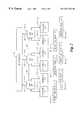
- FIG. 1is a functional block diagram of a security tag detection and localization system/according to a preferred embodiment of the present invention
- FIG. 2is a more detailed functional block diagram of the preferred embodiment of the present invention.
- FIG. 3is a functional block diagram of an electronic article security (EAS) sensor
- FIGS. 4 a-care diagrams illustrative of the various timing signals utilized by the preferred embodiment of the present invention.
- FIG. 5is a flow diagram describing the process for generating an alarm.
- FIG. 1a functional block diagram of a security tag detection and localization system 10 for detecting a resonant security tag 13 in a security zone 11 comprising a plurality of detection zones 18 (not shown) one of which is shown as 18 - 1 , 1 and localizing the resonant security tag 13 to one or more of the detection zones 18 .
- the tag detection and localization system 10comprises from one to N EAS sensors 12 , shown individually as 12 - 1 through 12 -N; an antenna array 17 comprising from one to n individual antennas connected to each EAS sensor 12 , shown individually as 17 - 1 , 1 through 17 -N, n; and an annunciator 14 .
- the security tag 13is of a type which is well known in the art of EAS systems having a resonant frequency vithin the frequency range of the EAS detection and localization system 10 with which the tag 13 is employed.
- the tag 13has a circuit Q of between 50 and 100 and resonates at or near a frequency of 8.2 MHz., which is a resonant frequency commonly employed by EAS systems from a number of manufacturers.
- the resonant frequency of a security tag 13has a tolerance of +/ ⁇ 10%, thus requiring each EAS sensor 12 to operate over a range of about 7.6 to 8.7 MHz.
- a security tag 13 having a resonant frequency of about 8.2 MHz.is not to be considered a limitation of the present invention.
- the security tag detection and localization system 10is suitable for operating at any frequency for which the security tag detection and localization system 10 is capable of establishing a suitable electromagnetic interaction between the antenna array 17 and the security tag 13 .
- the antenna array 17forms either the upper boundary of the security zone 11 , the lower boundary of the security zone 11 , or the antenna array 17 may be apportioned to both the upper and lower boundaries of the security zone 11 .
- the full horizontal extent of the combined upper and lower portions of the antenna arraydefines the approximate width and the approximate length of the security zone 11 .
- the antenna array 17is generally made integral with the floor.
- the antenna array 17could also be mounted beneath the floor or mounted above the surface of the floor.
- the array of antennas 17is located above the security zone 11 , it may be concealed in a ceiling or suspended beneath the ceiling, within the spirit and scope of the invention.
- the antenna array 17comprises at least two antennas, the antennas 17 comprising each of the upper and the lower boundaries being disposed side-by side in a single horizontal plane.
- each individual antenna 17 - 1 , 1 , 17 -N, nis electromagnetically coupled to one of the detection zones 18 .
- the beams of the individual antennas 17 - 1 , 1 , 17 -N, nilluminate adjoining detection zones 18 , which may also overlap, depending on the specific shape of the beams of the individual antennas 17 .
- the antennas 17are combined transmitting and receiving loop-type antennas of a kind which do not create a null in the far field of the major beam of the antenna and are of a conventional design well known to those skilled in the art. As will be appreciated by those skilled in the art, it is not required to use the same antenna 17 for transmitting and receiving. Separate transmitting and receiving antennas 17 could be used, within the spirit and scope of the invention. Further, the type of antenna 17 is not limited to a non-nulling loop-type antenna. Any type of antenna 17 having a beam shape commensurate with the desired size and shape of the detection zones 18 is within the spirit and scope of the invention.
- the security tag detection and localization system 10also includes one or more electronic article security (EAS) sensors 12 for transmitting interrogation signals to the antenna array 17 , receiving response signals from the antenna array 17 and generating an alarm signal localizing the security tag 13 to a detection zone 18 .
- EASelectronic article security
- FIG. 2there is shown a preferred embodiment having three EAS sensors 12 - 1 , 12 - 2 and 12 - 3 , each of which is connected to two antennas 17 - 1 , 1 , 17 - 1 , 2 ; 17 - 2 , 1 , 17 - 2 , 2 ; and 17 - 3 , 1 , 17 - 3 , 2 .
- the detection zones 18 of adjoining antennas 17overlap, giving rise to an alarm signal on signal lines 32 which may correspond to a single detection zone 18 or to adjoining detection zones 18 .
- the annunciator 14localizes a security tag 13 to more than one detection zone 18 .
- a slave signal line 30for synchronizing the separate EAS sensors 12 , as discussed in more detail below.
- the number of EAS sensors 12 that could be included in a single security tag detection and localization system 10is not limited to three and may be greater or less than three.
- the number of antennas 17 which could be connected to each EAS sensor 12is not limited to two and could be greater or less than two, and still be within the spirit and scope of the invention.
- the electronic article security sensor 12further includes an annunciator 14 connected to each EAS sensor 12 , for receiving the alarm signal over alarm signal lines 32 and for indicating the detection zone 18 corresponding to the alarm signal.
- the annunciator 14is a series of lamps (not shown), each lamp uniquely associated with a single detection zone 18 and emitting visible light when a security tag 13 is detected and localized to a detection zone 18 corresponding to the lamp.
- the method of annunciation provided by annunciator 14is not limited to visual annunciation. Other methods for annunciation could be used including, but not limited to, a combined audio and visual display, or a TV type display, within the spirit and scope of the invention.
- the preferred embodiment of the EAS sensor 12 - 1representative of the EAS sensors 12 , comprises a transmitter 20 for generating an interrogation signal and providing the interrogation signal to an antenna switch 26 , and a receiver 24 , synchronized with the transmitter 20 , for receiving a response signal from the antenna switch 26 and generating an output signal.
- the EAS sensor 12 - 1further includes antennas 17 - 1 , 1 and 17 - 1 , 2 for receiving the interrogation signal from the antenna switch 26 and radiating the interrogation signal into the security zone 11 , and receiving the response signal re-radiated from a security tag 13 located in one of the detection zones 18 and providing the response signal to the receiver 24 .
- the EAS sensor 12 - 1also includes the antenna switch 26 , connecting each EAS sensor 12 to the antennas 17 - 1 , 1 and 17 - 1 , 2 and a digitally controlled frequency synthesizer (DCFS) 22 for providing a carrier output signal which tunes the transmitter 20 to a transmitting frequencv and tunes the receiver 22 to a receiving frequency.
- DCFSdigitally controlled frequency synthesizer
- the transmitter 20 , the DCFS 22 , the receiver 24 and the antenna switch 26are conventional in design and well known to those skilled in the art, and therefore need not be described in detail for a complete understanding of the present invention.
- the preferred embodimentalso includes a controller 40 for setting the frequency of the carrier output signals generated by the DCFS 22 and for providing timing signals to the DCFS 22 , the transmitter 20 , the receiver 24 and the antenna switch 26 for determining the time for transmission and reception of the interrogation and response signals respectively.
- the controller 40includes a digital signal processor (DSP) 52 for executing the principal control and computational tasks of the controller 40 .
- DSPdigital signal processor
- the controller 40also includes a programmable read only memory (PROM) 50 for storing a computer program and table data, a random access memory (RAM) 54 for storing temporary data and a programmable logic device (PLD) 56 for interfacing the controller 40 to the DCFS 22 , the transmitter 20 , the receiver 24 and the antenna switch 26 .
- PROMprogrammable read only memory
- RAMrandom access memory
- PLDprogrammable logic device
- the controller 40further includes an analog-to-digital converter 58 for accepting the (analog) output signal from the receiver 24 , converting the output signal from the receiver 24 into a digital representation and inputting the digital representation of the output signal from the receiver 24 into the controller 40 . Additionally, the controller 40 includes an input/output device 60 for interfacing the controller 40 to the annunciator 14 over the alarm signal lines 32 and to other EAS sensors 12 over timing signal lines 42 , 44 and blocking signal lines 46 , 48 .
- the DSP 52executes a program stored in the PROM 50 to generate command signals responsive to parameters also stored in the PROM 50 .
- the PLD 56generates control signals for tuning the DCFS 22 to the correct transmitting and receiving frequencies based upon the command signals received from the DSP 52 and activates the transmitter 20 and the receiver 24 during the transmission and reception time periods.
- the structure of the controller 40is not limited to that disclosed in FIG. 3 .
- different storage devices and interface devicescould be used, and still be within the spirit and scope of the invention.
- the EAS sensor 12employs a technique known to those skilled in the art as the pulse-listen technique, typified by the StrataTM System, manufactured by Checkpoint Systems, Inc. of Thorofare, N.J. for detecting and localizing a resonant security tag 13 to a specific portion of the security zone 11 .
- the transmitter 20generates an interrogation signal comprising a repeating sequence of discrete frequency, burst type RF signals over a range of RF frequencies, such that the RF frequency of at least one burst falls near the resonant frequency of the resonant security tag 13 to be detected.
- the receiver 24receives a response signal re-radiated from the resonant security tag 13 as a result of a resonant circuit in the security tag 13 interacting with the preceding RF burst.
- the antenna switch 26sequentially selects pair-wise permutations, with replacement, of the antennas 17 connected to each EAS sensor 12 such that for each selected pair of antennas 17 , one antenna transmits the interrogation signal and one antenna 17 receives the response signal and each permutation of the pair of antennas 17 is selected only once over a predetermined time interval.
- the amplitude of the output of the receiver 24 resulting from each permutation of the pairs of antennas 17is compared in the DSP 52 for each frequency generated by the DCFS 22 .
- the location of the security tag 13is determined to correspond with the portion of the security zone 11 in the closest proximity to the pair of antennas 17 having the output signal of the receiver 24 with the largest amplitude.
- the number of permutations with replacement, of the antennas 17is computed by the formula n k , where n is the number of antennas connected to an EAS sensor 12 , and k is the number of antennas to be selected for each permutation.
- nis the number of antennas connected to an EAS sensor 12
- kis the number of antennas to be selected for each permutation.
- each EAS sensor 12operates in accordance with a frame interval.
- the frame interval 200(FIG. 4 a ) is divided into as many subframe intervals 202 as there are antennas 17 connected to the EAS sensor 12 for receiving.
- Within each subframe interval 202there is a period of transmission and reception 204 consisting of further subdivisions called bins 206 (FIG. 4 b ).
- Each bin 206provides for an EAS sensor 12 transmission and reception at a different frequency, the span of frequencies corresponding to the combined frequency uncertainty of the security tag 13 and the EAS sensor 12 .
- FIG. 4 aThe frame interval 200
- the frame interval 200(FIG. 4 a ) is divided into as many subframe intervals 202 as there are antennas 17 connected to the EAS sensor 12 for receiving.
- Within each subframe interval 202there is a period of transmission and reception 204 consisting of further subdivisions called bins 206 (FIG. 4 b ).
- Each bin 206provides for an EAS sensor 12 transmission and reception at
- each bin 206is further divided into as many sub-bins 208 as there are antennas 17 connected to the EAS sensor 12 for transmitting, with each sub-bin 208 having a noise reception period 210 , an interrogation transmission period 212 and a response signal transmission period 214 .
- there are two subframe intervals 202 per frame interval 200each subframe interval 202 having sixteen bins 206 with two sub-bins 208 per bin 206 .
- receptionis from antenna 17 - 1 , 1 and transmission is from antenna 17 - 1 , 1 (phase A) and antenna 17 - 1 , 2 (Phase B).
- receptionis from antenna 17 - 1 , 2 and transmission is from antennas 17 - 1 , 1 (Phase C) and 17 - 1 , 2 (Phase D).
- the antenna 17 connections for one frame 200 of transmission and reception for the preferred embodiment of the security tag detection and localization system 10 consisting of three EAS sensors 12are shown in Table I.
- the number of antennas 17 that may be connected to each EAS sensor 12may be greater than two. As will be appreciated by those skilled in the art, if more than two antennas 17 are connected to the EAS sensor 12 , the number of subframes and the number of sub-bins are increased according to the number of the receiving and the transmitting antennas respectively. Accordingly, EAS sensors 12 having a greater number of subframes per frame and sub-bins per bin than two are within the spirit and scope of the invention.
- the Security Tag Detection and Localization System 10is not limited to employing the pulse-listen technique.
- the well known EAS techniquewhereby the EAS sensor 10 sweeps the transmission frequency over the RF band of interest, either continuously or in discrete steps, could also be employed, within the spirit and scope of the invention.
- RF signal input and output lines 34 , 36are RF signal input and output lines 34 , 36 , timing signal input and output lines 42 , 44 and blocking signal input and output lines 46 , 48 interconnecting the EAS sensors 12 , corresponding collectively to the slave signal line 30 shown in FIG. 2 .
- the method for interconnecting the EAS sensors 12is by daisy-chaining the RF signal lines 34 , 36 , the timing signal lines 42 , 44 and the blocking signal lines 34 , 36 between the separate EAS sensors 12 .
- any type of interconnection methodsuch as bus type methods, is within the spirit and scope of the invention.
- one EAS sensor 12is arbitrarily selected as a master for distributing the RF carrier output signal from the DCFS 22 to all the other EAS sensors 12 , hereinafter called slave EAS sensors 12 . Accordingly, the RF carrier output signal ofthe DCFS 22 is provided over RF output signal line 34 to the input line 36 of a slave EAS sensor 12 .
- the slave EAS sensor 12provides the received RF carrier output signal to the transmitter 20 and receiver 24 and also outputs the received RF carrier signal to another slave EAS sensor 12 . In this manner, the transmitted interrogation signals for every EAS sensor 12 are maintained to be substantially in-phase with each other.
- the master EAS sensor 12provides timing signals for the frame 200 , subframe 202 , bin 206 , sub-bin 208 and transmitting and receiving periods 210 , 212 , 214 .
- the aforementioned timing signalsoriginate in PLD 56 , are distributed from the master EAS sensor 12 to the slave EAS sensors 12 such that the frames 200 , subframes 202 , bins 206 , sub-bins 208 and transmitting and receiving periods 210 , 212 , 214 of all the EAS sensors 12 are synchronized.
- the receiver 24 in each EAS sensor 12generates the received output signal corresponding to the amplitude of the response signal received by the receiver 24 for each permutation of the antennas 17 connected to the EAS sensor 12 and for each frequency generated by the DCFS 22 during each frame interval 200 .
- the receiver output signalis received by the analog-to-digital converter 58 and provided to the DSP 52 .
- the DSP 52For each frequency, the DSP 52 generates a detection signal corresponding to the largest receiver output signal, Sm, for each permutation of the antennas 17 for which the receiver output signal, So, exceeds a predetermined detection threshold, Td, for a predetermined number, Nd, of frame intervals 200 , signifying a valid detection of a security tag 13 in at least one detection zone 18 .
- the DSP 52includes an arbitrator 53 which arbitrates between the detection signal generated by the EAS sensor 12 , and a blocking signal having a predetermined duration, Tb, generated by another EAS sensor 12 .
- the arbitratorgenerates an alarm signal and the blocking signal if the detection signal is received by the arbitrator at a time when the blocking signal is not present.
- the arbitratorblocks the alarm of a second occurring detection by another EAS sensor 12 for the duration of the blocking signal.
- the duration of the blocking signalis about three seconds. It will be appreciated by those skilled in the art that the duration of the blocking signal is dictated by the particular configuration of the security tag detection and localization system 10 and may be other than about three seconds within the spirit and scope of the invention.
- the process for arbitration 100 of the preferred embodimentcomprising first setting a frame counter, FC, equal to a value of one (step 101 ) and receiving the output signal from the receiver 24 into the DSP 52 at step 102 .
- the largest output signal, Smfrom the receiver 24 is compared against the predetermined detection threshold, Td, step 103 . If the magnitude of the largest receiver output signal, Sm, exceeds the threshold value Td, the frame counter is advanced by one (step 104 ) and the value of the frame counter is compared to a predetermined duration, Nd, at step 105 .
- the arbitration process 100determines if a blocking signal has been received (step 106 ). If a blocking signal from another EAS sensor 12 has not been received, the alarm signal and the blocking signal of duration, Tb, are generated at step 107 , thereby blocking any alarms from other EAS sensors 12 for the duration of the blocking signal duration. If at step 103 , the output of the receiver 24 fails to satisfy the threshold criteria, Td, the frame counter is reset to a value of one.
- the frame counter, FCis reset to a value of one before comparing additional outputs from the receiver 24 with the detection threshold Td.
Landscapes
- Physics & Mathematics (AREA)
- Engineering & Computer Science (AREA)
- Automation & Control Theory (AREA)
- Electromagnetism (AREA)
- General Physics & Mathematics (AREA)
- Computer Security & Cryptography (AREA)
- Burglar Alarm Systems (AREA)
- Radar Systems Or Details Thereof (AREA)
- Mobile Radio Communication Systems (AREA)
- Alarm Systems (AREA)
Abstract
Description
| TABLE | ||||
| EAS # | ||||
| 1 | ||||
| TX Ant. | RX Ant. | TX Ant. | RX Ant. | TX Ant. | RX Ant. | ||
| 1, 1 | 1, 1 | 2, 1 | 2, 1 | 3, 1 | 3, 1 | |
| 1, 2 | 1, 1 | 2, 2 | 2, 1 | 3, 2 | 3, 1 | |
| 1, 1 | 1, 2 | 2, 1 | 2, 2 | 3, 1 | 3, 2 | |
| 1, 2 | 1, 2 | 2, 2 | 2, 2 | 3, 2 | 3, 2 | |
Claims (21)
Priority Applications (17)
| Application Number | Priority Date | Filing Date | Title |
|---|---|---|---|
| US09/472,395US6271756B1 (en) | 1999-12-27 | 1999-12-27 | Security tag detection and localization system |
| CA002396035ACA2396035A1 (en) | 1999-12-27 | 2000-12-07 | Security tag detection and localization system |
| IL15027300AIL150273A0 (en) | 1999-12-27 | 2000-12-07 | Security tag detection and localization system |
| AT00983962TATE360867T1 (en) | 1999-12-27 | 2000-12-07 | SYSTEM FOR DETECTING AND LOCATION OF SECURITY LABELS |
| ES00983962TES2284547T3 (en) | 1999-12-27 | 2000-12-07 | SYSTEM OF LOCATION AND DETECTION OF SECURITY LABELS. |
| BR0016746-0ABR0016746A (en) | 1999-12-27 | 2000-12-07 | Security tag detection and location system |
| DE60034591TDE60034591T2 (en) | 1999-12-27 | 2000-12-07 | SYSTEM FOR DETECTING AND LOCATING SAFETY LABELS |
| PCT/US2000/033093WO2001048718A1 (en) | 1999-12-27 | 2000-12-07 | Security tag detection and localization system |
| KR1020027008109AKR100682990B1 (en) | 1999-12-27 | 2000-12-07 | Security Tag Detection and Concentration System |
| CNB008177651ACN1252656C (en) | 1999-12-27 | 2000-12-07 | Detection and positioning system of alarm markers |
| MXPA02006418AMXPA02006418A (en) | 1999-12-27 | 2000-12-07 | Security tag detection and localization system. |
| CNA2005101025609ACN1744141A (en) | 1999-12-27 | 2000-12-07 | Security tag detection and localization system |
| EP00983962AEP1242985B1 (en) | 1999-12-27 | 2000-12-07 | Security tag detection and localization system |
| JP2001548365AJP2003518678A (en) | 1999-12-27 | 2000-12-07 | Security tag detection and localization system |
| AU20646/01AAU779305B2 (en) | 1999-12-27 | 2000-12-07 | Security tag detection and localization system |
| ARP000106927AAR031088A1 (en) | 1999-12-27 | 2000-12-26 | PROVISION OF DETECTION AND LOCATION OF SECURITY PROTECTIVE ELEMENTS AND ELECTRONIC SECURITY SENSOR OF ARTICLES |
| TW089127843ATW558688B (en) | 1999-12-27 | 2000-12-29 | Security tag detection and localization system |
Applications Claiming Priority (1)
| Application Number | Priority Date | Filing Date | Title |
|---|---|---|---|
| US09/472,395US6271756B1 (en) | 1999-12-27 | 1999-12-27 | Security tag detection and localization system |
Publications (1)
| Publication Number | Publication Date |
|---|---|
| US6271756B1true US6271756B1 (en) | 2001-08-07 |
Family
ID=23875352
Family Applications (1)
| Application Number | Title | Priority Date | Filing Date |
|---|---|---|---|
| US09/472,395Expired - Fee RelatedUS6271756B1 (en) | 1999-12-27 | 1999-12-27 | Security tag detection and localization system |
Country Status (16)
| Country | Link |
|---|---|
| US (1) | US6271756B1 (en) |
| EP (1) | EP1242985B1 (en) |
| JP (1) | JP2003518678A (en) |
| KR (1) | KR100682990B1 (en) |
| CN (2) | CN1252656C (en) |
| AR (1) | AR031088A1 (en) |
| AT (1) | ATE360867T1 (en) |
| AU (1) | AU779305B2 (en) |
| BR (1) | BR0016746A (en) |
| CA (1) | CA2396035A1 (en) |
| DE (1) | DE60034591T2 (en) |
| ES (1) | ES2284547T3 (en) |
| IL (1) | IL150273A0 (en) |
| MX (1) | MXPA02006418A (en) |
| TW (1) | TW558688B (en) |
| WO (1) | WO2001048718A1 (en) |
Cited By (23)
| Publication number | Priority date | Publication date | Assignee | Title |
|---|---|---|---|---|
| US20030209363A1 (en)* | 2002-05-08 | 2003-11-13 | Kadaster Ali G. | Method of and system for building structures and drilling oil and gas wells in arctic, inaccessible or environmentally sensitive locations |
| US20030216969A1 (en)* | 2002-01-23 | 2003-11-20 | Bauer Donald G. | Inventory management system |
| US20040011873A1 (en)* | 2002-04-11 | 2004-01-22 | Larry Canipe | System and method for optimizing range of an electronic article surveillance system |
| US6750771B1 (en)* | 2000-08-10 | 2004-06-15 | Savi Technology, Inc. | Antenna system and method for reading low frequency tags |
| US6825766B2 (en) | 2001-12-21 | 2004-11-30 | Genei Industries, Inc. | Industrial data capture system including a choke point portal and tracking software for radio frequency identification of cargo |
| US20050184872A1 (en)* | 2004-02-23 | 2005-08-25 | Clare Thomas J. | Identification marking and method for applying the identification marking to an item |
| US20050184873A1 (en)* | 2004-02-23 | 2005-08-25 | Eric Eckstein | Tag having patterned circuit elements and a process for making same |
| US20050183817A1 (en)* | 2004-02-23 | 2005-08-25 | Eric Eckstein | Security tag system for fabricating a tag including an integrated surface processing system |
| US20050183264A1 (en)* | 2004-02-23 | 2005-08-25 | Eric Eckstein | Method for aligning capacitor plates in a security tag and a capacitor formed thereby |
| US20060082510A1 (en)* | 2004-10-20 | 2006-04-20 | Checkpoint Systems, Inc. | Collapsible electronic article surveillance gate |
| US20060097874A1 (en)* | 2004-11-08 | 2006-05-11 | Checkpoint Systems, Inc. | System and method for detecting EAS/RFID tags using step listen |
| US20060253774A1 (en)* | 2002-08-19 | 2006-11-09 | Nederlandse Organisatie Voor Toegepastnatuurwetens Onderzoek Tno | Computer network protection |
| CN100342407C (en)* | 2001-08-23 | 2007-10-10 | Gsbs发展公司 | Fire detection system |
| US20090051534A1 (en)* | 2005-09-09 | 2009-02-26 | Sensormatic Electronics Corporation | Eas System Providing Synchronized Transmission |
| US7704346B2 (en) | 2004-02-23 | 2010-04-27 | Checkpoint Systems, Inc. | Method of fabricating a security tag in an integrated surface processing system |
| US20100148965A1 (en)* | 2008-12-16 | 2010-06-17 | Sensormatic Electronics Corporation | Method and system for item level uhf rfid tag with low frequency power assist |
| US8099335B2 (en) | 2004-02-23 | 2012-01-17 | Checkpoint Systems, Inc. | Method and system for determining billing information in a tag fabrication process |
| US8120540B1 (en) | 2008-06-06 | 2012-02-21 | The United States Of America As Represented By The Secretary Of The Navy | RF antenna system having low-power requirements for RFID tag communication |
| US8730044B2 (en) | 2002-01-09 | 2014-05-20 | Tyco Fire & Security Gmbh | Method of assigning and deducing the location of articles detected by multiple RFID antennae |
| CN105428272A (en)* | 2014-07-31 | 2016-03-23 | 北京北方微电子基地设备工艺研究中心有限责任公司 | Method and device for treating semiconductor device alarm |
| US9928703B2 (en)* | 2011-05-19 | 2018-03-27 | Invue Security Products Inc. | Systems and methods for protecting retail display merchandise from theft |
| US10276009B2 (en) | 2017-01-26 | 2019-04-30 | Hand Held Products, Inc. | Method of reading a barcode and deactivating an electronic article surveillance tag |
| US20220004834A1 (en)* | 2019-04-17 | 2022-01-06 | Apple Inc. | Antenna assembly for a wirelessly locatable tag |
Families Citing this family (5)
| Publication number | Priority date | Publication date | Assignee | Title |
|---|---|---|---|---|
| US7973663B2 (en)* | 2009-01-07 | 2011-07-05 | Sensomatic Electronics, LLC | Electronic article surveillance deactivator using visual pattern recognition system for triggering |
| US9547966B2 (en) | 2011-12-23 | 2017-01-17 | Yudigar S.L.U. | Uncoupling device and method |
| DE102012112858A1 (en)* | 2012-12-21 | 2014-06-26 | Rational Aktiengesellschaft | Method for monitoring a cooking appliance and cooking appliance with temperature sensor |
| CN109658657A (en)* | 2018-12-11 | 2019-04-19 | 成都威图芯晟科技有限公司 | Signal generating method, analysis method, detection method, relevant device and system |
| US11688272B2 (en)* | 2020-07-27 | 2023-06-27 | Sensormatic Electronics, LLC | Systems and methods of alternating transmitter for metal foil detection near moving doors |
Citations (8)
| Publication number | Priority date | Publication date | Assignee | Title |
|---|---|---|---|---|
| US4308530A (en) | 1977-07-19 | 1981-12-29 | N.V. Nederlandsche Apparatenfabriek Nedap | Detection system forming wide gates with superior spatial selectivity |
| US5051726A (en)* | 1990-08-14 | 1991-09-24 | Sensormatic Electronics Corporation | Electronic article surveillance system with antenna array for enhanced field falloff |
| US5103234A (en)* | 1987-08-28 | 1992-04-07 | Sensormatic Electronics Corporation | Electronic article surveillance system |
| US5648767A (en)* | 1994-11-30 | 1997-07-15 | Hughes Aircraft | Transponder detection system and method |
| US5661457A (en)* | 1995-06-19 | 1997-08-26 | Sensormatic Electronics Corporation | Directional antenna configuration for asset tracking system |
| US5708423A (en)* | 1995-05-09 | 1998-01-13 | Sensormatic Electronics Corporation | Zone-Based asset tracking and control system |
| US5815076A (en)* | 1996-01-16 | 1998-09-29 | Sensormatic Electronics Corporation | Pulsed-signal magnetomechanical electronic article surveillance system with improved damping of transmitting antenna |
| US6094173A (en)* | 1997-04-18 | 2000-07-25 | Motorola, Inc. | Method and apparatus for detecting an RFID tag signal |
- 1999
- 1999-12-27USUS09/472,395patent/US6271756B1/ennot_activeExpired - Fee Related
- 2000
- 2000-12-07BRBR0016746-0Apatent/BR0016746A/ennot_activeIP Right Cessation
- 2000-12-07ATAT00983962Tpatent/ATE360867T1/ennot_activeIP Right Cessation
- 2000-12-07CNCNB008177651Apatent/CN1252656C/ennot_activeExpired - Fee Related
- 2000-12-07MXMXPA02006418Apatent/MXPA02006418A/enactiveIP Right Grant
- 2000-12-07EPEP00983962Apatent/EP1242985B1/ennot_activeExpired - Lifetime
- 2000-12-07CNCNA2005101025609Apatent/CN1744141A/enactivePending
- 2000-12-07ILIL15027300Apatent/IL150273A0/enunknown
- 2000-12-07ESES00983962Tpatent/ES2284547T3/ennot_activeExpired - Lifetime
- 2000-12-07AUAU20646/01Apatent/AU779305B2/ennot_activeCeased
- 2000-12-07DEDE60034591Tpatent/DE60034591T2/ennot_activeExpired - Fee Related
- 2000-12-07KRKR1020027008109Apatent/KR100682990B1/ennot_activeExpired - Fee Related
- 2000-12-07WOPCT/US2000/033093patent/WO2001048718A1/enactiveIP Right Grant
- 2000-12-07CACA002396035Apatent/CA2396035A1/ennot_activeAbandoned
- 2000-12-07JPJP2001548365Apatent/JP2003518678A/enactivePending
- 2000-12-26ARARP000106927Apatent/AR031088A1/ennot_activeApplication Discontinuation
- 2000-12-29TWTW089127843Apatent/TW558688B/ennot_activeIP Right Cessation
Patent Citations (8)
| Publication number | Priority date | Publication date | Assignee | Title |
|---|---|---|---|---|
| US4308530A (en) | 1977-07-19 | 1981-12-29 | N.V. Nederlandsche Apparatenfabriek Nedap | Detection system forming wide gates with superior spatial selectivity |
| US5103234A (en)* | 1987-08-28 | 1992-04-07 | Sensormatic Electronics Corporation | Electronic article surveillance system |
| US5051726A (en)* | 1990-08-14 | 1991-09-24 | Sensormatic Electronics Corporation | Electronic article surveillance system with antenna array for enhanced field falloff |
| US5648767A (en)* | 1994-11-30 | 1997-07-15 | Hughes Aircraft | Transponder detection system and method |
| US5708423A (en)* | 1995-05-09 | 1998-01-13 | Sensormatic Electronics Corporation | Zone-Based asset tracking and control system |
| US5661457A (en)* | 1995-06-19 | 1997-08-26 | Sensormatic Electronics Corporation | Directional antenna configuration for asset tracking system |
| US5815076A (en)* | 1996-01-16 | 1998-09-29 | Sensormatic Electronics Corporation | Pulsed-signal magnetomechanical electronic article surveillance system with improved damping of transmitting antenna |
| US6094173A (en)* | 1997-04-18 | 2000-07-25 | Motorola, Inc. | Method and apparatus for detecting an RFID tag signal |
Cited By (42)
| Publication number | Priority date | Publication date | Assignee | Title |
|---|---|---|---|---|
| US6750771B1 (en)* | 2000-08-10 | 2004-06-15 | Savi Technology, Inc. | Antenna system and method for reading low frequency tags |
| CN100342407C (en)* | 2001-08-23 | 2007-10-10 | Gsbs发展公司 | Fire detection system |
| US6825766B2 (en) | 2001-12-21 | 2004-11-30 | Genei Industries, Inc. | Industrial data capture system including a choke point portal and tracking software for radio frequency identification of cargo |
| US8730044B2 (en) | 2002-01-09 | 2014-05-20 | Tyco Fire & Security Gmbh | Method of assigning and deducing the location of articles detected by multiple RFID antennae |
| US20030216969A1 (en)* | 2002-01-23 | 2003-11-20 | Bauer Donald G. | Inventory management system |
| US8321302B2 (en) | 2002-01-23 | 2012-11-27 | Sensormatic Electronics, LLC | Inventory management system |
| US20040011873A1 (en)* | 2002-04-11 | 2004-01-22 | Larry Canipe | System and method for optimizing range of an electronic article surveillance system |
| US20030209363A1 (en)* | 2002-05-08 | 2003-11-13 | Kadaster Ali G. | Method of and system for building structures and drilling oil and gas wells in arctic, inaccessible or environmentally sensitive locations |
| US20060253774A1 (en)* | 2002-08-19 | 2006-11-09 | Nederlandse Organisatie Voor Toegepastnatuurwetens Onderzoek Tno | Computer network protection |
| US7788481B2 (en)* | 2002-08-19 | 2010-08-31 | Nederlandse Organisatie voor toegepastnatuurweterns chappelijk Onderzoek TNO | Computer network protection |
| US7384496B2 (en) | 2004-02-23 | 2008-06-10 | Checkpoint Systems, Inc. | Security tag system for fabricating a tag including an integrated surface processing system |
| US20050183817A1 (en)* | 2004-02-23 | 2005-08-25 | Eric Eckstein | Security tag system for fabricating a tag including an integrated surface processing system |
| US7116227B2 (en) | 2004-02-23 | 2006-10-03 | Checkpoint Systems, Inc. | Tag having patterned circuit elements and a process for making same |
| US7119685B2 (en) | 2004-02-23 | 2006-10-10 | Checkpoint Systems, Inc. | Method for aligning capacitor plates in a security tag and a capacitor formed thereby |
| US20050184872A1 (en)* | 2004-02-23 | 2005-08-25 | Clare Thomas J. | Identification marking and method for applying the identification marking to an item |
| US7138919B2 (en) | 2004-02-23 | 2006-11-21 | Checkpoint Systems, Inc. | Identification marking and method for applying the identification marking to an item |
| US20050184873A1 (en)* | 2004-02-23 | 2005-08-25 | Eric Eckstein | Tag having patterned circuit elements and a process for making same |
| US20070113966A1 (en)* | 2004-02-23 | 2007-05-24 | Checkpoint Systems, Inc. | Process for forming at least a portion of a package or an envelope bearing a printed indicia |
| US20060175003A1 (en)* | 2004-02-23 | 2006-08-10 | Eric Eckstein | Security tag and system for fabricating a tag including an integrated surface processing system |
| US7368033B2 (en) | 2004-02-23 | 2008-05-06 | Checkpoint Systems, Inc. | Security tag and system for fabricating a tag including an integrated surface processing system |
| US20050183264A1 (en)* | 2004-02-23 | 2005-08-25 | Eric Eckstein | Method for aligning capacitor plates in a security tag and a capacitor formed thereby |
| US8099335B2 (en) | 2004-02-23 | 2012-01-17 | Checkpoint Systems, Inc. | Method and system for determining billing information in a tag fabrication process |
| US7856708B2 (en) | 2004-02-23 | 2010-12-28 | Checkpoint Systems, Inc. | Process for forming at least a portion of a package or an envelope bearing a printed indicia |
| US7704346B2 (en) | 2004-02-23 | 2010-04-27 | Checkpoint Systems, Inc. | Method of fabricating a security tag in an integrated surface processing system |
| US20060082510A1 (en)* | 2004-10-20 | 2006-04-20 | Checkpoint Systems, Inc. | Collapsible electronic article surveillance gate |
| US7489285B2 (en) | 2004-10-20 | 2009-02-10 | Checkpoint Systems, Inc. | Collapsible electronic article surveillance gate |
| US7148804B2 (en) | 2004-11-08 | 2006-12-12 | Checkpoint Systems, Inc. | System and method for detecting EAS/RFID tags using step listen |
| US20060097874A1 (en)* | 2004-11-08 | 2006-05-11 | Checkpoint Systems, Inc. | System and method for detecting EAS/RFID tags using step listen |
| US20090051534A1 (en)* | 2005-09-09 | 2009-02-26 | Sensormatic Electronics Corporation | Eas System Providing Synchronized Transmission |
| US8058994B2 (en)* | 2005-09-09 | 2011-11-15 | Sensormatic Electronics, LLC | EAS system providing synchronized transmission |
| US8120540B1 (en) | 2008-06-06 | 2012-02-21 | The United States Of America As Represented By The Secretary Of The Navy | RF antenna system having low-power requirements for RFID tag communication |
| US20100148965A1 (en)* | 2008-12-16 | 2010-06-17 | Sensormatic Electronics Corporation | Method and system for item level uhf rfid tag with low frequency power assist |
| US9928703B2 (en)* | 2011-05-19 | 2018-03-27 | Invue Security Products Inc. | Systems and methods for protecting retail display merchandise from theft |
| US10002505B1 (en) | 2011-05-19 | 2018-06-19 | Invue Security Products Inc. | Systems and methods for protecting retail display merchandise from theft |
| US10475307B2 (en) | 2011-05-19 | 2019-11-12 | Invue Security Products Inc. | Systems and methods for protecting retail display merchandise from theft |
| US11568721B2 (en) | 2011-05-19 | 2023-01-31 | Invue Security Products Inc. | Systems and methods for protecting retail display merchandise from theft |
| US12148273B2 (en) | 2011-05-19 | 2024-11-19 | Invue Security Products Inc. | Systems and methods for protecting retail display merchandise from theft |
| CN105428272A (en)* | 2014-07-31 | 2016-03-23 | 北京北方微电子基地设备工艺研究中心有限责任公司 | Method and device for treating semiconductor device alarm |
| CN105428272B (en)* | 2014-07-31 | 2019-03-12 | 北京北方华创微电子装备有限公司 | The method and device of semiconductor equipment alert process |
| US10276009B2 (en) | 2017-01-26 | 2019-04-30 | Hand Held Products, Inc. | Method of reading a barcode and deactivating an electronic article surveillance tag |
| US20220004834A1 (en)* | 2019-04-17 | 2022-01-06 | Apple Inc. | Antenna assembly for a wirelessly locatable tag |
| US12207726B2 (en)* | 2019-04-17 | 2025-01-28 | Apple Inc. | Antenna assembly for a wirelessly locatable tag |
Also Published As
| Publication number | Publication date |
|---|---|
| AU779305B2 (en) | 2005-01-13 |
| DE60034591D1 (en) | 2007-06-06 |
| MXPA02006418A (en) | 2002-11-29 |
| TW558688B (en) | 2003-10-21 |
| CN1252656C (en) | 2006-04-19 |
| EP1242985A1 (en) | 2002-09-25 |
| AR031088A1 (en) | 2003-09-10 |
| KR20020073486A (en) | 2002-09-26 |
| JP2003518678A (en) | 2003-06-10 |
| EP1242985B1 (en) | 2007-04-25 |
| CN1744141A (en) | 2006-03-08 |
| EP1242985A4 (en) | 2005-03-09 |
| DE60034591T2 (en) | 2008-01-03 |
| CA2396035A1 (en) | 2001-07-05 |
| WO2001048718A1 (en) | 2001-07-05 |
| CN1413342A (en) | 2003-04-23 |
| ES2284547T3 (en) | 2007-11-16 |
| ATE360867T1 (en) | 2007-05-15 |
| AU2064601A (en) | 2001-07-09 |
| BR0016746A (en) | 2002-09-03 |
| IL150273A0 (en) | 2002-12-01 |
| KR100682990B1 (en) | 2007-02-15 |
Similar Documents
| Publication | Publication Date | Title |
|---|---|---|
| US6271756B1 (en) | Security tag detection and localization system | |
| US4870391A (en) | Multiple frequency theft detection system | |
| AU763603B2 (en) | Electronic article security system employing variable time shifts | |
| US20080284593A1 (en) | Method and system for power management of electronic article surveillance systems | |
| US8576045B2 (en) | Synchronization of electronic article surveillance systems having metal detection | |
| JPH04290198A (en) | Disturbance device for article electron monitoring system | |
| AU2001259460B2 (en) | EAS system with wide exit coverage and reduced over-range | |
| CA2668543C (en) | Electronic article surveillance system synchronization using global positioning satellite signal | |
| CA2621490C (en) | Eas system providing synchronized transmission | |
| AU2001259460A1 (en) | EAS system with wide exit coverage and reduced over-range | |
| WO1984004191A1 (en) | A theft protection system particularly for shop areas | |
| HK1133109A (en) | Electronic article surveiliance system synchronization using global positioning satellite signal | |
| HK1139231A (en) | Method and system for power management of electronic article surveillance systems | |
| AU2012201596A1 (en) | Electronic article surveillance system synchronization using global positioning satellite signal |
Legal Events
| Date | Code | Title | Description |
|---|---|---|---|
| AS | Assignment | Owner name:CHECKPOINT SYSTEMS, INC., NEW JERSEY Free format text:ASSIGNMENT OF ASSIGNORS INTEREST;ASSIGNORS:DAVIES, JOHN E., JR.;ECKSTEIN, ERIC A.;HOPTON, EDWIN H. , JR.;AND OTHERS;REEL/FRAME:010509/0744 Effective date:19991222 | |
| AS | Assignment | Owner name:CHECKPOINT SYSTEMS, INC. (A PENNSYLVANIA CORPORATI Free format text:CORRECTIVE ASSIGNMENT TO CORRECT RECEIVING PARTY'S ADDRESS. AN ASSIGNMENT PREVIOUSLY RECORDED AT REEL 010509, FRAME 0744;ASSIGNORS:DAVIES, JOHN E. JR.;ECKSTEIN, ERIC A.;HOPTON, EDWIN H. JR.;AND OTHERS;REEL/FRAME:010748/0857 Effective date:19991222 | |
| FEPP | Fee payment procedure | Free format text:PAYOR NUMBER ASSIGNED (ORIGINAL EVENT CODE: ASPN); ENTITY STATUS OF PATENT OWNER: LARGE ENTITY | |
| FPAY | Fee payment | Year of fee payment:4 | |
| REMI | Maintenance fee reminder mailed | ||
| AS | Assignment | Owner name:WACHOVIA BANK, NATIONAL ASSOCIATION, AS ADMINISTRA Free format text:NOTICE OF GRANT OF SECURITY INTEREST IN PATENTS;ASSIGNOR:CHECKPOINT SYSTEMS, INC.;REEL/FRAME:022634/0888 Effective date:20090430 | |
| LAPS | Lapse for failure to pay maintenance fees | ||
| STCH | Information on status: patent discontinuation | Free format text:PATENT EXPIRED DUE TO NONPAYMENT OF MAINTENANCE FEES UNDER 37 CFR 1.362 | |
| FP | Lapsed due to failure to pay maintenance fee | Effective date:20090807 | |
| AS | Assignment | Owner name:CHECKPOINT SYSTEMS, INC., NEW JERSEY Free format text:TERMINATION OF SECURITY INTEREST IN PATENTS;ASSIGNOR:WELLS FARGO BANK, NATIONAL ASSOCIATION, SUCCESSOR-BY-MERGER TO WACHOVIA BANK, NATIONAL ASSOCIATION, AS ADMINISTRATIVE AGENT;REEL/FRAME:024723/0187 Effective date:20100722 |