US6271042B1 - Biochip detection system - Google Patents
Biochip detection systemDownload PDFInfo
- Publication number
- US6271042B1 US6271042B1US09/140,164US14016498AUS6271042B1US 6271042 B1US6271042 B1US 6271042B1US 14016498 AUS14016498 AUS 14016498AUS 6271042 B1US6271042 B1US 6271042B1
- Authority
- US
- United States
- Prior art keywords
- samples
- biochip
- light source
- sensor
- ccd sensor
- Prior art date
- Legal status (The legal status is an assumption and is not a legal conclusion. Google has not performed a legal analysis and makes no representation as to the accuracy of the status listed.)
- Expired - Fee Related
Links
Images


Classifications
- G—PHYSICS
- G01—MEASURING; TESTING
- G01N—INVESTIGATING OR ANALYSING MATERIALS BY DETERMINING THEIR CHEMICAL OR PHYSICAL PROPERTIES
- G01N21/00—Investigating or analysing materials by the use of optical means, i.e. using sub-millimetre waves, infrared, visible or ultraviolet light
- G01N21/62—Systems in which the material investigated is excited whereby it emits light or causes a change in wavelength of the incident light
- G01N21/63—Systems in which the material investigated is excited whereby it emits light or causes a change in wavelength of the incident light optically excited
- G01N21/64—Fluorescence; Phosphorescence
- G01N21/645—Specially adapted constructive features of fluorimeters
- G01N21/6452—Individual samples arranged in a regular 2D-array, e.g. multiwell plates
- B—PERFORMING OPERATIONS; TRANSPORTING
- B01—PHYSICAL OR CHEMICAL PROCESSES OR APPARATUS IN GENERAL
- B01J—CHEMICAL OR PHYSICAL PROCESSES, e.g. CATALYSIS OR COLLOID CHEMISTRY; THEIR RELEVANT APPARATUS
- B01J2219/00—Chemical, physical or physico-chemical processes in general; Their relevant apparatus
- B01J2219/00274—Sequential or parallel reactions; Apparatus and devices for combinatorial chemistry or for making arrays; Chemical library technology
- G—PHYSICS
- G01—MEASURING; TESTING
- G01N—INVESTIGATING OR ANALYSING MATERIALS BY DETERMINING THEIR CHEMICAL OR PHYSICAL PROPERTIES
- G01N21/00—Investigating or analysing materials by the use of optical means, i.e. using sub-millimetre waves, infrared, visible or ultraviolet light
- G01N21/62—Systems in which the material investigated is excited whereby it emits light or causes a change in wavelength of the incident light
- G01N21/63—Systems in which the material investigated is excited whereby it emits light or causes a change in wavelength of the incident light optically excited
- G01N21/64—Fluorescence; Phosphorescence
- G01N2021/6417—Spectrofluorimetric devices
- G01N2021/6419—Excitation at two or more wavelengths
- G—PHYSICS
- G01—MEASURING; TESTING
- G01N—INVESTIGATING OR ANALYSING MATERIALS BY DETERMINING THEIR CHEMICAL OR PHYSICAL PROPERTIES
- G01N21/00—Investigating or analysing materials by the use of optical means, i.e. using sub-millimetre waves, infrared, visible or ultraviolet light
- G01N21/62—Systems in which the material investigated is excited whereby it emits light or causes a change in wavelength of the incident light
- G01N21/63—Systems in which the material investigated is excited whereby it emits light or causes a change in wavelength of the incident light optically excited
- G01N21/64—Fluorescence; Phosphorescence
- G01N21/6428—Measuring fluorescence of fluorescent products of reactions or of fluorochrome labelled reactive substances, e.g. measuring quenching effects, using measuring "optrodes"
- G01N2021/6439—Measuring fluorescence of fluorescent products of reactions or of fluorochrome labelled reactive substances, e.g. measuring quenching effects, using measuring "optrodes" with indicators, stains, dyes, tags, labels, marks
- G01N2021/6441—Measuring fluorescence of fluorescent products of reactions or of fluorochrome labelled reactive substances, e.g. measuring quenching effects, using measuring "optrodes" with indicators, stains, dyes, tags, labels, marks with two or more labels
Definitions
- the inventionrelates to the field of detectors for analysis of biological samples located on biochips. More particularly, the invention relates to the field of detectors that analyze samples labeled with a tag while utilizing a charge coupled device sensor.
- Detection devicesthat detect and locate samples contained on a biochip via laser light sources and laser scanners are well known in the art. These detection devices require that the samples be labeled by a fluorescent tag. Typically, these detection devices rely on laser light sources to excite the samples that are labeled by a fluorescent tag and causes biologically active samples to output emitted light waves. The laser source is scanned to serially excite each sample on the biochip to detect any emitted light waves from the samples that are biologically active.
- laser scanners utilized to detect the emitted light waves from the exited samples on the biochiptypically require wait times upwards of five minutes for sufficient resolution. Because laser scanners operate as a serial scanning device by sequentially detecting one sample at a time on the surface of the biochip, laser scanners are inherently inefficient at detecting the emitted light waves from an array of samples.
- laser light sources utilized within the detection devicesinherently only emit coherent light waves which span over an extremely narrow range of wavelengths.
- Fluorescent tagsare generally responsive to a single frequency of light or light from a narrow frequency band.
- the use of the laser light sourcesseverely limits the flexibility of those detection devices because only one type of fluorescent tag can be used.
- additional laser sourcesmust be used.
- the prior art's long duration scan cyclemust be performed for each one of the required laser sources.
- the inventionis a biochip detection system for detecting and locating samples that are labeled with multiple tags and are located on a biochip.
- This biochip detection systemincludes a charge coupled device (CCD) sensor, a broad spectrum light source, a lens, a light source filter, and a sensor filter.
- the CCD sensorcomprises two dimensional CCD arrays to simultaneously detect light waves from at least a substantial portion of the biochip.
- the broad spectrum light sourceis optically coupled to the CCD sensor and is configured to be utilized with a variety of different fluorescent tags which have differing excitation wavelengths.
- the light source filteris optically coupled between the light source and the biochip and is configured to only substantially allow light waves that have an excitation wavelength corresponding to a particular fluorescent tag to reach the biochip.
- the light source filterprevents light waves that have similar wavelengths to an emission wavelength of the particular fluorescent tag from reaching the biochip or the CCD sensor.
- the sensor filteris optically coupled between the biochip and the CCD sensor and is configured to only substantially allow light waves that have the emission wavelength corresponding to the fluorescent tag to reach the CCD sensor. The sensor filter prevents extraneous light waves from giving the CCD sensor false signals.
- the lens and the CCD sensorare optimized and matched to each other such that the sensor operates at or below the diffraction rating of the lens. Further, the resolution of the CCD sensor is matched to the samples on the biochip such that the CCD sensor oversamples each of the samples a sufficient number of times. Additionally, the lens is configured to frame at least a substantial portion of the biochip.
- the biochip detection systemis optimized to provide a higher dynamic range, increased sensitivity, and faster throughput compared to system utilizing laser scanners. Further, the biochip detection system is capable of utilizing a same broad spectrum light source to excite samples labeled with a variety of fluorescent tags.
- FIG. 1illustrates a schematic side view of internal elements of the preferred embodiment of the present invention.
- FIG. 2illustrates a schematic side view of the preferred embodiment configured to analyze two sets of samples on a single biochip with each set of samples labeled with a different fluorescent tag.
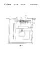
- FIG. 3illustrates a schematic side view of the preferred embodiment configured to analyze a plurality of samples on a single biochip with the plurality of samples labeled with multiple fluorescent tags.
- FIG. 4is a graph that illustrates a relationship between a light intensity versus a wavelength of an excitation light of a particular fluorescent tag, an emitted light of this particular fluorescent tag, and the source light as utilized in the present invention.
- FIG. 5illustrates a top view of an external housing of an alternate embodiment.
- FIG. 6illustrates a side view of the external housing of the alternate embodiment.
- FIG. 7illustrates a perspective view of the external housing of the alternate embodiment.
- FIG. 8illustrates a side view of a camera housing of the preferred embodiment.
- FIG. 1illustrates a side view of the preferred embodiment of the present invention.
- This preferred embodimentis a biochip detection system 100 as shown in FIG. 1 .
- the biochip detection system 100preferably includes a lens 120 , a sensor filter 130 , a charge coupled device (CCD) sensor 140 , a light source 150 , and a light source filter 160 .
- the biochip detection system 100is configured to detect and locate samples 110 within a biochip 170 .
- the samples 110 and the biochip 170are shown for exemplary purposes only and are not intended to be part of the present invention.
- the biochip 170is configured to have an array of samples 110 arranged in a predetermined number of rows and columns on top of a substrate.
- the samples 110 contained within the biochip 170are capable of including DNA or other biological material.
- the samples 110are labeled with a tag.
- the biochip 170 in the preferred embodimentis configured to hold samples 110 which are labeled with multiple tags. However, it will be apparent to those skilled in the art to utilize samples 110 only labeled by one tag on the biochip 170 .
- the samples 110 in the preferred embodimentare labeled with a fluorescent tag. However, it will be apparent to those skilled in the art to substitute this fluorescent tag with a chemiluminescent tag, colormetric tag, or the like. The process of labeling samples with a tag is well known in the art.
- the biochip detection system 100detects and locates which ones of the plurality of samples 110 are fluorescently labeled within the biochip 170 .
- the biochip detection system 100operates by exciting the samples 110 labeled by a fluorescent tag with light waves having an excitation wavelength thereby generating samples 110 that emit light waves having an emitted wavelength.
- the CCD sensor 140simultaneously detects the light waves having the emitted wavelength from at least a portion of the biochip 170 . Specific elements and procedures of the biochip detection system 100 are described in detail below.
- the CCD sensor 140is preferably configured to include a two dimensional array of charge coupled devices.
- the biochip detection system 100is capable of simultaneously imaging either an entire area or a portion of the biochip 170 (depending on the size of the biochip 170 ) for light waves emitted by the samples 110 .
- the CCD sensor 140allows the biochip detection system 100 to complete the detection process in most cases well under one minute and in some cases in twenty-five seconds.
- the CCD sensor 140comprises cooled charge coupled devices. By having the charge coupled devices within the CCD sensor 140 cooled, background noise is reduced and signal clarity is maximized.
- the CCD sensor 140is manufactured by Sony Corporation having the model number ICX 038DLA. It will be apparent to those skilled in the art to utilize a different CCD sensor 140 .
- the light source 150is preferably a broad spectrum bulb that is configured to output light waves over a wide range of wavelengths.
- the light source 150is optically coupled to the biochip 170 . Because the light source 150 generates light waves over a wide range of wavelengths, the light source 150 is capable of forming light waves to excite samples labeled with a wide variety of fluorescent tags.
- the light source 150is manufactured by General Electric Corporation having the model number 150 Watt EKE. It will be apparent to those skilled in the art to select a different light source.
- the lens 120is preferably a compound lens that includes multiple lens elements.
- the lens 120is located in an optical path between the biochip 170 and the CCD sensor 140 .
- the lens 120transmits light waves emitted from the samples 110 to the CCD sensor 140 .
- the lens 120is capable of adjusting and optimizing a magnification parameter such that a desired portion of the biochip 170 is captured by the CCD sensor 140 with an appropriate field of view.
- the lens 120is configured such that the CCD sensor 140 operates at or below the diffraction limit of the lens 120 .
- the lens 120is manufactured by Fujinon having a focal length of 25 millimeters and f-stop of 1:0.85. It will be apparent to those skilled in the art that the lens 120 can be substituted for a different lens or multiple lenses.
- the light source filter 160is optically coupled between the light source 150 and the biochip 170 .
- the light source filter 160is preferably configured to substantially only allow light waves generated by the light source 150 with a predetermined excitation wavelength to reach the biochip 170 .
- the predetermined excitation wavelengthcorresponds to a particular wavelength that excites one of the samples 110 that is labeled with a particular fluorescent tag.
- the predetermined excitation wavelengthdepends on the sample in conjunction with the fluorescent tag.
- the light source filter 160substantially blocks all light waves from the light source 150 with wavelengths other than the predetermined excitation wavelength from reaching the biochip 170 . By blocking substantially all light waves that have wavelengths other than the predetermined excitation wavelength, the light source filter 160 prevents erroneous light waves generated by the light source 150 from giving the CCD sensor 140 erroneous signals.
- the sensor filter 130is optically coupled between the CCD sensor 140 and the biochip 170 .
- the sensor filter 130is preferably between the CCD sensor 140 and the lens 120 .
- the sensor filter 130also can be configured between the lens 120 and the biochip 170 .
- the sensor filter 130is preferably configured to substantially only allow light waves that are emitted from a sample labeled with a particular fluorescent tag that has a predetermined emitted wavelength to reach the CCD sensor 140 .
- the predetermined emitted wavelengthoccurs during excitation of this sample and depends on the sample in conjunction with the particular fluorescent tag.
- the sensor filter 130is optimized to parameters of the light source 150 and prevents extraneous light waves from reaching the CCD sensor 140 thereby increasing the accuracy and sensitivity of the biochip detection system 100 . It will be apparent to those of ordinary skill in the art that the filter selection is made to correspond with the fluorescent tags and also the sample type.
- the biochip detection system 100is capable of efficiently detecting and locating samples 110 on the biochip 170 .
- the CCD sensor 140 and the lens 120are preferably optimized relative to each other and also to the samples 110 on the biochip 170 .
- the CCD sensor 140preferably has a transmission resolution to oversample each of the samples 110 by eight to nine times.
- the CCD sensor 140is preferably configured to have each of the samples 110 be optically detected by eight to nine pixels.
- the lens 120is preferably optimized to allow the CCD sensor 140 to operate at or below the diffraction limit of the lens 120 .
- the biochip detection system 100is preferably configured to analyze the biochip 170 .
- the samples 110are contained within the biochip 170 and are labeled with a multiple fluorescent tags.
- the biochip detection system 100initiates operation by activating the light source 150 .
- the light waves emitted from the light source 150are represented with a light wave 180 in FIG. 1 .
- the light wave 180preferably passes through the light source filter 160 .
- a resultant light wave after passage through the light source filter 160is represented as a light wave 190 as shown in FIG. 1 .
- the light wave 190only substantially includes light waves with a predetermined excitation wavelength which correspondingly excites the samples 110 which are labeled with the particular fluorescent tag.
- the samples 110As the samples 110 are excited by the predetermined excitation wavelength in the light wave 190 , the samples 110 produce light waves which are represented by a light wave 200 as shown in FIG. 1 .
- the light wave 200preferably includes light waves with a predetermined emission wavelength which are produced by the samples 110 .
- the light wave 200then passes through the lens 120 .
- Some extraneous light waves with the predetermined excitation wavelengthalso pass through the lens 120 as shown by the light wave 190 .
- the sensor filter 130preferably blocks out substantially all light waves with wavelengths other than the predetermined emission wavelength; the sensor filter 130 substantially only allows light waves represented by the light wave 200 to reach the CCD sensor 140 .
- the CCD sensor 140is capable of accurately detecting and locating the samples 110 on the biochip 170 . As a result, the CCD sensor 140 is prevented from erroneously detecting stray light waves.
- the biochip detection system 100is capable of accommodating a variety of fluorescent tags without switching the light source 150 , the lens 120 , or the CCD sensor 140 .
- only the light source filter 160 and the emission filter 130are preferably changed.
- the biochip detection system 100is capable of detecting and locating the samples labeled by this new fluorescent tag.
- the light source filter 160is changed such that substantially only light waves with an excitation wavelength corresponding to a new fluorescent tag reach the samples labeled by this new fluorescent tag.
- the sensor filter 130is preferably changed such that substantially only light waves with an emission wavelength corresponding to the new fluorescent tag reach the CCD sensor 140 .
- FIG. 2illustrates the biochip detection system 100 configured to analyze a biochip 210 having two sets of samples with each set of samples labeled by a different fluorescent tag.
- the configuration of the biochip detection system 100which includes the light source 150 , the lens 120 , the sensor filters 130 and 130 ′, the light source filters 160 and 160 ′, and the CCD sensor 140 is similar to the biochip detection system 100 in FIG. 1 .
- the sensor filters 130 and 130 ′are used interchangeably, one each for detecting the presence of different fluorescent tags.
- the light source filters 160 and 160 ′are used interchangeably to illuminate the biochip 210 with different wavelengths of light. It will be apparent to those skilled in the art that additional filters can be utilized.
- the biochip 210contains a first set of samples 220 which is labeled by a first fluorescent tag, and a second set of samples 230 which is labeled by a second fluorescent tag.
- the biochip detection system 100is configured to locate and detect the first set of samples 220 .
- the source light filter 160preferably substantially only allows light waves with an excitation wavelength corresponding to the first fluorescent tag to reach the biochip 210 .
- the sensor filter 130preferably substantially only allows light waves with an emission wavelength corresponding to the first fluorescent tag to reach the CCD sensor 140 .
- the system 100is configured to detect and locate the second set of samples 230 .
- the source light filter 160 ′preferably substantially only allows light waves with an excitation wavelength corresponding to the second fluorescent tag to reach the biochip 210 .
- the sensor filter 130 ′preferably substantially only allows light waves with an emission wavelength corresponding to the second fluorescent tag to reach the CCD sensor 140 .
- the filtercan be manually changed.
- the filterscan be automatically interchanged, for example, using a so-called “jukebox”.
- first set of samples 220 and the second set of samples 230are described as being labeled with a fluorescent tag, it will be apparent to those skilled in the art to substitute a fluorescent tag with a chemiluminescent tag, colormetric tag, and the like.
- FIG. 3illustrates the biochip detection system 100 configured to analyze a biochip 700 having a plurality of samples 710 wherein each of the plurality of samples 710 are preferably labeled by multiple fluorescent tags.
- the configuration of the biochip detection system 100which includes the light source 150 , the lens 120 , the sensor filters 130 and 130 ′, the light source filters 160 and 160 ′, and the CCD sensor 140 remain identical to the biochip detection system 100 in FIG. 2 .
- the sensor filters 130 and 130 ′are used interchangeably, one each for detecting the presence of different fluorescent tags.
- the light source filters 160 and 160 ′are used interchangeably to illuminate the biochip 700 with different wavelengths of light. It will be apparent to those skilled in the art that additional filters can be utilized.
- the plurality of samples 710are represented as being labeled by a first fluorescent tag 720 and a second fluorescent tag 730 . It will be apparent to those with ordinary skill in the art to label the plurality of samples 710 with any number of tags.
- the biochip detection system 100is configured to locate and detect the plurality of samples 710 that are labeled with the first fluorescent tag 720 .
- the source light filter 160preferably substantially only allows light waves with an excitation wavelength corresponding to the first fluorescent tag to reach the biochip 700 .
- the sensor filter 130preferably substantially only allows light waves with an emission wavelength corresponding to the first fluorescent tag 720 to reach the CCD sensor 140 .
- the system 100is configured to detect and locate the plurality of samples 710 that are labeled with the second fluorescent tag 730 .
- the source light filter 160 ′preferably substantially only allows light waves with an excitation wavelength corresponding to the second fluorescent tag 730 to reach the biochip 700 .
- the sensor filter 130 ′preferably substantially only allows light waves with an emission wavelength corresponding to the second fluorescent tag 730 to reach the CCD sensor 140 . The filter can be manually changed.
- the filterscan be automatically interchanged, for example, using a so-called “jukebox”.
- the plurality of samples 710are described as being labeled with multiple fluorescent tags, it will be apparent to those skilled in the art to substitute multiple fluorescent tags with multiple chemiluminescent tags, colormetric tags, and the like.
- FIG. 4illustrates a graph representing intensity of light along the vertical axis and wavelength along the horizontal axis.
- a curve 300is representative of the light output from the light source 150 (FIGS. 1, 2 , and 3 ). As observed from the curve 300 , the light source 150 outputs light waves preferably at an uniform intensity over a range of wavelengths.
- a curve 310is centered around ⁇ Exicited and represents a desired light intensity and wavelength to strike a sample labeled with a particular fluorescent tag in order to excite this sample.
- a curve 320is centered around ⁇ Excited and represents an emitted light intensity and wavelength from this sample while this sample is excited by light waves represented by the curve 310 .
- the curves 300 , 310 , and 320illustrate the functions of the light source filter 160 and the sensor filter 130 as illustrated in FIGS. 1, 2 , and 3 and as described above.
- the light source 150preferably outputs light waves represented by the curve 300 .
- the light source filter 160substantially only allows light waves that have wavelengths centered around the ⁇ Excited to reach the sample labeled by this particular fluorescent tag. Consequently, these light waves that have wavelengths centered around the ⁇ Excited excite the sample and are represented by the curve 310 . While excited, this sample preferably emits light waves that have wavelengths centered around the ⁇ Emitted .
- the sensor filter 130substantially only allows light waves that have wavelengths centered around the ⁇ Emitted (which are represented by the curve 320 ) to reach the CCD sensor 140 .
- the source light filter 160prevents erroneous light waves from passing through the sensor filter 130 and striking the CCD sensor 140 . Further, by having the sensor filter 130 prevent light waves that have wavelengths centered around the ⁇ Excited from passing through the biochip 170 and then striking the CCD sensor 140 , the sensor filter 130 prevents erroneous readings from the CCD sensor 140 . As a result of the source light filter 160 and the sensor filter 130 , fewer or no stray, erroneous light waves strike the CCD sensor 140 .
- FIG. 5illustrates an external top view of an alternate embodiment of the biochip detection system 100 .
- a main housing 400is configured to hold the biochip 170 and the light source 150 .
- the main housing 400is also configured to be light proof. By being light proof, the main housing 400 prevents extraneous light waves from giving the CCD sensor 140 erroneous signals.
- At least one articulating mirror 410is utilized within the main housing 400 for appropriately directing light waves from the light source 150 to the biochip 170 .
- a camera housing 420is utilized to hold the CCD sensor 140 and coupled to the main housing 400 .
- FIG. 6illustrates an external side view of the alternate embodiment of the biochip detection system 100 .
- the main housing 400includes a drawer 440 which allows a user to change the biochip 170 , adjust the light source filter 160 , and/or adjust the light source 150 .
- the drawer 440includes appropriate seals to engage the main housing 400 such that the main housing 400 remains light proof.
- a filter box 480is coupled to the main housing 400 .
- the filter box 480is configured to securely hold the sensor filter 130 and has an opening 450 to accept the sensor filter 130 .
- the camera housing 420is mounted to the filter box 480 via a camera mounting bracket 430 .
- a light shield 510is mounted between the camera housing 420 and the filter box 480 to prevent stray light waves from entering either the camera housing 420 , the main housing 400 , or the filter box 480 .
- FIG. 7illustrates an external perspective view of the alternate embodiment of the biochip detection system 100 .
- the camera housing 420the camera mounting bracket 430 , and the light shield 510 are omitted from FIG. 6.
- a fiber optic port 490is provided in the main housing 400 .
- the fiber optic port 490allows the biochip detection system 100 to interface with an external light source which is capable of transmitting light via a fiber optic cable connected to the external light and the fiber optic port 490 .
- the filter box 480has a light channel 530 for allowing light to pass through the filter box 480 from the main housing 400 to the camera housing 420 . Further, the filter box 480 also has an opening 505 to accept a ball plunger 500 .
- a filter holder 460is configured to hold at least one sensor filter 130 and has a plurality of notches 520 .
- the filter holder 460is configured to slide through the opening 450 in the filter box 480 .
- the ball plunger 500is configured to engage one of the plurality of notches 520 to appropriately position the filter holder 460 relative to the filter box 480 .
- a preferred embodiment of the external housingis similar to the alternate embodiment as shown in FIGS. 5, 6 , and 7 .
- a main difference between the alternate embodiment and the preferred embodimentis that the preferred embodiment does not utilize the filter box 480 and the filter holder 460 as shown in FIGS. 5, 6 , and 7 .
- the preferred embodiment of the external housingpreferably couples the camera mount bracket 430 directly to the main housing 400 .
- the camera housing 420 as shown in FIGS. 5 and 6is modified and replaced in the preferred embodiment by a camera housing 600 .
- the camera housing 600is illustrated in FIG. 8 .
- the camera housing 600preferably contains a filter wheel 610 which holds at least one sensor filter 130 .
- the filter wheel 610optically couples the sensor filter 130 between the lens 120 and the CCD sensor 140 . Further, the filter wheel 610 is preferably configured to change positions thus allowing different sensor filters 130 to be optically coupled between the lens 120 and the CCD sensor 140 .
- the device of the present inventioncould be implemented in several different ways and the apparatus disclosed above is only illustrative of the preferred embodiment of the invention and is in no way a limitation. For example, it would be within the scope of the invention to vary the dimensions disclosed herein.
- the various aspects of the above-described inventioncan be utilized singly or in combination with one or more of the other aspects of the invention described herein.
- the various elements of the present inventioncould be substituted with other elements.
Landscapes
- Health & Medical Sciences (AREA)
- Nuclear Medicine, Radiotherapy & Molecular Imaging (AREA)
- Physics & Mathematics (AREA)
- Life Sciences & Earth Sciences (AREA)
- Chemical & Material Sciences (AREA)
- Analytical Chemistry (AREA)
- Biochemistry (AREA)
- General Health & Medical Sciences (AREA)
- General Physics & Mathematics (AREA)
- Immunology (AREA)
- Pathology (AREA)
- Investigating, Analyzing Materials By Fluorescence Or Luminescence (AREA)
- Investigating Or Analysing Biological Materials (AREA)
Abstract
Description
Claims (17)
Priority Applications (5)
| Application Number | Priority Date | Filing Date | Title |
|---|---|---|---|
| US09/140,164US6271042B1 (en) | 1998-08-26 | 1998-08-26 | Biochip detection system |
| EP99945286AEP1109936A1 (en) | 1998-08-26 | 1999-08-25 | Biochip detection system |
| JP2000567742AJP2002523761A (en) | 1998-08-26 | 1999-08-25 | Biochip detection system |
| PCT/US1999/019759WO2000012759A1 (en) | 1998-08-26 | 1999-08-25 | Biochip detection system |
| US09/882,912US20010031502A1 (en) | 1998-08-26 | 2001-06-15 | Biochip detection system |
Applications Claiming Priority (1)
| Application Number | Priority Date | Filing Date | Title |
|---|---|---|---|
| US09/140,164US6271042B1 (en) | 1998-08-26 | 1998-08-26 | Biochip detection system |
Related Child Applications (1)
| Application Number | Title | Priority Date | Filing Date |
|---|---|---|---|
| US09/882,912ContinuationUS20010031502A1 (en) | 1998-08-26 | 2001-06-15 | Biochip detection system |
Publications (1)
| Publication Number | Publication Date |
|---|---|
| US6271042B1true US6271042B1 (en) | 2001-08-07 |
Family
ID=22490018
Family Applications (2)
| Application Number | Title | Priority Date | Filing Date |
|---|---|---|---|
| US09/140,164Expired - Fee RelatedUS6271042B1 (en) | 1998-08-26 | 1998-08-26 | Biochip detection system |
| US09/882,912AbandonedUS20010031502A1 (en) | 1998-08-26 | 2001-06-15 | Biochip detection system |
Family Applications After (1)
| Application Number | Title | Priority Date | Filing Date |
|---|---|---|---|
| US09/882,912AbandonedUS20010031502A1 (en) | 1998-08-26 | 2001-06-15 | Biochip detection system |
Country Status (4)
| Country | Link |
|---|---|
| US (2) | US6271042B1 (en) |
| EP (1) | EP1109936A1 (en) |
| JP (1) | JP2002523761A (en) |
| WO (1) | WO2000012759A1 (en) |
Cited By (19)
| Publication number | Priority date | Publication date | Assignee | Title |
|---|---|---|---|---|
| US20010031502A1 (en)* | 1998-08-26 | 2001-10-18 | Watson Robert Malcolm | Biochip detection system |
| US6362006B1 (en)* | 2000-03-13 | 2002-03-26 | General Electric Company | Rapid parallel determination of non-volatile analytes in complex combinatorial samples |
| US20020066865A1 (en)* | 2000-12-05 | 2002-06-06 | Lung-Yu Hung | Matrix biochip sensing system |
| US20020123059A1 (en)* | 2001-03-05 | 2002-09-05 | Ho Winston Z. | Chemiluminescence-based microfluidic biochip |
| WO2003014400A1 (en)* | 2001-08-08 | 2003-02-20 | Applied Precision, Llc | Time-delay integration imaging of biological specimens |
| WO2003038413A1 (en)* | 2001-11-01 | 2003-05-08 | Diachip Co., Ltd. | Apparatus for analyzing florescent image of biochip |
| US6620623B1 (en) | 2002-05-06 | 2003-09-16 | The University Of Chicago | Biochip reader with enhanced illumination and bioarray positioning apparatus |
| US20040132218A1 (en)* | 2003-01-08 | 2004-07-08 | Ho Winston Z. | Self-contained microfluidic biochip and apparatus |
| US20040178370A1 (en)* | 2003-03-10 | 2004-09-16 | Oldham Mark F. | Combination reader |
| US6853454B1 (en) | 2004-01-15 | 2005-02-08 | Alpha Innotech Corporation | Optical analysis systems |
| US20050157385A1 (en)* | 2004-01-15 | 2005-07-21 | Heffelfinger David M. | Optical analysis systems |
| US20050157299A1 (en)* | 2004-01-15 | 2005-07-21 | Heffelfinger David M. | Optical analysis systems |
| WO2006031537A3 (en)* | 2004-09-09 | 2006-08-17 | Alpha Innotech Corp | Microplate analysis system and method |
| US20060186346A1 (en)* | 2005-02-18 | 2006-08-24 | Academia Sinica | Method and system for reading microarrays |
| CN1312476C (en)* | 2004-08-27 | 2007-04-25 | 清华大学 | Method and system for detecting biological chip by space phase modulation interference array |
| US20070279631A1 (en)* | 2006-05-31 | 2007-12-06 | The University Of Chicago | Modular, micro-scale, optical array and biodetection system |
| US20110255084A1 (en)* | 2010-04-15 | 2011-10-20 | Shuo-Ting Yan | Bio-sample image pickup device |
| CN106353320A (en)* | 2016-09-12 | 2017-01-25 | 北京纳迅科技股份有限公司 | Portable biochip reader |
| CN114384050A (en)* | 2020-10-16 | 2022-04-22 | 欧阳自坤 | Biological particle positioning sensing method and system |
Families Citing this family (35)
| Publication number | Priority date | Publication date | Assignee | Title |
|---|---|---|---|---|
| US6136541A (en) | 1999-02-22 | 2000-10-24 | Vialogy Corporation | Method and apparatus for analyzing hybridized biochip patterns using resonance interactions employing quantum expressor functions |
| US6142681A (en) | 1999-02-22 | 2000-11-07 | Vialogy Corporation | Method and apparatus for interpreting hybridized bioelectronic DNA microarray patterns using self-scaling convergent reverberant dynamics |
| AU5875900A (en) | 1999-06-18 | 2001-01-09 | Genomic Solutions, Inc. | An automated, ccd-based microarray imaging system |
| GB2368903A (en)* | 2000-11-08 | 2002-05-15 | Proimmune Ltd | Analysis of biological and biochemical assays |
| DE60225669T2 (en) | 2001-01-16 | 2009-04-23 | Given Imaging Ltd. | SYSTEM FOR DETERMINING IN VIVO CONDITIONS IN BODY LUMINA |
| US20040092001A1 (en)* | 2001-03-01 | 2004-05-13 | 3M Innovative Properties Company | Automated imaging and harvesting of colonies on thin film culture devices |
| CN100485032C (en) | 2001-05-11 | 2009-05-06 | 松下电器产业株式会社 | Biomolecule substrate, and inspection and diagnosis method and apparatus using the same |
| DE10321490B3 (en)* | 2002-02-05 | 2004-10-14 | Infineon Technologies Ag | Electrochemical sensor, as a biochip working on a redox cycling principle, has one circuit is a potentiostat coupled to the sensor electrode and a second circuit has a condenser for potential comparison |
| DE10204652B4 (en) | 2002-02-05 | 2004-07-22 | Infineon Technologies Ag | Circuit arrangement, electrochemical sensor, sensor arrangement and method for processing a current signal provided via a sensor electrode |
| JP2003294757A (en)* | 2002-03-29 | 2003-10-15 | Fuji Photo Film Co Ltd | Method of biochemical analysis |
| JP4038066B2 (en)* | 2002-03-29 | 2008-01-23 | 富士フイルム株式会社 | Biochemical analysis system and biochemical analysis method |
| EP1534120B1 (en)* | 2002-08-13 | 2010-06-09 | Given Imaging Ltd. | System for in vivo sampling and analysis |
| US20040102903A1 (en)* | 2002-11-27 | 2004-05-27 | Graessle Josef A. | Biological growth plate scanner |
| US20040101954A1 (en)* | 2002-11-27 | 2004-05-27 | Graessle Josef A. | Back side plate illumination for biological growth plate scanner |
| BRPI0316471B1 (en)* | 2002-11-27 | 2017-06-20 | 3M Innovative Properies Company | DEVICE AND METHOD FOR SQUARING BIOLOGICAL GROWING PLATES |
| US7319031B2 (en)* | 2002-11-27 | 2008-01-15 | 3M Innovative Properties Company | Mounting platform for biological growth plate scanner |
| US7351574B2 (en)* | 2002-11-27 | 2008-04-01 | 3M Innovative Properties Company | Loading and ejection systems for biological growth plate scanner |
| US7298885B2 (en)* | 2002-11-27 | 2007-11-20 | 3M Innovative Properties Company | Biological growth plate scanner with automated image processing profile selection |
| DE10315074A1 (en) | 2003-04-02 | 2004-10-14 | Clondiag Chip Technologies Gmbh | Device for the duplication and detection of nucleic acids |
| JP2007521477A (en)* | 2003-06-26 | 2007-08-02 | ギブン・イメージング・リミテツド | Method, apparatus and system for in vivo detection |
| US7460896B2 (en)* | 2003-07-29 | 2008-12-02 | Given Imaging Ltd. | In vivo device and method for collecting oximetry data |
| US7496225B2 (en) | 2003-09-04 | 2009-02-24 | 3M Innovative Properties Company | Biological growth plate scanner with automated intake |
| US7298886B2 (en) | 2003-09-05 | 2007-11-20 | 3M Innovative Properties Company | Counting biological agents on biological growth plates |
| DE102004022263A1 (en) | 2004-05-06 | 2005-12-15 | Clondiag Chip Technologies Gmbh | Apparatus and method for detecting molecular interactions |
| DE102005052752A1 (en) | 2005-11-04 | 2007-05-10 | Clondiag Chip Technologies Gmbh | Apparatus and method for detecting molecular interactions |
| DE102005052713A1 (en) | 2005-11-04 | 2007-05-16 | Clondiag Chip Tech Gmbh | Apparatus and method for detecting molecular interactions |
| US8484000B2 (en) | 2004-09-02 | 2013-07-09 | Vialogy Llc | Detecting events of interest using quantum resonance interferometry |
| AT502549B1 (en) | 2005-10-07 | 2007-06-15 | Anagnostics Bioanalysis Gmbh | DEVICE FOR THE ANALYSIS OF LIQUID SAMPLES |
| EP2078189B1 (en) | 2006-10-20 | 2012-10-10 | Clondiag GmbH | Assay devices and methods for the detection of analytes |
| DE102007031526B4 (en) | 2007-07-06 | 2010-07-08 | Fraunhofer-Gesellschaft zur Förderung der angewandten Forschung e.V. | Use of an anode in a fuel cell for the oxidation of ethanol and / or at least one C3 to C10-containing alcohol |
| WO2009111301A1 (en)* | 2008-03-04 | 2009-09-11 | 3M Innovative Properties Company | Information management in automated processing of biological growth media |
| US9933446B2 (en)* | 2008-03-04 | 2018-04-03 | 3M Innovative Properties Company | Processing of biological growth media based on measured manufacturing characteristics |
| US8515507B2 (en) | 2008-06-16 | 2013-08-20 | Given Imaging Ltd. | Device and method for detecting in-vivo pathology |
| WO2010065538A1 (en)* | 2008-12-02 | 2010-06-10 | The Regents Of The University Of California | Imaging arrangement and microscope |
| CN105548179A (en)* | 2015-12-04 | 2016-05-04 | 深圳市赛尔生物技术有限公司 | Method and system for determination of biochip based on transmitted light or self luminescence |
Citations (56)
| Publication number | Priority date | Publication date | Assignee | Title |
|---|---|---|---|---|
| US4415732A (en) | 1981-03-27 | 1983-11-15 | University Patents, Inc. | Phosphoramidite compounds and processes |
| US4458066A (en) | 1980-02-29 | 1984-07-03 | University Patents, Inc. | Process for preparing polynucleotides |
| US4537861A (en)* | 1983-02-03 | 1985-08-27 | Elings Virgil B | Apparatus and method for homogeneous immunoassay |
| US4816513A (en) | 1984-03-23 | 1989-03-28 | Applied Biosystems, Inc. | Automated polypeptide synthesis process |
| US5047524A (en) | 1988-12-21 | 1991-09-10 | Applied Biosystems, Inc. | Automated system for polynucleotide synthesis and purification |
| US5053454A (en) | 1989-02-15 | 1991-10-01 | Sri International | Multiple polymer synthesizer |
| US5091652A (en)* | 1990-01-12 | 1992-02-25 | The Regents Of The University Of California | Laser excited confocal microscope fluorescence scanner and method |
| US5093268A (en) | 1988-04-28 | 1992-03-03 | Igen, Inc. | Apparatus for conducting a plurality of simultaneous measurements of electrochemiluminescent phenomena |
| US5096807A (en)* | 1985-03-06 | 1992-03-17 | Murex Corporation | Imaging immunoassay detection system with background compensation and its use |
| US5112736A (en) | 1989-06-14 | 1992-05-12 | University Of Utah | Dna sequencing using fluorescence background electroblotting membrane |
| US5132418A (en) | 1980-02-29 | 1992-07-21 | University Patents, Inc. | Process for preparing polynucleotides |
| US5192980A (en)* | 1990-06-27 | 1993-03-09 | A. E. Dixon | Apparatus and method for method for spatially- and spectrally-resolved measurements |
| US5239484A (en) | 1988-03-31 | 1993-08-24 | Takeda Chemical Industries, Ltd. | Automatic synthesis apparatus |
| US5262530A (en) | 1988-12-21 | 1993-11-16 | Applied Biosystems, Inc. | Automated system for polynucleotide synthesis and purification |
| US5297288A (en) | 1989-11-28 | 1994-03-22 | United States Biochemical Corporation | System for use with a high resolution scanner for scheduling a sequence of software tools for determining the presence of bands in DNA sequencing samples |
| US5324633A (en) | 1991-11-22 | 1994-06-28 | Affymax Technologies N.V. | Method and apparatus for measuring binding affinity |
| US5324483A (en) | 1992-10-08 | 1994-06-28 | Warner-Lambert Company | Apparatus for multiple simultaneous synthesis |
| US5356776A (en) | 1991-09-10 | 1994-10-18 | Hitachi, Ltd. | DNA measuring method |
| EP0640828A1 (en)* | 1993-08-27 | 1995-03-01 | F. Hoffmann-La Roche AG | Monitoring multiple reactions simultaneously and analyzing same |
| US5395594A (en) | 1991-08-26 | 1995-03-07 | Shimadzu Corporation | Simultaneous multiple chemical synthesizer |
| US5427930A (en) | 1990-01-26 | 1995-06-27 | Abbott Laboratories | Amplification of target nucleic acids using gap filling ligase chain reaction |
| US5453247A (en) | 1990-04-04 | 1995-09-26 | The Rockefeller University | Instrument and method for the sequencing of genome |
| US5468606A (en) | 1989-09-18 | 1995-11-21 | Biostar, Inc. | Devices for detection of an analyte based upon light interference |
| US5472672A (en) | 1993-10-22 | 1995-12-05 | The Board Of Trustees Of The Leland Stanford Junior University | Apparatus and method for polymer synthesis using arrays |
| US5510270A (en) | 1989-06-07 | 1996-04-23 | Affymax Technologies N.V. | Synthesis and screening of immobilized oligonucleotide arrays |
| US5512490A (en)* | 1994-08-11 | 1996-04-30 | Trustees Of Tufts College | Optical sensor, optical sensing apparatus, and methods for detecting an analyte of interest using spectral recognition patterns |
| US5522272A (en) | 1993-11-04 | 1996-06-04 | Bellaire Industries, Inc. | Gas emission sample container with heating means |
| US5541113A (en) | 1993-09-22 | 1996-07-30 | Beckman Instruments, Inc. | Method for detecting an analyte using an electrochemical luminescent transition metal label |
| US5545531A (en)* | 1995-06-07 | 1996-08-13 | Affymax Technologies N.V. | Methods for making a device for concurrently processing multiple biological chip assays |
| US5547839A (en) | 1989-06-07 | 1996-08-20 | Affymax Technologies N.V. | Sequencing of surface immobilized polymers utilizing microflourescence detection |
| WO1996027025A1 (en) | 1995-02-27 | 1996-09-06 | Ely Michael Rabani | Device, compounds, algorithms, and methods of molecular characterization and manipulation with molecular parallelism |
| US5563033A (en) | 1985-10-22 | 1996-10-08 | The University Of Massachusetts Medical Center | Detection of individual gene transcription |
| US5571639A (en) | 1994-05-24 | 1996-11-05 | Affymax Technologies N.V. | Computer-aided engineering system for design of sequence arrays and lithographic masks |
| US5585639A (en) | 1995-07-27 | 1996-12-17 | Hewlett-Packard Company | Optical scanning apparatus |
| US5597694A (en) | 1993-10-07 | 1997-01-28 | Massachusetts Institute Of Technology | Interspersed repetitive element-bubble amplification of nucleic acids |
| US5605662A (en) | 1993-11-01 | 1997-02-25 | Nanogen, Inc. | Active programmable electronic devices for molecular biological analysis and diagnostics |
| WO1997012030A1 (en) | 1995-09-27 | 1997-04-03 | Nanogen, Inc. | Apparatus and methods for active programmable matrix devices |
| US5631734A (en)* | 1994-02-10 | 1997-05-20 | Affymetrix, Inc. | Method and apparatus for detection of fluorescently labeled materials |
| US5633365A (en) | 1993-10-06 | 1997-05-27 | The Regents Of The University Of California | Detection of amplified or deleted chromosomal regions |
| US5632957A (en) | 1993-11-01 | 1997-05-27 | Nanogen | Molecular biological diagnostic systems including electrodes |
| US5635402A (en)* | 1992-03-05 | 1997-06-03 | Alfano; Robert R. | Technique for determining whether a cell is malignant as opposed to non-malignant using extrinsic fluorescence spectroscopy |
| US5639428A (en) | 1994-07-19 | 1997-06-17 | Becton Dickinson And Company | Method and apparatus for fully automated nucleic acid amplification, nucleic acid assay and immunoassay |
| US5645801A (en) | 1993-10-21 | 1997-07-08 | Abbott Laboratories | Device and method for amplifying and detecting target nucleic acids |
| US5645114A (en) | 1992-05-11 | 1997-07-08 | Cytologix Corporation | Dispensing assembly with interchangeable cartridge pumps |
| US5653939A (en) | 1991-11-19 | 1997-08-05 | Massachusetts Institute Of Technology | Optical and electrical methods and apparatus for molecule detection |
| US5690894A (en) | 1995-05-23 | 1997-11-25 | The Regents Of The University Of California | High density array fabrication and readout method for a fiber optic biosensor |
| WO1997045730A1 (en) | 1996-05-30 | 1997-12-04 | Biodx | Miniaturized cell array methods and apparatus for cell-based screening |
| US5707797A (en) | 1993-01-08 | 1998-01-13 | Ctrc Research Foundation | Color imaging method for mapping stretched DNA hybridized with fluorescently labeled oligonucleotide probes |
| US5720928A (en) | 1988-09-15 | 1998-02-24 | New York University | Image processing and analysis of individual nucleic acid molecules |
| US5720923A (en) | 1993-07-28 | 1998-02-24 | The Perkin-Elmer Corporation | Nucleic acid amplification reaction apparatus |
| US5736333A (en) | 1996-06-04 | 1998-04-07 | The Perkin-Elmer Corporation | Passive internal references for the detection of nucleic acid amplification products |
| US5736257A (en) | 1995-04-25 | 1998-04-07 | Us Navy | Photoactivatable polymers for producing patterned biomolecular assemblies |
| US5744305A (en) | 1989-06-07 | 1998-04-28 | Affymetrix, Inc. | Arrays of materials attached to a substrate |
| WO1999000520A1 (en) | 1997-06-30 | 1999-01-07 | The Government Of The United States Of America, Reresented By The Secretary Of The Department Of Health And Human Services | Spectral cloning-a new technical approach to the cloning and characterization of every chromosomal aberration in cancer samples |
| WO1999027140A1 (en) | 1997-11-26 | 1999-06-03 | Lockheed Martin Energy Research Corporation | Integrated circuit biochip microsystem |
| US6087102A (en) | 1998-01-07 | 2000-07-11 | Clontech Laboratories, Inc. | Polymeric arrays and methods for their use in binding assays |
Family Cites Families (5)
| Publication number | Priority date | Publication date | Assignee | Title |
|---|---|---|---|---|
| US4922092A (en)* | 1986-11-26 | 1990-05-01 | Image Research Limited | High sensitivity optical imaging apparatus |
| US5578832A (en)* | 1994-09-02 | 1996-11-26 | Affymetrix, Inc. | Method and apparatus for imaging a sample on a device |
| US5964781A (en)* | 1995-05-19 | 1999-10-12 | General Surgical Innovations, Inc. | Skin seal with inflatable membrane |
| US5764409A (en)* | 1996-04-26 | 1998-06-09 | Alpha Innotech Corp | Elimination of vibration by vibration coupling in microscopy applications |
| US6271042B1 (en)* | 1998-08-26 | 2001-08-07 | Alpha Innotech Corporation | Biochip detection system |
- 1998
- 1998-08-26USUS09/140,164patent/US6271042B1/ennot_activeExpired - Fee Related
- 1999
- 1999-08-25WOPCT/US1999/019759patent/WO2000012759A1/ennot_activeApplication Discontinuation
- 1999-08-25JPJP2000567742Apatent/JP2002523761A/ennot_activeWithdrawn
- 1999-08-25EPEP99945286Apatent/EP1109936A1/ennot_activeWithdrawn
- 2001
- 2001-06-15USUS09/882,912patent/US20010031502A1/ennot_activeAbandoned
Patent Citations (59)
| Publication number | Priority date | Publication date | Assignee | Title |
|---|---|---|---|---|
| US4458066A (en) | 1980-02-29 | 1984-07-03 | University Patents, Inc. | Process for preparing polynucleotides |
| US5132418A (en) | 1980-02-29 | 1992-07-21 | University Patents, Inc. | Process for preparing polynucleotides |
| US4415732A (en) | 1981-03-27 | 1983-11-15 | University Patents, Inc. | Phosphoramidite compounds and processes |
| US4537861A (en)* | 1983-02-03 | 1985-08-27 | Elings Virgil B | Apparatus and method for homogeneous immunoassay |
| US4816513A (en) | 1984-03-23 | 1989-03-28 | Applied Biosystems, Inc. | Automated polypeptide synthesis process |
| US5096807A (en)* | 1985-03-06 | 1992-03-17 | Murex Corporation | Imaging immunoassay detection system with background compensation and its use |
| US5563033A (en) | 1985-10-22 | 1996-10-08 | The University Of Massachusetts Medical Center | Detection of individual gene transcription |
| US5239484A (en) | 1988-03-31 | 1993-08-24 | Takeda Chemical Industries, Ltd. | Automatic synthesis apparatus |
| US5093268A (en) | 1988-04-28 | 1992-03-03 | Igen, Inc. | Apparatus for conducting a plurality of simultaneous measurements of electrochemiluminescent phenomena |
| US5720928A (en) | 1988-09-15 | 1998-02-24 | New York University | Image processing and analysis of individual nucleic acid molecules |
| US5262530A (en) | 1988-12-21 | 1993-11-16 | Applied Biosystems, Inc. | Automated system for polynucleotide synthesis and purification |
| US5047524A (en) | 1988-12-21 | 1991-09-10 | Applied Biosystems, Inc. | Automated system for polynucleotide synthesis and purification |
| US5053454A (en) | 1989-02-15 | 1991-10-01 | Sri International | Multiple polymer synthesizer |
| US5510270A (en) | 1989-06-07 | 1996-04-23 | Affymax Technologies N.V. | Synthesis and screening of immobilized oligonucleotide arrays |
| US5744305A (en) | 1989-06-07 | 1998-04-28 | Affymetrix, Inc. | Arrays of materials attached to a substrate |
| US5547839A (en) | 1989-06-07 | 1996-08-20 | Affymax Technologies N.V. | Sequencing of surface immobilized polymers utilizing microflourescence detection |
| US5112736A (en) | 1989-06-14 | 1992-05-12 | University Of Utah | Dna sequencing using fluorescence background electroblotting membrane |
| US5468606A (en) | 1989-09-18 | 1995-11-21 | Biostar, Inc. | Devices for detection of an analyte based upon light interference |
| US5297288A (en) | 1989-11-28 | 1994-03-22 | United States Biochemical Corporation | System for use with a high resolution scanner for scheduling a sequence of software tools for determining the presence of bands in DNA sequencing samples |
| US5091652A (en)* | 1990-01-12 | 1992-02-25 | The Regents Of The University Of California | Laser excited confocal microscope fluorescence scanner and method |
| US5427930A (en) | 1990-01-26 | 1995-06-27 | Abbott Laboratories | Amplification of target nucleic acids using gap filling ligase chain reaction |
| US5453247A (en) | 1990-04-04 | 1995-09-26 | The Rockefeller University | Instrument and method for the sequencing of genome |
| US5192980A (en)* | 1990-06-27 | 1993-03-09 | A. E. Dixon | Apparatus and method for method for spatially- and spectrally-resolved measurements |
| US5395594A (en) | 1991-08-26 | 1995-03-07 | Shimadzu Corporation | Simultaneous multiple chemical synthesizer |
| US5356776A (en) | 1991-09-10 | 1994-10-18 | Hitachi, Ltd. | DNA measuring method |
| US5653939A (en) | 1991-11-19 | 1997-08-05 | Massachusetts Institute Of Technology | Optical and electrical methods and apparatus for molecule detection |
| US5324633A (en) | 1991-11-22 | 1994-06-28 | Affymax Technologies N.V. | Method and apparatus for measuring binding affinity |
| US5635402A (en)* | 1992-03-05 | 1997-06-03 | Alfano; Robert R. | Technique for determining whether a cell is malignant as opposed to non-malignant using extrinsic fluorescence spectroscopy |
| US5645114A (en) | 1992-05-11 | 1997-07-08 | Cytologix Corporation | Dispensing assembly with interchangeable cartridge pumps |
| US5324483A (en) | 1992-10-08 | 1994-06-28 | Warner-Lambert Company | Apparatus for multiple simultaneous synthesis |
| US5324483B1 (en) | 1992-10-08 | 1996-09-24 | Warner Lambert Co | Apparatus for multiple simultaneous synthesis |
| US5707797A (en) | 1993-01-08 | 1998-01-13 | Ctrc Research Foundation | Color imaging method for mapping stretched DNA hybridized with fluorescently labeled oligonucleotide probes |
| US5720923A (en) | 1993-07-28 | 1998-02-24 | The Perkin-Elmer Corporation | Nucleic acid amplification reaction apparatus |
| EP0640828A1 (en)* | 1993-08-27 | 1995-03-01 | F. Hoffmann-La Roche AG | Monitoring multiple reactions simultaneously and analyzing same |
| US5541113A (en) | 1993-09-22 | 1996-07-30 | Beckman Instruments, Inc. | Method for detecting an analyte using an electrochemical luminescent transition metal label |
| US5633365A (en) | 1993-10-06 | 1997-05-27 | The Regents Of The University Of California | Detection of amplified or deleted chromosomal regions |
| US5597694A (en) | 1993-10-07 | 1997-01-28 | Massachusetts Institute Of Technology | Interspersed repetitive element-bubble amplification of nucleic acids |
| US5645801A (en) | 1993-10-21 | 1997-07-08 | Abbott Laboratories | Device and method for amplifying and detecting target nucleic acids |
| US5529756A (en) | 1993-10-22 | 1996-06-25 | The Board Of Trustees Of The Leland Stanford Junior University | Apparatus and method for polymer synthesis using arrays |
| US5472672A (en) | 1993-10-22 | 1995-12-05 | The Board Of Trustees Of The Leland Stanford Junior University | Apparatus and method for polymer synthesis using arrays |
| US5605662A (en) | 1993-11-01 | 1997-02-25 | Nanogen, Inc. | Active programmable electronic devices for molecular biological analysis and diagnostics |
| US5632957A (en) | 1993-11-01 | 1997-05-27 | Nanogen | Molecular biological diagnostic systems including electrodes |
| US5522272A (en) | 1993-11-04 | 1996-06-04 | Bellaire Industries, Inc. | Gas emission sample container with heating means |
| US5631734A (en)* | 1994-02-10 | 1997-05-20 | Affymetrix, Inc. | Method and apparatus for detection of fluorescently labeled materials |
| US5571639A (en) | 1994-05-24 | 1996-11-05 | Affymax Technologies N.V. | Computer-aided engineering system for design of sequence arrays and lithographic masks |
| US5593839A (en) | 1994-05-24 | 1997-01-14 | Affymetrix, Inc. | Computer-aided engineering system for design of sequence arrays and lithographic masks |
| US5639428A (en) | 1994-07-19 | 1997-06-17 | Becton Dickinson And Company | Method and apparatus for fully automated nucleic acid amplification, nucleic acid assay and immunoassay |
| US5512490A (en)* | 1994-08-11 | 1996-04-30 | Trustees Of Tufts College | Optical sensor, optical sensing apparatus, and methods for detecting an analyte of interest using spectral recognition patterns |
| WO1996027025A1 (en) | 1995-02-27 | 1996-09-06 | Ely Michael Rabani | Device, compounds, algorithms, and methods of molecular characterization and manipulation with molecular parallelism |
| US5736257A (en) | 1995-04-25 | 1998-04-07 | Us Navy | Photoactivatable polymers for producing patterned biomolecular assemblies |
| US5690894A (en) | 1995-05-23 | 1997-11-25 | The Regents Of The University Of California | High density array fabrication and readout method for a fiber optic biosensor |
| US5545531A (en)* | 1995-06-07 | 1996-08-13 | Affymax Technologies N.V. | Methods for making a device for concurrently processing multiple biological chip assays |
| US5585639A (en) | 1995-07-27 | 1996-12-17 | Hewlett-Packard Company | Optical scanning apparatus |
| WO1997012030A1 (en) | 1995-09-27 | 1997-04-03 | Nanogen, Inc. | Apparatus and methods for active programmable matrix devices |
| WO1997045730A1 (en) | 1996-05-30 | 1997-12-04 | Biodx | Miniaturized cell array methods and apparatus for cell-based screening |
| US5736333A (en) | 1996-06-04 | 1998-04-07 | The Perkin-Elmer Corporation | Passive internal references for the detection of nucleic acid amplification products |
| WO1999000520A1 (en) | 1997-06-30 | 1999-01-07 | The Government Of The United States Of America, Reresented By The Secretary Of The Department Of Health And Human Services | Spectral cloning-a new technical approach to the cloning and characterization of every chromosomal aberration in cancer samples |
| WO1999027140A1 (en) | 1997-11-26 | 1999-06-03 | Lockheed Martin Energy Research Corporation | Integrated circuit biochip microsystem |
| US6087102A (en) | 1998-01-07 | 2000-07-11 | Clontech Laboratories, Inc. | Polymeric arrays and methods for their use in binding assays |
Non-Patent Citations (5)
| Title |
|---|
| "Fast Forward; Genome Dread," Stephen S. Hall, Jan. 18, 1998, The New York Times Archives. |
| "Microarrays: biotechnology's discovery platform for functional genomics," Mark Schena et al., Elsevier Science Ltd., Tibtech Jul. 1998, vol. 16, pp. 301-306. |
| "Multiplexed biochemical assays with biological chips," Stephen Fodor et al., Nature 364; pp. 555-556, 1993. |
| L.E. Sindelar and J.M. Jaklevic, "High-Throughput DNA Synthesis in a Multichannel Format," Human Genome Center and Engineering Research and Development Department, Engineering Division, Lawrence Berkeley Laboratory, University of California, Berkeley, California 94720, pp. 1 to 8. |
| Robert L. Letsinger and V. Mahadevan, "Stepwise Synthesis of Oligodeoxyribonucleotides on an Insoluble Polymer Support," J Am Chem Soc, vol. 88:22, pp. 5319-5324, Nov. 20, 1966. |
Cited By (35)
| Publication number | Priority date | Publication date | Assignee | Title |
|---|---|---|---|---|
| US20010031502A1 (en)* | 1998-08-26 | 2001-10-18 | Watson Robert Malcolm | Biochip detection system |
| US6362006B1 (en)* | 2000-03-13 | 2002-03-26 | General Electric Company | Rapid parallel determination of non-volatile analytes in complex combinatorial samples |
| US20020066865A1 (en)* | 2000-12-05 | 2002-06-06 | Lung-Yu Hung | Matrix biochip sensing system |
| US6403970B1 (en)* | 2000-12-05 | 2002-06-11 | Industrial Technology Research Institute | Matrix biochip sensing system |
| US6949377B2 (en) | 2001-03-05 | 2005-09-27 | Ho Winston Z | Chemiluminescence-based microfluidic biochip |
| US20020123059A1 (en)* | 2001-03-05 | 2002-09-05 | Ho Winston Z. | Chemiluminescence-based microfluidic biochip |
| WO2003014400A1 (en)* | 2001-08-08 | 2003-02-20 | Applied Precision, Llc | Time-delay integration imaging of biological specimens |
| WO2003038413A1 (en)* | 2001-11-01 | 2003-05-08 | Diachip Co., Ltd. | Apparatus for analyzing florescent image of biochip |
| US7288227B2 (en) | 2002-05-06 | 2007-10-30 | Uchicago Argonne Llc | Biochip reader with enhanced illumination and bioarray positioning apparatus |
| US6620623B1 (en) | 2002-05-06 | 2003-09-16 | The University Of Chicago | Biochip reader with enhanced illumination and bioarray positioning apparatus |
| US20040077099A1 (en)* | 2002-05-06 | 2004-04-22 | The University Of Chicago | Biochip reader with enhanced illumination and bioarray positioning apparatus |
| US20050196779A1 (en)* | 2003-01-08 | 2005-09-08 | Ho Winston Z. | Self-contained microfluidic biochip and apparatus |
| US20040132218A1 (en)* | 2003-01-08 | 2004-07-08 | Ho Winston Z. | Self-contained microfluidic biochip and apparatus |
| US7122153B2 (en) | 2003-01-08 | 2006-10-17 | Ho Winston Z | Self-contained microfluidic biochip and apparatus |
| US7135667B2 (en) | 2003-03-10 | 2006-11-14 | Applera Corporation | Array imaging system |
| US20100163710A1 (en)* | 2003-03-10 | 2010-07-01 | Life Technologies Corporation | Combination reader |
| US6970240B2 (en) | 2003-03-10 | 2005-11-29 | Applera Corporation | Combination reader |
| US7491924B2 (en) | 2003-03-10 | 2009-02-17 | Applera Corporation | Combination reader |
| US20080265139A1 (en)* | 2003-03-10 | 2008-10-30 | Applera Corporation | Combination reader |
| US20070263209A1 (en)* | 2003-03-10 | 2007-11-15 | Oldham Mark F | Combination reader |
| US20040178370A1 (en)* | 2003-03-10 | 2004-09-16 | Oldham Mark F. | Combination reader |
| US20070030677A1 (en)* | 2003-03-10 | 2007-02-08 | Oldham Mark F | Combination reader |
| US6995901B2 (en) | 2004-01-15 | 2006-02-07 | Alpha Innotech Corporation | Optical analysis systems |
| US20050157385A1 (en)* | 2004-01-15 | 2005-07-21 | Heffelfinger David M. | Optical analysis systems |
| US20050157299A1 (en)* | 2004-01-15 | 2005-07-21 | Heffelfinger David M. | Optical analysis systems |
| US6853454B1 (en) | 2004-01-15 | 2005-02-08 | Alpha Innotech Corporation | Optical analysis systems |
| CN1312476C (en)* | 2004-08-27 | 2007-04-25 | 清华大学 | Method and system for detecting biological chip by space phase modulation interference array |
| WO2006031537A3 (en)* | 2004-09-09 | 2006-08-17 | Alpha Innotech Corp | Microplate analysis system and method |
| US20060186346A1 (en)* | 2005-02-18 | 2006-08-24 | Academia Sinica | Method and system for reading microarrays |
| US7463353B2 (en) | 2006-05-31 | 2008-12-09 | Uchicago Argonne, Llc | Modular, micro-scale, optical array and biodetection system |
| US20070279631A1 (en)* | 2006-05-31 | 2007-12-06 | The University Of Chicago | Modular, micro-scale, optical array and biodetection system |
| US20110255084A1 (en)* | 2010-04-15 | 2011-10-20 | Shuo-Ting Yan | Bio-sample image pickup device |
| US8237923B2 (en)* | 2010-04-15 | 2012-08-07 | Yayatech Co., Ltd. | Bio-sample image pickup device |
| CN106353320A (en)* | 2016-09-12 | 2017-01-25 | 北京纳迅科技股份有限公司 | Portable biochip reader |
| CN114384050A (en)* | 2020-10-16 | 2022-04-22 | 欧阳自坤 | Biological particle positioning sensing method and system |
Also Published As
| Publication number | Publication date |
|---|---|
| US20010031502A1 (en) | 2001-10-18 |
| WO2000012759A1 (en) | 2000-03-09 |
| JP2002523761A (en) | 2002-07-30 |
| EP1109936A1 (en) | 2001-06-27 |
Similar Documents
| Publication | Publication Date | Title |
|---|---|---|
| US6271042B1 (en) | Biochip detection system | |
| US6965105B2 (en) | Scanning system and method for scanning a plurality of samples | |
| EP1830174B1 (en) | Multi-channel fluorescence sample analyzer | |
| US7274455B2 (en) | Optical detection apparatus for multi-channel multi-color measurement and multi-channel sample analyzer employing the same | |
| US20050151972A1 (en) | Fluorescent detector with automatic changing filters | |
| JP2001516036A (en) | Multi-parameter scanner | |
| WO2005008200A3 (en) | Method and apparatus for compact dispersive imaging spectrometer | |
| JP2002514739A (en) | Optical array system and reader for microtiter plates | |
| JPH06181744A (en) | Method and device for detecting growth of bacteria by spectrophotometric sampling of optical fiber array | |
| US6246525B1 (en) | Imaging device | |
| US7265829B2 (en) | Reflective optic system for imaging microplate readers | |
| CN109154568A (en) | Portable device for detecting explosive substances including means for generating and measuring the emission of an indicator | |
| US20020005493A1 (en) | Optical components for microarray analysis | |
| US8658989B2 (en) | Fluorometric assay apparatus and fluorometric assay method | |
| EP1391719B1 (en) | Gel imaging and excision | |
| JP2005274355A (en) | Fluorescence image acquisition device | |
| EP1348120A1 (en) | Luminescence imager | |
| US20090212235A1 (en) | Scanning fluorescent reader with diffuser system | |
| JP4206095B2 (en) | Apparatus for measuring the absorbance of a liquid sample, and method and reaction vessel for implementing the apparatus | |
| US7632463B2 (en) | Analysis apparatus and condenser | |
| JP2021139887A (en) | Identification device | |
| CN111272715A (en) | Fluorescence imaging system of gene sequencer | |
| US6657719B1 (en) | Fiber optic tomographic plasma uniformity monitor | |
| US20060245021A1 (en) | Multiphoton fluorescence microscope with plane array detector | |
| AU2001273686A1 (en) | Scanning system and method for scanning a plurality of samples |
Legal Events
| Date | Code | Title | Description |
|---|---|---|---|
| AS | Assignment | Owner name:ALPHA INNOTECH CORPORATION, CALIFORNIA Free format text:ASSIGNMENT OF ASSIGNORS INTEREST;ASSIGNORS:WATSON, JR., ROBERT MALCOLM;CHAUDHRY, HASEEB R.;LEZ, JAMES S.;REEL/FRAME:009415/0553 Effective date:19980826 | |
| AS | Assignment | Owner name:BFI BUSINESS FINANCE, A CALIFORNIA CORPORATION, CA Free format text:SECURITY INTEREST;ASSIGNOR:ALPHA INNOTECH CORPORATION, A CALIFORNIA CORPORATION;REEL/FRAME:015139/0439 Effective date:20040315 | |
| FEPP | Fee payment procedure | Free format text:PAYOR NUMBER ASSIGNED (ORIGINAL EVENT CODE: ASPN); ENTITY STATUS OF PATENT OWNER: SMALL ENTITY | |
| FEPP | Fee payment procedure | Free format text:PAYER NUMBER DE-ASSIGNED (ORIGINAL EVENT CODE: RMPN); ENTITY STATUS OF PATENT OWNER: SMALL ENTITY | |
| FPAY | Fee payment | Year of fee payment:4 | |
| AS | Assignment | Owner name:ALEXANDRIA FINANCE, LLC, CALIFORNIA Free format text:SECURITY AGREEMENT;ASSIGNOR:ALPHA INNOTECH CORPORATION;REEL/FRAME:015972/0207 Effective date:20050408 | |
| AS | Assignment | Owner name:BFI BUSINESS FINANCE, CALIFORNIA Free format text:INTELLECTUAL PROPERTY SECURITY AGREEMENT AMENDED AND RESTATED;ASSIGNOR:ALPHA INNOTECH CORPORATION;REEL/FRAME:015972/0531 Effective date:20050330 | |
| AS | Assignment | Owner name:AGILITY CAPITAL, LLC, CALIFORNIA Free format text:SECURITY AGREEMENT;ASSIGNORS:ALPHA INNOTECH CORP.;ALPHA INNOTECH CORPORATION;REEL/FRAME:020919/0939 Effective date:20080509 Owner name:MONTAGE CAPITAL, LLC, CALIFORNIA Free format text:SECURITY AGREEMENT;ASSIGNORS:ALPHA INNOTECH CORP.;ALPHA INNOTECH CORPORATION;REEL/FRAME:020919/0939 Effective date:20080509 | |
| AS | Assignment | Owner name:ALPHA INNOTECH CORPORATION, CALIFORNIA Free format text:RELEASE BY SECURED PARTY;ASSIGNOR:ALEXANDRIA FINANCE, LLC;REEL/FRAME:020976/0089 Effective date:20080509 | |
| AS | Assignment | Owner name:BRIDGE BANK, NATIONAL ASSOCIATION, CALIFORNIA Free format text:SECURITY AGREEMENT;ASSIGNOR:ALPHA INNOTECH CORP.;REEL/FRAME:021651/0910 Effective date:20080903 | |
| AS | Assignment | Owner name:ALPHA INNOTECH CORPORATION, A CALIFORNIA CORPORATI Free format text:RELEASE BY SECURED PARTY;ASSIGNOR:BFI BUSINESS FINANCE, A CALIFORNIA CORPORATION;REEL/FRAME:021773/0499 Effective date:20081023 Owner name:ALPHA INNOTECH CORPORATION, CALIFORNIA Free format text:RELEASE BY SECURED PARTY;ASSIGNOR:BFI BUSINESS FINANCE;REEL/FRAME:021773/0512 Effective date:20081023 | |
| REMI | Maintenance fee reminder mailed | ||
| FPAY | Fee payment | Year of fee payment:8 | |
| SULP | Surcharge for late payment | Year of fee payment:7 | |
| REMI | Maintenance fee reminder mailed | ||
| AS | Assignment | Owner name:PROTEINSIMPLE, CALIFORNIA Free format text:ASSIGNMENT OF ASSIGNORS INTEREST;ASSIGNOR:ALPHA INNOTECH CORPORATION;REEL/FRAME:030691/0361 Effective date:20130617 | |
| LAPS | Lapse for failure to pay maintenance fees | ||
| STCH | Information on status: patent discontinuation | Free format text:PATENT EXPIRED DUE TO NONPAYMENT OF MAINTENANCE FEES UNDER 37 CFR 1.362 | |
| FP | Lapsed due to failure to pay maintenance fee | Effective date:20130807 |