US6270529B1 - Modular implant for replacing end of radius and having drainage passage for trapped fluid - Google Patents
Modular implant for replacing end of radius and having drainage passage for trapped fluidDownload PDFInfo
- Publication number
- US6270529B1 US6270529B1US09/388,093US38809399AUS6270529B1US 6270529 B1US6270529 B1US 6270529B1US 38809399 AUS38809399 AUS 38809399AUS 6270529 B1US6270529 B1US 6270529B1
- Authority
- US
- United States
- Prior art keywords
- modular
- head
- sizer
- implant
- radius
- Prior art date
- Legal status (The legal status is an assumption and is not a legal conclusion. Google has not performed a legal analysis and makes no representation as to the accuracy of the status listed.)
- Expired - Lifetime
Links
- 239000007943implantSubstances0.000titleclaimsabstractdescription57
- 239000012530fluidSubstances0.000titleclaimsdescription5
- 241001567848CapitellumSpecies0.000claimsdescription10
- 210000002758humerusAnatomy0.000claimsdescription8
- 238000003780insertionMethods0.000description23
- 230000037431insertionEffects0.000description23
- 239000000463materialSubstances0.000description8
- 230000036346tooth eruptionEffects0.000description6
- 229920004738ULTEM®Polymers0.000description3
- 210000002310elbow jointAnatomy0.000description3
- 229920003023plasticPolymers0.000description3
- 239000004033plasticSubstances0.000description3
- 229920000642polymerPolymers0.000description3
- 239000010935stainless steelSubstances0.000description3
- 229910001220stainless steelInorganic materials0.000description3
- 238000001356surgical procedureMethods0.000description3
- IJGRMHOSHXDMSA-UHFFFAOYSA-NAtomic nitrogenChemical compoundN#NIJGRMHOSHXDMSA-UHFFFAOYSA-N0.000description2
- 229920003295Radel®Polymers0.000description2
- RTAQQCXQSZGOHL-UHFFFAOYSA-NTitaniumChemical compound[Ti]RTAQQCXQSZGOHL-UHFFFAOYSA-N0.000description2
- 210000000988bone and boneAnatomy0.000description2
- 230000006835compressionEffects0.000description2
- 238000007906compressionMethods0.000description2
- 238000002513implantationMethods0.000description2
- 230000013011matingEffects0.000description2
- 229910052751metalInorganic materials0.000description2
- 239000002184metalSubstances0.000description2
- 238000012986modificationMethods0.000description2
- 230000004048modificationEffects0.000description2
- 210000003205muscleAnatomy0.000description2
- 230000000284resting effectEffects0.000description2
- 238000004513sizingMethods0.000description2
- 210000004872soft tissueAnatomy0.000description2
- 239000010936titaniumSubstances0.000description2
- 229910052719titaniumInorganic materials0.000description2
- 239000004698PolyethyleneSubstances0.000description1
- 239000011324beadSubstances0.000description1
- 239000002775capsuleSubstances0.000description1
- 210000000845cartilageAnatomy0.000description1
- 210000004439collateral ligamentAnatomy0.000description1
- 238000010276constructionMethods0.000description1
- 238000011161developmentMethods0.000description1
- 230000018109developmental processEffects0.000description1
- 210000000245forearmAnatomy0.000description1
- 238000001727in vivoMethods0.000description1
- 238000005468ion implantationMethods0.000description1
- 210000001503jointAnatomy0.000description1
- 210000003041ligamentAnatomy0.000description1
- 229910052757nitrogenInorganic materials0.000description1
- -1polyethylenePolymers0.000description1
- 229920000573polyethylenePolymers0.000description1
- 210000002979radial nerveAnatomy0.000description1
- 238000011160researchMethods0.000description1
- 238000002271resectionMethods0.000description1
- 238000007493shaping processMethods0.000description1
- 239000007858starting materialSubstances0.000description1
- 239000000602vitalliumSubstances0.000description1
Images


Classifications
- A—HUMAN NECESSITIES
- A61—MEDICAL OR VETERINARY SCIENCE; HYGIENE
- A61F—FILTERS IMPLANTABLE INTO BLOOD VESSELS; PROSTHESES; DEVICES PROVIDING PATENCY TO, OR PREVENTING COLLAPSING OF, TUBULAR STRUCTURES OF THE BODY, e.g. STENTS; ORTHOPAEDIC, NURSING OR CONTRACEPTIVE DEVICES; FOMENTATION; TREATMENT OR PROTECTION OF EYES OR EARS; BANDAGES, DRESSINGS OR ABSORBENT PADS; FIRST-AID KITS
- A61F2/00—Filters implantable into blood vessels; Prostheses, i.e. artificial substitutes or replacements for parts of the body; Appliances for connecting them with the body; Devices providing patency to, or preventing collapsing of, tubular structures of the body, e.g. stents
- A61F2/02—Prostheses implantable into the body
- A61F2/30—Joints
- A61F2/46—Special tools for implanting artificial joints
- A61F2/4637—Special tools for implanting artificial joints for connecting or disconnecting two parts of a prosthesis
- A—HUMAN NECESSITIES
- A61—MEDICAL OR VETERINARY SCIENCE; HYGIENE
- A61F—FILTERS IMPLANTABLE INTO BLOOD VESSELS; PROSTHESES; DEVICES PROVIDING PATENCY TO, OR PREVENTING COLLAPSING OF, TUBULAR STRUCTURES OF THE BODY, e.g. STENTS; ORTHOPAEDIC, NURSING OR CONTRACEPTIVE DEVICES; FOMENTATION; TREATMENT OR PROTECTION OF EYES OR EARS; BANDAGES, DRESSINGS OR ABSORBENT PADS; FIRST-AID KITS
- A61F2/00—Filters implantable into blood vessels; Prostheses, i.e. artificial substitutes or replacements for parts of the body; Appliances for connecting them with the body; Devices providing patency to, or preventing collapsing of, tubular structures of the body, e.g. stents
- A61F2/02—Prostheses implantable into the body
- A61F2/30—Joints
- A61F2/38—Joints for elbows or knees
- A61F2/3804—Joints for elbows or knees for elbows
- A—HUMAN NECESSITIES
- A61—MEDICAL OR VETERINARY SCIENCE; HYGIENE
- A61F—FILTERS IMPLANTABLE INTO BLOOD VESSELS; PROSTHESES; DEVICES PROVIDING PATENCY TO, OR PREVENTING COLLAPSING OF, TUBULAR STRUCTURES OF THE BODY, e.g. STENTS; ORTHOPAEDIC, NURSING OR CONTRACEPTIVE DEVICES; FOMENTATION; TREATMENT OR PROTECTION OF EYES OR EARS; BANDAGES, DRESSINGS OR ABSORBENT PADS; FIRST-AID KITS
- A61F2/00—Filters implantable into blood vessels; Prostheses, i.e. artificial substitutes or replacements for parts of the body; Appliances for connecting them with the body; Devices providing patency to, or preventing collapsing of, tubular structures of the body, e.g. stents
- A61F2/02—Prostheses implantable into the body
- A61F2/30—Joints
- A61F2/46—Special tools for implanting artificial joints
- A61F2/4684—Trial or dummy prostheses
- A—HUMAN NECESSITIES
- A61—MEDICAL OR VETERINARY SCIENCE; HYGIENE
- A61F—FILTERS IMPLANTABLE INTO BLOOD VESSELS; PROSTHESES; DEVICES PROVIDING PATENCY TO, OR PREVENTING COLLAPSING OF, TUBULAR STRUCTURES OF THE BODY, e.g. STENTS; ORTHOPAEDIC, NURSING OR CONTRACEPTIVE DEVICES; FOMENTATION; TREATMENT OR PROTECTION OF EYES OR EARS; BANDAGES, DRESSINGS OR ABSORBENT PADS; FIRST-AID KITS
- A61F2/00—Filters implantable into blood vessels; Prostheses, i.e. artificial substitutes or replacements for parts of the body; Appliances for connecting them with the body; Devices providing patency to, or preventing collapsing of, tubular structures of the body, e.g. stents
- A61F2/02—Prostheses implantable into the body
- A61F2/30—Joints
- A61F2/46—Special tools for implanting artificial joints
- A61F2/4603—Special tools for implanting artificial joints for insertion or extraction of endoprosthetic joints or of accessories thereof
- A61F2/4605—Special tools for implanting artificial joints for insertion or extraction of endoprosthetic joints or of accessories thereof of elbows
- A—HUMAN NECESSITIES
- A61—MEDICAL OR VETERINARY SCIENCE; HYGIENE
- A61F—FILTERS IMPLANTABLE INTO BLOOD VESSELS; PROSTHESES; DEVICES PROVIDING PATENCY TO, OR PREVENTING COLLAPSING OF, TUBULAR STRUCTURES OF THE BODY, e.g. STENTS; ORTHOPAEDIC, NURSING OR CONTRACEPTIVE DEVICES; FOMENTATION; TREATMENT OR PROTECTION OF EYES OR EARS; BANDAGES, DRESSINGS OR ABSORBENT PADS; FIRST-AID KITS
- A61F2/00—Filters implantable into blood vessels; Prostheses, i.e. artificial substitutes or replacements for parts of the body; Appliances for connecting them with the body; Devices providing patency to, or preventing collapsing of, tubular structures of the body, e.g. stents
- A61F2/02—Prostheses implantable into the body
- A61F2/30—Joints
- A61F2/46—Special tools for implanting artificial joints
- A61F2/4657—Measuring instruments used for implanting artificial joints
- A—HUMAN NECESSITIES
- A61—MEDICAL OR VETERINARY SCIENCE; HYGIENE
- A61F—FILTERS IMPLANTABLE INTO BLOOD VESSELS; PROSTHESES; DEVICES PROVIDING PATENCY TO, OR PREVENTING COLLAPSING OF, TUBULAR STRUCTURES OF THE BODY, e.g. STENTS; ORTHOPAEDIC, NURSING OR CONTRACEPTIVE DEVICES; FOMENTATION; TREATMENT OR PROTECTION OF EYES OR EARS; BANDAGES, DRESSINGS OR ABSORBENT PADS; FIRST-AID KITS
- A61F2/00—Filters implantable into blood vessels; Prostheses, i.e. artificial substitutes or replacements for parts of the body; Appliances for connecting them with the body; Devices providing patency to, or preventing collapsing of, tubular structures of the body, e.g. stents
- A61F2/02—Prostheses implantable into the body
- A61F2/30—Joints
- A61F2002/30001—Additional features of subject-matter classified in A61F2/28, A61F2/30 and subgroups thereof
- A61F2002/30108—Shapes
- A61F2002/3011—Cross-sections or two-dimensional shapes
- A61F2002/30112—Rounded shapes, e.g. with rounded corners
- A61F2002/30113—Rounded shapes, e.g. with rounded corners circular
- A—HUMAN NECESSITIES
- A61—MEDICAL OR VETERINARY SCIENCE; HYGIENE
- A61F—FILTERS IMPLANTABLE INTO BLOOD VESSELS; PROSTHESES; DEVICES PROVIDING PATENCY TO, OR PREVENTING COLLAPSING OF, TUBULAR STRUCTURES OF THE BODY, e.g. STENTS; ORTHOPAEDIC, NURSING OR CONTRACEPTIVE DEVICES; FOMENTATION; TREATMENT OR PROTECTION OF EYES OR EARS; BANDAGES, DRESSINGS OR ABSORBENT PADS; FIRST-AID KITS
- A61F2/00—Filters implantable into blood vessels; Prostheses, i.e. artificial substitutes or replacements for parts of the body; Appliances for connecting them with the body; Devices providing patency to, or preventing collapsing of, tubular structures of the body, e.g. stents
- A61F2/02—Prostheses implantable into the body
- A61F2/30—Joints
- A61F2002/30001—Additional features of subject-matter classified in A61F2/28, A61F2/30 and subgroups thereof
- A61F2002/30108—Shapes
- A61F2002/3011—Cross-sections or two-dimensional shapes
- A61F2002/30138—Convex polygonal shapes
- A61F2002/30143—Convex polygonal shapes hexagonal
- A—HUMAN NECESSITIES
- A61—MEDICAL OR VETERINARY SCIENCE; HYGIENE
- A61F—FILTERS IMPLANTABLE INTO BLOOD VESSELS; PROSTHESES; DEVICES PROVIDING PATENCY TO, OR PREVENTING COLLAPSING OF, TUBULAR STRUCTURES OF THE BODY, e.g. STENTS; ORTHOPAEDIC, NURSING OR CONTRACEPTIVE DEVICES; FOMENTATION; TREATMENT OR PROTECTION OF EYES OR EARS; BANDAGES, DRESSINGS OR ABSORBENT PADS; FIRST-AID KITS
- A61F2/00—Filters implantable into blood vessels; Prostheses, i.e. artificial substitutes or replacements for parts of the body; Appliances for connecting them with the body; Devices providing patency to, or preventing collapsing of, tubular structures of the body, e.g. stents
- A61F2/02—Prostheses implantable into the body
- A61F2/30—Joints
- A61F2002/30001—Additional features of subject-matter classified in A61F2/28, A61F2/30 and subgroups thereof
- A61F2002/30108—Shapes
- A61F2002/30199—Three-dimensional shapes
- A61F2002/30224—Three-dimensional shapes cylindrical
- A61F2002/30233—Stepped cylinders, i.e. having discrete diameter changes
- A—HUMAN NECESSITIES
- A61—MEDICAL OR VETERINARY SCIENCE; HYGIENE
- A61F—FILTERS IMPLANTABLE INTO BLOOD VESSELS; PROSTHESES; DEVICES PROVIDING PATENCY TO, OR PREVENTING COLLAPSING OF, TUBULAR STRUCTURES OF THE BODY, e.g. STENTS; ORTHOPAEDIC, NURSING OR CONTRACEPTIVE DEVICES; FOMENTATION; TREATMENT OR PROTECTION OF EYES OR EARS; BANDAGES, DRESSINGS OR ABSORBENT PADS; FIRST-AID KITS
- A61F2/00—Filters implantable into blood vessels; Prostheses, i.e. artificial substitutes or replacements for parts of the body; Appliances for connecting them with the body; Devices providing patency to, or preventing collapsing of, tubular structures of the body, e.g. stents
- A61F2/02—Prostheses implantable into the body
- A61F2/30—Joints
- A61F2002/30001—Additional features of subject-matter classified in A61F2/28, A61F2/30 and subgroups thereof
- A61F2002/30316—The prosthesis having different structural features at different locations within the same prosthesis; Connections between prosthetic parts; Special structural features of bone or joint prostheses not otherwise provided for
- A61F2002/30329—Connections or couplings between prosthetic parts, e.g. between modular parts; Connecting elements
- A61F2002/30331—Connections or couplings between prosthetic parts, e.g. between modular parts; Connecting elements made by longitudinally pushing a protrusion into a complementarily-shaped recess, e.g. held by friction fit
- A61F2002/30332—Conically- or frustoconically-shaped protrusion and recess
- A—HUMAN NECESSITIES
- A61—MEDICAL OR VETERINARY SCIENCE; HYGIENE
- A61F—FILTERS IMPLANTABLE INTO BLOOD VESSELS; PROSTHESES; DEVICES PROVIDING PATENCY TO, OR PREVENTING COLLAPSING OF, TUBULAR STRUCTURES OF THE BODY, e.g. STENTS; ORTHOPAEDIC, NURSING OR CONTRACEPTIVE DEVICES; FOMENTATION; TREATMENT OR PROTECTION OF EYES OR EARS; BANDAGES, DRESSINGS OR ABSORBENT PADS; FIRST-AID KITS
- A61F2/00—Filters implantable into blood vessels; Prostheses, i.e. artificial substitutes or replacements for parts of the body; Appliances for connecting them with the body; Devices providing patency to, or preventing collapsing of, tubular structures of the body, e.g. stents
- A61F2/02—Prostheses implantable into the body
- A61F2/30—Joints
- A61F2002/30001—Additional features of subject-matter classified in A61F2/28, A61F2/30 and subgroups thereof
- A61F2002/30316—The prosthesis having different structural features at different locations within the same prosthesis; Connections between prosthetic parts; Special structural features of bone or joint prostheses not otherwise provided for
- A61F2002/30329—Connections or couplings between prosthetic parts, e.g. between modular parts; Connecting elements
- A61F2002/30476—Connections or couplings between prosthetic parts, e.g. between modular parts; Connecting elements locked by an additional locking mechanism
- A61F2002/30479—Connections or couplings between prosthetic parts, e.g. between modular parts; Connecting elements locked by an additional locking mechanism using a locking ball
- A—HUMAN NECESSITIES
- A61—MEDICAL OR VETERINARY SCIENCE; HYGIENE
- A61F—FILTERS IMPLANTABLE INTO BLOOD VESSELS; PROSTHESES; DEVICES PROVIDING PATENCY TO, OR PREVENTING COLLAPSING OF, TUBULAR STRUCTURES OF THE BODY, e.g. STENTS; ORTHOPAEDIC, NURSING OR CONTRACEPTIVE DEVICES; FOMENTATION; TREATMENT OR PROTECTION OF EYES OR EARS; BANDAGES, DRESSINGS OR ABSORBENT PADS; FIRST-AID KITS
- A61F2/00—Filters implantable into blood vessels; Prostheses, i.e. artificial substitutes or replacements for parts of the body; Appliances for connecting them with the body; Devices providing patency to, or preventing collapsing of, tubular structures of the body, e.g. stents
- A61F2/02—Prostheses implantable into the body
- A61F2/30—Joints
- A61F2002/30001—Additional features of subject-matter classified in A61F2/28, A61F2/30 and subgroups thereof
- A61F2002/30316—The prosthesis having different structural features at different locations within the same prosthesis; Connections between prosthetic parts; Special structural features of bone or joint prostheses not otherwise provided for
- A61F2002/30329—Connections or couplings between prosthetic parts, e.g. between modular parts; Connecting elements
- A61F2002/30476—Connections or couplings between prosthetic parts, e.g. between modular parts; Connecting elements locked by an additional locking mechanism
- A61F2002/30505—Connections or couplings between prosthetic parts, e.g. between modular parts; Connecting elements locked by an additional locking mechanism spring biased
- A—HUMAN NECESSITIES
- A61—MEDICAL OR VETERINARY SCIENCE; HYGIENE
- A61F—FILTERS IMPLANTABLE INTO BLOOD VESSELS; PROSTHESES; DEVICES PROVIDING PATENCY TO, OR PREVENTING COLLAPSING OF, TUBULAR STRUCTURES OF THE BODY, e.g. STENTS; ORTHOPAEDIC, NURSING OR CONTRACEPTIVE DEVICES; FOMENTATION; TREATMENT OR PROTECTION OF EYES OR EARS; BANDAGES, DRESSINGS OR ABSORBENT PADS; FIRST-AID KITS
- A61F2/00—Filters implantable into blood vessels; Prostheses, i.e. artificial substitutes or replacements for parts of the body; Appliances for connecting them with the body; Devices providing patency to, or preventing collapsing of, tubular structures of the body, e.g. stents
- A61F2/02—Prostheses implantable into the body
- A61F2/30—Joints
- A61F2002/30001—Additional features of subject-matter classified in A61F2/28, A61F2/30 and subgroups thereof
- A61F2002/30316—The prosthesis having different structural features at different locations within the same prosthesis; Connections between prosthetic parts; Special structural features of bone or joint prostheses not otherwise provided for
- A61F2002/30535—Special structural features of bone or joint prostheses not otherwise provided for
- A61F2002/30604—Special structural features of bone or joint prostheses not otherwise provided for modular
- A61F2002/30616—Sets comprising a plurality of prosthetic parts of different sizes or orientations
- A—HUMAN NECESSITIES
- A61—MEDICAL OR VETERINARY SCIENCE; HYGIENE
- A61F—FILTERS IMPLANTABLE INTO BLOOD VESSELS; PROSTHESES; DEVICES PROVIDING PATENCY TO, OR PREVENTING COLLAPSING OF, TUBULAR STRUCTURES OF THE BODY, e.g. STENTS; ORTHOPAEDIC, NURSING OR CONTRACEPTIVE DEVICES; FOMENTATION; TREATMENT OR PROTECTION OF EYES OR EARS; BANDAGES, DRESSINGS OR ABSORBENT PADS; FIRST-AID KITS
- A61F2/00—Filters implantable into blood vessels; Prostheses, i.e. artificial substitutes or replacements for parts of the body; Appliances for connecting them with the body; Devices providing patency to, or preventing collapsing of, tubular structures of the body, e.g. stents
- A61F2/02—Prostheses implantable into the body
- A61F2/30—Joints
- A61F2002/30001—Additional features of subject-matter classified in A61F2/28, A61F2/30 and subgroups thereof
- A61F2002/30667—Features concerning an interaction with the environment or a particular use of the prosthesis
- A61F2002/30691—Drainage means, e.g. for evacuating blood or other fluids
- A—HUMAN NECESSITIES
- A61—MEDICAL OR VETERINARY SCIENCE; HYGIENE
- A61F—FILTERS IMPLANTABLE INTO BLOOD VESSELS; PROSTHESES; DEVICES PROVIDING PATENCY TO, OR PREVENTING COLLAPSING OF, TUBULAR STRUCTURES OF THE BODY, e.g. STENTS; ORTHOPAEDIC, NURSING OR CONTRACEPTIVE DEVICES; FOMENTATION; TREATMENT OR PROTECTION OF EYES OR EARS; BANDAGES, DRESSINGS OR ABSORBENT PADS; FIRST-AID KITS
- A61F2/00—Filters implantable into blood vessels; Prostheses, i.e. artificial substitutes or replacements for parts of the body; Appliances for connecting them with the body; Devices providing patency to, or preventing collapsing of, tubular structures of the body, e.g. stents
- A61F2/02—Prostheses implantable into the body
- A61F2/30—Joints
- A61F2/30767—Special external or bone-contacting surface, e.g. coating for improving bone ingrowth
- A61F2/30771—Special external or bone-contacting surface, e.g. coating for improving bone ingrowth applied in original prostheses, e.g. holes or grooves
- A61F2002/30772—Apertures or holes, e.g. of circular cross section
- A61F2002/30784—Plurality of holes
- A61F2002/30785—Plurality of holes parallel
- A—HUMAN NECESSITIES
- A61—MEDICAL OR VETERINARY SCIENCE; HYGIENE
- A61F—FILTERS IMPLANTABLE INTO BLOOD VESSELS; PROSTHESES; DEVICES PROVIDING PATENCY TO, OR PREVENTING COLLAPSING OF, TUBULAR STRUCTURES OF THE BODY, e.g. STENTS; ORTHOPAEDIC, NURSING OR CONTRACEPTIVE DEVICES; FOMENTATION; TREATMENT OR PROTECTION OF EYES OR EARS; BANDAGES, DRESSINGS OR ABSORBENT PADS; FIRST-AID KITS
- A61F2/00—Filters implantable into blood vessels; Prostheses, i.e. artificial substitutes or replacements for parts of the body; Appliances for connecting them with the body; Devices providing patency to, or preventing collapsing of, tubular structures of the body, e.g. stents
- A61F2/02—Prostheses implantable into the body
- A61F2/30—Joints
- A61F2/30767—Special external or bone-contacting surface, e.g. coating for improving bone ingrowth
- A61F2/30771—Special external or bone-contacting surface, e.g. coating for improving bone ingrowth applied in original prostheses, e.g. holes or grooves
- A61F2002/30772—Apertures or holes, e.g. of circular cross section
- A61F2002/30784—Plurality of holes
- A61F2002/30787—Plurality of holes inclined obliquely with respect to each other
- A—HUMAN NECESSITIES
- A61—MEDICAL OR VETERINARY SCIENCE; HYGIENE
- A61F—FILTERS IMPLANTABLE INTO BLOOD VESSELS; PROSTHESES; DEVICES PROVIDING PATENCY TO, OR PREVENTING COLLAPSING OF, TUBULAR STRUCTURES OF THE BODY, e.g. STENTS; ORTHOPAEDIC, NURSING OR CONTRACEPTIVE DEVICES; FOMENTATION; TREATMENT OR PROTECTION OF EYES OR EARS; BANDAGES, DRESSINGS OR ABSORBENT PADS; FIRST-AID KITS
- A61F2/00—Filters implantable into blood vessels; Prostheses, i.e. artificial substitutes or replacements for parts of the body; Appliances for connecting them with the body; Devices providing patency to, or preventing collapsing of, tubular structures of the body, e.g. stents
- A61F2/02—Prostheses implantable into the body
- A61F2/30—Joints
- A61F2/30767—Special external or bone-contacting surface, e.g. coating for improving bone ingrowth
- A61F2/30771—Special external or bone-contacting surface, e.g. coating for improving bone ingrowth applied in original prostheses, e.g. holes or grooves
- A61F2002/30878—Special external or bone-contacting surface, e.g. coating for improving bone ingrowth applied in original prostheses, e.g. holes or grooves with non-sharp protrusions, for instance contacting the bone for anchoring, e.g. keels, pegs, pins, posts, shanks, stems, struts
- A—HUMAN NECESSITIES
- A61—MEDICAL OR VETERINARY SCIENCE; HYGIENE
- A61F—FILTERS IMPLANTABLE INTO BLOOD VESSELS; PROSTHESES; DEVICES PROVIDING PATENCY TO, OR PREVENTING COLLAPSING OF, TUBULAR STRUCTURES OF THE BODY, e.g. STENTS; ORTHOPAEDIC, NURSING OR CONTRACEPTIVE DEVICES; FOMENTATION; TREATMENT OR PROTECTION OF EYES OR EARS; BANDAGES, DRESSINGS OR ABSORBENT PADS; FIRST-AID KITS
- A61F2/00—Filters implantable into blood vessels; Prostheses, i.e. artificial substitutes or replacements for parts of the body; Appliances for connecting them with the body; Devices providing patency to, or preventing collapsing of, tubular structures of the body, e.g. stents
- A61F2/02—Prostheses implantable into the body
- A61F2/30—Joints
- A61F2/38—Joints for elbows or knees
- A61F2/3804—Joints for elbows or knees for elbows
- A61F2002/3827—Radial components
- A—HUMAN NECESSITIES
- A61—MEDICAL OR VETERINARY SCIENCE; HYGIENE
- A61F—FILTERS IMPLANTABLE INTO BLOOD VESSELS; PROSTHESES; DEVICES PROVIDING PATENCY TO, OR PREVENTING COLLAPSING OF, TUBULAR STRUCTURES OF THE BODY, e.g. STENTS; ORTHOPAEDIC, NURSING OR CONTRACEPTIVE DEVICES; FOMENTATION; TREATMENT OR PROTECTION OF EYES OR EARS; BANDAGES, DRESSINGS OR ABSORBENT PADS; FIRST-AID KITS
- A61F2/00—Filters implantable into blood vessels; Prostheses, i.e. artificial substitutes or replacements for parts of the body; Appliances for connecting them with the body; Devices providing patency to, or preventing collapsing of, tubular structures of the body, e.g. stents
- A61F2/02—Prostheses implantable into the body
- A61F2/30—Joints
- A61F2/46—Special tools for implanting artificial joints
- A61F2/4657—Measuring instruments used for implanting artificial joints
- A61F2002/4666—Measuring instruments used for implanting artificial joints for measuring force, pressure or mechanical tension
- A—HUMAN NECESSITIES
- A61—MEDICAL OR VETERINARY SCIENCE; HYGIENE
- A61F—FILTERS IMPLANTABLE INTO BLOOD VESSELS; PROSTHESES; DEVICES PROVIDING PATENCY TO, OR PREVENTING COLLAPSING OF, TUBULAR STRUCTURES OF THE BODY, e.g. STENTS; ORTHOPAEDIC, NURSING OR CONTRACEPTIVE DEVICES; FOMENTATION; TREATMENT OR PROTECTION OF EYES OR EARS; BANDAGES, DRESSINGS OR ABSORBENT PADS; FIRST-AID KITS
- A61F2220/00—Fixations or connections for prostheses classified in groups A61F2/00 - A61F2/26 or A61F2/82 or A61F9/00 or A61F11/00 or subgroups thereof
- A61F2220/0025—Connections or couplings between prosthetic parts, e.g. between modular parts; Connecting elements
- A61F2220/0033—Connections or couplings between prosthetic parts, e.g. between modular parts; Connecting elements made by longitudinally pushing a protrusion into a complementary-shaped recess, e.g. held by friction fit
- A—HUMAN NECESSITIES
- A61—MEDICAL OR VETERINARY SCIENCE; HYGIENE
- A61F—FILTERS IMPLANTABLE INTO BLOOD VESSELS; PROSTHESES; DEVICES PROVIDING PATENCY TO, OR PREVENTING COLLAPSING OF, TUBULAR STRUCTURES OF THE BODY, e.g. STENTS; ORTHOPAEDIC, NURSING OR CONTRACEPTIVE DEVICES; FOMENTATION; TREATMENT OR PROTECTION OF EYES OR EARS; BANDAGES, DRESSINGS OR ABSORBENT PADS; FIRST-AID KITS
- A61F2230/00—Geometry of prostheses classified in groups A61F2/00 - A61F2/26 or A61F2/82 or A61F9/00 or A61F11/00 or subgroups thereof
- A61F2230/0002—Two-dimensional shapes, e.g. cross-sections
- A61F2230/0004—Rounded shapes, e.g. with rounded corners
- A61F2230/0006—Rounded shapes, e.g. with rounded corners circular
- A—HUMAN NECESSITIES
- A61—MEDICAL OR VETERINARY SCIENCE; HYGIENE
- A61F—FILTERS IMPLANTABLE INTO BLOOD VESSELS; PROSTHESES; DEVICES PROVIDING PATENCY TO, OR PREVENTING COLLAPSING OF, TUBULAR STRUCTURES OF THE BODY, e.g. STENTS; ORTHOPAEDIC, NURSING OR CONTRACEPTIVE DEVICES; FOMENTATION; TREATMENT OR PROTECTION OF EYES OR EARS; BANDAGES, DRESSINGS OR ABSORBENT PADS; FIRST-AID KITS
- A61F2230/00—Geometry of prostheses classified in groups A61F2/00 - A61F2/26 or A61F2/82 or A61F9/00 or A61F11/00 or subgroups thereof
- A61F2230/0002—Two-dimensional shapes, e.g. cross-sections
- A61F2230/0017—Angular shapes
- A—HUMAN NECESSITIES
- A61—MEDICAL OR VETERINARY SCIENCE; HYGIENE
- A61F—FILTERS IMPLANTABLE INTO BLOOD VESSELS; PROSTHESES; DEVICES PROVIDING PATENCY TO, OR PREVENTING COLLAPSING OF, TUBULAR STRUCTURES OF THE BODY, e.g. STENTS; ORTHOPAEDIC, NURSING OR CONTRACEPTIVE DEVICES; FOMENTATION; TREATMENT OR PROTECTION OF EYES OR EARS; BANDAGES, DRESSINGS OR ABSORBENT PADS; FIRST-AID KITS
- A61F2230/00—Geometry of prostheses classified in groups A61F2/00 - A61F2/26 or A61F2/82 or A61F9/00 or A61F11/00 or subgroups thereof
- A61F2230/0063—Three-dimensional shapes
- A61F2230/0069—Three-dimensional shapes cylindrical
- A—HUMAN NECESSITIES
- A61—MEDICAL OR VETERINARY SCIENCE; HYGIENE
- A61F—FILTERS IMPLANTABLE INTO BLOOD VESSELS; PROSTHESES; DEVICES PROVIDING PATENCY TO, OR PREVENTING COLLAPSING OF, TUBULAR STRUCTURES OF THE BODY, e.g. STENTS; ORTHOPAEDIC, NURSING OR CONTRACEPTIVE DEVICES; FOMENTATION; TREATMENT OR PROTECTION OF EYES OR EARS; BANDAGES, DRESSINGS OR ABSORBENT PADS; FIRST-AID KITS
- A61F2250/00—Special features of prostheses classified in groups A61F2/00 - A61F2/26 or A61F2/82 or A61F9/00 or A61F11/00 or subgroups thereof
- A61F2250/0058—Additional features; Implant or prostheses properties not otherwise provided for
- A61F2250/006—Additional features; Implant or prostheses properties not otherwise provided for modular
- A61F2250/0064—Sets comprising a plurality of prosthetic parts of different sizes
- A—HUMAN NECESSITIES
- A61—MEDICAL OR VETERINARY SCIENCE; HYGIENE
- A61F—FILTERS IMPLANTABLE INTO BLOOD VESSELS; PROSTHESES; DEVICES PROVIDING PATENCY TO, OR PREVENTING COLLAPSING OF, TUBULAR STRUCTURES OF THE BODY, e.g. STENTS; ORTHOPAEDIC, NURSING OR CONTRACEPTIVE DEVICES; FOMENTATION; TREATMENT OR PROTECTION OF EYES OR EARS; BANDAGES, DRESSINGS OR ABSORBENT PADS; FIRST-AID KITS
- A61F2310/00—Prostheses classified in A61F2/28 or A61F2/30 - A61F2/44 being constructed from or coated with a particular material
- A61F2310/00005—The prosthesis being constructed from a particular material
- A61F2310/00011—Metals or alloys
- A61F2310/00029—Cobalt-based alloys, e.g. Co-Cr alloys or Vitallium
- Y—GENERAL TAGGING OF NEW TECHNOLOGICAL DEVELOPMENTS; GENERAL TAGGING OF CROSS-SECTIONAL TECHNOLOGIES SPANNING OVER SEVERAL SECTIONS OF THE IPC; TECHNICAL SUBJECTS COVERED BY FORMER USPC CROSS-REFERENCE ART COLLECTIONS [XRACs] AND DIGESTS
- Y10—TECHNICAL SUBJECTS COVERED BY FORMER USPC
- Y10S—TECHNICAL SUBJECTS COVERED BY FORMER USPC CROSS-REFERENCE ART COLLECTIONS [XRACs] AND DIGESTS
- Y10S623/00—Prosthesis, i.e. artificial body members, parts thereof, or aids and accessories therefor
- Y10S623/909—Method or apparatus for assembling prosthetic
- Y10S623/911—Bone
Definitions
- the present inventionrelates generally to implantable orthopaedic prostheses and more particularly to a system including modular radial head implants, sizers for trial reduction of the joint, and instrumentation for preparing the radial head, implanting the sizers, assembling the implants, etc.
- the Sorbie-Questor® Total Elbow Systemincludes a radial head component having a metal base and a polyethylene articulating surface cap molded onto the metal base.
- the Swanson Titanium Radial Head Implantis a one-piece implant manufactured from commercially pure titanium that features nitrogen ion implantation for increased surface hardness, and is provided in five different sizes to meet various operative requirements.
- the present inventionprovides a modular implant for replacing the head of the proximal end of a radius and for articulating with the capitellum of a humerus.
- the implant of the present inventioncomprises, in general, a modular head including a proximal end having a concavity therein for articulating with the capitellum of the humerus, and including a first lock member; and a modular body including distal end for connecting to the radius, including a second lock member for coacting with the first lock member of the modular head to lock the modular head and the modular body together, and having a drainage passage allowing fluid trapped between the first and second lock members to drain out.
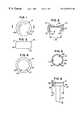
- FIG. 1is a top plan view of a modular head of the preferred embodiment of a modular radial head implant of the present invention.
- FIG. 2is a sectional view substantially as taken on line 2 — 2 of FIG. 1 .
- FIG. 3is side elevational view of the modular head of FIG. 1 .
- FIG. 4is bottom plan view of the modular head of FIG. 1 .
- FIG. 5is a top plan view of a modular body of the preferred embodiment of a modular radial head implant of the present invention.
- FIG. 6is a side elevational view of the modular body of FIG. 5 .
- FIG. 7is a top plan view of a modular head of the preferred embodiment of a modular radial head sizer of the present invention.
- FIG. 8is a sectional view substantially as taken on line 8 — 8 of FIG. 7 .
- FIG. 9is side elevational view of the modular head of FIG. 7 .
- FIG. 10is a sectional view substantially as taken on line 10 — 10 of FIG. 9 .
- FIG. 11is bottom plan view of the modular head of FIG. 7 .
- FIG. 12is a top plan view of a modular body of the preferred embodiment of a modular radial head sizer of the present invention.
- FIG. 13is a sectional view substantially as taken on line 13 — 13 of FIG. 12, on a somewhat enlarged scale.
- FIG. 14is a side elevational view of the modular body of FIG. 12 .
- FIG. 15is a sectional view substantially as taken on line 15 — 15 of FIG. 14 .
- FIG. 16is a top plan view of a preferred embodiment of a modular body sizer insertion instrument of the present invention.
- FIG. 17is a side elevational view of the modular body sizer insertion instrument of FIG. 16 .
- FIG. 18is a plan view of a preferred embodiment of a modular head sizer insertion instrument of the present invention.
- FIG. 19is a top plan view of a preferred embodiment of a modular radial head broach of the present invention.
- FIG. 20is a side elevational view of the modular radial head broach of FIG. 19 .
- FIG. 21is a sectional view substantially as taken on line 21 — 21 of FIG. 20, on a somewhat enlarged scale.
- FIG. 22is an elevational view of a preferred embodiment of a modular radial head radius crank planer of the present invention, with portions thereof broken away to shown internal structure.
- FIG. 23is a plan view of a portion of the radius crank planer substantially as taken on line 23 — 23 of FIG. 22, on a somewhat enlarged scale.
- FIG. 24is an elevational view of a portion of the radius crank planer substantially as taken on line 24 — 24 of FIG. 23, on a somewhat enlarged scale.
- FIG. 25is an elevational view of a preferred embodiment of a modular radial head locking instrument of the present invention, with portions thereof broken away for clarity.
- FIG. 26is a sectional view substantially as taken on line 26 — 26 of FIG. 25 .
- FIG. 27is a sectional view substantially as taken on line 27 — 27 of FIG. 25 .
- FIG. 28is a sectional view of the proximal end of a radius, having a fractured neck.
- FIG. 29is a sectional view similar to FIG. 28, but with the head and a portion of the neck of the proximal end of the radius excised, and showing the head of a modular radial head broach of the present invention being used to prepare the medullary canal of the proximal end of the radius.
- FIG. 30is a sectional view similar to FIG. 29, but showing the medullary canal of the proximal end of the radius prepared for implantation.
- FIG. 31is a sectional view similar to FIG. 30, but showing the stem of the modular body of the modular radial head sizer of the present invention inserted into the medullary canal, and showing the planer portion of the modular radial head radius crank planer of the present invention being slipped onto the stem.
- FIG. 32is a sectional view similar to FIG. 31, but showing the planer portion of the modular radial head radius crank planer fully positioned on the stem of the modular body of the modular radial head sizer.
- FIG. 33is a sectional view substantially as taken on line 33 — 33 of FIG. 32 .
- FIG. 34is a sectional view similar to FIG. 32, but showing the modular radial head radius crank planer removed from the stem, and showing the modular head of the modular radial head sizer screwed onto the modular sizer head insertion tool and being slipped onto the boss of the modular body of the modular radial head sizer.
- FIG. 35is a sectional view similar to FIG. 34, but showing the modular head fully inserted onto the boss, and showing modular head sizer insertion instrument of the present invention engaging the flats of the neck portion of the stem of the modular body of the modular radial head sizer.
- FIG. 36is a sectional view similar to FIG. 35, but showing the modular body sizer insertion instrument and modular head sizer insertion instrument fully mounted on the respective modular body and modular head, and showing the modular body and modular head rotated 90° with respect to one another and locked together.
- FIG. 37is a sectional view substantially as taken on line 37 — 37 of FIG. 35 .
- FIG. 38is a sectional view similar to FIG. 36, but showing the modular body sizer insertion instrument and modular head sizer insertion instrument removed therefrom, and illustrating a trial reduction of the proximal end of the radius and the capitellum of the humerus.
- FIG. 39is a sectional view similar to FIG. 38, but showing the modular radial head sizer removed from the radius, showing the stem of the modular body of the modular radial head implant of the present invention being placed into the medullary canal of the radius, and showing the modular head of the modular radial head implant being placed onto the boss of the modular body thereof.
- FIG. 40is a sectional view similar to FIG. 39 but showing the modular radial head locking instrument of the present invention engaging the modular radial head implant to lock the modular head and modular body thereof together.
- FIG. 41is a sectional view similar to FIG. 40, but with the modular radial head locking instrument removed, with the modular head and modular body locked together, and illustrating a reduction of the proximal end of the radius and the capitellum of the humerus.
- the preferred embodiment of the system of the present inventionis used for replacing or resurfacing the radial head of an elbow joint.
- the system of the present inventioncould be used for other joints, with modifications to accommodate the particular size and anatomical shape and positioning, etc., without changing the essential structure and operation of the system of the present invention.
- the system of the present inventionincludes a modular radial head implant 11 (see, in general, FIGS. 39-41) for replacing the head H of the proximal end P of a radius R in the event the neck N of the proximal end P of the radius R has a fracture F (see, in general, FIG. 28 ), or the head H otherwise needs to be replaced.
- the modular radial head implant 11includes a modular head 13 (see, in general, FIGS. 1-4) and a modular body 15 (see, in general, FIGS. 5 and 6 ).
- the modular bead 13includes a proximal end 17 having a slight concavity 19 therein for articulation with the capitellum C of a humerus (see FIG. 41 ).
- the modular head 13has a distal end 21 and an outer wall 23 extending between the proximal and distal ends 17 , 21 thereof.
- the outer wall 23 of the modular head 13preferably curves outwardly slightly between said proximal and distal ends 17 , 21 thereof as clearly shown in FIGS. 2 and 3 with the modular head 13 forming a circular disc with a barrel-shaped outer wall.
- the modular head 13thus substantially reproduces the anatomical articular geometry of the head H, or proximal end P, of a radius R.
- the modular head 13includes a first lock member 25 .
- the first lock member 25preferably has a cavity 27 with a female taper.
- the sides of the cavity 27preferably taper inwardly from the distal end 21 of the modular head 13 a combined total of approximately 3° as indicated by the arrow 29 in FIG. 2 .
- the modular body 15includes a distal end 31 for engaging the proximal end P of the radius R (see FIGS. 39 - 41 ), and a proximal end 33 .
- the modular body 15includes a second lock member 35 for coacting with the first lock member 25 of the modular head 13 to lock the modular head 13 and the modular body 15 together.
- the distal end 31 of the modular body 15preferably has a elongated stem 37 for extending into the medullary canal MC of the proximal end P of the radius R (see FIGS. 39 - 41 ).
- the proximal end 33 of the modular body 15preferably has an enlarged boss or platform 39 for fitting into the cavity 27 of the first lock member 25 of the modular head 13 .
- the platform 39preferably has a male taper for coacting with the female taper of the cavity 27 of the first lock member 25 of the modular head 13 to lock the modular head 13 and the modular body 15 together.
- the sides of the platform 39preferably taper outwardly from the proximal end 33 of the modular body 15 a combined total of approximately 3° as indicated by the arrow 41 in FIG. 6, and the platform 39 is preferably sized so as to tightly fit into the cavity 27 so that the male and female tapers will securely lock together when the modular head 13 and modular body 15 are forcibly brought together as will now be apparent to those skilled in the art.
- the modular body 15has a drainage passage 43 allowing fluid trapped between the first and second lock members 25 , 33 to drain out.
- the drainage passage 43preferably consists of a hole or aperture 45 extending through the platform 39 from the proximal end 33 of the modular body 15 , through the platform 39 to a point exterior of the stem 37 as clearly shown in FIG. 6 .
- the modular body 15has a plurality of spaced drainage passages 43 through the platform 39 as shown in FIG. 5 .
- the modular head 13 and modular body 15may be constructed in various manners and out of various materials as will now be apparent to those skilled in the art to substantially reproduce anatomical articular geometry.
- the modular head 13 and modular body 15can each be machined or otherwise constructed as a one-piece, integral unit out of a medical grade, physiologically acceptable material such as a cobalt chromium molybdenum alloy or the like, in various sizes to fit a range of typical patients, etc.
- the modular head 13 and modular body 15are preferably highly polished.
- the modular radial head implant 11includes a plurality of different size modular heads 13 and bodies 15 for allowing different size modular radial head implants 11 to be assembled from individual heads 13 and bodies 15 .
- modular heads 13may be provided with 5 different head diameters ranging between 20 and 28 millimeters in 2 millimeter increments, and with 3 different head heights ranging between 9 and 13 millimeters in 2 millimeter increments.
- Modular bodies 15may be provided with 5 different stem diameters ranging between 5.5 and 9.5 millimeters in 1 millimeter increments, and with 3 different stem lengths ranging between 20 and 24 millimeters in 2 millimeter increments.
- the various heads 13 and bodies 15are preferably universally modular, so that all of the bodies 15 will work with all of the heads 13 , and vice versa.
- the system of the present inventionincludes a modular radial head sizer 2 . 11 (see, in general, FIGS. 34-38) for allowing a trial reduction of the elbow joint to help determine the proper size modular radial head implant 11 to use as will now be apparent to those skilled in the art.
- the modular radial head sizer 2 . 11includes a modular head 2 . 13 (see, in general, FIGS. 7-11) and a modular body 2 . 15 (see, in general, FIGS. 12 - 15 ).
- the modular head 2 . 13includes a proximal end 2 . 17 having a slight concavity 2 . 19 therein for articulation with the capitellum C of a humerus (see FIG. 38) during trial reduction of the modular radial head sizer 2 . 11 .
- the modular head 2 . 13has a distal end 2 . 21 and an outer wall 2 . 23 extending between the proximal and distal ends 2 . 17 , 2 . 21 thereof.
- the outer wall 2 . 23 of the modular head 2 . 13preferably curves outwardly slightly between said proximal and distal ends 2 . 17 , 2 . 21 thereof as clearly shown in FIGS. 8-10 with the modular head 2 .
- the modular head 2 . 13forming a circular disc with a barrel-shaped outer wall.
- the modular head 2 . 13thus substantially reproduces the anatomical articular geometry of the head H, or proximal end P, of a radius R.
- the modular head 2 . 13has a cavity 2 . 27 for lockably receiving a portion of the modular body 2 . 15 as will hereinafter become apparent, and has a side entrance opening 2 . 28 to the cavity 2 . 27 through the outer wall 2 . 23 .
- the modular head 2 . 13preferably has a internally threaded aperture or cavity 2 . 29 extending into or through the outer wall 2 . 23 . As indicated in FIGS. 9 and 10, the threaded cavity 2 . 29 may be directly opposite the side entrance opening 2 . 28 .
- the modular body 2 . 15includes a distal end 2 . 31 for engaging the proximal end P of the radius R (see, in general, FIGS. 31, 32 , 34 - 36 and 38 ), and a proximal end 2 . 33 .
- the distal end 2 . 31 of the modular body 2 . 15preferably has a elongated stem 2 . 37 for extending into the medullary canal MC of the proximal end P of the radius R (see FIGS. 31, 32 , 34 - 36 and 38 ).
- the proximal end 2 . 33 of the modular body 2 . 15preferably has an enlarged boss or platform 2 . 39 for fitting into the cavity 2 . 27 of the modular head 2 . 13 .
- the platform 2 . 39is adapted to be inserted through the side entrance opening 2 . 28 of said modular head 2 . 13 into the cavity 2 . 27 of the modular head 2 . 13 .
- the modular radial head sizer 2 . 11preferably includes lock means 2 . 47 (see, in general, FIG. 37) for locking the modular head 2 . 13 and modular body 2 . 15 together after the platform 2 . 39 of the modular body 2 . 15 is inserted into the cavity 2 . 27 of the modular head 2 . 13 through the side entrance opening 2 . 28 of the modular head 2 . 13 .
- the lock means 2 . 47preferably includes ball-and-detent type means for locking the modular head 2 . 13 and modular body 2 . 15 together when the platform 2 . 39 of the modular body 2 . 15 is inserted into the cavity 2 . 27 of the modular head 2 . 13 through the side entrance opening 2 . 28 of the modular head 2 . 13 and rotated.
- the ball-and-detent type meansmay be any typical operation and construction now apparent to those skilled in the art such as a true ball-and-detent lock including a ball-and-spring means 2 . 51 in the opposite ends of the platform 2 . 39 as clearly shown in FIG. 13, and coacting detents or apertures 2 . 53 in the modular head 2 . 13 on opposite sides of the cavity 2 . 27 as clearly shown in FIG. 8 spaced 90° from the side entrance opening 2 . 28 so that the modular head 2 . 13 and modular body 2 . 15 will be locked together when the platform 2 . 39 of the modular body 2 . 15 is inserted into the cavity 2 . 27 of the modular head 2 . 13 through the side entrance opening 2 . 28 of the modular head 2 . 13 and rotated 90° as will now be apparent to those skilled in the art.
- the proximal end or neck 2 . 55 of the stem 2 . 37 immediately adjacent the platform 2 . 39 of the modular body 2 . 15preferably has at least two opposite flats 2 . 57 on the exterior thereof located parallel to the flat sides of the platform 2 . 39 for reasons which will hereinafter become apparent.
- the neck 2 . 55may have three sets of opposite flats 2 . 57 to provide a hexagonal cross section as clearly shown in FIG. 15 .
- the modular head 2 . 13 and modular body 2 . 15may be constructed in various manners and out of various materials as will now be apparent to those skilled in the art to substantially reproduce anatomical articular geometry.
- the modular head 2 . 13 and modular body 2 . 15except for the ball-and-spring means 2 . 51 , can each be machined or otherwise constructed as a one-piece, integral unit out of a medical grade, physiologically acceptable material, in various sizes to fit a range of typical patients, etc.
- the modular radial head sizer 2 . 11includes a plurality of different size modular heads 2 . 13 and bodies 2 . 15 for allowing different size modular radial head sizers 2 . 11 to be assembled from individual heads 2 .
- modular heads 2 . 13may be provided to conform to the modular heads 13 of the modular radial head implants 11 with 5 different head diameters ranging between 20 and 28 millimeters in 2 millimeter increments, and with 3 different head heights ranging between 9 and 13 millimeters in 2 millimeter increments.
- modular bodies 2 . 15may be provided to conform to the modular bodies 15 of the modular radial head implants 11 with 5 different stem diameters ranging between 5.5 and 9.5 millimeters in 1 millimeter increments, and with 3 different stem lengths ranging between 20 and 24 millimeters in 2 millimeter increments.
- the various heads 2 . 13 and bodies 2 . 15are preferably universally modular, so that all of the bodies 2 . 15 will work with all of the heads 2 . 13 , and vice versa.
- the system of the present inventionincludes modular radial head sizer insertion instrumentation for use in inserting the modular radial head sizer 2 . 11 into the elbow joint.
- the instrumentationincluding a modular sizer head insertion tool 3 . 13 and a modular sizer body holding tool 3 . 15 (see, in general, FIGS. 16 - 18 ).
- the modular sizer head insertion tool 3 . 13includes an elongated body 3 . 17 having a first end 3 . 19 and a second end 3 . 21 .
- the first end 3 . 19 of the elongated body 3 . 17 of the modular sizer head insertion tool 3 . 13includes a grip portion 3 . 23 .
- the second end 3 . 21 of the elongated body 3 . 17 of the modular sizer head insertion tool 3 . 13includes a threaded stud 3 . 25 for screwing into the threaded cavity 2 . 29 in the outer wall 2 . 23 of the modular head 2 . 13 of the modular radial head sizer 2 . 11 .
- the modular sizer body holding tool 3 . 15includes an elongated body 3 . 27 having a first end 3 . 29 and a second end 3 . 31 .
- the first end 3 . 29 of the elongated body 3 . 27 of the modular sizer body holding tool 3 . 15includes a grip portion 3 . 33 .
- the second end 3 . 31 of the elongated body 3 . 27 of the modular sizer body holding tool 3 . 15has a mouth 3 . 35 with two opposite and parallel jaws 3 . 37 for engaging the flats 2 . 57 of the neck portion 2 . 55 of the stem 2 . 37 of the modular body 2 . 15 of the modular radial head sizer 2 . 11 to allow the modular sizer body holding tool 3 .
- the elongated body 3 . 27preferably has a double bend 3 . 39 between the first and second ends 3 . 29 , 3 . 31 as clearly shown in FIG. 17 to provide enhanced finger clearance adjacent the grip portion 3 . 33 as will hereinafter become apparent.
- the modular sizer head insertion tool 3 . 13 and modular sizer body holding tool 3 . 15may be constructed in various manners and out of various materials as will now be apparent to those skilled in the art.
- the modular sizer head insertion tool 3 . 13 and modular sizer body holding tool 3 . 15can each be machined or otherwise constructed as a one-piece, integral unit out of a medical grade or the like in various sizes to fit the respective modular head 2 . 13 and modular body 2 . 15 of the modular radial head sizer 2 . 11 .
- the system of the present inventionincludes a modular radial head broach 4 . 11 (see, in general, FIGS. 19-21) for use in preparing the medullary canal MC of the proximal end P of the radius R to receive the proper size modular radial head implant 11 .
- the modular radial head broach 4 . 11includes an elongated body 4 . 13 having a first end 4 . 15 and a second end 4 . 17 .
- the first end 4 . 15 of the elongated body 4 . 13includes a grip portion 4 . 19 , either formed as a part thereof or attached thereto, and especially formed to be hand-gripped.
- the second end 4 . 17 of the elongated body 4 . 13includes a cutting head 4 .
- the elongated body 4 . 13is preferably bent adjacent the cutting head 4 . 21 as indicated by the arrow 4 . 23 in FIG. 20, and the cutting head 4 . 21 is relatively short (shorter than the corresponding implant stem) to allow easy joint access and facilitate introduction into the medullary canal MC.
- the cutting head 4 . 21preferably has a blunt, rounded tip 4 . 25 to protect the capitellum cartilage and prevent soft tissue disruption upon introduction to the joint space.
- gentle cutting teeth 4 . 27are formed on the sides of the cutting head 4 . 21 from longitudinal flats cut on the circumference of the cutting head 4 . 21 , spaced every 30°.
- the modular radial head broach 4 . 11may be constructed in various manners and out of various materials as will now be apparent to those skilled in the art.
- the elongated body 4 . 13 and cutting head 4 . 21can be machined or otherwise constructed as a one-piece, integral unit out of a stainless steel or the like, in various sizes to fit a range of typical patients, etc.
- the grip portion 4 . 19may be machined or otherwise constructed as a separate unit out of Radel polymer or the like and press fitted or otherwise joined to the first end 4 . 15 of the elongated body 4 . 13 .
- the system of the present inventionincludes a series of modular radial head broaches 4 . 11 having different size cutting heads 4 .
- modular radial head broaches 4 . 11may be provided to conform to the modular bodies 15 of the modular radial head implants 11 with 5 different stem diameters ranging between 5.5 and 9.5 millimeters in 1 millimeter increments.
- the system of the present inventionincludes modular radial head radius crank planer 5 . 11 for use in preparing the proximal end P of the radius R to receive the modular radial head implant 11 .
- the modular radial head radius crank planer 5 . 11provides a “bit and brace” style hand-powered instrument to provide central axis loading with off-axis, bi-directional rotation to provide planing action for the resected end of the radius R.
- the modular radial head radius crank planer 5 . 11includes an elongated shaft 5 . 13 having a first end 5 . 15 and a second end 5 . 17 , a handle or knob 5 . 19 for mounting to the first end 5 . 15 of the shaft 5 . 13 , a cutting head 5 .
- the cutting head 5 . 21has an elongated arm 5 . 25 terminating in a cutting or planer portion 5 . 27 .
- the cutting or planer portion 5 . 27is in the form of a flat disk with a plurality of cutting teeth 5 . 29 on one side and a center slot 5 . 31 for mating with the neck portion 2 . 55 of the stem 2 . 37 of the modular body 2 . 15 of a modular radial head sizer 2 . 11 . As shown in FIG.
- the direction of the cutting teeth 5 . 29preferably changes 30° every 60°.
- the profile of the cutting teeth 5 . 29is preferably created from ⁇ fraction (1/16) ⁇ inch (0.15875 centimeter) diameter ball ended slots spaced 0.070 inch (0.1778 centimeter) along the face of the cutting or planer portion 5 . 27 .
- the shaft 5 . 13is off-set as indicated by the arrow 5 . 33 in FIG. 22 so that a longitudinal axis 5 . 35 passing through the handle or knob 5 . 19 will pass through the center of the cutting or planer portion 5 . 27 as clearly indicated in FIG. 22 .
- the modular radial head crank planer 5 . 11may be constructed in various manners and out of various materials as will now be apparent to those skilled in the art.
- the elongated shaft 5 . 13 , handle 5 . 19 and cutting head 5 . 21can be machined or otherwise constructed out of a stainless steel or the like, in various sizes to fit a range of typical patients, etc.
- the grip member 5 . 23may be machined or otherwise constructed as a separate unit out of Radel polymer or the like and rotatably positioned on the shaft 5 . 13 .
- the cutting head 5 . 21is preferably modular for replacement due to wear, etc.
- the system of the present inventionincludes a modular radial head locking instrument 6 . 11 for use in locking a selected modular head 2 . 13 and a selected modular body 2 . 15 of the modular radial head implant 11 .
- the modular radial head locking instrument 6 . 11preferably includes an adapted femoral head extractor instrument 6 . 13 or the like such as the femoral head extractor instrument (No. 5014) manufactured and/or sold by Immedica, Inc. of 871 Mountain Avenue, Springfield, N.J. 07081.
- the locking instrumentincludes a first jaw 6 . 15 , a second jaw 6 . 17 , an elongated body 6 . 19 , and a lever arm 6 . 21 or the like adapted to cause the first and second jaws 6 .
- the first jaw 6 . 15is adapted to engage the underside of the platform 39 of a modular body 15 of the modular radial head implant 11
- the second jaw 6 . 17is adapted to engage the proximal end 17 of a modular head 13 of the modular radial head implant 11 as clearly shown in FIG. 40.
- a soft pad 6 . 23 manufactured out of plastic or the likeis preferably provided on the jaw 6 . 17 to provide a soft interface with the proximal end 17 of the modular head 13 of the implant 11 to prevent implant damage.
- the first jaw 6 . 15preferably has a distal end with a slot 6 .
- the second jaw 6 . 17preferably has a distal end with a modular centering means for receiving and positioning the modular head 15 of the modular implant 11 .
- the modular centering meanspreferably consist of a curved wall 6 . 27 on the pad 6 . 23 to engage and position the proximal end 17 of the modular head 15 of the modular implant 11 .
- the locking instrument 6 . 11thus allows offset axial compression of the modular head 13 and modular body 15 of the implant 11 .
- the instrument 6 . 13may include the typical screw adjustment and force gauge mechanism 6 . 29 .
- the modular radial head locking instrument 6 . 11may be constructed in various manners and out of various materials as will now be apparent to those skilled in the art.
- the working mechanism of the locking instrument 6 . 11preferably consist of an adapted Immedica femoral head extractor.
- the first and second jaws 6 . 15 , 6 . 17can be machined or otherwise constructed out of a stainless steel or the like.
- Several different size pads 6 . 23i.e., pads 6 . 23 with different size curved walls 6 . 27 to correspond to modular heads 15 having different diameters
- the surgical procedure or technique for using the modular radial head system of the present inventioncan vary as will now be apparent to those skilled in the art.
- the preferred surgical techniquepreferably includes the following steps:
- the radial neck Nis resected to the level of the fracture F or to the desired level of radial head resection.
- the annular and collateral ligamentsare preserved where possible.
- an openingis created in the medullary canal MC.
- the appropriate modular radial head broach 4 . 11based on pre-operative templating, is used to further shape the canal MC to receive the stem 2 . 37 of the modular body 2 . 13 of the modular radial head sizer 2 . 11 and the stem 37 of the modular body 15 of the modular radial head implant 11 .
- the stem 2 . 37 of the modular body 2 . 13 of the modular radial head sizer 2 . 11is the inserted into the prepared medullary canal MC, and the cutting head 5 . 21 of the modular radial head crank planer 5 . 11 is slipped over the neck portion 2 . 55 of the stem 2 . 37 , and rotated back and forth around the longitudinal axis 5 . 35 to create a plane surface on the resected end of the proximal end P of the radius R.
- the modular body 2 . 15 of the modular radial head sizer 2 . 11will rotate with the cutting head 5 . 21 of the modular radial head crank planer 5 . 11 .
- Axial forceis applied to the handle 5 . 19 at the top of the crank planer 5 . 11 when the grip member 5 . 23 is moved in an arc about the longitudinal axis 5 . 35 .
- the appropriate modular head 2 . 13 of the modular radial head sizer 2 . 11is screwed onto the threaded stud 3 . 25 of the modular sizer head insertion tool 3 . 13 .
- the mouth 3 . 35 of the grip portion 3 . 33 of the modular sizer body holding tool 3 . 15is placed onto the neck portion 2 . 55 , or keyway, of the stem 2 . 37 of the modular body 2 . 15 of the modular radial head sizer 2 . 11 to hold the modular body 2 . 15 in place as the modular head 2 . 13 of the modular radial head sizer 2 . 11 is slipped onto the platform 2 . 39 of the modular body 2 . 15 .
- the modular sizer body holding tool 3 . 15keeps the modular body 2 . 15 from rotating with respect to the modular head 2 . 13 . Once the modular head 2 . 13 has slipped over the platform 2 . 39 of the modular body 2 . 15 , moving the modular sizer head insertion tool 3 . 13 with respect to the modular sizer body holding tool 3 . 15 causes the modular head 2 . 13 to rotate relative to the modular body 2 . 15 . Once the modular head 2 . 13 has been rotated 90° (or a quarter-turn) relative to the modular body 2 . 15 , the modular head 2 . 13 and modular body 2 . 15 will be locked together via the ball-and-detent means. Unscrew the modular sizer head insertion tool 3 .
- the modular sizer head insertion tool 3 . 13is reattached to the modular head 2 . 13 , and the modular sizer body holding tool 3 . 15 is placed back into the neck portion 2 . 55 , or keyway, of the stem sizer.
- the modular head 2 . 13is unlocked from the modular body 2 . 14 by rotating the modular head 2 . 13 a quarter turn, or 90°, relative to the modular body 2 . 15 again, and the modular head 2 . 13 is removed from the joint space.
- the modular body 2 . 15is then removed from the joint space and the joint thoroughly irrigated.
- the appropriate size of modular body 15is selected and placed into the radial canal MC.
- the appropriate size of modular head 13is selected and prepared for implantation. Using finger control, the modular head 13 is placed into the joint space with the female taper of the cavity 27 of the modular head 13 over the male taper of the platform 39 of the modular body 15 . At this point, the modular head 13 and modular body 15 are not locked together, but are in position to be locked together.
- the appropriate assembly tool head insert 6 . 23is placed onto the second jaw 6 . 17 of the modular radial head locking instrument 6 . 11 .
- the lever arm 6 . 21 of the modular radial head locking instrument 6 . 11is opened out away from the instrument body 6 . 19 .
- the jaws 6 . 15 , 6 . 17 of the locking instrument 6 . 11are adjusted to the approximate head height as denoted by graduations on the shaft, etc.
- the distal ends of the jaws 6 . 15 , 6 . 17are placed into the joint space so that the proximal end 17 of the modular head 13 of the implant 11 is resting on the plastic pad 6 .
- the implant 11 and implant 11 beyond the 2000N forcemay result in breakage of the instrument 6 . 11 or damage to the implant 11 .
- the implant 11may alternatively be assembled in the same manner outside the body.
- the two implant components 13 , 15are placed into the jaws 6 . 15 , 6 . 17 of the locking instrument 6 . 11 , the jaws 6 . 15 , 6 . 17 are tightened onto the implant components 13 , 15 , then the 2000N-assembly load is applied to the two components 13 , 15 by forcing the lever arm 6 . 21 toward the assembly tool body 6 . 19 .
- the locking instrument 6 . 11is removed from the joint space.
- the capsule, ligaments, and the anconeus and extensor carpi ulnaris musclesare sutured in layers with non-absorbable sutures, burying the knots.
- the preferred embodiment of the present inventionprovides:
- (B)a modular radial head sizer in which (1) the stem (body) and head components are modular; (2) the stem (body) and head components are assembled in a side loading manner via a slot and a groove, and rotated slightly to lock together; (3) the stem (body) components have two opposite flats under the platform or boss for coacting with a tool to keep the stem (body) from rotating as the head is rotated for locking; (4) the head component has a screw hole for receiving an insertion instrument to rotate the head component with respect to the stem (body) component to achieve locking; and (5) the head component has a slot that mates with the platform or boss of the stem (body) component, and a retaining groove that the platform (boss) spins in to capture the stem (body) component;
- (F) modular radial head locking componentsfor fitting an adapted femoral head extractor in which: (1) the components allow offset axial compression of the modular radial head components; (2) modular Ultem pieces corresponding to the different stem sizes are interchangeable with the stem locking component; (3) the Ultem pieces provide a soft, elevated pad to compress the stem (body) components into the head components; (4) the head locking components incorporate a thin plastic pad as the implant/instrument interface to prevent implant damage; and (5) both components incorporate an I-beam shape to provide increased resistance to deflection under load.
Landscapes
- Health & Medical Sciences (AREA)
- Orthopedic Medicine & Surgery (AREA)
- Transplantation (AREA)
- Heart & Thoracic Surgery (AREA)
- Cardiology (AREA)
- Oral & Maxillofacial Surgery (AREA)
- Engineering & Computer Science (AREA)
- Biomedical Technology (AREA)
- Physical Education & Sports Medicine (AREA)
- Vascular Medicine (AREA)
- Life Sciences & Earth Sciences (AREA)
- Animal Behavior & Ethology (AREA)
- General Health & Medical Sciences (AREA)
- Public Health (AREA)
- Veterinary Medicine (AREA)
- Prostheses (AREA)
Abstract
Description
Claims (4)
Priority Applications (9)
| Application Number | Priority Date | Filing Date | Title |
|---|---|---|---|
| US09/388,093US6270529B1 (en) | 1999-09-01 | 1999-09-01 | Modular implant for replacing end of radius and having drainage passage for trapped fluid |
| CA002314863ACA2314863C (en) | 1999-09-01 | 2000-08-02 | Radial head implant system including modular implants, sizers and instrumentation |
| EP09150427AEP2078511B1 (en) | 1999-09-01 | 2000-08-03 | Modular head system for replacing the head of the proximal end of a radius |
| EP00250260AEP1080701B1 (en) | 1999-09-01 | 2000-08-03 | Radial head implant |
| EP06118224AEP1772118B1 (en) | 1999-09-01 | 2000-08-03 | Modular head system for replacing the head of the proximal end of a radius |
| DE60042351TDE60042351D1 (en) | 1999-09-01 | 2000-08-03 | Modular head system for replacing the proximal radial head. |
| DE60045087TDE60045087D1 (en) | 1999-09-01 | 2000-08-03 | Modular head system for replacing the head of the proximal end of a spoke |
| DE60029702TDE60029702T2 (en) | 1999-09-01 | 2000-08-03 | Implant for a spinal head |
| US09/854,958US6361563B2 (en) | 1999-09-01 | 2001-05-15 | Radial head implant system including modular implant and modular radial head locking instrument |
Applications Claiming Priority (1)
| Application Number | Priority Date | Filing Date | Title |
|---|---|---|---|
| US09/388,093US6270529B1 (en) | 1999-09-01 | 1999-09-01 | Modular implant for replacing end of radius and having drainage passage for trapped fluid |
Related Child Applications (1)
| Application Number | Title | Priority Date | Filing Date |
|---|---|---|---|
| US09/854,958DivisionUS6361563B2 (en) | 1999-09-01 | 2001-05-15 | Radial head implant system including modular implant and modular radial head locking instrument |
Publications (1)
| Publication Number | Publication Date |
|---|---|
| US6270529B1true US6270529B1 (en) | 2001-08-07 |
Family
ID=23532659
Family Applications (2)
| Application Number | Title | Priority Date | Filing Date |
|---|---|---|---|
| US09/388,093Expired - LifetimeUS6270529B1 (en) | 1999-09-01 | 1999-09-01 | Modular implant for replacing end of radius and having drainage passage for trapped fluid |
| US09/854,958Expired - LifetimeUS6361563B2 (en) | 1999-09-01 | 2001-05-15 | Radial head implant system including modular implant and modular radial head locking instrument |
Family Applications After (1)
| Application Number | Title | Priority Date | Filing Date |
|---|---|---|---|
| US09/854,958Expired - LifetimeUS6361563B2 (en) | 1999-09-01 | 2001-05-15 | Radial head implant system including modular implant and modular radial head locking instrument |
Country Status (4)
| Country | Link |
|---|---|
| US (2) | US6270529B1 (en) |
| EP (3) | EP2078511B1 (en) |
| CA (1) | CA2314863C (en) |
| DE (3) | DE60045087D1 (en) |
Cited By (90)
| Publication number | Priority date | Publication date | Assignee | Title |
|---|---|---|---|---|
| US6361563B2 (en)* | 1999-09-01 | 2002-03-26 | Wright Medical Technology, Inc. | Radial head implant system including modular implant and modular radial head locking instrument |
| US6709459B1 (en)* | 2000-08-31 | 2004-03-23 | Mayo Foundation For Medical Education And Research | Radial implant system |
| US20040186580A1 (en)* | 2003-01-30 | 2004-09-23 | Steinmann Scott P. | Radial head replacement system |
| US20050049710A1 (en)* | 2003-08-28 | 2005-03-03 | O'driscoll Shawn W. | Prosthesis for partial replacement of an articulating surface on bone |
| US20050216090A1 (en)* | 2004-03-11 | 2005-09-29 | O'driscoll Shawn W | Systems for bone replacement |
| US20060064173A1 (en)* | 2004-09-08 | 2006-03-23 | Arthrex, Inc. | Modular system for replacement of radial head |
| US20060116771A1 (en)* | 2004-12-01 | 2006-06-01 | Cooney William P Iii | Radial-capitellar implant |
| US20060142866A1 (en)* | 2004-08-23 | 2006-06-29 | Mark Baratz | Radial head implant apparatuses and methods |
| US20070055240A1 (en)* | 2005-07-08 | 2007-03-08 | Wilfried Matthis | Bone anchoring device |
| US20080288079A1 (en)* | 2007-02-10 | 2008-11-20 | Small Bone Innovations, Inc. | Radial Head Implant and Related Instrument |
| US20100137918A1 (en)* | 2008-12-03 | 2010-06-03 | Warsaw Orthopedic, Inc. | Rod and anchor system and method for using |
| US20100234846A1 (en)* | 2009-03-13 | 2010-09-16 | Eglseder W Andrew | Intramedullary radial head locking pin implant |
| US20110035016A1 (en)* | 2009-08-06 | 2011-02-10 | Skeletal Dynamics, Llc | Alignable prostheses device, system and method |
| US8110005B2 (en) | 2000-04-10 | 2012-02-07 | Biomet Manufacturing Corp. | Modular prosthesis and use thereof for replacing a radial head |
| US8535382B2 (en) | 2000-04-10 | 2013-09-17 | Biomet Manufacturing, Llc | Modular radial head prostheses |
| US8764760B2 (en) | 2011-07-01 | 2014-07-01 | Biomet Manufacturing, Llc | Patient-specific bone-cutting guidance instruments and methods |
| US8828087B2 (en) | 2006-02-27 | 2014-09-09 | Biomet Manufacturing, Llc | Patient-specific high tibia osteotomy |
| US8858561B2 (en) | 2006-06-09 | 2014-10-14 | Blomet Manufacturing, LLC | Patient-specific alignment guide |
| US8864769B2 (en) | 2006-02-27 | 2014-10-21 | Biomet Manufacturing, Llc | Alignment guides with patient-specific anchoring elements |
| US8903530B2 (en) | 2011-06-06 | 2014-12-02 | Biomet Manufacturing, Llc | Pre-operative planning and manufacturing method for orthopedic procedure |
| US8900244B2 (en) | 2006-02-27 | 2014-12-02 | Biomet Manufacturing, Llc | Patient-specific acetabular guide and method |
| US8920509B2 (en) | 2000-04-10 | 2014-12-30 | Biomet Manufacturing, Llc | Modular radial head prosthesis |
| US8956364B2 (en) | 2011-04-29 | 2015-02-17 | Biomet Manufacturing, Llc | Patient-specific partial knee guides and other instruments |
| US8979936B2 (en) | 2006-06-09 | 2015-03-17 | Biomet Manufacturing, Llc | Patient-modified implant |
| US9005297B2 (en) | 2006-02-27 | 2015-04-14 | Biomet Manufacturing, Llc | Patient-specific elbow guides and associated methods |
| WO2015081311A1 (en)* | 2013-11-26 | 2015-06-04 | Nexus Spine, L.L.C. | Surgical tool for a pedicle screw |
| US9060788B2 (en) | 2012-12-11 | 2015-06-23 | Biomet Manufacturing, Llc | Patient-specific acetabular guide for anterior approach |
| US9066734B2 (en) | 2011-08-31 | 2015-06-30 | Biomet Manufacturing, Llc | Patient-specific sacroiliac guides and associated methods |
| US9084618B2 (en) | 2011-06-13 | 2015-07-21 | Biomet Manufacturing, Llc | Drill guides for confirming alignment of patient-specific alignment guides |
| US9113971B2 (en) | 2006-02-27 | 2015-08-25 | Biomet Manufacturing, Llc | Femoral acetabular impingement guide |
| US9155626B2 (en) | 2012-09-10 | 2015-10-13 | Acumed Llc | Radial head prosthesis with floating articular member |
| US9173661B2 (en) | 2006-02-27 | 2015-11-03 | Biomet Manufacturing, Llc | Patient specific alignment guide with cutting surface and laser indicator |
| US9204977B2 (en) | 2012-12-11 | 2015-12-08 | Biomet Manufacturing, Llc | Patient-specific acetabular guide for anterior approach |
| US9237950B2 (en) | 2012-02-02 | 2016-01-19 | Biomet Manufacturing, Llc | Implant with patient-specific porous structure |
| US9241745B2 (en) | 2011-03-07 | 2016-01-26 | Biomet Manufacturing, Llc | Patient-specific femoral version guide |
| US9271744B2 (en) | 2010-09-29 | 2016-03-01 | Biomet Manufacturing, Llc | Patient-specific guide for partial acetabular socket replacement |
| US9289253B2 (en) | 2006-02-27 | 2016-03-22 | Biomet Manufacturing, Llc | Patient-specific shoulder guide |
| US9295497B2 (en) | 2011-08-31 | 2016-03-29 | Biomet Manufacturing, Llc | Patient-specific sacroiliac and pedicle guides |
| US9301812B2 (en) | 2011-10-27 | 2016-04-05 | Biomet Manufacturing, Llc | Methods for patient-specific shoulder arthroplasty |
| US9339278B2 (en) | 2006-02-27 | 2016-05-17 | Biomet Manufacturing, Llc | Patient-specific acetabular guides and associated instruments |
| US9345548B2 (en) | 2006-02-27 | 2016-05-24 | Biomet Manufacturing, Llc | Patient-specific pre-operative planning |
| US9351743B2 (en) | 2011-10-27 | 2016-05-31 | Biomet Manufacturing, Llc | Patient-specific glenoid guides |
| US20160175115A1 (en)* | 2014-12-17 | 2016-06-23 | Integra Lifesciences Corporation | Orthopedic implant sizing instruments, systems, and methods |
| US9386993B2 (en) | 2011-09-29 | 2016-07-12 | Biomet Manufacturing, Llc | Patient-specific femoroacetabular impingement instruments and methods |
| US9393028B2 (en) | 2009-08-13 | 2016-07-19 | Biomet Manufacturing, Llc | Device for the resection of bones, method for producing such a device, endoprosthesis suited for this purpose and method for producing such an endoprosthesis |
| US9408616B2 (en) | 2014-05-12 | 2016-08-09 | Biomet Manufacturing, Llc | Humeral cut guide |
| US9427320B2 (en) | 2011-08-04 | 2016-08-30 | Biomet Manufacturing, Llc | Patient-specific pelvic implants for acetabular reconstruction |
| US9445907B2 (en) | 2011-03-07 | 2016-09-20 | Biomet Manufacturing, Llc | Patient-specific tools and implants |
| US9451973B2 (en) | 2011-10-27 | 2016-09-27 | Biomet Manufacturing, Llc | Patient specific glenoid guide |
| US9456833B2 (en) | 2010-02-26 | 2016-10-04 | Biomet Sports Medicine, Llc | Patient-specific osteotomy devices and methods |
| US9474539B2 (en) | 2011-04-29 | 2016-10-25 | Biomet Manufacturing, Llc | Patient-specific convertible guides |
| US9480490B2 (en) | 2006-02-27 | 2016-11-01 | Biomet Manufacturing, Llc | Patient-specific guides |
| US9480580B2 (en) | 2006-02-27 | 2016-11-01 | Biomet Manufacturing, Llc | Patient-specific acetabular alignment guides |
| US9498233B2 (en) | 2013-03-13 | 2016-11-22 | Biomet Manufacturing, Llc. | Universal acetabular guide and associated hardware |
| US9517145B2 (en) | 2013-03-15 | 2016-12-13 | Biomet Manufacturing, Llc | Guide alignment system and method |
| US9522010B2 (en) | 2006-02-27 | 2016-12-20 | Biomet Manufacturing, Llc | Patient-specific orthopedic instruments |
| US9554910B2 (en) | 2011-10-27 | 2017-01-31 | Biomet Manufacturing, Llc | Patient-specific glenoid guide and implants |
| US9561040B2 (en) | 2014-06-03 | 2017-02-07 | Biomet Manufacturing, Llc | Patient-specific glenoid depth control |
| US9572590B2 (en) | 2006-10-03 | 2017-02-21 | Biomet Uk Limited | Surgical instrument |
| US9579107B2 (en) | 2013-03-12 | 2017-02-28 | Biomet Manufacturing, Llc | Multi-point fit for patient specific guide |
| US9662127B2 (en) | 2006-02-27 | 2017-05-30 | Biomet Manufacturing, Llc | Patient-specific acetabular guides and associated instruments |
| US9662216B2 (en) | 2006-02-27 | 2017-05-30 | Biomet Manufacturing, Llc | Patient-specific hip joint devices |
| US9717510B2 (en) | 2011-04-15 | 2017-08-01 | Biomet Manufacturing, Llc | Patient-specific numerically controlled instrument |
| US9763792B2 (en)* | 2015-10-01 | 2017-09-19 | Acumed Llc | Radial head prosthesis with rotate-to-lock interface |
| US9795399B2 (en) | 2006-06-09 | 2017-10-24 | Biomet Manufacturing, Llc | Patient-specific knee alignment guide and associated method |
| US9820868B2 (en) | 2015-03-30 | 2017-11-21 | Biomet Manufacturing, Llc | Method and apparatus for a pin apparatus |
| US9826981B2 (en) | 2013-03-13 | 2017-11-28 | Biomet Manufacturing, Llc | Tangential fit of patient-specific guides |
| US9826994B2 (en) | 2014-09-29 | 2017-11-28 | Biomet Manufacturing, Llc | Adjustable glenoid pin insertion guide |
| US9833245B2 (en) | 2014-09-29 | 2017-12-05 | Biomet Sports Medicine, Llc | Tibial tubercule osteotomy |
| US9839438B2 (en) | 2013-03-11 | 2017-12-12 | Biomet Manufacturing, Llc | Patient-specific glenoid guide with a reusable guide holder |
| US9839436B2 (en) | 2014-06-03 | 2017-12-12 | Biomet Manufacturing, Llc | Patient-specific glenoid depth control |
| US9861387B2 (en) | 2006-06-09 | 2018-01-09 | Biomet Manufacturing, Llc | Patient-specific knee alignment guide and associated method |
| US9901452B2 (en) | 2013-03-14 | 2018-02-27 | Imds Corporation | Radial head implant |
| US9907659B2 (en) | 2007-04-17 | 2018-03-06 | Biomet Manufacturing, Llc | Method and apparatus for manufacturing an implant |
| US9918740B2 (en) | 2006-02-27 | 2018-03-20 | Biomet Manufacturing, Llc | Backup surgical instrument system and method |
| US9968376B2 (en) | 2010-11-29 | 2018-05-15 | Biomet Manufacturing, Llc | Patient-specific orthopedic instruments |
| US10159498B2 (en) | 2008-04-16 | 2018-12-25 | Biomet Manufacturing, Llc | Method and apparatus for manufacturing an implant |
| US10226262B2 (en) | 2015-06-25 | 2019-03-12 | Biomet Manufacturing, Llc | Patient-specific humeral guide designs |
| US10282488B2 (en) | 2014-04-25 | 2019-05-07 | Biomet Manufacturing, Llc | HTO guide with optional guided ACL/PCL tunnels |
| US10278711B2 (en) | 2006-02-27 | 2019-05-07 | Biomet Manufacturing, Llc | Patient-specific femoral guide |
| US10357372B2 (en) | 2013-03-28 | 2019-07-23 | Mayo Foundation For Medical Education And Research | Radial head trials |
| US10478313B1 (en) | 2014-01-10 | 2019-11-19 | Nuvasive, Inc. | Spinal fusion implant and related methods |
| US10492798B2 (en) | 2011-07-01 | 2019-12-03 | Biomet Manufacturing, Llc | Backup kit for a patient-specific arthroplasty kit assembly |
| US10568647B2 (en) | 2015-06-25 | 2020-02-25 | Biomet Manufacturing, Llc | Patient-specific humeral guide designs |
| US10603179B2 (en) | 2006-02-27 | 2020-03-31 | Biomet Manufacturing, Llc | Patient-specific augments |
| US10722310B2 (en) | 2017-03-13 | 2020-07-28 | Zimmer Biomet CMF and Thoracic, LLC | Virtual surgery planning system and method |
| US20210290401A1 (en)* | 2020-03-18 | 2021-09-23 | In2Bones Usa, Llc | Radial head fracture treatment system |
| US11179165B2 (en) | 2013-10-21 | 2021-11-23 | Biomet Manufacturing, Llc | Ligament guide registration |
| US20210369465A1 (en)* | 2020-05-26 | 2021-12-02 | Howmedica Osteonics Corp. | Orthopedic surgical implant device with porous material and fluid channels for cleaning the porous material |
| US11419618B2 (en) | 2011-10-27 | 2022-08-23 | Biomet Manufacturing, Llc | Patient-specific glenoid guides |
Families Citing this family (42)
| Publication number | Priority date | Publication date | Assignee | Title |
|---|---|---|---|---|
| US6027534A (en)* | 1997-11-03 | 2000-02-22 | Deputy Orthopaedics, Inc. | Modular elbow |
| WO2003094700A2 (en)* | 2002-05-09 | 2003-11-20 | Hayes Medical, Inc. | Method and instruments for inserting modular implant components |
| FR2840039B1 (en) | 2002-05-22 | 2004-11-12 | Bioprofile | CONICAL COUPLING AND PROSTHESIS COMPRISING SUCH A COUPLING |
| US7273499B2 (en)* | 2002-09-30 | 2007-09-25 | Depuy Products, Inc. | Modular trial mechanism |
| US7235106B2 (en)* | 2002-12-20 | 2007-06-26 | Depuy Products, Inc. | Modular hip stems and associated method of trialing |
| US7854737B2 (en)* | 2002-12-20 | 2010-12-21 | Depuy Products, Inc. | Instrument and associated method of trailing for modular hip stems |
| US7022141B2 (en)* | 2002-12-20 | 2006-04-04 | Depuy Products, Inc. | Alignment device for modular implants and method |
| US20040267267A1 (en)* | 2003-06-25 | 2004-12-30 | Daniels David Wayne | Non-linear reamer for bone preparation and associated method |
| US7297166B2 (en)* | 2003-06-25 | 2007-11-20 | Depuy Products, Inc. | Assembly tool for modular implants and associated method |
| US7582092B2 (en) | 2003-06-25 | 2009-09-01 | Depuy Products, Inc. | Assembly tool for modular implants and associated method |
| US8998919B2 (en) | 2003-06-25 | 2015-04-07 | DePuy Synthes Products, LLC | Assembly tool for modular implants, kit and associated method |
| US7074224B2 (en) | 2003-06-25 | 2006-07-11 | Depuy Products, Inc. | Modular tapered reamer for bone preparation and associated method |
| US7815644B2 (en)* | 2003-12-19 | 2010-10-19 | Masini Michael A | Instrumentation and methods for refining image-guided and navigation-based surgical procedures |
| US7785328B2 (en)* | 2003-12-30 | 2010-08-31 | Depuy Products, Inc. | Minimally invasive bone miller apparatus |
| US8353965B2 (en)* | 2004-09-03 | 2013-01-15 | Seitz Jr William H | Small joint orthopedic implants and their manufacture |
| US7458989B2 (en)* | 2005-06-30 | 2008-12-02 | University Of Florida Rearch Foundation, Inc. | Intraoperative joint force measuring device, system and method |
| US7819924B2 (en)* | 2005-11-14 | 2010-10-26 | Ascension Orthopedics, Inc. | Distal radioulnar joint prosthesis |
| US8597298B2 (en) | 2006-09-29 | 2013-12-03 | DePuy Synthes Products, LLC | Proximal reamer |
| US8556912B2 (en) | 2007-10-30 | 2013-10-15 | DePuy Synthes Products, LLC | Taper disengagement tool |
| US8518050B2 (en) | 2007-10-31 | 2013-08-27 | DePuy Synthes Products, LLC | Modular taper assembly device |
| US20090112219A1 (en)* | 2007-10-31 | 2009-04-30 | Daniels David W | Taper sleeve extractor |
| RU2362516C1 (en)* | 2008-02-13 | 2009-07-27 | Общество с ограниченной ответственностью "ОСТЕОМЕД-М" (ООО "ОСТЕОМЕД-М") | Radius head implant |
| US8167882B2 (en)* | 2008-09-30 | 2012-05-01 | Depuy Products, Inc. | Minimally invasive bone miller apparatus |
| US8968411B2 (en)* | 2009-12-17 | 2015-03-03 | Zimmer, Inc. | Modular elbow prosthesis |
| US8533921B2 (en) | 2010-06-15 | 2013-09-17 | DePuy Synthes Products, LLC | Spiral assembly tool |
| US9095452B2 (en) | 2010-09-01 | 2015-08-04 | DePuy Synthes Products, Inc. | Disassembly tool |
| ES2635496T3 (en) | 2011-04-06 | 2017-10-04 | Depuy Synthes Products Llc | Modular Orthopedic Hip Prosthesis |
| US8696623B2 (en)* | 2011-11-16 | 2014-04-15 | Mgs Mfg. Group, Inc. | Injection molded adjustable shape abscess irrigation device |
| US8936647B2 (en) | 2012-06-22 | 2015-01-20 | Zimmer, Inc. | Elbow prosthesis |
| US10201374B2 (en) | 2012-06-22 | 2019-02-12 | Zimmer, Inc. | Assembly tool for a prosthesis |
| US9510956B2 (en)* | 2012-11-06 | 2016-12-06 | Biomet Manufacturing, Llc | Prosthetic system |
| US9937048B2 (en) | 2015-01-15 | 2018-04-10 | Depuy Ireland Unlimited Company | Femoral stem including an anchor to facilitate assembly and implantation |
| US10085838B2 (en)* | 2015-01-15 | 2018-10-02 | Depuy Ireland Unlimited Company | Assembly tool |
| GB201514727D0 (en) | 2015-08-19 | 2015-09-30 | Depuy Ireland | An Assembly Tool |
| CN110913804B (en) | 2017-04-04 | 2022-03-15 | 托尼尔公司 | Elbow joint prosthesis |
| DE102017126618A1 (en)* | 2017-11-13 | 2019-05-16 | Ot Medizintechnik Gmbh | Radial head implant |
| CN108143521B (en)* | 2017-12-12 | 2019-11-12 | 常州大学 | Humanoid humeroradial joint in elbow joint |
| CN108175541B (en)* | 2018-01-29 | 2024-10-01 | 上海康定医疗器械有限公司 | Distal ulna forearm rotary prosthesis |
| RU184582U1 (en)* | 2018-04-11 | 2018-10-31 | Общество с ограниченной ответственностью "Мойе Керамик-Имплантате" | PROSTHESIS OF THE PROXIMAL BEAM HEAD |
| KR20210086640A (en) | 2018-10-03 | 2021-07-08 | 토르니에, 인코포레이티드 | elbow joint prosthesis |
| JP7270063B2 (en)* | 2019-05-14 | 2023-05-09 | ローサイ・オーソペディックス・リミテッド | A set of tools for introducing implants |
| US11207197B2 (en) | 2019-08-01 | 2021-12-28 | DePuy Synthes Products, Inc. | Orthopaedic surgical instrument for total hip arthroplasty and associated orthopaedic surgical method of use |
Citations (8)
| Publication number | Priority date | Publication date | Assignee | Title |
|---|---|---|---|---|
| US3739403A (en)* | 1970-10-09 | 1973-06-19 | F Nicolle | Prosthetic joint having a tissue ingrowth preventive capsule |
| US4242758A (en) | 1977-06-01 | 1981-01-06 | University Of Leeds Industrial Service Ltd. | Elbow prosthesis |
| US5030237A (en) | 1983-06-24 | 1991-07-09 | Queen's University At Kingston | Elbow prosthesis |
| US5728161A (en)* | 1995-06-08 | 1998-03-17 | Depuy Orthopedics, Inc. | Large taper modular shoulder prosthesis |
| US5769093A (en)* | 1994-12-09 | 1998-06-23 | Xomed Surgical Products, Inc. | Method of relieving synovial fluid pressure |
| US5782922A (en) | 1997-02-07 | 1998-07-21 | Biomet, Inc. | Method and apparatus for replacing the capitellum |
| US5879395A (en) | 1997-01-23 | 1999-03-09 | Tornier Sa | Total elbow prosthesis |
| US5885297A (en) | 1996-06-21 | 1999-03-23 | Matsen, Iii; Frederick A. | Joint replacement method and apparatus |
Family Cites Families (14)
| Publication number | Priority date | Publication date | Assignee | Title |
|---|---|---|---|---|
| US460155A (en)* | 1891-09-29 | Wrench | ||
| GB2022422B (en)* | 1978-05-31 | 1983-01-12 | Wadsworth T G | Elbow replacement prosthesis |
| US4457306A (en)* | 1982-05-05 | 1984-07-03 | Howmedica, Inc. | Tool and method for engaging two members of a joint prosthesis |
| DE3470456D1 (en)* | 1983-06-24 | 1988-05-26 | Univ Kingston | Apparatus for locating an elbow prothesis |
| US4624250A (en)* | 1983-06-24 | 1986-11-25 | Queen's University At Kingston | Instrument for elbow surface replacement arthroplasty |
| US4706660A (en)* | 1985-05-30 | 1987-11-17 | Petersen Thomas D | Patellar clamp |
| DE3808877A1 (en)* | 1988-03-17 | 1989-09-28 | Hermann Dausch | Microsurgical instrument |
| FR2662838B1 (en) | 1990-06-01 | 1994-05-06 | Thomson Csf | WIDE ANGLE DISPLAY DEVICE FOR LOW - SIZE SIMULATOR. |
| FR2663838A1 (en)* | 1990-06-29 | 1992-01-03 | Michel Jean Pierre | Implant for an arthroplasty, in particular of a glenoid cavity |
| EP0558203A1 (en)* | 1992-02-20 | 1993-09-01 | Wright Medical Technology, Inc. | Modular trial instrument with interlock mechanism |
| US5284487A (en)* | 1992-07-31 | 1994-02-08 | Hartmeister Ruben J | Surgical compression forceps |
| DE4331282A1 (en) | 1993-09-15 | 1995-03-16 | Hahn Michael | Joint endoprosthesis |
| US5733333A (en)* | 1996-09-16 | 1998-03-31 | Sankey; Gregory | Artificial eye |
| US6270529B1 (en)* | 1999-09-01 | 2001-08-07 | Wright Medical Technology, Inc. | Modular implant for replacing end of radius and having drainage passage for trapped fluid |
- 1999
- 1999-09-01USUS09/388,093patent/US6270529B1/ennot_activeExpired - Lifetime
- 2000
- 2000-08-02CACA002314863Apatent/CA2314863C/ennot_activeExpired - Lifetime
- 2000-08-03DEDE60045087Tpatent/DE60045087D1/ennot_activeExpired - Lifetime
- 2000-08-03DEDE60042351Tpatent/DE60042351D1/ennot_activeExpired - Lifetime
- 2000-08-03EPEP09150427Apatent/EP2078511B1/ennot_activeExpired - Lifetime
- 2000-08-03EPEP00250260Apatent/EP1080701B1/ennot_activeExpired - Lifetime
- 2000-08-03DEDE60029702Tpatent/DE60029702T2/ennot_activeExpired - Lifetime
- 2000-08-03EPEP06118224Apatent/EP1772118B1/ennot_activeExpired - Lifetime
- 2001
- 2001-05-15USUS09/854,958patent/US6361563B2/ennot_activeExpired - Lifetime
Patent Citations (8)
| Publication number | Priority date | Publication date | Assignee | Title |
|---|---|---|---|---|
| US3739403A (en)* | 1970-10-09 | 1973-06-19 | F Nicolle | Prosthetic joint having a tissue ingrowth preventive capsule |
| US4242758A (en) | 1977-06-01 | 1981-01-06 | University Of Leeds Industrial Service Ltd. | Elbow prosthesis |
| US5030237A (en) | 1983-06-24 | 1991-07-09 | Queen's University At Kingston | Elbow prosthesis |
| US5769093A (en)* | 1994-12-09 | 1998-06-23 | Xomed Surgical Products, Inc. | Method of relieving synovial fluid pressure |
| US5728161A (en)* | 1995-06-08 | 1998-03-17 | Depuy Orthopedics, Inc. | Large taper modular shoulder prosthesis |
| US5885297A (en) | 1996-06-21 | 1999-03-23 | Matsen, Iii; Frederick A. | Joint replacement method and apparatus |
| US5879395A (en) | 1997-01-23 | 1999-03-09 | Tornier Sa | Total elbow prosthesis |
| US5782922A (en) | 1997-02-07 | 1998-07-21 | Biomet, Inc. | Method and apparatus for replacing the capitellum |
Non-Patent Citations (4)
| Title |
|---|
| "Swanson Titanium Radial Head Implant, regular and narrow stem" (C) 1995, Wright Medical Technology, Inc. |
| "The Sorbie-Questor(R) Total Elbow System", (C)1996, Wright Medical Technology, Inc. |
| "Swanson Titanium Radial Head Implant, regular and narrow stem" © 1995, Wright Medical Technology, Inc. |
| "The Sorbie-Questor® Total Elbow System", ©1996, Wright Medical Technology, Inc. |
Cited By (171)
| Publication number | Priority date | Publication date | Assignee | Title |
|---|---|---|---|---|
| US6361563B2 (en)* | 1999-09-01 | 2002-03-26 | Wright Medical Technology, Inc. | Radial head implant system including modular implant and modular radial head locking instrument |
| US8425615B2 (en) | 2000-04-10 | 2013-04-23 | Biomet Manufacturing Corp. | Method and apparatus for adjusting height and angle for a radial head |
| US8366781B2 (en) | 2000-04-10 | 2013-02-05 | Biomet Manufacturing Corp. | Modular prosthesis and use thereof for replacing a radial head |
| US8114163B2 (en) | 2000-04-10 | 2012-02-14 | Biomet Manufacturing Corp. | Method and apparatus for adjusting height and angle for a radial head |
| US9333084B2 (en) | 2000-04-10 | 2016-05-10 | Biomet Manufacturing, Llc | Modular prosthesis and use thereof for replacing a radial head |
| US9439784B2 (en) | 2000-04-10 | 2016-09-13 | Biomet Manufacturing, Llc | Modular radial head prosthesis |
| US20150073561A1 (en)* | 2000-04-10 | 2015-03-12 | Biomet Manufacturing, Llc | Modular radial head prosthesis |
| US9579208B2 (en)* | 2000-04-10 | 2017-02-28 | Biomet Manufacturing, Llc | Modular radial head prosthesis |
| US8920509B2 (en) | 2000-04-10 | 2014-12-30 | Biomet Manufacturing, Llc | Modular radial head prosthesis |
| US8535382B2 (en) | 2000-04-10 | 2013-09-17 | Biomet Manufacturing, Llc | Modular radial head prostheses |
| US8110005B2 (en) | 2000-04-10 | 2012-02-07 | Biomet Manufacturing Corp. | Modular prosthesis and use thereof for replacing a radial head |
| US6709459B1 (en)* | 2000-08-31 | 2004-03-23 | Mayo Foundation For Medical Education And Research | Radial implant system |
| US20040186580A1 (en)* | 2003-01-30 | 2004-09-23 | Steinmann Scott P. | Radial head replacement system |
| US7452381B2 (en) | 2003-01-30 | 2008-11-18 | Mayo Foundation For Medical Education And Research | Radial head replacement system |
| US20090036991A1 (en)* | 2003-01-30 | 2009-02-05 | Steinmann Scott P | Radial Head Replacement System |
| US20050049710A1 (en)* | 2003-08-28 | 2005-03-03 | O'driscoll Shawn W. | Prosthesis for partial replacement of an articulating surface on bone |
| US7608110B2 (en) | 2004-03-11 | 2009-10-27 | O'driscoll Shawn W | Systems for bone replacement |
| US20050216090A1 (en)* | 2004-03-11 | 2005-09-29 | O'driscoll Shawn W | Systems for bone replacement |
| US20060142866A1 (en)* | 2004-08-23 | 2006-06-29 | Mark Baratz | Radial head implant apparatuses and methods |
| US7740661B2 (en)* | 2004-08-23 | 2010-06-22 | Integra Lifesciences Corporation | Radial head implant apparatuses and methods |
| US7641695B2 (en)* | 2004-09-08 | 2010-01-05 | Arthrex, Inc. | Modular system for replacement of radial head |
| US20060064173A1 (en)* | 2004-09-08 | 2006-03-23 | Arthrex, Inc. | Modular system for replacement of radial head |
| US7160329B2 (en) | 2004-12-01 | 2007-01-09 | Mayo Foundation For Medical Research And Education | Radial-capitellar implant |
| US9655726B2 (en) | 2004-12-01 | 2017-05-23 | Mayo Foundation For Medical Research And Education | Radial-capitellar implant |
| US20070073409A1 (en)* | 2004-12-01 | 2007-03-29 | Mayo Foundation For Medical Research And Education | Radial-capitellar implant |
| US20060116771A1 (en)* | 2004-12-01 | 2006-06-01 | Cooney William P Iii | Radial-capitellar implant |
| US8034089B2 (en)* | 2005-07-08 | 2011-10-11 | Biedermann Motech Gmbh | Bone anchoring device |
| US20120143264A1 (en)* | 2005-07-08 | 2012-06-07 | Biedermann Motech Gmbh | Bone anchoring device |
| US20090326587A1 (en)* | 2005-07-08 | 2009-12-31 | Biedermann Motech Gmbh | Bone anchoring device |
| US20070055240A1 (en)* | 2005-07-08 | 2007-03-08 | Wilfried Matthis | Bone anchoring device |
| US8591558B2 (en)* | 2005-07-08 | 2013-11-26 | Biedermann Technologies Gmbh & Co. Kg | Bone anchoring device |
| US9034021B2 (en)* | 2005-07-08 | 2015-05-19 | Biedermann Technologies Gmbh & Co. Kg | Bone anchoring device |
| US10743937B2 (en) | 2006-02-27 | 2020-08-18 | Biomet Manufacturing, Llc | Backup surgical instrument system and method |
| US9700329B2 (en) | 2006-02-27 | 2017-07-11 | Biomet Manufacturing, Llc | Patient-specific orthopedic instruments |
| US10278711B2 (en) | 2006-02-27 | 2019-05-07 | Biomet Manufacturing, Llc | Patient-specific femoral guide |
| US8900244B2 (en) | 2006-02-27 | 2014-12-02 | Biomet Manufacturing, Llc | Patient-specific acetabular guide and method |
| US9522010B2 (en) | 2006-02-27 | 2016-12-20 | Biomet Manufacturing, Llc | Patient-specific orthopedic instruments |
| US10206695B2 (en) | 2006-02-27 | 2019-02-19 | Biomet Manufacturing, Llc | Femoral acetabular impingement guide |
| US8828087B2 (en) | 2006-02-27 | 2014-09-09 | Biomet Manufacturing, Llc | Patient-specific high tibia osteotomy |
| US11534313B2 (en) | 2006-02-27 | 2022-12-27 | Biomet Manufacturing, Llc | Patient-specific pre-operative planning |
| US9005297B2 (en) | 2006-02-27 | 2015-04-14 | Biomet Manufacturing, Llc | Patient-specific elbow guides and associated methods |
| US10426492B2 (en) | 2006-02-27 | 2019-10-01 | Biomet Manufacturing, Llc | Patient specific alignment guide with cutting surface and laser indicator |
| US9480580B2 (en) | 2006-02-27 | 2016-11-01 | Biomet Manufacturing, Llc | Patient-specific acetabular alignment guides |
| US9480490B2 (en) | 2006-02-27 | 2016-11-01 | Biomet Manufacturing, Llc | Patient-specific guides |
| US9662127B2 (en) | 2006-02-27 | 2017-05-30 | Biomet Manufacturing, Llc | Patient-specific acetabular guides and associated instruments |
| US9662216B2 (en) | 2006-02-27 | 2017-05-30 | Biomet Manufacturing, Llc | Patient-specific hip joint devices |
| US9113971B2 (en) | 2006-02-27 | 2015-08-25 | Biomet Manufacturing, Llc | Femoral acetabular impingement guide |
| US9918740B2 (en) | 2006-02-27 | 2018-03-20 | Biomet Manufacturing, Llc | Backup surgical instrument system and method |
| US9913734B2 (en) | 2006-02-27 | 2018-03-13 | Biomet Manufacturing, Llc | Patient-specific acetabular alignment guides |
| US9173661B2 (en) | 2006-02-27 | 2015-11-03 | Biomet Manufacturing, Llc | Patient specific alignment guide with cutting surface and laser indicator |
| US8864769B2 (en) | 2006-02-27 | 2014-10-21 | Biomet Manufacturing, Llc | Alignment guides with patient-specific anchoring elements |
| US10507029B2 (en) | 2006-02-27 | 2019-12-17 | Biomet Manufacturing, Llc | Patient-specific acetabular guides and associated instruments |
| US10390845B2 (en) | 2006-02-27 | 2019-08-27 | Biomet Manufacturing, Llc | Patient-specific shoulder guide |
| US9345548B2 (en) | 2006-02-27 | 2016-05-24 | Biomet Manufacturing, Llc | Patient-specific pre-operative planning |
| US10603179B2 (en) | 2006-02-27 | 2020-03-31 | Biomet Manufacturing, Llc | Patient-specific augments |
| US9289253B2 (en) | 2006-02-27 | 2016-03-22 | Biomet Manufacturing, Llc | Patient-specific shoulder guide |
| US9339278B2 (en) | 2006-02-27 | 2016-05-17 | Biomet Manufacturing, Llc | Patient-specific acetabular guides and associated instruments |
| US9539013B2 (en) | 2006-02-27 | 2017-01-10 | Biomet Manufacturing, Llc | Patient-specific elbow guides and associated methods |
| US10206697B2 (en) | 2006-06-09 | 2019-02-19 | Biomet Manufacturing, Llc | Patient-specific knee alignment guide and associated method |
| US10893879B2 (en) | 2006-06-09 | 2021-01-19 | Biomet Manufacturing, Llc | Patient-specific knee alignment guide and associated method |
| US11576689B2 (en) | 2006-06-09 | 2023-02-14 | Biomet Manufacturing, Llc | Patient-specific knee alignment guide and associated method |
| US9795399B2 (en) | 2006-06-09 | 2017-10-24 | Biomet Manufacturing, Llc | Patient-specific knee alignment guide and associated method |
| US9861387B2 (en) | 2006-06-09 | 2018-01-09 | Biomet Manufacturing, Llc | Patient-specific knee alignment guide and associated method |
| US8979936B2 (en) | 2006-06-09 | 2015-03-17 | Biomet Manufacturing, Llc | Patient-modified implant |
| US9993344B2 (en) | 2006-06-09 | 2018-06-12 | Biomet Manufacturing, Llc | Patient-modified implant |
| US8858561B2 (en) | 2006-06-09 | 2014-10-14 | Blomet Manufacturing, LLC | Patient-specific alignment guide |
| US9572590B2 (en) | 2006-10-03 | 2017-02-21 | Biomet Uk Limited | Surgical instrument |
| US9636228B2 (en) | 2007-02-10 | 2017-05-02 | Howmedica Osteonics Corp. | Radial head implant |
| US20080288079A1 (en)* | 2007-02-10 | 2008-11-20 | Small Bone Innovations, Inc. | Radial Head Implant and Related Instrument |
| US9907659B2 (en) | 2007-04-17 | 2018-03-06 | Biomet Manufacturing, Llc | Method and apparatus for manufacturing an implant |
| US11554019B2 (en) | 2007-04-17 | 2023-01-17 | Biomet Manufacturing, Llc | Method and apparatus for manufacturing an implant |
| US10159498B2 (en) | 2008-04-16 | 2018-12-25 | Biomet Manufacturing, Llc | Method and apparatus for manufacturing an implant |
| US20100137918A1 (en)* | 2008-12-03 | 2010-06-03 | Warsaw Orthopedic, Inc. | Rod and anchor system and method for using |
| US9247967B2 (en)* | 2008-12-03 | 2016-02-02 | Warsaw Orthopedic, Inc. | Rod and anchor system and method for using |
| US10729468B2 (en)* | 2008-12-03 | 2020-08-04 | Warsaw Orthopedic, Inc. | Rod and anchor system and method for using |
| US20100234846A1 (en)* | 2009-03-13 | 2010-09-16 | Eglseder W Andrew | Intramedullary radial head locking pin implant |
| US8388689B2 (en) | 2009-08-06 | 2013-03-05 | Skeletal Dynamics, Llc | Alignable prostheses system and method |
| US20110035016A1 (en)* | 2009-08-06 | 2011-02-10 | Skeletal Dynamics, Llc | Alignable prostheses device, system and method |
| US9393028B2 (en) | 2009-08-13 | 2016-07-19 | Biomet Manufacturing, Llc | Device for the resection of bones, method for producing such a device, endoprosthesis suited for this purpose and method for producing such an endoprosthesis |
| US9839433B2 (en) | 2009-08-13 | 2017-12-12 | Biomet Manufacturing, Llc | Device for the resection of bones, method for producing such a device, endoprosthesis suited for this purpose and method for producing such an endoprosthesis |
| US10052110B2 (en) | 2009-08-13 | 2018-08-21 | Biomet Manufacturing, Llc | Device for the resection of bones, method for producing such a device, endoprosthesis suited for this purpose and method for producing such an endoprosthesis |
| US11324522B2 (en) | 2009-10-01 | 2022-05-10 | Biomet Manufacturing, Llc | Patient specific alignment guide with cutting surface and laser indicator |
| US9456833B2 (en) | 2010-02-26 | 2016-10-04 | Biomet Sports Medicine, Llc | Patient-specific osteotomy devices and methods |
| US10893876B2 (en) | 2010-03-05 | 2021-01-19 | Biomet Manufacturing, Llc | Method and apparatus for manufacturing an implant |
| US9271744B2 (en) | 2010-09-29 | 2016-03-01 | Biomet Manufacturing, Llc | Patient-specific guide for partial acetabular socket replacement |
| US10098648B2 (en) | 2010-09-29 | 2018-10-16 | Biomet Manufacturing, Llc | Patient-specific guide for partial acetabular socket replacement |
| US11234719B2 (en) | 2010-11-03 | 2022-02-01 | Biomet Manufacturing, Llc | Patient-specific shoulder guide |
| US9968376B2 (en) | 2010-11-29 | 2018-05-15 | Biomet Manufacturing, Llc | Patient-specific orthopedic instruments |
| US9445907B2 (en) | 2011-03-07 | 2016-09-20 | Biomet Manufacturing, Llc | Patient-specific tools and implants |
| US9241745B2 (en) | 2011-03-07 | 2016-01-26 | Biomet Manufacturing, Llc | Patient-specific femoral version guide |
| US9743935B2 (en) | 2011-03-07 | 2017-08-29 | Biomet Manufacturing, Llc | Patient-specific femoral version guide |
| US9717510B2 (en) | 2011-04-15 | 2017-08-01 | Biomet Manufacturing, Llc | Patient-specific numerically controlled instrument |
| US9743940B2 (en) | 2011-04-29 | 2017-08-29 | Biomet Manufacturing, Llc | Patient-specific partial knee guides and other instruments |
| US9474539B2 (en) | 2011-04-29 | 2016-10-25 | Biomet Manufacturing, Llc | Patient-specific convertible guides |
| US8956364B2 (en) | 2011-04-29 | 2015-02-17 | Biomet Manufacturing, Llc | Patient-specific partial knee guides and other instruments |
| US8903530B2 (en) | 2011-06-06 | 2014-12-02 | Biomet Manufacturing, Llc | Pre-operative planning and manufacturing method for orthopedic procedure |
| US9757238B2 (en) | 2011-06-06 | 2017-09-12 | Biomet Manufacturing, Llc | Pre-operative planning and manufacturing method for orthopedic procedure |
| US9687261B2 (en) | 2011-06-13 | 2017-06-27 | Biomet Manufacturing, Llc | Drill guides for confirming alignment of patient-specific alignment guides |
| US9084618B2 (en) | 2011-06-13 | 2015-07-21 | Biomet Manufacturing, Llc | Drill guides for confirming alignment of patient-specific alignment guides |
| US9668747B2 (en) | 2011-07-01 | 2017-06-06 | Biomet Manufacturing, Llc | Patient-specific-bone-cutting guidance instruments and methods |
| US11253269B2 (en) | 2011-07-01 | 2022-02-22 | Biomet Manufacturing, Llc | Backup kit for a patient-specific arthroplasty kit assembly |
| US8764760B2 (en) | 2011-07-01 | 2014-07-01 | Biomet Manufacturing, Llc | Patient-specific bone-cutting guidance instruments and methods |
| US10492798B2 (en) | 2011-07-01 | 2019-12-03 | Biomet Manufacturing, Llc | Backup kit for a patient-specific arthroplasty kit assembly |
| US9173666B2 (en) | 2011-07-01 | 2015-11-03 | Biomet Manufacturing, Llc | Patient-specific-bone-cutting guidance instruments and methods |
| US9427320B2 (en) | 2011-08-04 | 2016-08-30 | Biomet Manufacturing, Llc | Patient-specific pelvic implants for acetabular reconstruction |
| US9066734B2 (en) | 2011-08-31 | 2015-06-30 | Biomet Manufacturing, Llc | Patient-specific sacroiliac guides and associated methods |
| US9603613B2 (en) | 2011-08-31 | 2017-03-28 | Biomet Manufacturing, Llc | Patient-specific sacroiliac guides and associated methods |
| US9439659B2 (en) | 2011-08-31 | 2016-09-13 | Biomet Manufacturing, Llc | Patient-specific sacroiliac guides and associated methods |
| US9295497B2 (en) | 2011-08-31 | 2016-03-29 | Biomet Manufacturing, Llc | Patient-specific sacroiliac and pedicle guides |
| US9386993B2 (en) | 2011-09-29 | 2016-07-12 | Biomet Manufacturing, Llc | Patient-specific femoroacetabular impingement instruments and methods |
| US11406398B2 (en) | 2011-09-29 | 2022-08-09 | Biomet Manufacturing, Llc | Patient-specific femoroacetabular impingement instruments and methods |
| US10456205B2 (en) | 2011-09-29 | 2019-10-29 | Biomet Manufacturing, Llc | Patient-specific femoroacetabular impingement instruments and methods |
| US11419618B2 (en) | 2011-10-27 | 2022-08-23 | Biomet Manufacturing, Llc | Patient-specific glenoid guides |
| US9301812B2 (en) | 2011-10-27 | 2016-04-05 | Biomet Manufacturing, Llc | Methods for patient-specific shoulder arthroplasty |
| US9936962B2 (en) | 2011-10-27 | 2018-04-10 | Biomet Manufacturing, Llc | Patient specific glenoid guide |
| US9451973B2 (en) | 2011-10-27 | 2016-09-27 | Biomet Manufacturing, Llc | Patient specific glenoid guide |
| US9554910B2 (en) | 2011-10-27 | 2017-01-31 | Biomet Manufacturing, Llc | Patient-specific glenoid guide and implants |
| US10842510B2 (en) | 2011-10-27 | 2020-11-24 | Biomet Manufacturing, Llc | Patient specific glenoid guide |
| US11298188B2 (en) | 2011-10-27 | 2022-04-12 | Biomet Manufacturing, Llc | Methods for patient-specific shoulder arthroplasty |
| US10426549B2 (en) | 2011-10-27 | 2019-10-01 | Biomet Manufacturing, Llc | Methods for patient-specific shoulder arthroplasty |
| US12089898B2 (en) | 2011-10-27 | 2024-09-17 | Biomet Manufacturing, Llc | Methods for patient-specific shoulder arthroplasty |
| US11602360B2 (en) | 2011-10-27 | 2023-03-14 | Biomet Manufacturing, Llc | Patient specific glenoid guide |
| US9351743B2 (en) | 2011-10-27 | 2016-05-31 | Biomet Manufacturing, Llc | Patient-specific glenoid guides |
| US10426493B2 (en) | 2011-10-27 | 2019-10-01 | Biomet Manufacturing, Llc | Patient-specific glenoid guides |
| US9827106B2 (en) | 2012-02-02 | 2017-11-28 | Biomet Manufacturing, Llc | Implant with patient-specific porous structure |
| US9237950B2 (en) | 2012-02-02 | 2016-01-19 | Biomet Manufacturing, Llc | Implant with patient-specific porous structure |
| US9707084B2 (en) | 2012-09-10 | 2017-07-18 | Acumed Llc | Radial head prosthesis with floating articular member |
| US9155626B2 (en) | 2012-09-10 | 2015-10-13 | Acumed Llc | Radial head prosthesis with floating articular member |
| US9060788B2 (en) | 2012-12-11 | 2015-06-23 | Biomet Manufacturing, Llc | Patient-specific acetabular guide for anterior approach |
| US9597201B2 (en) | 2012-12-11 | 2017-03-21 | Biomet Manufacturing, Llc | Patient-specific acetabular guide for anterior approach |
| US9204977B2 (en) | 2012-12-11 | 2015-12-08 | Biomet Manufacturing, Llc | Patient-specific acetabular guide for anterior approach |
| US11617591B2 (en) | 2013-03-11 | 2023-04-04 | Biomet Manufacturing, Llc | Patient-specific glenoid guide with a reusable guide holder |
| US9839438B2 (en) | 2013-03-11 | 2017-12-12 | Biomet Manufacturing, Llc | Patient-specific glenoid guide with a reusable guide holder |
| US10441298B2 (en) | 2013-03-11 | 2019-10-15 | Biomet Manufacturing, Llc | Patient-specific glenoid guide with a reusable guide holder |
| US9579107B2 (en) | 2013-03-12 | 2017-02-28 | Biomet Manufacturing, Llc | Multi-point fit for patient specific guide |
| US9700325B2 (en) | 2013-03-12 | 2017-07-11 | Biomet Manufacturing, Llc | Multi-point fit for patient specific guide |
| US11191549B2 (en) | 2013-03-13 | 2021-12-07 | Biomet Manufacturing, Llc | Tangential fit of patient-specific guides |
| US9498233B2 (en) | 2013-03-13 | 2016-11-22 | Biomet Manufacturing, Llc. | Universal acetabular guide and associated hardware |
| US10426491B2 (en) | 2013-03-13 | 2019-10-01 | Biomet Manufacturing, Llc | Tangential fit of patient-specific guides |
| US10376270B2 (en) | 2013-03-13 | 2019-08-13 | Biomet Manufacturing, Llc | Universal acetabular guide and associated hardware |
| US9826981B2 (en) | 2013-03-13 | 2017-11-28 | Biomet Manufacturing, Llc | Tangential fit of patient-specific guides |
| US9901452B2 (en) | 2013-03-14 | 2018-02-27 | Imds Corporation | Radial head implant |
| US10952861B2 (en) | 2013-03-14 | 2021-03-23 | Mayo Foundation For Medical Education And Research | Radial head implant |
| US9517145B2 (en) | 2013-03-15 | 2016-12-13 | Biomet Manufacturing, Llc | Guide alignment system and method |
| US10357372B2 (en) | 2013-03-28 | 2019-07-23 | Mayo Foundation For Medical Education And Research | Radial head trials |
| US11179165B2 (en) | 2013-10-21 | 2021-11-23 | Biomet Manufacturing, Llc | Ligament guide registration |
| WO2015081311A1 (en)* | 2013-11-26 | 2015-06-04 | Nexus Spine, L.L.C. | Surgical tool for a pedicle screw |
| US11266447B2 (en) | 2013-11-26 | 2022-03-08 | Nexus Spine, L.L.C. | Surgical constructs and related methods of installation |
| US10478313B1 (en) | 2014-01-10 | 2019-11-19 | Nuvasive, Inc. | Spinal fusion implant and related methods |
| US10282488B2 (en) | 2014-04-25 | 2019-05-07 | Biomet Manufacturing, Llc | HTO guide with optional guided ACL/PCL tunnels |
| US9408616B2 (en) | 2014-05-12 | 2016-08-09 | Biomet Manufacturing, Llc | Humeral cut guide |
| US9561040B2 (en) | 2014-06-03 | 2017-02-07 | Biomet Manufacturing, Llc | Patient-specific glenoid depth control |
| US9839436B2 (en) | 2014-06-03 | 2017-12-12 | Biomet Manufacturing, Llc | Patient-specific glenoid depth control |
| US10335162B2 (en) | 2014-09-29 | 2019-07-02 | Biomet Sports Medicine, Llc | Tibial tubercle osteotomy |
| US11026699B2 (en) | 2014-09-29 | 2021-06-08 | Biomet Manufacturing, Llc | Tibial tubercule osteotomy |
| US9826994B2 (en) | 2014-09-29 | 2017-11-28 | Biomet Manufacturing, Llc | Adjustable glenoid pin insertion guide |
| US9833245B2 (en) | 2014-09-29 | 2017-12-05 | Biomet Sports Medicine, Llc | Tibial tubercule osteotomy |
| US10632001B2 (en)* | 2014-12-17 | 2020-04-28 | Integra Lifesciences Corporation | Orthopedic implant sizing instruments, systems, and methods |
| US20160175115A1 (en)* | 2014-12-17 | 2016-06-23 | Integra Lifesciences Corporation | Orthopedic implant sizing instruments, systems, and methods |
| US9820868B2 (en) | 2015-03-30 | 2017-11-21 | Biomet Manufacturing, Llc | Method and apparatus for a pin apparatus |
| US10568647B2 (en) | 2015-06-25 | 2020-02-25 | Biomet Manufacturing, Llc | Patient-specific humeral guide designs |
| US10925622B2 (en) | 2015-06-25 | 2021-02-23 | Biomet Manufacturing, Llc | Patient-specific humeral guide designs |
| US10226262B2 (en) | 2015-06-25 | 2019-03-12 | Biomet Manufacturing, Llc | Patient-specific humeral guide designs |
| US11801064B2 (en) | 2015-06-25 | 2023-10-31 | Biomet Manufacturing, Llc | Patient-specific humeral guide designs |
| US9763792B2 (en)* | 2015-10-01 | 2017-09-19 | Acumed Llc | Radial head prosthesis with rotate-to-lock interface |
| US10722310B2 (en) | 2017-03-13 | 2020-07-28 | Zimmer Biomet CMF and Thoracic, LLC | Virtual surgery planning system and method |
| US11992412B2 (en)* | 2020-03-18 | 2024-05-28 | In2Bones Usa, Llc | Radial head fracture treatment system |
| US20240299177A1 (en)* | 2020-03-18 | 2024-09-12 | In2Bones Usa, Llc | Radial Head Fracture Treatment System |
| US20210290401A1 (en)* | 2020-03-18 | 2021-09-23 | In2Bones Usa, Llc | Radial head fracture treatment system |
| US20210369465A1 (en)* | 2020-05-26 | 2021-12-02 | Howmedica Osteonics Corp. | Orthopedic surgical implant device with porous material and fluid channels for cleaning the porous material |
| US11850158B2 (en)* | 2020-05-26 | 2023-12-26 | Howmedica Osteonics Corp. | Orthopedic surgical implant device with porous material and fluid channels for cleaning the porous material |
Also Published As
| Publication number | Publication date |
|---|---|
| EP2078511B1 (en) | 2010-10-06 |
| EP1772118A3 (en) | 2007-11-28 |
| EP1080701A3 (en) | 2001-07-18 |
| EP1080701A2 (en) | 2001-03-07 |
| DE60042351D1 (en) | 2009-07-16 |
| EP1772118B1 (en) | 2009-06-03 |
| CA2314863C (en) | 2008-07-29 |
| EP1772118A2 (en) | 2007-04-11 |
| DE60045087D1 (en) | 2010-11-18 |
| US6361563B2 (en) | 2002-03-26 |
| US20010021876A1 (en) | 2001-09-13 |
| DE60029702T2 (en) | 2007-08-02 |
| EP1080701B1 (en) | 2006-08-02 |
| DE60029702D1 (en) | 2006-09-14 |
| CA2314863A1 (en) | 2001-03-01 |
| EP2078511A1 (en) | 2009-07-15 |
Similar Documents
| Publication | Publication Date | Title |
|---|---|---|
| US6270529B1 (en) | Modular implant for replacing end of radius and having drainage passage for trapped fluid | |
| US7338498B2 (en) | Prosthetic implant, trial and associated method | |
| US8974458B2 (en) | Arthroplasty instruments and associated method | |
| US7531003B2 (en) | Wrist implant apparatus and method | |
| JP4761240B2 (en) | Patellar femoral joint replacement member and patella femoral joint replacement system | |
| US7670382B2 (en) | Extended articular surface resurfacing head | |
| US8545507B2 (en) | Prosthesis removal cutting guide, cutting tool and method | |
| US8105327B2 (en) | Punch, implant and associated method | |
| EP0624075A1 (en) | patellar clamp | |
| CN101152101A (en) | proximal reamer | |
| US4944762A (en) | Joint endoprosthesis | |
| US5782922A (en) | Method and apparatus for replacing the capitellum | |
| EP1582155B1 (en) | Acetabular instrument | |
| US5824099A (en) | Surgical method and tool for repairing a patella of the knee joint | |
| US5490853A (en) | Orthopedic bone plug cutter | |
| US20210059827A1 (en) | Orthopaedic Surgical Instrument And Method For Implanting a Mobile Bearing Knee Prosthesis |
Legal Events
| Date | Code | Title | Description |
|---|---|---|---|
| AS | Assignment | Owner name:WRIGHT MEDICAL TECHNOLOGY, INC., TENNESSEE Free format text:ASSIGNMENT OF ASSIGNORS INTEREST;ASSIGNORS:TERRILL-GRISONI, LAURALAN;GRUSIN, NATHANIEL KELLEY;RAYNOR, DONALD E.;AND OTHERS;REEL/FRAME:010477/0683;SIGNING DATES FROM 19991027 TO 19991214 | |
| AS | Assignment | Owner name:CHASE MANHATTAN BANK, AS COLLATERAL AGENT, THE, NE Free format text:AMENDMENT TO ADD PATENTS TO SECURITY AGREEMENT;ASSIGNOR:WRIGHT MEDICAL TECHNOLOGY, INC.;REEL/FRAME:011934/0284 Effective date:20010430 | |
| STCF | Information on status: patent grant | Free format text:PATENTED CASE | |
| AS | Assignment | Owner name:CHASE MANHATTAN BANK, AS COLLATERAL AGENT FOR SECU Free format text:GUARANTEE AND COLLATERAL AGREEMENT;ASSIGNOR:WRIGHT MEDICAL TECHNOLOGY, INC.;REEL/FRAME:012066/0233 Effective date:20010801 | |
| AS | Assignment | Owner name:WRIGHT MEDICAL TECHNOLOGY, INC., TENNESSEE Free format text:TERMINATION AND RELEASE OF SECURITY INTEREST;ASSIGNOR:CHASE MANHATTAN BANK, AS COLLATERAL AGENT FOR SECURED PARTIES, THE;REEL/FRAME:012066/0327 Effective date:20010801 | |
| REMI | Maintenance fee reminder mailed | ||
| FPAY | Fee payment | Year of fee payment:4 | |
| SULP | Surcharge for late payment | ||
| FPAY | Fee payment | Year of fee payment:8 | |
| FPAY | Fee payment | Year of fee payment:12 | |
| AS | Assignment | Owner name:MIDCAP FINANCIAL TRUST, AS AGENT, MARYLAND Free format text:SECURITY INTEREST;ASSIGNOR:WRIGHT MEDICAL TECHNOLOGY, INC.;REEL/FRAME:041257/0126 Effective date:20161223 | |
| AS | Assignment | Owner name:WRIGHT MEDICAL TECHNOLOGY, INC., TENNESSEE Free format text:RELEASE BY SECURED PARTY;ASSIGNOR:JPMORGAN CHASE BANK, N.A., SUCCESSOR IN INTEREST TO THE CHASE MANHATTAN BANK, N.A.;REEL/FRAME:040966/0398 Effective date:20170113 |