US6270493B1 - Cryoablation structure - Google Patents
Cryoablation structureDownload PDFInfo
- Publication number
- US6270493B1 US6270493B1US09/356,433US35643399AUS6270493B1US 6270493 B1US6270493 B1US 6270493B1US 35643399 AUS35643399 AUS 35643399AUS 6270493 B1US6270493 B1US 6270493B1
- Authority
- US
- United States
- Prior art keywords
- coolant
- cryochamber
- line
- cryocatheter
- tissue
- Prior art date
- Legal status (The legal status is an assumption and is not a legal conclusion. Google has not performed a legal analysis and makes no representation as to the accuracy of the status listed.)
- Expired - Lifetime
Links
- 239000002826coolantSubstances0.000claimsabstractdescription109
- 239000012530fluidSubstances0.000claimsabstractdescription50
- 238000010792warmingMethods0.000claimsabstractdescription41
- 238000005192partitionMethods0.000claimsabstractdescription32
- 230000002093peripheral effectEffects0.000claimsabstractdescription7
- 238000010257thawingMethods0.000claimsabstractdescription3
- 238000002347injectionMethods0.000claimsdescription19
- 239000007924injectionSubstances0.000claimsdescription19
- 238000012544monitoring processMethods0.000claimsdescription6
- 230000000903blocking effectEffects0.000claimsdescription4
- 238000001816coolingMethods0.000abstractdescription39
- 238000011282treatmentMethods0.000abstractdescription10
- 238000010438heat treatmentMethods0.000abstractdescription2
- 210000001519tissueAnatomy0.000description30
- 238000010276constructionMethods0.000description16
- 239000012528membraneSubstances0.000description12
- 239000003507refrigerantSubstances0.000description12
- 238000012546transferMethods0.000description7
- 230000008859changeEffects0.000description6
- 230000003750conditioning effectEffects0.000description6
- 230000000694effectsEffects0.000description6
- 238000002679ablationMethods0.000description4
- 230000006870functionEffects0.000description4
- 238000013507mappingMethods0.000description4
- 238000002399angioplastyMethods0.000description3
- 230000000712assemblyEffects0.000description3
- 238000000429assemblyMethods0.000description3
- 238000007710freezingMethods0.000description3
- 230000008014freezingEffects0.000description3
- 230000001965increasing effectEffects0.000description3
- 238000003780insertionMethods0.000description3
- 230000037431insertionEffects0.000description3
- 239000000463materialSubstances0.000description3
- 238000011298ablation treatmentMethods0.000description2
- 230000004888barrier functionEffects0.000description2
- 210000004369bloodAnatomy0.000description2
- 239000008280bloodSubstances0.000description2
- 230000000747cardiac effectEffects0.000description2
- 239000012809cooling fluidSubstances0.000description2
- 238000001514detection methodMethods0.000description2
- 230000002708enhancing effectEffects0.000description2
- 230000001788irregularEffects0.000description2
- 239000007788liquidSubstances0.000description2
- 239000002184metalSubstances0.000description2
- 238000012986modificationMethods0.000description2
- 230000004048modificationEffects0.000description2
- 208000037803restenosisDiseases0.000description2
- 238000000926separation methodMethods0.000description2
- 102000004190EnzymesHuman genes0.000description1
- 108090000790EnzymesProteins0.000description1
- 230000002159abnormal effectEffects0.000description1
- 230000035508accumulationEffects0.000description1
- 238000009825accumulationMethods0.000description1
- 238000013459approachMethods0.000description1
- 230000006793arrhythmiaEffects0.000description1
- 206010003119arrhythmiaDiseases0.000description1
- 230000015572biosynthetic processEffects0.000description1
- 238000013153catheter ablationMethods0.000description1
- 230000000739chaotic effectEffects0.000description1
- 238000012790confirmationMethods0.000description1
- 230000006378damageEffects0.000description1
- 238000013479data entryMethods0.000description1
- 238000013461designMethods0.000description1
- 239000013536elastomeric materialSubstances0.000description1
- 239000007789gasSubstances0.000description1
- 230000007274generation of a signal involved in cell-cell signalingEffects0.000description1
- 238000009499grossingMethods0.000description1
- 210000005003heart tissueAnatomy0.000description1
- 239000013529heat transfer fluidSubstances0.000description1
- 230000004941influxEffects0.000description1
- 230000003902lesionEffects0.000description1
- 230000007246mechanismEffects0.000description1
- 238000000034methodMethods0.000description1
- 238000000465mouldingMethods0.000description1
- 210000000056organAnatomy0.000description1
- 230000037361pathwayEffects0.000description1
- 239000012782phase change materialSubstances0.000description1
- 230000000704physical effectEffects0.000description1
- 239000002861polymer materialSubstances0.000description1
- 230000008569processEffects0.000description1
- 238000011160researchMethods0.000description1
- 238000005070samplingMethods0.000description1
- 238000005476solderingMethods0.000description1
- 239000007921spraySubstances0.000description1
- 238000005728strengtheningMethods0.000description1
- 238000007669thermal treatmentMethods0.000description1
- 239000010409thin filmSubstances0.000description1
- 230000001052transient effectEffects0.000description1
- 230000008016vaporizationEffects0.000description1
- 230000035899viabilityEffects0.000description1
- 238000003466weldingMethods0.000description1
Images


Classifications
- A—HUMAN NECESSITIES
- A61—MEDICAL OR VETERINARY SCIENCE; HYGIENE
- A61B—DIAGNOSIS; SURGERY; IDENTIFICATION
- A61B18/00—Surgical instruments, devices or methods for transferring non-mechanical forms of energy to or from the body
- A61B18/02—Surgical instruments, devices or methods for transferring non-mechanical forms of energy to or from the body by cooling, e.g. cryogenic techniques
- A—HUMAN NECESSITIES
- A61—MEDICAL OR VETERINARY SCIENCE; HYGIENE
- A61B—DIAGNOSIS; SURGERY; IDENTIFICATION
- A61B17/00—Surgical instruments, devices or methods
- A61B2017/00017—Electrical control of surgical instruments
- A61B2017/00022—Sensing or detecting at the treatment site
- A61B2017/00026—Conductivity or impedance, e.g. of tissue
- A—HUMAN NECESSITIES
- A61—MEDICAL OR VETERINARY SCIENCE; HYGIENE
- A61B—DIAGNOSIS; SURGERY; IDENTIFICATION
- A61B17/00—Surgical instruments, devices or methods
- A61B2017/00017—Electrical control of surgical instruments
- A61B2017/00022—Sensing or detecting at the treatment site
- A61B2017/00084—Temperature
- A—HUMAN NECESSITIES
- A61—MEDICAL OR VETERINARY SCIENCE; HYGIENE
- A61B—DIAGNOSIS; SURGERY; IDENTIFICATION
- A61B18/00—Surgical instruments, devices or methods for transferring non-mechanical forms of energy to or from the body
- A61B2018/00005—Cooling or heating of the probe or tissue immediately surrounding the probe
- A61B2018/00041—Heating, e.g. defrosting
- A—HUMAN NECESSITIES
- A61—MEDICAL OR VETERINARY SCIENCE; HYGIENE
- A61B—DIAGNOSIS; SURGERY; IDENTIFICATION
- A61B18/00—Surgical instruments, devices or methods for transferring non-mechanical forms of energy to or from the body
- A61B2018/00053—Mechanical features of the instrument of device
- A61B2018/00214—Expandable means emitting energy, e.g. by elements carried thereon
- A61B2018/0022—Balloons
- A—HUMAN NECESSITIES
- A61—MEDICAL OR VETERINARY SCIENCE; HYGIENE
- A61B—DIAGNOSIS; SURGERY; IDENTIFICATION
- A61B18/00—Surgical instruments, devices or methods for transferring non-mechanical forms of energy to or from the body
- A61B18/02—Surgical instruments, devices or methods for transferring non-mechanical forms of energy to or from the body by cooling, e.g. cryogenic techniques
- A61B2018/0212—Surgical instruments, devices or methods for transferring non-mechanical forms of energy to or from the body by cooling, e.g. cryogenic techniques using an instrument inserted into a body lumen, e.g. catheter
- A—HUMAN NECESSITIES
- A61—MEDICAL OR VETERINARY SCIENCE; HYGIENE
- A61B—DIAGNOSIS; SURGERY; IDENTIFICATION
- A61B18/00—Surgical instruments, devices or methods for transferring non-mechanical forms of energy to or from the body
- A61B18/02—Surgical instruments, devices or methods for transferring non-mechanical forms of energy to or from the body by cooling, e.g. cryogenic techniques
- A61B2018/0231—Characteristics of handpieces or probes
- A61B2018/0262—Characteristics of handpieces or probes using a circulating cryogenic fluid
- A61B2018/0268—Characteristics of handpieces or probes using a circulating cryogenic fluid with restriction of flow
Definitions
- cryocatheters and wandsi.e. to catheters and wands which are used to treat tissue by cooling contact.
- Such implementshenceforth generically referred to herein as “cryocatheters ” or simply “catheters” have an elongated body through which a cooling fluid circulates to a tip portion which is adapted to contact and cool tissue.
- cooling cathetersmay be used to lower the temperature of tissue, such as cardiac wall tissue, to an extent such that signal generation or conduction ceases and allows one to map or confirm that the catheter is positioned at a particular lesion or arrhythmia conduction site.
- cryocathetershave been configured for ablation treatment, to cool the tissue to a much lower level at which freezing destroys the viability of the tissue, and, in the case of cardiac tissue, permanently removes it as a signal generating or signal conducting locus.
- Such devicesare also useful for tissue destruction in other contexts, such as the ablation of tumorous, diseased, precancerous or congenitally abnormal tissue.
- Cryocathetersmay be adapted for endovascular insertion, or for insertion along relatively confined pathways, for example through a body lumen, or through a small incision to and around intervening organs, to reach an intended ablation site. As such, they are characterized by a relatively elongated body through which the cooling fluid must circulate, and a tip or distal end portion where the cooling is to be applied.
- the requirement that the coolant be localized in its activityposes stringent constraints on a working device. For example when the catheter contact must chill tissue to below freezing, the coolant itself must attain a substantially lower temperature.
- the rate of coolingis limited by the ability to supply coolant and circulate it through the active contact region, and the efficacy of the contact region itself is further limited by geometry and physical properties that affect its ability to conduct heat into the tissue.
- the rate of coolingmay change depending upon the effectiveness of thermal contact, e.g. upon the contact area and contact pressure between the catheter and the tissue, and may be further influenced by ice accumulations or other artifacts or changes due to the freezing process itself.
- proximal, adjacent or unintended tissue sitesshould not be exposed to harmful cryogenic conditions.
- phase change coolantwhich is pumped as a liquid to the tip of the catheter and undergoes its phase change in a small chamber located at the tip.
- the wall of the chambercontacts adjacent tissue directly to effect the cooling or ablation treatment.
- Such a devicecan treat or achieve a relatively high rate of heat energy transfer.
- a phase change refrigerantwhich may be injected at ambient temperature along the body of the catheter and undergo expansion at the tip, the cooling effect may be restricted to the localized treatment region surrounding the tip portion of the device.
- the dimensions of catheter construction, particularly for an endovascular catheterrequire that the phase change coolant be released from a nozzle or tube opening at a relatively high pressure, into a relatively small distal chamber of the catheter. After the fluid expands in the distal chamber and cools the walls, it is returned through the body of the catheter to a coolant collection system, preferably in the form of a recirculation loop.
- the high pressure release of coolant in a relatively small chamber at the tip of the catheter and its recirculation back via a return conduit from the tip regioninvolve relatively turbulent fluid flow conditions, so that the precise rate of heat transfer that occurs may be subject to rather wide variations.
- the injectionis controlled from a low rate of delivery for cold mapping or treatment site confirmation, to a higher rate of delivery used for tissue ablation at the mapped or confirmed sites.
- proper treatmentmay require precise control of the cooling in other temperature ranges.
- the wide range of required energy transfer rates as well as differences in size, shape or construction of different cathetersincreases the difficulty of achieving uniform or repeatable catheter cooling rates. This in turn has resulted in instruments that operate in restricted temperature ranges and with wide variations in their cooling characteristics.
- cryocatheter constructionwhich is controllable to provide uniform and repeatable cooling over a range of thermal energy transfer rates.
- a cryocatheter for treatment of tissuewherein a coolant line communicates with a cryochamber having a coolant receiving interior and a thermally conductive wall for contacting and conductively treating tissue.
- a return linereturns spent coolant, and a body in the chamber controls or conditions the coolant flow.
- Thismay be a partition in the cryochamber that channels or directs the fluid as it enters via the coolant line to enhance the cooling efficacy.
- the partitionmay be configured to reduce fluctuations and produce a regular flow such that cooling regimens are dependably achieved without substantial variation when directly controlling only one or a few variables, such as coolant injection pressure, cycle time or the like.
- the partitionmay extend axially to define an elongated sub-chamber of the tip interior that is preferentially cooled, and/or it may isolate one side of the tip to define an inert or uncooled side of the cryochamber.
- the partitionmay also be configured to define a flow or expansion sub-chamber that extends along a segmented length around a partial circumference of the catheter tip, or may be configured to channel the coolant from a central region outwardly against the peripheral wall of the cryochamber.
- the bodymay also be a shaped flow conditioner that controls the flow path and flow characteristics to the return port.
- the return lineis a vacuum return line.
- the catheterincludes a fluid warming provision for warming the catheter tip to heat the treated tissue.
- the catheterthen operates to remove and to supply heat energy so as to effect a freeze/thaw or a cool/warm regimen for tissue ablation or mapping.
- This heatingmay be implemented by a heater in thermal contact with a fluid supply line, which may be either the coolant supply line or a separate line that carries a separate warming fluid.
- a switching valveconnects a warming fluid supply passage such that the passage functions as an additional return line during application of coolant to the cryochamber, and the valve switches its connection at the start of a warming cycle to supply warming fluid in a reverse direction of flow through that line to the tip after the tissue has been cooled.
- the cathetermay further include sensors for sensing contact orientation of the cooling tip against adjacent tissue.
- Such sensorsmay include a first impedance sensing electrode on a first side of the cryochamber, and a second impedance sensing electrode on a second side of the cryochamber, which operate in conjunction with one or more body surface electrodes to define a determinable sensing path or otherwise indicate which side of the cryochamber is in contact with tissue at a given time.
- the impedance sensing electrodesmay apply signals of different frequency at opposite sides of the tip to facilitate the determination of tip contact surface orientation.
- Temperature sensorsmay also be used, such as a first temperature sensor on one side of the cryochamber and a second temperature sensor on another side of the cryochamber. In that case, the temperature sensor electrical outputs extend through the catheter body to a console and their respective signals are processed to show a differential temperature or other indication from which the device determines the orientation or tissue-contacting side of the tip.
- FIG. 1shows a cryoablation system generally representative of both the prior art and the present invention
- FIG. 2schematically illustrates one embodiment of the present invention
- FIG. 2Ashows an axial view from the proximal end of the embodiment of FIG. 2;
- FIGS. 3A, 3 B and 3 Cshow end views of three representative physical embodiments of a catheter in accordance with the present invention
- FIGS. 4A and 4Bshow perspective views implementing particular embodiments of the invention.
- FIG. 5illustrates a radially configured flow embodiment
- FIGS. 6, 6 Aillustrate a heat/cool embodiment
- FIG. 6Billustrates an embodiment having a buffer region
- FIG. 7illustrates orientation sensing of any of the foregoing embodiments
- FIG. 8illustrates a divider membrane embodiment
- FIGS. 9A and 9Billustrate two constructions of an embodiment with a flow conditioning body in the cooling chamber.
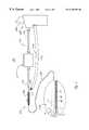
- FIG. 1shows a cryogenic treatment system 100 illustrating representative elements thereof.
- System 100includes a treatment catheter 110 having a handle 110 a , and elongated cryogen transporting body 110 b and a catheter tip 110 c .
- the catheter 110is connected by various conduits or cables to a console 120 which may, for example, have a display monitor 120 a and other data entry or display accessories such as a keyboard, a printer and the like.
- the console 120is connected to the catheter by various lines 115 which may include a coolant injection line 115 a , a coolant return line 115 b , and electrical cabling 115 c which carries outputs of various cardiac sensing, thermal sensing, mapping or other elements as may be used for catheter treatment or monitoring.
- the handle 110 ais equipped with input ports for an electrical connector 111 , a coolant injection tube connector 112 , and a return tube connector 113 . These connect by various internal junctions or tubes passing through the handle and elongated body 110 b to the distal tip of the catheter.
- the handlemay also include various control assemblies, e.g., switches or valves, as well a safety detection or shutdown elements (not illustrated).
- the coolantis carried to the tip through a tube 1 and enters a chamber 3 at the end of the catheter tip 110 c via a nozzle 2 at the end of the tube to expand in a small contained region forming the active region of the tip of the catheter.
- the tube 1may run concentrically within the elongated body 110 b , and the portion of the body lumen outside of tube 1 may form a return passage for spent coolant.
- the tube 1runs to the tip of the catheter where coolant exits from an orifice 2 at the end of the tube and returns through the annular space surrounding tube 1 , to the fluid return connector 113 of the handle.
- the return passage for expended coolantis a vacuum passage, thus assuring that leakage out of the catheter into the bloodstream does not occur.
- the chamberin which coolant is released from the nozzle 2 and returns to the return passage via annular opening 4 , defines the cooling region of the catheter tip.
- This chambermay be short, less than a few centimeters long, and located at the very tip of the catheter or slightly proximal thereto.
- a thermocouple 5 and one or more ring electrodes 8 a , 8 b , 8 cmay be positioned at the catheter tip for performing sensing and monitoring functions.
- phase change coolantis injected through the coolant line 1 to expand in the chamber 3 at the tip of the catheter, and return via a vacuum or suction passage to the return connection 113 at the catheter handle.
- the phase change materialis provided at ambient temperature but relatively high pressure through the handle and body 110 a , 110 b of the catheter, such that cooling only occurs upon release of pressure and expansion within the chamber 3 at the tip of the catheter.
- Operation of this deviceinvolves controlling the timing and amount of coolant injected through the inlet tube 1 at the injection pressure, which may, for example, be a pressure of about 400 psig.
- the entire catheteris dimensioned to fit in a No. 9 French introducer or smaller.
- cooling flowis enhanced by placing a plate or partition or other body within the catheter chamber 3 to condition flow from the coolant inlet or nozzle, to the coolant outlet or vacuum return passage.
- FIG. 2is a schematic illustration of the invention.
- a bullet-shaped capsuch as a machined metal end piece 7 a forms a continuous wall 24 defining a closed tip of the cooling chamber.
- a plate Pis positioned within the catheter tip 110 c to condition flow of the coolant leaving the orifice 2 of the injection tube 1 .
- the presence of the plateserves to direct or define the flow of the fluid entering the chamber.
- the plate Pmay lie adjacent to the nozzle 2 along the direction of fluid ejection to provide a bounding surface or boundary condition for guiding, smoothing or otherwise conditioning the flow.
- the platethen acts to reduce fluctuations in cooling which would otherwise occur due to the irregular or transient formation or movement of drops, bubbles, conflicting flow paths and the like in the flowing, expanding coolant.
- the plate Pmay be positioned as a flow director, or may operate together with another surface as a flow barrier so as to define a subregion of the chamber which is preferentially cooled, thus concentrating the cooling power of the fluid stream in a smaller region.
- the plateis formed as a partition or subdivider 10 in the form of a thin wall which preferably extends entirely from side to side to divide the tip interior, and is supported in part by a cross-wall which rises from the lower circumference (as shown).
- the cross-wall 10 amay operate as a barrier defining the proximal inlet of the chamber 3 and blocking access to the vacuum return lumen at that position so that the cryofluid is made to circulate unidirectionally parallel to and around the end of the partition 10 in its flow to reach the vacuum return opening.
- This wall 10 amay also be located closer to the distal end, e.g., at the position marked x near the end wall of the tip, with the inlet 2 extending to that point so that together with partition P it closes off a subregion and defines an inert side W i positioned so that all coolant from the tube is directed toward the other side or remaining portion W c of the interior and its wall portion is preferentially cooled.
- the partition 10isolates the entire lower (as shown) region of the wall to prevent it from being subjected to thermal cooling, and more effectively channels all coolant to the small end chamber 3 and upper side W c .
- the inlet tube 1need not pass through a blocking wall 10 a but may be positioned by a cross bar 10 b .
- the bar 10 bdoes not obstruct the available vacuum return path, and allows the partition 10 , blocking support 10 a (if one is used) and outlet 2 to each be positioned independently of the other.
- FIGS. 3B and 3Cillustrate other embodiments, in which an internal partition 10 ′ operates to condition flow for enhancing cooling of the external surface region of the catheter tip.
- the partition 10 ′substantially bisects into two partial chambers 11 , 12 , and the inlet nozzle 2 is positioned in one chamber 12 while the vacuum return outlet 4 opens into the other partial chamber 11 .
- Coolantthus circulates along the length of the tip on one side of the partition 10 ′, around the end of the partition and along back to the vacuum outlet 4 , thus being channeled to run against the internal perimeter surface of the catheter tip wall. In this manner flow is made unidirectional and relatively smooth, while being urged outwardly to the peripheral region against the wall.
- a curved partition 10 ′serves to define first chamber which is thin but of large surface area and experiences a high rate of flow of cryofluid against its wall, while increasing the area of vacuum return entry on the other side of the partition.
- partitionsmay be advantageously formed of a membrane divider or a thin plate.
- FIGS. 4A and 4Billustrate embodiments with a tip construction similar to that of FIG. 2 .
- FIG. 2illustrates a cross section along the longitudinal direction of a catheter tip, showing a tubular catheter body forming the major part of the catheter tip assembly, and a separate bullet-shaped tip portion 24 formed as a shell piece that closes the end and provides the expansion chamber 3 (FIG. 1 ).
- the separation plate 10extends for the length of the chamber 3 , and the injection tube 1 enters along one side so that its output is confined by the separation plate 10 ′ to run along the lower wall of the chamber.
- a thermocouple wireextends to and is anchored at the tip of the device.
- the coolant having passed through the lower chamberflows around the plate 10 ′ through the upper chamber, so that all flow has been directed along an elongated path running against the peripheral wall of the catheter tip region.
- this constructionis readily implemented by assembly of the separate components together to form a closed tip catheter chamber.
- the overall cross-sectional areais substantially less than a square centimeter, and the tip assembled in this manner may achieve a flow chamber construction of precise dimension and flow characteristics while being made of conventional polymer materials with ample safety margin to withstand the pressure and temperature cycles involved in its operation.
- FIGS. 4A and 4Bshow perspective views of a two tip assemblies similar to that of FIG. 2 in two alternate constructions, illustrating different locations for the divider plate to restrict the coolant region to a greater or lesser sub-portion along the length of the catheter tip.
- these Figuresfurther illustrate internal cables or wires 26 a , 26 b which may be mechanical pull wires for steering or control, or electrical wires, for example, for temperature or other sensing operations. As illustrated, these are seated in side recesses 1000 in a molded tip piece; more than two such recesses may be provided to accommodate both steering and sensing cabling at different axial or radial positions.
- the plate 20(FIG. 4A) or 20 ′ (FIG. 4B) is formed as an “L” or bracket shaped insertion piece, with an elongated partition portion P′ extending along the axial direction, and a cross-support or end face S securing and positioning the plate in the chamber.
- the injection tubepasses through the support S to be positioned on one side of the plate.
- the support Sleaves a partial circumference of the chamber open, to serve as the coolant return port from the downstream sub-chamber and define the direction of flow through the chamber.
- the partition within the expansion chambermay serve simply to condition flow, may limit flow to a particular subregion of the catheter tip, or may actively direct the flow against the peripheral wall of the catheter to enhance cooling in a portion or in the entirety of the tip wall, thus tailoring or improving one or more of the heat transfer contact surface or rate, the uniformity and the repeatability of cooling regimens.
- the inventionalso contemplates that in addition to a membrane or plate serving as the flow enhancement surface, cooling may be enhanced by shaped or contoured surfaces that channel the coolant or eliminate turbulence without reducing the active cooled surface area of the tip.
- a membrane or plate serving as the flow enhancement surfacecooling may be enhanced by shaped or contoured surfaces that channel the coolant or eliminate turbulence without reducing the active cooled surface area of the tip.
- One such embodimentis illustrated by the flow director 30 of FIG. 5 .
- This embodimentpossesses an outer surface 31 which is generally cylindrical or frusto-conical in shape, and serves to direct flow against the catheter tip wall.
- the surface 31may possess spiral ridges or flutes to smooth the flow and prevent turbulence as the entering coolant stream expands outwardly and assumes a flow direction back toward the vacuum return line formed by the catheter body lumen.
- the outer surface 31 of the flow director 30may curve inwardly to form a nozzle 2 a which initiates and smooths the influx of coolant
- the flow conditionermay take other forms, and may have a shape and position configured to both direct and smooth the flow of coolant.
- FIGS. 9A and 9Billustrate such a flow conditioning body in two different catheters 400 , 500 , respectively.
- FIG. 9Ashows a flow director body 406 having the form of a tear-drop shaped insert fastened about the coolant injection tube 401 .
- Body 406may be formed of any suitable material compatible with the refrigerant, and may be fastened by bonding, soldering, welding or molding it to the injection tube.
- the tube 401may extend only into the central passage of body 406 , so that the refrigerant exits from the distal orifice 406 a of the body 406 , or the tube 401 may extend distally beyond the end of the insert 406 and possess a perforated delivery section 402 which emits the refrigerant into an expansion region at the distal tip interior.
- the flow in the distal expansion chamberis turbulent, and the curved distal face of the body 406 serves to channel the expanded refrigerant through a narrow passage at the inner wall of the conductive tip assembly.
- the inserthas an aerodynamic shape that causes an increase in the velocity of the vaporizing refrigerant flowing proximally, and forces it to stay in contact with the tip wall.
- the turbulent flow generated by the sudden expansion of the refrigerant at the distal end of the tip cavitywill tend to be converted into a laminar one as the velocity of the vapor increases towards the proximal end of the insert.
- the catheter 400is illustrated as having a closed tip formed by an end cap 475 machined from metal so as to have a relatively thick thermally conductive wall 424 against which the cooling flow is urged.
- the insert 406defines an expansion chamber 403 at the refrigerant nozzle or outlet, and the fluid flow provides enhanced thermal contact to the inner wall proximally thereof, so that the entire tip is effectively cooled.
- FIG. 9Bshows a similar flow conditioning body 506 positioned in the tip of a cryocatheter 500 .
- Catheter 500has a drawn or spun tip 575 , with a wall 524 formed of a sheet of material having a substantially uniform thickness.
- the interior of the expansion chamber 503may be enlarged, and a larger flow conditioning body 506 directs the expanding refrigerant against a tip interior wall of larger surface area, permitting an increased cooling capacity.
- the position of greatest diameter of the body 406 or 506may be seen to produce an annular venturi-like tapered flow passage extending between the distal refrigerant expansion chamber and the refrigerant return opening of the catheter shaft.
- a second such tapering passagemay be formed between the inner curving shoulder 508 of the formed tip assembly and the proximal surface of the insert body 506 .
- a cathetermay include a means for warming or thawing of tissue that has been cooled.
- a warming fluidis supplied to the catheter tip.
- the warming fluidis supplied following the application of cryogenic treatment, and thus is applied in a distinct time interval separate from the application of cold.
- Thiswill generally be affected by a controller which operates under programmed or push button control, using basic components or switching regimens similar to ones of a known type to control the various elements which will be described further below.
- the cathetermay be configured to heat the inlet tube, for example, by use of an electrical heater within the catheter body or tip region so that the fluid supplied therethrough warms, rather than cools, the catheter tip area before returning to the catheter handle.
- a separate warming fluid supply tube or sub-lumenis provided to carry a distinct warming fluid having characteristics different from the coolant, and better suited to a warming function, for circulation through the catheter tip.
- a heat transfer fluidmay be employed which remains liquid at non-cryogenic or at biological temperature.
- the existing vacuum return linemay serve as the return path for the fluid which has entered the catheter tip.
- the return lumenmay be formed of or partitioned into several paths to separately effect circulation of the two fluids.
- the inventionmay further include a switching valve in the region of the handle for inter-connecting the warming supply line to the vacuum return port during time intervals when warming fluid is not needed at the tip region. This causes the additional fluid line to serve as an additional return line, thus increasing the circulation rate or capacity during operation of the cooling cycle in addition to providing a separate warming fluid during the warming cycles.
- the catheter 50may also be implemented as a linear cryocatheter, with the internal warming fluid chamber formed by a thin plastic membrane that is effective to warm a non-inflating cooling tip, such as a metal-wrapped cylindrical catheter tip.
- FIG. 6illustrates a construction for providing warming fluid to another embodiment of a cryocatheter in accordance with the invention, configured as an angioplasty balloon catheter designed for physical enlargement of and thermal treatment of the interior of a vessel.
- the temperature controlled chamber at the catheter endis an expansion balloon 6000 provided with a partition that is preferably flexible and takes the form of a separating membrane 30 positioned along the path between the warming fluid inlet 6100 and the vacuum outlet 6200 , forcing the fluid to circulate from one side to the other of the treatment chamber 6000 .
- the refrigerant injection tube 1may enter centrally to introduce a flow which is guided by the adjacent membrane 30 and cools the whole chamber as described above; the warming fluid may be provided to the tip via a sector of the main body lumen 1 that extends to the tip region.
- a non-inflatable or linear cryotip(FIG. 2, for example)
- applicantalso contemplated a construction that restricts all circulation to a partial cross-section of the chamber.
- a dividing plate or membrane 13 amay entirely separate the interior into a closed chamber 13 , and an expansion/return chamber 14 .
- the supply nozzle 2opens into the chamber 14 , and coolant circulates along its length to the return passage in the catheter body.
- the other chamber 13remains empty, and defines a thermally insulating buffer extending along one side of the chamber.
- the membrane 13 aneed not be straight, but may be curved as in the axial flow-divider constructions of FIGS. 3A-3C.
- FIG. 6Aillustrates a further embodiment 50 suitable for both cooling and warming a restenosis catheter.
- a double balloon layeris formed in the active balloon expansion region, with the inner balloon 51 fed by the coolant injection tube 1 so that, as indicated in phantom, it is urged outwardly against the wall of the catheter when coolant flows from the nozzle 2 .
- the proximal end 51 a of the inner balloonopens to allow coolant to pass directly to the vacuum return passage.
- the balloonshrinks, and a separate space 3 ′ is formed between the outer wall and the inner balloon, to which warming fluid is fed and may circulate when the coolant pressure at the center has fallen, i.e., during the period at the end of a cooling cycle.
- the balloonforms a membrane partition that urges the warming fluid toward the surrounding peripheral region but does not interfere with coolant heat transfer during the cooling cycle.
- a dividing plate or partitionmay be positioned within the catheter body to limit the warming or cooling effect to one side or the other.
- the devicewhen used for a restenosis balloon, is a symmetric balloon body formed of elastomeric material and adapted to heat or cool uniformly around its whole circumference when inflated by fluid for angioplasty operation.
- each of the described cathetersmay further include one or more sensors, electrodes and control elements of conventional type, such as steering elements, temperature sensing elements and additional lumens for sampling blood gases, enzymes or other material at the catheter tip.
- the elements of constructionmay include any conventional form of catheter wall, tip movement mechanism, steering wiggler and other elements, such as stiffening, torquing, tensioning or spring wrapped strengthening members of the type known in the art for deployment or use in the construction and design of movable catheter tip assemblies. Mapping electrodes and other signal emitting or receiving electrodes may also be incorporated in the tip structure.
- one particularly advantageous embodiment of the inventionincludes an orientation-sensing system 200 for determining the tissue contacting side of the catheter tip.
- a series of at least two sensing elements 201 a and 201 bare positioned at fixed intervals around the tip circumference, and are connected via leads 7000 in the catheter body to a processor/display unit 202 .
- the elements 201 a and 201 bmay be a pair of temperature sensors disposed on opposite sides of the tip.
- the processor/display 202senses the difference in sensed temperature to determine which side of the tip lies in contact with adjacent tissue.
- the catheter assemblyitself may be configured with a single-plane steering wire to bend toward or away from tissue in the plane of the two sensors.
- the displaymay further indicate whether the active side of the tip is urged toward or away from tissue contact.
- the sensors 201 a and 201 bmay be implemented as impedance monitoring or signal emitting electrodes.
- the processor/display 202may compare signal strength of the electrodes 201 a and 201 b to determine which side of the tip resides in contact with tissue.
- the electrodesmay carry high frequency signals of two different frequencies and the processor may simply detect which of the two frequencies predominates in the signal that has been transmitted through tissue. More than two such electrodes may be provided, and the unit 202 may also employ other detection criteria, such as differential sensing between several of the electrodes on the tip to detect local impedance changes indicative of presence of blood, tissue boundaries or other such features, using this information to distinguish the tip contact orientation.
- FIG. 8shows a sectional end view, taken midway along the length of a catheter tip 300 in one such embodiment.
- the cooling injection tube 1enters the tip 300 centrally, and a separating plate or membrane 310 divides the cooling chamber 3 into two half-chambers ( 8000 a and 8000 b respectively) extending back to the main body of the catheter.
- a second plate or membrane 311which may be a thin film flexibly biased against the plate 310 so that it spreads apart only when warming fluid is injected between the walls 310 , 311 , provides warming fluid manifolds ( 8100 a and 8100 b respectively) that fill the thermal contact portion of the tip and channels warming fluid back toward the return passage.
- This manifoldmay be provided with warming fluid, in turn, via a separate supply tube extending from the handle through the catheter body, or the catheter body itself may be subdivided by one or more septa to provide one or more isolated sectors of its cross-sectional flow path dedicated to the supply of warming fluid to the tip.
Landscapes
- Health & Medical Sciences (AREA)
- Surgery (AREA)
- Life Sciences & Earth Sciences (AREA)
- Nuclear Medicine, Radiotherapy & Molecular Imaging (AREA)
- Biomedical Technology (AREA)
- Engineering & Computer Science (AREA)
- Otolaryngology (AREA)
- Heart & Thoracic Surgery (AREA)
- Medical Informatics (AREA)
- Molecular Biology (AREA)
- Animal Behavior & Ethology (AREA)
- General Health & Medical Sciences (AREA)
- Public Health (AREA)
- Veterinary Medicine (AREA)
- Surgical Instruments (AREA)
Abstract
Description
Claims (19)
Priority Applications (1)
| Application Number | Priority Date | Filing Date | Title |
|---|---|---|---|
| US09/356,433US6270493B1 (en) | 1999-07-19 | 1999-07-19 | Cryoablation structure |
Applications Claiming Priority (1)
| Application Number | Priority Date | Filing Date | Title |
|---|---|---|---|
| US09/356,433US6270493B1 (en) | 1999-07-19 | 1999-07-19 | Cryoablation structure |
Publications (1)
| Publication Number | Publication Date |
|---|---|
| US6270493B1true US6270493B1 (en) | 2001-08-07 |
Family
ID=23401406
Family Applications (1)
| Application Number | Title | Priority Date | Filing Date |
|---|---|---|---|
| US09/356,433Expired - LifetimeUS6270493B1 (en) | 1999-07-19 | 1999-07-19 | Cryoablation structure |
Country Status (1)
| Country | Link |
|---|---|
| US (1) | US6270493B1 (en) |
Cited By (161)
| Publication number | Priority date | Publication date | Assignee | Title |
|---|---|---|---|---|
| US6471693B1 (en)* | 1999-09-10 | 2002-10-29 | Cryocath Technologies Inc. | Catheter and system for monitoring tissue contact |
| US6537271B1 (en)* | 2000-07-06 | 2003-03-25 | Cryogen, Inc. | Balloon cryogenic catheter |
| US6551309B1 (en)* | 2000-09-14 | 2003-04-22 | Cryoflex, Inc. | Dual action cryoprobe and methods of using the same |
| US6579287B2 (en) | 2001-10-09 | 2003-06-17 | Cryocath Technologies Inc. | Cryosurgical ablation device having sequential injection and method therefor |
| US6579288B1 (en)* | 1997-10-10 | 2003-06-17 | Scimed Life Systems, Inc. | Fluid cooled apparatus for supporting diagnostic and therapeutic elements in contact with tissue |
| US6585728B2 (en)* | 2001-05-25 | 2003-07-01 | Biosense Webster, Inc. | Cryoablation catheter with an improved gas expansion chamber |
| US6602276B2 (en) | 1998-03-31 | 2003-08-05 | Innercool Therapies, Inc. | Method and device for performing cooling- or cryo-therapies for, e.g., angioplasty with reduced restenosis or pulmonary vein cell necrosis to inhibit atrial fibrillation |
| US6616657B2 (en)* | 1998-05-05 | 2003-09-09 | Cardiac Pacemakers, Inc. | RF ablation catheter tip electrode with multiple thermal sensors |
| US20030187428A1 (en)* | 1999-08-23 | 2003-10-02 | Miriam Lane | Endovascular cryotreatment catheter |
| US20030199862A1 (en)* | 2002-04-22 | 2003-10-23 | Simpson John A. | RF ablation apparatus and method using multi-frequency energy delivery |
| US6685732B2 (en) | 1998-03-31 | 2004-02-03 | Innercool Therapies, Inc. | Method and device for performing cooling- or cryo-therapies for, e.g., angioplasty with reduced restenosis or pulmonary vein cell necrosis to inhibit atrial fibrillation employing microporous balloon |
| US20040024391A1 (en)* | 2002-01-04 | 2004-02-05 | Galil Medical Ltd. | Apparatus and method for protecting tissues during cryoablation |
| US20040024392A1 (en)* | 2002-08-05 | 2004-02-05 | Lewis James D. | Apparatus and method for cryosurgery |
| US20040097964A1 (en)* | 2001-01-17 | 2004-05-20 | Dhindsa Avtar S. | Endoscopic stone extraction device with improved basket |
| US20040186467A1 (en)* | 2003-03-21 | 2004-09-23 | Swanson David K. | Apparatus for maintaining contact between diagnostic and therapeutic elements and tissue and systems including the same |
| US20040230131A1 (en)* | 2003-02-21 | 2004-11-18 | Kassab Ghassan S. | System and method for measuring cross-sectional areas and pressure gradients in luminal organs |
| US20040243117A1 (en)* | 2002-12-11 | 2004-12-02 | Lentz David J. | Catheter system for performing a single step cryoablation |
| US20040243118A1 (en)* | 2001-06-01 | 2004-12-02 | Ayers Gregory M. | Device and method for positioning a catheter tip for creating a cryogenic lesion |
| US20040243119A1 (en)* | 1999-08-23 | 2004-12-02 | Cryocath Technologies Inc. | Endovascular cryotreatment catheter |
| US20050090881A1 (en)* | 2003-04-17 | 2005-04-28 | Frank Jeffrey I. | Heat transfer probe |
| US6905494B2 (en) | 1998-03-31 | 2005-06-14 | Innercool Therapies, Inc. | Method and device for performing cooling- or cryo-therapies for, e.g., angioplasty with reduced restenosis or pulmonary vein cell necrosis to inhibit atrial fibrillation employing tissue protection |
| US20050187544A1 (en)* | 2004-02-19 | 2005-08-25 | Scimed Life Systems, Inc. | Cooled probes and apparatus for maintaining contact between cooled probes and tissue |
| US6939350B2 (en) | 2001-10-22 | 2005-09-06 | Boston Scientific Scimed, Inc. | Apparatus for supporting diagnostic and therapeutic elements in contact with tissue including electrode cooling device |
| US6942661B2 (en) | 2000-08-30 | 2005-09-13 | Boston Scientific Scimed, Inc. | Fluid cooled apparatus for supporting diagnostic and therapeutic elements in contact with tissue |
| US20050203434A1 (en)* | 2003-02-21 | 2005-09-15 | Kassab Ghassan S. | Devices, systems and methods for plaque type determination |
| US20050228367A1 (en)* | 1999-01-25 | 2005-10-13 | Marwan Abboud | Leak detection system for catheter based medical device |
| US20050251122A1 (en)* | 2004-05-10 | 2005-11-10 | Scimed Life Systems, Inc. | Clamp based low temperature lesion formation apparatus, system and methods |
| US20050251123A1 (en)* | 2004-05-10 | 2005-11-10 | Scimed Life Systems, Inc. | Low temperature lesion formation apparatus, systems and methods |
| EP1474059A4 (en)* | 2002-01-04 | 2005-11-30 | Galil Medical Ltd | Apparatus and method for protecting the neurovascular bundle during cryosurgical treatment of the prostate |
| US20050283146A1 (en)* | 2004-06-17 | 2005-12-22 | Lentz David J | Thermally extended spiral cryotip for a cryoablation catheter |
| US20060036302A1 (en)* | 2004-05-28 | 2006-02-16 | Kasza Kenneth E | Methods of inducing protective hypothermia of organs |
| US7001378B2 (en) | 1998-03-31 | 2006-02-21 | Innercool Therapies, Inc. | Method and device for performing cooling or cryo-therapies, for, e.g., angioplasty with reduced restenosis or pulmonary vein cell necrosis to inhibit atrial fibrillation employing tissue protection |
| US20060122590A1 (en)* | 2004-12-06 | 2006-06-08 | Galil Medical Ltd. | Gas-heated gas-cooled cryoprobe utilizing electrical heating and a single gas source |
| US20060161232A1 (en)* | 2005-01-18 | 2006-07-20 | Kasza, Oras and Son to The University of Chicago | Phase-change particulate ice slurry coolant medical delivery tubing and insertion devices |
| US20060212026A1 (en)* | 2005-03-07 | 2006-09-21 | Marwan Abboud | Fluid control system for a medical device |
| US20060253114A1 (en)* | 2001-11-02 | 2006-11-09 | Vahid Saadat | Methods and apparatus for cryo-therapy |
| US20060253025A1 (en)* | 2005-04-21 | 2006-11-09 | Kaufman Jonathan J | Ultrasonic Bone Assessment Apparatus and Method |
| US20070056313A1 (en)* | 2005-09-15 | 2007-03-15 | Kasza Kenneth E | Medical ice slurry production device |
| US20070208329A1 (en)* | 2004-12-10 | 2007-09-06 | Jim Ward | Ablative treatment of atrial fibrillation via the coronary sinus |
| US7291144B2 (en) | 1998-03-31 | 2007-11-06 | Innercool Therapies, Inc. | Method and device for performing cooling- or cryo-therapies for, e.g., angioplasty with reduced restenosis or pulmonary vein cell necrosis to inhibit atrial fibrillation |
| US20070277550A1 (en)* | 2000-08-09 | 2007-12-06 | Cryocor, Inc. | Refrigeration source for a cryoablation catheter |
| US20080097251A1 (en)* | 2006-06-15 | 2008-04-24 | Eilaz Babaev | Method and apparatus for treating vascular obstructions |
| WO2008005388A3 (en)* | 2006-06-30 | 2008-06-05 | Dtherapeutics Llc | Localization of body lumen junctions |
| US20080194996A1 (en)* | 2003-02-21 | 2008-08-14 | Kassab Ghassan S | Device, system and method for measuring cross-sectional areas in luminal organs |
| US20080294041A1 (en)* | 2006-01-25 | 2008-11-27 | Kassab Ghassan S | Devices, Systems and Methods for Determining Sizes of Vessels |
| US20080306475A1 (en)* | 2007-06-08 | 2008-12-11 | Lentz David J | Cryo-applicator cross-section configuration |
| USRE40815E1 (en) | 1999-06-25 | 2009-06-30 | Ams Research Corporation | Control system for cryosurgery |
| US20090204029A1 (en)* | 2003-02-21 | 2009-08-13 | Kassab Ghassan S | Systems and methods for determining phasic cardiac cycle measurements |
| US20090204134A1 (en)* | 2003-02-21 | 2009-08-13 | Kassab Ghassan S | Devices, systems, and methods for removing stenotic lesions from vessels |
| WO2009103448A1 (en)* | 2008-02-21 | 2009-08-27 | Erbe Elektromedizin Gmbh | Cryosurgical instrument |
| US7582083B2 (en) | 2004-05-10 | 2009-09-01 | Boston Scientific Scimed, Inc. | Probe based low temperature lesion formation apparatus, systems and methods |
| US20090234345A1 (en)* | 2008-03-13 | 2009-09-17 | Raphael Hon | Cryo-ablation refrigerant distribution catheter |
| US20090264876A1 (en)* | 2006-07-28 | 2009-10-22 | Centre Hospitalier Universitaire De Quebec | Probe, sleeve, system, method and kit for performing percutaneous thermotherapy |
| US7608072B2 (en) | 2003-12-02 | 2009-10-27 | Boston Scientific Scimed, Inc. | Surgical methods and apparatus for maintaining contact between tissue and electrophysiology elements and confirming whether a therapeutic lesion has been formed |
| US20090299355A1 (en)* | 2008-05-27 | 2009-12-03 | Boston Scientific Scimed, Inc. | Electrical mapping and cryo ablating with a balloon catheter |
| US7727228B2 (en) | 2004-03-23 | 2010-06-01 | Medtronic Cryocath Lp | Method and apparatus for inflating and deflating balloon catheters |
| US20100152607A1 (en)* | 2003-02-21 | 2010-06-17 | Kassab Ghassan S | Devices, systems, and methods for measuring parallel tissue conductance, luminal cross-sectional areas, fluid velocity, and/or determining plaque vulnerability using temperature |
| US20100168836A1 (en)* | 2003-02-21 | 2010-07-01 | Kassab Ghassan S | Balloon sizing of valve annulus for percutaneous valves |
| US20100174271A1 (en)* | 2003-02-21 | 2010-07-08 | Kassab Ghassan S | Devices, systems, and methods for removing contrast from luminal organs |
| US20100179527A1 (en)* | 2009-01-15 | 2010-07-15 | Boston Scientific Scimed, Inc. | Controlling Depth of Cryoablation |
| US20100222786A1 (en)* | 2003-02-21 | 2010-09-02 | Kassab Ghassan S | Devices, systems, and methods for removing targeted lesions from vessels |
| US20100241113A1 (en)* | 2009-03-20 | 2010-09-23 | Boston Scientific Scimed, Inc. | Protecting the phrenic nerve while ablating cardiac tissue |
| US20100241114A1 (en)* | 2009-03-20 | 2010-09-23 | Salvatore Privitera | Cryogenic probe |
| WO2010124178A3 (en)* | 2009-04-23 | 2011-03-31 | Reset Medical, Inc. | Apparatuses and methods for applying a cryogenic effect to tissue and cutting tissue |
| US20110190750A1 (en)* | 2010-01-29 | 2011-08-04 | Medtronic Cryocath Lp | Multifunctional ablation device |
| US20110196255A1 (en)* | 2010-02-05 | 2011-08-11 | Kassab Ghassan S | Devices, systems, and methods for measuring parallel tissue conductance, luminal cross-sectional areas, fluid velocity, and/or determining plaque vulnerability using temperature |
| US8016822B2 (en) | 2005-05-28 | 2011-09-13 | Boston Scientific Scimed, Inc. | Fluid injecting devices and methods and apparatus for maintaining contact between fluid injecting devices and tissue |
| US20110245821A1 (en)* | 2010-03-30 | 2011-10-06 | Medtronic ATS Medical, Inc. | Cryoprobe having internal warming fluid capabilities |
| US8052676B2 (en) | 2003-12-02 | 2011-11-08 | Boston Scientific Scimed, Inc. | Surgical methods and apparatus for stimulating tissue |
| WO2011119279A3 (en)* | 2010-03-25 | 2011-11-24 | Icecure Medical Ltd. | Cryosurgical instrument with enhanced heat transfer |
| US20120046655A1 (en)* | 2010-08-18 | 2012-02-23 | Besch Hansjoerg | Device for the fluid-conveying connection of at least one application probe with a supply tubing set, and handle for a surgical instrument |
| US20120065630A1 (en)* | 2010-09-15 | 2012-03-15 | Nir Berzak | Cryosurgical instrument for treating large volume of tissue |
| US8163000B2 (en) | 1998-01-23 | 2012-04-24 | Innercool Therapies, Inc. | Selective organ cooling catheter with guidewire apparatus and temperature-monitoring device |
| US20120165802A1 (en)* | 2010-12-27 | 2012-06-28 | Medtronic Cryocath Lp | Method and system to prevent complete obstruction in catheter in case of a kink |
| US20130060242A1 (en)* | 2008-12-23 | 2013-03-07 | Cryomedix Llc | Isotherm-based tissue ablation control method |
| US8491636B2 (en) | 2004-03-23 | 2013-07-23 | Medtronic Cryopath LP | Method and apparatus for inflating and deflating balloon catheters |
| US20130190747A1 (en)* | 2012-01-10 | 2013-07-25 | Josef V. Koblish | Electrophysiology system and methods |
| US20140180278A1 (en)* | 2005-11-18 | 2014-06-26 | Medtronic Cryocath Lp | System and method for monitoring bioimpedance and respiration |
| US8801693B2 (en) | 2010-10-29 | 2014-08-12 | C. R. Bard, Inc. | Bioimpedance-assisted placement of a medical device |
| US8886301B2 (en) | 2003-02-21 | 2014-11-11 | 3Dt Holdings, Llc | Impedance devices for obtaining conductance measurements within luminal organs |
| US8950188B2 (en) | 2011-09-09 | 2015-02-10 | General Electric Company | Turning guide for combustion fuel nozzle in gas turbine and method to turn fuel flow entering combustion chamber |
| EP2859860A1 (en)* | 2013-10-08 | 2015-04-15 | Erbe Elektromedizin GmbH | Multifunctional instrument |
| US9066672B2 (en) | 2011-10-27 | 2015-06-30 | 3Dt Holdings, Llc | Single injection methods for obtaining conductance measurements within luminal organs using impedance devices |
| US9265443B2 (en) | 2006-10-23 | 2016-02-23 | Bard Access Systems, Inc. | Method of locating the tip of a central venous catheter |
| US9277952B2 (en) | 2011-02-01 | 2016-03-08 | Channel Medsystems, Inc. | Cryogenic treatment systems |
| WO2016033683A1 (en)* | 2014-09-04 | 2016-03-10 | Medtronic Cryocath Lp | Cryoadhesive device for left atrial appendage occlusion |
| US9339206B2 (en) | 2009-06-12 | 2016-05-17 | Bard Access Systems, Inc. | Adaptor for endovascular electrocardiography |
| US9345422B2 (en) | 2006-10-23 | 2016-05-24 | Bard Acess Systems, Inc. | Method of locating the tip of a central venous catheter |
| US9370329B2 (en) | 2012-09-18 | 2016-06-21 | Boston Scientific Scimed, Inc. | Map and ablate closed-loop cooled ablation catheter |
| US9393072B2 (en) | 2009-06-30 | 2016-07-19 | Boston Scientific Scimed, Inc. | Map and ablate open irrigated hybrid catheter |
| US9402676B2 (en) | 2010-08-26 | 2016-08-02 | Cryomedix, Llc | Cryoablation balloon catheter and related method |
| US9408655B2 (en) | 2010-10-27 | 2016-08-09 | Cryomedix, Llc | Cryoablation apparatus with enhanced heat exchange area and related method |
| US9439707B2 (en) | 2011-03-25 | 2016-09-13 | Medtronic Cryocath Lp | Spray nozzle design for a catheter |
| US9445734B2 (en) | 2009-06-12 | 2016-09-20 | Bard Access Systems, Inc. | Devices and methods for endovascular electrography |
| US9456766B2 (en) | 2007-11-26 | 2016-10-04 | C. R. Bard, Inc. | Apparatus for use with needle insertion guidance system |
| US9462960B2 (en) | 2003-02-21 | 2016-10-11 | 3Dt Holdings, Llc | Impedance devices and methods of using the same to obtain luminal organ measurements |
| US9463064B2 (en) | 2011-09-14 | 2016-10-11 | Boston Scientific Scimed Inc. | Ablation device with multiple ablation modes |
| US9492097B2 (en) | 2007-11-26 | 2016-11-15 | C. R. Bard, Inc. | Needle length determination and calibration for insertion guidance system |
| US9521961B2 (en) | 2007-11-26 | 2016-12-20 | C. R. Bard, Inc. | Systems and methods for guiding a medical instrument |
| US9526440B2 (en) | 2007-11-26 | 2016-12-27 | C.R. Bard, Inc. | System for placement of a catheter including a signal-generating stylet |
| US9532724B2 (en) | 2009-06-12 | 2017-01-03 | Bard Access Systems, Inc. | Apparatus and method for catheter navigation using endovascular energy mapping |
| WO2016193125A3 (en)* | 2015-06-03 | 2017-01-19 | Koninklijke Philips N.V. | Cryotherapy systems |
| US9549685B2 (en) | 2007-11-26 | 2017-01-24 | C. R. Bard, Inc. | Apparatus and display methods relating to intravascular placement of a catheter |
| US9554716B2 (en) | 2007-11-26 | 2017-01-31 | C. R. Bard, Inc. | Insertion guidance system for needles and medical components |
| US9603659B2 (en) | 2011-09-14 | 2017-03-28 | Boston Scientific Scimed Inc. | Ablation device with ionically conductive balloon |
| US9636031B2 (en) | 2007-11-26 | 2017-05-02 | C.R. Bard, Inc. | Stylets for use with apparatus for intravascular placement of a catheter |
| US9636172B2 (en) | 2013-05-31 | 2017-05-02 | Medtronic Cryocath Lp | Compliant balloon with liquid injection |
| US9649048B2 (en) | 2007-11-26 | 2017-05-16 | C. R. Bard, Inc. | Systems and methods for breaching a sterile field for intravascular placement of a catheter |
| US9675257B2 (en) | 2013-03-15 | 2017-06-13 | 3Dt Holdings, Llc | Impedance devices and methods to use the same to obtain luminal organ measurements |
| US9681823B2 (en) | 2007-11-26 | 2017-06-20 | C. R. Bard, Inc. | Integrated system for intravascular placement of a catheter |
| US9734938B2 (en) | 2011-10-06 | 2017-08-15 | 3Dt Holdings, Llc | Devices and systems for obtaining conductance data and methods of manufacturing and using the same |
| US9743854B2 (en) | 2014-12-18 | 2017-08-29 | Boston Scientific Scimed, Inc. | Real-time morphology analysis for lesion assessment |
| US9839372B2 (en) | 2014-02-06 | 2017-12-12 | C. R. Bard, Inc. | Systems and methods for guidance and placement of an intravascular device |
| US9895183B2 (en) | 2013-09-17 | 2018-02-20 | Channel Medsystems, Inc. | Liner for cryogenic treatment systems |
| US9901714B2 (en) | 2008-08-22 | 2018-02-27 | C. R. Bard, Inc. | Catheter assembly including ECG sensor and magnetic assemblies |
| US9907513B2 (en) | 2008-10-07 | 2018-03-06 | Bard Access Systems, Inc. | Percutaneous magnetic gastrostomy |
| US9986917B2 (en) | 2014-02-13 | 2018-06-05 | Boston Scientific Scimed, Inc. | Endoluminal ostium sensor array device |
| US9993280B2 (en) | 2015-07-02 | 2018-06-12 | Medtronic Cryocath Lp | N2O thermal pressurization system by cooling |
| US10004875B2 (en) | 2005-08-24 | 2018-06-26 | C. R. Bard, Inc. | Stylet apparatuses and methods of manufacture |
| US10004551B2 (en) | 2009-06-01 | 2018-06-26 | Channel Medsystems, Inc. | Methods and apparatus for treatment of a body cavity or lumen |
| US10046139B2 (en) | 2010-08-20 | 2018-08-14 | C. R. Bard, Inc. | Reconfirmation of ECG-assisted catheter tip placement |
| US10159531B2 (en) | 2012-04-05 | 2018-12-25 | C. R. Bard, Inc. | Apparatus and methods relating to intravascular positioning of distal end of catheter |
| US10172538B2 (en) | 2003-02-21 | 2019-01-08 | 3Dt Holdings, Llc | Body lumen junction localization |
| US10231643B2 (en) | 2009-06-12 | 2019-03-19 | Bard Access Systems, Inc. | Apparatus and method for catheter navigation and tip location |
| WO2019055800A1 (en)* | 2017-09-14 | 2019-03-21 | Regents Of The University Of California | Cryoablation devices and related methods |
| US10349890B2 (en) | 2015-06-26 | 2019-07-16 | C. R. Bard, Inc. | Connector interface for ECG-based catheter positioning system |
| US10413211B2 (en) | 2003-02-21 | 2019-09-17 | 3Dt Holdings, Llc | Systems, devices, and methods for mapping organ profiles |
| US10420605B2 (en) | 2012-01-31 | 2019-09-24 | Koninklijke Philips N.V. | Ablation probe with fluid-based acoustic coupling for ultrasonic tissue imaging |
| US10433894B2 (en) | 2015-07-02 | 2019-10-08 | Medtronic Cryocath Lp | N2O liquefaction system with subcooling heat exchanger for medical device |
| US10449330B2 (en) | 2007-11-26 | 2019-10-22 | C. R. Bard, Inc. | Magnetic element-equipped needle assemblies |
| US10492844B2 (en) | 2017-05-25 | 2019-12-03 | Channel Medsystems, Inc. | Tethered system for cryogenic treatment |
| US10524691B2 (en) | 2007-11-26 | 2020-01-07 | C. R. Bard, Inc. | Needle assembly including an aligned magnetic element |
| US10524684B2 (en) | 2014-10-13 | 2020-01-07 | Boston Scientific Scimed Inc | Tissue diagnosis and treatment using mini-electrodes |
| US10543032B2 (en) | 2014-11-13 | 2020-01-28 | Adagio Medical, Inc. | Pressure modulated cryoablation system and related methods |
| US10568546B2 (en) | 2003-02-21 | 2020-02-25 | 3Dt Holdings, Llc | Devices and methods for sizing valve apertures and luminal organs |
| US10603105B2 (en) | 2014-10-24 | 2020-03-31 | Boston Scientific Scimed Inc | Medical devices with a flexible electrode assembly coupled to an ablation tip |
| US10610279B2 (en) | 2014-04-10 | 2020-04-07 | Channel Medsystems, Inc. | Apparatus and methods for regulating cryogenic treatment |
| US10617459B2 (en) | 2014-04-17 | 2020-04-14 | Adagio Medical, Inc. | Endovascular near critical fluid based cryoablation catheter having plurality of preformed treatment shapes |
| US10667854B2 (en) | 2013-09-24 | 2020-06-02 | Adagio Medical, Inc. | Endovascular near critical fluid based cryoablation catheter and related methods |
| CN111372523A (en)* | 2017-09-13 | 2020-07-03 | 奥卓霍姆有限责任公司 | Medical device with CMUT array and solid state cooling and related methods and systems |
| US10751509B2 (en) | 2007-11-26 | 2020-08-25 | C. R. Bard, Inc. | Iconic representations for guidance of an indwelling medical device |
| US10864031B2 (en) | 2015-11-30 | 2020-12-15 | Adagio Medical, Inc. | Ablation method for creating elongate continuous lesions enclosing multiple vessel entries |
| US10973584B2 (en) | 2015-01-19 | 2021-04-13 | Bard Access Systems, Inc. | Device and method for vascular access |
| US10992079B2 (en) | 2018-10-16 | 2021-04-27 | Bard Access Systems, Inc. | Safety-equipped connection systems and methods thereof for establishing electrical connections |
| US11000205B2 (en) | 2012-04-05 | 2021-05-11 | Bard Access Systems, Inc. | Devices and systems for navigation and positioning a central venous catheter within a patient |
| US11000207B2 (en) | 2016-01-29 | 2021-05-11 | C. R. Bard, Inc. | Multiple coil system for tracking a medical device |
| US11051867B2 (en) | 2015-09-18 | 2021-07-06 | Adagio Medical, Inc. | Tissue contact verification system |
| CN113876412A (en)* | 2020-07-02 | 2022-01-04 | 瓦里安医疗系统公司 | Cryosurgical probe with enhanced thermal performance |
| WO2022035583A1 (en) | 2020-08-14 | 2022-02-17 | Adagio Medical, Inc. | Novel flow manifold for cryoablation catheter |
| US11373780B2 (en) | 2011-10-06 | 2022-06-28 | 3Dt Holdings, Llc | Methods to generate elongated wires having a metallic substrate thereon and devices comprising the same |
| US11504178B2 (en) | 2015-10-08 | 2022-11-22 | Channel Medsystems, Inc. | Exhaust collection bag for cryogenic treatment |
| US11517372B2 (en)* | 2005-12-06 | 2022-12-06 | St. Jude Medical, Atrial Fibrillation Division, Inc. | System and method for assessing lesions in tissue |
| US11564725B2 (en) | 2017-09-05 | 2023-01-31 | Adagio Medical, Inc. | Ablation catheter having a shape memory stylet |
| US11583329B2 (en) | 2017-08-04 | 2023-02-21 | Erbe Elektromedizin Gmbh | Cryosurgical instrument |
| US11628007B2 (en)* | 2018-09-14 | 2023-04-18 | Atricure, Inc. | Cryoprobe |
| US11684416B2 (en) | 2009-02-11 | 2023-06-27 | Boston Scientific Scimed, Inc. | Insulated ablation catheter devices and methods of use |
| US11744639B2 (en)* | 2008-11-11 | 2023-09-05 | Shifamed Holdings Llc | Ablation catheters |
| US11751930B2 (en) | 2018-01-10 | 2023-09-12 | Adagio Medical, Inc. | Cryoablation element with conductive liner |
| US11759268B2 (en) | 2012-04-05 | 2023-09-19 | C. R. Bard, Inc. | Apparatus and methods relating to intravascular positioning of distal end of catheter |
| US20240050142A1 (en)* | 2022-08-11 | 2024-02-15 | Varian Medical Systems, Inc. | Apparatuses and methods for ablation treatments including probes with handle heating |
| US12201340B2 (en) | 2011-03-25 | 2025-01-21 | Medtronic Cryocath Lp | Spray nozzle design for a catheter |
Citations (24)
| Publication number | Priority date | Publication date | Assignee | Title |
|---|---|---|---|---|
| US3425419A (en) | 1964-08-08 | 1969-02-04 | Angelo Actis Dato | Method of lowering and raising the temperature of the human body |
| US3859986A (en) | 1973-06-20 | 1975-01-14 | Jiro Okada | Surgical device |
| US3948269A (en) | 1973-08-31 | 1976-04-06 | Dragerwerk Aktiengesellschaft | Cryomedical device |
| US4946460A (en) | 1989-04-26 | 1990-08-07 | Cryo Instruments, Inc. | Apparatus for cryosurgery |
| US5078713A (en) | 1988-12-01 | 1992-01-07 | Spembly Medical Limited | Cryosurgical probe |
| US5211646A (en)* | 1990-03-09 | 1993-05-18 | Alperovich Boris I | Cryogenic scalpel |
| US5254116A (en) | 1991-09-06 | 1993-10-19 | Cryomedical Sciences, Inc. | Cryosurgical instrument with vent holes and method using same |
| US5275595A (en) | 1992-07-06 | 1994-01-04 | Dobak Iii John D | Cryosurgical instrument |
| US5281213A (en) | 1992-04-16 | 1994-01-25 | Implemed, Inc. | Catheter for ice mapping and ablation |
| US5281215A (en) | 1992-04-16 | 1994-01-25 | Implemed, Inc. | Cryogenic catheter |
| US5324286A (en) | 1993-01-21 | 1994-06-28 | Arthur A. Fowle, Inc. | Entrained cryogenic droplet transfer method and cryosurgical instrument |
| US5403309A (en) | 1992-07-31 | 1995-04-04 | Spembly Medical Limited | Cryosurgical ablation |
| US5423807A (en)* | 1992-04-16 | 1995-06-13 | Implemed, Inc. | Cryogenic mapping and ablation catheter |
| US5520682A (en) | 1991-09-06 | 1996-05-28 | Cryomedical Sciences, Inc. | Cryosurgical instrument with vent means and method using same |
| US5573532A (en) | 1995-01-13 | 1996-11-12 | Cryomedical Sciences, Inc. | Cryogenic surgical instrument and method of manufacturing the same |
| US5624392A (en) | 1990-05-11 | 1997-04-29 | Saab; Mark A. | Heat transfer catheters and methods of making and using same |
| US5716353A (en) | 1996-05-03 | 1998-02-10 | Urds, Corp. | Cryosurgical instrument |
| US5759182A (en) | 1993-11-09 | 1998-06-02 | Spembly Medical Limited | Cryosurgical probe with pre-cooling feature |
| US5800488A (en) | 1996-07-23 | 1998-09-01 | Endocare, Inc. | Cryoprobe with warming feature |
| US5833685A (en) | 1994-03-15 | 1998-11-10 | Tortal; Proserfina R. | Cryosurgical technique and devices |
| US5860971A (en)* | 1991-11-05 | 1999-01-19 | Spembly Cryosurgery Limited | Thawing of cryosurgical apparatus |
| US5860970A (en) | 1994-05-10 | 1999-01-19 | Spembly Medical Limited | Cryosurgical instrument |
| US5902299A (en)* | 1997-07-29 | 1999-05-11 | Jayaraman; Swaminathan | Cryotherapy method for reducing tissue injury after balloon angioplasty or stent implantation |
| US5971979A (en)* | 1997-12-02 | 1999-10-26 | Odyssey Technologies, Inc. | Method for cryogenic inhibition of hyperplasia |
- 1999
- 1999-07-19USUS09/356,433patent/US6270493B1/ennot_activeExpired - Lifetime
Patent Citations (25)
| Publication number | Priority date | Publication date | Assignee | Title |
|---|---|---|---|---|
| US3425419A (en) | 1964-08-08 | 1969-02-04 | Angelo Actis Dato | Method of lowering and raising the temperature of the human body |
| US3859986A (en) | 1973-06-20 | 1975-01-14 | Jiro Okada | Surgical device |
| US3948269A (en) | 1973-08-31 | 1976-04-06 | Dragerwerk Aktiengesellschaft | Cryomedical device |
| US5078713A (en) | 1988-12-01 | 1992-01-07 | Spembly Medical Limited | Cryosurgical probe |
| US4946460A (en) | 1989-04-26 | 1990-08-07 | Cryo Instruments, Inc. | Apparatus for cryosurgery |
| US5211646A (en)* | 1990-03-09 | 1993-05-18 | Alperovich Boris I | Cryogenic scalpel |
| US5624392A (en) | 1990-05-11 | 1997-04-29 | Saab; Mark A. | Heat transfer catheters and methods of making and using same |
| US5254116A (en) | 1991-09-06 | 1993-10-19 | Cryomedical Sciences, Inc. | Cryosurgical instrument with vent holes and method using same |
| US5520682A (en) | 1991-09-06 | 1996-05-28 | Cryomedical Sciences, Inc. | Cryosurgical instrument with vent means and method using same |
| US5860971A (en)* | 1991-11-05 | 1999-01-19 | Spembly Cryosurgery Limited | Thawing of cryosurgical apparatus |
| US5423807A (en)* | 1992-04-16 | 1995-06-13 | Implemed, Inc. | Cryogenic mapping and ablation catheter |
| US5281215A (en) | 1992-04-16 | 1994-01-25 | Implemed, Inc. | Cryogenic catheter |
| US5281213A (en) | 1992-04-16 | 1994-01-25 | Implemed, Inc. | Catheter for ice mapping and ablation |
| US5275595A (en) | 1992-07-06 | 1994-01-04 | Dobak Iii John D | Cryosurgical instrument |
| US5403309A (en) | 1992-07-31 | 1995-04-04 | Spembly Medical Limited | Cryosurgical ablation |
| US5324286A (en) | 1993-01-21 | 1994-06-28 | Arthur A. Fowle, Inc. | Entrained cryogenic droplet transfer method and cryosurgical instrument |
| US5759182A (en) | 1993-11-09 | 1998-06-02 | Spembly Medical Limited | Cryosurgical probe with pre-cooling feature |
| US5833685A (en) | 1994-03-15 | 1998-11-10 | Tortal; Proserfina R. | Cryosurgical technique and devices |
| US5860970A (en) | 1994-05-10 | 1999-01-19 | Spembly Medical Limited | Cryosurgical instrument |
| US5573532A (en) | 1995-01-13 | 1996-11-12 | Cryomedical Sciences, Inc. | Cryogenic surgical instrument and method of manufacturing the same |
| US5716353A (en) | 1996-05-03 | 1998-02-10 | Urds, Corp. | Cryosurgical instrument |
| US5800488A (en) | 1996-07-23 | 1998-09-01 | Endocare, Inc. | Cryoprobe with warming feature |
| US5800487A (en) | 1996-07-23 | 1998-09-01 | Endocare, Inc. | Cryoprobe |
| US5902299A (en)* | 1997-07-29 | 1999-05-11 | Jayaraman; Swaminathan | Cryotherapy method for reducing tissue injury after balloon angioplasty or stent implantation |
| US5971979A (en)* | 1997-12-02 | 1999-10-26 | Odyssey Technologies, Inc. | Method for cryogenic inhibition of hyperplasia |
Cited By (331)
| Publication number | Priority date | Publication date | Assignee | Title |
|---|---|---|---|---|
| US6579288B1 (en)* | 1997-10-10 | 2003-06-17 | Scimed Life Systems, Inc. | Fluid cooled apparatus for supporting diagnostic and therapeutic elements in contact with tissue |
| US8163000B2 (en) | 1998-01-23 | 2012-04-24 | Innercool Therapies, Inc. | Selective organ cooling catheter with guidewire apparatus and temperature-monitoring device |
| US8157794B2 (en) | 1998-03-31 | 2012-04-17 | Innercool Therapies, Inc. | Method and device for performing cooling-or cryo-therapies for, e.g., angioplasty with reduced restenosis or pulmonary vein cell necrosis to inhibit atrial fibrillation |
| US8043283B2 (en) | 1998-03-31 | 2011-10-25 | Innercool Therapies, Inc. | Method and device for performing cooling- or cryo-therapies for, e.g., angioplasty with reduced restenosis or pulmonary vein cell necrosis to inhibit atrial fibrillation |
| US7291144B2 (en) | 1998-03-31 | 2007-11-06 | Innercool Therapies, Inc. | Method and device for performing cooling- or cryo-therapies for, e.g., angioplasty with reduced restenosis or pulmonary vein cell necrosis to inhibit atrial fibrillation |
| US7449018B2 (en) | 1998-03-31 | 2008-11-11 | Innercool Therapies, Inc. | Method and device for performing cooling- or cryo-therapies for, e.g., angioplasty with reduced restenosis or pulmonary vein cell necrosis to inhibit atrial fibrillation employing microporous balloon |
| US6602276B2 (en) | 1998-03-31 | 2003-08-05 | Innercool Therapies, Inc. | Method and device for performing cooling- or cryo-therapies for, e.g., angioplasty with reduced restenosis or pulmonary vein cell necrosis to inhibit atrial fibrillation |
| US6905494B2 (en) | 1998-03-31 | 2005-06-14 | Innercool Therapies, Inc. | Method and device for performing cooling- or cryo-therapies for, e.g., angioplasty with reduced restenosis or pulmonary vein cell necrosis to inhibit atrial fibrillation employing tissue protection |
| US8043351B2 (en) | 1998-03-31 | 2011-10-25 | Innercool Therapies, Inc. | Method and device for performing cooling- or cryo-therapies for, e.g., angioplasty with reduced restenosis or pulmonary vein cell necrosis to inhibit atrial fibrillation employing tissue protection |
| US7001378B2 (en) | 1998-03-31 | 2006-02-21 | Innercool Therapies, Inc. | Method and device for performing cooling or cryo-therapies, for, e.g., angioplasty with reduced restenosis or pulmonary vein cell necrosis to inhibit atrial fibrillation employing tissue protection |
| US6685732B2 (en) | 1998-03-31 | 2004-02-03 | Innercool Therapies, Inc. | Method and device for performing cooling- or cryo-therapies for, e.g., angioplasty with reduced restenosis or pulmonary vein cell necrosis to inhibit atrial fibrillation employing microporous balloon |
| US7288089B2 (en) | 1998-03-31 | 2007-10-30 | Innercool Therapies, Inc. | Method and device for performing cooling- or cryo-therapies for, e.g., angioplasty with reduced restenosis or pulmonary vein cell necrosis to inhibit atrial fibrillation employing tissue protection |
| US6616657B2 (en)* | 1998-05-05 | 2003-09-09 | Cardiac Pacemakers, Inc. | RF ablation catheter tip electrode with multiple thermal sensors |
| US20050228367A1 (en)* | 1999-01-25 | 2005-10-13 | Marwan Abboud | Leak detection system for catheter based medical device |
| USRE40815E1 (en) | 1999-06-25 | 2009-06-30 | Ams Research Corporation | Control system for cryosurgery |
| USRE40868E1 (en)* | 1999-06-25 | 2009-08-11 | Cryocor, Inc. | Refrigeration source for a cryoblation catheter |
| US20040243119A1 (en)* | 1999-08-23 | 2004-12-02 | Cryocath Technologies Inc. | Endovascular cryotreatment catheter |
| US8298217B2 (en) | 1999-08-23 | 2012-10-30 | Medtronic Cryocath Lp | Endovascular cryotreatment catheter |
| US7527622B2 (en) | 1999-08-23 | 2009-05-05 | Cryocath Technologies Inc. | Endovascular cryotreatment catheter |
| US20030187428A1 (en)* | 1999-08-23 | 2003-10-02 | Miriam Lane | Endovascular cryotreatment catheter |
| US7300433B2 (en) | 1999-08-23 | 2007-11-27 | Cryocath Technologies Inc. | Endovascular cryotreatment catheter |
| US7648497B2 (en)* | 1999-08-23 | 2010-01-19 | Medtronic Cryocath Lp | Endovascular cryotreatment catheter |
| US20090182319A1 (en)* | 1999-08-23 | 2009-07-16 | Cryocath Technologies Inc. | Endovascular cryotreatment catheter |
| US20060030843A1 (en)* | 1999-08-23 | 2006-02-09 | Cryocath Technologies Inc. | Endovascular cryotreatment catheter |
| US6471693B1 (en)* | 1999-09-10 | 2002-10-29 | Cryocath Technologies Inc. | Catheter and system for monitoring tissue contact |
| US6730077B2 (en)* | 1999-09-10 | 2004-05-04 | Cryocath Technologies Inc. | Catheter system |
| US6537271B1 (en)* | 2000-07-06 | 2003-03-25 | Cryogen, Inc. | Balloon cryogenic catheter |
| US20070277550A1 (en)* | 2000-08-09 | 2007-12-06 | Cryocor, Inc. | Refrigeration source for a cryoablation catheter |
| US6942661B2 (en) | 2000-08-30 | 2005-09-13 | Boston Scientific Scimed, Inc. | Fluid cooled apparatus for supporting diagnostic and therapeutic elements in contact with tissue |
| US7303558B2 (en) | 2000-08-30 | 2007-12-04 | Boston Scientific Scimed, Inc. | Fluid cooled apparatus for supporting diagnostic and therapeutic elements in contact with tissue |
| US6551309B1 (en)* | 2000-09-14 | 2003-04-22 | Cryoflex, Inc. | Dual action cryoprobe and methods of using the same |
| US20040097964A1 (en)* | 2001-01-17 | 2004-05-20 | Dhindsa Avtar S. | Endoscopic stone extraction device with improved basket |
| US6585728B2 (en)* | 2001-05-25 | 2003-07-01 | Biosense Webster, Inc. | Cryoablation catheter with an improved gas expansion chamber |
| US20040243118A1 (en)* | 2001-06-01 | 2004-12-02 | Ayers Gregory M. | Device and method for positioning a catheter tip for creating a cryogenic lesion |
| EP1424950A4 (en)* | 2001-08-31 | 2005-11-30 | Cryocath Technologies Inc | Endovascular cryotreatment catheter |
| US6579287B2 (en) | 2001-10-09 | 2003-06-17 | Cryocath Technologies Inc. | Cryosurgical ablation device having sequential injection and method therefor |
| US6939350B2 (en) | 2001-10-22 | 2005-09-06 | Boston Scientific Scimed, Inc. | Apparatus for supporting diagnostic and therapeutic elements in contact with tissue including electrode cooling device |
| US20100249766A1 (en)* | 2001-11-02 | 2010-09-30 | Vahid Saadat | Methods and apparatus for cryo-therapy |
| US20060253114A1 (en)* | 2001-11-02 | 2006-11-09 | Vahid Saadat | Methods and apparatus for cryo-therapy |
| US7758571B2 (en) | 2001-11-02 | 2010-07-20 | Nidus Medical, Llc | Methods and apparatus for cryo-therapy |
| US7479139B2 (en) | 2002-01-04 | 2009-01-20 | Galil Medical Ltd. | Apparatus and method for protecting tissues during cryoablation |
| EP1474059A4 (en)* | 2002-01-04 | 2005-11-30 | Galil Medical Ltd | Apparatus and method for protecting the neurovascular bundle during cryosurgical treatment of the prostate |
| US20040024391A1 (en)* | 2002-01-04 | 2004-02-05 | Galil Medical Ltd. | Apparatus and method for protecting tissues during cryoablation |
| US20030199862A1 (en)* | 2002-04-22 | 2003-10-23 | Simpson John A. | RF ablation apparatus and method using multi-frequency energy delivery |
| US6730078B2 (en)* | 2002-04-22 | 2004-05-04 | Cardiac Pacemakers, Inc. | RF ablation apparatus and method using multi-frequency energy delivery |
| US20040024392A1 (en)* | 2002-08-05 | 2004-02-05 | Lewis James D. | Apparatus and method for cryosurgery |
| US20040243117A1 (en)* | 2002-12-11 | 2004-12-02 | Lentz David J. | Catheter system for performing a single step cryoablation |
| US7195625B2 (en) | 2002-12-11 | 2007-03-27 | Cryocor, Inc. | Catheter system for performing a single step cryoablation |
| US20100168836A1 (en)* | 2003-02-21 | 2010-07-01 | Kassab Ghassan S | Balloon sizing of valve annulus for percutaneous valves |
| US20090204029A1 (en)* | 2003-02-21 | 2009-08-13 | Kassab Ghassan S | Systems and methods for determining phasic cardiac cycle measurements |
| US20110034824A1 (en)* | 2003-02-21 | 2011-02-10 | Kassab Ghassan S | Plaque type determination devices, systems, and methods |
| US8465452B2 (en) | 2003-02-21 | 2013-06-18 | 3Dt Holdings, Llc | Devices, systems, and methods for removing stenotic lesions from vessels |
| US8874203B2 (en) | 2003-02-21 | 2014-10-28 | Electro-Cat, Llc | Methods for measuring cross-sectional areas in luminal organs |
| US8406867B2 (en) | 2003-02-21 | 2013-03-26 | Dtherapeutics, Llc | Balloon sizing of valve annulus for percutaneous valves |
| US8886301B2 (en) | 2003-02-21 | 2014-11-11 | 3Dt Holdings, Llc | Impedance devices for obtaining conductance measurements within luminal organs |
| US20100222786A1 (en)* | 2003-02-21 | 2010-09-02 | Kassab Ghassan S | Devices, systems, and methods for removing targeted lesions from vessels |
| US8897869B2 (en) | 2003-02-21 | 2014-11-25 | 3Dt Holdings, Llc | Plaque type determination devices, systems, and methods |
| US20080033316A1 (en)* | 2003-02-21 | 2008-02-07 | Electro-Cat, Llc | System and method for measuring cross-sectional areas and pressure gradients in luminal organs |
| US10219720B2 (en) | 2003-02-21 | 2019-03-05 | 3Dt Holdings, Llc | Impedance devices for obtaining conductance measurements within luminal organs |
| US8918169B2 (en) | 2003-02-21 | 2014-12-23 | 3Dt Holdings, Llc | Devices and systems to measure luminal organ parameters using impedance |
| US9974459B2 (en) | 2003-02-21 | 2018-05-22 | 3Dt Holdings, Llc | Localization of body lumen junctions |
| US8185194B2 (en) | 2003-02-21 | 2012-05-22 | Dtherapeutics, Llc | Systems and methods for determining phasic cardiac cycle measurements |
| US9066708B2 (en) | 2003-02-21 | 2015-06-30 | 3Dt Holdings, Llc | Methods to generate luminal organ profiles using impedance |
| US20080194996A1 (en)* | 2003-02-21 | 2008-08-14 | Kassab Ghassan S | Device, system and method for measuring cross-sectional areas in luminal organs |
| US9289229B2 (en) | 2003-02-21 | 2016-03-22 | 3Dt Holdings, Llc | Devices and methods for removing stenotic lesions from vessels |
| US7454244B2 (en) | 2003-02-21 | 2008-11-18 | Electro-Cat, Llc | System and method for measuring cross-sectional areas and pressure gradients in luminal organs |
| US9339230B2 (en) | 2003-02-21 | 2016-05-17 | 3Dt Holdings, Llc | Valve aperture sizing devices and methods |
| US12029539B2 (en) | 2003-02-21 | 2024-07-09 | 3Dt Holdings, Llc | Systems, devices, and methods for mapping organ profiles |
| US9603545B2 (en) | 2003-02-21 | 2017-03-28 | 3Dt Holdings, Llc | Devices, systems, and methods for removing targeted lesions from vessels |
| US8114143B2 (en) | 2003-02-21 | 2012-02-14 | Electro-Cat | System and method for measuring cross-sectional areas and pressure gradients in luminal organs |
| US20090118637A1 (en)* | 2003-02-21 | 2009-05-07 | Electro-Cat, Llc | Methods for measuring cross-sectional areas and pressure gradients in luminal organs |
| US8099161B2 (en) | 2003-02-21 | 2012-01-17 | Dtherapeutics, Llc | Systems and methods for determining vessel compliance |
| US10568546B2 (en) | 2003-02-21 | 2020-02-25 | 3Dt Holdings, Llc | Devices and methods for sizing valve apertures and luminal organs |
| US20090182287A1 (en)* | 2003-02-21 | 2009-07-16 | Kassab Ghassan S | Localization of body lumen junctions |
| US20050203434A1 (en)* | 2003-02-21 | 2005-09-15 | Kassab Ghassan S. | Devices, systems and methods for plaque type determination |
| US10172538B2 (en) | 2003-02-21 | 2019-01-08 | 3Dt Holdings, Llc | Body lumen junction localization |
| US20090204134A1 (en)* | 2003-02-21 | 2009-08-13 | Kassab Ghassan S | Devices, systems, and methods for removing stenotic lesions from vessels |
| US8082032B2 (en) | 2003-02-21 | 2011-12-20 | Electro-Cat, Llc | Methods for measuring cross-sectional areas and pressure gradients in luminal organs |
| US20090216133A1 (en)* | 2003-02-21 | 2009-08-27 | Kassab Ghassan S | Systems and methods for determining vessel compliance |
| US8078274B2 (en) | 2003-02-21 | 2011-12-13 | Dtherapeutics, Llc | Device, system and method for measuring cross-sectional areas in luminal organs |
| US11510589B2 (en) | 2003-02-21 | 2022-11-29 | 3Dt Holdings, Llc | Body lumen junction localization |
| US11490829B2 (en) | 2003-02-21 | 2022-11-08 | 3Dt Holdings, Llc | Systems, devices, and methods for mapping organ profiles |
| US7818053B2 (en) | 2003-02-21 | 2010-10-19 | Dtherapeutics, Llc | Devices, systems and methods for plaque type determination |
| US20040230131A1 (en)* | 2003-02-21 | 2004-11-18 | Kassab Ghassan S. | System and method for measuring cross-sectional areas and pressure gradients in luminal organs |
| US9445743B2 (en) | 2003-02-21 | 2016-09-20 | 3Dt Holdings, Llc | Methods for generating luminal organ profiles using impedance |
| US10413211B2 (en) | 2003-02-21 | 2019-09-17 | 3Dt Holdings, Llc | Systems, devices, and methods for mapping organ profiles |
| US10524685B2 (en) | 2003-02-21 | 2020-01-07 | 3Dt Holdings, Llc | Methods for generating luminal organ profiles using impedance |
| US20100152607A1 (en)* | 2003-02-21 | 2010-06-17 | Kassab Ghassan S | Devices, systems, and methods for measuring parallel tissue conductance, luminal cross-sectional areas, fluid velocity, and/or determining plaque vulnerability using temperature |
| US8388604B2 (en) | 2003-02-21 | 2013-03-05 | Dtherapeutics, Llc | Devices, systems, and methods for removing contrast from luminal organs |
| US20100174271A1 (en)* | 2003-02-21 | 2010-07-08 | Kassab Ghassan S | Devices, systems, and methods for removing contrast from luminal organs |
| US9462960B2 (en) | 2003-02-21 | 2016-10-11 | 3Dt Holdings, Llc | Impedance devices and methods of using the same to obtain luminal organ measurements |
| US20040186467A1 (en)* | 2003-03-21 | 2004-09-23 | Swanson David K. | Apparatus for maintaining contact between diagnostic and therapeutic elements and tissue and systems including the same |
| US20050090881A1 (en)* | 2003-04-17 | 2005-04-28 | Frank Jeffrey I. | Heat transfer probe |
| US7118591B2 (en)* | 2003-04-17 | 2006-10-10 | The University Of Chicago | Heat transfer probe |
| US8052676B2 (en) | 2003-12-02 | 2011-11-08 | Boston Scientific Scimed, Inc. | Surgical methods and apparatus for stimulating tissue |
| US7608072B2 (en) | 2003-12-02 | 2009-10-27 | Boston Scientific Scimed, Inc. | Surgical methods and apparatus for maintaining contact between tissue and electrophysiology elements and confirming whether a therapeutic lesion has been formed |
| US20050187544A1 (en)* | 2004-02-19 | 2005-08-25 | Scimed Life Systems, Inc. | Cooled probes and apparatus for maintaining contact between cooled probes and tissue |
| US7371233B2 (en) | 2004-02-19 | 2008-05-13 | Boston Scientific Scimed, Inc. | Cooled probes and apparatus for maintaining contact between cooled probes and tissue |
| US7727228B2 (en) | 2004-03-23 | 2010-06-01 | Medtronic Cryocath Lp | Method and apparatus for inflating and deflating balloon catheters |
| US8545491B2 (en) | 2004-03-23 | 2013-10-01 | Medtronic Cryocath Lp | Method and apparatus for inflating and deflating balloon catheters |
| US8491636B2 (en) | 2004-03-23 | 2013-07-23 | Medtronic Cryopath LP | Method and apparatus for inflating and deflating balloon catheters |
| US20050251123A1 (en)* | 2004-05-10 | 2005-11-10 | Scimed Life Systems, Inc. | Low temperature lesion formation apparatus, systems and methods |
| US20050251122A1 (en)* | 2004-05-10 | 2005-11-10 | Scimed Life Systems, Inc. | Clamp based low temperature lesion formation apparatus, system and methods |
| US7972327B2 (en) | 2004-05-10 | 2011-07-05 | Boston Scientific Scimed, Inc. | Low temperature lesion formation apparatus, systems and methods |
| US7861725B2 (en) | 2004-05-10 | 2011-01-04 | Boston Scientific Scimed, Inc. | Method for monitoring formation of a lesion in a tissue structure using a cryogenic system |
| US20060167444A1 (en)* | 2004-05-10 | 2006-07-27 | Swanson David K | Clamp Based Low Temperature Lesion Formation Apparatus, Systems And Methods |
| US7291142B2 (en) | 2004-05-10 | 2007-11-06 | Boston Scientific Scimed, Inc. | Low temperature lesion formation apparatus, systems and methods |
| US7160290B2 (en) | 2004-05-10 | 2007-01-09 | Boston Scientific Scimed, Inc. | Low temperature lesion formation apparatus, systems and methods |
| US8142424B2 (en) | 2004-05-10 | 2012-03-27 | Boston Scientific Scimed, Inc. | Probe based low temperature lesion formation apparatus, systems and methods |
| US7291143B2 (en) | 2004-05-10 | 2007-11-06 | Boston Scientific Scimed, Inc. | Clamp based low temperature lesion formation apparatus, systems and methods |
| US20060167443A1 (en)* | 2004-05-10 | 2006-07-27 | Greg Eberl | Low Temperature Lesion Formation Apparatus, Systems And Methods |
| US7288088B2 (en) | 2004-05-10 | 2007-10-30 | Boston Scientific Scimed, Inc. | Clamp based low temperature lesion formation apparatus, systems and methods |
| US7582083B2 (en) | 2004-05-10 | 2009-09-01 | Boston Scientific Scimed, Inc. | Probe based low temperature lesion formation apparatus, systems and methods |
| US20080058791A1 (en)* | 2004-05-10 | 2008-03-06 | Boston Scientific Scimed, Inc. | Low temperature lesion formation apparatus, systems and methods |
| US20060036302A1 (en)* | 2004-05-28 | 2006-02-16 | Kasza Kenneth E | Methods of inducing protective hypothermia of organs |
| US20050283146A1 (en)* | 2004-06-17 | 2005-12-22 | Lentz David J | Thermally extended spiral cryotip for a cryoablation catheter |
| US7846154B2 (en) | 2004-12-06 | 2010-12-07 | Galil Medical Ltd. | Gas-heated gas-cooled cryoprobe utilizing electrical heating and a single gas source |
| WO2006061831A3 (en)* | 2004-12-06 | 2006-08-03 | Galil Medical Ltd | Gas-heated gas-cooled cryoprobe utilizing electrical heating and a single gas source |
| US20060122590A1 (en)* | 2004-12-06 | 2006-06-08 | Galil Medical Ltd. | Gas-heated gas-cooled cryoprobe utilizing electrical heating and a single gas source |
| US20070208329A1 (en)* | 2004-12-10 | 2007-09-06 | Jim Ward | Ablative treatment of atrial fibrillation via the coronary sinus |
| US20060161232A1 (en)* | 2005-01-18 | 2006-07-20 | Kasza, Oras and Son to The University of Chicago | Phase-change particulate ice slurry coolant medical delivery tubing and insertion devices |
| US20060212026A1 (en)* | 2005-03-07 | 2006-09-21 | Marwan Abboud | Fluid control system for a medical device |
| US8206345B2 (en) | 2005-03-07 | 2012-06-26 | Medtronic Cryocath Lp | Fluid control system for a medical device |
| US20060253025A1 (en)* | 2005-04-21 | 2006-11-09 | Kaufman Jonathan J | Ultrasonic Bone Assessment Apparatus and Method |
| US8016822B2 (en) | 2005-05-28 | 2011-09-13 | Boston Scientific Scimed, Inc. | Fluid injecting devices and methods and apparatus for maintaining contact between fluid injecting devices and tissue |
| US11207496B2 (en) | 2005-08-24 | 2021-12-28 | C. R. Bard, Inc. | Stylet apparatuses and methods of manufacture |
| US10004875B2 (en) | 2005-08-24 | 2018-06-26 | C. R. Bard, Inc. | Stylet apparatuses and methods of manufacture |
| US20070056313A1 (en)* | 2005-09-15 | 2007-03-15 | Kasza Kenneth E | Medical ice slurry production device |
| US7389653B2 (en) | 2005-09-15 | 2008-06-24 | The University Of Chicago | Medical ice slurry production device |
| US9439706B2 (en)* | 2005-11-18 | 2016-09-13 | Medtronic Cryocath Lp | System and method for monitoring bioimpedance and respiration |
| US20140180278A1 (en)* | 2005-11-18 | 2014-06-26 | Medtronic Cryocath Lp | System and method for monitoring bioimpedance and respiration |
| US11517372B2 (en)* | 2005-12-06 | 2022-12-06 | St. Jude Medical, Atrial Fibrillation Division, Inc. | System and method for assessing lesions in tissue |
| US20080294041A1 (en)* | 2006-01-25 | 2008-11-27 | Kassab Ghassan S | Devices, Systems and Methods for Determining Sizes of Vessels |
| US20080097251A1 (en)* | 2006-06-15 | 2008-04-24 | Eilaz Babaev | Method and apparatus for treating vascular obstructions |
| WO2008005388A3 (en)* | 2006-06-30 | 2008-06-05 | Dtherapeutics Llc | Localization of body lumen junctions |
| AU2007269768B2 (en)* | 2006-06-30 | 2014-01-23 | 3Dt Holdings, Llc | Localization of body lumen junctions |
| US20090264876A1 (en)* | 2006-07-28 | 2009-10-22 | Centre Hospitalier Universitaire De Quebec | Probe, sleeve, system, method and kit for performing percutaneous thermotherapy |
| US8425502B2 (en) | 2006-07-28 | 2013-04-23 | Centre Hospitalier Universitaire de Québec | Probe, sleeve, system, method and kit for performing percutaneous thermotherapy |
| US9345422B2 (en) | 2006-10-23 | 2016-05-24 | Bard Acess Systems, Inc. | Method of locating the tip of a central venous catheter |
| US9833169B2 (en) | 2006-10-23 | 2017-12-05 | Bard Access Systems, Inc. | Method of locating the tip of a central venous catheter |
| US9265443B2 (en) | 2006-10-23 | 2016-02-23 | Bard Access Systems, Inc. | Method of locating the tip of a central venous catheter |
| US20080306475A1 (en)* | 2007-06-08 | 2008-12-11 | Lentz David J | Cryo-applicator cross-section configuration |
| US8377050B2 (en) | 2007-06-08 | 2013-02-19 | Boston Scientific Scimed, Inc. | Cryo-applicator cross-section configuration |
| US10449330B2 (en) | 2007-11-26 | 2019-10-22 | C. R. Bard, Inc. | Magnetic element-equipped needle assemblies |
| US9549685B2 (en) | 2007-11-26 | 2017-01-24 | C. R. Bard, Inc. | Apparatus and display methods relating to intravascular placement of a catheter |
| US10751509B2 (en) | 2007-11-26 | 2020-08-25 | C. R. Bard, Inc. | Iconic representations for guidance of an indwelling medical device |
| US9636031B2 (en) | 2007-11-26 | 2017-05-02 | C.R. Bard, Inc. | Stylets for use with apparatus for intravascular placement of a catheter |
| US11123099B2 (en) | 2007-11-26 | 2021-09-21 | C. R. Bard, Inc. | Apparatus for use with needle insertion guidance system |
| US10231753B2 (en) | 2007-11-26 | 2019-03-19 | C. R. Bard, Inc. | Insertion guidance system for needles and medical components |
| US9999371B2 (en) | 2007-11-26 | 2018-06-19 | C. R. Bard, Inc. | Integrated system for intravascular placement of a catheter |
| US10238418B2 (en) | 2007-11-26 | 2019-03-26 | C. R. Bard, Inc. | Apparatus for use with needle insertion guidance system |
| US9649048B2 (en) | 2007-11-26 | 2017-05-16 | C. R. Bard, Inc. | Systems and methods for breaching a sterile field for intravascular placement of a catheter |
| US11779240B2 (en) | 2007-11-26 | 2023-10-10 | C. R. Bard, Inc. | Systems and methods for breaching a sterile field for intravascular placement of a catheter |
| US9492097B2 (en) | 2007-11-26 | 2016-11-15 | C. R. Bard, Inc. | Needle length determination and calibration for insertion guidance system |
| US10342575B2 (en) | 2007-11-26 | 2019-07-09 | C. R. Bard, Inc. | Apparatus for use with needle insertion guidance system |
| US11134915B2 (en) | 2007-11-26 | 2021-10-05 | C. R. Bard, Inc. | System for placement of a catheter including a signal-generating stylet |
| US11707205B2 (en) | 2007-11-26 | 2023-07-25 | C. R. Bard, Inc. | Integrated system for intravascular placement of a catheter |
| US9521961B2 (en) | 2007-11-26 | 2016-12-20 | C. R. Bard, Inc. | Systems and methods for guiding a medical instrument |
| US9456766B2 (en) | 2007-11-26 | 2016-10-04 | C. R. Bard, Inc. | Apparatus for use with needle insertion guidance system |
| US10165962B2 (en) | 2007-11-26 | 2019-01-01 | C. R. Bard, Inc. | Integrated systems for intravascular placement of a catheter |
| US10966630B2 (en) | 2007-11-26 | 2021-04-06 | C. R. Bard, Inc. | Integrated system for intravascular placement of a catheter |
| US9526440B2 (en) | 2007-11-26 | 2016-12-27 | C.R. Bard, Inc. | System for placement of a catheter including a signal-generating stylet |
| US11529070B2 (en) | 2007-11-26 | 2022-12-20 | C. R. Bard, Inc. | System and methods for guiding a medical instrument |
| US10524691B2 (en) | 2007-11-26 | 2020-01-07 | C. R. Bard, Inc. | Needle assembly including an aligned magnetic element |
| US9554716B2 (en) | 2007-11-26 | 2017-01-31 | C. R. Bard, Inc. | Insertion guidance system for needles and medical components |
| US10849695B2 (en) | 2007-11-26 | 2020-12-01 | C. R. Bard, Inc. | Systems and methods for breaching a sterile field for intravascular placement of a catheter |
| US10105121B2 (en) | 2007-11-26 | 2018-10-23 | C. R. Bard, Inc. | System for placement of a catheter including a signal-generating stylet |
| US9681823B2 (en) | 2007-11-26 | 2017-06-20 | C. R. Bard, Inc. | Integrated system for intravascular placement of a catheter |
| US10602958B2 (en) | 2007-11-26 | 2020-03-31 | C. R. Bard, Inc. | Systems and methods for guiding a medical instrument |
| WO2009103448A1 (en)* | 2008-02-21 | 2009-08-27 | Erbe Elektromedizin Gmbh | Cryosurgical instrument |
| US20110022040A1 (en)* | 2008-02-21 | 2011-01-27 | Erbe Elektromedizin Gmbh | Cryosurgical instrument |
| DE102008010477A1 (en)* | 2008-02-21 | 2009-09-03 | Erbe Elektromedizin Gmbh | Cryosurgical instrument |
| US8939968B2 (en) | 2008-02-21 | 2015-01-27 | Erbe Elektromedizin Gmbh | Cryosurgical instrument |
| JP2011514188A (en)* | 2008-02-21 | 2011-05-06 | エルベ エレクトロメディツィン ゲーエムベーハー | Cryosurgical instruments |
| JP2014131734A (en)* | 2008-02-21 | 2014-07-17 | Erbe Elektromedizin Gmbh | Cryosurgical instrument |
| US20140058369A1 (en)* | 2008-03-13 | 2014-02-27 | Boston Scientific Scimed, Inc. | Cryo-ablation refrigerant distribution catheter |
| US20090234345A1 (en)* | 2008-03-13 | 2009-09-17 | Raphael Hon | Cryo-ablation refrigerant distribution catheter |
| US9655667B2 (en)* | 2008-03-13 | 2017-05-23 | Boston Scientific Scimed, Inc. | Cryo-ablation refrigerant distribution catheter |
| US8579890B2 (en)* | 2008-03-13 | 2013-11-12 | Boston Scientific Scimed, Inc. | Cryo-ablation refrigerant distribution catheter |
| US8128617B2 (en)* | 2008-05-27 | 2012-03-06 | Boston Scientific Scimed, Inc. | Electrical mapping and cryo ablating with a balloon catheter |
| US20090299355A1 (en)* | 2008-05-27 | 2009-12-03 | Boston Scientific Scimed, Inc. | Electrical mapping and cryo ablating with a balloon catheter |
| US9060756B2 (en) | 2008-05-27 | 2015-06-23 | Boston Scientific Scimed, Inc. | Balloon catheter with flexible electrode assemblies |
| US9901714B2 (en) | 2008-08-22 | 2018-02-27 | C. R. Bard, Inc. | Catheter assembly including ECG sensor and magnetic assemblies |
| US11027101B2 (en) | 2008-08-22 | 2021-06-08 | C. R. Bard, Inc. | Catheter assembly including ECG sensor and magnetic assemblies |
| US9907513B2 (en) | 2008-10-07 | 2018-03-06 | Bard Access Systems, Inc. | Percutaneous magnetic gastrostomy |
| US11744639B2 (en)* | 2008-11-11 | 2023-09-05 | Shifamed Holdings Llc | Ablation catheters |
| US8685014B2 (en)* | 2008-12-23 | 2014-04-01 | Cryomedix, Llc | Isotherm-based tissue ablation control method |
| US20130060242A1 (en)* | 2008-12-23 | 2013-03-07 | Cryomedix Llc | Isotherm-based tissue ablation control method |
| US20100179527A1 (en)* | 2009-01-15 | 2010-07-15 | Boston Scientific Scimed, Inc. | Controlling Depth of Cryoablation |
| US8480664B2 (en)* | 2009-01-15 | 2013-07-09 | Boston Scientific Scimed, Inc. | Controlling depth of cryoablation |
| US11684416B2 (en) | 2009-02-11 | 2023-06-27 | Boston Scientific Scimed, Inc. | Insulated ablation catheter devices and methods of use |
| US8915908B2 (en) | 2009-03-20 | 2014-12-23 | Atricure, Inc. | Cryogenic probe |
| US20100241114A1 (en)* | 2009-03-20 | 2010-09-23 | Salvatore Privitera | Cryogenic probe |
| US20100241113A1 (en)* | 2009-03-20 | 2010-09-23 | Boston Scientific Scimed, Inc. | Protecting the phrenic nerve while ablating cardiac tissue |
| WO2010124178A3 (en)* | 2009-04-23 | 2011-03-31 | Reset Medical, Inc. | Apparatuses and methods for applying a cryogenic effect to tissue and cutting tissue |
| US10849673B2 (en) | 2009-06-01 | 2020-12-01 | Channel Medsystems, Inc. | Methods and apparatus for treatment of a body cavity or lumen |
| US10004551B2 (en) | 2009-06-01 | 2018-06-26 | Channel Medsystems, Inc. | Methods and apparatus for treatment of a body cavity or lumen |
| US11957398B2 (en) | 2009-06-01 | 2024-04-16 | Channel Medsystems, Inc. | Methods and apparatus for treatment of a body cavity or lumen |
| US10912488B2 (en) | 2009-06-12 | 2021-02-09 | Bard Access Systems, Inc. | Apparatus and method for catheter navigation and tip location |
| US9445734B2 (en) | 2009-06-12 | 2016-09-20 | Bard Access Systems, Inc. | Devices and methods for endovascular electrography |
| US10271762B2 (en) | 2009-06-12 | 2019-04-30 | Bard Access Systems, Inc. | Apparatus and method for catheter navigation using endovascular energy mapping |
| US11419517B2 (en) | 2009-06-12 | 2022-08-23 | Bard Access Systems, Inc. | Apparatus and method for catheter navigation using endovascular energy mapping |
| US9532724B2 (en) | 2009-06-12 | 2017-01-03 | Bard Access Systems, Inc. | Apparatus and method for catheter navigation using endovascular energy mapping |
| US10231643B2 (en) | 2009-06-12 | 2019-03-19 | Bard Access Systems, Inc. | Apparatus and method for catheter navigation and tip location |
| US9339206B2 (en) | 2009-06-12 | 2016-05-17 | Bard Access Systems, Inc. | Adaptor for endovascular electrocardiography |
| US9393072B2 (en) | 2009-06-30 | 2016-07-19 | Boston Scientific Scimed, Inc. | Map and ablate open irrigated hybrid catheter |
| US11666369B2 (en) | 2010-01-29 | 2023-06-06 | Medtronic Cryocath Lp | Multifunctional ablation device |
| US9445859B2 (en)* | 2010-01-29 | 2016-09-20 | Medtronic Cryocath Lp | Multifunctional ablation device |
| US20110190750A1 (en)* | 2010-01-29 | 2011-08-04 | Medtronic Cryocath Lp | Multifunctional ablation device |
| US10682170B2 (en) | 2010-01-29 | 2020-06-16 | Medtronic Cryocath Lp | Multifunctional ablation device |
| US10390872B2 (en) | 2010-01-29 | 2019-08-27 | Medtronic Cryocath Lp | Multifunctional ablation device |
| US9351661B2 (en) | 2010-02-05 | 2016-05-31 | 3Dt Holdings, Llc | Devices, systems, and methods to measure parallel tissue conductance, luminal cross-sectional areas, fluid velocity, and/or determine plaque vulnerability using temperature |
| US8706209B2 (en) | 2010-02-05 | 2014-04-22 | 3Dt Holdings, Llc | Devices, systems, and methods for measuring parallel tissue conductance, luminal cross-sectional areas, fluid velocity, and/or determining plaque vulnerability using temperature |
| US20110196255A1 (en)* | 2010-02-05 | 2011-08-11 | Kassab Ghassan S | Devices, systems, and methods for measuring parallel tissue conductance, luminal cross-sectional areas, fluid velocity, and/or determining plaque vulnerability using temperature |
| US10213129B2 (en) | 2010-02-05 | 2019-02-26 | 3Dt Holdings, Llc | Devices, systems, and methods to obtain conductance and temperature data |
| CN102378600A (en)* | 2010-03-25 | 2012-03-14 | 艾斯酷瑞医药有限公司 | Cryosurgical instrument with enhanced heat transfer |
| CN102378600B (en)* | 2010-03-25 | 2015-04-22 | 艾斯酷瑞医药有限公司 | Cryosurgical instrument with enhanced heat transfer |
| WO2011119279A3 (en)* | 2010-03-25 | 2011-11-24 | Icecure Medical Ltd. | Cryosurgical instrument with enhanced heat transfer |
| US20110245821A1 (en)* | 2010-03-30 | 2011-10-06 | Medtronic ATS Medical, Inc. | Cryoprobe having internal warming fluid capabilities |
| US9936996B2 (en)* | 2010-03-30 | 2018-04-10 | Medtronic ATS Medical, Inc. | Cryoprobe having internal warming fluid capabilities |
| US10238445B2 (en)* | 2010-08-18 | 2019-03-26 | Erbe Elektromedizin Gmbh | Device for the fluid-conveying connection of at least one application probe with a supply tubing set, and handle for a surgical instrument |
| US20120046655A1 (en)* | 2010-08-18 | 2012-02-23 | Besch Hansjoerg | Device for the fluid-conveying connection of at least one application probe with a supply tubing set, and handle for a surgical instrument |
| US10046139B2 (en) | 2010-08-20 | 2018-08-14 | C. R. Bard, Inc. | Reconfirmation of ECG-assisted catheter tip placement |
| US9402676B2 (en) | 2010-08-26 | 2016-08-02 | Cryomedix, Llc | Cryoablation balloon catheter and related method |
| US20120065630A1 (en)* | 2010-09-15 | 2012-03-15 | Nir Berzak | Cryosurgical instrument for treating large volume of tissue |
| US9408655B2 (en) | 2010-10-27 | 2016-08-09 | Cryomedix, Llc | Cryoablation apparatus with enhanced heat exchange area and related method |
| US8801693B2 (en) | 2010-10-29 | 2014-08-12 | C. R. Bard, Inc. | Bioimpedance-assisted placement of a medical device |
| US9415188B2 (en) | 2010-10-29 | 2016-08-16 | C. R. Bard, Inc. | Bioimpedance-assisted placement of a medical device |
| US9168079B2 (en)* | 2010-12-27 | 2015-10-27 | Medtronic Cryocath Lp | Method and system to prevent complete obstruction in catheter in case of a kink |
| US20120165802A1 (en)* | 2010-12-27 | 2012-06-28 | Medtronic Cryocath Lp | Method and system to prevent complete obstruction in catheter in case of a kink |
| US9492218B2 (en) | 2011-02-01 | 2016-11-15 | Channel Medsystems, Inc. | Pressure monitoring systems |
| US9492217B2 (en) | 2011-02-01 | 2016-11-15 | Channel Medsystems, Inc. | Treatments using cryogenic ablation systems |
| US9517100B2 (en) | 2011-02-01 | 2016-12-13 | Channel Medsystems, Inc. | Cryogenic treatment methods |
| US11883324B2 (en) | 2011-02-01 | 2024-01-30 | Channel Medsystems, Inc. | Cryogenic treatment systems |
| US11833076B2 (en) | 2011-02-01 | 2023-12-05 | Channel Medsystems, Inc. | Methods and apparatus for cryogenic treatment of a body cavity or lumen |
| US10959879B2 (en) | 2011-02-01 | 2021-03-30 | Channel Medsystems, Inc. | Methods and apparatus for cryogenic treatment of a body cavity or lumen |
| US9510887B2 (en) | 2011-02-01 | 2016-12-06 | Channel Medsystems, Inc. | Time-limited methods for cryogenic treatment systems |
| US10213335B2 (en) | 2011-02-01 | 2019-02-26 | Channel Medsystems, Inc. | Methods and apparatus for cryogenic treatment of a body cavity or lumen |
| US9498274B2 (en) | 2011-02-01 | 2016-11-22 | Channel Medsystems, Inc. | Liner extraction methods |
| US9277952B2 (en) | 2011-02-01 | 2016-03-08 | Channel Medsystems, Inc. | Cryogenic treatment systems |
| US9283022B2 (en) | 2011-02-01 | 2016-03-15 | Channel Medsystems, Inc. | Methods and apparatus for cryogenic treatment of a body cavity or lumen |
| US9408657B2 (en) | 2011-02-01 | 2016-08-09 | Channel Medsystems, Inc. | Cryogenic treatment systems |
| US9848933B2 (en) | 2011-02-01 | 2017-12-26 | Channel Medsystems, Inc. | Liner for cryogenic treatment systems |
| US9603650B2 (en) | 2011-02-01 | 2017-03-28 | Channel Medsystems, Inc. | Cryogenic treatment systems |
| US9445860B2 (en) | 2011-02-01 | 2016-09-20 | Channel Medsystems, Inc. | Handheld cyrogenic treatment systems |
| US9486267B2 (en) | 2011-02-01 | 2016-11-08 | Channel Medsystems, Inc. | Cryogenic treatment systems |
| US11259857B2 (en) | 2011-03-25 | 2022-03-01 | Medtronic Cryocath Lp | Spray nozzle design for a catheter |
| US9439707B2 (en) | 2011-03-25 | 2016-09-13 | Medtronic Cryocath Lp | Spray nozzle design for a catheter |
| US9936999B2 (en) | 2011-03-25 | 2018-04-10 | Medtronic Cryocath Lp | Spray nozzle design for a catheter |
| US11806065B2 (en) | 2011-03-25 | 2023-11-07 | Medtronic Cryocath Lp | Spray nozzle design for a catheter |
| US12201340B2 (en) | 2011-03-25 | 2025-01-21 | Medtronic Cryocath Lp | Spray nozzle design for a catheter |
| US8950188B2 (en) | 2011-09-09 | 2015-02-10 | General Electric Company | Turning guide for combustion fuel nozzle in gas turbine and method to turn fuel flow entering combustion chamber |
| US9463064B2 (en) | 2011-09-14 | 2016-10-11 | Boston Scientific Scimed Inc. | Ablation device with multiple ablation modes |
| US9603659B2 (en) | 2011-09-14 | 2017-03-28 | Boston Scientific Scimed Inc. | Ablation device with ionically conductive balloon |
| US11373780B2 (en) | 2011-10-06 | 2022-06-28 | 3Dt Holdings, Llc | Methods to generate elongated wires having a metallic substrate thereon and devices comprising the same |
| US9734938B2 (en) | 2011-10-06 | 2017-08-15 | 3Dt Holdings, Llc | Devices and systems for obtaining conductance data and methods of manufacturing and using the same |
| US10892067B2 (en) | 2011-10-06 | 2021-01-12 | 3Dt Holdings, Llc | Devices and systems for obtaining conductance data and methods of manufacturing and using the same |
| US9066672B2 (en) | 2011-10-27 | 2015-06-30 | 3Dt Holdings, Llc | Single injection methods for obtaining conductance measurements within luminal organs using impedance devices |
| US10034618B2 (en) | 2011-10-27 | 2018-07-31 | 3Dt Holdings, Llc | Single injection methods for obtaining conductance measurements within luminal organs using impedance devices |
| US11160467B2 (en) | 2011-10-27 | 2021-11-02 | 3Dt Holdings, Llc | Single injection methods for obtaining conductance measurements within luminal organs using impedance devices |
| US8876817B2 (en)* | 2012-01-10 | 2014-11-04 | Boston Scientific Scimed Inc. | Electrophysiology system and methods |
| US9757191B2 (en) | 2012-01-10 | 2017-09-12 | Boston Scientific Scimed, Inc. | Electrophysiology system and methods |
| US20130190747A1 (en)* | 2012-01-10 | 2013-07-25 | Josef V. Koblish | Electrophysiology system and methods |
| US10420605B2 (en) | 2012-01-31 | 2019-09-24 | Koninklijke Philips N.V. | Ablation probe with fluid-based acoustic coupling for ultrasonic tissue imaging |
| US10159531B2 (en) | 2012-04-05 | 2018-12-25 | C. R. Bard, Inc. | Apparatus and methods relating to intravascular positioning of distal end of catheter |
| US11172843B2 (en) | 2012-04-05 | 2021-11-16 | Bard Access Systems, Inc. | Devices and systems for navigation and positioning a central venous catheter within a patient |
| US11759268B2 (en) | 2012-04-05 | 2023-09-19 | C. R. Bard, Inc. | Apparatus and methods relating to intravascular positioning of distal end of catheter |
| US11000205B2 (en) | 2012-04-05 | 2021-05-11 | Bard Access Systems, Inc. | Devices and systems for navigation and positioning a central venous catheter within a patient |
| US11185374B2 (en) | 2012-04-05 | 2021-11-30 | C. R. Bard, Inc. | Apparatus and methods relating to intravascular positioning of distal end of catheter |
| US12343091B2 (en) | 2012-04-05 | 2025-07-01 | C. R. Bard, Inc. | Apparatus and methods relating to intravascular positioning of distal end of catheter |
| US9370329B2 (en) | 2012-09-18 | 2016-06-21 | Boston Scientific Scimed, Inc. | Map and ablate closed-loop cooled ablation catheter |
| US9675257B2 (en) | 2013-03-15 | 2017-06-13 | 3Dt Holdings, Llc | Impedance devices and methods to use the same to obtain luminal organ measurements |
| US9636172B2 (en) | 2013-05-31 | 2017-05-02 | Medtronic Cryocath Lp | Compliant balloon with liquid injection |
| US10849672B2 (en) | 2013-09-17 | 2020-12-01 | Channel Medsystems, Inc. | Liner for cryogenic treatment systems |
| US12256971B2 (en) | 2013-09-17 | 2025-03-25 | Channel Medsystems, Inc. | Liner for cryogenic treatment systems |
| US11607263B2 (en) | 2013-09-17 | 2023-03-21 | Channel Medsystems, Inc. | Liner for cryogenic treatment systems |
| US9895183B2 (en) | 2013-09-17 | 2018-02-20 | Channel Medsystems, Inc. | Liner for cryogenic treatment systems |
| US11883085B2 (en) | 2013-09-24 | 2024-01-30 | Adagio Medical, Inc. | Endovascular near critical fluid based cryoablation catheter and related methods |
| US11179186B2 (en) | 2013-09-24 | 2021-11-23 | Adagio Medical, Inc. | Endovascular near critical fluid based cryoablation catheter and related methods |
| US10667854B2 (en) | 2013-09-24 | 2020-06-02 | Adagio Medical, Inc. | Endovascular near critical fluid based cryoablation catheter and related methods |
| US10105156B2 (en) | 2013-10-08 | 2018-10-23 | Erbe Elektromedizin Gmbh | Multifunctional instrument |
| EP2859860A1 (en)* | 2013-10-08 | 2015-04-15 | Erbe Elektromedizin GmbH | Multifunctional instrument |
| US9839372B2 (en) | 2014-02-06 | 2017-12-12 | C. R. Bard, Inc. | Systems and methods for guidance and placement of an intravascular device |
| US10863920B2 (en) | 2014-02-06 | 2020-12-15 | C. R. Bard, Inc. | Systems and methods for guidance and placement of an intravascular device |
| US9986917B2 (en) | 2014-02-13 | 2018-06-05 | Boston Scientific Scimed, Inc. | Endoluminal ostium sensor array device |
| US11793561B2 (en) | 2014-04-10 | 2023-10-24 | Channel Medsystems, Inc. | Apparatus and methods for regulating cryogenic treatment |
| US10610279B2 (en) | 2014-04-10 | 2020-04-07 | Channel Medsystems, Inc. | Apparatus and methods for regulating cryogenic treatment |
| US10617459B2 (en) | 2014-04-17 | 2020-04-14 | Adagio Medical, Inc. | Endovascular near critical fluid based cryoablation catheter having plurality of preformed treatment shapes |
| WO2016033683A1 (en)* | 2014-09-04 | 2016-03-10 | Medtronic Cryocath Lp | Cryoadhesive device for left atrial appendage occlusion |
| US11806063B2 (en) | 2014-09-04 | 2023-11-07 | Medtronic Cryocath Lp | Cryoadhesive device for left atrial appendage occlusion |
| US10398488B2 (en) | 2014-09-04 | 2019-09-03 | Medtronic Cryocath Lp | Cryoadhesive device for left atrial appendage occlusion |
| US10524684B2 (en) | 2014-10-13 | 2020-01-07 | Boston Scientific Scimed Inc | Tissue diagnosis and treatment using mini-electrodes |
| US11589768B2 (en) | 2014-10-13 | 2023-02-28 | Boston Scientific Scimed Inc. | Tissue diagnosis and treatment using mini-electrodes |
| US10603105B2 (en) | 2014-10-24 | 2020-03-31 | Boston Scientific Scimed Inc | Medical devices with a flexible electrode assembly coupled to an ablation tip |
| US10543032B2 (en) | 2014-11-13 | 2020-01-28 | Adagio Medical, Inc. | Pressure modulated cryoablation system and related methods |
| US9743854B2 (en) | 2014-12-18 | 2017-08-29 | Boston Scientific Scimed, Inc. | Real-time morphology analysis for lesion assessment |
| US10973584B2 (en) | 2015-01-19 | 2021-04-13 | Bard Access Systems, Inc. | Device and method for vascular access |
| WO2016193125A3 (en)* | 2015-06-03 | 2017-01-19 | Koninklijke Philips N.V. | Cryotherapy systems |
| US10349890B2 (en) | 2015-06-26 | 2019-07-16 | C. R. Bard, Inc. | Connector interface for ECG-based catheter positioning system |
| US11026630B2 (en) | 2015-06-26 | 2021-06-08 | C. R. Bard, Inc. | Connector interface for ECG-based catheter positioning system |
| US11607262B2 (en) | 2015-07-02 | 2023-03-21 | Medtronic Cryocath Lp | N2O thermal pressurization system by cooling |
| US10675078B2 (en) | 2015-07-02 | 2020-06-09 | Medtronic Cryocath Lp | N2O liquefaction system with subcooling heat exchanger for medical device |
| US10433894B2 (en) | 2015-07-02 | 2019-10-08 | Medtronic Cryocath Lp | N2O liquefaction system with subcooling heat exchanger for medical device |
| US11648044B2 (en) | 2015-07-02 | 2023-05-16 | Medtronic Cryocath Lp | N2O liquefaction system with subcooling heat exchanger for medical device |
| US9993280B2 (en) | 2015-07-02 | 2018-06-12 | Medtronic Cryocath Lp | N2O thermal pressurization system by cooling |
| US10687882B2 (en) | 2015-07-02 | 2020-06-23 | Medtronic Cryocath Lp | N2O thermal pressurization system by cooling |
| US11051867B2 (en) | 2015-09-18 | 2021-07-06 | Adagio Medical, Inc. | Tissue contact verification system |
| US12150688B2 (en) | 2015-10-08 | 2024-11-26 | Channel Medsystems, Inc. | Exhaust collection bag for cryogenic treatment |
| US11504178B2 (en) | 2015-10-08 | 2022-11-22 | Channel Medsystems, Inc. | Exhaust collection bag for cryogenic treatment |
| US10864031B2 (en) | 2015-11-30 | 2020-12-15 | Adagio Medical, Inc. | Ablation method for creating elongate continuous lesions enclosing multiple vessel entries |
| US11000207B2 (en) | 2016-01-29 | 2021-05-11 | C. R. Bard, Inc. | Multiple coil system for tracking a medical device |
| US11678926B2 (en) | 2017-05-25 | 2023-06-20 | Channel Medsystems, Inc. | Tethered system for cryogenic treatment |
| US10492844B2 (en) | 2017-05-25 | 2019-12-03 | Channel Medsystems, Inc. | Tethered system for cryogenic treatment |
| US11583329B2 (en) | 2017-08-04 | 2023-02-21 | Erbe Elektromedizin Gmbh | Cryosurgical instrument |
| US11564725B2 (en) | 2017-09-05 | 2023-01-31 | Adagio Medical, Inc. | Ablation catheter having a shape memory stylet |
| US12364530B2 (en) | 2017-09-05 | 2025-07-22 | Adagio Medical, Inc. | Ablation catheter having a shape memory stylet |
| CN111372523A (en)* | 2017-09-13 | 2020-07-03 | 奥卓霍姆有限责任公司 | Medical device with CMUT array and solid state cooling and related methods and systems |
| US11737805B2 (en)* | 2017-09-14 | 2023-08-29 | The Regents Of The University Of California | Cryoablation devices and related methods |
| US20200275968A1 (en)* | 2017-09-14 | 2020-09-03 | Regents Of The University Of California | Cryoablation Devices And Related Methods |
| WO2019055800A1 (en)* | 2017-09-14 | 2019-03-21 | Regents Of The University Of California | Cryoablation devices and related methods |
| US11751930B2 (en) | 2018-01-10 | 2023-09-12 | Adagio Medical, Inc. | Cryoablation element with conductive liner |
| US11628007B2 (en)* | 2018-09-14 | 2023-04-18 | Atricure, Inc. | Cryoprobe |
| US10992079B2 (en) | 2018-10-16 | 2021-04-27 | Bard Access Systems, Inc. | Safety-equipped connection systems and methods thereof for establishing electrical connections |
| US11621518B2 (en) | 2018-10-16 | 2023-04-04 | Bard Access Systems, Inc. | Safety-equipped connection systems and methods thereof for establishing electrical connections |
| CN113876412A (en)* | 2020-07-02 | 2022-01-04 | 瓦里安医疗系统公司 | Cryosurgical probe with enhanced thermal performance |
| US12239354B2 (en) | 2020-07-02 | 2025-03-04 | Varian Medical Systems, Inc. | Cryosurgical probe with enhanced thermal performance |
| EP3932346B1 (en)* | 2020-07-02 | 2025-07-30 | Varian Medical Systems, Inc. | Cryosurgical probe |
| EP4196027A4 (en)* | 2020-08-14 | 2024-08-28 | Adagio Medical, Inc. | NEW FLOW DISTRIBUTOR FOR CRYOABLATION CATHETER |
| US12161382B2 (en) | 2020-08-14 | 2024-12-10 | Adagio Medical, Inc. | Flow manifold for cryoablation catheter |
| WO2022035583A1 (en) | 2020-08-14 | 2022-02-17 | Adagio Medical, Inc. | Novel flow manifold for cryoablation catheter |
| US20240050142A1 (en)* | 2022-08-11 | 2024-02-15 | Varian Medical Systems, Inc. | Apparatuses and methods for ablation treatments including probes with handle heating |
Similar Documents
| Publication | Publication Date | Title |
|---|---|---|
| US6270493B1 (en) | Cryoablation structure | |
| US11819452B2 (en) | Balloon catheter | |
| US6458123B1 (en) | Ablation catheter with positional sensor | |
| EP1148833B1 (en) | Leak detection system | |
| US6673066B2 (en) | Apparatus and method to diagnose and treat vulnerable plaque | |
| EP0741546B1 (en) | Cryogenic mapping and ablation catheter | |
| US20160074090A1 (en) | Balloon design to enhance cooling uniformity | |
| US9549777B2 (en) | Irrigated ablation electrode assembly and method for control of temperature | |
| US8128621B2 (en) | Irrigated ablation electrode assembly and method for control of temperature | |
| EP0726734B1 (en) | Cryosurgical probe | |
| US5462521A (en) | Fluid cooled and perfused tip for a catheter | |
| US6730077B2 (en) | Catheter system | |
| JP6946444B2 (en) | Equipment and methods for cryoablation | |
| US20060135953A1 (en) | Tissue ablation system including guidewire with sensing element | |
| US20050228367A1 (en) | Leak detection system for catheter based medical device | |
| US20060025840A1 (en) | Cooling tissue inside the body | |
| US20250281220A1 (en) | Medical Cryotherapy Device with Heat Transfer Body | |
| CA2555922C (en) | Leak detection system |
Legal Events
| Date | Code | Title | Description |
|---|---|---|---|
| AS | Assignment | Owner name:CRYOCATH TECHNOLOGIES INC., CANADA Free format text:ASSIGNMENT OF ASSIGNORS INTEREST;ASSIGNORS:LALONDE, JEAN-PIERRE;PETRE, CRISTIAN;MARTIN, ROBERT;AND OTHERS;REEL/FRAME:010117/0473;SIGNING DATES FROM 19990701 TO 19990716 | |
| STCF | Information on status: patent grant | Free format text:PATENTED CASE | |
| AS | Assignment | Owner name:LA FINANCIERE DU QUEBEC, QUEBEC Free format text:SECURITY INTEREST;ASSIGNOR:CRYOCATH TECHNOLOGIES, INC.;REEL/FRAME:015035/0808 Effective date:20040211 | |
| REFU | Refund | Free format text:REFUND - SURCHARGE, PETITION TO ACCEPT PYMT AFTER EXP, UNINTENTIONAL (ORIGINAL EVENT CODE: R2551); ENTITY STATUS OF PATENT OWNER: LARGE ENTITY | |
| FPAY | Fee payment | Year of fee payment:4 | |
| FEPP | Fee payment procedure | Free format text:PAT HOLDER NO LONGER CLAIMS SMALL ENTITY STATUS, ENTITY STATUS SET TO UNDISCOUNTED (ORIGINAL EVENT CODE: STOL); ENTITY STATUS OF PATENT OWNER: LARGE ENTITY | |
| FPAY | Fee payment | Year of fee payment:8 | |
| AS | Assignment | Owner name:CRYOCATH TECHNOLOGIES INC., CANADA Free format text:RELEASE BY SECURED PARTY;ASSIGNOR:INVESTISSEMENT QUEBEC;REEL/FRAME:022320/0787 Effective date:20090220 Owner name:CRYOCATH TECHNOLOGIES INC.,CANADA Free format text:RELEASE BY SECURED PARTY;ASSIGNOR:INVESTISSEMENT QUEBEC;REEL/FRAME:022320/0787 Effective date:20090220 | |
| AS | Assignment | Owner name:MEDTRONIC CRYOCATH LP, CANADA Free format text:ASSIGNMENT OF ASSIGNORS INTEREST;ASSIGNOR:CRYOCATH TECHNOLOGIES INC.;REEL/FRAME:023119/0651 Effective date:20090814 Owner name:MEDTRONIC CRYOCATH LP,CANADA Free format text:ASSIGNMENT OF ASSIGNORS INTEREST;ASSIGNOR:CRYOCATH TECHNOLOGIES INC.;REEL/FRAME:023119/0651 Effective date:20090814 | |
| FPAY | Fee payment | Year of fee payment:12 |