US6270478B1 - Infusion pump system and an infusion pump unit - Google Patents
Infusion pump system and an infusion pump unitDownload PDFInfo
- Publication number
- US6270478B1 US6270478B1US09/545,741US54574100AUS6270478B1US 6270478 B1US6270478 B1US 6270478B1US 54574100 AUS54574100 AUS 54574100AUS 6270478 B1US6270478 B1US 6270478B1
- Authority
- US
- United States
- Prior art keywords
- infusion pump
- control means
- fluid
- pumping system
- controllable
- Prior art date
- Legal status (The legal status is an assumption and is not a legal conclusion. Google has not performed a legal analysis and makes no representation as to the accuracy of the status listed.)
- Expired - Lifetime
Links
- 238000001802infusionMethods0.000titleclaimsabstractdescription213
- 239000012530fluidSubstances0.000claimsabstractdescription87
- 238000005086pumpingMethods0.000claimsabstractdescription86
- 238000004891communicationMethods0.000claimsabstractdescription17
- 238000012546transferMethods0.000claimsabstractdescription9
- 230000003213activating effectEffects0.000claimsabstractdescription5
- 239000003990capacitorSubstances0.000claimsdescription51
- 239000003978infusion fluidSubstances0.000claimsdescription10
- 238000012544monitoring processMethods0.000claimsdescription4
- 238000007789sealingMethods0.000description24
- 239000007788liquidSubstances0.000description21
- 239000012528membraneSubstances0.000description17
- 239000003814drugSubstances0.000description10
- 229940079593drugDrugs0.000description10
- 210000004027cellAnatomy0.000description9
- 230000004044responseEffects0.000description9
- 230000001965increasing effectEffects0.000description8
- 230000008901benefitEffects0.000description5
- 238000000034methodMethods0.000description5
- 238000010586diagramMethods0.000description4
- 210000004369bloodAnatomy0.000description3
- 239000008280bloodSubstances0.000description3
- 230000000295complement effectEffects0.000description2
- 239000013078crystalSubstances0.000description2
- 230000009849deactivationEffects0.000description2
- 230000004048modificationEffects0.000description2
- 238000012986modificationMethods0.000description2
- 230000002093peripheral effectEffects0.000description2
- 238000012545processingMethods0.000description2
- 239000000376reactantSubstances0.000description2
- 230000003068static effectEffects0.000description2
- 240000008100Brassica rapaSpecies0.000description1
- 230000004913activationEffects0.000description1
- 230000002238attenuated effectEffects0.000description1
- 230000006378damageEffects0.000description1
- 238000001514detection methodMethods0.000description1
- 230000004069differentiationEffects0.000description1
- 238000007865dilutingMethods0.000description1
- 230000009977dual effectEffects0.000description1
- 231100001261hazardousToxicity0.000description1
- 230000001939inductive effectEffects0.000description1
- 230000007257malfunctionEffects0.000description1
- 230000000474nursing effectEffects0.000description1
- 210000002381plasmaAnatomy0.000description1
- 230000001681protective effectEffects0.000description1
- 238000010926purgeMethods0.000description1
- 230000035945sensitivityEffects0.000description1
- 238000006467substitution reactionMethods0.000description1
- 230000001502supplementing effectEffects0.000description1
- 230000007704transitionEffects0.000description1
- 210000003462veinAnatomy0.000description1
- 210000000264venuleAnatomy0.000description1
Images


Classifications
- A—HUMAN NECESSITIES
- A61—MEDICAL OR VETERINARY SCIENCE; HYGIENE
- A61M—DEVICES FOR INTRODUCING MEDIA INTO, OR ONTO, THE BODY; DEVICES FOR TRANSDUCING BODY MEDIA OR FOR TAKING MEDIA FROM THE BODY; DEVICES FOR PRODUCING OR ENDING SLEEP OR STUPOR
- A61M5/00—Devices for bringing media into the body in a subcutaneous, intra-vascular or intramuscular way; Accessories therefor, e.g. filling or cleaning devices, arm-rests
- A61M5/14—Infusion devices, e.g. infusing by gravity; Blood infusion; Accessories therefor
- A61M5/142—Pressure infusion, e.g. using pumps
- A61M5/14244—Pressure infusion, e.g. using pumps adapted to be carried by the patient, e.g. portable on the body
- A—HUMAN NECESSITIES
- A61—MEDICAL OR VETERINARY SCIENCE; HYGIENE
- A61M—DEVICES FOR INTRODUCING MEDIA INTO, OR ONTO, THE BODY; DEVICES FOR TRANSDUCING BODY MEDIA OR FOR TAKING MEDIA FROM THE BODY; DEVICES FOR PRODUCING OR ENDING SLEEP OR STUPOR
- A61M2205/00—General characteristics of the apparatus
- A61M2205/82—Internal energy supply devices
- A61M2205/8206—Internal energy supply devices battery-operated
- A—HUMAN NECESSITIES
- A61—MEDICAL OR VETERINARY SCIENCE; HYGIENE
- A61M—DEVICES FOR INTRODUCING MEDIA INTO, OR ONTO, THE BODY; DEVICES FOR TRANSDUCING BODY MEDIA OR FOR TAKING MEDIA FROM THE BODY; DEVICES FOR PRODUCING OR ENDING SLEEP OR STUPOR
- A61M5/00—Devices for bringing media into the body in a subcutaneous, intra-vascular or intramuscular way; Accessories therefor, e.g. filling or cleaning devices, arm-rests
- A61M5/14—Infusion devices, e.g. infusing by gravity; Blood infusion; Accessories therefor
- A61M5/1413—Modular systems comprising interconnecting elements
Definitions
- the present inventiongenerally relates to the technical field of infusing a liquid to a patient or person by means of an infusion pump, e.g. at a hospital.
- the present inventionalso relates to infusion of liquid to an animal. More precisely, the present invention relates to an infusion pump system and an infusion pump unit of a universal applicable structure for infusing a liquid into a patient or person.
- the medication or the body liquidsare infused into the body of the patient or person in question through a catheter which is connected to the blood transportation system of the patient or person, e.g. a vein or a venule.
- the usual technique of supplying medication by means of an infusion system to a patient or personinvolves the supply of physiologic liquid to the patient which physiologic volume is supplied at a specific rate and which serves as a diluting liquid as the medication is supplied to the physiologic liquid also at a specific rate such as one or two drops of medication per time period varying from a second or a few seconds to several minutes or even hours.
- the medication of a patient or personmay in some applications involve the supply of the medication directly to the patient or person by means of the infusion pump.
- the prior art infusion pumpsare adapted to provide a specific function such as supplying a specific amount of liquid at a fixed rate.
- the prior art infusion pump systemsgenerally constitute stand-alone apparatuses which are configurated as main supply apparatuses or alternatively battery powered apparatuses necessitating that a patient which is presently lying in a bed and receives medication by means of a main powered infusion pump needs to have the infusion pump substituted or at least disconnected from the main supply for a period of time provided the patient or person is to be moved from one location to another e.g. within the hospital or has to have the main powered infusion pumps substituted by a battery powered infusion pump provided the patient from being lying in the bed is to move around for exercising.
- An advantage of the present inventionrelates to the fact that the infusion pump system according to the present invention may be used in different pumping modes as the infusion pump system includes several programmes for different operational modes and further preferably includes input means for input of different operational programmes.
- an infusion pump systemcomprising:
- At least one infusion pump unitcomprising:
- a fluid inletprovided accessibly at said exterior surface for establishing fluid communication from an external infusion bag to said fluid inlet
- a fluid outletprovided accessibly at said exterior surface for establishing fluid communication to an infusion site
- controllable pumping systemincluded within said housing and having an inlet and an outlet, said inlet being connected to said fluid inlet and said outlet being connected to said fluid outlet for allowing transfer of fluid from said fluid inlet to said fluid outlet through activating said controllable pumping system
- an electronic control meansreceived within said housing for controlling the operation of said controllable pumping system, said electronic control means including at least two preset pumping programs for allowing said controllable pumping system to be controlled in at least two alternative infusion pumping operations, and
- a power supply unithoused within said housing for supplying power to said controllable pumping system and to said electronic control means and connectible through exterior terminals provided at said exterior surface of said housing to external electric energy supply means,
- a stationary receptor systemincluding:
- a receptor meansfor receiving and fixating said at least one infusion pump unit therein so as to maintain said at least one infusion pump unit in a stationary mode and exposing said fluid inlet and fluid outlet of said at least one infusion pump unit for allowing access thereto
- mains supply unitfor receiving electric energy from the mains supply and having terminals connectible to said exterior terminals for supplying said electric energy to said power supply unit of said at least one infusion pump unit, said mains supply unit constituting said external electric supply means.
- the infusion pump systemcomprises an infusion pump unit including a power supply unit for supplying electric power to the controllable pumping system of the infusion pump unit and further a stationary receptor means system including a main supply unit for supplying electric energy from the main supply to the power supply unit of the infusion pump unit.
- the controllable pumping system of the infusion pump unitincludes electronic control means allowing the controllable pumping system to be operated in accordance with at least two different preset pumping programmes for modifying the operation of the infusion pump unit to a specific application.
- the infusion pump unit of the infusion pump system according to the present inventionmay in accordance with the presently preferred embodiment of the infusion pump system according to the present invention be embodied as a microprocessor based infusion pump unit. Consequently, the electronic control means of the infusion pump unit may according to the presently preferred embodiment be constituted by a microprocessor control means allowing the microprocessor control means to firstly control the controllable pumping system and secondly control the overall operation of the infusion pump unit including the power supply unit.
- the microprocessor based infusion pump unit of the infusion pump systempreferably further comprises a display means included in the electronic control means for displaying the operational mode of the infusion pump unit and further including keyboard means for addressing the electronic control means which are preferably constituted by the microprocessor control means.
- the keyboard means cooperating with the electronic control means of the infusion pump unitmay be adapted to allow the electronic control means to be programmed for programming a specific pumping program into the electronic control means preferably constituted by the microprocessor control means for controlling the controllable pumping system to perform said specific pumping operation corresponding to said specific pumping programme.
- the electronic control meanswhich are preferably constituted by the above described microprocessor control means may additionally or alternatively be programmable through an external programme port such as a conventional parallel or serial input/output port e.g. an RS232 port.
- the electronic control means of the infusion pump unit of the infusion pump systemmay be preprogrammed allowing the infusion pump unit to be readily used for specific preset pumping operations corresponding to the preprogrammed pumping programmes of the electronic control means.
- the check valves of the infusion pump unit of the infusion pump systemmay in accordance with a first embodiment be constituted by preset check valves.
- at least one of the check valves, preferably the second check valveis constituted by a controllable check valve for shifting the controllable check valve between a first active state and a second non-active state allowing the infusion pump unit to be modified from an infusion pump unit including two check valves into an infusion pump including a single check valve as the two check valve infusion pump unit is established provided the controllable check valve is in the above first active state whereas the single check valve infusion pump unit is established provided the controllable check valve is in the second non-active state.
- controllable check valve controllable between the first active state and the second non-active statemay be configurated or embodied in numerous embodiments, however the non-active state is according to the presently preferred embodiment of the infusion pump unit of the infusion pump system according to the present invention established by means of a bypass valve establishing in a bypass mode a bypass of the controllable check valve and establishing in the bypass mode the second non-active state of the controllable check valve.
- controllable pumping systemwhich according to the presently preferred embodiment of the infusion pump unit of the infusion pump system according to the present invention includes a reciprocating plunger pump, the operation frequency of which is controllable from the electronic control means for altering the fluid transfer rate of the controllable pumping system.
- the infusion pump unitpreferably further includes at least a first capacity detector circuit for detecting the presence of infusion liquid or alternatively air within the pumping system in order to allow the electronic control means to block the operation of the infusion pump unit of the infusion pump system provided air is detected within the pumping system.
- the first capacitive detector circuitcomprises a capacitive attenuator including a variable capacitor communicating with said pumping system, said capacitive attenuator being supplied with an alternating input signal for generating an alternating output signal including an amplitude modulated component which is detected by an amplitude demodulator circuit.
- the infusion pump unit of the infusion pump systempreferably further includes a second capacitive detector circuit supplementing the first capacitive detector circuit of the infusion pump unit of the pumping system.
- the second capacitive detector circuitis embodied in accordance with the presently preferred embodiment of the first capacitive detector circuit and preferably, consequently, comprises a capacitive attenuator including a variable capacitor communicating with said pumping system, said capacitive attenuator being supplied with an alternating input signal for generating an alternating output signal including an amplitude modulated component which is detected by an amplitude demodulator circuit.
- the presence of two capacitive detector circuits within the infusion pump unit of the infusion pump system according to the present inventionallows the operation of the pumping system to be controlled and monitored at two specific locations such as at the inlet and the outlet of the infusion pump unit ensuring a high degree of safety to the infusion pump system.
- the reciprocating plunger pump of the controllable pumping system of the infusion pump unit of the infusion pump system according to the present inventionmay be embodied in accordance with numerous pump techniques, however, for providing a pumping system in which the risk of generating cavities within the pumping system or excessive pressure load to the pumping system alternatively, which in both instances might be hazardous to the patient or person receiving medication from the infusion pump system and at the same time provide a controllable pumping system the operational mode of which is easily monitored
- the reciprocating plunger pump of the infusion pump unit of the infusion pump system according to the present inventionpreferably includes a solenoid attenuator and a mechanical attenuator for providing mechanical attenuation of solenoid activated plunger of the plunger pump.
- a fluid inletprovided accessibly at said exterior surface for establishing fluid communication from an external infusion back to said fluid inlet.
- a fluid outletprovided accessibly at said exterior surface for establishing fluid communication to an infusion site
- controllable pumping systemincluded within said housing and having an inlet and an outlet, said inlet being connected to said fluid inlet and said outlet being connected to said fluid outlet for allowing transfer of fluid from said fluid inlet to said fluid outlet through activating said controllable pumping system
- an electronic control meansreceived within said housing for controlling the operation of said controllable pumping system, said electronic control means including at least two preset pumping programs for allowing said controllable pumping system to be controlled in at least two alternative infusion pumping operations, and
- a power supply unithoused within said housing for supplying power to said controllable pumping system and to said electronic control means and connectible through exterior terminals provided at said exterior surface of said housing to external electric energy supply means, and
- a stationary receptor systemincluding:
- a receptor meansfor receiving and fixating said at least one infusion pump unit therein so as to maintain said at least one infusion pump unit in a stationary mode and exposing said fluid inlet and fluid outlet of said at least one infusion pump unit for allow in access thereto, and
- a mains supply unitfor receiving electric energy from the mains supply and having terminals connectible to said exterior terminals for supplying said electric enter to said power supply unit of said at least one infusion pump unit, said mains supply unit constituting said external electric supply means.
- FIG. 1is a perspective and schematic view of a first and presently preferred embodiment of a portable infusion pump unit according to the present invention
- FIG. 2is an elevational and sectional view of the first embodiment of the portable infusion pump unit illustrated in FIG. 1,
- FIG. 3is a schematic view of the interior of the first embodiment of the portable infusion pump unit illustrated in FIGS. 1 and 2, disclosing the flow path thereof,
- FIG. 4is a schematic view illustrating a possible application of the first embodiment of the portable infusion pump unit illustrated in FIGS. 1, 2 and 3 ,
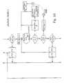
- FIG. 5is a perspective and schematic view illustrating the application of the first embodiment of the portable infusion pump unit illustrated in FIGS. 1-4 in a stationary charger and fixation system for providing a stationary infusion pump system,
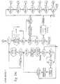
- FIG. 6is a diagrammatic view of a first part of the electronic circuitry of the first embodiment of the portable infusion pump unit illustrated in FIGS. 1-4,
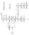
- FIG. 7is a diagrammatic view of a second part of the electronic circuitry of the first embodiment of the portable infusion pump unit illustrated in FIGS. 1-4,
- FIG. 8is a schematic and vertical sectional view of a plunger component included in the first embodiment of the portable infusion pump unit illustrated in FIG. 1,
- FIG. 9is a diagram illustrating the plunger stroke versus time of the plunger component illustrated in FIG. 8 in three alternative operational modes.
- FIGS. 10 a - 10 iare diagrammatic views of 9 alternative operational modes illustrated in flow diagrams.
- a first and presently preferred embodiment of a portable infusion pump unit or apparatusis disclosed designated the reference numeral 10 in its entirety.
- the apparatus 10comprises a housing composed of two shell-like housing parts 12 and 14 constituting a front and rear housing part, respectively.
- the front an rear housing parts 12 and 14are easily disassembled allowing the user to obtain access to the interior of the apparatus for substituting an interior fluid passage component to be described in greater detail below with reference to FIG. 3 constituting a disposable pre-sterilized component which is easily demounted after use and readily replaced prior to use.
- a clip 16From the rear side of the housing part 14 , a clip 16 allowing the apparatus 10 to be fixed to a strap or a belt extends.
- a display 20is provided, comprising two sets of two digits designated the reference numerals 22 and 24 , respectively, for displaying digits representing the time lapsed or the time remaining for infusion operation expressed in minutes and hours, respectively, or seconds and minutes, respectively, or alternatively for displaying digits representing the supply of infusion liquid as expressed in volume per time unit, e.g. ml per hour.
- the display 20further includes a display area 26 for informing the user and/or a person operating the infusion pump apparatus 10 or nursing the user regarding the operational mode of the apparatus, such as standby or running information.
- the display 20includes a number of individual displays positioned above one another and above the standby/running display 26 , one of which is designated the reference numeral 28 .
- These individual displays 28are adapted to display information such as the operational mode, e.g. the information that the apparatus is in a program mode, information regarding whatever information is presented on the two-digit displays 22 , 24 , such as the time remaining for infusion operation, the total time of the infusion operation, whether or not the apparatus is running or is to be started, or any other relevant information to be presented to the user or operator.
- the display 20further includes three individual alarm displays 30 , 32 and 34 for informing the user of the presence of air in the infusion pump circuitry, pressure fault or failure or low battery, respectively.
- a further display 36informs the user or operator of the program sequence presently used or programmed, which program sequence is represented by a digit displaced by a 1-digit display 38 .
- a 3-digit display 40 of the display 20represents information to the user or operator regarding the infusion supply measured in ml per hour or similar relevant measure or ratio.
- a keyboard 42including a set of keys, one of which is designated the reference numeral 44 for allowing the user/operator to control the portable infusion pump unit 10 to perform a specific operation or to program the apparatus by shifting between specific program sequences by increasing a specific digit displayed in a 1-, 2- or 3-digit display, such as the displays 22 , 24 , 38 and 40 , by increasing or reducing the digit in question and by shifting a cursor route relative to the various individual displays of the display 20 for allowing the user/operator to modify the operational mode or shift between various preset programs of the apparatus.
- two terminals 46 and 48are provided for allowing the apparatus 10 to be connected to an electronic charger for supplying electric power to an internal rechargeable battery pack or cell of the apparatus.
- the terminals 46 and 48may alternatively or additionally serve as input/output terminals for establishing communication between the apparatus 10 and an external apparatus or equipment such as an external data logging apparatus or surveillance apparatus or further alternatively for communicating with an external processing unit such as a personal computer or data logging apparatus.
- the apparatus 10may be provided with a conventional input/output terminal such as a conventional RS 232 terminal for establishing communication between the apparatus 10 and an external computer such as the above-mentioned personal computer for processing data produced by the apparatus concerning the operational mode of the apparatus and also supplementary data produced by the apparatus or auxiliary equipment, e.g. data representing the temperature of the infusion liquid supplied by the apparatus 10 or data supplied by additional external measuring or surveillance equipment.
- a conventional input/output terminalsuch as a conventional RS 232 terminal for establishing communication between the apparatus 10 and an external computer such as the above-mentioned personal computer for processing data produced by the apparatus concerning the operational mode of the apparatus and also supplementary data produced by the apparatus or auxiliary equipment, e.g. data representing the temperature of the infusion liquid supplied by the apparatus 10 or data supplied by additional external measuring or surveillance equipment.
- an external computersuch as the above-mentioned personal computer for processing data produced by the apparatus concerning the operational mode of the apparatus and also supplementary data produced by the apparatus or auxiliary equipment, e.
- FIG. 2the interior structure of the portable infusion pump unit or apparatus 10 is disclosed, illustrating the fluid inlet 50 and the fluid outlets 52 and 54 .
- the reference numerals 56 and 58designate two printed circuit boards including the electronic circuitry of the apparatus to be described in further detail below with reference to FIGS. 6 and 7 and including the display, the rechargeable power pack or cell circuitry and the CPU-circuitry of the apparatus controlling the overall operation of the apparatus including the infusion operation.
- the electronic circuitry of the apparatusmay be included in a single printed circuit board or, alternatively, three or more printed circuit boards.
- the internal rechargeable battery pack or cellis designated the reference numeral 60 .
- the internal flow system of the portable infusion pump apparatus 10constituting a disposable and replaceable fluid passage component as mentioned above and including an inlet tube 62 connected to the fluid inlet 50 .
- Two capacitive detectors 64 and 66are mounted on the inlet tube 62 and communicate with the electronic circuitry of the apparatus housed on the printed circuit board 56 and 58 for detecting presence of air bobbles if any in the infusion liquid input to the fluid inlet 50 .
- the inlet tube 62communicates with a first check valve 68 which constitutes an inlet to a pump housing component 70 , in which an internal fluid passage is provided, as will be described in greater details below with reference to FIG.
- a piston type pump 78is provided for transferring the infusion liquid or any other liquid input to the portable infusion pump unit 10 through the fluid inlet 50 to an application site through one of the fluid outlets 52 and 54 .
- the internal flow system of the portable infusion pumpcomprising the fluid inlet 50 , the inlet rube 52 , the capacitive detectors 64 and 66 belonging to the inlet tube 62 , the first check valve 68 , the pump housing component 70 , the output check valve 72 , the outlet tubes 74 and 76 , and the outlets 52 and 54 constitute an integral disposable and replaceable fluid passage component to be described in greater detail below with reference to FIG 13
- the first check valve 58basically comprises a central circular cylindrical housing component 80 from which a frustro-conical top part 81 extends upwardly communicating with the inlet tube 62 and arresting an inlet filter element 82 at the transition between the frustro-conical top part 81 and the cylindrical housing component 80 .
- the cylindrical housing component 80comprises a central annular oral component 84 which is sealed off in the initial or non-active position by a downwardly deflectable sealing membrane 86 .
- the membrane 86is forced downwardly allowing liquid to pass through the central aperture of the central annular component 84 and further through apertures 87 provided offset relatively to the centre of the sealing membrane 86 .
- the first check valve 68communicates with an inlet passage 88 of the pumping house component 70 terminating in an inner chamber defined within an upwardly protruding annular top housing component 90 in which a reciprocating plunger 94 of the piston pump 78 is movable in the direction to and from an abutting pin 96 which separates the inlet passage 88 from an outlet passage 98 .
- the interspace between the reciprocating plunger of the piston pump 78 and the inner surface of the annular top housing component 90is sealed by means of a highly flexible sealing gasket 92 .
- the outlet passage 98communicates with the above described second check valve 72 which is basically of a configuration similar to and functioning as a check valve similar to the above described first check valve 58 , however differing from the above described first check valve in that the second check valve 72 does not include any filter element similar to the filter element 82 .
- the second check valve 72includes a downwardly protruding annular housing part 100 , which is cast integral with the pumping house component 70 , fulfilling, however, the same purpose as the above described annular housing part 80 of the first check valve.
- a sealing membrane 102 similar to the above described sealing member 86is received, which includes apertures 103 similar to the apertures 87 described above.
- the sealing membrane 102communicates with a conical bore 99 communicating with the outlet passage 98 for sealing off communication from the outlet passage 98 , through the conical bore 99 to the outlet tube 74 provided the sealing membrane 102 rests against an abutting lower surface defining the lower boundary of the conical bore 99 .
- the pumping operation of the portable infusion pump unit 10is established as follows. Initially, the first check valve 68 and the second check valve 72 are in their initial and sealing positions. It is also assumed that liquid is present within the inlet tube 62 within the inlet passage 88 and the outlet passage 98 and also within the outlet tube 74 .
- the piston pump 78is activated through the supply of an electric signal such as an alternating electric signal or a pulsed signal causing a solenoid within the piston pump to move the reciprocating plunger 94 upwardly or downwardly.
- the piston pump 78is preferably, as will be described in greater detail below with reference to FIG.
- a piston pumpin which the plunger 94 is biassed by means of a spring towards the exterior in relation to the housing of the piston pump and, consequently, downwardly in relation to the orientation of the piston pump 78 shown in FIG. 3 .
- the piston pumpincludes a bi-stable solenoid cooperating with the biassing spring of the piston pump for producing a controlled movement on the one hand generating adequate activation of the check valves 68 and 72 and at the same time preventing the generation of excessive pressure fluctuations within the pumping house component 70 .
- the relative vacuum within the outlet passage 98creates a relative vacuum above the sealing membrane 102 which is biassed so as to prevent free flow through the second check valve 72 urging or forcing the sealing membrane into sealing off and abutting engagement with a wall part circumferentially encircling and defining the conical bore 99 , and consequently preventing liquid from being transferred from the outlet passage 98 to the outlet tube 74 .
- the first check valve 68is activated and caused to open whereas the second check valve 72 is blocked.
- the rate of transfer and consequence the flow of liquid from the outlet tube 74is controlled by the rate of operation of the piston pump 78 as an increased frequency of reciprocating the reciprocating plunger 94 increases the velocity of flow of fluid or liquid from the inlet tube 62 to the outlet tube 74 .
- a bypass valvecomprising a sealing membrane 104 which is acted upon by a central stem element 106 of a turnable knob 108 so as to force the sealing membrane 104 into sealing off and abutting engagement with a conical bore 105 provided above and in registration with the above described conical bore 99 .
- the bypass valveis not in operation.
- the sealing membrane 104is raised from its sealing off and abutting engagement with the conical bore 105 as the knob 108 is rotated for causing elevation of the actuator stem 106 , communication from the outlet passage 98 is established through a bypass passage 110 , bypassing the communication from the outlet passage 98 through the conical passage 99 for allowing fluid to flow from the outlet passage 98 through the bypass passage 110 and further through the apertures 103 of the sealing membrane 102 which is consequently not functioning as the bypass valve is in operation.
- the piston pump 78which may constitute a replaceable component of the portable infusion pump unit or apparatus 10 , may provide a specific stroke and, consequently, a specific flow volume per stroke. Therefore, the piston pump 78 is preferably provided with a switch or actuator cooperating with a switch of the electronic circuitry of the apparatus for informing the microprocessor of the electronic circuitry of the apparatus of the type of piston pump included within the apparatus at present.
- the technique of providing information to the microprocessor concerning the type of piston pump included within the apparatus at presentmay be established by means of numerous techniques well-known in the art per se such as by means of code switches, optic capacitive or inductive readers, or simply by means of a feedback circuit monitoring the work rate of the piston pump.
- an inlet tube 112is shown establishing communication from the inlet tube 62 through the fluid inlet 50 not shown in FIG. 3, however, shown in FIG. 2 from an infusion bag 114 which may constitute an infusion bag including an infusion liquid simply constituting physiological liquid or additionally or alternatively a drug suspended in any appropriate liquid, or alternatively blood plasma.
- the outlet from the outlet tube 74 of the portable infusion pump unit 10 shown in FIG. 4is connected to an outlet tube 116 through the fluid outlet 54 , not shown in FIG. 3, however, shown in FIG. 2, which external outlet tube 116 communicates with a cannular assembly 118 of a basically conventional structure.
- the inlet tube 112 and the outlet cube 116may constitute separate inlet and outlet tubes to be connected to the infusion pump unit 10 through the inlet and outlet 50 and 52 or, alternatively, 54 , respectively.
- the inlet tube 112 and the outlet tube 116constitute integral components of the disposable and replaceable fluid passage component illustrated in FIG. 3, which fluid passage component is cooperating with and activated by means of the piston pump 78 .
- the infusion bag 114may be configurated and housed within a container component which is configurated so as to allow the infusion bag 114 to be received and supported on top of the infusion pump unit or apparatus 10 as the above-mentioned receiver is simply connected to and supported by the housing of the portable infusion unit or apparatus 10 .
- FIG. 4The infusion of liquid from the infusion bag 104 is further illustrated in FIG. 4, in which the portable infusion pump 10 is received and fixed relative to an individual 120 by means of a belt or strap 122 on which the infusion bag 114 is further fixated.
- FIG. 4the external inlet tube 112 , the external outlet tube 116 and the cannular assembly 118 are also illustrated.
- FIG. 5the above described first and presently preferred embodiment of the portable infusion pump unit or apparatus 10 is shown in duplicate received within a stationary receptor 140 in which a plurality of receptor compartments 142 are defined.
- Each of the receptor compartments 142is provided with a set of charger terminals for establishing electrical conductive communication with the charger terminal 46 and 48 of the apparatus or unit 10 received within the receptor compartment 140 in question for charging the internal rechargeable battery pack or cell of the apparatus or unit through the supply of electric energy from a mains power supply unit of the receptor assembly 140 which mains supply power supply unit receives electric power through a coiled mains supply wire 148 terminating in a mains plug 150 which is received in a mains AC outlet socket 152 .
- the receptor assembly 140further includes a set of indicator lamps 144 and 146 . Provided none of the indicator lamps 144 and 146 corresponding to a specific receptor compartment 142 are turned off, the indication informs the user or operator that no charging is taking place in the receptor compartment in question. Provided a portable infusion pump unit is received within a specific receptor compartment 142 , one of the lamps 144 and 146 corresponding to the receptor compartment is turned off, one of which informs the user or operator that the protable infusion pump unit in question is to be recharged, or alternatively the other lamp is turned on informing the user or operator that the portable infusion pump unit in question is fully charged and ready for use. Alternative information display modes, such as flashing of lamps for informing malfunction in the rechargeable battery pack or cell of the portable infusion pump is of course also readily deduceable.
- FIGS. 6 and 7the electronic circuitry of the above described first and presently preferred embodiment of the portable infusion pump unit 10 according to the present invention is shown.
- a first part of the electronic circuitryis shown, which part further includes three subsections 154 , 156 and 158 .
- the subsection 154constitutes a driver section for driving the piston pump 78 and receives an oscillating driver signal through two terminals e and f which are supplied through a set of gates 176 , 178 , 180 , 182 , 184 and 186 to gate terminals of respective power MOS-FETs 160 , 162 , 172 and 174 , the source and drain terminals of which are protected through protective diodes 164 , 166 , 168 and 170 , respectively.
- the power MOS-FETs 160 , 162 , 172 and 174constitute a complementary bridged driver circuit.
- the second subsection 156constitutes an alarm section in which a piezoelectric alarm 188 is included.
- An alarm signalis received on a terminal d and input to a NAND gate 200 which is connected in a auto-feedback mode through a resistor 196 and a capacitor 198 and the output of which is connected to two driver gates 190 and 192 one of which is further in a complementary operational mode supplied through a NAND gate 194 .
- the third subsection 158comprises two detector circuits each including two sets of capacitive detectors 64 , 66 and 202 , 204 , respectively.
- the capacitative detectors 64 and 66serve the purpose of detecting the presence of any air bobbles within the inlet tube 62 of the portable infusion pump unit 10
- the capacitive detectors 202 and 204serve the purpose of monitoring the position and the movement of the plunger 94 of the piston pump 78 .
- the detector circuits included in the third subsection 158further comprise a gate 210 receiving a control signal from the central CPU of the apparatus to be described below with reference to FIG.
- the first detector circuitfurther comprises a capacitor 216 and the second detector section similarly comprises a capacitor 252 .
- the capacitive detectors 202 and 204together constitute a capacitor which is connected in a series configuration with the capacitor 212 and, consequently, constitutes a capacitive attenuator in relation to the control signal output from the gate 210 .
- the attenuation of the control signal output from the gate 210is detected by a gate 220 constituted by an inverter which is connected to the node of the capacitor 212 and the capacitor constituted by the capacitive detectors 202 and 204 through the capacitor 216 .
- the capacitive detectors 202 and 204constitute a variable capacitor serving as a detector element.
- the reactants of the variable capacitor constituted by the capacitive detectors 202 and 204is low.
- the capacitive detectors 202 and 204are spaced apart producing a larger reactant.
- the amplitude of the signal detected by the inverter 220may be altered by means of a resistive attenuator comprising a series configuration of a variable resistor 218 and a fixed resistor 214 .
- the output of the inverter 220is connected through a capacitor 222 to a conventional AM detector circuit comprising a capacitor 226 , a resistor 228 and to diodes 230 and 232 .
- the AM detector circuitis of a configuration commonly used within AM radio detectors.
- the AM detector circuitis connected to a further inverter 246 supplying the demodulated output signal generated by the AM detector circuit to the central CPU of the electronic circuitry to be described below with reference to FIG. 7 .
- the second detector circuit part of the third subsection 158similarly comprises a capacitor 252 corresponding to the capacitor 216 described above for presenting a signal to the input of a further inverter 242 corresponding to the inverter 220 described above which signal is generated by the variable attenuator comprising the series configuration of the capacitor 250 and the capacity detectors 64 and 66 which together constitute a viable capacitor the reactance of which is low provided liquid is present within the inlet tube 62 and the capacitance of which is high provided air bubbles or air is present within the inlet tube 62 .
- the second detector circuitcomprises a set of resistors 248 and 256 constituting a fixed and a variable resistor, respectively.
- the output of the gate or inverter 242is supplied to an AM detector circuit through a capacitor 224 which AM detector circuit comprises two diodes 234 and 236 corresponding to the diodes 232 and 230 , respectively, described above, a resistor 238 corresponding to the resistor 228 described above and a capacitor 240 corresponding to the capacitor 216 described above.
- the output of the AM detector circuitis connected to a further gate or inverter 254 which supplies a control signal representing the presence of air or alternatively liquid within the inlet tube 62 to the central CPU of the electronic circuitry to be described below with reference to FIG. 7 .
- the two detector circuit parts of the third subsection 158are basically identical and a common resistive voltage divisor comprising two resistors 258 and 260 are included in the third subsection 158 for defining a preset voltage level above ground, however the positive supply voltage and representing the virtual series voltage level of the detector circuit part.
- the node of the resistors 258 and 260is AC shunted by means of a capacitor 254 .
- the positive voltage defined by the voltage divisor comprising the resistors 258 and 260also serve the purpose of biasing the two detector circuit parts including the gates 220 and 242 , respectively.
- the above described resistors shunting the capacitors constituted by the capacitive detectors 202 , 204 and 64 , 66also serve the purpose of decoupling any static positive and negative voltage generated across the variable capacitors constituted by the capacitive detectors 202 204 , and 64 , 66 , respectively.
- the resistor 214 and 248 of the first detector circuit part and the second detector circuit part, respectivelyserve the purpose of providing static decoupling of the variable capacitors of the detector circuit part in question.
- the variable resistors 218 and 256serve the dual purpose of providing sensitivity adjustment facility and of transferring the virtual zero level or bias voltage to the inputs of the gates 220 and 242 , respectively.
- the detector circuit partsinitially provide a differentiation of the control signal input to the detector circuit part in question and thereupon provides an variable attenuation of the input signal. The variable attenuation of the differential input signal is detected by means of the individual detector circuit part.
- FIG. 7a second part of the electronic circuitry is shown constituting the central CPU and display section.
- the second part of the electronic circuitrycomprises a CPU 262 including integral display driver circuitry for driving an electronic block 264 constituting the display 20 described above with reference to FIG. 1 .
- the CPU 262is connected to peripheral components constituting the supply and clock driver circuitry of the CPU. Consequently, the CPU 262 is connected to a crystal 278 generating the clock frequency of the CPU and the basic control frequency of the overall apparatus. Furthermore, the CPU 262 is connected to a voltage regulator circuit 300 which receives a voltage across input terminals 306 , 308 which are decoupled by a capacitor 302 .
- An output terminal of the voltage regulator block 300is connected to a capacitor 298 defining the positive supply rail of the overall circuitry.
- the voltage regulator block 300is further connected to a comparator circuit constituted by an operation amplifier 290 which is connected with peripheral resistors 292 , 294 & 296 for supplying a reference signal representing the state of the battery supply or the rechargeable battery package or cell of the apparatus which signal is input to the CPU 262 for informing the CPU of low battery state of the rechargeable pack or cell.
- the CPUalso generates the signals constituting control signals which are supplied to the above described first part of the electronic circuitry which control signals are supplied on the terminals a, d, e & f and receives control signals on the terminals b & c from the above described first part of the electronic circuitry of the apparatus.
- the electronic circuitry per seis constituted by a microprocessor based technique well known in the art per se. Reference is made to the below example in which the individual components of the electronic circuitry are identified.
- the piston pump 78is shown in greater details.
- the piston pump 78centrally includes a movable magnetic core 77 which at its lower end is connected to the plunger 94 and at its upper end connected to the capacitive detector 202 which cooperates with the attenuated capacitive detector 204 in the variable capacitive detector circuit described above with reference to FIG. 6 .
- the movable magnetic core 77is housed within a magnetic circuit comprising a permamagnet 310 and a solenoid coil 312 .
- the movable magnetic core 77is further acted upon by a bias spring 314 which serves the purpose of forcing the movable magnetic core 77 to its bottom position.
- the magnetic circuitcomprising the permamagnet 310 and the solenoid coil 312 cooperates with the movable magnetic core 77 by means of a magnetic conductive yoke 322 which magnetic circuit also includes the movable magnetic core 77 .
- the magnetic circuitfurther includes a top pole piece including two separate segments 316 and 318 which are internally mechanically stationary by means of an O-ring 320 .
- the solenoid coil 312is energized, the movable magnetic core 77 is moved upwardly causing the magnetic circuit to be shorted.
- the bias spring 314causes the movable magnetic core 77 to move downwardly as the magnetic circuit is opened.
- the reference numeral 95designates an air cap between the lower end of the plunger 94 through which air gap the plunger 94 acts on the piston of the piston pump 78 and more precisely the piston acting on the flexible sealing gasket 92 also shown in FIG. 3 .
- the air gap 95on the one hand allows the disposable and turnal?? flow system of the portable infusion pump to be removed and replaced provided the infusion unit 10 is shifted from one patient or person to another and on the other hand allow the plunger 94 to start moving after deenergizing the solenoid coil 312 before the motion of the plunger 94 is transferred into a pumping operation within the internal flow system of the infusion pump as will be illustrated in greater details in FIG. 9 .
- FIG. 9a diagram is known illustrating the dependency between the signal output by the inverter 246 to the central microprocessor of the electronic circuitry and time for three states of operation of the piston pump.
- a curve Aillustrates the normal operational state of the piston pump in which state the inlet tube 62 is unblocked and filled with infusion liquid and in which the output tube 74 is also unblocked.
- a curve Brepresents an operational mode in which the outlet tube 74 is blocked and a curve C illustrates an operational mode in which the inlet tube 62 is blocked.
- the bias spring 314causes the plunger 94 to move downwardly. It is to be realized that a certain clearance of the order of 0.5 mm exists between the position of the plunger in which the solenoid coil 312 is energized and the position in which the plunger activates or engages with the top housing component 90 of the pumping house component 70 .
- the capacitive detectors 202 and 204are in the position positioned close to one another producing a low reactance capacitance as described above with reference to FIG. 6 .
- the capacitance of the capacitor constituted by the capacitive detectors 202 and 204is high.
- the downwardly motion of the plunger 94is subjected to certain mechanical resistance causing a certain delay in the shift of capacitance of the capacitor constituted by the capacitive detectors 202 and 204 .
- the plungermoves fairly rapidly downwardly causing the generation of the response output from the inverter 246 corresponding to the curve A illustrated in FIG. 9 .
- the inlet tube 62is blocked, vacuum is generated within the inlet tube, and the plunger 94 may move downwardly without any mechanical resistance causing the capacitance of the capacitor constituted by the capacitive detectors 202 and 204 to raise rapidly as indicated by the curve C in FIG. 9 .
- the outlet tube 74is blocked, the piston is exposed to extreme resistance preventing the plunger from being moved beyond a specific position as the infusion liquid is non-compressible.
- the response output from the inverter 246therefore fails to raise above a specific level as indicated by the curve B in FIG. 9 .
- the central microprocessor of the electronic circuitry of the infusion pump unit 10monitors the response output from the inverter 246 as the microprocessor after a period of time T 1 monitors the response output from the inventor or gate 246 .
- T 1monitors the response output from the inventor or gate 246 .
- the microprocessordetects a maximum response corresponding to the level V 1 +V 2 indicated along the ordinate axis in FIG. 9 .
- the microprocessorwaits until the lapse of a further period of time T 2 until the time T 3 at which time the microprocessor detects whether or not the response has increased above the level or reached the level V 2 indicated that the piston pump is operating in its normal operational mode.
- the microprocessorcarries out a further detection at time T 4 at which time the microprocessor provided the response still has not reached the level V 2 determines that the outlet tube 74 is blocked.
- the level V 4corresponds to the response supplied from the inverter 246 as the plunger 94 is moved at distance corresponding to the above described clearance.
- FIGS. 10A-10Ispecific flow diagrammatic illustrations of a total of 9 different operational modes of the infusion pump unit or apparatus are shown which flow diagrammatic charge are believed to be self-explanatory and therefore need no further comments or description.
- the above described presently preferred and first embodiment of the portable infusion pump cell or apparatus 10was implemented in a prototype embodiment by the below components.
- the housingwas composed of two ABS housing parts 12 and 14 .
- the terminals 46 and 48were constituted by non-insulated female plugs allowing electrical connection to corresponding plugs or cooperating male plugs.
- the display 20was implemented by individual display elements.
- the keyboard 42was implemented by individual pushbutton keys.
- Power MOS-FET 160was a IRF 7304 .
- the power MOS-FET 162was an IRF 7301 .
- the power MOS-FET 172was a IRF 7304 .
- the power MOS-FET 174was a IRF 7301 .
- the diodes 164 , 166 , 168 & 170were constituted by individual shottky-diodes.
- the inverters 176 , 178 , 180 & 182were constituted by single integrated circuits of the type 4504 .
- the NAND gates 184 & 186were implemented by a 4093.
- the inverters 190 & 192were inverters implemented by a 4504 .
- the NAND gates 194 & 200were 4093.
- the resistor 196was a IM.
- the capacitor 198was 470 pF.
- the inverters 210 , 220 , 242 , 244 & 246were 40106.
- the diodes 230 , 232 , 234 , 236were IN4148.
- the capacitor 212was 2.7 pF.
- the resistor 214was IM.
- the adjustable resistor 218was 10K.
- the capacitor 216was 60 pF.
- the capacitor 22was 10 nF.
- the capacitor 224was 10 nF.
- the electrolytic capacitor 226was 47 nF.
- the resistor 228was 1 M ⁇ .
- the resistor 238was 1 M ⁇ .
- the electrolytic capacitor 240was 47 nF.
- the resistor 248was 1 M ⁇ .
- the capacitor 250was 2.7 pF.
- the capacitor 252was 100 pF.
- the electrolytic capacitor 254was 2.2 ⁇ F.
- the adjustable resistor 256was 1 k ⁇ .
- the resistors 258 and 260were 1 M ⁇ .
- the diode 266was IN4142.
- the resistor 268was 1 k ⁇ .
- the resistor 270was 47 k ⁇
- the resistor 274was 47 k ⁇ .
- the resistor 276was 47 k ⁇ .
- the clock crystal 278was 5 MHz.
- the capacitor 280was 30 pF.
- the capacitor 282was 30 pF.
- the resistor 284was 2.4 M ⁇ .
- the resistor 286was 10 k ⁇ .
- the operational amplifier 290was M931.
- the resistor 292was 4.3 M ⁇ .
- the resistor 294was 1.2 M ⁇ .
- the resistor 296was 10 k ⁇ .
- the electrolytic capacitor 298was 2.2 ⁇ F.
- the voltage regulator block 300was in integrated electronic circuit of the type M 883.
- the electrolytic capacitor 302was 2.2 ⁇ F.
- the electrolytic capacitor 304was 2.2 ⁇ F.
- the infusion pump system and also the infusion pump unitmay be modified in numerous ways obvious to a person having ordinary skill in the art without deviating from the scope of the present invention.
- the electronic circuitry of the infusion pump unitmay be modified in numerous ways by e.g. combining or separating various components of the electronic circuitry such as through combining the electronic clock circuits of the electronic circuitry into a single clock circuitry or by including individual or respective electronic clock circuits of the individual blocks of the electronic circuitry.
- the subsection 158 illustrated in FIG. 6may comprise a separate clock circuitry generating a clock signal substituting the clock signal as illustrated in FIG.
- subsection 154may be modified by including a power MOSFET protecting circuitry eliminating the risk of simultaneously triggering the power MOSFETs of the two branches at the same time and thereby eliminating the risk of destroying the power MOSFET unintentionally.
- the power MOSFETsmay be substituted by planar power transistors well known in the art or any other power driver circuit.
- a further modification of the above described preferred and advantageous embodiment of the infusion pumpmay be established by including a purge function in the apparatus allowing the user to manually activate the infusion pump for providing an increased infusion dose.
Landscapes
- Health & Medical Sciences (AREA)
- Vascular Medicine (AREA)
- Engineering & Computer Science (AREA)
- Anesthesiology (AREA)
- Biomedical Technology (AREA)
- Heart & Thoracic Surgery (AREA)
- Hematology (AREA)
- Life Sciences & Earth Sciences (AREA)
- Animal Behavior & Ethology (AREA)
- General Health & Medical Sciences (AREA)
- Public Health (AREA)
- Veterinary Medicine (AREA)
- Infusion, Injection, And Reservoir Apparatuses (AREA)
Abstract
Description
Claims (26)
Applications Claiming Priority (3)
| Application Number | Priority Date | Filing Date | Title |
|---|---|---|---|
| DK120697 | 1997-10-23 | ||
| DK120697 | 1997-10-23 | ||
| PCT/DK1998/000457WO1999021596A1 (en) | 1997-10-23 | 1998-10-21 | An infusion pump system and an infusion pump unit |
Related Parent Applications (1)
| Application Number | Title | Priority Date | Filing Date |
|---|---|---|---|
| PCT/DK1998/000457ContinuationWO1999021596A1 (en) | 1997-10-23 | 1998-10-21 | An infusion pump system and an infusion pump unit |
Publications (1)
| Publication Number | Publication Date |
|---|---|
| US6270478B1true US6270478B1 (en) | 2001-08-07 |
Family
ID=8102170
Family Applications (1)
| Application Number | Title | Priority Date | Filing Date |
|---|---|---|---|
| US09/545,741Expired - LifetimeUS6270478B1 (en) | 1997-10-23 | 2000-04-03 | Infusion pump system and an infusion pump unit |
Country Status (8)
| Country | Link |
|---|---|
| US (1) | US6270478B1 (en) |
| EP (1) | EP1024844B1 (en) |
| AT (1) | ATE293465T1 (en) |
| AU (1) | AU9621898A (en) |
| BR (1) | BR9812969A (en) |
| CA (1) | CA2301534A1 (en) |
| DE (1) | DE69829869D1 (en) |
| WO (1) | WO1999021596A1 (en) |
Cited By (106)
| Publication number | Priority date | Publication date | Assignee | Title |
|---|---|---|---|---|
| US20030130645A1 (en)* | 2001-12-03 | 2003-07-10 | Tandem Medical, Inc. | Devices and methods for delivery of medically appropriate fluids |
| WO2003055538A1 (en)* | 2001-12-24 | 2003-07-10 | Dong Kyu Jin | Infusion pump system for infusion of iduronate-2-sulfatase relieving hunter syndrome |
| US20030212364A1 (en)* | 1998-08-18 | 2003-11-13 | Medtronic Minimed, Inc. | External infusion device with remote programming, bolus estimator and/or vibration alarm capabilities |
| US20040254527A1 (en)* | 2003-06-10 | 2004-12-16 | Vitello Christopher John | Apparatus and methods for administering bioactive compositions |
| JP2005006709A (en)* | 2003-06-16 | 2005-01-13 | Naigai Kasei Kk | Medical cap |
| US20050245899A1 (en)* | 2003-10-28 | 2005-11-03 | Swisher David R | Dual purpose adapter |
| US20060021419A1 (en)* | 2004-05-28 | 2006-02-02 | Cassidy David E | Gas detection in an intravenous fluid delivery system |
| US20060031099A1 (en)* | 2003-06-10 | 2006-02-09 | Vitello Christopher J | System and methods for administering bioactive compositions |
| US20060122559A1 (en)* | 2002-10-28 | 2006-06-08 | Benedict Shia | Automatic valve |
| US20060129092A1 (en)* | 2002-10-28 | 2006-06-15 | Sherwood Services Ag | Single lumen adapter for automatic valve |
| WO2006089958A1 (en) | 2005-02-25 | 2006-08-31 | Novo Nordisk A/S | Pump assembly with safety valve |
| US20060211986A1 (en)* | 2005-03-17 | 2006-09-21 | Smisson Hugh F Iii | Fluid heat exchanger and airtrap |
| US20070021733A1 (en)* | 2003-10-21 | 2007-01-25 | Novo Nordisk A/S | Internal fluid connector |
| US20070049865A1 (en)* | 2003-08-01 | 2007-03-01 | Novo Nordisk A/S | Retraction means for transcutaneous device |
| US20070166181A1 (en)* | 2002-03-14 | 2007-07-19 | Billy Nilson | Ambulatory infusion membrane pump |
| US7278983B2 (en) | 2002-07-24 | 2007-10-09 | Medtronic Minimed, Inc. | Physiological monitoring device for controlling a medication infusion device |
| US20080051716A1 (en)* | 2006-08-23 | 2008-02-28 | Medtronic Minimed, Inc. | Infusion pumps and methods and delivery devices and methods with same |
| US20080156476A1 (en)* | 2005-03-17 | 2008-07-03 | Smisson-Cartledge Biomedical Llc | Heat Exchange System For A Pump Device |
| US20080167641A1 (en)* | 2005-05-13 | 2008-07-10 | Novo Nordisk A/S | Medical Device Adapted To Detect Disengagement Of A Transcutaneous Device |
| US20090076451A1 (en)* | 2005-01-24 | 2009-03-19 | Nova Nordisk A/S | Medical Device with Protected Transcutaneous Device |
| US20090099509A1 (en)* | 2002-07-24 | 2009-04-16 | Medtronic Minimed, Inc. | System for Providing Blood Glucose Measurements to an Infusion Device |
| US7520871B2 (en) | 2002-08-12 | 2009-04-21 | Lma North America, Inc | System and method for tension-activated fluid control |
| US7530968B2 (en) | 2003-04-23 | 2009-05-12 | Valeritas, Inc. | Hydraulically actuated pump for long duration medicament administration |
| US7615007B2 (en) | 2006-10-04 | 2009-11-10 | Dexcom, Inc. | Analyte sensor |
| US7640048B2 (en) | 2004-07-13 | 2009-12-29 | Dexcom, Inc. | Analyte sensor |
| US7713241B2 (en) | 1999-09-29 | 2010-05-11 | Smisson-Cartledge Biomedical L.L.C. | Rapid infusion system |
| US7783333B2 (en) | 2004-07-13 | 2010-08-24 | Dexcom, Inc. | Transcutaneous medical device with variable stiffness |
| EP2077129A4 (en)* | 2006-10-23 | 2011-01-26 | Sun Medical Scient Shanghai Co Ltd | Intelligent remote-controlled portable intravenous injection and transfusion system |
| US7885697B2 (en) | 2004-07-13 | 2011-02-08 | Dexcom, Inc. | Transcutaneous analyte sensor |
| US7914499B2 (en) | 2006-03-30 | 2011-03-29 | Valeritas, Inc. | Multi-cartridge fluid delivery device |
| US7922462B2 (en) | 2004-03-30 | 2011-04-12 | Novo Nordisk A/S | Actuator system comprising lever mechanism |
| US7981085B2 (en) | 2003-05-08 | 2011-07-19 | Novo Nordisk A/S | Internal needle inserter |
| US8029469B2 (en) | 2003-05-08 | 2011-10-04 | Novo Nordisk A/S | External inserter for transcutaneous device |
| US8105269B2 (en) | 2008-10-24 | 2012-01-31 | Baxter International Inc. | In situ tubing measurements for infusion pumps |
| US8137083B2 (en) | 2009-03-11 | 2012-03-20 | Baxter International Inc. | Infusion pump actuators, system and method for controlling medical fluid flowrate |
| US8275438B2 (en) | 2006-10-04 | 2012-09-25 | Dexcom, Inc. | Analyte sensor |
| US8287495B2 (en) | 2009-07-30 | 2012-10-16 | Tandem Diabetes Care, Inc. | Infusion pump system with disposable cartridge having pressure venting and pressure feedback |
| US8287453B2 (en) | 2003-12-05 | 2012-10-16 | Dexcom, Inc. | Analyte sensor |
| US8290559B2 (en) | 2007-12-17 | 2012-10-16 | Dexcom, Inc. | Systems and methods for processing sensor data |
| US8298142B2 (en) | 2006-10-04 | 2012-10-30 | Dexcom, Inc. | Analyte sensor |
| US8364231B2 (en) | 2006-10-04 | 2013-01-29 | Dexcom, Inc. | Analyte sensor |
| US8364230B2 (en) | 2006-10-04 | 2013-01-29 | Dexcom, Inc. | Analyte sensor |
| US8382447B2 (en) | 2009-12-31 | 2013-02-26 | Baxter International, Inc. | Shuttle pump with controlled geometry |
| US8396528B2 (en) | 2008-03-25 | 2013-03-12 | Dexcom, Inc. | Analyte sensor |
| US8408421B2 (en) | 2008-09-16 | 2013-04-02 | Tandem Diabetes Care, Inc. | Flow regulating stopcocks and related methods |
| US8417312B2 (en) | 2007-10-25 | 2013-04-09 | Dexcom, Inc. | Systems and methods for processing sensor data |
| US8418287B2 (en)* | 2001-05-25 | 2013-04-16 | Hill-Rom Services, Inc. | Bed side rail having cavity for infusion unit |
| US8425416B2 (en) | 2006-10-04 | 2013-04-23 | Dexcom, Inc. | Analyte sensor |
| US8425417B2 (en) | 2003-12-05 | 2013-04-23 | Dexcom, Inc. | Integrated device for continuous in vivo analyte detection and simultaneous control of an infusion device |
| US8447376B2 (en) | 2006-10-04 | 2013-05-21 | Dexcom, Inc. | Analyte sensor |
| US8449464B2 (en) | 2006-10-04 | 2013-05-28 | Dexcom, Inc. | Analyte sensor |
| US8478377B2 (en) | 2006-10-04 | 2013-07-02 | Dexcom, Inc. | Analyte sensor |
| US8557179B2 (en) | 2007-10-31 | 2013-10-15 | Novo Nordisk A/S | Non-porous material as sterilization barrier |
| US8562528B2 (en) | 2006-10-04 | 2013-10-22 | Dexcom, Inc. | Analyte sensor |
| US8562558B2 (en) | 2007-06-08 | 2013-10-22 | Dexcom, Inc. | Integrated medicament delivery device for use with continuous analyte sensor |
| US8567235B2 (en) | 2010-06-29 | 2013-10-29 | Baxter International Inc. | Tube measurement technique using linear actuator and pressure sensor |
| US8591457B2 (en) | 2005-08-10 | 2013-11-26 | Alza Corporation | Method for making a needle-free jet injection drug delivery device |
| US8626257B2 (en) | 2003-08-01 | 2014-01-07 | Dexcom, Inc. | Analyte sensor |
| US8650937B2 (en) | 2008-09-19 | 2014-02-18 | Tandem Diabetes Care, Inc. | Solute concentration measurement device and related methods |
| WO2014081411A1 (en) | 2012-11-20 | 2014-05-30 | West Pharmaceuticals Services, Inc. | System and method to distribute power to both an inertial device and a voltage sensitive device from a single current limited power source |
| US8740851B2 (en) | 2003-05-08 | 2014-06-03 | Novo Nordisk A/S | Integrated package |
| WO2014166157A1 (en)* | 2013-04-10 | 2014-10-16 | 中国人民解放军第四军医大学 | Miniature portable multifunctional infusion device |
| US8886273B2 (en) | 2003-08-01 | 2014-11-11 | Dexcom, Inc. | Analyte sensor |
| US8986253B2 (en) | 2008-01-25 | 2015-03-24 | Tandem Diabetes Care, Inc. | Two chamber pumps and related methods |
| WO2015102152A1 (en)* | 2013-12-31 | 2015-07-09 | 수상에스티(주) | Portable aqueous solution-contactless aqueous solution container state detector and system for exchanging and managing aqueous solution container by using same |
| US9089642B2 (en) | 2011-06-20 | 2015-07-28 | Renaudia Medical, Llc | Distributed medication delivery system and method having autonomous delivery devices |
| US9089636B2 (en) | 2004-07-02 | 2015-07-28 | Valeritas, Inc. | Methods and devices for delivering GLP-1 and uses thereof |
| US9135402B2 (en) | 2007-12-17 | 2015-09-15 | Dexcom, Inc. | Systems and methods for processing sensor data |
| US9173992B2 (en) | 2006-03-13 | 2015-11-03 | Novo Nordisk A/S | Secure pairing of electronic devices using dual means of communication |
| US9399094B2 (en) | 2006-06-06 | 2016-07-26 | Novo Nordisk A/S | Assembly comprising skin-mountable device and packaging therefore |
| US9649436B2 (en) | 2011-09-21 | 2017-05-16 | Bayer Healthcare Llc | Assembly method for a fluid pump device for a continuous multi-fluid delivery system |
| US9962486B2 (en) | 2013-03-14 | 2018-05-08 | Tandem Diabetes Care, Inc. | System and method for detecting occlusions in an infusion pump |
| US9986942B2 (en) | 2004-07-13 | 2018-06-05 | Dexcom, Inc. | Analyte sensor |
| US10015931B2 (en) | 2012-12-28 | 2018-07-10 | Elwha Llc | Production of electricity from plants |
| US10015971B2 (en) | 2012-12-28 | 2018-07-10 | Elwha Llc | Articles and methods for administering CO2 into plants |
| US10017392B2 (en) | 2012-12-28 | 2018-07-10 | Elwha Llc | Articles and methods for administering CO2 into plants |
| US10258736B2 (en) | 2012-05-17 | 2019-04-16 | Tandem Diabetes Care, Inc. | Systems including vial adapter for fluid transfer |
| USD854145S1 (en)* | 2016-05-25 | 2019-07-16 | Deka Products Limited Partnership | Apparatus to control fluid flow through a tube |
| US10507319B2 (en) | 2015-01-09 | 2019-12-17 | Bayer Healthcare Llc | Multiple fluid delivery system with multi-use disposable set and features thereof |
| US10556063B2 (en) | 2011-06-20 | 2020-02-11 | Renaudia Medical, Llc | Distributed medication delivery using autonomous delivery device |
| US10610135B2 (en) | 2005-03-10 | 2020-04-07 | Dexcom, Inc. | System and methods for processing analyte sensor data for sensor calibration |
| USD883472S1 (en)* | 2017-12-06 | 2020-05-05 | N.V. Nutricia | Control panel with display for feeding devices |
| US10653834B2 (en) | 2012-06-07 | 2020-05-19 | Tandem Diabetes Care, Inc. | Device and method for training users of ambulatory medical devices |
| US10813577B2 (en) | 2005-06-21 | 2020-10-27 | Dexcom, Inc. | Analyte sensor |
| US10835672B2 (en) | 2004-02-26 | 2020-11-17 | Dexcom, Inc. | Integrated insulin delivery system with continuous glucose sensor |
| US10844970B2 (en) | 2011-12-21 | 2020-11-24 | Deka Products Limited Partnership | Flow meter |
| USD905848S1 (en)* | 2016-01-28 | 2020-12-22 | Deka Products Limited Partnership | Apparatus to control fluid flow through a tube |
| US10876868B2 (en) | 2011-12-21 | 2020-12-29 | Deka Products Limited Partnership | System, method, and apparatus for monitoring, regulating, or controlling fluid flow |
| US10966609B2 (en) | 2004-02-26 | 2021-04-06 | Dexcom, Inc. | Integrated medicament delivery device for use with continuous analyte sensor |
| US10980461B2 (en) | 2008-11-07 | 2021-04-20 | Dexcom, Inc. | Advanced analyte sensor calibration and error detection |
| US11000215B1 (en) | 2003-12-05 | 2021-05-11 | Dexcom, Inc. | Analyte sensor |
| US11246990B2 (en) | 2004-02-26 | 2022-02-15 | Dexcom, Inc. | Integrated delivery device for continuous glucose sensor |
| WO2022072809A1 (en)* | 2020-10-02 | 2022-04-07 | SFC Fluidics, Inc. | Wearable drug infusion device |
| US11331022B2 (en) | 2017-10-24 | 2022-05-17 | Dexcom, Inc. | Pre-connected analyte sensors |
| US11350862B2 (en) | 2017-10-24 | 2022-06-07 | Dexcom, Inc. | Pre-connected analyte sensors |
| US11399745B2 (en) | 2006-10-04 | 2022-08-02 | Dexcom, Inc. | Dual electrode system for a continuous analyte sensor |
| CN114867507A (en)* | 2019-12-23 | 2022-08-05 | 阿西斯特医药系统公司 | Modular Fluid Delivery System |
| US11449037B2 (en) | 2011-12-21 | 2022-09-20 | Deka Products Limited Partnership | System, method, and apparatus for monitoring, regulating, or controlling fluid flow |
| USD964563S1 (en) | 2019-07-26 | 2022-09-20 | Deka Products Limited Partnership | Medical flow clamp |
| US11633133B2 (en) | 2003-12-05 | 2023-04-25 | Dexcom, Inc. | Dual electrode system for a continuous analyte sensor |
| US11738143B2 (en) | 2011-12-21 | 2023-08-29 | Deka Products Limited Partnership | Flow meier having a valve |
| US11744935B2 (en) | 2016-01-28 | 2023-09-05 | Deka Products Limited Partnership | Apparatus for monitoring, regulating, or controlling fluid flow |
| US11771822B1 (en)* | 2019-12-09 | 2023-10-03 | John Imboden | Wearable drug delivery system |
| US11819666B2 (en) | 2017-05-30 | 2023-11-21 | West Pharma. Services IL, Ltd. | Modular drive train for wearable injector |
| US11839741B2 (en) | 2019-07-26 | 2023-12-12 | Deka Products Limited Partneship | Apparatus for monitoring, regulating, or controlling fluid flow |
| US12357767B2 (en) | 2016-08-01 | 2025-07-15 | West Pharma. Services IL, Ltd. | Partial door closure prevention spring |
Families Citing this family (45)
| Publication number | Priority date | Publication date | Assignee | Title |
|---|---|---|---|---|
| SE523272C2 (en)* | 1999-11-15 | 2004-04-06 | Aneo Ab | System for intravenous anesthesia for the control of a drug delivery to a patient |
| AU2003245872A1 (en) | 2002-07-24 | 2004-02-09 | M 2 Medical A/S | An infusion pump system, an infusion pump unit and an infusion pump |
| WO2004056412A2 (en) | 2002-12-23 | 2004-07-08 | M2 Medical A/S | A disposable, wearable insulin dispensing device, a combination of such a device and a programming controller and a method of controlling the operation of such a device |
| CN1726059A (en) | 2002-11-05 | 2006-01-25 | M2医药有限公司 | Disposable wearable insulin dispensing device, combination of the device and a program controller and method for controlling the operation of the device |
| EP1877115A1 (en) | 2005-04-06 | 2008-01-16 | M 2 Medical A/S | An actuator |
| DK1933902T3 (en) | 2005-09-26 | 2015-03-23 | Asante Solutions Inc | Infusion Pump WITH A DRIVE THAT HAVE AN PALLEGEME- AND CONGEST HAGE-COMBINATION |
| US7534226B2 (en) | 2005-09-26 | 2009-05-19 | M2 Group Holdings, Inc. | Dispensing fluid from an infusion pump system |
| US8105279B2 (en) | 2005-09-26 | 2012-01-31 | M2 Group Holdings, Inc. | Dispensing fluid from an infusion pump system |
| US8409142B2 (en) | 2005-09-26 | 2013-04-02 | Asante Solutions, Inc. | Operating an infusion pump system |
| WO2007056592A2 (en) | 2005-11-08 | 2007-05-18 | M2 Medical A/S | Method and system for manual and autonomous control of an infusion pump |
| US7833196B2 (en) | 2007-05-21 | 2010-11-16 | Asante Solutions, Inc. | Illumination instrument for an infusion pump |
| US7981102B2 (en) | 2007-05-21 | 2011-07-19 | Asante Solutions, Inc. | Removable controller for an infusion pump |
| US7892199B2 (en) | 2007-05-21 | 2011-02-22 | Asante Solutions, Inc. | Occlusion sensing for an infusion pump |
| US7717903B2 (en) | 2007-09-06 | 2010-05-18 | M2 Group Holdings, Inc. | Operating an infusion pump system |
| US8287514B2 (en) | 2007-09-07 | 2012-10-16 | Asante Solutions, Inc. | Power management techniques for an infusion pump system |
| US7935076B2 (en) | 2007-09-07 | 2011-05-03 | Asante Solutions, Inc. | Activity sensing techniques for an infusion pump system |
| US8032226B2 (en) | 2007-09-07 | 2011-10-04 | Asante Solutions, Inc. | User profile backup system for an infusion pump device |
| US7959598B2 (en) | 2008-08-20 | 2011-06-14 | Asante Solutions, Inc. | Infusion pump systems and methods |
| US8852152B2 (en) | 2011-02-09 | 2014-10-07 | Asante Solutions, Inc. | Infusion pump systems and methods |
| US8454581B2 (en) | 2011-03-16 | 2013-06-04 | Asante Solutions, Inc. | Infusion pump systems and methods |
| US8808230B2 (en) | 2011-09-07 | 2014-08-19 | Asante Solutions, Inc. | Occlusion detection for an infusion pump system |
| US8454557B1 (en) | 2012-07-19 | 2013-06-04 | Asante Solutions, Inc. | Infusion pump system and method |
| US8454562B1 (en) | 2012-07-20 | 2013-06-04 | Asante Solutions, Inc. | Infusion pump system and method |
| US9427523B2 (en) | 2012-12-10 | 2016-08-30 | Bigfoot Biomedical, Inc. | Infusion pump system and method |
| US20140276536A1 (en) | 2013-03-14 | 2014-09-18 | Asante Solutions, Inc. | Infusion Pump System and Methods |
| CN103083756A (en)* | 2013-01-18 | 2013-05-08 | 郑州瑞宇科技有限公司 | Intelligent insulin pump |
| US9446186B2 (en) | 2013-03-01 | 2016-09-20 | Bigfoot Biomedical, Inc. | Operating an infusion pump system |
| US9457141B2 (en) | 2013-06-03 | 2016-10-04 | Bigfoot Biomedical, Inc. | Infusion pump system and method |
| US9446187B2 (en) | 2013-06-03 | 2016-09-20 | Bigfoot Biomedical, Inc. | Infusion pump system and method |
| US9561324B2 (en) | 2013-07-19 | 2017-02-07 | Bigfoot Biomedical, Inc. | Infusion pump system and method |
| US10569015B2 (en) | 2013-12-02 | 2020-02-25 | Bigfoot Biomedical, Inc. | Infusion pump system and method |
| US9629901B2 (en) | 2014-07-01 | 2017-04-25 | Bigfoot Biomedical, Inc. | Glucagon administration system and methods |
| US10137246B2 (en) | 2014-08-06 | 2018-11-27 | Bigfoot Biomedical, Inc. | Infusion pump assembly and method |
| US9919096B2 (en) | 2014-08-26 | 2018-03-20 | Bigfoot Biomedical, Inc. | Infusion pump system and method |
| US9878097B2 (en) | 2015-04-29 | 2018-01-30 | Bigfoot Biomedical, Inc. | Operating an infusion pump system |
| AU2016385454B2 (en) | 2016-01-05 | 2021-12-16 | Bigfoot Biomedical, Inc. | Operating multi-modal medicine delivery systems |
| US10449294B1 (en) | 2016-01-05 | 2019-10-22 | Bigfoot Biomedical, Inc. | Operating an infusion pump system |
| SG11201805935PA (en) | 2016-01-12 | 2018-08-30 | Infusion Innovations Pty Ltd | Infusion device |
| HK1256995A1 (en) | 2016-01-14 | 2019-10-11 | Bigfoot Biomedical, Inc. | Occlusion resolution in medication delivery devices, systems, and methods |
| USD809134S1 (en) | 2016-03-10 | 2018-01-30 | Bigfoot Biomedical, Inc. | Infusion pump assembly |
| AU2017335762B2 (en) | 2016-09-27 | 2022-03-17 | Bigfoot Biomedical, Inc. | Medicine injection and disease management systems, devices, and methods |
| USD836769S1 (en) | 2016-12-12 | 2018-12-25 | Bigfoot Biomedical, Inc. | Insulin delivery controller |
| EP3500161A4 (en) | 2016-12-12 | 2020-01-08 | Bigfoot Biomedical, Inc. | ALARMS AND WARNINGS FOR MEDICINE DELIVERY DEVICES AND RELATED SYSTEMS AND METHODS |
| USD839294S1 (en) | 2017-06-16 | 2019-01-29 | Bigfoot Biomedical, Inc. | Display screen with graphical user interface for closed-loop medication delivery |
| EP3651647A1 (en) | 2017-07-13 | 2020-05-20 | Bigfoot Biomedical, Inc. | Multi-scale display of blood glucose information |
Citations (8)
| Publication number | Priority date | Publication date | Assignee | Title |
|---|---|---|---|---|
| EP0062974A1 (en) | 1981-04-10 | 1982-10-20 | Parker Hannifin Corporation | Medication injection device |
| US4482347A (en) | 1982-08-12 | 1984-11-13 | American Hospital Supply Corporation | Peristaltic fluid-pumping apparatus |
| US4601707A (en) | 1980-06-03 | 1986-07-22 | Albisser Anthony M | Insulin infusion device |
| US4756706A (en) | 1985-01-23 | 1988-07-12 | American Hospital Supply Corporation | Centrally managed modular infusion pump system |
| US4976687A (en)* | 1987-05-11 | 1990-12-11 | James Martin | Apparatus for controlling the supplying of intravenous fluids |
| US5135485A (en)* | 1991-02-25 | 1992-08-04 | Louis Cohen | Capacitance-type fluid level sensor for i.v. and catheter bags |
| US5211626A (en)* | 1987-05-01 | 1993-05-18 | Product Innovation Holdings Ltd. | Medical infusion apparatus |
| US5632606A (en)* | 1993-11-23 | 1997-05-27 | Sarcos Group | Volumetric pump/valve |
Family Cites Families (1)
| Publication number | Priority date | Publication date | Assignee | Title |
|---|---|---|---|---|
| US5370622A (en)* | 1994-04-28 | 1994-12-06 | Minimed Inc. | Proctective case for a medication infusion pump |
- 1998
- 1998-10-21WOPCT/DK1998/000457patent/WO1999021596A1/enactiveIP Right Grant
- 1998-10-21BRBR9812969-4Apatent/BR9812969A/enunknown
- 1998-10-21EPEP98949957Apatent/EP1024844B1/ennot_activeExpired - Lifetime
- 1998-10-21ATAT98949957Tpatent/ATE293465T1/ennot_activeIP Right Cessation
- 1998-10-21AUAU96218/98Apatent/AU9621898A/ennot_activeAbandoned
- 1998-10-21DEDE69829869Tpatent/DE69829869D1/ennot_activeExpired - Lifetime
- 1998-10-21CACA002301534Apatent/CA2301534A1/ennot_activeAbandoned
- 2000
- 2000-04-03USUS09/545,741patent/US6270478B1/ennot_activeExpired - Lifetime
Patent Citations (8)
| Publication number | Priority date | Publication date | Assignee | Title |
|---|---|---|---|---|
| US4601707A (en) | 1980-06-03 | 1986-07-22 | Albisser Anthony M | Insulin infusion device |
| EP0062974A1 (en) | 1981-04-10 | 1982-10-20 | Parker Hannifin Corporation | Medication injection device |
| US4482347A (en) | 1982-08-12 | 1984-11-13 | American Hospital Supply Corporation | Peristaltic fluid-pumping apparatus |
| US4756706A (en) | 1985-01-23 | 1988-07-12 | American Hospital Supply Corporation | Centrally managed modular infusion pump system |
| US5211626A (en)* | 1987-05-01 | 1993-05-18 | Product Innovation Holdings Ltd. | Medical infusion apparatus |
| US4976687A (en)* | 1987-05-11 | 1990-12-11 | James Martin | Apparatus for controlling the supplying of intravenous fluids |
| US5135485A (en)* | 1991-02-25 | 1992-08-04 | Louis Cohen | Capacitance-type fluid level sensor for i.v. and catheter bags |
| US5632606A (en)* | 1993-11-23 | 1997-05-27 | Sarcos Group | Volumetric pump/valve |
Cited By (251)
| Publication number | Priority date | Publication date | Assignee | Title |
|---|---|---|---|---|
| US20030212364A1 (en)* | 1998-08-18 | 2003-11-13 | Medtronic Minimed, Inc. | External infusion device with remote programming, bolus estimator and/or vibration alarm capabilities |
| US7815602B2 (en)* | 1998-08-18 | 2010-10-19 | Medtronic Minimed, Inc. | External infusion device with remote programming, bolus estimator and/or vibration alarm capabilities |
| US7713241B2 (en) | 1999-09-29 | 2010-05-11 | Smisson-Cartledge Biomedical L.L.C. | Rapid infusion system |
| US8418287B2 (en)* | 2001-05-25 | 2013-04-16 | Hill-Rom Services, Inc. | Bed side rail having cavity for infusion unit |
| US20030130645A1 (en)* | 2001-12-03 | 2003-07-10 | Tandem Medical, Inc. | Devices and methods for delivery of medically appropriate fluids |
| WO2003055538A1 (en)* | 2001-12-24 | 2003-07-10 | Dong Kyu Jin | Infusion pump system for infusion of iduronate-2-sulfatase relieving hunter syndrome |
| US20070166181A1 (en)* | 2002-03-14 | 2007-07-19 | Billy Nilson | Ambulatory infusion membrane pump |
| US20090099509A1 (en)* | 2002-07-24 | 2009-04-16 | Medtronic Minimed, Inc. | System for Providing Blood Glucose Measurements to an Infusion Device |
| US8192395B2 (en) | 2002-07-24 | 2012-06-05 | Medtronic Minimed, Inc. | System for providing blood glucose measurements to an infusion device |
| US7901394B2 (en) | 2002-07-24 | 2011-03-08 | Medtronic Minimed, Inc. | Physiological monitoring device for controlling a medication infusion device |
| US7278983B2 (en) | 2002-07-24 | 2007-10-09 | Medtronic Minimed, Inc. | Physiological monitoring device for controlling a medication infusion device |
| US8568357B2 (en) | 2002-07-24 | 2013-10-29 | Medtronic Minimed, Inc. | System for providing blood glucose measurements to an infusion device |
| US7520871B2 (en) | 2002-08-12 | 2009-04-21 | Lma North America, Inc | System and method for tension-activated fluid control |
| US7527608B2 (en) | 2002-08-12 | 2009-05-05 | Lma North America, Inc. | Medication infusion and aspiration system and method |
| US20060129092A1 (en)* | 2002-10-28 | 2006-06-15 | Sherwood Services Ag | Single lumen adapter for automatic valve |
| US7713246B2 (en) | 2002-10-28 | 2010-05-11 | Covidien Ag | Automatic valve |
| US20060122559A1 (en)* | 2002-10-28 | 2006-06-08 | Benedict Shia | Automatic valve |
| US10525194B2 (en) | 2003-04-23 | 2020-01-07 | Valeritas, Inc. | Hydraulically actuated pump for fluid administration |
| US9511187B2 (en) | 2003-04-23 | 2016-12-06 | Valeritas, Inc. | Hydraulically actuated pump for fluid administration |
| US9125983B2 (en) | 2003-04-23 | 2015-09-08 | Valeritas, Inc. | Hydraulically actuated pump for fluid administration |
| US11642456B2 (en) | 2003-04-23 | 2023-05-09 | Mannkind Corporation | Hydraulically actuated pump for fluid administration |
| US7530968B2 (en) | 2003-04-23 | 2009-05-12 | Valeritas, Inc. | Hydraulically actuated pump for long duration medicament administration |
| US9072828B2 (en) | 2003-04-23 | 2015-07-07 | Valeritas, Inc. | Hydraulically actuated pump for long duration medicament administration |
| US8070726B2 (en) | 2003-04-23 | 2011-12-06 | Valeritas, Inc. | Hydraulically actuated pump for long duration medicament administration |
| US8740851B2 (en) | 2003-05-08 | 2014-06-03 | Novo Nordisk A/S | Integrated package |
| US8029469B2 (en) | 2003-05-08 | 2011-10-04 | Novo Nordisk A/S | External inserter for transcutaneous device |
| US7981085B2 (en) | 2003-05-08 | 2011-07-19 | Novo Nordisk A/S | Internal needle inserter |
| US7442180B2 (en) | 2003-06-10 | 2008-10-28 | Hewlett-Packard Development Company, L.P. | Apparatus and methods for administering bioactive compositions |
| US20040254527A1 (en)* | 2003-06-10 | 2004-12-16 | Vitello Christopher John | Apparatus and methods for administering bioactive compositions |
| US20060031099A1 (en)* | 2003-06-10 | 2006-02-09 | Vitello Christopher J | System and methods for administering bioactive compositions |
| US7819847B2 (en) | 2003-06-10 | 2010-10-26 | Hewlett-Packard Development Company, L.P. | System and methods for administering bioactive compositions |
| JP2005006709A (en)* | 2003-06-16 | 2005-01-13 | Naigai Kasei Kk | Medical cap |
| US7955297B2 (en) | 2003-08-01 | 2011-06-07 | Novo Nordisk A/S | Retraction means for transcutaneous device |
| US8626257B2 (en) | 2003-08-01 | 2014-01-07 | Dexcom, Inc. | Analyte sensor |
| US20070049865A1 (en)* | 2003-08-01 | 2007-03-01 | Novo Nordisk A/S | Retraction means for transcutaneous device |
| US10052055B2 (en) | 2003-08-01 | 2018-08-21 | Dexcom, Inc. | Analyte sensor |
| US8886273B2 (en) | 2003-08-01 | 2014-11-11 | Dexcom, Inc. | Analyte sensor |
| US20070021733A1 (en)* | 2003-10-21 | 2007-01-25 | Novo Nordisk A/S | Internal fluid connector |
| US20050245899A1 (en)* | 2003-10-28 | 2005-11-03 | Swisher David R | Dual purpose adapter |
| US20080179882A1 (en)* | 2003-10-28 | 2008-07-31 | Hanlon James G | Fluid Adapter for Valve |
| US11000215B1 (en) | 2003-12-05 | 2021-05-11 | Dexcom, Inc. | Analyte sensor |
| US11633133B2 (en) | 2003-12-05 | 2023-04-25 | Dexcom, Inc. | Dual electrode system for a continuous analyte sensor |
| US11020031B1 (en) | 2003-12-05 | 2021-06-01 | Dexcom, Inc. | Analyte sensor |
| US8425417B2 (en) | 2003-12-05 | 2013-04-23 | Dexcom, Inc. | Integrated device for continuous in vivo analyte detection and simultaneous control of an infusion device |
| US8287453B2 (en) | 2003-12-05 | 2012-10-16 | Dexcom, Inc. | Analyte sensor |
| US10966609B2 (en) | 2004-02-26 | 2021-04-06 | Dexcom, Inc. | Integrated medicament delivery device for use with continuous analyte sensor |
| US12226617B2 (en) | 2004-02-26 | 2025-02-18 | Dexcom, Inc. | Integrated delivery device for continuous glucose sensor |
| US12115357B2 (en) | 2004-02-26 | 2024-10-15 | Dexcom, Inc. | Integrated delivery device for continuous glucose sensor |
| US12102410B2 (en) | 2004-02-26 | 2024-10-01 | Dexcom, Inc | Integrated medicament delivery device for use with continuous analyte sensor |
| US10835672B2 (en) | 2004-02-26 | 2020-11-17 | Dexcom, Inc. | Integrated insulin delivery system with continuous glucose sensor |
| US11246990B2 (en) | 2004-02-26 | 2022-02-15 | Dexcom, Inc. | Integrated delivery device for continuous glucose sensor |
| US7922462B2 (en) | 2004-03-30 | 2011-04-12 | Novo Nordisk A/S | Actuator system comprising lever mechanism |
| US7377148B2 (en)* | 2004-05-28 | 2008-05-27 | Enginivity, Llc | Capacitor-based gas detection in an intravenous fluid delivery system |
| US20060021419A1 (en)* | 2004-05-28 | 2006-02-02 | Cassidy David E | Gas detection in an intravenous fluid delivery system |
| US9089636B2 (en) | 2004-07-02 | 2015-07-28 | Valeritas, Inc. | Methods and devices for delivering GLP-1 and uses thereof |
| US10722152B2 (en) | 2004-07-13 | 2020-07-28 | Dexcom, Inc. | Analyte sensor |
| US11045120B2 (en) | 2004-07-13 | 2021-06-29 | Dexcom, Inc. | Analyte sensor |
| US10932700B2 (en) | 2004-07-13 | 2021-03-02 | Dexcom, Inc. | Analyte sensor |
| US10980452B2 (en) | 2004-07-13 | 2021-04-20 | Dexcom, Inc. | Analyte sensor |
| US8812072B2 (en) | 2004-07-13 | 2014-08-19 | Dexcom, Inc. | Transcutaneous medical device with variable stiffness |
| US10918314B2 (en) | 2004-07-13 | 2021-02-16 | Dexcom, Inc. | Analyte sensor |
| US8792953B2 (en) | 2004-07-13 | 2014-07-29 | Dexcom, Inc. | Transcutaneous analyte sensor |
| US11883164B2 (en) | 2004-07-13 | 2024-01-30 | Dexcom, Inc. | System and methods for processing analyte sensor data for sensor calibration |
| US10993642B2 (en) | 2004-07-13 | 2021-05-04 | Dexcom, Inc. | Analyte sensor |
| US8750955B2 (en) | 2004-07-13 | 2014-06-10 | Dexcom, Inc. | Analyte sensor |
| US10918315B2 (en) | 2004-07-13 | 2021-02-16 | Dexcom, Inc. | Analyte sensor |
| US10918313B2 (en) | 2004-07-13 | 2021-02-16 | Dexcom, Inc. | Analyte sensor |
| US9414777B2 (en) | 2004-07-13 | 2016-08-16 | Dexcom, Inc. | Transcutaneous analyte sensor |
| US11064917B2 (en) | 2004-07-13 | 2021-07-20 | Dexcom, Inc. | Analyte sensor |
| US10993641B2 (en) | 2004-07-13 | 2021-05-04 | Dexcom, Inc. | Analyte sensor |
| US10827956B2 (en) | 2004-07-13 | 2020-11-10 | Dexcom, Inc. | Analyte sensor |
| US10813576B2 (en) | 2004-07-13 | 2020-10-27 | Dexcom, Inc. | Analyte sensor |
| US10799159B2 (en) | 2004-07-13 | 2020-10-13 | Dexcom, Inc. | Analyte sensor |
| US10799158B2 (en) | 2004-07-13 | 2020-10-13 | Dexcom, Inc. | Analyte sensor |
| US7640048B2 (en) | 2004-07-13 | 2009-12-29 | Dexcom, Inc. | Analyte sensor |
| US9986942B2 (en) | 2004-07-13 | 2018-06-05 | Dexcom, Inc. | Analyte sensor |
| US7885697B2 (en) | 2004-07-13 | 2011-02-08 | Dexcom, Inc. | Transcutaneous analyte sensor |
| US11026605B1 (en) | 2004-07-13 | 2021-06-08 | Dexcom, Inc. | Analyte sensor |
| US7857760B2 (en) | 2004-07-13 | 2010-12-28 | Dexcom, Inc. | Analyte sensor |
| US10709362B2 (en) | 2004-07-13 | 2020-07-14 | Dexcom, Inc. | Analyte sensor |
| US10709363B2 (en) | 2004-07-13 | 2020-07-14 | Dexcom, Inc. | Analyte sensor |
| US10524703B2 (en) | 2004-07-13 | 2020-01-07 | Dexcom, Inc. | Transcutaneous analyte sensor |
| US7783333B2 (en) | 2004-07-13 | 2010-08-24 | Dexcom, Inc. | Transcutaneous medical device with variable stiffness |
| US8167841B2 (en) | 2005-01-24 | 2012-05-01 | Novo Nordisk A/S | Transcutaneous device assembly |
| US20090076451A1 (en)* | 2005-01-24 | 2009-03-19 | Nova Nordisk A/S | Medical Device with Protected Transcutaneous Device |
| WO2006089958A1 (en) | 2005-02-25 | 2006-08-31 | Novo Nordisk A/S | Pump assembly with safety valve |
| US20080188810A1 (en)* | 2005-02-25 | 2008-08-07 | Novo Nordisk A/S | Pump Assembly With Safety Valve |
| US10709364B2 (en) | 2005-03-10 | 2020-07-14 | Dexcom, Inc. | System and methods for processing analyte sensor data for sensor calibration |
| US10898114B2 (en) | 2005-03-10 | 2021-01-26 | Dexcom, Inc. | System and methods for processing analyte sensor data for sensor calibration |
| US10610136B2 (en) | 2005-03-10 | 2020-04-07 | Dexcom, Inc. | System and methods for processing analyte sensor data for sensor calibration |
| US11000213B2 (en) | 2005-03-10 | 2021-05-11 | Dexcom, Inc. | System and methods for processing analyte sensor data for sensor calibration |
| US10743801B2 (en) | 2005-03-10 | 2020-08-18 | Dexcom, Inc. | System and methods for processing analyte sensor data for sensor calibration |
| US11051726B2 (en) | 2005-03-10 | 2021-07-06 | Dexcom, Inc. | System and methods for processing analyte sensor data for sensor calibration |
| US10856787B2 (en) | 2005-03-10 | 2020-12-08 | Dexcom, Inc. | System and methods for processing analyte sensor data for sensor calibration |
| US10716498B2 (en) | 2005-03-10 | 2020-07-21 | Dexcom, Inc. | System and methods for processing analyte sensor data for sensor calibration |
| US10617336B2 (en) | 2005-03-10 | 2020-04-14 | Dexcom, Inc. | System and methods for processing analyte sensor data for sensor calibration |
| US10918316B2 (en) | 2005-03-10 | 2021-02-16 | Dexcom, Inc. | System and methods for processing analyte sensor data for sensor calibration |
| US10610135B2 (en) | 2005-03-10 | 2020-04-07 | Dexcom, Inc. | System and methods for processing analyte sensor data for sensor calibration |
| US10918318B2 (en) | 2005-03-10 | 2021-02-16 | Dexcom, Inc. | System and methods for processing analyte sensor data for sensor calibration |
| US10610137B2 (en) | 2005-03-10 | 2020-04-07 | Dexcom, Inc. | System and methods for processing analyte sensor data for sensor calibration |
| US10918317B2 (en) | 2005-03-10 | 2021-02-16 | Dexcom, Inc. | System and methods for processing analyte sensor data for sensor calibration |
| US10925524B2 (en) | 2005-03-10 | 2021-02-23 | Dexcom, Inc. | System and methods for processing analyte sensor data for sensor calibration |
| US9498586B2 (en) | 2005-03-17 | 2016-11-22 | Smisson-Cartledge Biomedical Llc | Infusion pump system and related methods |
| US20080156476A1 (en)* | 2005-03-17 | 2008-07-03 | Smisson-Cartledge Biomedical Llc | Heat Exchange System For A Pump Device |
| US7563248B2 (en) | 2005-03-17 | 2009-07-21 | Smisson-Cartledge Biomedical Llc | Infusion fluid heat exchanger and cartridge |
| US7713236B2 (en) | 2005-03-17 | 2010-05-11 | Smisson-Cartledge Biomedical Llc | Airtrap |
| US7896834B2 (en) | 2005-03-17 | 2011-03-01 | Smisson-Cartledge Biomedical Llc | Alignment and attachment of a heat exchanger cartridge to a pump device |
| US7975491B2 (en) | 2005-03-17 | 2011-07-12 | Smisson-Cartledge Biomedical Llc | Heat exchange system for a pump device |
| US8109906B2 (en) | 2005-03-17 | 2012-02-07 | Smisson-Cartledge Biomedical Llc | Control of a pump device |
| US8662154B2 (en) | 2005-03-17 | 2014-03-04 | Smisson-Cartledge Biomedical Llc | Fluid heat exchanger |
| US8360737B2 (en) | 2005-03-17 | 2013-01-29 | Smisson-Cartledge Biomedical Llc | Dynamic range motor for a pump device |
| US8764408B2 (en) | 2005-03-17 | 2014-07-01 | Smisson-Cartledge Biomedical Llc | User interface and controls for a pump device |
| US20060211986A1 (en)* | 2005-03-17 | 2006-09-21 | Smisson Hugh F Iii | Fluid heat exchanger and airtrap |
| US20080167641A1 (en)* | 2005-05-13 | 2008-07-10 | Novo Nordisk A/S | Medical Device Adapted To Detect Disengagement Of A Transcutaneous Device |
| US10813577B2 (en) | 2005-06-21 | 2020-10-27 | Dexcom, Inc. | Analyte sensor |
| US8591457B2 (en) | 2005-08-10 | 2013-11-26 | Alza Corporation | Method for making a needle-free jet injection drug delivery device |
| US9173992B2 (en) | 2006-03-13 | 2015-11-03 | Novo Nordisk A/S | Secure pairing of electronic devices using dual means of communication |
| US8361053B2 (en) | 2006-03-30 | 2013-01-29 | Valeritas, Inc. | Multi-cartridge fluid delivery device |
| US9687599B2 (en) | 2006-03-30 | 2017-06-27 | Valeritas, Inc. | Multi-cartridge fluid delivery device |
| US8821443B2 (en) | 2006-03-30 | 2014-09-02 | Valeritas, Inc. | Multi-cartridge fluid delivery device |
| US7914499B2 (en) | 2006-03-30 | 2011-03-29 | Valeritas, Inc. | Multi-cartridge fluid delivery device |
| US10493199B2 (en) | 2006-03-30 | 2019-12-03 | Valeritas, Inc. | Multi-cartridge fluid delivery device |
| US12246159B2 (en) | 2006-03-30 | 2025-03-11 | Mannkind Corporation | Multi-cartridge fluid delivery device |
| US9399094B2 (en) | 2006-06-06 | 2016-07-26 | Novo Nordisk A/S | Assembly comprising skin-mountable device and packaging therefore |
| US20080097291A1 (en)* | 2006-08-23 | 2008-04-24 | Hanson Ian B | Infusion pumps and methods and delivery devices and methods with same |
| EP2548595A1 (en)* | 2006-08-23 | 2013-01-23 | Medtronic MiniMed, Inc. | Portable infusion pumps of the skin-patch type |
| WO2008024808A3 (en)* | 2006-08-23 | 2008-04-24 | Medtronic Minimed Inc | Portable infusion pumps of the skin-patch type |
| US20080097375A1 (en)* | 2006-08-23 | 2008-04-24 | Medtronic Minimed, Inc. | Infusion pumps and methods and delivery devices and methods with same |
| US8202250B2 (en) | 2006-08-23 | 2012-06-19 | Medtronic Minimed, Inc. | Infusion pumps and methods and delivery devices and methods with same |
| US20080051716A1 (en)* | 2006-08-23 | 2008-02-28 | Medtronic Minimed, Inc. | Infusion pumps and methods and delivery devices and methods with same |
| US8187228B2 (en) | 2006-08-23 | 2012-05-29 | Medtronic Minimed, Inc. | Infusion pumps and methods and delivery devices and methods with same |
| US10349873B2 (en) | 2006-10-04 | 2019-07-16 | Dexcom, Inc. | Analyte sensor |
| US8449464B2 (en) | 2006-10-04 | 2013-05-28 | Dexcom, Inc. | Analyte sensor |
| US8562528B2 (en) | 2006-10-04 | 2013-10-22 | Dexcom, Inc. | Analyte sensor |
| US8298142B2 (en) | 2006-10-04 | 2012-10-30 | Dexcom, Inc. | Analyte sensor |
| US8774886B2 (en) | 2006-10-04 | 2014-07-08 | Dexcom, Inc. | Analyte sensor |
| US8532730B2 (en) | 2006-10-04 | 2013-09-10 | Dexcom, Inc. | Analyte sensor |
| US7775975B2 (en) | 2006-10-04 | 2010-08-17 | Dexcom, Inc. | Analyte sensor |
| US8364231B2 (en) | 2006-10-04 | 2013-01-29 | Dexcom, Inc. | Analyte sensor |
| US8364230B2 (en) | 2006-10-04 | 2013-01-29 | Dexcom, Inc. | Analyte sensor |
| US8425416B2 (en) | 2006-10-04 | 2013-04-23 | Dexcom, Inc. | Analyte sensor |
| US8911367B2 (en) | 2006-10-04 | 2014-12-16 | Dexcom, Inc. | Analyte sensor |
| US11399745B2 (en) | 2006-10-04 | 2022-08-02 | Dexcom, Inc. | Dual electrode system for a continuous analyte sensor |
| US8447376B2 (en) | 2006-10-04 | 2013-05-21 | Dexcom, Inc. | Analyte sensor |
| US8275438B2 (en) | 2006-10-04 | 2012-09-25 | Dexcom, Inc. | Analyte sensor |
| US9451908B2 (en) | 2006-10-04 | 2016-09-27 | Dexcom, Inc. | Analyte sensor |
| US7615007B2 (en) | 2006-10-04 | 2009-11-10 | Dexcom, Inc. | Analyte sensor |
| US11382539B2 (en) | 2006-10-04 | 2022-07-12 | Dexcom, Inc. | Analyte sensor |
| US8478377B2 (en) | 2006-10-04 | 2013-07-02 | Dexcom, Inc. | Analyte sensor |
| EP2077129A4 (en)* | 2006-10-23 | 2011-01-26 | Sun Medical Scient Shanghai Co Ltd | Intelligent remote-controlled portable intravenous injection and transfusion system |
| AU2007313977B2 (en)* | 2006-10-23 | 2012-09-27 | Sun Medical-Scientific (Shanghai) Co., Ltd. | Intelligent remote-controlled portable intravenous injection and transfusion system |
| US11373347B2 (en) | 2007-06-08 | 2022-06-28 | Dexcom, Inc. | Integrated medicament delivery device for use with continuous analyte sensor |
| US12394120B2 (en) | 2007-06-08 | 2025-08-19 | Dexcom, Inc. | Integrated medicament delivery device for use with continuous analyte sensor |
| US9741139B2 (en) | 2007-06-08 | 2017-08-22 | Dexcom, Inc. | Integrated medicament delivery device for use with continuous analyte sensor |
| US8562558B2 (en) | 2007-06-08 | 2013-10-22 | Dexcom, Inc. | Integrated medicament delivery device for use with continuous analyte sensor |
| US10403012B2 (en) | 2007-06-08 | 2019-09-03 | Dexcom, Inc. | Integrated medicament delivery device for use with continuous analyte sensor |
| US11160926B1 (en) | 2007-10-09 | 2021-11-02 | Dexcom, Inc. | Pre-connected analyte sensors |
| US12397113B2 (en) | 2007-10-09 | 2025-08-26 | Dexcom, Inc. | Integrated insulin delivery system with continuous glucose sensor |
| US12246166B2 (en) | 2007-10-09 | 2025-03-11 | Dexcom, Inc. | Integrated insulin delivery system with continuous glucose sensor |
| US12397110B2 (en) | 2007-10-09 | 2025-08-26 | Dexcom, Inc. | Integrated insulin delivery system with continuous glucose sensor |
| US11744943B2 (en) | 2007-10-09 | 2023-09-05 | Dexcom, Inc. | Integrated insulin delivery system with continuous glucose sensor |
| US9717449B2 (en) | 2007-10-25 | 2017-08-01 | Dexcom, Inc. | Systems and methods for processing sensor data |
| US10182751B2 (en) | 2007-10-25 | 2019-01-22 | Dexcom, Inc. | Systems and methods for processing sensor data |
| US8417312B2 (en) | 2007-10-25 | 2013-04-09 | Dexcom, Inc. | Systems and methods for processing sensor data |
| US11272869B2 (en) | 2007-10-25 | 2022-03-15 | Dexcom, Inc. | Systems and methods for processing sensor data |
| US8557179B2 (en) | 2007-10-31 | 2013-10-15 | Novo Nordisk A/S | Non-porous material as sterilization barrier |
| US9149234B2 (en) | 2007-12-17 | 2015-10-06 | Dexcom, Inc. | Systems and methods for processing sensor data |
| US12165757B2 (en) | 2007-12-17 | 2024-12-10 | Dexcom, Inc. | Systems and methods for processing sensor data |
| US9339238B2 (en) | 2007-12-17 | 2016-05-17 | Dexcom, Inc. | Systems and methods for processing sensor data |
| US9135402B2 (en) | 2007-12-17 | 2015-09-15 | Dexcom, Inc. | Systems and methods for processing sensor data |
| US10827980B2 (en) | 2007-12-17 | 2020-11-10 | Dexcom, Inc. | Systems and methods for processing sensor data |
| US9149233B2 (en) | 2007-12-17 | 2015-10-06 | Dexcom, Inc. | Systems and methods for processing sensor data |
| US11342058B2 (en) | 2007-12-17 | 2022-05-24 | Dexcom, Inc. | Systems and methods for processing sensor data |
| US9839395B2 (en) | 2007-12-17 | 2017-12-12 | Dexcom, Inc. | Systems and methods for processing sensor data |
| US9901307B2 (en) | 2007-12-17 | 2018-02-27 | Dexcom, Inc. | Systems and methods for processing sensor data |
| US8290559B2 (en) | 2007-12-17 | 2012-10-16 | Dexcom, Inc. | Systems and methods for processing sensor data |
| US10506982B2 (en) | 2007-12-17 | 2019-12-17 | Dexcom, Inc. | Systems and methods for processing sensor data |
| US8986253B2 (en) | 2008-01-25 | 2015-03-24 | Tandem Diabetes Care, Inc. | Two chamber pumps and related methods |
| US11896374B2 (en) | 2008-03-25 | 2024-02-13 | Dexcom, Inc. | Analyte sensor |
| US8396528B2 (en) | 2008-03-25 | 2013-03-12 | Dexcom, Inc. | Analyte sensor |
| US10602968B2 (en) | 2008-03-25 | 2020-03-31 | Dexcom, Inc. | Analyte sensor |
| US8408421B2 (en) | 2008-09-16 | 2013-04-02 | Tandem Diabetes Care, Inc. | Flow regulating stopcocks and related methods |
| US8448824B2 (en) | 2008-09-16 | 2013-05-28 | Tandem Diabetes Care, Inc. | Slideable flow metering devices and related methods |
| US8650937B2 (en) | 2008-09-19 | 2014-02-18 | Tandem Diabetes Care, Inc. | Solute concentration measurement device and related methods |
| US8496613B2 (en) | 2008-10-24 | 2013-07-30 | Baxter International Inc. | In situ tubing measurements for infusion pumps |
| US8105269B2 (en) | 2008-10-24 | 2012-01-31 | Baxter International Inc. | In situ tubing measurements for infusion pumps |
| US10980461B2 (en) | 2008-11-07 | 2021-04-20 | Dexcom, Inc. | Advanced analyte sensor calibration and error detection |
| US8137083B2 (en) | 2009-03-11 | 2012-03-20 | Baxter International Inc. | Infusion pump actuators, system and method for controlling medical fluid flowrate |
| US8926561B2 (en) | 2009-07-30 | 2015-01-06 | Tandem Diabetes Care, Inc. | Infusion pump system with disposable cartridge having pressure venting and pressure feedback |
| US12042627B2 (en) | 2009-07-30 | 2024-07-23 | Tandem Diabetes Care, Inc. | Infusion pump systems and methods |
| US12144964B2 (en) | 2009-07-30 | 2024-11-19 | Tandem Diabetes Care, Inc | Infusion pump system with disposable cartridge having pressure venting and pressure feedback |
| US8287495B2 (en) | 2009-07-30 | 2012-10-16 | Tandem Diabetes Care, Inc. | Infusion pump system with disposable cartridge having pressure venting and pressure feedback |
| US8298184B2 (en) | 2009-07-30 | 2012-10-30 | Tandem Diabetes Care, Inc. | Infusion pump system with disposable cartridge having pressure venting and pressure feedback |
| US9211377B2 (en) | 2009-07-30 | 2015-12-15 | Tandem Diabetes Care, Inc. | Infusion pump system with disposable cartridge having pressure venting and pressure feedback |
| US8758323B2 (en) | 2009-07-30 | 2014-06-24 | Tandem Diabetes Care, Inc. | Infusion pump system with disposable cartridge having pressure venting and pressure feedback |
| US11285263B2 (en) | 2009-07-30 | 2022-03-29 | Tandem Diabetes Care, Inc. | Infusion pump systems and methods |
| US11135362B2 (en) | 2009-07-30 | 2021-10-05 | Tandem Diabetes Care, Inc. | Infusion pump systems and methods |
| US8382447B2 (en) | 2009-12-31 | 2013-02-26 | Baxter International, Inc. | Shuttle pump with controlled geometry |
| US8567235B2 (en) | 2010-06-29 | 2013-10-29 | Baxter International Inc. | Tube measurement technique using linear actuator and pressure sensor |
| US10149938B2 (en) | 2011-06-20 | 2018-12-11 | Renaudia Medical, Llc | Distributed medication delivery method having autonomous delivery device |
| US9089642B2 (en) | 2011-06-20 | 2015-07-28 | Renaudia Medical, Llc | Distributed medication delivery system and method having autonomous delivery devices |
| US10556063B2 (en) | 2011-06-20 | 2020-02-11 | Renaudia Medical, Llc | Distributed medication delivery using autonomous delivery device |
| US9700672B2 (en) | 2011-09-21 | 2017-07-11 | Bayer Healthcare Llc | Continuous multi-fluid pump device, drive and actuating system and method |
| US9649436B2 (en) | 2011-09-21 | 2017-05-16 | Bayer Healthcare Llc | Assembly method for a fluid pump device for a continuous multi-fluid delivery system |
| US11738143B2 (en) | 2011-12-21 | 2023-08-29 | Deka Products Limited Partnership | Flow meier having a valve |
| US11793928B2 (en) | 2011-12-21 | 2023-10-24 | Deka Products Limited Partnership | Flow meter and related method |
| US10876868B2 (en) | 2011-12-21 | 2020-12-29 | Deka Products Limited Partnership | System, method, and apparatus for monitoring, regulating, or controlling fluid flow |
| US11339887B2 (en) | 2011-12-21 | 2022-05-24 | Deka Products Limited Partnership | Flow meter and related method |
| US12100507B2 (en) | 2011-12-21 | 2024-09-24 | Deka Products Limited Partnership | System, method, and apparatus for monitoring, regulating, or controlling fluid flow |
| US11574407B2 (en) | 2011-12-21 | 2023-02-07 | Deka Products Limited Partnership | System, method, and apparatus for monitoring, regulating, or controlling fluid flow |
| US11449037B2 (en) | 2011-12-21 | 2022-09-20 | Deka Products Limited Partnership | System, method, and apparatus for monitoring, regulating, or controlling fluid flow |
| US10844970B2 (en) | 2011-12-21 | 2020-11-24 | Deka Products Limited Partnership | Flow meter |
| US10258736B2 (en) | 2012-05-17 | 2019-04-16 | Tandem Diabetes Care, Inc. | Systems including vial adapter for fluid transfer |
| US10653834B2 (en) | 2012-06-07 | 2020-05-19 | Tandem Diabetes Care, Inc. | Device and method for training users of ambulatory medical devices |
| US11676694B2 (en) | 2012-06-07 | 2023-06-13 | Tandem Diabetes Care, Inc. | Device and method for training users of ambulatory medical devices |
| US9610397B2 (en) | 2012-11-20 | 2017-04-04 | Medimop Medical Projects Ltd. | System and method to distribute power to both an inertial device and a voltage sensitive device from a single current limited power source |
| WO2014081411A1 (en) | 2012-11-20 | 2014-05-30 | West Pharmaceuticals Services, Inc. | System and method to distribute power to both an inertial device and a voltage sensitive device from a single current limited power source |
| US10015931B2 (en) | 2012-12-28 | 2018-07-10 | Elwha Llc | Production of electricity from plants |
| US10015971B2 (en) | 2012-12-28 | 2018-07-10 | Elwha Llc | Articles and methods for administering CO2 into plants |
| US10017392B2 (en) | 2012-12-28 | 2018-07-10 | Elwha Llc | Articles and methods for administering CO2 into plants |
| US9962486B2 (en) | 2013-03-14 | 2018-05-08 | Tandem Diabetes Care, Inc. | System and method for detecting occlusions in an infusion pump |
| GB2527229A (en)* | 2013-04-10 | 2015-12-16 | Fourth Military Medical Univ | Miniature portable multifunctional infusion device |
| GB2527229B (en)* | 2013-04-10 | 2020-05-27 | Chinese People's Liberation Army Air Force Military Medical Univ | Miniature portable multifunctional infusion device |
| WO2014166157A1 (en)* | 2013-04-10 | 2014-10-16 | 中国人民解放军第四军医大学 | Miniature portable multifunctional infusion device |
| DE112013006926B4 (en)* | 2013-04-10 | 2024-01-25 | The Fourth Military Medical University | Small portable multifunctional infusion device |
| WO2015102152A1 (en)* | 2013-12-31 | 2015-07-09 | 수상에스티(주) | Portable aqueous solution-contactless aqueous solution container state detector and system for exchanging and managing aqueous solution container by using same |
| US10507319B2 (en) | 2015-01-09 | 2019-12-17 | Bayer Healthcare Llc | Multiple fluid delivery system with multi-use disposable set and features thereof |
| US11491318B2 (en) | 2015-01-09 | 2022-11-08 | Bayer Healthcare Llc | Multiple fluid delivery system with multi-use disposable set and features thereof |
| US12201802B2 (en) | 2015-01-09 | 2025-01-21 | Bayer Healthcare Llc | Multiple fluid delivery system with multi-use disposable set and features thereof |
| US11744935B2 (en) | 2016-01-28 | 2023-09-05 | Deka Products Limited Partnership | Apparatus for monitoring, regulating, or controlling fluid flow |
| USD905848S1 (en)* | 2016-01-28 | 2020-12-22 | Deka Products Limited Partnership | Apparatus to control fluid flow through a tube |
| USD943736S1 (en)* | 2016-01-28 | 2022-02-15 | Deka Products Limited Partnership | Apparatus to control fluid flow through a tube |
| USD854145S1 (en)* | 2016-05-25 | 2019-07-16 | Deka Products Limited Partnership | Apparatus to control fluid flow through a tube |
| USD972718S1 (en) | 2016-05-25 | 2022-12-13 | Deka Products Limited Partnership | Apparatus to control fluid flow through a tube |
| USD1060608S1 (en) | 2016-05-25 | 2025-02-04 | Deka Products Limited Partnership | Device to control fluid flow through a tube |
| USD972125S1 (en) | 2016-05-25 | 2022-12-06 | Deka Products Limited Partnership | Apparatus to control fluid flow through a tube |
| USD860437S1 (en)* | 2016-05-25 | 2019-09-17 | Deka Products Limited Partnership | Apparatus to control fluid flow through a tube |
| US12357767B2 (en) | 2016-08-01 | 2025-07-15 | West Pharma. Services IL, Ltd. | Partial door closure prevention spring |
| US11819666B2 (en) | 2017-05-30 | 2023-11-21 | West Pharma. Services IL, Ltd. | Modular drive train for wearable injector |
| US11706876B2 (en) | 2017-10-24 | 2023-07-18 | Dexcom, Inc. | Pre-connected analyte sensors |
| US12150250B2 (en) | 2017-10-24 | 2024-11-19 | Dexcom, Inc. | Pre-connected analyte sensors |
| US11382540B2 (en) | 2017-10-24 | 2022-07-12 | Dexcom, Inc. | Pre-connected analyte sensors |
| US11943876B2 (en) | 2017-10-24 | 2024-03-26 | Dexcom, Inc. | Pre-connected analyte sensors |
| US11350862B2 (en) | 2017-10-24 | 2022-06-07 | Dexcom, Inc. | Pre-connected analyte sensors |
| US11331022B2 (en) | 2017-10-24 | 2022-05-17 | Dexcom, Inc. | Pre-connected analyte sensors |
| USD883472S1 (en)* | 2017-12-06 | 2020-05-05 | N.V. Nutricia | Control panel with display for feeding devices |
| US11839741B2 (en) | 2019-07-26 | 2023-12-12 | Deka Products Limited Partneship | Apparatus for monitoring, regulating, or controlling fluid flow |
| USD964563S1 (en) | 2019-07-26 | 2022-09-20 | Deka Products Limited Partnership | Medical flow clamp |
| US11771822B1 (en)* | 2019-12-09 | 2023-10-03 | John Imboden | Wearable drug delivery system |
| CN114867507A (en)* | 2019-12-23 | 2022-08-05 | 阿西斯特医药系统公司 | Modular Fluid Delivery System |
| WO2022072809A1 (en)* | 2020-10-02 | 2022-04-07 | SFC Fluidics, Inc. | Wearable drug infusion device |
Also Published As
| Publication number | Publication date |
|---|---|
| EP1024844A1 (en) | 2000-08-09 |
| AU9621898A (en) | 1999-05-17 |
| WO1999021596A1 (en) | 1999-05-06 |
| DE69829869D1 (en) | 2005-05-25 |
| BR9812969A (en) | 2000-08-08 |
| ATE293465T1 (en) | 2005-05-15 |
| EP1024844B1 (en) | 2005-04-20 |
| CA2301534A1 (en) | 1999-05-06 |
Similar Documents
| Publication | Publication Date | Title |
|---|---|---|
| US6270478B1 (en) | Infusion pump system and an infusion pump unit | |
| US5411482A (en) | Valve system and method for control of an infusion pump | |
| CA1113179A (en) | Control system for metering apparatus for a fluid infusion system | |
| US20230310735A1 (en) | Electronically controlled intravenous infusion pump | |
| US5207645A (en) | Infusion pump, treatment fluid bag therefor, and method for the use thereof | |
| US4378014A (en) | Apparatus for and method of administering intravenous fluid | |
| US4217993A (en) | Flow metering apparatus for a fluid infusion system | |
| USRE35501E (en) | Infusion pump, treatment fluid bag therefor, and method for the use thereof | |
| US4210138A (en) | Metering apparatus for a fluid infusion system with flow control station | |
| US4845487A (en) | Pump system for enteral/parenteral fluid control and delivery | |
| US5237309A (en) | Pump cassette and method of pumping | |
| US5472420A (en) | Valve system and method for control of an infusion pump | |
| US5380280A (en) | Aspiration system having pressure-controlled and flow-controlled modes | |
| US4850807A (en) | Disposable cassette for fluid delivery pump systems | |
| US5634893A (en) | Autotransfusion apparatus | |
| JP5166304B2 (en) | Infusion pump | |
| US5399166A (en) | Portable infusion device | |
| US6121555A (en) | Fluid container sensor | |
| CA2523817A1 (en) | Implantable pump with integrated refill transaction | |
| WO2009089392A1 (en) | Flow rate meter incorporating reusable device | |
| WO1997020594A1 (en) | Infusion pump with disposable tubing and size indicating means | |
| US5139482A (en) | Fluid infusion line monitor | |
| JP2655517B2 (en) | Oral / Parenteral Fluid Control and Infusion Pump Device | |
| EP1221991B1 (en) | Infusion apparatus for use with an infusion bag | |
| EP0673267B1 (en) | Infusion pump, bag and method of use |
Legal Events
| Date | Code | Title | Description |
|---|---|---|---|
| STCF | Information on status: patent grant | Free format text:PATENTED CASE | |
| FEPP | Fee payment procedure | Free format text:PAYOR NUMBER ASSIGNED (ORIGINAL EVENT CODE: ASPN); ENTITY STATUS OF PATENT OWNER: SMALL ENTITY | |
| FPAY | Fee payment | Year of fee payment:4 | |
| FEPP | Fee payment procedure | Free format text:PAYER NUMBER DE-ASSIGNED (ORIGINAL EVENT CODE: RMPN); ENTITY STATUS OF PATENT OWNER: SMALL ENTITY Free format text:PAYOR NUMBER ASSIGNED (ORIGINAL EVENT CODE: ASPN); ENTITY STATUS OF PATENT OWNER: SMALL ENTITY | |
| FPAY | Fee payment | Year of fee payment:8 | |
| AS | Assignment | Owner name:M2 MEDICAL GROUP HOLDINGS, INC., CALIFORNIA Free format text:ASSIGNMENT OF ASSIGNORS INTEREST;ASSIGNOR:M2 MEDICAL A/S;REEL/FRAME:022440/0904 Effective date:20090324 Owner name:M2 MEDICAL GROUP HOLDINGS, INC.,CALIFORNIA Free format text:ASSIGNMENT OF ASSIGNORS INTEREST;ASSIGNOR:M2 MEDICAL A/S;REEL/FRAME:022440/0904 Effective date:20090324 | |
| AS | Assignment | Owner name:M2 GROUP HOLDINGS, INC., CALIFORNIA Free format text:CORRECTIVE DOCUMENT ORIGINAL DOCUMENT WAS RECORDED AT REEL 022440, FRAME 0904.;ASSIGNOR:M2 MEDICAL A/S;REEL/FRAME:022619/0510 Effective date:20090324 Owner name:M2 GROUP HOLDINGS, INC.,CALIFORNIA Free format text:CORRECTIVE DOCUMENT ORIGINAL DOCUMENT WAS RECORDED AT REEL 022440, FRAME 0904;ASSIGNOR:M2 MEDICAL A/S;REEL/FRAME:022619/0510 Effective date:20090324 Owner name:M2 GROUP HOLDINGS, INC., CALIFORNIA Free format text:CORRECTIVE DOCUMENT ORIGINAL DOCUMENT WAS RECORDED AT REEL 022440, FRAME 0904;ASSIGNOR:M2 MEDICAL A/S;REEL/FRAME:022619/0510 Effective date:20090324 | |
| AS | Assignment | Owner name:ASANTE SOLUTIONS, INC.,CALIFORNIA Free format text:CHANGE OF NAME;ASSIGNOR:M2 GROUP HOLDINGS, INC.;REEL/FRAME:024505/0516 Effective date:20100406 Owner name:ASANTE SOLUTIONS, INC., CALIFORNIA Free format text:CHANGE OF NAME;ASSIGNOR:M2 GROUP HOLDINGS, INC.;REEL/FRAME:024505/0516 Effective date:20100406 | |
| FPAY | Fee payment | Year of fee payment:12 | |
| AS | Assignment | Owner name:BIGFOOT BIOMEDICAL, INC., CALIFORNIA Free format text:ASSIGNMENT OF ASSIGNORS INTEREST;ASSIGNOR:ASANTE LLC;REEL/FRAME:036047/0389 Effective date:20150527 Owner name:ASANTE LLC, CALIFORNIA Free format text:ASSIGNMENT OF ASSIGNORS INTEREST;ASSIGNOR:ASANTE SOLUTIONS, INC.;REEL/FRAME:036049/0175 Effective date:20150522 | |
| AS | Assignment | Owner name:MADRYN HEALTH PARTNERS, LP, NEW YORK Free format text:SECURITY INTEREST;ASSIGNOR:BIGFOOT BIOMEDICAL, INC.;REEL/FRAME:055583/0044 Effective date:20210312 | |
| AS | Assignment | Owner name:MADRYN FUND ADMINISTRATION, LLC, NEW YORK Free format text:SECURITY INTEREST;ASSIGNOR:MADRYN HEALTH PARTNERS, LP;REEL/FRAME:062702/0145 Effective date:20230209 | |
| AS | Assignment | Owner name:BIGFOOT BIOMEDICAL, INC., CALIFORNIA Free format text:RELEASE BY SECURED PARTY;ASSIGNOR:MADRYN FUND ADMINISTRATION, LLC;REEL/FRAME:062793/0316 Effective date:20230209 | |
| AS | Assignment | Owner name:INSULET CORPORATION, MASSACHUSETTS Free format text:ASSIGNMENT OF ASSIGNORS INTEREST;ASSIGNOR:BIGFOOT BIOMEDICAL, INC.;REEL/FRAME:063909/0826 Effective date:20230209 | |
| AS | Assignment | Owner name:MORGAN STANLEY SENIOR FUNDING, INC., AS COLLATERAL AGENT, MARYLAND Free format text:SECURITY AGREEMENT SUPPLEMENT;ASSIGNOR:INSULET CORPORATION;REEL/FRAME:064840/0181 Effective date:20230609 | |
| AS | Assignment | Owner name:MADRYN HEALTH PARTNERS, LP, NEW YORK Free format text:SECURITY INTEREST;ASSIGNOR:BIGFOOT BIOMEDICAL, INC.;REEL/FRAME:068948/0172 Effective date:20210312 Owner name:BIGFOOT BIOMEDICAL, INC., CALIFORNIA Free format text:RELEASE BY SECURED PARTY;ASSIGNOR:MADRYN FUND ADMINISTRATION, LLC;REEL/FRAME:068948/0377 Effective date:20230922 Owner name:MADRYN FUND ADMINISTRATION, LLC, NEW YORK Free format text:SECURITY INTEREST;ASSIGNOR:MADRYN HEALTH PARTNERS, LP;REEL/FRAME:068948/0324 Effective date:20230209 | |
| AS | Assignment | Owner name:MADRYN HEALTH PARTNERS, LP, NEW YORK Free format text:SECURITY INTEREST;ASSIGNOR:BIGFOOT BIOMEDICAL, INC.;REEL/FRAME:069019/0142 Effective date:20210312 Owner name:MADRYN FUND ADMINISTRATION, LLC, NEW YORK Free format text:SECURITY INTEREST;ASSIGNOR:MADRYN HEALTH PARTNERS, LP;REEL/FRAME:069019/0188 Effective date:20230209 | |
| AS | Assignment | Owner name:MADRYN HEALTH PARTNERS, LP, NEW YORK Free format text:SECURITY INTEREST;ASSIGNOR:BIGFOOT BIOMEDICAL, INC.;REEL/FRAME:069030/0296 Effective date:20210312 Owner name:MADRYN FUND ADMINISTRATION, LLC, NEW YORK Free format text:SECURITY INTEREST;ASSIGNOR:MADRYN HEALTH PARTNERS, LP;REEL/FRAME:069030/0104 Effective date:20230209 | |
| AS | Assignment | Owner name:MADRYN FUND ADMINISTRATION, LLC, NEW YORK Free format text:SECURITY INTEREST;ASSIGNOR:MADRYN HEALTH PARTNERS, LP;REEL/FRAME:069074/0001 Effective date:20230209 Owner name:MADRYN HEALTH PARTNERS, LP, NEW YORK Free format text:SECURITY INTEREST;ASSIGNOR:BIGFOOT BIOMEDICAL, INC.;REEL/FRAME:069073/0912 Effective date:20210312 | |
| AS | Assignment | Owner name:MADRYN FUND ADMINISTRATION, LLC, NEW YORK Free format text:SECURITY INTEREST;ASSIGNOR:MADRYN HEALTH PARTNERS, LP;REEL/FRAME:069870/0519 Effective date:20230209 Owner name:MADRYN HEALTH PARTNERS, LP, NEW YORK Free format text:SECURITY INTEREST;ASSIGNOR:BIGFOOT BIOMEDICAL, INC.;REEL/FRAME:069870/0456 Effective date:20210312 |