US6269954B1 - Seal for adjoining screen assemblies in vibrating machinery - Google Patents
Seal for adjoining screen assemblies in vibrating machineryDownload PDFInfo
- Publication number
- US6269954B1 US6269954B1US09/317,385US31738599AUS6269954B1US 6269954 B1US6269954 B1US 6269954B1US 31738599 AUS31738599 AUS 31738599AUS 6269954 B1US6269954 B1US 6269954B1
- Authority
- US
- United States
- Prior art keywords
- seal
- screen assembly
- frame
- screen
- opposed end
- Prior art date
- Legal status (The legal status is an assumption and is not a legal conclusion. Google has not performed a legal analysis and makes no representation as to the accuracy of the status listed.)
- Expired - Lifetime
Links
- 230000000712assemblyEffects0.000titleclaimsabstractdescription24
- 238000000429assemblyMethods0.000titleclaimsabstractdescription24
- 239000007788liquidSubstances0.000claimsabstractdescription13
- 238000000034methodMethods0.000claimsdescription7
- 238000001125extrusionMethods0.000claimsdescription4
- 238000005520cutting processMethods0.000claimsdescription2
- 238000004026adhesive bondingMethods0.000claims1
- 238000003754machiningMethods0.000claims1
- 239000002245particleSubstances0.000description7
- 239000007787solidSubstances0.000description6
- XAGFODPZIPBFFR-UHFFFAOYSA-NaluminiumChemical compound[Al]XAGFODPZIPBFFR-UHFFFAOYSA-N0.000description5
- 229910052782aluminiumInorganic materials0.000description5
- 239000004744fabricSubstances0.000description5
- 239000000203mixtureSubstances0.000description5
- 239000000463materialSubstances0.000description4
- 239000000853adhesiveSubstances0.000description3
- 230000001070adhesive effectEffects0.000description3
- 238000004519manufacturing processMethods0.000description2
- 239000011148porous materialSubstances0.000description2
- 239000004593EpoxySubstances0.000description1
- 238000005553drillingMethods0.000description1
- 239000012530fluidSubstances0.000description1
- 239000003292glueSubstances0.000description1
- 230000005484gravityEffects0.000description1
- 238000009434installationMethods0.000description1
- 238000012986modificationMethods0.000description1
- 230000004048modificationEffects0.000description1
- 238000000926separation methodMethods0.000description1
- 239000011343solid materialSubstances0.000description1
- 238000003466weldingMethods0.000description1
Images


Classifications
- B—PERFORMING OPERATIONS; TRANSPORTING
- B07—SEPARATING SOLIDS FROM SOLIDS; SORTING
- B07B—SEPARATING SOLIDS FROM SOLIDS BY SIEVING, SCREENING, SIFTING OR BY USING GAS CURRENTS; SEPARATING BY OTHER DRY METHODS APPLICABLE TO BULK MATERIAL, e.g. LOOSE ARTICLES FIT TO BE HANDLED LIKE BULK MATERIAL
- B07B1/00—Sieving, screening, sifting, or sorting solid materials using networks, gratings, grids, or the like
- B07B1/46—Constructional details of screens in general; Cleaning or heating of screens
- B07B1/4609—Constructional details of screens in general; Cleaning or heating of screens constructional details of screening surfaces or meshes
- B07B1/4645—Screening surfaces built up of modular elements
- B—PERFORMING OPERATIONS; TRANSPORTING
- B01—PHYSICAL OR CHEMICAL PROCESSES OR APPARATUS IN GENERAL
- B01D—SEPARATION
- B01D33/00—Filters with filtering elements which move during the filtering operation
- B01D33/01—Filters with filtering elements which move during the filtering operation with translationally moving filtering elements, e.g. pistons
- B01D33/03—Filters with filtering elements which move during the filtering operation with translationally moving filtering elements, e.g. pistons with vibrating filter elements
- B01D33/0346—Filters with filtering elements which move during the filtering operation with translationally moving filtering elements, e.g. pistons with vibrating filter elements with flat filtering elements
- B01D33/0376—Filters with filtering elements which move during the filtering operation with translationally moving filtering elements, e.g. pistons with vibrating filter elements with flat filtering elements supported
- B—PERFORMING OPERATIONS; TRANSPORTING
- B07—SEPARATING SOLIDS FROM SOLIDS; SORTING
- B07B—SEPARATING SOLIDS FROM SOLIDS BY SIEVING, SCREENING, SIFTING OR BY USING GAS CURRENTS; SEPARATING BY OTHER DRY METHODS APPLICABLE TO BULK MATERIAL, e.g. LOOSE ARTICLES FIT TO BE HANDLED LIKE BULK MATERIAL
- B07B1/00—Sieving, screening, sifting, or sorting solid materials using networks, gratings, grids, or the like
- B07B1/46—Constructional details of screens in general; Cleaning or heating of screens
- B07B1/4609—Constructional details of screens in general; Cleaning or heating of screens constructional details of screening surfaces or meshes
- B07B1/4663—Multi-layer screening surfaces
- B—PERFORMING OPERATIONS; TRANSPORTING
- B07—SEPARATING SOLIDS FROM SOLIDS; SORTING
- B07B—SEPARATING SOLIDS FROM SOLIDS BY SIEVING, SCREENING, SIFTING OR BY USING GAS CURRENTS; SEPARATING BY OTHER DRY METHODS APPLICABLE TO BULK MATERIAL, e.g. LOOSE ARTICLES FIT TO BE HANDLED LIKE BULK MATERIAL
- B07B1/00—Sieving, screening, sifting, or sorting solid materials using networks, gratings, grids, or the like
- B07B1/46—Constructional details of screens in general; Cleaning or heating of screens
- B07B1/4609—Constructional details of screens in general; Cleaning or heating of screens constructional details of screening surfaces or meshes
- B07B1/469—Perforated sheet-like material
- B—PERFORMING OPERATIONS; TRANSPORTING
- B01—PHYSICAL OR CHEMICAL PROCESSES OR APPARATUS IN GENERAL
- B01D—SEPARATION
- B01D2201/00—Details relating to filtering apparatus
- B01D2201/34—Seals or gaskets for filtering elements
Definitions
- the present inventionis directed to a seal for adjoining screens used with vibrating machinery.
- the present inventionis directed to a seal for screen assemblies wherein the seal prevents leakage of fluid between adjoining screen assemblies.
- Vibrating shakersutilize a screen assembly or a plurality of screen assemblies to separate solid material from liquids and fine solid particles.
- the screen assemblyis typically secured in and to the vibrating machinery through use of a frame. In some cases, a single screen assembly will be utilized while in other cases, a plurality of screen assemblies will be aligned adjacent end-to-end each other.
- the screen assemblyis removably attached to the vibrating shaker. A mixture of materials is delivered or fed to the top of the screen assembly.
- the screen assemblyis vibrated by a motor at a high frequency.
- the force of gravityseparates the liquid from particles larger than the pore size made up by the combination of layers.
- This pore sizeis called the “cut point.”
- the screen assemblymay be inclined when secured in the vibrating shaker so that the solids larger than the cut point will move across the screen where they are gathered and disposed of. In other arrangements, one screen assembly is oriented in the shaker in angular relation to the other screen assembly. In each case, the liquid and particles smaller than the cut point pass through the screen assembly and are also collected.
- Vibrating shaker machinesare often used at remote locations, such as oil and gas well drilling sites.
- the replacement screen assembliesmust, thus, be transported great distances to these remote locations.
- a relatively lightweight screen assemblyis therefore desirable.
- a plurality of screen cloth layersare attached to a perforated plate which is, in turn, connected to the frame.
- the perforated platehas a large number of small openings to minimize the unsupported spans of screen cloth. It is important to achieve good adhesion between the perforated plate and the frame.
- the framemust have an adequate planar surface to attach securely to the perforated plate.
- the screen assemblyis subject to tremendous stresses caused by the machinery vibrating it. Additionally, the screen assembly is subject to stresses from the weight of the material to be separated on the top layer of the screen. It is known that the screen assemblies will wear from usage and have a certain useful life, often in hours.
- the present inventionis directed to a seal for adjoining screen assemblies having a frame, where the screen assemblies are secured to and used with vibrating machinery.
- the frameincludes a pair of opposed sides, a first opposed end, and a second opposed end. Each opposed side, the first opposed end and the second opposed end have flat planar surfaces.
- a seal shoulderis on top of the first opposed end planar surface.
- an end stopis attached to the frame beneath the planar surface. The seal shoulder of one screen assembly engages the end of another screen assembly to form a seal to prevent liquids from leaking between the two adjoining screens.
- each opposed side of the frameincludes a leg which extends downward perpendicular to the planar surface. Ledges extend perpendicular to the downward legs. The ledges are opposed to each other.
- the framealso includes a plurality of tubular cross supports which extend between the sides and are parallel to the ends. The tubular cross supports rest on and are attached to the ledges.
- a perforated plateis attached and secured to the frame in the assembled condition.
- the perforated plateincludes a plurality of openings which are punched or otherwise formed in the plate.
- the frameis adhesively secured to the perforated plate.
- the plate and the accompanying screen clothsare aligned on the frame by the lips which form a rim enclosure.
- the sides and ends of the frameare extruded in lengths, such as from extruded aluminum.
- the frame sectionsare cut to desired lengths to form the pair of opposed sides and the pair of opposed ends.
- the sides and endsare cut at 45° angles so that they will mate together to form an exterior frame.
- tubular supportis extruded, such as from extruded aluminum.
- Tubular support membersare cut from these lengths to the desired dimension.
- the opposed sides and the opposed endsare clamped together and then tack welded. Thereafter, the entire frame, including the cross supports, is welded together.
- the joints between the cross supports and the sides of the frameare strengthened since the cross supports rest on the ledges.
- the perforated plateis fabricated with hexagonal or other openings and, thereafter, coated with epoxy. Both heat and pressure are used to bond the multiple screen mesh layers to the perforated plate. Accordingly, the perforated plate and the screen cloths are secured together. Thereafter, the perforated plate and the accompanying screen cloths are secured to the frame by glue or other adhesives.
- the lipsform a rim enclosure that aligns the perforated plate and accompanying screen cloths on the frame.
- the plateis prevented from moving from side to side or end to end with respect to the frame because of the rim enclosure.
- the lipalso provides a blunt, safe edge around the perimeter of the screen assembly which keeps personnel from cutting their hands.
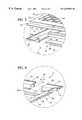
- FIG. 1is a perspective view of a screen assembly incorporating a seal constructed in accordance with the present invention
- FIG. 2is an exploded, fragmentary, perspective view of the screen assembly shown in FIG. 1 with a seal of the present invention
- FIG. 3is an enlarged detailed view of a portion of the screen assembly shown in FIG. 2;
- FIG. 4is an enlarged detailed view of a portion of the screen assembly shown in FIG. 2;
- FIG. 5is a top view of a frame which is an element of the screen assembly with a seal shown in FIG. 1;
- FIG. 6is a sectional view of the frame taken along section line 6 — 6 of FIG. 5;
- FIG. 7is a top view of a perforated plate which is an element of the screen assembly with a seal of the present invention.
- FIG. 8is a partial, exploded sectional view of the screen assembly with a seal of the present invention taken along section line 8 — 8 of FIG. 5;
- FIG. 9is a sectional view taken along section line 9 — 9 of FIG. 8;
- FIG. 10is a partial, exploded view of a screen assembly with a seal constructed in accordance with the present invention taken along section line 10 — 10 of FIG. 5;
- FIG. 11is a sectional view taken along section line 11 — 11 of FIG. 4;
- FIG. 12is a partial side view showing two disengaged screen assemblies, with a seal of the present invention.
- FIG. 13is a side view showing two engaged screen assemblies, with a seal of the present invention.
- FIGS. 1 and 2are perspective views of a screen assembly 10 which incorporates a seal mechanism of the present invention.
- a frame 12includes a pair of opposed sides 14 and 16 , a first opposed end 18 and a second opposed end 20 .
- the sides 14 and 16are opposed and parallel to each other.
- the first opposed end 18is parallel to second opposed end 20 .
- the sides 14 and 16are all composed of the same extruded aluminum material although other materials are possible.
- the first end 18has a seal shoulder 70 on top of planar surface 28 .
- the second end 20has an under surface 74 with an end stop 76 .
- the seal shoulder 70engages: (1) the vibrating screen machinery (not shown), or (2) an under surface of an adjoining screen assembly, as shown in FIGS. 12 and 13, to be discussed below.
- the seal mechanismcreates a fluid-tight seal to prevent passage of any liquid.
- Each side 14 and 16has a flat, planar surface 24 and 26 , respectively.
- First opposed end 18has a planar surface 28 .
- Second opposed end 20has a planar surface 30 .
- the side 14includes an upstanding lip 32 extending vertically from the planar surface 24 .
- the side 16includes an upstanding lip 34 extending vertically from the planar surface 26 .
- the first end 18includes an upstanding lip 36 extending vertically from the planar surface 28 .
- the second end 20includes an upstanding lip 38 extending vertically from the planar surface 30 .
- the lips 32 , 34 , 36 and 38together define a rim enclosure.
- the frame 12also includes a plurality of tubular cross supports 40 , 42 , 44 , 46 , 48 and 50 . It will be appreciated that a greater or lesser number of tubular supports might be employed.
- the tubular supportsextend between the sides 14 and 16 and are parallel to first opposed end 18 and second opposed end 20 .
- the tubular cross supports 40 , 42 , 44 , 46 , 48 and 50 in the present embodimentare narrower at the top than the bottom in cross-section although other configurations are possible within the scope of the invention.
- FIG. 7illustrates a top view of a perforated plate 52 apart from the screen assembly.
- the perforated plate 52is attached to and secured to the frame 12 in the assembled condition.
- the perforated plate 52includes a plurality of openings 54 which are punched or otherwise formed in the plate 52 .
- the support structure for the perforated plate 52is best shown in FIG. 2 .
- the perforated plate 52also includes a border area 55 which aligns with the planar surfaces of the frame 12 , providing an area for good adhesion between the frame and the plate 52 .
- FIGS. 8 and 9illustrate a partial, sectional views of the frame 12 , the perforated plate 52 , the seal shoulder 70 , and a plurality of screen cloth layers 53 .
- Three screen cloth layers 53are used in the present embodiment although a greater or lesser number could be utilized.
- Opposed side 14includes a downwardly extending leg 56 which extends downward perpendicularly from the planar surface 24 to ledge 64 .
- a ledge 64extends perpendicular to the downward leg 56 of side 14 .
- a ledge 66extends perpendicular to the downward leg 58 of side 16 .
- the ledges 64 and 66are aligned with and are opposed to each other.
- the tubular cross supports 40 , 42 , 44 , 46 , 48 and 50each extend between the frame sides 14 and 16 .
- the tubular cross supports 40 , 42 , 44 , 46 , 48 and 50rest on and are connected to both the downwardly extending legs 56 and 58 and the ledges 64 and 66 .
- the ledges 64 and 66(as well as the legs) facilitate welding of each of the cross supports 40 , 42 , 44 , 46 , 48 and 50 to the sides. Once assembled, the tubular cross supports 40 , 42 , 44 , 46 , 48 and 50 are aligned with the planar surfaces 24 , 26 , 28 and 30 .
- FIG. 10illustrates a partial sectional view of the end 20 including the end stop 76 .
- the frame 12is adhesively secured to the perforated plate 52 with adhesive.
- the plate 52 and the accompanying screen cloths 53are aligned on the frame by the lip 38 , which forms a rim enclosure with the lips 32 , 34 , and 36 .
- FIG. 11is a cross-sectional view taken along lines 11 — 11 of FIG. 10 .
- Tubular cross supports 48 and 50are positioned between side planar surface 24 and ledge 64 .
- FIGS. 12 and 13show the engagement of adjoining screen assemblies 10 A and 10 B for use in vibrating machinery that accommodates such adjoining screen assemblies.
- FIG. 12shows the two vibrating screen assemblies 10 A and 10 B prior to engagement.
- the seal shoulder 70 Bis inserted underneath the planar surface 30 A until it reaches the end stop 76 A.
- FIG. 13shows the completed installation with the seal shoulder 70 B engaging the seal bracket 74 A at an engagement line 84 .
- the lip 36 Bengages the end stop 76 A at stop segment 86 .
- the stop segment 86locates the seal shoulder properly to create a seal at the engagement line. It will be understood that it is possible to create a seal without the end stop.
- a rubber gasket 88 Ahelps to minimize gaps between the seal shoulder 70 B and undersurface 74 of the end caused by the vibration of the screen assemblies 10 A and 10 B in the vibrating machinery.
- the installed adjoining screen assemblies 10 A and 10 Bare not aligned but have an angle between them, typically about 10 degrees.
- the process for producing a seal and screen assembly 10 of the present inventionincludes a number of steps. Initially, the sides 14 and 16 and ends 18 and 20 of the frame 12 are extruded in lengths, such as from extruded aluminum. This extrusion process uses three different dies, as described below. These frame sections are then cut to desired lengths to form a pair of opposed sides 14 and 16 , a first end 18 and a second end 20 . The sides may be of the same frame design. The sides and the ends are cut at 45° angles (as best seen in FIG. 5) so that they will mate together to form an exterior frame. The rubber gasket 88 A is glued to the seal bracket 74 .
- the seal shoulder 70is rigidly attached to the planar surface 28 by adhesive.
- the seal shoulder 70may be extruded as an integral part of the opposed end 18 .
- the seal shoulder 70is convex and extends above the level of the planar surface.
- Other configurations, such as a seal shoulder with a peaked cross-section,are possible.
- the end stop 76is extruded as an integral part of the opposed end 20 .
- tubular supportis extruded, such as from extruded aluminum.
- the tubular cross supports 40 , 42 , 44 , 46 , 48 and 50are cut from these lengths to the desired dimensions.
- the opposed sides 14 and 16 , the first opposed end 18 and the second opposed end 20are clamped together and welded. Thereafter, the entire frame 12 , including the cross supports, is welded together.
- end of the tubular cross supports 40 , 42 , 44 , 46 , 48 and 50rest on the ledges 64 and 66 .
- the connecting weld pointsmay require some minor surface grinding for a smooth finish.
- the perforated plate 52In usage on vibrating screen machinery, the perforated plate 52 is prevented from moving side to side or end to end with respect to the frame 12 because of the rim enclosure.
- the joints between the tubular cross supports 40 , 42 , 44 , 46 , 48 and 50 and the opposed sides 14 and 16are strengthened because the tubular cross supports 40 , 42 , 44 , 46 , 48 and 50 rest on the ledges 64 and 66 . Accordingly, only an upward force would act to separate the cross supports 40 , 42 , 44 , 46 , 48 and 50 from the opposed sides 14 and 16 .
Landscapes
- Chemical & Material Sciences (AREA)
- Chemical Kinetics & Catalysis (AREA)
- Combined Means For Separation Of Solids (AREA)
- Overhead Projectors And Projection Screens (AREA)
Abstract
Description
Claims (10)
Priority Applications (4)
| Application Number | Priority Date | Filing Date | Title |
|---|---|---|---|
| US09/317,385US6269954B1 (en) | 1997-09-02 | 1999-05-24 | Seal for adjoining screen assemblies in vibrating machinery |
| US09/420,089US6439392B1 (en) | 1997-09-02 | 1999-10-18 | Vibrating screen assembly with tubular frame |
| US10/040,202US6672460B2 (en) | 1997-09-02 | 2001-10-22 | Vibrating screen assembly with integrated gasket and frame |
| US10/753,065US20040245154A1 (en) | 1997-09-02 | 2004-01-06 | Vibrating screen assembly with integrated gasket and frame |
Applications Claiming Priority (2)
| Application Number | Priority Date | Filing Date | Title |
|---|---|---|---|
| US08/922,205US5967336A (en) | 1997-09-02 | 1997-09-02 | Vibrating screen assembly with improved frame |
| US09/317,385US6269954B1 (en) | 1997-09-02 | 1999-05-24 | Seal for adjoining screen assemblies in vibrating machinery |
Related Parent Applications (1)
| Application Number | Title | Priority Date | Filing Date |
|---|---|---|---|
| US08/922,205Continuation-In-PartUS5967336A (en) | 1997-09-02 | 1997-09-02 | Vibrating screen assembly with improved frame |
Related Child Applications (2)
| Application Number | Title | Priority Date | Filing Date |
|---|---|---|---|
| US09/420,089Continuation-In-PartUS6439392B1 (en) | 1997-09-02 | 1999-10-18 | Vibrating screen assembly with tubular frame |
| US10/040,202Continuation-In-PartUS6672460B2 (en) | 1997-09-02 | 2001-10-22 | Vibrating screen assembly with integrated gasket and frame |
Publications (1)
| Publication Number | Publication Date |
|---|---|
| US6269954B1true US6269954B1 (en) | 2001-08-07 |
Family
ID=25446692
Family Applications (2)
| Application Number | Title | Priority Date | Filing Date |
|---|---|---|---|
| US08/922,205Expired - LifetimeUS5967336A (en) | 1997-09-02 | 1997-09-02 | Vibrating screen assembly with improved frame |
| US09/317,385Expired - LifetimeUS6269954B1 (en) | 1997-09-02 | 1999-05-24 | Seal for adjoining screen assemblies in vibrating machinery |
Family Applications Before (1)
| Application Number | Title | Priority Date | Filing Date |
|---|---|---|---|
| US08/922,205Expired - LifetimeUS5967336A (en) | 1997-09-02 | 1997-09-02 | Vibrating screen assembly with improved frame |
Country Status (5)
| Country | Link |
|---|---|
| US (2) | US5967336A (en) |
| DE (1) | DE19882630B4 (en) |
| GB (1) | GB2343638B (en) |
| NO (1) | NO322593B1 (en) |
| WO (1) | WO1999011394A1 (en) |
Cited By (42)
| Publication number | Priority date | Publication date | Assignee | Title |
|---|---|---|---|---|
| US6412644B1 (en) | 2000-11-17 | 2002-07-02 | Varco I/P, Inc. | Vibratory separator |
| US6450345B1 (en) | 1993-04-30 | 2002-09-17 | Varco I/P, Inc. | Glue pattern screens and methods of production |
| US20030038061A1 (en)* | 1993-04-30 | 2003-02-27 | Schulte David L. | Screen with unibody structure |
| US6543621B2 (en)* | 2001-08-16 | 2003-04-08 | Southwestern Wire Cloth, Inc. | Integrated gasket and screen frame |
| US6581781B1 (en) | 1993-04-30 | 2003-06-24 | Tuboscope I/P, Inc. | Vibrator separator screens |
| US6607080B2 (en) | 1993-04-30 | 2003-08-19 | Varco I/P, Inc. | Screen assembly for vibratory separators |
| US6629610B1 (en) | 1993-04-30 | 2003-10-07 | Tuboscope I/P, Inc. | Screen with ramps for vibratory separator system |
| US20030222032A1 (en)* | 2002-05-29 | 2003-12-04 | Rudiger Tueshaus | Filtering screen construction and methods |
| US6669985B2 (en) | 1998-10-30 | 2003-12-30 | Varco I/P, Inc. | Methods for making glued shale shaker screens |
| US20040065627A1 (en)* | 2002-07-08 | 2004-04-08 | Filtrox Ag | Precoat filter cartridge, precoat cartridge filter and use of a filter cartridge |
| US6722504B2 (en) | 1993-04-30 | 2004-04-20 | Varco I/P, Inc. | Vibratory separators and screens |
| WO2004035235A1 (en)* | 2002-10-17 | 2004-04-29 | Varco I/P, Inc. | A screen support |
| US6736270B2 (en) | 1998-10-30 | 2004-05-18 | Varco I/P, Inc. | Glued screens for shale shakers |
| US20040144694A1 (en)* | 2001-02-23 | 2004-07-29 | Thor Bjornstad | Method and a device for extending the lifetime of a screen-cloth |
| US6769550B2 (en) | 2002-01-16 | 2004-08-03 | Varco I/P, Inc. | Screen assemblies for shale shakers |
| US20040245153A1 (en)* | 2003-05-02 | 2004-12-09 | Seyffert Kenneth W. | Screens and seals for vibratory separators |
| US20040251174A1 (en)* | 2003-05-02 | 2004-12-16 | Seyffert Kenneth W. | Removable seal apparatus for vibratory separator |
| US20050000865A1 (en)* | 1998-10-30 | 2005-01-06 | Schulte David L. | Screen assemblies and vibratory separators |
| US20050035033A1 (en)* | 1999-03-25 | 2005-02-17 | Adams Thomas C. | Methods for sealing screen assemblies on vibratory separators |
| US20050056570A1 (en)* | 2003-08-29 | 2005-03-17 | Colgrove James R. | Vibratory screen assemblies |
| US20050067327A1 (en)* | 2002-01-16 | 2005-03-31 | Adams Thomas C. | Screen assemblies for shale shakers |
| US20050103689A1 (en)* | 2001-10-19 | 2005-05-19 | Schulte David L.Jr. | Sealing screen assemblies and vibratory separators |
| US20050118457A1 (en)* | 2003-11-07 | 2005-06-02 | Seiko Epson Corporation | Organic electro-luminescence apparatus and electronic equipment |
| US6932883B2 (en) | 1998-10-30 | 2005-08-23 | Varco I/P, Inc. | Screens for vibratory separators |
| US7000777B2 (en) | 1998-10-30 | 2006-02-21 | Varco I/P, Inc. | Vibratory separator screens |
| US20060163122A1 (en)* | 2005-01-21 | 2006-07-27 | Bakula John J | Vibratory material screen with seal |
| US20060219608A1 (en)* | 2003-02-04 | 2006-10-05 | Eric Scott | Connected screens for vibratory separators |
| US20070125688A1 (en)* | 2005-12-06 | 2007-06-07 | Rotex, Inc. | Screening machine, associated screen panel and seal |
| US20070227954A1 (en)* | 2006-03-30 | 2007-10-04 | M-I Llc | Composite screen |
| US20080078702A1 (en)* | 2006-09-29 | 2008-04-03 | M-I Llc | Sealing system for pre-tensioned composite screens |
| US20080078701A1 (en)* | 2006-09-29 | 2008-04-03 | M-I Llc | Peripheral sealing system for pre-tensioned screens |
| US20080223761A1 (en)* | 2007-03-14 | 2008-09-18 | Rotex, Inc. | Sealing Mechanism and Associated Sealing Method for Screening Machines |
| US20080245707A1 (en)* | 2007-04-04 | 2008-10-09 | M-I Llc | Pre-tensioned sifter screen |
| US7520391B2 (en) | 1999-12-04 | 2009-04-21 | Varco I/P, Inc. | Screen assembly for vibratory separator |
| US20090230029A1 (en)* | 2005-12-06 | 2009-09-17 | Rotex Global, Llc | Screening machine and associated screen panel |
| US20100006481A1 (en)* | 2008-07-08 | 2010-01-14 | Miller Wire Works | Mechanism for Securing Screen Modules |
| US20110036759A1 (en)* | 2005-12-06 | 2011-02-17 | Rotex, Inc. | Screening machine and associated screen panel |
| US20150258575A1 (en)* | 2012-07-27 | 2015-09-17 | M-I L.L.C. | Composite screen frame with semi-flexible mechanical strain relief |
| US20160288171A1 (en)* | 2015-04-02 | 2016-10-06 | Continental Wire Cloth, LLC | Vibratory shaker screen assembly |
| US10161410B2 (en) | 2015-02-24 | 2018-12-25 | Geiger Pump & Equipment | Seal bracket assembly and pump and motor system including same |
| US10711545B2 (en)* | 2015-05-03 | 2020-07-14 | Elgin Separation Solutions Industrials, Llc | Shale shaker with stair-stepped arrangements of screens and methods of using same, and methods of retrofitting shale shakers |
| USD1059521S1 (en)* | 2022-09-21 | 2025-01-28 | Karsten Manufacturing Corporation | Golf club head |
Families Citing this family (26)
| Publication number | Priority date | Publication date | Assignee | Title |
|---|---|---|---|---|
| US6186337B1 (en) | 1998-10-30 | 2001-02-13 | Tuboscope I/P, Inc. | Dual screen element having upper scalping screen adhered to crests of corrugated lower screen |
| US6443310B1 (en) | 1993-04-30 | 2002-09-03 | Varco I/P, Inc. | Seal screen structure |
| US6565698B1 (en) | 1993-04-30 | 2003-05-20 | Varco I/P, Inc. | Method for making vibratory separator screens |
| US6290068B1 (en) | 1993-04-30 | 2001-09-18 | Tuboscope I/P, Inc. | Shaker screens and methods of use |
| US6401934B1 (en) | 1993-04-30 | 2002-06-11 | Tuboscope I/P, Inc. | Ramped screen & vibratory separator system |
| US6325216B1 (en) | 1993-04-30 | 2001-12-04 | Tuboscope I/P, Inc. | Screen apparatus for vibratory separator |
| US6152307A (en) | 1993-04-30 | 2000-11-28 | Tuboscope I/P, Inc. | Vibratory separator screens |
| US6371302B1 (en) | 1993-04-30 | 2002-04-16 | Tuboscope I/P, Inc. | Vibratory separator screens |
| US6269953B1 (en) | 1993-04-30 | 2001-08-07 | Tuboscope I/P, Inc. | Vibratory separator screen assemblies |
| US6267247B1 (en) | 1993-04-30 | 2001-07-31 | Tuboscope I/P, Inc. | Vibratory separator screen |
| US6672460B2 (en) | 1997-09-02 | 2004-01-06 | Southwestern Wire Cloth, Inc. | Vibrating screen assembly with integrated gasket and frame |
| US6439392B1 (en)* | 1997-09-02 | 2002-08-27 | Southwestern Wire Cloth, Inc. | Vibrating screen assembly with tubular frame |
| US20020104611A1 (en)* | 1998-10-30 | 2002-08-08 | Adams Thomas C. | Self-flattening screens for vibratory separators |
| US20040112522A1 (en)* | 1998-10-30 | 2004-06-17 | Ward Kerry T. | Automated methods for making screen assemblies for vibratory separators |
| CA2370549C (en) | 1999-06-24 | 2009-01-13 | Tuboscope I/P Inc. | A screen, a panel for a screen, a shale shaker and a method of screening |
| US6305549B1 (en)* | 1999-07-06 | 2001-10-23 | Southwestern Wire Cloth, Inc. | Vibrating screen assembly of dissimilar materials |
| US6220449B1 (en) | 1999-10-01 | 2001-04-24 | Tuboscope I/P, Inc. | Flat top cloth support screen |
| US6530482B1 (en) | 2000-04-26 | 2003-03-11 | Michael D. Wiseman | Tandem shale shaker |
| US20050224398A1 (en)* | 2001-10-19 | 2005-10-13 | Largent David W | Vibratory separators and sealing screens |
| US20070125687A1 (en)* | 2005-12-01 | 2007-06-07 | Kutryk Edward A | Screen assembly for a vibratory separator |
| US8393474B2 (en) | 2006-09-29 | 2013-03-12 | United Wire Limited | Injection molded grid for saving screen frames |
| US20090071561A1 (en)* | 2007-09-12 | 2009-03-19 | Dennis Dalrymple | Method and system for improving gas flow in a duct or pipe |
| US20090145816A1 (en)* | 2007-12-11 | 2009-06-11 | Paul William Dufilho | Screen assemblies for shale shakers |
| US9694392B2 (en)* | 2015-09-24 | 2017-07-04 | Rotex Global, Llc | Screen panel frame with plate |
| EP3785811A1 (en)* | 2019-08-27 | 2021-03-03 | Metso Minerals, Inc. | Screening device |
| CN112387580B (en)* | 2020-10-26 | 2022-04-12 | 靖州异溪茯苓食品有限责任公司 | Cleaning and impurity removing device for hickory production and processing and use method thereof |
Citations (32)
| Publication number | Priority date | Publication date | Assignee | Title |
|---|---|---|---|---|
| US1009069A (en) | 1911-04-26 | 1911-11-21 | Charles Hunnicutt | Seed-corn grader. |
| US1147279A (en) | 1914-05-25 | 1915-07-20 | Ernest J Sweetland | Filter medium or other article of manufacture. |
| US2271900A (en) | 1939-01-31 | 1942-02-03 | Cambridge Wire Cloth | Screen |
| US2335084A (en) | 1940-04-29 | 1943-11-23 | Mission Rubber Company | Sifter |
| US2576794A (en) | 1948-07-19 | 1951-11-27 | William R Jost | Demountable tray sieve |
| US2870910A (en) | 1954-03-15 | 1959-01-27 | Brueckenbau Flender Gmbh | Screen for use in oscillating screening devices |
| US2902165A (en) | 1957-03-04 | 1959-09-01 | Multi Metal Wire Cloth Co Inc | Filter leaf and method of assembling it |
| US2959285A (en) | 1958-05-01 | 1960-11-08 | Gilson Screen Company | Screening device and clamp means therefor |
| US3012674A (en) | 1958-06-16 | 1961-12-12 | Hoppe Gerhard | Oscillating screen structure |
| US3508649A (en) | 1967-08-04 | 1970-04-28 | Separator Eng Ltd | Anti-blinding device for vibratory separator |
| US3970549A (en) | 1973-06-18 | 1976-07-20 | Linatex Corporation Of America | Screen assembly and dewatering technique |
| EP0032436A1 (en) | 1980-01-12 | 1981-07-22 | N. Greening Limited | Screening apparatus |
| GB2092917A (en) | 1981-02-13 | 1982-08-25 | Bba Group Ltd | Screens |
| US4360426A (en)* | 1981-03-02 | 1982-11-23 | Fmc Corporation | Joint between traveling water screen trays |
| US4380494A (en) | 1980-04-14 | 1983-04-19 | Litton Systems, Inc. | Vibrating screen with self-supporting screen cloth |
| EP0169698A2 (en) | 1984-07-21 | 1986-01-29 | Thule United Limited | Improvements in filtering screens |
| US4668394A (en) | 1983-01-10 | 1987-05-26 | Mcneilab, Inc. | Filtration media and supporting frame |
| US4728422A (en) | 1984-07-21 | 1988-03-01 | Thule United Limited | Sifting frame assembly with differentially tensioned screens |
| US4840728A (en) | 1988-03-14 | 1989-06-20 | Conn-Weld Industries, Inc. | Vibrating screening apparatus |
| US5137622A (en) | 1988-09-27 | 1992-08-11 | United Wire Limited | Filter screen assembly |
| US5199574A (en) | 1991-10-31 | 1993-04-06 | J & H Equipment, Inc. | Vibrating screen separator |
| US5248043A (en) | 1992-02-28 | 1993-09-28 | Dorn Lloyd A | Modular retro-fit screen system for a screening deck |
| US5256291A (en) | 1992-04-16 | 1993-10-26 | Cagle William S | Screen for filtering undesirable particles from a liquid |
| GB2276572A (en) | 1993-03-31 | 1994-10-05 | Filter Screen Supply Limited | Screen frame assembly with frame-bonded screen cloth and removable ball tray |
| US5361476A (en) | 1992-08-13 | 1994-11-08 | Glass Equipment Development, Inc. | Method of making a spacer frame assembly |
| US5385669A (en) | 1993-04-30 | 1995-01-31 | Environmental Procedures, Inc. | Mining screen device and grid structure therefor |
| US5392925A (en)* | 1993-08-12 | 1995-02-28 | Environmental Procedures, Inc. | Shale shaker and screen |
| US5417859A (en) | 1993-01-13 | 1995-05-23 | Derrick Manufacturing Corporation | Undulating screen for vibratory screening machine and method of fabrication thereof |
| US5636749A (en) | 1995-05-18 | 1997-06-10 | Derrick Manufacturing Corporation | Undulating screen for vibratory screening machine |
| US5950841A (en)* | 1998-07-22 | 1999-09-14 | Emerson Electric Co. | Screen assembly for a vibratory separator |
| US6053329A (en)* | 1998-04-14 | 2000-04-25 | Rotex, Inc | Vibratory frame mounting structure for screening machines |
| US6070736A (en)* | 1998-11-09 | 2000-06-06 | Rotex, Inc. | Sealing mechanism and method for screening machines |
Family Cites Families (5)
| Publication number | Priority date | Publication date | Assignee | Title |
|---|---|---|---|---|
| DE872723C (en)* | 1951-06-07 | 1953-04-02 | Siteg Siebtech Gmbh | Method for fixing screen linings on plastic frames |
| DE2240051C2 (en)* | 1972-08-16 | 1982-06-09 | Hein, Lehmann AG, 4000 Düsseldorf | Sieve bottom |
| DE3425485A1 (en)* | 1984-07-11 | 1986-01-16 | Hein, Lehmann AG, 4000 Düsseldorf | SCREENING |
| CH685604A5 (en)* | 1992-02-29 | 1995-08-31 | Buehler Ag | Plansifter. |
| US5417858A (en)* | 1993-01-13 | 1995-05-23 | Derrick Manufacturing Corporation | Screen assembly for vibrating screening machine |
- 1997
- 1997-09-02USUS08/922,205patent/US5967336A/ennot_activeExpired - Lifetime
- 1998
- 1998-08-13GBGB0002622Apatent/GB2343638B/ennot_activeExpired - Lifetime
- 1998-08-13DEDE19882630Tpatent/DE19882630B4/ennot_activeExpired - Lifetime
- 1998-08-13WOPCT/US1998/016811patent/WO1999011394A1/enactiveApplication Filing
- 1999
- 1999-05-24USUS09/317,385patent/US6269954B1/ennot_activeExpired - Lifetime
- 2000
- 2000-01-18NONO20000237Apatent/NO322593B1/ennot_activeIP Right Cessation
Patent Citations (32)
| Publication number | Priority date | Publication date | Assignee | Title |
|---|---|---|---|---|
| US1009069A (en) | 1911-04-26 | 1911-11-21 | Charles Hunnicutt | Seed-corn grader. |
| US1147279A (en) | 1914-05-25 | 1915-07-20 | Ernest J Sweetland | Filter medium or other article of manufacture. |
| US2271900A (en) | 1939-01-31 | 1942-02-03 | Cambridge Wire Cloth | Screen |
| US2335084A (en) | 1940-04-29 | 1943-11-23 | Mission Rubber Company | Sifter |
| US2576794A (en) | 1948-07-19 | 1951-11-27 | William R Jost | Demountable tray sieve |
| US2870910A (en) | 1954-03-15 | 1959-01-27 | Brueckenbau Flender Gmbh | Screen for use in oscillating screening devices |
| US2902165A (en) | 1957-03-04 | 1959-09-01 | Multi Metal Wire Cloth Co Inc | Filter leaf and method of assembling it |
| US2959285A (en) | 1958-05-01 | 1960-11-08 | Gilson Screen Company | Screening device and clamp means therefor |
| US3012674A (en) | 1958-06-16 | 1961-12-12 | Hoppe Gerhard | Oscillating screen structure |
| US3508649A (en) | 1967-08-04 | 1970-04-28 | Separator Eng Ltd | Anti-blinding device for vibratory separator |
| US3970549A (en) | 1973-06-18 | 1976-07-20 | Linatex Corporation Of America | Screen assembly and dewatering technique |
| EP0032436A1 (en) | 1980-01-12 | 1981-07-22 | N. Greening Limited | Screening apparatus |
| US4380494A (en) | 1980-04-14 | 1983-04-19 | Litton Systems, Inc. | Vibrating screen with self-supporting screen cloth |
| GB2092917A (en) | 1981-02-13 | 1982-08-25 | Bba Group Ltd | Screens |
| US4360426A (en)* | 1981-03-02 | 1982-11-23 | Fmc Corporation | Joint between traveling water screen trays |
| US4668394A (en) | 1983-01-10 | 1987-05-26 | Mcneilab, Inc. | Filtration media and supporting frame |
| EP0169698A2 (en) | 1984-07-21 | 1986-01-29 | Thule United Limited | Improvements in filtering screens |
| US4728422A (en) | 1984-07-21 | 1988-03-01 | Thule United Limited | Sifting frame assembly with differentially tensioned screens |
| US4840728A (en) | 1988-03-14 | 1989-06-20 | Conn-Weld Industries, Inc. | Vibrating screening apparatus |
| US5137622A (en) | 1988-09-27 | 1992-08-11 | United Wire Limited | Filter screen assembly |
| US5199574A (en) | 1991-10-31 | 1993-04-06 | J & H Equipment, Inc. | Vibrating screen separator |
| US5248043A (en) | 1992-02-28 | 1993-09-28 | Dorn Lloyd A | Modular retro-fit screen system for a screening deck |
| US5256291A (en) | 1992-04-16 | 1993-10-26 | Cagle William S | Screen for filtering undesirable particles from a liquid |
| US5361476A (en) | 1992-08-13 | 1994-11-08 | Glass Equipment Development, Inc. | Method of making a spacer frame assembly |
| US5417859A (en) | 1993-01-13 | 1995-05-23 | Derrick Manufacturing Corporation | Undulating screen for vibratory screening machine and method of fabrication thereof |
| GB2276572A (en) | 1993-03-31 | 1994-10-05 | Filter Screen Supply Limited | Screen frame assembly with frame-bonded screen cloth and removable ball tray |
| US5385669A (en) | 1993-04-30 | 1995-01-31 | Environmental Procedures, Inc. | Mining screen device and grid structure therefor |
| US5392925A (en)* | 1993-08-12 | 1995-02-28 | Environmental Procedures, Inc. | Shale shaker and screen |
| US5636749A (en) | 1995-05-18 | 1997-06-10 | Derrick Manufacturing Corporation | Undulating screen for vibratory screening machine |
| US6053329A (en)* | 1998-04-14 | 2000-04-25 | Rotex, Inc | Vibratory frame mounting structure for screening machines |
| US5950841A (en)* | 1998-07-22 | 1999-09-14 | Emerson Electric Co. | Screen assembly for a vibratory separator |
| US6070736A (en)* | 1998-11-09 | 2000-06-06 | Rotex, Inc. | Sealing mechanism and method for screening machines |
Cited By (71)
| Publication number | Priority date | Publication date | Assignee | Title |
|---|---|---|---|---|
| US6607080B2 (en) | 1993-04-30 | 2003-08-19 | Varco I/P, Inc. | Screen assembly for vibratory separators |
| US6450345B1 (en) | 1993-04-30 | 2002-09-17 | Varco I/P, Inc. | Glue pattern screens and methods of production |
| US20030038061A1 (en)* | 1993-04-30 | 2003-02-27 | Schulte David L. | Screen with unibody structure |
| US6530483B2 (en) | 1993-04-30 | 2003-03-11 | Varco I/P, Inc. | Unibody structure for screen assembly |
| US6581781B1 (en) | 1993-04-30 | 2003-06-24 | Tuboscope I/P, Inc. | Vibrator separator screens |
| US6629610B1 (en) | 1993-04-30 | 2003-10-07 | Tuboscope I/P, Inc. | Screen with ramps for vibratory separator system |
| US6892888B2 (en)* | 1993-04-30 | 2005-05-17 | Varco I/P, Inc. | Screen with unibody structure |
| US6722504B2 (en) | 1993-04-30 | 2004-04-20 | Varco I/P, Inc. | Vibratory separators and screens |
| US7000777B2 (en) | 1998-10-30 | 2006-02-21 | Varco I/P, Inc. | Vibratory separator screens |
| US20050000865A1 (en)* | 1998-10-30 | 2005-01-06 | Schulte David L. | Screen assemblies and vibratory separators |
| US6669985B2 (en) | 1998-10-30 | 2003-12-30 | Varco I/P, Inc. | Methods for making glued shale shaker screens |
| US6736270B2 (en) | 1998-10-30 | 2004-05-18 | Varco I/P, Inc. | Glued screens for shale shakers |
| US6932883B2 (en) | 1998-10-30 | 2005-08-23 | Varco I/P, Inc. | Screens for vibratory separators |
| US20050035033A1 (en)* | 1999-03-25 | 2005-02-17 | Adams Thomas C. | Methods for sealing screen assemblies on vibratory separators |
| US7520391B2 (en) | 1999-12-04 | 2009-04-21 | Varco I/P, Inc. | Screen assembly for vibratory separator |
| US7000776B2 (en)* | 2000-08-05 | 2006-02-21 | Varco I/P, Inc. | Screen assembly for vibratory separators |
| US6715611B2 (en) | 2000-11-17 | 2004-04-06 | Tuboscope I/P, Inc. | Vibratory separator |
| US6412644B1 (en) | 2000-11-17 | 2002-07-02 | Varco I/P, Inc. | Vibratory separator |
| US20040144694A1 (en)* | 2001-02-23 | 2004-07-29 | Thor Bjornstad | Method and a device for extending the lifetime of a screen-cloth |
| US6543621B2 (en)* | 2001-08-16 | 2003-04-08 | Southwestern Wire Cloth, Inc. | Integrated gasket and screen frame |
| US20050103689A1 (en)* | 2001-10-19 | 2005-05-19 | Schulte David L.Jr. | Sealing screen assemblies and vibratory separators |
| US6769550B2 (en) | 2002-01-16 | 2004-08-03 | Varco I/P, Inc. | Screen assemblies for shale shakers |
| US20050067327A1 (en)* | 2002-01-16 | 2005-03-31 | Adams Thomas C. | Screen assemblies for shale shakers |
| US20060000786A1 (en)* | 2002-05-29 | 2006-01-05 | Ruediger Tueshaus | Filtering screen construction and methods |
| US20030222032A1 (en)* | 2002-05-29 | 2003-12-04 | Rudiger Tueshaus | Filtering screen construction and methods |
| US20040065627A1 (en)* | 2002-07-08 | 2004-04-08 | Filtrox Ag | Precoat filter cartridge, precoat cartridge filter and use of a filter cartridge |
| WO2004035235A1 (en)* | 2002-10-17 | 2004-04-29 | Varco I/P, Inc. | A screen support |
| US20060219608A1 (en)* | 2003-02-04 | 2006-10-05 | Eric Scott | Connected screens for vibratory separators |
| US20040251174A1 (en)* | 2003-05-02 | 2004-12-16 | Seyffert Kenneth W. | Removable seal apparatus for vibratory separator |
| US20040245153A1 (en)* | 2003-05-02 | 2004-12-09 | Seyffert Kenneth W. | Screens and seals for vibratory separators |
| US7040488B2 (en)* | 2003-05-02 | 2006-05-09 | Varco I/P, Inc. | Screens and seals for vibratory separators |
| US6955262B2 (en) | 2003-05-02 | 2005-10-18 | Varco, I/P Inc. | Removable seal apparatus for vibratory separator |
| US7011218B2 (en)* | 2003-08-29 | 2006-03-14 | Derrick Corporation | Vibratory screen assemblies |
| US20050056570A1 (en)* | 2003-08-29 | 2005-03-17 | Colgrove James R. | Vibratory screen assemblies |
| AU2004270140B2 (en)* | 2003-08-29 | 2010-05-27 | Derrick Corporation | Vibratory screen assemblies |
| RU2395350C2 (en)* | 2003-08-29 | 2010-07-27 | Деррик Корпорейшн | Units with vibration screens |
| US20050056571A1 (en)* | 2003-08-29 | 2005-03-17 | Derrick Manufacturing Corporation | Vibratory screen assemblies |
| US7175028B2 (en)* | 2003-08-29 | 2007-02-13 | Derrick Corporation | Vibratory screen assemblies |
| WO2005023439A3 (en)* | 2003-08-29 | 2005-08-18 | Derrick Corp | Vibratory screen assemblies |
| US20050118457A1 (en)* | 2003-11-07 | 2005-06-02 | Seiko Epson Corporation | Organic electro-luminescence apparatus and electronic equipment |
| US7244517B2 (en) | 2003-11-07 | 2007-07-17 | Seiko Epson Corporation | Organic electro-luminescence apparatus and electronic equipment |
| US8312996B2 (en)* | 2005-01-21 | 2012-11-20 | Derrick Corporation | Vibratory material screen with seal |
| US20060163122A1 (en)* | 2005-01-21 | 2006-07-27 | Bakula John J | Vibratory material screen with seal |
| US20070125688A1 (en)* | 2005-12-06 | 2007-06-07 | Rotex, Inc. | Screening machine, associated screen panel and seal |
| US8261915B2 (en) | 2005-12-06 | 2012-09-11 | Rotex Global, Llc | Screening machine and associated screen panel |
| US8522981B2 (en) | 2005-12-06 | 2013-09-03 | Rotex Global, Llc | Screening machine and associated screen panel |
| WO2007067300A3 (en)* | 2005-12-06 | 2009-04-30 | Rotex | Screening machine, associated screen panel and seal |
| US20090230029A1 (en)* | 2005-12-06 | 2009-09-17 | Rotex Global, Llc | Screening machine and associated screen panel |
| US20110036759A1 (en)* | 2005-12-06 | 2011-02-17 | Rotex, Inc. | Screening machine and associated screen panel |
| US20100018910A1 (en)* | 2005-12-06 | 2010-01-28 | Rotex Global, Llc | Screening machine screen panel |
| US20070227954A1 (en)* | 2006-03-30 | 2007-10-04 | M-I Llc | Composite screen |
| US7753213B2 (en)* | 2006-03-30 | 2010-07-13 | M-I Llc | Composite screen |
| US20080078701A1 (en)* | 2006-09-29 | 2008-04-03 | M-I Llc | Peripheral sealing system for pre-tensioned screens |
| USRE45746E1 (en)* | 2006-09-29 | 2015-10-13 | M-I L.L.C. | Peripheral sealing system for pre-tensioned screens |
| US9149839B2 (en) | 2006-09-29 | 2015-10-06 | M-I L.L.C. | Sealing system for pre-tensioned composite screens |
| US7891497B2 (en)* | 2006-09-29 | 2011-02-22 | M-I L.L.C. | Peripheral sealing system for pre-tensioned screens |
| US20110139688A1 (en)* | 2006-09-29 | 2011-06-16 | M-I L.L.C. | Peripheral sealing system for pre-tensioned screens |
| US20080078702A1 (en)* | 2006-09-29 | 2008-04-03 | M-I Llc | Sealing system for pre-tensioned composite screens |
| US8496116B2 (en)* | 2006-09-29 | 2013-07-30 | M-I L.L.C. | Peripheral sealing system for pre-tensioned screens |
| US20080223761A1 (en)* | 2007-03-14 | 2008-09-18 | Rotex, Inc. | Sealing Mechanism and Associated Sealing Method for Screening Machines |
| US20080245707A1 (en)* | 2007-04-04 | 2008-10-09 | M-I Llc | Pre-tensioned sifter screen |
| US8113358B2 (en)* | 2007-04-04 | 2012-02-14 | M-I Llc | Pre-tensioned sifter screen |
| DE112009001455B4 (en)* | 2008-06-12 | 2014-07-17 | Rotex Global, Llc | Screening machine and associated screen plate |
| US20100006481A1 (en)* | 2008-07-08 | 2010-01-14 | Miller Wire Works | Mechanism for Securing Screen Modules |
| US7857142B2 (en) | 2008-07-08 | 2010-12-28 | Waites Jr Robert F | Mechanism for securing screen modules |
| US20150258575A1 (en)* | 2012-07-27 | 2015-09-17 | M-I L.L.C. | Composite screen frame with semi-flexible mechanical strain relief |
| US9393598B2 (en)* | 2012-07-27 | 2016-07-19 | M-I L.L.C. | Composite screen frame with semi-flexible mechanical strain relief |
| US10161410B2 (en) | 2015-02-24 | 2018-12-25 | Geiger Pump & Equipment | Seal bracket assembly and pump and motor system including same |
| US20160288171A1 (en)* | 2015-04-02 | 2016-10-06 | Continental Wire Cloth, LLC | Vibratory shaker screen assembly |
| US10711545B2 (en)* | 2015-05-03 | 2020-07-14 | Elgin Separation Solutions Industrials, Llc | Shale shaker with stair-stepped arrangements of screens and methods of using same, and methods of retrofitting shale shakers |
| USD1059521S1 (en)* | 2022-09-21 | 2025-01-28 | Karsten Manufacturing Corporation | Golf club head |
Also Published As
| Publication number | Publication date |
|---|---|
| GB2343638B (en) | 2002-06-12 |
| NO20000237L (en) | 2000-02-28 |
| DE19882630B4 (en) | 2005-03-10 |
| NO322593B1 (en) | 2006-10-30 |
| NO20000237D0 (en) | 2000-01-18 |
| DE19882630T1 (en) | 2000-07-27 |
| GB0002622D0 (en) | 2000-03-29 |
| US5967336A (en) | 1999-10-19 |
| GB2343638A (en) | 2000-05-17 |
| WO1999011394A1 (en) | 1999-03-11 |
Similar Documents
| Publication | Publication Date | Title |
|---|---|---|
| US6269954B1 (en) | Seal for adjoining screen assemblies in vibrating machinery | |
| US6439392B1 (en) | Vibrating screen assembly with tubular frame | |
| US6672460B2 (en) | Vibrating screen assembly with integrated gasket and frame | |
| US6401934B1 (en) | Ramped screen & vibratory separator system | |
| US6629610B1 (en) | Screen with ramps for vibratory separator system | |
| EP1305100B1 (en) | A screen arrangement and a support structure for a vibratory separator | |
| CA2472692C (en) | Apparatus for separating material | |
| US6371302B1 (en) | Vibratory separator screens | |
| US6662952B2 (en) | Shale shakers and screens for them | |
| US20020000399A1 (en) | Screen assemly for vibratory separators | |
| US6325216B1 (en) | Screen apparatus for vibratory separator | |
| US6454099B1 (en) | Vibrator separator screens | |
| US20050103689A1 (en) | Sealing screen assemblies and vibratory separators | |
| US6601709B2 (en) | Screen support and screens for shale shakers | |
| US6241098B1 (en) | Drilling fluid treatment operations and apparatuses | |
| US6302276B1 (en) | Screen support strip for use in vibratory screening apparatus | |
| US6053331A (en) | Non-tensioned shaker filter | |
| US20050224398A1 (en) | Vibratory separators and sealing screens | |
| US20050000865A1 (en) | Screen assemblies and vibratory separators | |
| US20050067327A1 (en) | Screen assemblies for shale shakers | |
| US11406921B2 (en) | Gasket for screen frame | |
| CN101010149A (en) | Screen assembly and shale shaker | |
| AU1852299A (en) | Vibrating screen assembly with improved frame | |
| CA2641636A1 (en) | Apparatus for separating material | |
| MX2007001838A (en) | Screen assembly and shale shaker. |
Legal Events
| Date | Code | Title | Description |
|---|---|---|---|
| AS | Assignment | Owner name:SOUTHWESTERN WIRE CLOTH, INC., OKLAHOMA Free format text:MORTGAGE;ASSIGNOR:BALTZER, TERRY L.;REEL/FRAME:009989/0579 Effective date:19990524 | |
| AS | Assignment | Owner name:SOUTHWESTERN WIRE CLOTH, INC., OKLAHOMA Free format text:CHANGE OF NAME;ASSIGNOR:MADISON DENVER, INC.;REEL/FRAME:011541/0006 Effective date:20000911 Owner name:MADISON DENVER, INC., OKLAHOMA Free format text:BILL OF SALE AND ASSIGNMENT;ASSIGNOR:SOUTHWESTERN WIRE CLOTH, INC.;REEL/FRAME:011541/0012 Effective date:20000824 | |
| STCF | Information on status: patent grant | Free format text:PATENTED CASE | |
| CC | Certificate of correction | ||
| FEPP | Fee payment procedure | Free format text:PAT HOLDER NO LONGER CLAIMS SMALL ENTITY STATUS, ENTITY STATUS SET TO UNDISCOUNTED (ORIGINAL EVENT CODE: STOL); ENTITY STATUS OF PATENT OWNER: LARGE ENTITY | |
| REFU | Refund | Free format text:REFUND - SURCHARGE, PETITION TO ACCEPT PYMT AFTER EXP, UNINTENTIONAL (ORIGINAL EVENT CODE: R2551); ENTITY STATUS OF PATENT OWNER: LARGE ENTITY | |
| FPAY | Fee payment | Year of fee payment:4 | |
| AS | Assignment | Owner name:M-I L.L.C., TEXAS Free format text:ASSIGNMENT OF ASSIGNORS INTEREST;ASSIGNOR:SOUTHWESTERN WIRE CLOTH INC.;REEL/FRAME:016016/0354 Effective date:20040530 | |
| FPAY | Fee payment | Year of fee payment:8 | |
| FPAY | Fee payment | Year of fee payment:12 |