US6269612B1 - Positive count rotary slat packaging apparatus and related methods - Google Patents
Positive count rotary slat packaging apparatus and related methodsDownload PDFInfo
- Publication number
- US6269612B1 US6269612B1US09/640,970US64097000AUS6269612B1US 6269612 B1US6269612 B1US 6269612B1US 64097000 AUS64097000 AUS 64097000AUS 6269612 B1US6269612 B1US 6269612B1
- Authority
- US
- United States
- Prior art keywords
- pills
- rotary
- containers
- slats
- pill
- Prior art date
- Legal status (The legal status is an assumption and is not a legal conclusion. Google has not performed a legal analysis and makes no representation as to the accuracy of the status listed.)
- Expired - Lifetime
Links
- 238000000034methodMethods0.000titleclaimsabstractdescription14
- 238000004806packaging method and processMethods0.000titleabstractdescription12
- 239000006187pillSubstances0.000claimsabstractdescription155
- 238000000151depositionMethods0.000claims8
- 125000006850spacer groupChemical group0.000description20
- 230000002093peripheral effectEffects0.000description5
- 230000008901benefitEffects0.000description4
- 239000002775capsuleSubstances0.000description3
- 238000012986modificationMethods0.000description3
- 230000004048modificationEffects0.000description3
- 238000005452bendingMethods0.000description2
- 230000036512infertilityEffects0.000description2
- 239000000463materialSubstances0.000description2
- 230000008439repair processEffects0.000description2
- 239000003826tabletSubstances0.000description2
- 229920001875EbonitePolymers0.000description1
- 229920006362Teflon®Polymers0.000description1
- 230000009471actionEffects0.000description1
- 238000013459approachMethods0.000description1
- 230000033228biological regulationEffects0.000description1
- 230000005540biological transmissionEffects0.000description1
- 239000007894capletSubstances0.000description1
- 230000003749cleanlinessEffects0.000description1
- 238000004891communicationMethods0.000description1
- 230000006835compressionEffects0.000description1
- 238000007906compressionMethods0.000description1
- 230000003247decreasing effectEffects0.000description1
- 239000003814drugSubstances0.000description1
- 229940079593drugDrugs0.000description1
- 239000000428dustSubstances0.000description1
- 230000007613environmental effectEffects0.000description1
- 230000010006flightEffects0.000description1
- 239000012530fluidSubstances0.000description1
- 239000007897gelcapSubstances0.000description1
- 238000003780insertionMethods0.000description1
- 230000037431insertionEffects0.000description1
- 238000002372labellingMethods0.000description1
- 230000033001locomotionEffects0.000description1
- 238000012423maintenanceMethods0.000description1
- 230000007257malfunctionEffects0.000description1
- 238000004519manufacturing processMethods0.000description1
- 239000013618particulate matterSubstances0.000description1
- 238000003825pressingMethods0.000description1
- 230000008569processEffects0.000description1
- 230000000452restraining effectEffects0.000description1
- 238000005096rolling processMethods0.000description1
Images


Classifications
- B—PERFORMING OPERATIONS; TRANSPORTING
- B65—CONVEYING; PACKING; STORING; HANDLING THIN OR FILAMENTARY MATERIAL
- B65B—MACHINES, APPARATUS OR DEVICES FOR, OR METHODS OF, PACKAGING ARTICLES OR MATERIALS; UNPACKING
- B65B5/00—Packaging individual articles in containers or receptacles, e.g. bags, sacks, boxes, cartons, cans, jars
- B65B5/10—Filling containers or receptacles progressively or in stages by introducing successive articles, or layers of articles
- B65B5/101—Filling containers or receptacles progressively or in stages by introducing successive articles, or layers of articles by gravity
- B65B5/103—Filling containers or receptacles progressively or in stages by introducing successive articles, or layers of articles by gravity for packaging pills or tablets
- B—PERFORMING OPERATIONS; TRANSPORTING
- B65—CONVEYING; PACKING; STORING; HANDLING THIN OR FILAMENTARY MATERIAL
- B65B—MACHINES, APPARATUS OR DEVICES FOR, OR METHODS OF, PACKAGING ARTICLES OR MATERIALS; UNPACKING
- B65B35/00—Supplying, feeding, arranging or orientating articles to be packaged
- B65B35/06—Separating single articles from loose masses of articles
- B65B35/08—Separating single articles from loose masses of articles using pocketed conveyors
- B—PERFORMING OPERATIONS; TRANSPORTING
- B65—CONVEYING; PACKING; STORING; HANDLING THIN OR FILAMENTARY MATERIAL
- B65B—MACHINES, APPARATUS OR DEVICES FOR, OR METHODS OF, PACKAGING ARTICLES OR MATERIALS; UNPACKING
- B65B57/00—Automatic control, checking, warning, or safety devices
- B65B57/10—Automatic control, checking, warning, or safety devices responsive to absence, presence, abnormal feed, or misplacement of articles or materials to be packaged
- B65B57/14—Automatic control, checking, warning, or safety devices responsive to absence, presence, abnormal feed, or misplacement of articles or materials to be packaged and operating to control, or stop, the feed of articles or material to be packaged
- B—PERFORMING OPERATIONS; TRANSPORTING
- B65—CONVEYING; PACKING; STORING; HANDLING THIN OR FILAMENTARY MATERIAL
- B65B—MACHINES, APPARATUS OR DEVICES FOR, OR METHODS OF, PACKAGING ARTICLES OR MATERIALS; UNPACKING
- B65B57/00—Automatic control, checking, warning, or safety devices
- B65B57/20—Applications of counting devices for controlling the feed of articles
- Y—GENERAL TAGGING OF NEW TECHNOLOGICAL DEVELOPMENTS; GENERAL TAGGING OF CROSS-SECTIONAL TECHNOLOGIES SPANNING OVER SEVERAL SECTIONS OF THE IPC; TECHNICAL SUBJECTS COVERED BY FORMER USPC CROSS-REFERENCE ART COLLECTIONS [XRACs] AND DIGESTS
- Y10—TECHNICAL SUBJECTS COVERED BY FORMER USPC
- Y10S—TECHNICAL SUBJECTS COVERED BY FORMER USPC CROSS-REFERENCE ART COLLECTIONS [XRACs] AND DIGESTS
- Y10S53/00—Package making
- Y10S53/90—Capsules
Definitions
- the present inventionrelates to packaging machines, and more particularly relates to automated packaging machines for filling container bottles with pills.
- pill filling machineshave been proposed which provide automated bottle counts by filling a hopper with pills and causing a plurality of the pills to be caught by a pill capturing device, such as an array of rotary slats.
- the rotary slatsdrop the captured pills into a plurality of bottles disposed in alignment with the dropping pills.
- the bottlesare distributed along an endless conveyor belt which is timed to advance and stop the bottles according to the filling operation.
- Conventional pill capturing devicesmore particularly include a series of rotary slats each configured to receive, hold and move a plurality of capsules or pills along a closed path.
- the rotary slatsare typically discs fixed on a rotatable shaft and having a plurality of openings in the peripheral surface thereof for capturing individual pills.
- the closed pathis arcuate and generally disposed between a pill hopper and discharge area above the conveyor belt.
- the pill capturing devicethen generally discharges the pills by rotating the slats which move corresponding to the closed path such that they fall out of the respective openings at the filling station.
- the pillsare often funneled through a chute which empties into a corresponding bottle.
- the count, or number of pills in the bottleis determined by positioning the bottles in the pill dropping zone for a predetermined time.
- the duration of the filling operation for each bottlecorresponds to the number of openings in each slat which the machine is capable of delivering to the bottles per unit of time.
- the duration of the filling operation, speed of the rotary slats and configuration of the pill capturing deviceare used to calculate the count.
- U.S. Pat. No. 3,139,713 to Merrillproposes a machine with a discharge chute which is divided into a number of discharge compartments corresponding to the number of bottles being filled at the filling operation. As described, each bottle is to be filled with a count of one hundred pills. Each discharge chute receives five pills from one row or flight of the pill capturing device when the capturing device reaches a discharge position. In order to complete the filling operation, each bottle in the row receives twenty of the 5-article carrying flights.
- U.S. Pat. No. 4,674,259 to Hillsproposes a series of elongated slats with cavities for carrying tablets to a set of chutes.
- the chutesoperate with reciprocating movement to deliver the pills between first and second rows of bottles positioned at the filling station.
- the pill capturing devicefails to capture a pill in each and every. cavity or receptacle, or if a pill should mistakenly be diverted, at least one of the bottles can be improperly filled.
- the conventional solution to this problemis to situate an operator adjacent to the slats to ensure that each receptacle is filled with a pill. If a pill is missing, the operator manually places a pill in the receptacle. Such an approach involves labor costs and can be unsatisfactory for sterility purposes.
- the packaging apparatus of the present inventionhaving a plurality of rotary slats, each of which is independently driven.
- a separate counting deviceis associated with each rotary slat for counting each pill as it falls from the slat into the container. As such, a positive count is provided for each container and improperly filled slats will not affect the total count for that container. If a particular container has a low count, the respective slat can be further rotated to fill the container. Because the slats are independently driven, the other slats can remain stationary to prevent overfilling.
- the packaging apparatuscomprises a reservoir configured to hold a plurality of randomly oriented pills and define at least one opening adjacent a lower portion thereof.
- the plurality of rotary slatseach have a peripheral edge portion rotatable into the opening in the reservoir.
- the peripheral edge portions of the rotary slatseach define a plurality of pill receptacles configured to capture an individual pill at a first position in the reservoir and release the pill at a second position outside of the reservoir.
- a conveyoris configured to move a plurality of open containers along a predetermined path of travel and position a container adjacent a respective rotary slat to define a delivery path extending between the second position of the rotary slat and the container.
- the pillsare released from the slat and fall along the delivery path into the corresponding container.
- the apparatusalso includes a plurality of drive motors in driving engagement with each of the rotary slats for rotating the respective slat and a controller connected to each of the drive motors for independently controlling the drive motors such that the slats can be rotated for different durations.
- the drive deviceincludes a rotatable drive motor, a pair of drive shafts connected to the drive motor and a pair of drive wheels connected to a respective drive shaft.
- the drive wheelseach have frustoconical drive surfaces which are engaged with corresponding frustoconical drive surfaces on opposite sides of the rotary slat. Accordingly, rotation of the drive motor causes rotation of the rotary slat.
- a pneumatic cylinderis provided behind the drive motor for advancing and pressing the spaced apart frustoconical drive wheels against the rotary slat.
- the apparatusalso advantageously includes the counting devices discussed above disposed along each of the delivery paths for counting pills delivered along the path such that the number of pills passing into each container can be positively determined.
- each counting deviceis disposed adjacent to the respective open container and includes a light source which generates a continuous beam of light across the delivery path and an opposing light receiver which senses when the light is interrupted by each pill passing into the container.
- the controlleris also preferably connected to the counting devices, and an alarm is connected to the counting devices for creating an alarm signal when any one of the containers is not full.
- a preferred methodfirst includes capturing a plurality of pills in individual pill receptacles formed on a plurality of rotary slats.
- the rotary slatsare rotated to a position where the pills are released from the receptacles thereby allowing the pills to fall from the receptacles into the containers and define a delivery path.
- the methodalso includes the step of rotating each of the rotary slats independently with a separate drive motor.
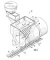
- FIG. 1is a perspective view of an automated packaging apparatus according to the present invention.
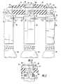
- FIG. 2is a partial exploded assembly drawing of a plurality of rotary slats and stationary spacers on a support shaft.
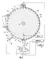
- FIG. 3is a sectional view of the apparatus taken along line 3 — 3 of FIG. 1 .
- FIG. 4is a sectional view taken along line 4 — 4 of FIG. 3 and illustrating a positive count pill delivery path between a rotary slat and a container.
- FIG. 5is a partial view of FIG. 4 illustrating the release of a pill from a rotary slat.
- FIG. 6is a partial perspective view of the apparatus shown with a restraining blanket removed to illustrate the structure of a plurality of spaces.
- FIG. 6Ais a sectional view taken along line 6 A— 6 A of FIG. 6 and illustrating the shape of the spacers according to one embodiment.
- FIG. 7is a perspective view of a drive device for one of the rotary slats.
- FIG. 7Ais a sectional view taken along line 7 A— 7 A of FIG. 7 and illustrating the frustoconical shape of the drive wheels.
- FIG. 7Bis a sectional view taken along line 7 B— 7 B of FIG. 7 A.
- FIG. 8is an end view of the conveyor illustrating a movable pill chute according to one embodiment of the invention.
- FIG. 9is a cutaway perspective view illustrating the common shaft and a pair of clamping blocks from which the shaft is cantilevered.
- the present inventionis directed to an automated rotary slat packaging apparatus 10 which delivers pills 11 from a reservoir 12 into a container 35 .
- pillis used herein throughout but the term is not intended to be limiting and includes any discrete articles of the type used in the pharmaceutical industry or otherwise including, but not limited to, capsules, caplets, gelcaps and tablets.
- the receiving container 35although illustrated as a bottle throughout, is not limited thereto and can be any one of a number of configurations which provides an opening for receiving discrete articles therein, such as pouches or boxes.
- the automated packaging apparatus 10includes the reservoir 12 , a plurality of rotary slats 15 , a plurality of stationary spacers 50 , a plurality of counting devices 65 , and a conveyor system 30 .
- the apparatusalso includes a plurality of drive devices 36 and a controller 45 .
- a filling station 33is defined by a respective rotary slat 15 , counting device 65 , and an aligned container or bottle 35 .
- the apparatusincludes a plurality of filling stations 33 corresponding to the number of rotary slats 15 .
- each of the rotary slats 15 and the stationary spacers 50are individually removable from and assembleable on a support shaft 60 .
- the support shaft 60is preferably cantilevered from one end by a pair of clamping blocks 61 , illustrated schematically in FIG. 9, so that the other end remains generally unsupported (a cover may be removably secured to the free end).
- the slats 15 and spacers 50can easily be removed over the free end of the support shaft 60 .
- the assembly and disassembly flexibility provided by the inventionis such that the apparatus 10 can accommodate different numbers of filling stations (such as the ten illustrated) by increasing or decreasing the number of rotary slats on the shaft 60 . Further, if one of the components malfunctions, the other filling stations 33 remain operable and, advantageously, modular repair or replacement of only the problematic slat or spacer can improve repair costs and decrease machine downtime.
- Each of the rotary slats 15 and stationary spacers 50 illustrated in FIG. 2includes aligned apertures 15 a , 50 a for individually receiving the support shaft 60 therethrough.
- each of the rotary slats 15is configured the same to allow full interchangeability of position in the apparatus and along the support shaft 60 .
- each of the stationary spacers 50is configured the same for interchangeability.
- FIGS. 6 and 6AAn alternative embodiment of the spacer 52 is illustrated in FIGS. 6 and 6A.
- Each of these spacers 52has a generally quarter-circle shape which fits in place between the rotary slats 15 for the portion of the path of travel of the rotary slats which extends through the reservoir 12 . Accordingly, it is not necessary for the shaft 60 to extend through the spacers 52 and the spacers can be easily removed (after removal of the reservoir 12 ) in a radial direction.
- the spacers 52define a peaked cross-section, best seen in FIG. 6A, so that pills 11 in the reservoir 12 will be more easily channeled into the rotary slats 15 .
- Each rotary slat 15is operably connected with a separate drive device 36 so that it can be operated individually, or separate from, the other rotary slats 15 .
- a separate drive device 36is illustrated in FIGS. 2 and 3, the remainder of the motors are positioned serially along the backside of the rotary slats 15 aligned with the illustrated motor.
- the drive devices 36can all be supported on a common rack or support member 41 . In this configuration, if it is desired to package a different type of pill and the slats 15 and/or spacers 50 are changed out for others, the drive devices 36 can also be easily changed, if necessary, by removing the support member 41 (with the drive devices attached) and substituting another support member having the new drive devices thereon.
- FIGS. 7, 7 A and 7 BA particularly advantageous drive device 36 is illustrated in FIGS. 7, 7 A and 7 B.
- the drive device 36includes a drive motor 40 which is rotatable in a given direction.
- One or more belts and pulleys(or other conventional power transmission equipment) are used to couple the drive motor 40 to first and second drive shafts 42 , 43 .
- the drive shafts 42 , 43are coupled to the drive motor 40 to rotate in opposite directions and at the same speed.
- Each of the drive shafts 42 , 43is fitted with a drive wheel 47 .
- the drive wheels 47have a tapered, frustoconical shape so as to define a drive surface 48 .
- the drive wheels 47are formed of an elastomeric traction material such as hard rubber.
- the rotary slats 15are also provided with a pair of frustoconical drive surfaces 49 for engagement by the drive surfaces 48 of the drive wheels 47 . Accordingly, rotation of the drive motor 40 causes the drive shafts 42 , 43 to rotate which in turn causes the respective rotary slat 15 to rotate.
- the conical angles of the guide surfaces 48 and 49are determined based on the respective diameters of the drive wheel 47 and the rotary slat 15 such that there is no scuffing or sliding of the drive wheel on the surface of the slat. It would be further appreciated that the conical angles as illustrated are exaggerated (given the illustrated sizes of the drive wheels 47 and rotary slat 15 ) to facilitate a better understanding of the invention.
- An actuator 46such as a pneumatic cylinder, is provided in the frame of the apparatus 10 .
- the actuator 46is capable of retracting the drive device 36 relative to the rotary slat 15 so that a changeover of rotary slats can be easily effected by withdrawing the wheels 47 from the slat.
- the actuatorcan advance the drive wheels 47 and press the wheels against the rotary slat with a substantially uniform force. Accordingly, if there is any wear between the respective drive surfaces 48 , 49 , the actuator will maintain a constant pressure (such as by incrementally advancing the wheels 47 ) to compensate for the wear and prevent slippage.
- the functions of disengaging the drive device 36 from the rotary slat 15 and of maintaining pressure on the drive wheels 47could be performed by separate and different devices, however, such as a mechanical linkage for the former and a compression spring for the latter.
- Another advantage of the drive device 36 according to this embodiment of the inventionis that the lateral force applied to a rotary slat 15 by one of the drive wheels 47 is balanced by the lateral force of the other wheel of the device. In other words, the net resultant bending moment applied to the rotary slat 15 is zero.
- the bearings used for supporting the rotary slats 15 on the support shaft 60need not be of a type which are designed for resisting bending moments. With the present invention, it is even possible to use a plain bearing configuration where the inner surfaces of the apertures 15 a ride directly on the support shaft 60 with no intervening rolling elements.
- FIG. 7 BA preferred arrangement for the drive devices 36 is illustrated in FIG. 7 B.
- the relatively narrow spacing between the rotary slats 15may not provide sufficient room for the adjacent drive wheels 47 of two adjacent drive devices 36 to be positioned side-by-side.
- the drive devices 36can be positioned alternately in separate rows across the apparatus.
- the drive shafts 42 , 43 (and the drive wheels 47 ) of one alternating plurality of drive devices 36are positioned in a plane separate from the drive shafts of the other alternating plurality of drive devices to allow room for both sets of drive wheels 47 .
- the spacer 50 of FIGS. 2 and 3defines a cut-out portion 51 to provide access for the drive wheels 47 against the adjacent rotary slats 15 .
- a single drive wheel 47could alternatively contact the generally cylindrical outer surface of the respective rotary slat 15 . If the latter is the case, the cylindrical outer surface of the rotary slat 15 can define a cross section having recessed contour such that the drive wheel 47 engages only the higher portions on either side of the recessed portion.
- the drive motor 40be a variable speed unit, such as a stepper motor, the speed being controlled by the central controller 45 .
- the unitcan have at least a first and second drive speed.
- the first drive speedwill operate during the initial portion of the pill filling operation.
- the drive motor 40Upon delivery of a predetermined number of pills 11 to the container 35 , the drive motor 40 will slow to finish the filling operation and prevent underfill or overfill of the container.
- each rotary slat 15rotates in a clockwise direction defining an arcuate delivery path from a first, pill capture position at an opening in the reservoir shown generally at position 20 to a second, release position, generally about 180-270 degrees away from the first position 20 , shown as position 25 , where the pill is released.
- the rotary slatincludes a plurality of serially aligned pill receptacles 18 .
- the receptacles 18are sized and configured to receive one pill 11 therein such that, when properly seated, the top of the pill is substantially flush with the outer peripheral edge of the rotary slat 15 .
- the stationary spacer 50can also be configured with raised or crowned peripheral edges, similar to the spacer 52 illustrated in FIG. 6A, to further direct pills 11 into the rotary slats 15 .
- the rotary slats 50can include a plurality of air passages 56 in fluid communication with a corresponding one of the pill receptacles 18 .
- the wheel-like spacer 50includes an air passage 55 which communicates with the rotary slat air passage 56 when the receptacle is in the release position 25 .
- the apparatus 10includes a pressurized air supply which is directed through the stationary spacer passage 55 and the aligned rotary slat passage 56 when the receptacle 18 is at the release position 25 .
- the receptacle 18includes a channel 56 a which is formed in the receptacle 18 intermediate the air passage 56 such that pressurized air forces or assists in the ejection of the pill 11 from the receptacle 18 at the predetermined release point 25 .
- the air supplycan be introduced or plumbed into the air passages 55 , 56 in many different ways.
- a central air supplycan be positioned at one end of the support shaft 60 and a main air supply channel can be formed therein.
- Each or selected ones of the stationary slats 50can then include channels connecting the main air passage in the shaft 60 to the ejection air passage 55 .
- the rotary slat 15advances to the release position 25 , and the receptacle air passage 56 aligns with the stationary spacer air passage 55 .
- a “puff” of pressurized airis injected into the pill receptacle 18 assisting in the release of the pill 11 from the receptacle. Further and advantageously, this burst of air can clean the rotary slat 15 and remove particulate matter such as pill dust from the receptacle 18 .
- FIGS. 1 and 3illustrate further preferred features of the apparatus.
- a brush bar 22which rotates against the direction of rotation of the rotary slats 15 , assists in seating the captured pill 11 in the receptacle 18 and also diverts additional pills away from the delivery path (see also FIG. 6 ).
- a cover 80is positioned adjacent the brush bar 22 to assist in maintaining the pill 11 in place during travel to the filling station.
- the cover 80is sized and configured to yield a one pill clearance relative to the top surface of the rotary slat 15 .
- the cover 80can also facilitate cleanliness by preventing environmental debris from entering the delivery path or contacting the captured pill 11 .
- the cover 80is a flexible thin material such as a Teflon® blanket.
- the reservoir 12employs a conventional vibrator to assist in the insertion of the pills 11 into the rotary slats 15 .
- the apparatusalso includes a conveyor system 30 to automatically move the containers 35 to and away from the filling stations 33 at the proper time intervals.
- the conveyor system 30employs a screw auger 31 which advances the containers 35 to the corresponding filling stations 33 .
- many alternative conveyor systemssuch as a belt (see FIG. 8 ), a flat linked chain, or even a vibratory floating feed system) can also be employed with the apparatus of the present invention.
- the conveyor system 30is controlled by the central controller 45 .
- the controller 45will direct the filled containers out of the filling stations and direct unfilled containers thereto. However, if any one container is determined to be underfilled (as will be discussed further below) the controller 45 will not advance the containers (or at least that container) and direct the individual rotary slat at the underfilled station to rotate forward, thereby advancing an increased number of released pills to fill the underfilled container 35 . The controller 45 then will release the container(s) and cause the conveyor system 30 to advance the container(s) out of the filling station(s).
- the rotary slats 15are all rotated at the same time and speed to begin the filling operation and slowed at the same time to a slower fill rate at a count close to the desired full count. Because the rotary slats 15 are all rotated concurrently the slats should fill the containers 35 at substantially the same rate, increasing throughput for the filling operation.
- the positive count packaging apparatus 10includes a counting device 65 associated with each filling station 33 .
- the device 65is sized and configured to extend between the rotary slat 15 and the opening in the container. Further preferably, the device 65 will be positioned substantially adjacent the opening in a chute 66 above the container 35 so that any pill which travels through the device will enter the container without falling outside the delivery path. It will be appreciated that the chute 66 is not always necessary and may be omitted if the tops of the containers 35 are sufficiently close to the rotary slats 15 .
- the counting devices 65can all be mounted together with the chutes 60 to correspond with the spacing of the rotary slats 15 on a stationary support member 67 which extends across the width of the rotary slats 15 .
- the counting device support member 67can be easily changed out and substituted by a different support member having counting devices and chutes mounted thereon when it is desired to package differently shaped pills or for any other reason to use different slats.
- an elongated chutecan be positioned for feeding pills 11 from multiple rotary slats 15 into a single container.
- the individual drive devices for those slatscan be mechanically or electrically linked together or the slats can be mechanically fastened together and driven by a single drive device. Further, an additional fully independent rotary slat can feed into the same chute to slowly complete the desired count after the majority of the count has been filled by the linked slats.
- a movable chute 68is illustrated in FIG. 8 for shuttling between two rows of containers 35 on separate belt conveyors 30 .
- the movable chute 68has a width such that pills 11 will always be collected by the chute, regardless of its position. However, by moving the chute 68 back and forth as illustrated, the apparatus can first fill one container 35 and then immediately begin to fill a neighboring container. Thus, the rotary slats 15 can rotate continuously without any “downtime” while waiting for a single conveyor to advance the row of containers.
- a counting device 65although not illustrated in FIG. 8, is positioned to count every pill 11 which is dropped. The counting device 65 could, for example, be positioned at the exit of the chute 68 , or even within the chute.
- a preferred counting device 65is illustrated in FIG. 5 and includes an infrared light source 70 and a light receiver 71 positioned substantially opposite the light source 70 across the central passage of the device.
- the light source 70generates a substantially planar light beam 72 which is detected by the opposing light receiver 71 .
- the light receiver 71transmits a signal which increases the count in the controller 45 .
- the number of interruptionscorresponds to the number of pills 11 which have been introduced into the container 35 .
- a pill 11is released (a process which may be assisted by a puff of air) from the receptacle 18 into the device 65 .
- the pill 11falls through the central passage of the device 65 interrupting the light beam 72 extending thereacross causing the counter to increase each time the beam is interrupted.
- the device 65can also include an audible or visible alarm 62 at each filling station 33 , such as an LED (light emitting diode) which is activated upon determination of a problem such as an incorrect count in the respective container 35 .
- an audible or visible alarm 62at each filling station 33 , such as an LED (light emitting diode) which is activated upon determination of a problem such as an incorrect count in the respective container 35 .
- a central alarmcan be provided by the controller 45 . The operator can manually rectify the problem such as by adding or removing pills to provide an accurate count.
- the controller 45will automatically correct for underfill situations by rotating the rotary slat 15 a predetermined-angle and advancing more pills into the container 35 .
- the controller 45can accumulate information about each filling station 33 and indicate that maintenance needs to be performed for respective filling stations, such as when count problems exist more than a statistically valid number of times within a predetermined period. This can facilitate efficient operation of the apparatus. For example, an underfill or slow fill situation may indicate improper alignment of the counting device at the filling station, a malfunctioning drive motor, plugged receptacles, and the like.
- the controller 45can also compare the counts in the containers 35 as amongst filling stations 33 to determine any irregularities therebetween.
- a plurality of samecan be employed to generate a series of beams at different positions across the delivery path for system redundancy and to determine and statistically compare the average time of beam interruption.
- the elapsed time between beam interruptionscan be used to determine if an odd shaped, shattered or otherwise undersized pill is being delivered to the container.
- various other counting devicescould be used including laser sensors and mechanical trip switches.
- pills 11are fed into a reservoir 12 .
- Containers 35are advanced along a travel path defined by the conveyor system 30 and stopped at respective filling stations 33 .
- the rotary slats 15are rotated at the same time and speed into an opening 13 in the reservoir 12 (such as at a lower portion of the reservoir) to capture a pill in each of the receptacles 18 of each of the slats 15 at position 20 .
- the rotary slat 15continues forward in a clockwise direction to define an arcuate travel path for the pill.
- the rotary slat 15is then engaged by the brush bar 22 rotating in a counter clockwise direction at the top of the arc.
- the brush bar 22is sized and configured to contact the exposed outer surface of the rotary slat 15 to ensure that the pills 11 are properly seated in the respective receptacles 18 and to divert any excess pills therefrom.
- the pill 11remains captured in the receptacle 18 and the exposed edge is covered by the cover 80 which extends until the release position at the bottom of the arc, position 25 .
- the pill 11is released and pulled by gravitational forces through the counting device 65 .
- the pillis also forced by a burst of air into the delivery path defined between the rotary slat 15 and the opening of the container 35 .
- the pill 11falls through the counting device 65 it interrupts the light beam 72 generated by the light source 70 extending across the passage of the device 65 . The interruption is sensed by the receiver 71 and causes a corresponding signal to indicate the current count of pills delivered into the container.
- the rotation of the rotary slats 15is substantially constant during the above described sequence.
- the controller 45optionally slows the speed of the rotary slats 15 to help prevent overfilling of the containers.
- each containerwill be filled with the same count at the same time.
- the rotary slats 15are then halted and wait for the next group of containers to advance. However, if a count is determined to be incorrect, as stated above, an alert will occur and the controller will individually advance any rotary slat to automatically correct for any underfilled container. Once all containers are correctly filled, or corrective measures taken, the filled containers are advanced out of the filling stations and unfilled containers are advanced therein.
Landscapes
- Engineering & Computer Science (AREA)
- Mechanical Engineering (AREA)
- Basic Packing Technique (AREA)
Abstract
Description
Claims (8)
Priority Applications (3)
| Application Number | Priority Date | Filing Date | Title |
|---|---|---|---|
| US09/640,970US6269612B1 (en) | 1998-05-20 | 2000-08-17 | Positive count rotary slat packaging apparatus and related methods |
| US09/876,342US6401429B2 (en) | 1998-05-20 | 2001-06-07 | Positive count rotary slat packaging apparatus and related methods |
| US10/119,500US6505460B2 (en) | 1998-05-20 | 2002-04-10 | Positive count rotary slat packaging apparatus and related methods |
Applications Claiming Priority (2)
| Application Number | Priority Date | Filing Date | Title |
|---|---|---|---|
| US09/082,137US6185901B1 (en) | 1998-05-20 | 1998-05-20 | Positive count rotary slat packaging apparatus and related methods |
| US09/640,970US6269612B1 (en) | 1998-05-20 | 2000-08-17 | Positive count rotary slat packaging apparatus and related methods |
Related Parent Applications (2)
| Application Number | Title | Priority Date | Filing Date |
|---|---|---|---|
| US09/082,137ContinuationUS6185901B1 (en) | 1998-05-20 | 1998-05-20 | Positive count rotary slat packaging apparatus and related methods |
| US09/082,137DivisionUS6185901B1 (en) | 1998-05-20 | 1998-05-20 | Positive count rotary slat packaging apparatus and related methods |
Related Child Applications (2)
| Application Number | Title | Priority Date | Filing Date |
|---|---|---|---|
| US09/640,927DivisionUS6266946B1 (en) | 1998-05-20 | 2000-08-17 | Positive count rotary slat packaging apparatus and related methods |
| US09/876,342DivisionUS6401429B2 (en) | 1998-05-20 | 2001-06-07 | Positive count rotary slat packaging apparatus and related methods |
Publications (1)
| Publication Number | Publication Date |
|---|---|
| US6269612B1true US6269612B1 (en) | 2001-08-07 |
Family
ID=22169301
Family Applications (5)
| Application Number | Title | Priority Date | Filing Date |
|---|---|---|---|
| US09/082,137Expired - Fee RelatedUS6185901B1 (en) | 1998-05-20 | 1998-05-20 | Positive count rotary slat packaging apparatus and related methods |
| US09/640,970Expired - LifetimeUS6269612B1 (en) | 1998-05-20 | 2000-08-17 | Positive count rotary slat packaging apparatus and related methods |
| US09/640,927Expired - LifetimeUS6266946B1 (en) | 1998-05-20 | 2000-08-17 | Positive count rotary slat packaging apparatus and related methods |
| US09/876,342Expired - Fee RelatedUS6401429B2 (en) | 1998-05-20 | 2001-06-07 | Positive count rotary slat packaging apparatus and related methods |
| US10/119,500Expired - Fee RelatedUS6505460B2 (en) | 1998-05-20 | 2002-04-10 | Positive count rotary slat packaging apparatus and related methods |
Family Applications Before (1)
| Application Number | Title | Priority Date | Filing Date |
|---|---|---|---|
| US09/082,137Expired - Fee RelatedUS6185901B1 (en) | 1998-05-20 | 1998-05-20 | Positive count rotary slat packaging apparatus and related methods |
Family Applications After (3)
| Application Number | Title | Priority Date | Filing Date |
|---|---|---|---|
| US09/640,927Expired - LifetimeUS6266946B1 (en) | 1998-05-20 | 2000-08-17 | Positive count rotary slat packaging apparatus and related methods |
| US09/876,342Expired - Fee RelatedUS6401429B2 (en) | 1998-05-20 | 2001-06-07 | Positive count rotary slat packaging apparatus and related methods |
| US10/119,500Expired - Fee RelatedUS6505460B2 (en) | 1998-05-20 | 2002-04-10 | Positive count rotary slat packaging apparatus and related methods |
Country Status (1)
| Country | Link |
|---|---|
| US (5) | US6185901B1 (en) |
Cited By (18)
| Publication number | Priority date | Publication date | Assignee | Title |
|---|---|---|---|---|
| US6505460B2 (en) | 1998-05-20 | 2003-01-14 | Aylward Enterprises, Inc. | Positive count rotary slat packaging apparatus and related methods |
| US6568151B2 (en)* | 2001-02-07 | 2003-05-27 | Kalish, Inc. | Conveyor for use in contamination sensitive equipment |
| US6681550B1 (en) | 2002-08-13 | 2004-01-27 | Aylward Enterprises, Inc. | Apparatus and methods for filling containers with pills |
| US20050077313A1 (en)* | 2002-08-21 | 2005-04-14 | Aylward Enterprises, Inc. | Method of delivering pills through a feeder tube |
| US20060096656A1 (en)* | 2004-11-05 | 2006-05-11 | Pharma Tool Corporation | Method and apparatus for orienting articles |
| US7225597B1 (en)* | 2005-12-23 | 2007-06-05 | Qem, Inc. | Machine to automate dispensing of pills |
| US20070157548A1 (en)* | 2005-12-23 | 2007-07-12 | Qem, Inc. | Method of dispensing pills from a movable platen |
| US20070289660A1 (en)* | 2006-06-01 | 2007-12-20 | John Thomas Aylward | Vacuum Apparatus and Methods for Handling Pills |
| US20090044495A1 (en)* | 2007-08-09 | 2009-02-19 | Aylward Enterprises, Inc. | Packaging Apparatus for Handling Pills and Associated Method |
| US20090094947A1 (en)* | 2007-08-09 | 2009-04-16 | Aylward Enterprises, Llc | Packaging Apparatus for Handling Pills and Associated Method |
| US20090255948A1 (en)* | 2008-04-14 | 2009-10-15 | Loris Bassani | Container filling machine having vibration trays |
| US20100115892A1 (en)* | 2008-11-07 | 2010-05-13 | Aylward Enterprises, Llc | Packaging apparatus for handling pills and associated method |
| US20100133066A1 (en)* | 2008-12-02 | 2010-06-03 | Count Lab, Inc. | Discrete article spacing apparatus for vibration trays |
| US7956623B2 (en) | 2007-02-16 | 2011-06-07 | Countlab, Inc | Container filling machine |
| US10577186B2 (en) | 2011-08-18 | 2020-03-03 | Countlab, Inc. | Container filling machine |
| US10583941B2 (en) | 2017-10-13 | 2020-03-10 | Rxsafe Llc | Universal feed mechanism for automatic packager |
| US11220361B2 (en) | 2018-10-12 | 2022-01-11 | Aylward Enterprises, Llc | Packaging apparatus for handling pills and associated method |
| US11305908B2 (en) | 2019-09-20 | 2022-04-19 | Aylward Enterprises, Llc | Tablet counter and packaging module and associated method |
Families Citing this family (52)
| Publication number | Priority date | Publication date | Assignee | Title |
|---|---|---|---|---|
| AUPP656498A0 (en)* | 1998-10-19 | 1998-11-05 | Bosspak Pty Ltd | An apparatus for filling containers with discrete articles |
| US6452133B1 (en)* | 1999-07-26 | 2002-09-17 | Alza Corporation | Apparatus and methods for alternating laser treatment of pharmaceutical dispensers |
| US6345487B1 (en)* | 1999-10-15 | 2002-02-12 | Luciano Packaging Technologies, Inc. | High quality control tablet filler device |
| US6739111B2 (en)* | 2001-09-06 | 2004-05-25 | The Boeing Company | Automated filling machine and associated method |
| ES2261809T3 (en)* | 2002-04-23 | 2006-11-16 | Robert Bosch Gmbh | PROCEDURE FOR THE TRANSFER OF ARTICLES FROM A BOOKING INSTALLATION TO ACCOMMODATIONS OF A CONTAINER. |
| ITBO20020313A1 (en)* | 2002-05-21 | 2003-11-21 | Ima Spa | UNIT FOR FILLING CONTAINERS WITH PRODUCTS, IN PARTICULAR PHARMACEUTICAL ITEMS |
| US7650732B2 (en)* | 2002-12-06 | 2010-01-26 | Pearson Medical Technologies, Inc. | Drug packaging machine & printing software for same |
| ES2242475B2 (en)* | 2002-12-18 | 2007-02-01 | Universidad De La Rioja | SUPPLY-DOSER OF TABLETS TO PACKAGING FOR THE FOOD INDUSTRY. |
| US8141330B2 (en)* | 2004-05-20 | 2012-03-27 | KNAPP Logistics Automation, Inc. | Systems and methods of automated tablet dispensing, prescription filling, and packaging |
| GB0415951D0 (en)* | 2004-07-16 | 2004-08-18 | Meadwestvaco Packaging Systems | A method for identifying abnormal operation of a machine and an apparatus therefor |
| US7255247B2 (en)* | 2004-12-02 | 2007-08-14 | Aylward Enterprises, Inc. | Apparatus and methods for handling pills |
| JP5208747B2 (en)* | 2005-09-20 | 2013-06-12 | カンパテンツ ベー フェー | Method and apparatus for filling containers |
| US7795556B1 (en) | 2006-09-14 | 2010-09-14 | Dean Edward T | Packaging apparatus |
| ITBO20070179A1 (en)* | 2007-03-14 | 2008-09-15 | Marchesini Group Spa | DEVICE FOR THE COLLECTION OF ITEMS FROM A POWER STATION AND FOR INSERTING THEMSELVES INTO A CONTAINER |
| US7861845B1 (en) | 2007-04-09 | 2011-01-04 | Robin Lapointe | Roller sorter system |
| US8622196B1 (en) | 2007-04-09 | 2014-01-07 | Robin Lapointe | Roller sorter system |
| US8146331B2 (en)* | 2009-01-15 | 2012-04-03 | Sabrie Soloman | Automated packaging, inspection, verification, and counting apparatus |
| TWI376474B (en)* | 2009-02-02 | 2012-11-11 | Ind Tech Res Inst | System and method for real time monitoring and control of compressor oil return |
| NL2003428C2 (en) | 2009-09-02 | 2011-03-03 | Cremer Speciaalmachines B V | FILLING DEVICE. |
| US20110113727A1 (en)* | 2009-11-18 | 2011-05-19 | Bonner Kevin B | Custom Prepackaging Method and Apparatus |
| EP2394626A1 (en)* | 2010-06-09 | 2011-12-14 | JVM Co., Ltd. | Medicine dispenser, method of discharging medicine, and automatic medicine packing machine including the dispenser |
| IT1401847B1 (en)* | 2010-10-14 | 2013-08-28 | Marchesini Group Spa | METHOD AND SYSTEM TO TRANSFER FRAGILE CONTAINERS FROM A CONTAINER TO A PACKAGING MACHINE |
| IT1401848B1 (en)* | 2010-10-14 | 2013-08-28 | Marchesini Group Spa | METHOD AND DEVICE FOR TRANSFERRING FRAGILE CONTAINERS FROM A PACKAGING MACHINE TO CONTAINERS |
| JP5421310B2 (en)* | 2011-03-04 | 2014-02-19 | 中洲電機株式会社 | Drug sorting device |
| ITBO20110708A1 (en)* | 2011-12-14 | 2013-06-15 | Marchesini Group Spa | APPARATUS FOR ADJUSTING THE RELEASE OF TABLETS IN THE HOLLOWS OF A THERMOFORMED TAPE |
| CN103395512B (en)* | 2013-08-28 | 2015-04-01 | 杭州迈可思法电气工程有限公司 | Rotating drum-type particle counting machine |
| EP2910478B1 (en)* | 2014-02-22 | 2016-04-27 | Harro Höfliger Verpackungsmaschinen GmbH | Metering device for tablets and method for metering tablets |
| DE102014113248A1 (en)* | 2014-09-15 | 2016-03-17 | Focke & Co. (Gmbh & Co. Kg) | Method and device for handling elongate objects |
| US10370135B2 (en) | 2015-02-10 | 2019-08-06 | 3605329 Canada Inc. | Belt sorting system |
| EP3313244B1 (en)* | 2015-06-23 | 2021-07-21 | Société des Produits Nestlé S.A. | Capsule dispensing device |
| CN105109722B (en)* | 2015-08-27 | 2025-08-15 | 宁波捷碧医疗科技有限公司 | Full-automatic medicine distributing and supplying system and automatic solid medicine separating method |
| CN105523239B (en)* | 2015-11-26 | 2017-12-22 | 徐州盛和木业有限公司 | A kind of robot scaler |
| CN106218962B (en)* | 2016-07-25 | 2018-09-04 | 杭州电子科技大学 | Headband racking machine |
| KR20180105804A (en)* | 2017-03-16 | 2018-10-01 | (주)제이브이엠 | Blister Packing Device and Packing Method for Blister Pack |
| DE102017121560A1 (en)* | 2017-09-18 | 2019-03-21 | Nils Dickfeld | Feeding device for placing products on a conveyor belt |
| CN107985696A (en)* | 2017-11-05 | 2018-05-04 | 安徽金三环金属科技有限公司 | Intelligent horizontal dripping pill bottle placer |
| DE102017130500A1 (en)* | 2017-12-19 | 2019-06-19 | Wolfgang Kolodziej | Device for separating and aligning stick-shaped piece goods |
| US11155378B2 (en) | 2019-04-05 | 2021-10-26 | Blue Sky Ventures? (Ontario) Inc. | Gating system for accumulating items and related filling machine and methods |
| US12071286B1 (en) | 2019-07-11 | 2024-08-27 | Express Scripts Strategic Development, Inc. | Cap assembly for a medication container |
| US12012276B2 (en) | 2019-07-11 | 2024-06-18 | Express Scripts Strategic Development, Inc. | Cap assembly for a medication container |
| US11827442B1 (en) | 2019-07-11 | 2023-11-28 | Express Scripts Strategic Development, Inc. | Cap assembly for a medication container |
| US11673698B2 (en)* | 2020-03-10 | 2023-06-13 | Blue Sky Ventures (Ontario) Inc. | Continuous motion filling system and filling machine and methods |
| CN111591510A (en)* | 2020-05-29 | 2020-08-28 | 发泰(天津)科技有限公司 | A jet-type pill filling device |
| CN111847003A (en)* | 2020-08-17 | 2020-10-30 | 诸葛嘉 | Accurate metering device of medical medicine |
| US11787578B2 (en)* | 2020-09-25 | 2023-10-17 | Express Scripts Strategic Development, Inc. | Cleaner assembly for an automated dispensing device |
| CN112124653B (en)* | 2020-09-29 | 2024-12-31 | 苏州医疗用品厂有限公司 | Tube needle sorting equipment |
| US11833113B2 (en) | 2021-04-26 | 2023-12-05 | Express Scripts Strategic Development, Inc. | Cap assembly for a medication container |
| CN113430103B (en)* | 2021-06-29 | 2023-10-10 | 杭州励嘉健康管理咨询有限公司 | Gene detection sampler convenient to use |
| US20240238162A1 (en)* | 2021-08-27 | 2024-07-18 | Multiply Labs Inc. | System, method, and apparatus facilitating assembly of a capsule |
| CN115057061A (en)* | 2022-06-20 | 2022-09-16 | 苏州金万佳塑业有限公司 | Counting and packaging equipment for sterile preservation boxes and working method thereof |
| US12365011B2 (en) | 2022-07-06 | 2025-07-22 | Sani-Matic, Inc. | Slat cleaning apparatus |
| CN116654397B (en)* | 2023-06-28 | 2024-04-09 | 威海家和生物科技有限公司 | Health food packaging equipment |
Citations (18)
| Publication number | Priority date | Publication date | Assignee | Title |
|---|---|---|---|---|
| US1383623A (en) | 1920-05-08 | 1921-07-05 | James E Groves | Machine for feeding pellets into containers |
| US1824432A (en) | 1928-06-08 | 1931-09-22 | E D Anderson Inc | Packing machine |
| US1839327A (en) | 1928-08-22 | 1932-01-05 | Thermal Engineering Corp | Distributor for leers |
| AU2055834A (en) | 1934-12-12 | 1936-01-09 | Marconis Wireless Telegraph Company Limited | Improvements in or relating to thermionic valve circuit arrangements and to radio and like modulated carrier wave receivers |
| US2479667A (en) | 1944-12-18 | 1949-08-23 | Valentine Lab Inc | Counting machine for tablets and the like |
| US2585558A (en) | 1946-12-05 | 1952-02-12 | Eino E Lakso | Article counting and filling |
| US2845759A (en)* | 1955-09-26 | 1958-08-05 | Us Automatic Box Machinery Co | Method of and machine for filling bottles with capsules |
| US3028713A (en) | 1958-10-02 | 1962-04-10 | Kennedy Edward | Article counting and loading machine |
| US3139713A (en) | 1962-03-05 | 1964-07-07 | Merrill | Pill counting and filling mechanism |
| US3225513A (en) | 1961-11-01 | 1965-12-28 | Multicup Automation Company In | Automatic packaging machine |
| US3387695A (en) | 1967-01-10 | 1968-06-11 | Lakso Company Inc | Inspection of moving discrete particles |
| US3925960A (en)* | 1974-04-18 | 1975-12-16 | Lakso Company Inc | Article counting and filling machine |
| US3979878A (en) | 1974-10-16 | 1976-09-14 | Berney Joseph C | Container accumulating apparatus |
| US4265072A (en)* | 1978-07-21 | 1981-05-05 | Alwin Egli | Apparatus for charging receptacles with items of like size and shape |
| US4674259A (en) | 1986-08-20 | 1987-06-23 | Package Machinery Company | Container filling machine |
| US4677283A (en) | 1986-08-26 | 1987-06-30 | H. G. Kalish Inc. | Device for counting and loading small items into containers |
| US5515668A (en) | 1993-09-03 | 1996-05-14 | Simplimatic Engineering Company | Laning conveyor with changeover system |
| CA2203856A1 (en) | 1997-04-28 | 1998-10-28 | Kalish Canada Inc. | Apparatus for dispensing tablets |
Family Cites Families (15)
| Publication number | Priority date | Publication date | Assignee | Title |
|---|---|---|---|---|
| US422364A (en) | 1890-03-04 | Capsule-receiving frame | ||
| US2094460A (en)* | 1935-03-21 | 1937-09-28 | Beech Nut Packing Co | Box filling machine |
| US3354607A (en)* | 1965-05-20 | 1967-11-28 | Lakso Company Inc | Slat type counting and filling machine |
| US3417542A (en)* | 1965-11-26 | 1968-12-24 | Merrill Machinery Company | Desiccant capsule feeding machine |
| US3677437A (en) | 1970-03-27 | 1972-07-18 | John S Haigler | Pill counting apparatus having chute shifting on predetermined count |
| IT988340B (en) | 1970-11-12 | 1975-04-10 | List H | DEVICE FOR ORDERING COUNT RE AND TRANSFERRING DOSAGE CAPSULES AND SIMILAR UNIFORM BODIES FOR MACEUTICAL USE |
| US3782590A (en) | 1972-05-18 | 1974-01-01 | G Apfel | Pill counting machine |
| US3837139A (en) | 1973-07-05 | 1974-09-24 | H Rosenberg | Apparatus for handling and counting pills and the like |
| GB1506329A (en) | 1975-05-09 | 1978-04-05 | Fahr Ag Maschf | Combine harvesters |
| US4017003A (en)* | 1975-12-18 | 1977-04-12 | The Lakso Company, Incorporated | Article dispensing machine |
| US4094129A (en) | 1977-08-01 | 1978-06-13 | Hans List | Counting and filling apparatus for tablets, dragees or similar elements |
| WO1994015859A1 (en) | 1993-01-04 | 1994-07-21 | Shaw Thomas J | Automatic pill dispensing apparatus |
| US5522512A (en) | 1994-05-09 | 1996-06-04 | Merck & Co., Inc. | System and method for automatically feeding, inspecting and diverting tablets for continuous filling of tablet containers |
| US5463839A (en) | 1994-08-04 | 1995-11-07 | The Lakso Company | Apparatus for packaging a predetermined quantity of objects and a counting device therefor |
| US6185901B1 (en) | 1998-05-20 | 2001-02-13 | Aylward Enterprises, Inc. | Positive count rotary slat packaging apparatus and related methods |
- 1998
- 1998-05-20USUS09/082,137patent/US6185901B1/ennot_activeExpired - Fee Related
- 2000
- 2000-08-17USUS09/640,970patent/US6269612B1/ennot_activeExpired - Lifetime
- 2000-08-17USUS09/640,927patent/US6266946B1/ennot_activeExpired - Lifetime
- 2001
- 2001-06-07USUS09/876,342patent/US6401429B2/ennot_activeExpired - Fee Related
- 2002
- 2002-04-10USUS10/119,500patent/US6505460B2/ennot_activeExpired - Fee Related
Patent Citations (18)
| Publication number | Priority date | Publication date | Assignee | Title |
|---|---|---|---|---|
| US1383623A (en) | 1920-05-08 | 1921-07-05 | James E Groves | Machine for feeding pellets into containers |
| US1824432A (en) | 1928-06-08 | 1931-09-22 | E D Anderson Inc | Packing machine |
| US1839327A (en) | 1928-08-22 | 1932-01-05 | Thermal Engineering Corp | Distributor for leers |
| AU2055834A (en) | 1934-12-12 | 1936-01-09 | Marconis Wireless Telegraph Company Limited | Improvements in or relating to thermionic valve circuit arrangements and to radio and like modulated carrier wave receivers |
| US2479667A (en) | 1944-12-18 | 1949-08-23 | Valentine Lab Inc | Counting machine for tablets and the like |
| US2585558A (en) | 1946-12-05 | 1952-02-12 | Eino E Lakso | Article counting and filling |
| US2845759A (en)* | 1955-09-26 | 1958-08-05 | Us Automatic Box Machinery Co | Method of and machine for filling bottles with capsules |
| US3028713A (en) | 1958-10-02 | 1962-04-10 | Kennedy Edward | Article counting and loading machine |
| US3225513A (en) | 1961-11-01 | 1965-12-28 | Multicup Automation Company In | Automatic packaging machine |
| US3139713A (en) | 1962-03-05 | 1964-07-07 | Merrill | Pill counting and filling mechanism |
| US3387695A (en) | 1967-01-10 | 1968-06-11 | Lakso Company Inc | Inspection of moving discrete particles |
| US3925960A (en)* | 1974-04-18 | 1975-12-16 | Lakso Company Inc | Article counting and filling machine |
| US3979878A (en) | 1974-10-16 | 1976-09-14 | Berney Joseph C | Container accumulating apparatus |
| US4265072A (en)* | 1978-07-21 | 1981-05-05 | Alwin Egli | Apparatus for charging receptacles with items of like size and shape |
| US4674259A (en) | 1986-08-20 | 1987-06-23 | Package Machinery Company | Container filling machine |
| US4677283A (en) | 1986-08-26 | 1987-06-30 | H. G. Kalish Inc. | Device for counting and loading small items into containers |
| US5515668A (en) | 1993-09-03 | 1996-05-14 | Simplimatic Engineering Company | Laning conveyor with changeover system |
| CA2203856A1 (en) | 1997-04-28 | 1998-10-28 | Kalish Canada Inc. | Apparatus for dispensing tablets |
Cited By (34)
| Publication number | Priority date | Publication date | Assignee | Title |
|---|---|---|---|---|
| US6505460B2 (en) | 1998-05-20 | 2003-01-14 | Aylward Enterprises, Inc. | Positive count rotary slat packaging apparatus and related methods |
| US6568151B2 (en)* | 2001-02-07 | 2003-05-27 | Kalish, Inc. | Conveyor for use in contamination sensitive equipment |
| US6681550B1 (en) | 2002-08-13 | 2004-01-27 | Aylward Enterprises, Inc. | Apparatus and methods for filling containers with pills |
| EP1389583A1 (en)* | 2002-08-13 | 2004-02-18 | Aylward Enterprises, Inc. | Apparatus and methods for filling containers with pills |
| US20040128955A1 (en)* | 2002-08-13 | 2004-07-08 | Aylward Enterprises, Inc. | Apparatus and methods for filling containers with pills |
| US6799413B2 (en) | 2002-08-13 | 2004-10-05 | Aylward Enterprises, Inc. | Apparatus and methods for filling containers with pills |
| US20050077313A1 (en)* | 2002-08-21 | 2005-04-14 | Aylward Enterprises, Inc. | Method of delivering pills through a feeder tube |
| US20050189373A1 (en)* | 2002-08-21 | 2005-09-01 | Aylward Enterprises, Inc. | Feeder tube for filling containers with pills |
| US7007821B2 (en) | 2002-08-21 | 2006-03-07 | Aylward Enterprises, Inc. | Method of delivering pills through a feeder tube |
| US7066350B2 (en) | 2002-08-21 | 2006-06-27 | Aylward Enterprises, Inc. | Feeder tube for filling containers with pills |
| US7124912B2 (en)* | 2002-08-21 | 2006-10-24 | Aylward Enterprises, Inc. | Feeder tube for filling containers with pills |
| US20070007693A1 (en)* | 2002-08-21 | 2007-01-11 | Aylward Enterprises, Inc. | Feeder Tube for Filling Containers with Pills |
| US7892473B2 (en) | 2002-08-21 | 2011-02-22 | Aylward Enterprises, Llc | Feeder tube for filling containers with pills |
| US20060096656A1 (en)* | 2004-11-05 | 2006-05-11 | Pharma Tool Corporation | Method and apparatus for orienting articles |
| US7426814B2 (en)* | 2005-12-23 | 2008-09-23 | Qem, Inc. | Method of dispensing pills from a movable platen |
| US7225597B1 (en)* | 2005-12-23 | 2007-06-05 | Qem, Inc. | Machine to automate dispensing of pills |
| US20070157548A1 (en)* | 2005-12-23 | 2007-07-12 | Qem, Inc. | Method of dispensing pills from a movable platen |
| US20070289660A1 (en)* | 2006-06-01 | 2007-12-20 | John Thomas Aylward | Vacuum Apparatus and Methods for Handling Pills |
| US7956623B2 (en) | 2007-02-16 | 2011-06-07 | Countlab, Inc | Container filling machine |
| US20090044495A1 (en)* | 2007-08-09 | 2009-02-19 | Aylward Enterprises, Inc. | Packaging Apparatus for Handling Pills and Associated Method |
| US20090094947A1 (en)* | 2007-08-09 | 2009-04-16 | Aylward Enterprises, Llc | Packaging Apparatus for Handling Pills and Associated Method |
| US20110113730A1 (en)* | 2007-08-09 | 2011-05-19 | Aylward Enterprises, Llc | Packaging apparatus for handling pills and associated method |
| US20090255948A1 (en)* | 2008-04-14 | 2009-10-15 | Loris Bassani | Container filling machine having vibration trays |
| US8006468B2 (en) | 2008-04-14 | 2011-08-30 | Countlab Inc. | Container filling machine having vibration trays |
| US20100115892A1 (en)* | 2008-11-07 | 2010-05-13 | Aylward Enterprises, Llc | Packaging apparatus for handling pills and associated method |
| US8424274B2 (en) | 2008-11-07 | 2013-04-23 | Aylward Enterprises, Llc | Packaging apparatus for handling pills and associated method |
| USRE46910E1 (en) | 2008-11-07 | 2018-06-26 | Aylward Enterprises, Llc | Packaging apparatus for handling pills and associated method |
| US20100133066A1 (en)* | 2008-12-02 | 2010-06-03 | Count Lab, Inc. | Discrete article spacing apparatus for vibration trays |
| US8225925B2 (en) | 2008-12-02 | 2012-07-24 | Countlab Inc. | Discrete article spacing apparatus for vibration trays |
| US10577186B2 (en) | 2011-08-18 | 2020-03-03 | Countlab, Inc. | Container filling machine |
| US10583941B2 (en) | 2017-10-13 | 2020-03-10 | Rxsafe Llc | Universal feed mechanism for automatic packager |
| US11305898B2 (en) | 2017-10-13 | 2022-04-19 | Rxsafe Llc | Universal feed mechanism for automatic packager |
| US11220361B2 (en) | 2018-10-12 | 2022-01-11 | Aylward Enterprises, Llc | Packaging apparatus for handling pills and associated method |
| US11305908B2 (en) | 2019-09-20 | 2022-04-19 | Aylward Enterprises, Llc | Tablet counter and packaging module and associated method |
Also Published As
| Publication number | Publication date |
|---|---|
| US6505460B2 (en) | 2003-01-14 |
| US6266946B1 (en) | 2001-07-31 |
| US20020108356A1 (en) | 2002-08-15 |
| US6185901B1 (en) | 2001-02-13 |
| US6401429B2 (en) | 2002-06-11 |
| US20010045081A1 (en) | 2001-11-29 |
Similar Documents
| Publication | Publication Date | Title |
|---|---|---|
| US6269612B1 (en) | Positive count rotary slat packaging apparatus and related methods | |
| EP1389583B1 (en) | Apparatus and methods for filling containers with pills | |
| USRE46910E1 (en) | Packaging apparatus for handling pills and associated method | |
| CN100506647C (en) | Unit for filling containers with products, in particular, pharmaceutical products | |
| EP0797525B1 (en) | System for feeding articles to blisters of a blister band | |
| US7255247B2 (en) | Apparatus and methods for handling pills | |
| JP3799088B2 (en) | Automatic device for aligning and supplying containers in an aligned state | |
| EP2753545B1 (en) | System and method for packaging dosed quantities of solid drug portions | |
| US7861845B1 (en) | Roller sorter system | |
| US2509069A (en) | Machine for sorting, counting, and packaging medicinal tablets | |
| US7281361B2 (en) | Method of article portioning | |
| US20110113730A1 (en) | Packaging apparatus for handling pills and associated method | |
| US6209708B1 (en) | Conveyor system for receiving, orienting and conveying pouches | |
| US7795556B1 (en) | Packaging apparatus | |
| US20210284366A1 (en) | Bulk feeding apparatus and filling machine and method | |
| US6371278B1 (en) | Patty loader and method | |
| EP1162142B1 (en) | Device for recovering excess products from a blister band in a blistering machine | |
| US4017003A (en) | Article dispensing machine | |
| US20080110134A1 (en) | Apparatus and method for packing pills in blister cavities | |
| JP3467067B2 (en) | Container stuffing equipment | |
| CN106986061B (en) | Candy arranging device of candy packaging machine | |
| EP0911262B1 (en) | Station for determining a preset number of articles, partially inserted in one another, forming a group of these articles | |
| US1737023A (en) | Counting and grouping machine | |
| US3504477A (en) | Article counting and filling machine | |
| JPH0558441A (en) | Article storage equipment |
Legal Events
| Date | Code | Title | Description |
|---|---|---|---|
| STCF | Information on status: patent grant | Free format text:PATENTED CASE | |
| CC | Certificate of correction | ||
| FPAY | Fee payment | Year of fee payment:4 | |
| AS | Assignment | Owner name:AYLWARD ASSOCIATES, INC., NORTH CAROLINA Free format text:CHANGE OF NAME;ASSIGNOR:AYLWARD ENTERPRISES, INC.;REEL/FRAME:018806/0793 Effective date:20070123 | |
| AS | Assignment | Owner name:AYLWARD LLC, NORTH CAROLINA Free format text:ASSIGNMENT OF ASSIGNORS INTEREST;ASSIGNOR:AYLWARD ASSOCIATES, INC.;REEL/FRAME:018826/0691 Effective date:20070131 | |
| AS | Assignment | Owner name:AYLWARD ENTERPRISES, LLC, NORTH CAROLINA Free format text:ASSIGNMENT OF ASSIGNORS INTEREST;ASSIGNOR:AYLWARD LLC;REEL/FRAME:018847/0021 Effective date:20070131 | |
| AS | Assignment | Owner name:PATRIOT CAPITAL FUNDING, INC., CONNECTICUT Free format text:SECURITY AGREEMENT;ASSIGNOR:AYLWARD ENTERPRISES, LLC;REEL/FRAME:018855/0684 Effective date:20070202 | |
| AS | Assignment | Owner name:PATRIOT CAPITAL FUNDING, INC., CONNECTICUT Free format text:SUBORDINATED PATENT SECURITY AGREEMENT;ASSIGNOR:AYLWARD ENTERPRISES, LLC;REEL/FRAME:018875/0628 Effective date:20070202 | |
| REMI | Maintenance fee reminder mailed | ||
| FPAY | Fee payment | Year of fee payment:8 | |
| SULP | Surcharge for late payment | Year of fee payment:7 | |
| AS | Assignment | Owner name:AYLWARD ENTERPRISES, LLC, NORTH CAROLINA Free format text:RELEASE OF SENIOR PATENT SECURITY AGREEMENT AND SUBORDINATED PATENT SECURITY AGREEMENT;ASSIGNOR:PROSPECT CAPITAL CORPORATION (SUCCESSOR BY MERGER TO PATRIOT CAPITAL FUNDING, INC.);REEL/FRAME:023731/0136 Effective date:20091231 | |
| AS | Assignment | Owner name:AYLACQCO, LLC, NEBRASKA Free format text:ASSIGNMENT OF ASSIGNORS INTEREST;ASSIGNOR:AYLWARD ENTERPRISES, LLC;REEL/FRAME:023750/0916 Effective date:20091231 | |
| FPAY | Fee payment | Year of fee payment:12 |