US6269549B1 - Device for drying hair - Google Patents
Device for drying hairDownload PDFInfo
- Publication number
- US6269549B1 US6269549B1US09/480,713US48071300AUS6269549B1US 6269549 B1US6269549 B1US 6269549B1US 48071300 AUS48071300 AUS 48071300AUS 6269549 B1US6269549 B1US 6269549B1
- Authority
- US
- United States
- Prior art keywords
- hood
- airflow
- duct
- base
- apertures
- Prior art date
- Legal status (The legal status is an assumption and is not a legal conclusion. Google has not performed a legal analysis and makes no representation as to the accuracy of the status listed.)
- Expired - Lifetime
Links
Images


Classifications
- A—HUMAN NECESSITIES
- A45—HAND OR TRAVELLING ARTICLES
- A45D—HAIRDRESSING OR SHAVING EQUIPMENT; EQUIPMENT FOR COSMETICS OR COSMETIC TREATMENTS, e.g. FOR MANICURING OR PEDICURING
- A45D20/00—Hair drying devices; Accessories therefor
- A45D20/22—Helmets with hot air supply or ventilating means, e.g. electrically heated air current
- A—HUMAN NECESSITIES
- A45—HAND OR TRAVELLING ARTICLES
- A45D—HAIRDRESSING OR SHAVING EQUIPMENT; EQUIPMENT FOR COSMETICS OR COSMETIC TREATMENTS, e.g. FOR MANICURING OR PEDICURING
- A45D20/00—Hair drying devices; Accessories therefor
- A45D20/04—Hot-air producers
- A45D20/08—Hot-air producers heated electrically
- A45D20/14—Portable drying stands
Definitions
- the present inventionrelates generally to devices for drying the hair. More particularly, the present invention relates to hair dryers having a hood within which the user's head is placed.
- hoods or bonnetsthat serve to direct the heated air used to dry the hair and scalp.
- hoodis used herein to describe a rigid, dome-shaped receptacle that has a double-walled construction, wherein the inner wall has one or more air-discharge apertures.
- a hood-type hair dryertypically includes a motor-driven fan unit for creating an air flow within the hair dryer, a device for heating the airflow (e.g., a heating coil), a hood within which the user's head is positioned, and a conduit directing the heated airflow into the hood.
- a motor-driven fan unitfor creating an air flow within the hair dryer
- a device for heating the airflowe.g., a heating coil
- a hood within which the user's head is positionede.g., a heating coil
- the amount of time needed to dry a given amount of hairvaries as a function of the both the temperature and volume of the air delivered by the hair dryer.
- the temperature of the air delivered by a hair dryeris limited by the comfort of the user to about 150° F., since experience shows that temperatures above 150° F. cause the hair that dries first to become uncomfortably warm while the user waits for the remaining hair to dry.
- the temperature of the airshould be at least about 100° F. in order to provide an acceptable drying time.
- the flow rate of the air delivered by a hair dryeris a parameter that is given considerable attention. Some methods for increasing flow rate are more effective than others. For example, enlarging the air inlet to the fan does not correspondingly increase the flow rate of air delivered by the fan because larger air inlets create more turbulence in the airflow. Moreover, practical constraints, such as size and weight, limit the flow rate of air that a hair dryer can deliver.
- a hair dryer incorporating the inventionincludes a hood, two staggered or asymmetrically placed fans in a base, and an airflow conduit therebetween.
- the hood of the devicemay also have an adjustable vent for regulating the amount of air delivered to the head.
- the hoodmay be secured to the base so as to close the device into a compact form for carrying and storage.
- FIG. 1is a left-side, plan view of a device for drying hair according to the present invention
- FIG. 2 ais a rear, plan view of the device of FIG. 1, having cross-section line A—A;
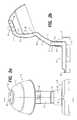
- FIG. 2 bis a right-side, cross-sectional view of the device of FIG. 1 along cross-section line A—A;
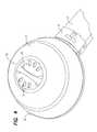
- FIG. 3is a perspective view from the underside of the device of FIG. 1;
- FIG. 4is a perspective, detail view of the top of he device of FIG. 1, illustrating the adjustable vent hereof;
- FIG. 5is a perspective, detail view of the top of he base of the device of FIG. 1;
- FIG. 6is plan, detail view illustrating the interior of the airflow duct in the base of the device of FIG. 1;
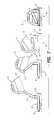
- FIG. 7is a progressive, plan, cross-sectional view along line A—A of the device of FIG. 1, illustrating the transition from fully open to fully closed.
- Device 1comprises a hood 10 , a pivoting arm 12 , a telescoping arm 14 , and a base 16 .
- Hood 10is pivotally coupled to pivoting arm 12 that is, in turn, pivotally supported on telescoping arm 14 .
- Telescoping arm 14is attached to base 16 .
- device 1is constructed of a moldable material, such as a plastic.
- FIG. 2 billustrates that hood 10 is a dome-shaped, generally single-walled receptacle that defines an interior space within which the user's head is placed.
- Hood 10further comprises an exterior semi-spherical shell 11 and a partial inner wall 13 that, together, define a conduit 25 .
- inner wall 13has a plurality of apertures, referred to generally as 26 , that allow air to flow in a shower-like arrangement from conduit 15 into the interior space of hood 10 .
- Vent 20may be opened and closed for the purpose of regulating the flow rate of air from conduit 15 through the apertures 26 . Opening and closing vent 20 is accomplished by hand-turning disc 22 .
- disc 22has a plurality of vent holes, illustrated generally as 24 .
- shell 11has a plurality of holes (not shown) that may be alternately covered and uncovered by disc 22 .
- vents 24are positioned over the holes in shell 11 and, thus, at least some of the airflow within conduit 15 is allowed to escape, instead of travelling through apertures 26 .
- disc 22covers the holes in shell 11 , the fullest volume of air is delivered to the interior hood of 10 .
- the base of hood 10is provided with ledges 32 and 33 .
- Ledge 32engages a sliding latch 18 for the purpose of locking hood 10 into the open position shown in FIG. 1 .
- Ledge 32may also engage a fixed latch 30 located on base 16 for the purpose of securing hood 10 to base 16 (in a manner to be described below).
- ledge 33engages a flexible latch 31 located on base 16 .
- pivoting arm 12is attached to hood 10 at hinge 15 .
- Sliding latch 18which is positioned on pivoting arm 12 , is adapted to releasably engage ledge 32 , whereby hood 10 can be releasably locked into the open position, as illustrated.
- Pivoting arm 12has a generally tubular shape, therein forming a conduit 17 . Conduit 17 is directed into conduit 15 when hood 10 is in the open position.
- Telescoping arm 14which is vertically adjustable, is connected to pivoting arm 12 at hinge 17 .
- fixed arm 14has a generally tubular shape, therein forming a conduit 19 .
- Conduit 19is directed into conduit 17 when hood 10 is in the open position.
- base 16comprises an upwardly directed sleeve 34 integrally connected to a duct 40 .
- Sleeve 34is adapted to receive telescoping arm 14 .
- Duct 40also defines lower air inlets 42 a , 42 b and upper air inlet 48 (see FIG. 5 ).
- duct 40has an elongated central axis and is adapted to contain fans 44 a , 44 b and electric heating element 46 .
- Fans 44 a , 44 bcreate individual airflows, the paths of which overlap to create a combined airflow within duct 40 that passes over heating element 46 and up through sleeve 34 into conduit 19 .
- Fans 44 a and 44 bare staggered or asymmetrical relative to one another along the elongated central axis of duct 40 . Accordingly, fan 44 a is closer to heating element 46 and fan 44 b is farther from heating element 46 . Furthermore, the air flow paths from fans 44 a , 44 b overlap to create a combined airflow.
- the staggered arrangementfurther allows two fans to be fitted within duct 40 , while minimizing the amount of lateral space required. Accordingly, base 16 may also be relatively smaller.
- the staggered arrangementalso minimizes turbulence within the combined airflow created by fans 44 a and 44 b because of the smaller cross section of duct 40 .
- switch 35(see FIG. 5) is moved from the “off” position to either the “Hi” or “Lo” positions and, thereby, fans 44 a and 44 b begin to rotate.
- the rotations of fans 44 a and 44 bcreate a combined airflow that pulls air into duct 40 from both above and below base 16 , through respective air inlets 48 and 42 a , 42 b .
- Fans 44 a , 44 bthen push the combined airflow through heating element 46 .
- the combined airflownext enters sleeve 34 , passes into conduit 19 , through conduits 17 and 15 , and, finally, into the interior of hood 10 through apertures 26 .
- Vent 20may allow a portion of the combined airflow to escape through shell 11 , instead of apertures 26 , depending upon which position the user places vent 20 .
- FIG. 7illustrates that the device of the present invention may be arranged in either an open position or in a closed position.
- flexible latch 31is first pulled away from ledge 33 .
- Hood 10is then tipped back using fixed clasp 30 as a fulcrum. Once ledge 33 clears flexible latch 31 , hood 10 may be pulled slightly away from fixed clasp 30 , thereby releasing ledge 32 .
- pivoting arm 12extends from a nested, substantially horizontal position to a substantially upright position.
- ledge 32is adjacent pivoting arm 12 .
- sliding latch 18may by pushed against knob 32 , thereby holding hood 10 in position relative to pivoting arm 12 .
- base 16counterbalances hood 10 , so that device 1 stays in an upright position. The process is reversed to move device 1 from the open position to the closed position
Landscapes
- Cleaning And Drying Hair (AREA)
Abstract
Description
This Application claims priority from U.S. Provisional Application, Serial No. 60/115,265 filed Jan. 8, 1999.
The present invention relates generally to devices for drying the hair. More particularly, the present invention relates to hair dryers having a hood within which the user's head is placed.
Devices for drying the hair are well known in the art. It is also known in the art to provide hair dryers having hoods or bonnets that serve to direct the heated air used to dry the hair and scalp. The term hood is used herein to describe a rigid, dome-shaped receptacle that has a double-walled construction, wherein the inner wall has one or more air-discharge apertures.
Typically, a hood-type hair dryer includes a motor-driven fan unit for creating an air flow within the hair dryer, a device for heating the airflow (e.g., a heating coil), a hood within which the user's head is positioned, and a conduit directing the heated airflow into the hood.
The amount of time needed to dry a given amount of hair varies as a function of the both the temperature and volume of the air delivered by the hair dryer. The temperature of the air delivered by a hair dryer is limited by the comfort of the user to about 150° F., since experience shows that temperatures above 150° F. cause the hair that dries first to become uncomfortably warm while the user waits for the remaining hair to dry. On the other hand, the temperature of the air should be at least about 100° F. in order to provide an acceptable drying time.
The flow rate of the air delivered by a hair dryer is a parameter that is given considerable attention. Some methods for increasing flow rate are more effective than others. For example, enlarging the air inlet to the fan does not correspondingly increase the flow rate of air delivered by the fan because larger air inlets create more turbulence in the airflow. Moreover, practical constraints, such as size and weight, limit the flow rate of air that a hair dryer can deliver.
Thus, there remains a need for a hair dryer that increases the volume of delivered air, while maintaining comfort and convenience for the user.
Accordingly, it is an object of the present invention to provide a device for drying hair.
It is another object of the present invention to provide a hair drying device that can deliver an increased flow rate of air.
It is still another object of the present invention to provide a hair drying device that can deliver increased air volume and that allows that user to conveniently adjust the volume of air actually delivered.
It is a further object of the present invention to provide a hair drying device that is portable.
A hair dryer incorporating the invention includes a hood, two staggered or asymmetrically placed fans in a base, and an airflow conduit therebetween. The hood of the device may also have an adjustable vent for regulating the amount of air delivered to the head. Moreover, the hood may be secured to the base so as to close the device into a compact form for carrying and storage.
FIG. 1 is a left-side, plan view of a device for drying hair according to the present invention;
FIG. 2ais a rear, plan view of the device of FIG. 1, having cross-section line A—A;
FIG. 2bis a right-side, cross-sectional view of the device of FIG. 1 along cross-section line A—A;
FIG. 3 is a perspective view from the underside of the device of FIG. 1;
FIG. 4 is a perspective, detail view of the top of he device of FIG. 1, illustrating the adjustable vent hereof;
FIG. 5 is a perspective, detail view of the top of he base of the device of FIG. 1;
FIG. 6 is plan, detail view illustrating the interior of the airflow duct in the base of the device of FIG. 1; and
FIG. 7 is a progressive, plan, cross-sectional view along line A—A of the device of FIG. 1, illustrating the transition from fully open to fully closed.
Referring to the drawings, and in particular FIG. 1, there is provided a device for drying hair, according to the present invention, indicated generally as1.Device 1 comprises ahood 10, apivoting arm 12, atelescoping arm 14, and abase 16. Hood10 is pivotally coupled to pivotingarm 12 that is, in turn, pivotally supported on telescopingarm 14.Telescoping arm 14 is attached tobase 16. Preferably,device 1 is constructed of a moldable material, such as a plastic.
FIG. 2billustrates thathood 10 is a dome-shaped, generally single-walled receptacle that defines an interior space within which the user's head is placed. Hood10 further comprises an exteriorsemi-spherical shell 11 and a partialinner wall 13 that, together, define aconduit 25. As illustrated in FIG. 2band FIG. 3,inner wall 13 has a plurality of apertures, referred to generally as26, that allow air to flow in a shower-like arrangement fromconduit 15 into the interior space ofhood 10.
At the apex ofhood 10, there is provided avent 20.Vent 20 may be opened and closed for the purpose of regulating the flow rate of air fromconduit 15 through theapertures 26. Opening and closingvent 20 is accomplished by hand-turningdisc 22. Referring to FIG. 4,disc 22 has a plurality of vent holes, illustrated generally as24. Likewise,shell 11 has a plurality of holes (not shown) that may be alternately covered and uncovered bydisc 22. Whenvent 20 is in the open position,vents 24 are positioned over the holes inshell 11 and, thus, at least some of the airflow withinconduit 15 is allowed to escape, instead of travelling throughapertures 26. By contrast, whendisc 22 covers the holes inshell 11, the fullest volume of air is delivered to the interior hood of10.
Referring again to FIG. 1, the base ofhood 10 is provided with ledges32 and33. Ledge32 engages a slidinglatch 18 for the purpose oflocking hood 10 into the open position shown in FIG.1.Ledge 32 may also engage a fixedlatch 30 located onbase 16 for the purpose of securinghood 10 to base16 (in a manner to be described below). Likewise, whenhood 10 is secured tobase 16, ledge33 engages aflexible latch 31 located onbase 16.
Referring again to FIG. 2b,pivoting arm 12 is attached tohood 10 athinge 15. Slidinglatch 18, which is positioned on pivotingarm 12, is adapted to releasably engageledge 32, wherebyhood 10 can be releasably locked into the open position, as illustrated. Pivotingarm 12 has a generally tubular shape, therein forming aconduit 17.Conduit 17 is directed intoconduit 15 whenhood 10 is in the open position.
As illustrated in FIG. 3,base 16 comprises an upwardly directedsleeve 34 integrally connected to aduct 40.Sleeve 34 is adapted to receivetelescoping arm 14.Duct 40 also defineslower air inlets
Referring to FIG. 6,duct 40 has an elongated central axis and is adapted to containfans electric heating element 46.Fans duct 40 that passes overheating element 46 and up throughsleeve 34 into conduit19.
In operation, switch35 (see FIG. 5) is moved from the “off” position to either the “Hi” or “Lo” positions and, thereby,fans fans duct 40 from both above and belowbase 16, throughrespective air inlets Fans heating element 46. The combined airflow next enterssleeve 34, passes into conduit19, throughconduits hood 10 throughapertures 26.Vent 20 may allow a portion of the combined airflow to escape throughshell 11, instead ofapertures 26, depending upon which position the user places vent20.
FIG. 7 illustrates that the device of the present invention may be arranged in either an open position or in a closed position. To movedevice 1 from the closed position into the open position,flexible latch 31 is first pulled away fromledge 33.Hood 10 is then tipped back using fixedclasp 30 as a fulcrum. Onceledge 33 clearsflexible latch 31,hood 10 may be pulled slightly away from fixedclasp 30, thereby releasingledge 32. By continuing to pullhood 10 away from fixedclasp 30, pivotingarm 12 extends from a nested, substantially horizontal position to a substantially upright position. At this time,ledge 32 is adjacent pivotingarm 12. Thus, slidinglatch 18 may by pushed againstknob 32, thereby holdinghood 10 in position relative to pivotingarm 12. In the open position,base 16counterbalances hood 10, so thatdevice 1 stays in an upright position. The process is reversed to movedevice 1 from the open position to the closed position
The present invention having been described with particular reference to the preferred forms thereof, it will be obvious that various changes and modifications may be made herein without departing from the spirit and scope of the invention as defined in the appended claims.
Claims (18)
1. A device for drying hair comprising:
a hood defining an interior space, said hood having a plurality of apertures directed into said interior space;
a duct elongated along its central axis;
an airflow conduit between said duct and said apertures; and
a plurality of fans, said fans being asymmetrically disposed within said duct along said central axis, each fan having a rotational axis and adapted to produce an individual airflow within said duct such that individual airflows produced by said fans at least partially overlap to form a combined airflow to said airflow conduit, hood, and apertures.
2. The device of claim1, further comprising means disposed within said duct for heating said combined airflow.
3. The device of claim1, wherein said rotational axes are arranged substantially perpendicular to said central axis of said duct.
4. The device of claim1, wherein said hood comprises an inner wall and an outer shell, said apertures set through said inner wall, and said outer shell including means for adjustably venting at least a portion of said combined airflow away from said apertures.
5. The device of claim4, wherein said means for adjustably venting comprises at least one hole set in said outer shell, said hole adjustably covered by movable obstruction means for regulating air flow through said hole.
6. The device of claim1, further comprising means for latching said hood to said base.
7. The device of claim6, wherein said means for latching comprises a flexible latch disposed on said base, a fixed latch disposed on said base, a first ledge disposed on said hood, and a second ledge disposed on said hood, said fixed latch adapted to releasably receive said first ledge and said flexible latch adapted to releasable receive said second ledge.
8. The device of claim7, wherein said hood and said base are both hingedly connected to said airflow conduit, and wherein said airflow conduit nests within said interior space when said hood is latched to said base.
9. The device of claim1, wherein said hood comprises an inner channel having a wall and an outer shell, said apertures set through said wall of said inner channel, and said outer shell including an adjustable vent means that communicates with said inner channel.
10. A device for drying hair comprising:
a hood defining an interior space, said hood having a plurality of apertures directing an airflow into said interior space; and
adjustable vent means positioned in said hood for adjustably venting said airflow away from said apertures.
11. The device of claim10, wherein said hood comprises an inner channel having a wall and an outer shell, said apertures set through said wall of said inner channel, and said outer shell including said adjustable vent means that communicates with said inner channel.
12. The device of claim11, wherein said adjustable vent means comprises at least one hole set through said outer shell, and an adjustable cover for selectively covering or uncovering said at least one hole to regulate airflow therethrough.
13. The device of claim10, further comprising:
a duct elongated along its central axis;
an airflow conduit between said duct and said apertures; and
a plurality of fans, said fans being asymmetrically disposed within said duct along said central axis, each fan having a rotational axis, and each fan adapted to produce an individual airflow within said duct, wherein said individual airflows at least partially overlap to form a combined airflow to said airflow conduit, hood, and apertures.
14. The device of claim13, further comprising means disposed within said duct for heating said combined airflow.
15. The device of claim13, wherein said rotational axes are arranged substantially perpendicular to said central axis of said duct.
16. The device of claim10, further comprising a means for latching said hood to said base.
17. The device of claim16, wherein said means for latching comprises a flexible latch disposed on said base, a fixed latch disposed on said base, a first ledge disposed on said hood, and a second ledge disposed on said hood, said fixed latch adapted to releasably receive said first ledge and said flexible latch adapted to releasable receive said second ledge.
18. The device of claim16, wherein said hood and said base are hingedly connected to said airflow conduit, and wherein said airflow conduit nests within said interior space when said hood is latched to said base.
Priority Applications (1)
| Application Number | Priority Date | Filing Date | Title |
|---|---|---|---|
| US09/480,713US6269549B1 (en) | 1999-01-08 | 2000-01-07 | Device for drying hair |
Applications Claiming Priority (2)
| Application Number | Priority Date | Filing Date | Title |
|---|---|---|---|
| US11526599P | 1999-01-08 | 1999-01-08 | |
| US09/480,713US6269549B1 (en) | 1999-01-08 | 2000-01-07 | Device for drying hair |
Publications (1)
| Publication Number | Publication Date |
|---|---|
| US6269549B1true US6269549B1 (en) | 2001-08-07 |
Family
ID=26813015
Family Applications (1)
| Application Number | Title | Priority Date | Filing Date |
|---|---|---|---|
| US09/480,713Expired - LifetimeUS6269549B1 (en) | 1999-01-08 | 2000-01-07 | Device for drying hair |
Country Status (1)
| Country | Link |
|---|---|
| US (1) | US6269549B1 (en) |
Cited By (82)
| Publication number | Priority date | Publication date | Assignee | Title |
|---|---|---|---|---|
| GB2412314A (en)* | 2004-03-22 | 2005-09-28 | Conair | Collapsible helmet hair dryer |
| US20070119069A1 (en)* | 2005-11-30 | 2007-05-31 | Youngtack Shim | Electromagnetically-shielded hair drying systems and methods |
| US20090060711A1 (en)* | 2007-09-04 | 2009-03-05 | Dyson Technology Limited | Fan |
| US20100150699A1 (en)* | 2008-12-11 | 2010-06-17 | Dyson Technology Limited | Fan |
| GB2468316A (en)* | 2009-03-04 | 2010-09-08 | Dyson Technology Ltd | Telescopic pedestal fan |
| US20100226750A1 (en)* | 2009-03-04 | 2010-09-09 | Dyson Technology Limited | Fan assembly |
| US20100226797A1 (en)* | 2009-03-04 | 2010-09-09 | Dyson Technology Limited | Fan assembly |
| US20100226801A1 (en)* | 2009-03-04 | 2010-09-09 | Dyson Technology Limited | Fan assembly |
| US20100226771A1 (en)* | 2009-03-04 | 2010-09-09 | Dyson Technology Limited | Fan assembly |
| US20100254800A1 (en)* | 2008-09-23 | 2010-10-07 | Dyson Technology Limited | Fan |
| US20110073786A1 (en)* | 2006-08-28 | 2011-03-31 | Youngtack Shim | Generic electromagnetically-countered systems |
| US20110095935A1 (en)* | 2006-08-28 | 2011-04-28 | Youngtack Shim | Electromagnetically-countered systems and methods by maxwell equations |
| US8356804B2 (en) | 2009-03-04 | 2013-01-22 | Dyson Technology Limited | Humidifying apparatus |
| US8366403B2 (en) | 2010-08-06 | 2013-02-05 | Dyson Technology Limited | Fan assembly |
| US8403640B2 (en) | 2009-03-04 | 2013-03-26 | Dyson Technology Limited | Fan assembly |
| US8408869B2 (en) | 2009-03-04 | 2013-04-02 | Dyson Technology Limited | Fan assembly |
| US8430624B2 (en) | 2009-03-04 | 2013-04-30 | Dyson Technology Limited | Fan assembly |
| US8454322B2 (en) | 2009-11-06 | 2013-06-04 | Dyson Technology Limited | Fan having a magnetically attached remote control |
| US8469658B2 (en) | 2009-03-04 | 2013-06-25 | Dyson Technology Limited | Fan |
| US8469660B2 (en) | 2009-03-04 | 2013-06-25 | Dyson Technology Limited | Fan assembly |
| US8475510B2 (en) | 2008-09-23 | 2013-07-02 | Larada Sciences, Inc. | Airflow applicators and related treatment methods |
| US8613601B2 (en) | 2009-03-04 | 2013-12-24 | Dyson Technology Limited | Fan assembly |
| US8625306B2 (en) | 2006-08-28 | 2014-01-07 | Youngtack Shim | Electromagnetically-countered display systems and methods |
| US8721286B2 (en) | 2009-03-04 | 2014-05-13 | Dyson Technology Limited | Fan assembly |
| US8734094B2 (en) | 2010-08-06 | 2014-05-27 | Dyson Technology Limited | Fan assembly |
| US8770946B2 (en) | 2010-03-23 | 2014-07-08 | Dyson Technology Limited | Accessory for a fan |
| US8873940B2 (en) | 2010-08-06 | 2014-10-28 | Dyson Technology Limited | Fan assembly |
| US8882451B2 (en) | 2010-03-23 | 2014-11-11 | Dyson Technology Limited | Fan |
| US8894354B2 (en) | 2010-09-07 | 2014-11-25 | Dyson Technology Limited | Fan |
| US8967979B2 (en) | 2010-10-18 | 2015-03-03 | Dyson Technology Limited | Fan assembly |
| US8967980B2 (en) | 2010-10-18 | 2015-03-03 | Dyson Technology Limited | Fan assembly |
| US9011116B2 (en) | 2010-05-27 | 2015-04-21 | Dyson Technology Limited | Device for blowing air by means of a nozzle assembly |
| USD728092S1 (en) | 2013-08-01 | 2015-04-28 | Dyson Technology Limited | Fan |
| USD728769S1 (en) | 2013-08-01 | 2015-05-05 | Dyson Technology Limited | Fan |
| USD728770S1 (en) | 2013-08-01 | 2015-05-05 | Dyson Technology Limited | Fan |
| USD729373S1 (en) | 2013-03-07 | 2015-05-12 | Dyson Technology Limited | Fan |
| USD729375S1 (en) | 2013-03-07 | 2015-05-12 | Dyson Technology Limited | Fan |
| USD729372S1 (en) | 2013-03-07 | 2015-05-12 | Dyson Technology Limited | Fan |
| USD729374S1 (en) | 2013-03-07 | 2015-05-12 | Dyson Technology Limited | Fan |
| USD729376S1 (en) | 2013-03-07 | 2015-05-12 | Dyson Technology Limited | Fan |
| USD729925S1 (en) | 2013-03-07 | 2015-05-19 | Dyson Technology Limited | Fan |
| US9112395B2 (en) | 2006-08-28 | 2015-08-18 | Youngtack Shim | Electromagnetically-countered actuator systems and methods |
| US9127855B2 (en) | 2011-07-27 | 2015-09-08 | Dyson Technology Limited | Fan assembly |
| US9127689B2 (en) | 2009-03-04 | 2015-09-08 | Dyson Technology Limited | Fan assembly |
| US9151299B2 (en) | 2012-02-06 | 2015-10-06 | Dyson Technology Limited | Fan |
| USD746425S1 (en) | 2013-01-18 | 2015-12-29 | Dyson Technology Limited | Humidifier |
| USD746966S1 (en) | 2013-01-18 | 2016-01-05 | Dyson Technology Limited | Humidifier |
| USD747450S1 (en) | 2013-01-18 | 2016-01-12 | Dyson Technology Limited | Humidifier |
| US9249809B2 (en) | 2012-02-06 | 2016-02-02 | Dyson Technology Limited | Fan |
| USD749231S1 (en) | 2013-01-18 | 2016-02-09 | Dyson Technology Limited | Humidifier |
| US9283573B2 (en) | 2012-02-06 | 2016-03-15 | Dyson Technology Limited | Fan assembly |
| US9328739B2 (en) | 2012-01-19 | 2016-05-03 | Dyson Technology Limited | Fan |
| US9366449B2 (en) | 2012-03-06 | 2016-06-14 | Dyson Technology Limited | Humidifying apparatus |
| US20160206073A1 (en)* | 2015-01-16 | 2016-07-21 | Elchim S.P.A. | Electric hairdryer with a motor protecting device |
| US9410711B2 (en) | 2013-09-26 | 2016-08-09 | Dyson Technology Limited | Fan assembly |
| US9458853B2 (en) | 2011-07-27 | 2016-10-04 | Dyson Technology Limited | Fan assembly |
| US9513028B2 (en) | 2009-03-04 | 2016-12-06 | Dyson Technology Limited | Fan assembly |
| US9568006B2 (en) | 2012-05-16 | 2017-02-14 | Dyson Technology Limited | Fan |
| US9568021B2 (en) | 2012-05-16 | 2017-02-14 | Dyson Technology Limited | Fan |
| US9599356B2 (en) | 2014-07-29 | 2017-03-21 | Dyson Technology Limited | Humidifying apparatus |
| US9732763B2 (en) | 2012-07-11 | 2017-08-15 | Dyson Technology Limited | Fan assembly |
| US9745981B2 (en) | 2011-11-11 | 2017-08-29 | Dyson Technology Limited | Fan assembly |
| US9745996B2 (en) | 2010-12-02 | 2017-08-29 | Dyson Technology Limited | Fan |
| US9752789B2 (en) | 2012-03-06 | 2017-09-05 | Dyson Technology Limited | Humidifying apparatus |
| US9797613B2 (en) | 2012-03-06 | 2017-10-24 | Dyson Technology Limited | Humidifying apparatus |
| US9797414B2 (en) | 2013-07-09 | 2017-10-24 | Dyson Technology Limited | Fan assembly |
| US9797612B2 (en) | 2013-01-29 | 2017-10-24 | Dyson Technology Limited | Fan assembly |
| US9816531B2 (en) | 2008-10-25 | 2017-11-14 | Dyson Technology Limited | Fan utilizing coanda surface |
| US9822778B2 (en) | 2012-04-19 | 2017-11-21 | Dyson Technology Limited | Fan assembly |
| US9903602B2 (en) | 2014-07-29 | 2018-02-27 | Dyson Technology Limited | Humidifying apparatus |
| US9926804B2 (en) | 2010-11-02 | 2018-03-27 | Dyson Technology Limited | Fan assembly |
| US9927136B2 (en) | 2012-03-06 | 2018-03-27 | Dyson Technology Limited | Fan assembly |
| US9982677B2 (en) | 2014-07-29 | 2018-05-29 | Dyson Technology Limited | Fan assembly |
| US10094392B2 (en) | 2011-11-24 | 2018-10-09 | Dyson Technology Limited | Fan assembly |
| US10100836B2 (en) | 2010-10-13 | 2018-10-16 | Dyson Technology Limited | Fan assembly |
| US10145583B2 (en) | 2012-04-04 | 2018-12-04 | Dyson Technology Limited | Heating apparatus |
| US10408478B2 (en) | 2012-03-06 | 2019-09-10 | Dyson Technology Limited | Humidifying apparatus |
| US10428837B2 (en) | 2012-05-16 | 2019-10-01 | Dyson Technology Limited | Fan |
| US10465928B2 (en) | 2012-03-06 | 2019-11-05 | Dyson Technology Limited | Humidifying apparatus |
| US10612565B2 (en) | 2013-01-29 | 2020-04-07 | Dyson Technology Limited | Fan assembly |
| US11213174B2 (en)* | 2018-09-19 | 2022-01-04 | Lg Electronics Inc. | Dryer |
| CN116744818A (en)* | 2020-12-23 | 2023-09-12 | 戴森技术有限公司 | Hair care appliance |
Citations (11)
| Publication number | Priority date | Publication date | Assignee | Title |
|---|---|---|---|---|
| US3594916A (en) | 1969-08-08 | 1971-07-27 | Arthur W Mason | Hair dryers |
| US3645007A (en) | 1970-01-14 | 1972-02-29 | Sunbeam Corp | Hair dryer and facial sauna |
| US3724092A (en) | 1971-07-12 | 1973-04-03 | Westinghouse Electric Corp | Portable hair dryer |
| US3868495A (en) | 1972-12-02 | 1975-02-25 | Firth Cleveland Ltd | Electric hair drying device |
| US3981314A (en) | 1975-09-25 | 1976-09-21 | Venus Electric Limited | Hair dryer |
| US4021930A (en) | 1976-01-13 | 1977-05-10 | Sunbeam Corporation | Hair dryer |
| US4038759A (en) | 1972-11-17 | 1977-08-02 | Firth Cleveland Limited | Hairdryer |
| US4118874A (en) | 1975-04-17 | 1978-10-10 | L'oreal | Hair dryer, especially for long hair |
| US4413428A (en)* | 1977-01-21 | 1983-11-08 | Indola Cosmetics B.V. | Hair dryer casing |
| US4486961A (en)* | 1982-04-10 | 1984-12-11 | GAP Gesellschaft f/u/ r Auswertungen und Patente AG | Hair dryer |
| US4744154A (en)* | 1984-09-11 | 1988-05-17 | Wella Aktiengesellschaft | Measuring and controlling the moisture content of hair |
- 2000
- 2000-01-07USUS09/480,713patent/US6269549B1/ennot_activeExpired - Lifetime
Patent Citations (11)
| Publication number | Priority date | Publication date | Assignee | Title |
|---|---|---|---|---|
| US3594916A (en) | 1969-08-08 | 1971-07-27 | Arthur W Mason | Hair dryers |
| US3645007A (en) | 1970-01-14 | 1972-02-29 | Sunbeam Corp | Hair dryer and facial sauna |
| US3724092A (en) | 1971-07-12 | 1973-04-03 | Westinghouse Electric Corp | Portable hair dryer |
| US4038759A (en) | 1972-11-17 | 1977-08-02 | Firth Cleveland Limited | Hairdryer |
| US3868495A (en) | 1972-12-02 | 1975-02-25 | Firth Cleveland Ltd | Electric hair drying device |
| US4118874A (en) | 1975-04-17 | 1978-10-10 | L'oreal | Hair dryer, especially for long hair |
| US3981314A (en) | 1975-09-25 | 1976-09-21 | Venus Electric Limited | Hair dryer |
| US4021930A (en) | 1976-01-13 | 1977-05-10 | Sunbeam Corporation | Hair dryer |
| US4413428A (en)* | 1977-01-21 | 1983-11-08 | Indola Cosmetics B.V. | Hair dryer casing |
| US4486961A (en)* | 1982-04-10 | 1984-12-11 | GAP Gesellschaft f/u/ r Auswertungen und Patente AG | Hair dryer |
| US4744154A (en)* | 1984-09-11 | 1988-05-17 | Wella Aktiengesellschaft | Measuring and controlling the moisture content of hair |
Cited By (128)
| Publication number | Priority date | Publication date | Assignee | Title |
|---|---|---|---|---|
| GB2412314A (en)* | 2004-03-22 | 2005-09-28 | Conair | Collapsible helmet hair dryer |
| US20070119069A1 (en)* | 2005-11-30 | 2007-05-31 | Youngtack Shim | Electromagnetically-shielded hair drying systems and methods |
| US8929846B2 (en) | 2006-08-28 | 2015-01-06 | Youngtack Shim | Generic electromagnetically-countered methods |
| US8625306B2 (en) | 2006-08-28 | 2014-01-07 | Youngtack Shim | Electromagnetically-countered display systems and methods |
| US8369105B2 (en) | 2006-08-28 | 2013-02-05 | Youngtack Shim | Generic electromagnetically-countered systems |
| US9112395B2 (en) | 2006-08-28 | 2015-08-18 | Youngtack Shim | Electromagnetically-countered actuator systems and methods |
| US8588436B2 (en) | 2006-08-28 | 2013-11-19 | Youngtack Shim | Generic electromagnetically-countered methods |
| US9566429B2 (en) | 2006-08-28 | 2017-02-14 | Youngtack Shim | Electromagnetically-countered display systems and methods |
| US9319085B2 (en) | 2006-08-28 | 2016-04-19 | Youngtack Shim | Generic electromagnetically-countered methods |
| US9114254B2 (en) | 2006-08-28 | 2015-08-25 | Youngtack Shim | Electromagnetically-countered display systems and methods |
| US8588437B2 (en) | 2006-08-28 | 2013-11-19 | Youngtack Shim | Generic electromagnetically-countering processes |
| US20110073786A1 (en)* | 2006-08-28 | 2011-03-31 | Youngtack Shim | Generic electromagnetically-countered systems |
| US20110095935A1 (en)* | 2006-08-28 | 2011-04-28 | Youngtack Shim | Electromagnetically-countered systems and methods by maxwell equations |
| US20090060711A1 (en)* | 2007-09-04 | 2009-03-05 | Dyson Technology Limited | Fan |
| US8308445B2 (en) | 2007-09-04 | 2012-11-13 | Dyson Technology Limited | Fan |
| US9249810B2 (en) | 2007-09-04 | 2016-02-02 | Dyson Technology Limited | Fan |
| US8403650B2 (en) | 2007-09-04 | 2013-03-26 | Dyson Technology Limited | Fan |
| US20090060710A1 (en)* | 2007-09-04 | 2009-03-05 | Dyson Technology Limited | Fan |
| US8764412B2 (en) | 2007-09-04 | 2014-07-01 | Dyson Technology Limited | Fan |
| US20100254800A1 (en)* | 2008-09-23 | 2010-10-07 | Dyson Technology Limited | Fan |
| US7931449B2 (en) | 2008-09-23 | 2011-04-26 | Dyson Technology Limited | Fan |
| US8348629B2 (en) | 2008-09-23 | 2013-01-08 | Dyston Technology Limited | Fan |
| US8475510B2 (en) | 2008-09-23 | 2013-07-02 | Larada Sciences, Inc. | Airflow applicators and related treatment methods |
| US9816531B2 (en) | 2008-10-25 | 2017-11-14 | Dyson Technology Limited | Fan utilizing coanda surface |
| US10145388B2 (en) | 2008-10-25 | 2018-12-04 | Dyson Technology Limited | Fan with a filter |
| US8092166B2 (en) | 2008-12-11 | 2012-01-10 | Dyson Technology Limited | Fan |
| US20100150699A1 (en)* | 2008-12-11 | 2010-06-17 | Dyson Technology Limited | Fan |
| US8784071B2 (en) | 2009-03-04 | 2014-07-22 | Dyson Technology Limited | Fan assembly |
| US9599368B2 (en) | 2009-03-04 | 2017-03-21 | Dyson Technology Limited | Nozzle for bladeless fan assembly with heater |
| US10006657B2 (en) | 2009-03-04 | 2018-06-26 | Dyson Technology Limited | Fan assembly |
| US8408869B2 (en) | 2009-03-04 | 2013-04-02 | Dyson Technology Limited | Fan assembly |
| US8430624B2 (en) | 2009-03-04 | 2013-04-30 | Dyson Technology Limited | Fan assembly |
| US8403640B2 (en) | 2009-03-04 | 2013-03-26 | Dyson Technology Limited | Fan assembly |
| US8469658B2 (en) | 2009-03-04 | 2013-06-25 | Dyson Technology Limited | Fan |
| US8469655B2 (en) | 2009-03-04 | 2013-06-25 | Dyson Technology Limited | Fan assembly |
| US8469660B2 (en) | 2009-03-04 | 2013-06-25 | Dyson Technology Limited | Fan assembly |
| US8356804B2 (en) | 2009-03-04 | 2013-01-22 | Dyson Technology Limited | Humidifying apparatus |
| US8529203B2 (en) | 2009-03-04 | 2013-09-10 | Dyson Technology Limited | Fan assembly |
| US8348596B2 (en) | 2009-03-04 | 2013-01-08 | Dyson Technology Limited | Fan assembly |
| US8348597B2 (en) | 2009-03-04 | 2013-01-08 | Dyson Technology Limited | Fan assembly |
| US8613601B2 (en) | 2009-03-04 | 2013-12-24 | Dyson Technology Limited | Fan assembly |
| US8308432B2 (en) | 2009-03-04 | 2012-11-13 | Dyson Technology Limited | Fan assembly |
| US8684687B2 (en) | 2009-03-04 | 2014-04-01 | Dyson Technology Limited | Fan assembly |
| US8708650B2 (en) | 2009-03-04 | 2014-04-29 | Dyson Technology Limited | Fan assembly |
| US8714937B2 (en) | 2009-03-04 | 2014-05-06 | Dyson Technology Limited | Fan assembly |
| US8721286B2 (en) | 2009-03-04 | 2014-05-13 | Dyson Technology Limited | Fan assembly |
| US20100226801A1 (en)* | 2009-03-04 | 2010-09-09 | Dyson Technology Limited | Fan assembly |
| US8246317B2 (en) | 2009-03-04 | 2012-08-21 | Dyson Technology Limited | Fan assembly |
| GB2468316B (en)* | 2009-03-04 | 2015-09-16 | Dyson Technology Ltd | Telescopic pedestal fan assembly |
| US8783663B2 (en) | 2009-03-04 | 2014-07-22 | Dyson Technology Limited | Humidifying apparatus |
| US9127689B2 (en) | 2009-03-04 | 2015-09-08 | Dyson Technology Limited | Fan assembly |
| US8784049B2 (en) | 2009-03-04 | 2014-07-22 | Dyson Technology Limited | Fan |
| US7972111B2 (en) | 2009-03-04 | 2011-07-05 | Dyson Technology Limited | Fan assembly |
| US20110223014A1 (en)* | 2009-03-04 | 2011-09-15 | Dyson Technology Limited | Fan assembly |
| US8052379B2 (en) | 2009-03-04 | 2011-11-08 | Dyson Technology Limited | Fan assembly |
| US8197226B2 (en) | 2009-03-04 | 2012-06-12 | Dyson Technology Limited | Fan assembly |
| US8932028B2 (en) | 2009-03-04 | 2015-01-13 | Dyson Technology Limited | Fan assembly |
| US9513028B2 (en) | 2009-03-04 | 2016-12-06 | Dyson Technology Limited | Fan assembly |
| US10221860B2 (en) | 2009-03-04 | 2019-03-05 | Dyson Technology Limited | Fan assembly |
| US20100226797A1 (en)* | 2009-03-04 | 2010-09-09 | Dyson Technology Limited | Fan assembly |
| US20100226771A1 (en)* | 2009-03-04 | 2010-09-09 | Dyson Technology Limited | Fan assembly |
| US20100226750A1 (en)* | 2009-03-04 | 2010-09-09 | Dyson Technology Limited | Fan assembly |
| GB2468316A (en)* | 2009-03-04 | 2010-09-08 | Dyson Technology Ltd | Telescopic pedestal fan |
| US8454322B2 (en) | 2009-11-06 | 2013-06-04 | Dyson Technology Limited | Fan having a magnetically attached remote control |
| US9004878B2 (en) | 2009-11-06 | 2015-04-14 | Dyson Technology Limited | Fan having a magnetically attached remote control |
| US8882451B2 (en) | 2010-03-23 | 2014-11-11 | Dyson Technology Limited | Fan |
| US8770946B2 (en) | 2010-03-23 | 2014-07-08 | Dyson Technology Limited | Accessory for a fan |
| US9011116B2 (en) | 2010-05-27 | 2015-04-21 | Dyson Technology Limited | Device for blowing air by means of a nozzle assembly |
| US8734094B2 (en) | 2010-08-06 | 2014-05-27 | Dyson Technology Limited | Fan assembly |
| US8873940B2 (en) | 2010-08-06 | 2014-10-28 | Dyson Technology Limited | Fan assembly |
| US10344773B2 (en) | 2010-08-06 | 2019-07-09 | Dyson Technology Limited | Fan assembly |
| US8366403B2 (en) | 2010-08-06 | 2013-02-05 | Dyson Technology Limited | Fan assembly |
| US8894354B2 (en) | 2010-09-07 | 2014-11-25 | Dyson Technology Limited | Fan |
| US9745988B2 (en) | 2010-09-07 | 2017-08-29 | Dyson Technology Limited | Fan |
| US10100836B2 (en) | 2010-10-13 | 2018-10-16 | Dyson Technology Limited | Fan assembly |
| US8967979B2 (en) | 2010-10-18 | 2015-03-03 | Dyson Technology Limited | Fan assembly |
| US8967980B2 (en) | 2010-10-18 | 2015-03-03 | Dyson Technology Limited | Fan assembly |
| US9926804B2 (en) | 2010-11-02 | 2018-03-27 | Dyson Technology Limited | Fan assembly |
| US9745996B2 (en) | 2010-12-02 | 2017-08-29 | Dyson Technology Limited | Fan |
| US9291361B2 (en) | 2011-07-27 | 2016-03-22 | Dyson Technology Limited | Fan assembly |
| US9335064B2 (en) | 2011-07-27 | 2016-05-10 | Dyson Technology Limited | Fan assembly |
| US10094581B2 (en) | 2011-07-27 | 2018-10-09 | Dyson Technology Limited | Fan assembly |
| US9458853B2 (en) | 2011-07-27 | 2016-10-04 | Dyson Technology Limited | Fan assembly |
| US9127855B2 (en) | 2011-07-27 | 2015-09-08 | Dyson Technology Limited | Fan assembly |
| US9745981B2 (en) | 2011-11-11 | 2017-08-29 | Dyson Technology Limited | Fan assembly |
| US10094392B2 (en) | 2011-11-24 | 2018-10-09 | Dyson Technology Limited | Fan assembly |
| US9328739B2 (en) | 2012-01-19 | 2016-05-03 | Dyson Technology Limited | Fan |
| US9249809B2 (en) | 2012-02-06 | 2016-02-02 | Dyson Technology Limited | Fan |
| US9151299B2 (en) | 2012-02-06 | 2015-10-06 | Dyson Technology Limited | Fan |
| US9283573B2 (en) | 2012-02-06 | 2016-03-15 | Dyson Technology Limited | Fan assembly |
| US10465928B2 (en) | 2012-03-06 | 2019-11-05 | Dyson Technology Limited | Humidifying apparatus |
| US9927136B2 (en) | 2012-03-06 | 2018-03-27 | Dyson Technology Limited | Fan assembly |
| US9366449B2 (en) | 2012-03-06 | 2016-06-14 | Dyson Technology Limited | Humidifying apparatus |
| US9752789B2 (en) | 2012-03-06 | 2017-09-05 | Dyson Technology Limited | Humidifying apparatus |
| US9797613B2 (en) | 2012-03-06 | 2017-10-24 | Dyson Technology Limited | Humidifying apparatus |
| US10563875B2 (en) | 2012-03-06 | 2020-02-18 | Dyson Technology Limited | Humidifying apparatus |
| US10408478B2 (en) | 2012-03-06 | 2019-09-10 | Dyson Technology Limited | Humidifying apparatus |
| US10145583B2 (en) | 2012-04-04 | 2018-12-04 | Dyson Technology Limited | Heating apparatus |
| US9822778B2 (en) | 2012-04-19 | 2017-11-21 | Dyson Technology Limited | Fan assembly |
| US10428837B2 (en) | 2012-05-16 | 2019-10-01 | Dyson Technology Limited | Fan |
| US9568021B2 (en) | 2012-05-16 | 2017-02-14 | Dyson Technology Limited | Fan |
| US10309420B2 (en) | 2012-05-16 | 2019-06-04 | Dyson Technology Limited | Fan |
| US9568006B2 (en) | 2012-05-16 | 2017-02-14 | Dyson Technology Limited | Fan |
| US9732763B2 (en) | 2012-07-11 | 2017-08-15 | Dyson Technology Limited | Fan assembly |
| USD749231S1 (en) | 2013-01-18 | 2016-02-09 | Dyson Technology Limited | Humidifier |
| USD746425S1 (en) | 2013-01-18 | 2015-12-29 | Dyson Technology Limited | Humidifier |
| USD746966S1 (en) | 2013-01-18 | 2016-01-05 | Dyson Technology Limited | Humidifier |
| USD747450S1 (en) | 2013-01-18 | 2016-01-12 | Dyson Technology Limited | Humidifier |
| US9797612B2 (en) | 2013-01-29 | 2017-10-24 | Dyson Technology Limited | Fan assembly |
| US10612565B2 (en) | 2013-01-29 | 2020-04-07 | Dyson Technology Limited | Fan assembly |
| USD729372S1 (en) | 2013-03-07 | 2015-05-12 | Dyson Technology Limited | Fan |
| USD729374S1 (en) | 2013-03-07 | 2015-05-12 | Dyson Technology Limited | Fan |
| USD729376S1 (en) | 2013-03-07 | 2015-05-12 | Dyson Technology Limited | Fan |
| USD729375S1 (en) | 2013-03-07 | 2015-05-12 | Dyson Technology Limited | Fan |
| USD729373S1 (en) | 2013-03-07 | 2015-05-12 | Dyson Technology Limited | Fan |
| USD729925S1 (en) | 2013-03-07 | 2015-05-19 | Dyson Technology Limited | Fan |
| US9797414B2 (en) | 2013-07-09 | 2017-10-24 | Dyson Technology Limited | Fan assembly |
| USD728770S1 (en) | 2013-08-01 | 2015-05-05 | Dyson Technology Limited | Fan |
| USD728769S1 (en) | 2013-08-01 | 2015-05-05 | Dyson Technology Limited | Fan |
| USD728092S1 (en) | 2013-08-01 | 2015-04-28 | Dyson Technology Limited | Fan |
| US9410711B2 (en) | 2013-09-26 | 2016-08-09 | Dyson Technology Limited | Fan assembly |
| US9982677B2 (en) | 2014-07-29 | 2018-05-29 | Dyson Technology Limited | Fan assembly |
| US9903602B2 (en) | 2014-07-29 | 2018-02-27 | Dyson Technology Limited | Humidifying apparatus |
| US9599356B2 (en) | 2014-07-29 | 2017-03-21 | Dyson Technology Limited | Humidifying apparatus |
| US20160206073A1 (en)* | 2015-01-16 | 2016-07-21 | Elchim S.P.A. | Electric hairdryer with a motor protecting device |
| US9737125B2 (en)* | 2015-01-16 | 2017-08-22 | Elchim S.P.A. | Electric hairdryer with a motor protecting device |
| US11213174B2 (en)* | 2018-09-19 | 2022-01-04 | Lg Electronics Inc. | Dryer |
| CN116744818A (en)* | 2020-12-23 | 2023-09-12 | 戴森技术有限公司 | Hair care appliance |
Similar Documents
| Publication | Publication Date | Title |
|---|---|---|
| US6269549B1 (en) | Device for drying hair | |
| US4232454A (en) | Variable airflow hair treatment device | |
| US11857052B2 (en) | Water separator for a hair dryer | |
| US11517091B2 (en) | Hair dryer | |
| CN111248594B (en) | Accessories for handheld devices | |
| CN1024999C (en) | Hair drying device | |
| JP2000516483A (en) | Hand-held blow dryer with airflow control means | |
| CN210371240U (en) | Air circulation system | |
| US6058886A (en) | Pet cage dryer | |
| KR20190001102A (en) | Drying device for pet | |
| CN102639024A (en) | Accessories for hair treatment equipment | |
| KR101616062B1 (en) | Hair drier for long hair | |
| EP0931534A1 (en) | Incubator mattress tray with warming function | |
| US4297564A (en) | Hair dryer | |
| MX2012009086A (en) | Hair drying device with directed air jets obtained by coupling an electric hair drier and a hair drier with directed air jets. | |
| US5235760A (en) | Hair dryer with blower and radiant heating modes of operation | |
| US3775861A (en) | Hair dryer | |
| CN205182414U (en) | Air outlet adjusting device for air purifier | |
| EP0064405A1 (en) | Apparatus for grooming hair | |
| US6301800B1 (en) | Method of use for inverted bonnet hair dryer | |
| US3849902A (en) | Collapsible hair dryer | |
| US4021930A (en) | Hair dryer | |
| JPH046643Y2 (en) | ||
| US6293030B1 (en) | Hair drying apparatus | |
| CN116507241A (en) | Freely customizable hair passage systems, methods, devices and kits |
Legal Events
| Date | Code | Title | Description |
|---|---|---|---|
| AS | Assignment | Owner name:CONAIR CORPORATION, CONNECTICUT Free format text:ASSIGNMENT OF ASSIGNORS INTEREST;ASSIGNORS:CARLUCCI, VITO;TAYLOR, HAROLD R.;DACOSTA, SERGIO;REEL/FRAME:010559/0311 Effective date:20000106 | |
| STCF | Information on status: patent grant | Free format text:PATENTED CASE | |
| FPAY | Fee payment | Year of fee payment:4 | |
| FPAY | Fee payment | Year of fee payment:8 | |
| FPAY | Fee payment | Year of fee payment:12 |