US6269505B1 - Inflatable cushioning device with manifold system - Google Patents
Inflatable cushioning device with manifold systemDownload PDFInfo
- Publication number
- US6269505B1 US6269505B1US09/295,139US29513999AUS6269505B1US 6269505 B1US6269505 B1US 6269505B1US 29513999 AUS29513999 AUS 29513999AUS 6269505 B1US6269505 B1US 6269505B1
- Authority
- US
- United States
- Prior art keywords
- fluid
- support
- pressure
- cushioning device
- envelope
- Prior art date
- Legal status (The legal status is an assumption and is not a legal conclusion. Google has not performed a legal analysis and makes no representation as to the accuracy of the status listed.)
- Expired - Lifetime
Links
- 239000012530fluidSubstances0.000claimsabstractdescription166
- 238000002407reformingMethods0.000claimsdescription19
- 239000012858resilient materialSubstances0.000claimsdescription7
- 230000037396body weightEffects0.000claimsdescription4
- 238000000034methodMethods0.000claimsdescription2
- 230000005540biological transmissionEffects0.000claims1
- 230000006378damageEffects0.000abstractdescription4
- 238000000554physical therapyMethods0.000abstract1
- 238000007790scrapingMethods0.000abstract1
- 210000004027cellAnatomy0.000description130
- 230000000451tissue damageEffects0.000description9
- 231100000827tissue damageToxicity0.000description9
- 208000004210Pressure UlcerDiseases0.000description7
- 239000000463materialSubstances0.000description7
- 230000000284resting effectEffects0.000description7
- 206010011985Decubitus ulcerDiseases0.000description6
- 210000004872soft tissueAnatomy0.000description6
- IJGRMHOSHXDMSA-UHFFFAOYSA-NAtomic nitrogenChemical compoundN#NIJGRMHOSHXDMSA-UHFFFAOYSA-N0.000description4
- 230000015572biosynthetic processEffects0.000description4
- XLYOFNOQVPJJNP-UHFFFAOYSA-NwaterSubstancesOXLYOFNOQVPJJNP-UHFFFAOYSA-N0.000description4
- -1e.g.Substances0.000description3
- 239000006260foamSubstances0.000description3
- 238000012423maintenanceMethods0.000description3
- 238000012986modificationMethods0.000description3
- 230000004048modificationEffects0.000description3
- 230000008439repair processEffects0.000description3
- 210000001519tissueAnatomy0.000description3
- 238000005299abrasionMethods0.000description2
- 230000000845anti-microbial effectEffects0.000description2
- 239000004599antimicrobialSubstances0.000description2
- 230000009286beneficial effectEffects0.000description2
- 230000007423decreaseEffects0.000description2
- 210000003746featherAnatomy0.000description2
- 239000006261foam materialSubstances0.000description2
- 208000014674injuryDiseases0.000description2
- 230000001788irregularEffects0.000description2
- 210000004880lymph fluidAnatomy0.000description2
- 229910052757nitrogenInorganic materials0.000description2
- 208000027418Wounds and injuryDiseases0.000description1
- 230000009471actionEffects0.000description1
- 239000008280bloodSubstances0.000description1
- 210000004369bloodAnatomy0.000description1
- 230000007850degenerationEffects0.000description1
- 238000013461designMethods0.000description1
- 238000006073displacement reactionMethods0.000description1
- 230000000694effectsEffects0.000description1
- 239000004744fabricSubstances0.000description1
- 239000000835fiberSubstances0.000description1
- 230000035876healingEffects0.000description1
- 238000004519manufacturing processMethods0.000description1
- 230000007246mechanismEffects0.000description1
- 230000001105regulatory effectEffects0.000description1
- 230000000630rising effectEffects0.000description1
- 230000001225therapeutic effectEffects0.000description1
- 238000012549trainingMethods0.000description1
- 230000008733traumaEffects0.000description1
Images


Classifications
- A—HUMAN NECESSITIES
- A61—MEDICAL OR VETERINARY SCIENCE; HYGIENE
- A61G—TRANSPORT, PERSONAL CONVEYANCES, OR ACCOMMODATION SPECIALLY ADAPTED FOR PATIENTS OR DISABLED PERSONS; OPERATING TABLES OR CHAIRS; CHAIRS FOR DENTISTRY; FUNERAL DEVICES
- A61G7/00—Beds specially adapted for nursing; Devices for lifting patients or disabled persons
- A61G7/05—Parts, details or accessories of beds
- A61G7/057—Arrangements for preventing bed-sores or for supporting patients with burns, e.g. mattresses specially adapted therefor
- A61G7/05769—Arrangements for preventing bed-sores or for supporting patients with burns, e.g. mattresses specially adapted therefor with inflatable chambers
- A—HUMAN NECESSITIES
- A47—FURNITURE; DOMESTIC ARTICLES OR APPLIANCES; COFFEE MILLS; SPICE MILLS; SUCTION CLEANERS IN GENERAL
- A47C—CHAIRS; SOFAS; BEDS
- A47C27/00—Spring, stuffed or fluid mattresses or cushions specially adapted for chairs, beds or sofas
- A47C27/08—Fluid mattresses
- A47C27/081—Fluid mattresses of pneumatic type
- A47C27/084—Fluid mattresses of pneumatic type self inflating
- A—HUMAN NECESSITIES
- A47—FURNITURE; DOMESTIC ARTICLES OR APPLIANCES; COFFEE MILLS; SPICE MILLS; SUCTION CLEANERS IN GENERAL
- A47C—CHAIRS; SOFAS; BEDS
- A47C27/00—Spring, stuffed or fluid mattresses or cushions specially adapted for chairs, beds or sofas
- A47C27/08—Fluid mattresses
- A47C27/088—Fluid mattresses incorporating elastic bodies, e.g. foam
- A—HUMAN NECESSITIES
- A47—FURNITURE; DOMESTIC ARTICLES OR APPLIANCES; COFFEE MILLS; SPICE MILLS; SUCTION CLEANERS IN GENERAL
- A47C—CHAIRS; SOFAS; BEDS
- A47C27/00—Spring, stuffed or fluid mattresses or cushions specially adapted for chairs, beds or sofas
- A47C27/08—Fluid mattresses
- A47C27/10—Fluid mattresses with two or more independently-fillable chambers
- A—HUMAN NECESSITIES
- A47—FURNITURE; DOMESTIC ARTICLES OR APPLIANCES; COFFEE MILLS; SPICE MILLS; SUCTION CLEANERS IN GENERAL
- A47C—CHAIRS; SOFAS; BEDS
- A47C27/00—Spring, stuffed or fluid mattresses or cushions specially adapted for chairs, beds or sofas
- A47C27/14—Spring, stuffed or fluid mattresses or cushions specially adapted for chairs, beds or sofas with foamed material inlays
- A47C27/18—Spring, stuffed or fluid mattresses or cushions specially adapted for chairs, beds or sofas with foamed material inlays in combination with inflatable bodies
- A—HUMAN NECESSITIES
- A61—MEDICAL OR VETERINARY SCIENCE; HYGIENE
- A61G—TRANSPORT, PERSONAL CONVEYANCES, OR ACCOMMODATION SPECIALLY ADAPTED FOR PATIENTS OR DISABLED PERSONS; OPERATING TABLES OR CHAIRS; CHAIRS FOR DENTISTRY; FUNERAL DEVICES
- A61G7/00—Beds specially adapted for nursing; Devices for lifting patients or disabled persons
- A61G7/05—Parts, details or accessories of beds
- A61G7/057—Arrangements for preventing bed-sores or for supporting patients with burns, e.g. mattresses specially adapted therefor
- A61G7/05715—Arrangements for preventing bed-sores or for supporting patients with burns, e.g. mattresses specially adapted therefor with modular blocks, or inserts, with layers of different material
Definitions
- the present inventionrelates generally to an inflatable cushioning device for body supports such as a mattress, sofa, or chair cushion.
- the present inventionrelates to a body support for preventing the formation of pressure induced soft tissue damage.
- inflatable cushioning devicesfor use with body supports, such as a mattress, sofa, seat, or the like, typically included a plurality of air cells or bladders that are inflated to support a person.
- the air cellsprovide support to the person, and can be inflated to a desired pressure level to provide the person with a predetermined level of comfort and support.
- cushioning devicesincluding a plurality of air cells are often used to provide different levels of support under various portions of a patient's body.
- a mattressmay include separate air cells located in the upper, middle, and lower portions of the mattress. These air cells can be inflated to different pressures to support the upper, middle, and lower portions of the patient's body with different pressures.
- thismay be accomplished by inflating the air cell under the patient's leg so that the heel is lifted from the mattress.
- the continuous heel pressureis relieved and the formation of a bed sore on the heel is prevented.
- Air cushion devicestypically require an external pump to inflate the air cells in the device.
- the air cushion devicesare pre-inflated in the manufacturing plant and are shipped to a field location for use.
- a problemmay develop when the atmospheric pressure at the inflation location is different from the atomospheric pressure at the field location where the device is used. For example, if the field location atmospheric pressure is lower than the atmospheric pressure at the inflation location, the air cells in the field will expand and become firmer.
- the present inventionprovides a cushioning device for a mattress, seat, sofa, or the like where support is obtained from a fluid such as atmospheric air.
- the cushioning devicehas few moving parts, is user controllable, requires minimal maintenance, and is easily repairable.
- the cushioning device of the present inventionincludes a support system apparatus, a sleeve apparatus, a jacket, a topper cushion, and an outer cover.
- the support system apparatusincludes at least one support cell for providing lifting support for a body.
- Each support cellincludes an envelope containing a fluid.
- Application of an external load on an outer surface of the envelopecauses the envelope to deform into a compressed form.
- the envelopeincludes a reforming element that is capable of providing a reforming force to the interior surface of the envelope, to return the envelope to its original unloaded form.
- the reforming elementis preferably made from a resilient foam material, however, other resilient means can be used.
- An intake valve and an exhaust valveare included in each support cell.
- the exhaust valve in each support cellis connected to an exhaust control system.
- the intake valve in each support cellis connected to an intake control system.
- Each intake valveincludes an intake check valve allowing fluid to flow into the support cell, while preventing fluid from flowing out of the support cell.
- Each exhaust valveincludes an exhaust check valve allowing fluid to flow out of the support cell, while preventing fluid from flowing into the support cell.
- the intake control systemis connected to a fluid supply reservoir.
- the exhaust control systemis connected to a fluid exhaust reservoir.
- the fluid included in the supply and exhaust reservoirsis air, however, any suitable fluid, e.g., water or nitrogen, can be used.
- the fluid supply and exhaust reservoirsmay comprise the same reservoir, and may comprise an ambient source of fluid such as atmospheric air.
- the weight of a body of a person, patient, or animal resting on the envelopedeforms the envelope.
- a patientwill be used as an example of body resting on a the envelope.
- the pressure of the fluid within the envelopeincreases as the volume of the envelope decreases under deformation.
- the fluid in the envelopeflows out of the envelope through the exhaust valve and into the exhaust control system.
- the fluidflows from the exhaust control system into the fluid exhaust reservoir.
- the area of the envelope supporting the loadincreases. Equilibrium is achieved when the forces within the envelope, including the pressure of the fluid within the envelope multiplied by the area of the envelope supporting the load, plus the force provided by the reforming element equal the weight of the load.
- a controllable pressure relief valveis included in the exhaust control system so that a maximum pressure level of the fluid within the envelope can be set and maintained. Different selected maximum pressure levels of the fluid allow the support cell to accommodate different weights or allow different degrees of conformation between the patient and the envelope surface. Preferably, the maximum pressure level of the fluid is set to ensure that the interface pressure under the entire contact surface of the patient is below the pressure that may cause soft tissue damage such as pressure sores to occur.
- the reforming elementexerts an outward force on the interior surface of the envelope.
- a partial vacuumis created in the interior space of the envelope, causing fluid to be drawn back into the interior space of the envelope.
- the fluidis drawn from the fluid supply reservoir into the intake control system, through the intake valve, and into the interior space of the envelope.
- the intake valveincludes a one way intake check valve that permits fluid to re-enter the interior space of the envelope, while preventing fluid from exiting the interior space of the envelope.
- the support cells included in the present inventioncan use atmospheric pressure as the pressure source for inflation. Therefore, when the fluid supply and exhaust reservoirs comprise atmospheric air, inflation can be accomplished without the need for expensive blowers, pumps or microprocessors as required by previously available “treatment products.”
- a plurality of support cellscan be interconnected with the intake control system and the exhaust control system to create a support system apparatus.
- the support system apparatuscan support a patient by providing self adjusting pressure management to the entire contact surface of the patient.
- the support system apparatusprovides a low interface pressure under the entire surface of the patient being supported. For example, if the patient is lying on the support system apparatus, the support system apparatus ensures that the interface pressure under the entire contact surface of the patient is below the pressure that may cause soft tissue damage to occur.
- the support system apparatusalso has the ability to self-adjust every time a patient moves, or is repositioned on the support system apparatus.
- the support cells within the support system apparatusautomatically inflate or deflate as necessary, to maintain a low interface pressure under the entire patient.
- Each support zonecomprises at least one support cell.
- Each support cellincludes at least one intake valve and at least one exhaust valve.
- the intake valve for each support cell in each support zoneis connected to the intake control system.
- the exhaust valves from each support cell in a single support zoneare connected to a single exhaust control system.
- Each support zonehas a separate exhaust control system.
- the intake control systemis connected to the fluid supply reservoir.
- the exhaust control system for each support zoneis connected to the fluid exhaust reservoir.
- the pressure level in each support zoneis set at a different level. For example, if the support system apparatus comprises a mattress in a bed, the upper, middle, and lower zones of the support system apparatus can be set to provide a different level of pressure or firmness for the upper, middle, and lower portions of the patient's body.
- the sleeve apparatusincludes a cell cover surrounding each support cell.
- each cell coveris attached to an adjacent cell cover.
- the cell coverallows the surface of the envelope of the support cell to slide freely along a first side of the cell cover, without transmitting this sliding movement to a second side of the cell cover.
- the second side of the cell covercan be the side on which a patient is lying. Therefore, movement of the support cell is not transmitted to the patient, thereby preventing frictional or shear force abrasion damage to the skin of the patient.
- the sleeve apparatusallows each support cell to be easily removed and replaced.
- the alternating pressure systemcan be used in combination with the support system apparatus.
- Each zoneincludes at least one support cell.
- the alternating pressure systemincludes a pressurized fluid supply source including a pump, a pressurized fluid tank, etc. Additionally, the alternating pressure system includes a control system for sequentially supplying fluid pressure to the plurality of zones.
- the raising and lowering of the alternating zones under a patientprovides beneficial movement of the skeleton and tissue in the patient. The movement helps stimulate circulation and lymph fluid movement in the patient.
- the support system apparatuscontinues to provide self adjusting pressure management to the patient's body.
- the jackethouses the support system apparatus, the intake and exhaust control systems, and portions of the alternating pressure system.
- the jacketcan be made from any suitable stretchable material, and is preferably is formed from a stretchable fabric material.
- the topper coverprovides further resilient torso support.
- the topper covermay be formed from a layered fiber filled material or other suitable material.
- the toppermay include a resilient heel support unit to reduce pressures on the sensitive heel region of a patient.
- the topper covermay rest above the jacket, and may be covered by the outer cover. Alternatively, the topper cover may rest above the support system apparatus.
- the outer coverprovides a low friction and low shear surface further protecting the patient from frictional tissue damage. Additionally, the outer cover provides a waterproof and stain resistant surface. For medical uses the outer cover can be made from an anti-microbial type material.
- the cushioning device of the present inventionallows a user in the field to adjustably set the maximum pressure level in each support cell.
- the support system apparatusWhen surrounded by atmospheric air, the support system apparatus is self-inflating, self-adjusting, and does not require expensive pumps and control systems as required by related “treatment product” art. Also, since there are fewer moving parts in the present invention, maintenance and repairs are simple and reasonable in cost compared to the complex related art.
- the cushioning device of the present inventioncan be used in combination with any support device where self adjusting dynamic pressure support of the person or patient is required.
- these support devicescan be mattresses, sofas, seats, etc.
- the cushioning device of the present inventioncomprises:
- a non-powered manifold systemoperatively attached to the plurality of fluid cells.
- the present inventionadditionally provides a cushioning device comprising:
- a manifold systemoperatively attached to the plurality of self-inflating fluid cells
- the present inventionadditionally provides a cushioning device comprising:
- a manifold systemoperatively attached to the plurality of self-inflating fluid cells
- the present inventionadditionally provides a cushioning device comprising:
- a manifold systemoperatively attached to each of the fluid cells, wherein the fluid cells do not communicate with each other through the manifold and all fluid cells communicate with the pressure regulator.
- the present inventionprovides a method for supporting a body comprising:
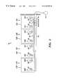
- FIG. 1illustrates a perspective view of an inflatable cushioning device of the present invention
- FIG. 2illustrates a partial cross-sectional view of a support cell including a reforming element and an intake valve
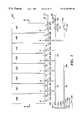
- FIG. 3illustrates an end view of a support system apparatus
- FIG. 4illustrates a plan view of another embodiment of the support system apparatus including a plurality of controlled support zones
- FIG. 5illustrates a cross-sectional view of the support system apparatus taken along the line 5 — 5 of FIG. 4;
- FIG. 6illustrates an example of a pressure distribution in a plurality of zones in the support system apparatus of FIG. 5;
- FIG. 7illustrates a plan view of another embodiment of the support system apparatus including an alternating pressure system
- FIG. 8illustrates a cross-sectional view of the support system apparatus taken along the line 8 — 8 of FIG. 7;
- FIG. 9illustrates a first pressure distribution pattern provided by the alternating pressure system in the plurality of support cells of FIG. 8;
- FIG. 10illustrates a second pressure distribution pattern provided by the alternating pressure system in the plurality of support cells of FIG. 8;
- FIG. 11illustrates a cut-away perspective view of a mattress cushioning device
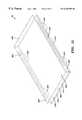
- FIG. 12illustrates a perspective view of the mattress cushioning device with an outer cover
- FIG. 13illustrates a cross-sectional view of a patient lying on a conventional mattress
- FIG. 14illustrates a cross-sectional view of the patient being supported by the cushioning device of the present invention, wherein a low interface pressure is provided under the patient;
- FIG. 15illustrates a perspective view of a chair seat cushioning device
- FIG. 16illustrates a plan view of another embodiment of a cushion device with alternating pressure support cells
- FIG. 17illustrates a perspective view of a coiled spring resilient support
- FIG. 18illustrates a perspective view of a bellows resilient support.
- the cushioning device 10can be used in combination with any support device where self-adjusting dynamic pressure support of a person or patient 56 (FIG. 14) is required.
- the support devicemay include a mattress, sofa, seat, etc.
- the cushioning device 10includes a support system apparatus 12 comprising at least one support cell 14 , a sleeve apparatus 16 (FIG. 5 ), a jacket 18 (FIG. 5 ), and a topper cushion 20 .
- the support system apparatus 12includes at least one support cell 14 for providing lifting support for a patient 56 .
- An intake valve 40 and an exhaust valve 42are included in each support cell 14 .
- the cushion device 10also includes two end walls 24 , 26 , and two side walls 28 , 30 .
- the end walls 24 , 26 , and the side walls 28 , 30can be formed from a resilient material such as foam or rubber.
- the topper cushion 20rests on top of the jacket 18 and provides further cushioning to a body.
- the topper cushion 20can be composed of any resilient material, for example, foam, down feathers, an inflatable air cushion, etc.
- FIG. 2illustrates a partial cross-sectional view of the support cell 14 A including an envelope 34 A and a reforming element 32 A.
- the envelope 34 Acontains a fluid 36 .
- the application of an external load on the envelope 34 Acauses the envelope 34 A to deform into a compressed form.
- the reforming element 32 Aprovides a reforming force to the interior surface 38 A of the envelope 34 A.
- the reforming forcecauses the envelope 34 A to return to its original form when the external load is removed from the envelope 34 A.
- the reforming element 32 Ais preferably a resilient foam material, however, other resilient means can be used such as a coiled spring 500 (FIG. 17) or a bellows 520 (FIG. 18 ).
- the coiled spring 500is surrounded by a resilient material 502 .
- the bellows 520may be formed from a pliable resilient material such as plastic and filled with a fluid such as air.
- FIGS. 1 and 3An example of a support system apparatus 12 for a mattress includes a plurality of support cells 14 A, 14 B, 14 C, and 14 D is illustrated in FIGS. 1 and 3.
- Intake valves 40 A, 40 B, 40 C, 40 D, and exhaust valves 42 A, 42 B, 42 C and 42 Dare also illustrated in FIG. 3 .
- Each intake valve 40includes an intake check valve 48 allowing fluid 36 to flow into the support cell 14 , while preventing fluid 36 from flowing out of the support cell 14 .
- Each exhaust valve 42includes an exhaust check valve 50 allowing fluid 36 to flow out of the support cell 14 , while preventing fluid 36 from flowing back into the support cell 14 .
- Each exhaust valve 42is connected to an exhaust conduit 60 included in an exhaust control system 46 .
- Each intake valve 40is preferably connected to an intake conduit 58 included in an intake control system 44 .
- the intake control system 44is connected to a fluid supply reservoir 52 .
- the exhaust control system 46is connected to a fluid exhaust reservoir 54 .
- the fluid 36 included in the fluid supply reservoir 52 and the fluid exhaust reservoir 54is air, however, any suitable fluid 36 (e.g. water or nitrogen) can be used.
- the fluid supply reservoir 52 and the fluid exhaust reservoir 54may comprise the same reservoir, and may comprise an ambient source of fluid 36 such as atmospheric air.
- the weight of a body such as a patient 56 resting on the cushion device 10deforms the envelope 34 in each support cell 14 .
- the pressure of the fluid 36 within each envelope 34increases as the volume of the envelope 34 decreases under deformation.
- the fluid 36 in each envelope 34flows out of the envelope 34 through a corresponding exhaust valve 42 and into the exhaust control system 46 (FIGS. 1 and 3 ).
- the fluid 36flows from the exhaust control system 46 into the fluid exhaust reservoir 54 .
- the area of the envelope 34 supporting the loadincreases. Equilibrium is achieved when the forces within the envelope 34 , including the pressure of the fluid 54 within the envelope 34 multiplied by the area of the envelope 34 supporting the load, plus the force provided by the reforming element 32 , equal the weight of the load.
- a controllable pressure relief valve 62is included in the exhaust control system 46 and is attached to an end 64 of the exhaust conduit 60 .
- the outlet 66 of the controllable pressure relief valve 62is attached to the fluid exhaust reservoir 54 .
- the controllable pressure relief valve 62controls the maximum pressure level of the fluid 36 in the exhaust conduit 60 and in each envelope 34 in each support cell 14 .
- a rotatable knob 68 or other adjusting mechanism on the controllable pressure relief valve 62allows a user to adjust the regulated maximum pressure level. Different selected maximum allowable pressures in the support cells 14 A, 14 B, 14 C, and 14 D allow the support system apparatus 12 to accommodate patients 56 of different weights.
- the setting of different maximum allowable pressures in the support cells 14 A, 14 B, 14 C, and 14 Dallows different degrees of conformation between the patient 56 and the surface of each envelope 34 .
- the maximum pressureis preferably set to ensure that the interface pressure under the entire contact surface of the patient 56 is below the pressure that may cause tissue damage.
- the cushioning device 10 of the present inventionallows a user in the field to adjustably set the maximum pressure level in each support cell 14 .
- the maximum pressureis preferably above about 6 inches of water but is optimally in the range of about 8 to 12 inches of water. Other ranges may also be used, depending on operational requirements, user preferences, etc.
- FIG. 13illustrates the patient 56 resting on a conventional mattress 72 .
- High pressure regions on the patient 56are indicated by the force arrows PA, PB, PC, PD, and PE.
- FIG. 14illustrates the patient 56 resting on a cushion device 10 of the present invention.
- the cushion device 10provides a low uniform interface pressure PX that supports the entire contact surface of the patient 56 . This interface pressure is below the pressure that may cause tissue damage, thereby preventing the formation of pressure sores and other injuries.
- each envelope 34As the weight of the patient 56 is removed from each support cell 14 , the reforming element 32 (FIG. 2) in each envelope 34 exerts a reforming force on the interior surface 38 of each envelope 34 . As each envelope 34 expands, a partial vacuum is created in the interior space 70 of each envelope 34 . The vacuum draws the fluid 36 from the fluid supply reservoir 52 into the intake control system 44 . Next, the fluid 36 is drawn from the intake control system 44 through a corresponding intake valve 40 into the interior space 70 of each envelope 34 .
- the support system apparatus 12 of the present inventionalso has the ability to self-adjust every time a patient 56 moves, or is repositioned on, the support system apparatus 12 .
- the support cells 14 within the support system apparatus 12automatically inflate or deflate to restore the low interface pressure PX under the entire patient (FIG. 14 ).
- Each support zone “A,” “B,” and “C”includes at least one support cell 14 .
- Each support cell 14includes at least one intake valve 40 and at least one exhaust valve 42 .
- each intake valve 40 A- 40 His connected to the intake control system 44 .
- the exhaust valves 42 A and 42 B in zone “C”are connected to an exhaust control system 82 .
- the exhaust valves 42 C, 42 D, 42 E and 42 F in zone “B”are connected to an exhaust control system 84 .
- the exhaust valves 42 G and 42 H in zone “A”are connected to an exhaust control system 86 .
- Each intake valve 40 A- 40 Hallows fluid 36 to flow into each support cell 14 A- 14 H, respectively, while preventing fluid 36 from flowing back out of each support cell 14 A- 14 H, respectively.
- Each exhaust valve 42 A- 42 Hallows fluid 36 to flow out of each support cell 14 A- 14 H, respectively, while preventing fluid 36 from flowing back into each support cell 14 A- 14 H, respectively.
- the intake control system 44is connected to the fluid supply reservoir 52 .
- the exhaust control systems 82 , 84 , and 86are connected to the fluid exhaust reservoir 54 .
- the fluid 36 included in the fluid supply reservoir 52 and the fluid exhaust reservoir 54is atmospheric air, however, other fluids 36 can be used.
- Each exhaust control system 82 , 84 , and 86includes a pressure relief valve 88 , 90 , and 92 , respectively, that maintains the pressure of the fluid 36 in zones “A,” “B,” and “C” below a selected level.
- a rotatable knob 68 or other adjusting system included in each pressure relief valve 88 , 90 , and 92allows a user to set the maximum pressure level of the fluid 36 in each zone “A,” “B,” and “C.”
- FIG. 5illustrates a cross-sectional view of the support system apparatus 80 and zones “A,” “B,” and “C” taken along line 5 — 5 of FIG. 4 .
- Atomospheric airis supplied to the fluid supply reservoir 52 , there is no need for blowers or pumps to supply the pressurized fluid 36 .
- Each support cell 14 A- 14 Hself-inflates when the weight of the patient 56 is removed as described above for the support system apparatus 12 .
- Each exhaust control system 82 , 84 and 86allows the maximum pressure level of the fluid 36 in each zone “A,” “B,” and “C” to be individually set.
- FIG. 5illustrates a cross-sectional view of the support system apparatus 80 and zones “A,” “B,” and “C” taken along line 5 — 5 of FIG. 4 .
- FIG. 6illustrates an example of different pressure levels set in zones “A,” “B,” and “C.”
- a different level of pressure or firmnesscan be provided for the upper, middle, and lower portions of the patient's body 56 .
- the sleeve apparatus 16includes a cell cover 96 surrounding each support cell 14 .
- Each support cell 14Each cell cover 96 A, 96 B, 96 C, 96 D, 96 E, 96 F, 96 G, and 96 H, is attached to each adjacent cell cover 96 by connections 98 A, 98 B, 98 C, 98 D, 98 E, 98 F, and 98 G.
- the connections 98 A- 98 Gcan be formed by a glued, heat sealed or sewn connection.
- Each cell cover 96allows the exterior surface 100 of a corresponding envelope 34 to slide freely along an interior surface 102 of the cell cover 96 , without transmitting this movement to an exterior surface 104 of the cell cover 96 .
- the support cell 14 Aincludes the envelope 34 A, which is surrounded by the cell cover 96 A.
- the exterior surface 100 A of the envelope 34 Ais free to slide along the interior surface 102 A of the cell cover 96 A. This sliding movement is not transmitted to the stationary exterior surface 104 A of the cell cover 96 A.
- the stationary exterior surface 104 Ais located on the side of the outer cover 22 (FIG. 11) on which the patient 56 is lying, so that the sliding movement of the envelope 34 A is not transmitted to the patient. Therefore, the cell covers 96 of the sleeve apparatus 16 prevent frictional shear force abrasion damage to the skin of the patient 56 .
- a support system apparatus 106provides an additional alternating pressure system 130 for providing alternating supply pressure to a plurality of zones “E” and “F” as illustrated in FIG. 7 .
- the alternating pressure system 130can include any means for supplying the fluid 36 under pressure including a pump, compressor, etc. Also, included in the alternating pressure system 130 is any means such as a valve (not shown) for periodically switching the pressurized fluid 36 between conduit 132 and 134 .
- Each support zone “E” and “F,”comprises at least one support cell 14 .
- Each support cell 14includes at least one intake valve 40 and at least one port 43 .
- Each intake valve 40includes a check valve (not shown) allowing fluid 36 to flow into the support cell 14 , while preventing fluid 36 from flowing out of the support cell 14 .
- Each port 43allows unimpeded fluid 36 flow into or out of the support cell 14 .
- each intake valve 40 J- 40 Qis connected to the intake control system 44 .
- the ports 43 Q, 430 , 43 M, and 43 K in zone “E”are connected to conduit 108 .
- the ports 43 J, 43 L, 43 N, and 43 P in zone “F”are connected to conduit 110 .
- a first end 112 of conduit 108is connected to a check valve 114 , and a second end 118 of conduit 108 is connected to a shut off valve 120 .
- a first end 122 of conduit 110is connected to a check valve 124 , and a second end 126 of the conduit 110 is connected to a shut off valve 128 .
- Conduit 132connects the shut off valve 120 with the alternating pressure system 130 .
- Conduit 134connects the shut off valve 128 with the alternating pressure system 130 .
- Conduits 136 and 138connect the check valve 114 and the check valve 124 with the exhaust control system 140 .
- the shut off valve 120can be a “quick disconnect” type that allows fluid 36 to flow through the shut off valve 120 when the conduit 132 is connected, and prevents any flow of the fluid 36 flow when the conduit 132 is disconnected.
- the shut off valve 128can also be a “quick disconnect” type that allows fluid 36 to flow through the shut off valve 128 when the conduit 134 is connected, and prevents any flow of the fluid 36 when the conduit 134 is disconnected.
- Check valve 114allows fluid 36 to flow from conduit 108 into conduit 136 , and prevents fluid 36 from flowing from conduits 136 and 138 into conduit 108 .
- Check valve 124allows fluid 36 to flow from conduit 110 into conduit 138 , and prevents fluid 36 from flowing from conduits 138 and 136 into conduit 110 .
- the exhaust control system 140includes a pressure relief valve 142 similar to the pressure relief valves described above.
- Each intake valve 40 J- 40 Qallows fluid 36 to flow into each support cell 14 J- 14 Q, respectively, while preventing fluid 36 from flowing out of each support cell 14 J- 14 Q, respectively, (FIG. 7 ).
- Each intake valve 40 J- 40 Qis connected to the intake control system 44 , which is connected to the fluid supply reservoir 52 .
- the fluid 36 included in the fluid supply reservoir 52is atmospheric air, however, any other suitable fluids can be used.
- Conduits 108 and 110are connected through ports 43 J- 43 Q to the zones “E” and “F.” Therefore, the pressure relief valve 142 maintains the pressure of the fluid 36 below a selected level in zones “E” and “F.”
- a rotatable knob 144 or other adjusting system included in the pressure relief valve 142allows a user to set the maximum pressure of the fluid 36 in the zones “E” and “F.”
- the pressure relief valve 142is connected to the fluid exhaust reservoir 54 .
- the alternating pressure system 130supplies alternating high and low pressure fluid 36 to conduits 108 and 110 .
- conduit 132is connected to shut off valve 120
- conduit 134is connected to shut off valve 128
- the alternating pressureis supplied to conduits 108 and 110 .
- the conduits 108 and 110supply the alternating fluid 36 pressure to zones “E” and “F.”
- a high pressure fluid 36may be supplied to the conduit 108 from the alternating pressure system 130 , and a low pressure fluid 36 may be supplied to conduit 110 , creating a high fluid 36 pressure in zone “E” and a low fluid 36 pressure in zone “F.”
- the fluid 36flows through check valve 114 to conduit 136 and 138 , but is prevented by check valve 124 from flowing into conduit 110 .
- the fluid 36 flow provided by the alternating pressure system 130is much higher than the flow passing out through the pressure relief valve 142 , so that the high pressure fluid 36 fills the zone “E” support cells 14 K, 14 M, 140 , and 14 Q as illustrated in FIG. 8 .
- FIG. 9illustrates the pressure levels in the support cells in zones “E” and “F”. For this condition, the support cells 14 in zone “E” rise under the patient 56 and the support cells 14 in zone “F” lower under the patient 56 .
- a high fluid 36 pressureis supplied to conduit 110 and a low fluid 36 pressure is supplied to conduit 108 , forcing a high pressure fluid 36 into zone “F” and a low pressure fluid 36 into zone “E”.
- the fluid 36flows through check valve 124 to conduit 138 and 136 , but is prevented by check valve 114 from flowing back into the conduit 108 .
- the fluid 36 flow provided by the alternating pressure system 130is much higher than the flow passing out through the pressure relief valve 142 , so that the high pressure fluid 36 fills the zone “F” support cells 14 J, 14 L, 14 N, and 14 P.
- FIG. 10illustrates the pressure levels in the support cells 14 in zones “E” and “F.” For this condition, the zone “F” support cells 14 rise under the patient 56 and the zone “E” support cells 14 lower under the patient 56 .
- the alternating rising and lowering of the support cells 14 in the zones “E” and “F” under the patient 56provides beneficial movement of the skeleton and tissue in the patient 56 .
- the movementhelps stimulate circulation and lymph fluid movement in the patient 56 .
- the alternating pressure system 130includes a computerized control system 131 that is programmed to supply alternating pressures to a plurality of support cells 14 in any sequence that is desired by the user.
- FIG. 16Another embodiment of a support system apparatus 180 with a plurality of support cells 14 is illustrated in FIG. 16 .
- This embodimentshows another example of the shape of support cells 14 AA- 14 SS.
- the support cells 14can be inter-connected in a manner similar to the support system apparatus 12 and the support system apparatus 106 to provide the support system apparatus 180 with self-inflating, self-adjusting, zoned pressure control, and alternating pressure support and movement to a person lying on the support system apparatus 180 .
- the computerized control system 131 included in the alternating pressure system 130may be programmed to supply alternating pressures to the plurality of the support cells 14 AA- 14 SS in any sequence that is desired by the user.
- FIG. 11illustrates a cut-away perspective view of a mattress cushioning device 200 .
- the mattress cushioning device 200includes a torso support system 220 , a heel support system 240 , and a sleeve apparatus 260 , the jacket 18 , the topper cushion 20 , and the outer cover 22 .
- the torso support system apparatus 220includes a plurality of support cells 14 , the side wall 28 , the end wall 26 , and the side wall 30 .
- the side walls 28 and 30 and the end wall 26are formed from a resilient material.
- the sleeve apparatus 260includes cell covers 96 . Each cell cover 96 surrounds a support cell 14 to prevent sliding and frictional motion to be transmitted to the patient 56 .
- the support cells 14provide self-inflating and self-adjusting pressure support to the torso region of a patient 56 resting on the support system apparatus 220 .
- the support cells 14extend in a longitudinal direction of the mattress cushioning device 200 . Also, alternating pressure can be applied to the individual support cells 14 under the patient 56 to provide therapeutic movement to the body of the patient 56 .
- the heel support system apparatus 240includes a plurality of support cells 14 , the end wall 29 , a side wall 242 , and a side wall 244 .
- the heel support system 240provides support for the heel area of a patient 56 .
- the support cells 14extend in a transverse direction on the mattress cushioning device 200 .
- the jacket 18surrounds the torso support system apparatus 220 and the heel support system apparatus 240 .
- the topper cushion 20lies on top of the jacket 18 and provides further cushioning and comfort to the patient 56 .
- the topper cushion 20can be composed of any resilient material, for example, foam, down feathers, an inflatable air cushion, etc.
- the outer cover 22is illustrated in FIGS. 11 and 12.
- the outer cover 22 of the mattress cushioning device 200provides a low friction and low shear surface further protecting the patient 56 from frictional tissue damage. Additionally, the outer cover 22 provides a waterproof and stain resistant surface.
- the outer cover 22can be made from an anti-microbial type material.
- the outer cover 22includes end walls 202 and 204 , side walls 206 and 208 , a top wall 210 and a bottom wall 212 .
- a closure 214joins an upper portion 216 to a lower portion 218 of the outer cover 22 .
- the closure 214may comprise, for example, a zipper, snaps, hook and eye fasteners, etc.
- the side walls 206 and 208can include stretchable panels 222 and 224 that allows the outer cover 22 to expand and contract as the support cells 14 rise and fall within the outer cover 22 .
- the displacement of the support cells 14is accommodated by the stretchable panels 222 and 224 so that stretching of the top wall 210 is prevented.
- the top walldoes not transmit shear forces to the patient 56 resting on the top wall 210 .
- Flexible handles 226can be attached to the outer cover 22 to allow a user to grasp and move the mattress cushioning device 200 .
- the seat cushioning device 260includes three supporting sections 262 , 264 , and 266 . Each section 262 , 264 , and 266 includes at least one support cell 14 .
- the support cells 14can be inter-connected in a manner similar to the support system apparatus 12 , the support system apparatus 180 , and the support system apparatus 106 to provide the seat cushioning device 260 with self-inflating, self-adjusting, zoned pressure control, and alternating pressure support and movement to a person sitting on the seat cushioning device 260 .
- the supporting sections 262 , 264 , and 266may each include an intake valve 263 and an exhaust valve 265 .
- the exhaust valves 265are interconnected by an exhaust control system 267 having a controllable pressure relief valve 269 .
- the pressure relief valve 269is provided to control the maximum pressure level of the fluid in each of the supporting sections 262 , 264 , and 266 .
- the cushioning device of the present inventionis suitable for providing self-inflating, self-adjusting, zoned pressure control, and alternating pressure support to any supported body.
- the cushioning device of the present inventionis suitable for any application where low interface pressure is required between the cushioning device and the surface of the body being supported.
Landscapes
- Health & Medical Sciences (AREA)
- Nursing (AREA)
- Life Sciences & Earth Sciences (AREA)
- Animal Behavior & Ethology (AREA)
- General Health & Medical Sciences (AREA)
- Public Health (AREA)
- Veterinary Medicine (AREA)
- Mattresses And Other Support Structures For Chairs And Beds (AREA)
- Invalid Beds And Related Equipment (AREA)
- Buffer Packaging (AREA)
Abstract
Description
Claims (20)
Priority Applications (17)
| Application Number | Priority Date | Filing Date | Title |
|---|---|---|---|
| US09/295,139US6269505B1 (en) | 1999-04-20 | 1999-04-20 | Inflatable cushioning device with manifold system |
| EP00928223AEP1178746B1 (en) | 1999-04-20 | 2000-04-19 | Inflatable cushioning device with manifold system |
| DK00928223TDK1178746T3 (en) | 1999-04-20 | 2000-04-19 | Inflatable cushion with manifold system |
| ES00928223TES2264933T3 (en) | 1999-04-20 | 2000-04-19 | INFLATABLE SHOCK ABSORBER DEVICE WITH MULTIPLE SYSTEM. |
| DE20023705UDE20023705U1 (en) | 1999-04-20 | 2000-04-19 | Body support e.g. mattress, sofa, chair cushion, for use with cushioning device, has non-powered manifold system operatively attached to several self-inflating fluid cells |
| AU46488/00AAU779556B2 (en) | 1999-04-20 | 2000-04-19 | Inflatable cushioning device with manifold system |
| CA002370218ACA2370218C (en) | 1999-04-20 | 2000-04-19 | Inflatable cushioning device with manifold system |
| PCT/US2000/010575WO2000062648A1 (en) | 1999-04-20 | 2000-04-19 | Inflatable cushioning device with manifold system |
| AT00928223TATE331454T1 (en) | 1999-04-20 | 2000-04-19 | INFLATABLE CUSHION ARRANGEMENT WITH DISTRIBUTION SYSTEM |
| DE60029098TDE60029098T2 (en) | 1999-04-20 | 2000-04-19 | INFLATABLE CUSHION ASSEMBLY WITH DISTRIBUTION SYSTEM |
| JP2000611791AJP2003507085A (en) | 1999-04-20 | 2000-04-19 | Inflatable cushion device with manifold system |
| US09/867,308US6826795B2 (en) | 1999-04-20 | 2001-05-29 | Inflatable cushioning device with manifold system |
| ZA200108659AZA200108659B (en) | 1999-04-20 | 2001-10-22 | Inflatable cushioning device with manifold system. |
| US10/202,138USRE44584E1 (en) | 1999-04-20 | 2002-07-23 | Inflatable cushioning device with manifold system |
| US10/404,962US8122545B2 (en) | 1999-04-20 | 2003-03-31 | Inflatable cushioning device with manifold system |
| US11/041,758US10357114B2 (en) | 1999-04-20 | 2005-01-24 | Inflatable cushioning device with manifold system |
| US11/841,047US20080028534A1 (en) | 1999-04-20 | 2007-08-20 | Mattress having three separate adjustable pressure relief zones |
Applications Claiming Priority (1)
| Application Number | Priority Date | Filing Date | Title |
|---|---|---|---|
| US09/295,139US6269505B1 (en) | 1999-04-20 | 1999-04-20 | Inflatable cushioning device with manifold system |
Related Child Applications (4)
| Application Number | Title | Priority Date | Filing Date |
|---|---|---|---|
| US09/867,308DivisionUS6826795B2 (en) | 1999-04-20 | 2001-05-29 | Inflatable cushioning device with manifold system |
| US09/867,308ContinuationUS6826795B2 (en) | 1999-04-20 | 2001-05-29 | Inflatable cushioning device with manifold system |
| US10/202,138ReissueUSRE44584E1 (en) | 1999-04-20 | 2002-07-23 | Inflatable cushioning device with manifold system |
| US11/841,047Continuation-In-PartUS20080028534A1 (en) | 1999-04-20 | 2007-08-20 | Mattress having three separate adjustable pressure relief zones |
Publications (1)
| Publication Number | Publication Date |
|---|---|
| US6269505B1true US6269505B1 (en) | 2001-08-07 |
Family
ID=23136393
Family Applications (4)
| Application Number | Title | Priority Date | Filing Date |
|---|---|---|---|
| US09/295,139Expired - LifetimeUS6269505B1 (en) | 1999-04-20 | 1999-04-20 | Inflatable cushioning device with manifold system |
| US09/867,308Expired - LifetimeUS6826795B2 (en) | 1999-04-20 | 2001-05-29 | Inflatable cushioning device with manifold system |
| US10/202,138Expired - LifetimeUSRE44584E1 (en) | 1999-04-20 | 2002-07-23 | Inflatable cushioning device with manifold system |
| US10/404,962Expired - Fee RelatedUS8122545B2 (en) | 1999-04-20 | 2003-03-31 | Inflatable cushioning device with manifold system |
Family Applications After (3)
| Application Number | Title | Priority Date | Filing Date |
|---|---|---|---|
| US09/867,308Expired - LifetimeUS6826795B2 (en) | 1999-04-20 | 2001-05-29 | Inflatable cushioning device with manifold system |
| US10/202,138Expired - LifetimeUSRE44584E1 (en) | 1999-04-20 | 2002-07-23 | Inflatable cushioning device with manifold system |
| US10/404,962Expired - Fee RelatedUS8122545B2 (en) | 1999-04-20 | 2003-03-31 | Inflatable cushioning device with manifold system |
Country Status (11)
| Country | Link |
|---|---|
| US (4) | US6269505B1 (en) |
| EP (1) | EP1178746B1 (en) |
| JP (1) | JP2003507085A (en) |
| AT (1) | ATE331454T1 (en) |
| AU (1) | AU779556B2 (en) |
| CA (1) | CA2370218C (en) |
| DE (2) | DE20023705U1 (en) |
| DK (1) | DK1178746T3 (en) |
| ES (1) | ES2264933T3 (en) |
| WO (1) | WO2000062648A1 (en) |
| ZA (1) | ZA200108659B (en) |
Cited By (71)
| Publication number | Priority date | Publication date | Assignee | Title |
|---|---|---|---|---|
| US6370716B1 (en)* | 1999-04-20 | 2002-04-16 | John W. Wilkinson | Inflatable cushioning device with tilting apparatus |
| US20020148046A1 (en)* | 2001-03-19 | 2002-10-17 | Shahzad Pirzada | Fluid filled support with a portable pressure adjusting device |
| US6564411B2 (en)* | 2001-03-19 | 2003-05-20 | Shahzad Pirzada | Active fluid channeling system for a bed |
| US20030208849A1 (en)* | 1999-04-20 | 2003-11-13 | Wilkinson John W. | Inflatable cushioning device with manifold system |
| US6711771B2 (en)* | 1999-05-03 | 2004-03-30 | Huntleigh Technology Plc | Alternating pad |
| US20040068801A1 (en)* | 2002-10-10 | 2004-04-15 | Wilkinson John W. | Pressure equalization apparatus |
| US6739009B2 (en)* | 2000-05-26 | 2004-05-25 | Del Drago Marcantonio | Supporting device, notably mattress, mattress support or for a seat |
| US6745420B2 (en)* | 2001-03-07 | 2004-06-08 | Gualtiero G. Giori | Adjustable foam and coil spring mattress combination |
| US6810542B1 (en) | 2002-03-18 | 2004-11-02 | Charles H. Mitchell | Lymphatic pump apparatus |
| US20040222684A1 (en)* | 2002-11-22 | 2004-11-11 | Schukra Of North America | Self inflating pneumatic seat cushion apparatus and method |
| US20050005363A1 (en)* | 2001-10-30 | 2005-01-13 | Gualtiero Giori | Pressure adjustable foam support apparatus |
| US6859967B2 (en) | 2002-02-22 | 2005-03-01 | Samuel W. Harrison | Overlay mattress |
| US20050125905A1 (en)* | 1999-04-20 | 2005-06-16 | John Wilkinson | Inflatable cushioning device with manifold system |
| US6922863B2 (en)* | 2001-03-07 | 2005-08-02 | Gualtiero G. Giori | Adjustable foam mattress |
| US20050177952A1 (en)* | 2004-02-13 | 2005-08-18 | Wilkinson John W. | Discrete cell body support and method for using the same to provide dynamic massage |
| US20060075569A1 (en)* | 2002-09-17 | 2006-04-13 | Gino Giori | Adjustable foam mattress |
| US20070113352A1 (en)* | 2005-08-10 | 2007-05-24 | Craig Poulos | Therapeutic mattress |
| US20070151033A1 (en)* | 2006-01-04 | 2007-07-05 | Wyatt Charles C | Patient support surface |
| US20070186349A1 (en)* | 2006-02-10 | 2007-08-16 | Scott Technology Llc | Self inflating air mattress |
| US20080235875A1 (en)* | 2007-03-28 | 2008-10-02 | Stryker Corporation | Maternity bed and patient lying surface therefor |
| WO2009102936A1 (en)* | 2008-02-14 | 2009-08-20 | Kingsdown, Inc. | Apparatuses and methods for single-sided zoned mattress rotation |
| RU2372825C1 (en)* | 2008-03-21 | 2009-11-20 | Юлай Хакимович Байчурин | Method of accelerating charging of multi-tube inflatable products |
| US7698765B2 (en) | 2004-04-30 | 2010-04-20 | Hill-Rom Services, Inc. | Patient support |
| US20100146709A1 (en)* | 2008-12-17 | 2010-06-17 | Stryker Corporation | Patient support |
| US20100180384A1 (en)* | 2005-03-28 | 2010-07-22 | B.G. Industries, Inc. | Mattress |
| US20100281618A1 (en)* | 2009-05-08 | 2010-11-11 | Span-America Medical Systems, Inc. | Internal structural configurations of bladders used in patient support systems |
| US20100318239A1 (en)* | 2008-02-14 | 2010-12-16 | Kingsdown, Inc | Apparatuses and methods providing variable support and variable comfort control of a sleep system and automatic adjustment thereof |
| US20100317930A1 (en)* | 2008-02-14 | 2010-12-16 | Kingsdown, Inc. | Apparatuses and methods for evaluating a person for a sleep system |
| US20110010014A1 (en)* | 2008-02-25 | 2011-01-13 | Kingsdown, Inc. | Systems and methods for controlling a bedroom environment and for providing sleep data |
| WO2011006093A1 (en)* | 2009-07-09 | 2011-01-13 | Kreg Medical, Inc. | Adjustable therapeutic mattress |
| US20110010249A1 (en)* | 2008-03-21 | 2011-01-13 | Oexman Robert D | Methods and apparatuses for providing a sleep system having customized zoned support and zoned comfort |
| US20110041592A1 (en)* | 2008-06-26 | 2011-02-24 | Kingsdown, Inc. | Methods and apparatuses for comfort/support analysis of a sleep support member |
| US20110072584A1 (en)* | 2006-12-20 | 2011-03-31 | Hornbach David W | Cable conduit for hospital bed |
| US8108957B2 (en) | 2007-05-31 | 2012-02-07 | Hill-Rom Services, Inc. | Pulmonary mattress |
| US20120065560A1 (en)* | 2010-09-15 | 2012-03-15 | Kenneth Scott Siegner | Support surface system providing simultaneous alternating pressure and low air loss therapies |
| US20130107506A1 (en)* | 2011-10-27 | 2013-05-02 | Ibtesam M.Y. MUSTAFA | Cushioned cover for traffic structures |
| USD690424S1 (en) | 2011-01-26 | 2013-09-24 | Sage Products, Inc. | Set of components for a patient repositioning system |
| US20130291310A1 (en)* | 2012-05-07 | 2013-11-07 | Caremed Supply Inc. | Sensing device for air cushion bed |
| US8584286B2 (en) | 2010-04-27 | 2013-11-19 | Ec Service Inc. | Systems and methods for providing a self deflating cushion |
| US8595873B2 (en) | 2010-12-08 | 2013-12-03 | Hill-Rom Services, Inc. | Mattress deflation management |
| US20140047645A1 (en)* | 2011-12-05 | 2014-02-20 | Ceragem Cellupedic. Co., Ltd | Mattress and method of adjusting pressure of mattress |
| US20140101862A1 (en)* | 2011-07-28 | 2014-04-17 | Tokai Rubber Industries, Ltd. | Mattress and control method thereof |
| WO2014063132A1 (en)* | 2012-10-19 | 2014-04-24 | Wilkinson Jeffrey W | Cushioning device and method of cushioning a body |
| US8719984B2 (en) | 2009-10-02 | 2014-05-13 | Sizewise Rentals, L.L.C. | Segmented air foam mattress |
| US8789224B2 (en) | 2000-11-07 | 2014-07-29 | Tempur-Pedic Managemant, LLC | Therapeutic mattress assembly |
| US8966689B2 (en)* | 2012-11-19 | 2015-03-03 | Select Comfort Corporation | Multi-zone fluid chamber and mattress system |
| WO2015053804A3 (en)* | 2013-01-28 | 2015-07-02 | Arnold Balonick | Air cylinders for mattress |
| US9078795B1 (en)* | 2014-09-08 | 2015-07-14 | Wcw, Inc. | Cushioning device and method of cushioning a body |
| US20150265065A1 (en)* | 2014-03-18 | 2015-09-24 | Dreamwell, Ltd. | Accelerated calibration system for a smart response technology mattress |
| US20150320230A1 (en)* | 2014-05-09 | 2015-11-12 | Dreamwell, Ltd. | Firmness control for a smart response technology body support |
| US20160018279A1 (en)* | 2013-03-13 | 2016-01-21 | Korea Institute Of Industrial Technology | Apparatus for sensing operation of air cushion and method therefor |
| US9271579B2 (en) | 2013-04-05 | 2016-03-01 | Rapid Air Llc | Adjustable mattress with foam inserts and air chambers |
| US20160095445A1 (en)* | 2012-02-21 | 2016-04-07 | Hill-Rom Services, Inc. | Topper with targeted fluid flow distribution |
| US9314118B2 (en) | 2011-07-19 | 2016-04-19 | Jiajing Usa, Inc. | Comfort customizable pillow |
| US9820904B2 (en) | 2011-07-13 | 2017-11-21 | Stryker Corporation | Patient/invalid handling support |
| US10058190B1 (en)* | 2012-12-05 | 2018-08-28 | Jiajing Usa, Inc. | Air-foam mattress component |
| US10441087B2 (en) | 2015-02-24 | 2019-10-15 | Sleep Number Corporation | Mattress with adjustable firmness |
| US10716409B2 (en)* | 2014-05-22 | 2020-07-21 | Dreamwell, Ltd. | Smart response technology mattress |
| US11020299B2 (en) | 2012-10-15 | 2021-06-01 | Kap Medical, Inc. | Patient support apparatus and method |
| US20210338506A1 (en)* | 2020-04-30 | 2021-11-04 | Dabir Surfaces, Inc. | Support surface overlay system |
| US11389120B2 (en)* | 2019-05-30 | 2022-07-19 | Hill-Rom Services, Inc. | Mattress having selectable patient weight valve, inductive power, and a digital x-ray cassette |
| EP4066690A1 (en) | 2021-03-30 | 2022-10-05 | Invacare International GmbH | Pressure redistribution mattress |
| US20220354267A1 (en)* | 2019-01-05 | 2022-11-10 | Dockter China Limited | Adjustable Topper and Related Method of Use |
| US11528998B2 (en) | 2018-03-22 | 2022-12-20 | Number Bed Holdings, Llc | Adjustable mattress with foam inserts and air chambers |
| US20230263313A1 (en)* | 2022-02-21 | 2023-08-24 | Sizewise Rentals, L.L.C. | Universal air surface |
| US20230338215A1 (en)* | 2022-04-26 | 2023-10-26 | Dabir Surfaces, Inc. | Support surface overlay system with working fluid recycling |
| US11916508B1 (en) | 2017-03-13 | 2024-02-27 | Aquaenergy Llc | Underground pumped hydro storage |
| US20240115057A1 (en)* | 2016-08-01 | 2024-04-11 | Polygroup Macau Limited (Bvi) | Systems for air mattress pressure control |
| US12150908B2 (en) | 2014-04-18 | 2024-11-26 | Kreg Medical, Inc. | Patient support with stand-up and sit features |
| US12208041B2 (en) | 2008-06-27 | 2025-01-28 | Kreg Medical, Inc. | Bed with frame assembly |
| US12403057B1 (en) | 2021-04-16 | 2025-09-02 | Turn Medical, LLC | Proning face pack |
Families Citing this family (39)
| Publication number | Priority date | Publication date | Assignee | Title |
|---|---|---|---|---|
| US20080028534A1 (en)* | 1999-04-20 | 2008-02-07 | M.P.L. Limited | Mattress having three separate adjustable pressure relief zones |
| US20050090721A1 (en)* | 2001-03-19 | 2005-04-28 | Shahzad Pirzada | Weighing and pump system for a bed |
| US20030226204A1 (en)* | 2002-06-11 | 2003-12-11 | Dodge James R. | Transportable baby crib with leg bumpers |
| GB2391451A (en)* | 2002-08-09 | 2004-02-11 | Chin-Tang Chen | Inflatable pad with built-in pump |
| DE20305023U1 (en) | 2003-03-12 | 2003-07-03 | Thomas GmbH + Co. Technik + Innovation KG, 27432 Bremervörde | Underlay for a human body, in particular, mattress for beds, loungers, armchairs and the like comprises a core with at least one layer of elastic tubes |
| US7260860B2 (en)* | 2004-08-04 | 2007-08-28 | Hill-Rom Services, Inc. | Mattress system for a hospital bed |
| US8650686B2 (en)* | 2004-11-18 | 2014-02-18 | Anodyne Medical Device, Inc. | Adjustable width bariatric transport support surface |
| US20060117486A1 (en)* | 2004-12-03 | 2006-06-08 | Clark Ted D | Mattress repair apparatus |
| WO2006133733A1 (en)* | 2005-06-13 | 2006-12-21 | Flamel Technologies | Oral dosage form comprising an antimisuse system |
| US8015972B2 (en) | 2006-01-03 | 2011-09-13 | Shahzad Pirzada | System, device and process for remotely controlling a medical device |
| US20080040860A1 (en)* | 2006-08-17 | 2008-02-21 | Gaymar Industries, Inc. | Turn-assist with access areas |
| US7441294B2 (en)* | 2007-01-22 | 2008-10-28 | L&P Property Management Company | Bedding or seating product having inflatable concentric air bladders |
| FR2912884B1 (en)* | 2007-02-27 | 2012-09-28 | Hill Rom Ind Sa | "MATTRESS-TYPE SUPPORT DEVICE COMPRISING AT LEAST ONE SOLENOID VALVE FOR CONTROLLING THE SUPPLY / EXHAUST OF FLUID IN SUBSTRATES OF THE MATTRESS" |
| US8033600B2 (en) | 2007-05-29 | 2011-10-11 | Ergoair, Inc. | Seat system with shock- and vibration-reducing bladders |
| FR2917278A1 (en) | 2007-06-18 | 2008-12-19 | Hill Rom Ind S A Sa | MATTRESS-TYPE SUPPORT DEVICE HAVING A HETEROGENEUS INFLATABLE STRUCTURE |
| FR2922439B1 (en) | 2007-10-18 | 2010-12-10 | Hill Rom Ind Sa | METHOD FOR ALTERNATE INFLATION OF AN INFLATABLE CELL SUPPORT DEVICE AND DEVICE FOR IMPLEMENTING IT |
| US20090144904A1 (en)* | 2007-12-10 | 2009-06-11 | David Moye | Inflatable hospital bed and method of using same |
| US7841667B2 (en)* | 2008-04-04 | 2010-11-30 | L&P Property Management Company | Seating support system |
| JP5562060B2 (en) | 2010-02-05 | 2014-07-30 | パラマウントベッド株式会社 | Air mattress |
| US9044367B2 (en)* | 2010-06-12 | 2015-06-02 | American Home Health Care, Inc. | Patient weighing and bed exit monitoring |
| CN103974681B (en)* | 2010-09-01 | 2017-12-26 | 亨特莱技术有限公司 | Patient support and method |
| DE102011075440B4 (en)* | 2011-05-06 | 2014-05-22 | Siemens Aktiengesellschaft | Head support cushion with integrated patient fixation |
| WO2012172421A1 (en)* | 2011-06-16 | 2012-12-20 | Picard Healthcare Technology (Dongguan) Co. Ltd. | Medical air mattress, method to inflate/deflate a medical air mattress and method to incline the bearing surface of a medical air mattress |
| JP5780643B2 (en)* | 2011-07-28 | 2015-09-16 | 住友理工株式会社 | mattress |
| US9131780B2 (en) | 2012-02-14 | 2015-09-15 | Hill-Rom Services, Inc. | Topper with preferential fluid flow distribution |
| US9572433B2 (en) | 2012-08-15 | 2017-02-21 | Hill-Rom Services, Inc. | Systems and methods for directing fluid flow in a mattress |
| US9015885B2 (en) | 2013-02-13 | 2015-04-28 | William Lawrence Chapin | Traveling wave air mattresses and method and apparatus for generating traveling waves thereon |
| WO2014169386A1 (en)* | 2013-04-15 | 2014-10-23 | Promat Inc. | Cushioning device for large animals |
| JP6239863B2 (en)* | 2013-05-20 | 2017-11-29 | 株式会社ウォーキングDay | cushion |
| US11399996B2 (en) | 2013-10-16 | 2022-08-02 | Kuiper Kamradt Llc | Automatic patient turning and lifting method, system, and apparatus |
| WO2016020883A1 (en) | 2014-08-07 | 2016-02-11 | Fakhrizadeh Mohammad | Multi-functional and multipositional bed |
| GB2536637A (en)* | 2015-03-23 | 2016-09-28 | Talar-Made Ltd | An apparatus and method for supporting at least a part of a person and a method of manufacturing an apparatus |
| WO2019147236A1 (en)* | 2018-01-24 | 2019-08-01 | Thinair Surfaces Llc | Support apparatus and method with shear relief |
| EP3667398A1 (en)* | 2016-01-20 | 2020-06-17 | Canon Kabushiki Kaisha | Head mounted device |
| JP2018027303A (en)* | 2016-08-15 | 2018-02-22 | ▲黄▼賢達Huang, Hsien−Ta | Lifting type pillow |
| TWI608836B (en)* | 2016-11-11 | 2017-12-21 | Patient support structure, pressure release module and non-dynamic pressure adjustment method | |
| JP6869925B2 (en)* | 2017-07-27 | 2021-05-12 | ヒル−ロム サービシズ,インコーポレイテッド | Dynamic foam mattress suitable for use in hospital beds of varying length |
| CA3085438A1 (en) | 2019-08-13 | 2021-02-13 | Stryker Corporation | Support apparatus for bariatric person |
| EP4362880A1 (en)* | 2021-06-28 | 2024-05-08 | Arjo IP Holding Aktiebolag | Pneumatic connector assembly, inflatable mattress and patient support apparatus |
Citations (35)
| Publication number | Priority date | Publication date | Assignee | Title |
|---|---|---|---|---|
| US201728A (en) | 1878-03-26 | Improvement in combined bed and life-raft | ||
| US3653083A (en)* | 1970-05-11 | 1972-04-04 | Roy Lapidus | Bed pad |
| US4477935A (en) | 1982-01-08 | 1984-10-23 | Griffin Gordon D | Mattress support system |
| US4644597A (en) | 1983-05-09 | 1987-02-24 | Dynatech, Inc. | Air mattress with pressure relief valve |
| US4662012A (en) | 1983-12-07 | 1987-05-05 | Torbet Philip A | Bed utilizing an air mattress |
| US4686722A (en) | 1983-04-06 | 1987-08-18 | Revalidatie Institut Muiderpoort | Articulated bed with cellular air cushion mattress |
| US4797962A (en) | 1986-11-05 | 1989-01-17 | Air Plus, Inc. | Closed loop feedback air supply for air support beds |
| US4908895A (en) | 1989-03-20 | 1990-03-20 | Walker Robert A | Air mattress |
| US4989283A (en) | 1989-06-12 | 1991-02-05 | Research Development Foundation | Inflation control for air supports |
| US5020176A (en) | 1989-10-20 | 1991-06-04 | Angel Echevarria Co., Inc. | Control system for fluid-filled beds |
| US5033133A (en) | 1990-09-13 | 1991-07-23 | Nissen Sports Academy, Inc. | Seat cushion |
| US5070560A (en) | 1990-10-22 | 1991-12-10 | Healthflex, Inc. | Pressure relief support system for a mattress |
| US5090077A (en) | 1991-01-07 | 1992-02-25 | Health Products, Inc. | Cellular patient support for therapeutic air beds |
| US5090076A (en) | 1990-10-31 | 1992-02-25 | Hans Guldager | Multiple cell inflation element |
| US5142717A (en)* | 1988-10-20 | 1992-09-01 | Sustena, Inc. | Constant pressure load bearing air chamber |
| US5249318A (en) | 1988-05-24 | 1993-10-05 | Loadsman Gerald H | Air support cushion |
| US5267364A (en) | 1992-08-11 | 1993-12-07 | Kinetic Concepts, Inc. | Therapeutic wave mattress |
| US5375273A (en) | 1992-10-29 | 1994-12-27 | Geomarine Systems, Inc. | Lateral rotation therapy mattress system and method |
| US5388292A (en)* | 1991-02-20 | 1995-02-14 | D. Ray Stinson | Fluid filled mattress with foam filled chambers |
| US5487196A (en) | 1994-01-10 | 1996-01-30 | Span America Medical Systems, Inc. | Automated pressure relief mattress support system |
| US5539942A (en) | 1993-12-17 | 1996-07-30 | Melou; Yves | Continuous airflow patient support with automatic pressure adjustment |
| US5542136A (en) | 1994-08-05 | 1996-08-06 | Stryker Corporation | Portable mattress for treating decubitus ulcers |
| US5560057A (en) | 1994-07-01 | 1996-10-01 | Madsen; Roger T. | Turning air mattress |
| US5586346A (en) | 1994-02-15 | 1996-12-24 | Support Systems, International | Method and apparatus for supporting and for supplying therapy to a patient |
| US5594963A (en) | 1992-08-20 | 1997-01-21 | Kinetic Concepts, Inc. | Pressure relief air mattress and related system |
| US5611096A (en) | 1994-05-09 | 1997-03-18 | Kinetic Concepts, Inc. | Positional feedback system for medical mattress systems |
| US5630237A (en) | 1996-04-03 | 1997-05-20 | Ku; Tun-Jen | Foam filled inflatable mat with a peripheral air duct |
| US5634224A (en)* | 1994-08-16 | 1997-06-03 | Gates; Stephen M. | Inflatable cushioning device with self opening intake valve |
| US5634225A (en) | 1995-05-25 | 1997-06-03 | Foamex L.P. | Modular air bed |
| US5659908A (en) | 1993-12-27 | 1997-08-26 | Nishino; Toshio | Air mat and method for manufacturing the mat |
| US5787531A (en) | 1994-07-08 | 1998-08-04 | Pepe; Michael Francis | Inflatable pad or mattress |
| US5794288A (en) | 1996-06-14 | 1998-08-18 | Hill-Rom, Inc. | Pressure control assembly for an air mattress |
| US5873137A (en) | 1996-06-17 | 1999-02-23 | Medogar Technologies | Pnuematic mattress systems |
| US5893184A (en)* | 1997-01-10 | 1999-04-13 | Comfortex Health Care Surfaces | Pressure reducing backrest cushion with selective pressure point relief |
| US6014784A (en) | 1998-10-19 | 2000-01-18 | Taylor; Rex E. | Portable system for generating variable pressure point body support |
Family Cites Families (64)
| Publication number | Priority date | Publication date | Assignee | Title |
|---|---|---|---|---|
| US2433012A (en) | 1942-11-04 | 1947-12-23 | Zalicovitz Morris | Resilient construction for use in furniture |
| US2750606A (en) | 1953-05-14 | 1956-06-19 | Dayton Rubber Company | Foam rubber pillow construction |
| US2779034A (en) | 1954-01-26 | 1957-01-29 | Frank D Arpin | Firmness adjustment for mattresses |
| US3251077A (en) | 1964-03-03 | 1966-05-17 | Ronald H Beckman | Spring assembly |
| US3263247A (en) | 1964-03-03 | 1966-08-02 | Richard R Knittel | Headed hollow body support |
| CA913815A (en) | 1969-05-30 | 1972-10-31 | Convexco Limited | Spring upholstery assembly |
| US3638254A (en) | 1970-05-15 | 1972-02-01 | Uniroyal Inc | Spring |
| US3815887A (en) | 1972-03-21 | 1974-06-11 | Hercules Inc | Plastic spring |
| US3879776A (en) | 1974-01-10 | 1975-04-29 | Morris Solen | Variable tension fluid mattress |
| US4120061A (en) | 1977-10-13 | 1978-10-17 | Clark Harold E | Pneumatic mattress with valved cylinders of variable diameter |
| US4173385A (en) | 1978-04-20 | 1979-11-06 | Bunker Ramo Corporation | Watertight cable connector |
| US4241740A (en) | 1979-03-05 | 1980-12-30 | Brown Joseph W | Bellows type incentive spirometer |
| GB2070174A (en)* | 1980-02-26 | 1981-09-03 | Watkins & Watson Ltd | Conduit connector |
| US4688283A (en) | 1983-10-17 | 1987-08-25 | Jacobson Theodore L | Mattress which conforms to body profile |
| US4679264A (en)* | 1985-05-06 | 1987-07-14 | Mollura Carlos A | Airbed mattress including a regulated, controllable air reservoir therefor |
| US4605582A (en) | 1985-05-23 | 1986-08-12 | American Hospital Supply Corporation | Body support pad |
| US4684201A (en) | 1985-06-28 | 1987-08-04 | Allied Corporation | One-piece crimp-type connector and method for terminating a coaxial cable |
| US4698864A (en) | 1985-11-25 | 1987-10-13 | Graebe Robert H | Cellular cushion |
| US5051673A (en)* | 1985-12-30 | 1991-09-24 | Goodwin Vernon L | Patient support structure |
| US4949413A (en)* | 1985-12-30 | 1990-08-21 | Ssi Medical Services, Inc. | Low air loss bed |
| US4852195A (en) | 1987-10-16 | 1989-08-01 | Schulman David A | Fluid pressurized cushion |
| GB8805962D0 (en) | 1988-03-14 | 1988-04-13 | Huntleigh Technology Plc | Alternating pressure pad |
| WO1989009590A1 (en)* | 1988-03-23 | 1989-10-19 | Robert Ferrand | Patient support system |
| US4995124A (en) | 1988-10-20 | 1991-02-26 | Sustena, Inc. | Constant pressure load bearing air chamber |
| US4895352A (en) | 1989-01-09 | 1990-01-23 | Simmons Company | Mattress or cushion spring array |
| US5584085A (en) | 1989-08-24 | 1996-12-17 | Surgical Design Corporation | Support structure with motion |
| US5029939A (en) | 1989-10-05 | 1991-07-09 | General Motors Corporation | Alternating pressure pad car seat |
| US5052068A (en) | 1989-11-14 | 1991-10-01 | Graebe Robert H | Contoured seat cushion |
| US5062169A (en) | 1990-03-09 | 1991-11-05 | Leggett & Platt, Incorporated | Clinical bed |
| JPH03267013A (en)* | 1990-03-15 | 1991-11-27 | Matsushita Electric Works Ltd | Air matress |
| US5502855A (en) | 1990-11-01 | 1996-04-02 | Graebe; Robert H. | Zoned cellular cushion |
| ES2144044T3 (en)* | 1992-11-13 | 2000-06-01 | Robert H Graebe | CELL PILLOW WITH ZONES. |
| US5652985A (en) | 1994-06-03 | 1997-08-05 | Span-America Medical Systems, Inc. | Self-adjusting pressure relief support system and methodology |
| JPH0838559A (en)* | 1994-08-01 | 1996-02-13 | Satoru Sugiura | Apparatus for making sleeping mat changed to protrude or depress by air pressure |
| US5666681A (en) | 1995-01-03 | 1997-09-16 | Hill-Rom, Inc. | Heel pressure management apparatus and method |
| US5564142A (en) | 1995-05-11 | 1996-10-15 | Liu; Tsung-Hsi | Air mattress collaboratively cushioned with pulsative and static symbiotic sacs |
| US5701622A (en)* | 1996-01-16 | 1997-12-30 | Sentech Medical Systems, Inc. | Pulsating operating table cushion |
| JP3959116B2 (en) | 1996-05-28 | 2007-08-15 | デカ・プロダクツ・リミテッド・パートナーシップ | Steady pressure seat system |
| US5699570A (en) | 1996-06-14 | 1997-12-23 | Span-America Medical Systems, Inc. | Pressure relief valve vent line mattress system and method |
| US5963997A (en)* | 1997-03-24 | 1999-10-12 | Hagopian; Mark | Low air loss patient support system providing active feedback pressure sensing and correction capabilities for use as a bed mattress and a wheelchair seating system |
| US6551450B1 (en) | 1997-10-10 | 2003-04-22 | D2Rm Corp. | Unique air and sonic massaging apparatus |
| US6223369B1 (en)* | 1997-11-14 | 2001-05-01 | Span-America Medical Systems, Inc. | Patient support surfaces |
| AU9587098A (en) | 1998-02-20 | 1999-09-06 | Sand Therapeutic, Inc. | Therapeutic support for the reduction of decubitus ulcers |
| US6269505B1 (en) | 1999-04-20 | 2001-08-07 | M.P.L. Ltd. | Inflatable cushioning device with manifold system |
| US20080028534A1 (en) | 1999-04-20 | 2008-02-07 | M.P.L. Limited | Mattress having three separate adjustable pressure relief zones |
| US6370716B1 (en) | 1999-04-20 | 2002-04-16 | John W. Wilkinson | Inflatable cushioning device with tilting apparatus |
| US10357114B2 (en) | 1999-04-20 | 2019-07-23 | Wcw, Inc. | Inflatable cushioning device with manifold system |
| US7434283B2 (en) | 2004-02-13 | 2008-10-14 | M.P.L. Limited | Discrete cell body support and method for using the same to provide dynamic massage |
| JP2003527150A (en) | 1999-07-06 | 2003-09-16 | ヒル−ロム,インコーポレイティド | Mattress assembly |
| US6317912B1 (en) | 2000-03-08 | 2001-11-20 | Kurtis F. Graebe | Bed mattress with air cells and spring pockets |
| US6461695B1 (en) | 2000-11-14 | 2002-10-08 | Elyakim Schaap | Bellows-shaped article |
| US6687936B2 (en) | 2001-01-18 | 2004-02-10 | Roho, Inc. | Valve for zoned cellular cushion |
| AU2002244012A1 (en) | 2001-02-15 | 2002-09-04 | Hill-Rom Services, Inc. | Self-inflating mattress |
| TW526056B (en) | 2001-03-15 | 2003-04-01 | Huntleigh Technology Plc | Inflatable support |
| DE10236363A1 (en) | 2001-09-03 | 2003-03-27 | Intech Thueringen Gmbh | Medical cushion useful for preventing decubitus ulcers comprises a skin-contacting membrane consisting of a biocompatible matrix containing a molecular sieve loaded with one or more active agents |
| US6859967B2 (en) | 2002-02-22 | 2005-03-01 | Samuel W. Harrison | Overlay mattress |
| ATE415840T1 (en) | 2002-02-28 | 2008-12-15 | Gaymar Ind Inc | SELF-ADJUSTING UPHOLSTERY DEVICE |
| US7617554B2 (en) | 2002-10-10 | 2009-11-17 | M.P.L. Ltd. | Pressure equalization apparatus |
| US6912748B2 (en) | 2002-11-22 | 2005-07-05 | L & P Property Management Company | Self inflating pneumatic seat cushion apparatus and method |
| US6804848B1 (en) | 2003-03-14 | 2004-10-19 | Comfortaire Corporation | High-profile mattress having an upper low-profile module with an air posturizing sleep surface |
| USD506098S1 (en) | 2003-07-10 | 2005-06-14 | Carpenter Co. | Mattress pad configuration |
| US20050050637A1 (en) | 2003-09-05 | 2005-03-10 | Graebe Kurtis F. | Air pillow with four adjustable air pressure chambers |
| US7409735B2 (en) | 2004-08-16 | 2008-08-12 | Hill-Rom Services, Inc. | Dynamic cellular person support surface |
| US7219380B2 (en) | 2005-04-22 | 2007-05-22 | R&D Products, Llc | Multicompartmented air mattress |
- 1999
- 1999-04-20USUS09/295,139patent/US6269505B1/ennot_activeExpired - Lifetime
- 2000
- 2000-04-19AUAU46488/00Apatent/AU779556B2/ennot_activeExpired
- 2000-04-19JPJP2000611791Apatent/JP2003507085A/enactivePending
- 2000-04-19CACA002370218Apatent/CA2370218C/ennot_activeExpired - Lifetime
- 2000-04-19ATAT00928223Tpatent/ATE331454T1/enactive
- 2000-04-19EPEP00928223Apatent/EP1178746B1/ennot_activeExpired - Lifetime
- 2000-04-19DEDE20023705Upatent/DE20023705U1/ennot_activeExpired - Lifetime
- 2000-04-19ESES00928223Tpatent/ES2264933T3/ennot_activeExpired - Lifetime
- 2000-04-19DEDE60029098Tpatent/DE60029098T2/ennot_activeExpired - Lifetime
- 2000-04-19WOPCT/US2000/010575patent/WO2000062648A1/enactiveIP Right Grant
- 2000-04-19DKDK00928223Tpatent/DK1178746T3/enactive
- 2001
- 2001-05-29USUS09/867,308patent/US6826795B2/ennot_activeExpired - Lifetime
- 2001-10-22ZAZA200108659Apatent/ZA200108659B/enunknown
- 2002
- 2002-07-23USUS10/202,138patent/USRE44584E1/ennot_activeExpired - Lifetime
- 2003
- 2003-03-31USUS10/404,962patent/US8122545B2/ennot_activeExpired - Fee Related
Patent Citations (36)
| Publication number | Priority date | Publication date | Assignee | Title |
|---|---|---|---|---|
| US201728A (en) | 1878-03-26 | Improvement in combined bed and life-raft | ||
| US3653083A (en)* | 1970-05-11 | 1972-04-04 | Roy Lapidus | Bed pad |
| US4477935A (en) | 1982-01-08 | 1984-10-23 | Griffin Gordon D | Mattress support system |
| US4686722A (en) | 1983-04-06 | 1987-08-18 | Revalidatie Institut Muiderpoort | Articulated bed with cellular air cushion mattress |
| US4644597A (en) | 1983-05-09 | 1987-02-24 | Dynatech, Inc. | Air mattress with pressure relief valve |
| US4662012A (en) | 1983-12-07 | 1987-05-05 | Torbet Philip A | Bed utilizing an air mattress |
| US4797962A (en) | 1986-11-05 | 1989-01-17 | Air Plus, Inc. | Closed loop feedback air supply for air support beds |
| US5249318A (en) | 1988-05-24 | 1993-10-05 | Loadsman Gerald H | Air support cushion |
| US5142717A (en)* | 1988-10-20 | 1992-09-01 | Sustena, Inc. | Constant pressure load bearing air chamber |
| US4908895A (en) | 1989-03-20 | 1990-03-20 | Walker Robert A | Air mattress |
| US4989283A (en) | 1989-06-12 | 1991-02-05 | Research Development Foundation | Inflation control for air supports |
| US5020176A (en) | 1989-10-20 | 1991-06-04 | Angel Echevarria Co., Inc. | Control system for fluid-filled beds |
| US5033133A (en) | 1990-09-13 | 1991-07-23 | Nissen Sports Academy, Inc. | Seat cushion |
| US5070560A (en) | 1990-10-22 | 1991-12-10 | Healthflex, Inc. | Pressure relief support system for a mattress |
| US5090076A (en) | 1990-10-31 | 1992-02-25 | Hans Guldager | Multiple cell inflation element |
| US5090077A (en) | 1991-01-07 | 1992-02-25 | Health Products, Inc. | Cellular patient support for therapeutic air beds |
| US5388292A (en)* | 1991-02-20 | 1995-02-14 | D. Ray Stinson | Fluid filled mattress with foam filled chambers |
| US5267364A (en) | 1992-08-11 | 1993-12-07 | Kinetic Concepts, Inc. | Therapeutic wave mattress |
| US5594963A (en) | 1992-08-20 | 1997-01-21 | Kinetic Concepts, Inc. | Pressure relief air mattress and related system |
| US5375273A (en) | 1992-10-29 | 1994-12-27 | Geomarine Systems, Inc. | Lateral rotation therapy mattress system and method |
| US5539942A (en) | 1993-12-17 | 1996-07-30 | Melou; Yves | Continuous airflow patient support with automatic pressure adjustment |
| US5659908A (en) | 1993-12-27 | 1997-08-26 | Nishino; Toshio | Air mat and method for manufacturing the mat |
| US5487196A (en) | 1994-01-10 | 1996-01-30 | Span America Medical Systems, Inc. | Automated pressure relief mattress support system |
| US5983429A (en) | 1994-02-15 | 1999-11-16 | Stacy; Richard B. | Method and apparatus for supporting and for supplying therapy to a patient |
| US5586346A (en) | 1994-02-15 | 1996-12-24 | Support Systems, International | Method and apparatus for supporting and for supplying therapy to a patient |
| US5611096A (en) | 1994-05-09 | 1997-03-18 | Kinetic Concepts, Inc. | Positional feedback system for medical mattress systems |
| US5560057A (en) | 1994-07-01 | 1996-10-01 | Madsen; Roger T. | Turning air mattress |
| US5787531A (en) | 1994-07-08 | 1998-08-04 | Pepe; Michael Francis | Inflatable pad or mattress |
| US5542136A (en) | 1994-08-05 | 1996-08-06 | Stryker Corporation | Portable mattress for treating decubitus ulcers |
| US5634224A (en)* | 1994-08-16 | 1997-06-03 | Gates; Stephen M. | Inflatable cushioning device with self opening intake valve |
| US5634225A (en) | 1995-05-25 | 1997-06-03 | Foamex L.P. | Modular air bed |
| US5630237A (en) | 1996-04-03 | 1997-05-20 | Ku; Tun-Jen | Foam filled inflatable mat with a peripheral air duct |
| US5794288A (en) | 1996-06-14 | 1998-08-18 | Hill-Rom, Inc. | Pressure control assembly for an air mattress |
| US5873137A (en) | 1996-06-17 | 1999-02-23 | Medogar Technologies | Pnuematic mattress systems |
| US5893184A (en)* | 1997-01-10 | 1999-04-13 | Comfortex Health Care Surfaces | Pressure reducing backrest cushion with selective pressure point relief |
| US6014784A (en) | 1998-10-19 | 2000-01-18 | Taylor; Rex E. | Portable system for generating variable pressure point body support |
Cited By (133)
| Publication number | Priority date | Publication date | Assignee | Title |
|---|---|---|---|---|
| US20050125905A1 (en)* | 1999-04-20 | 2005-06-16 | John Wilkinson | Inflatable cushioning device with manifold system |
| US10357114B2 (en) | 1999-04-20 | 2019-07-23 | Wcw, Inc. | Inflatable cushioning device with manifold system |
| US6370716B1 (en)* | 1999-04-20 | 2002-04-16 | John W. Wilkinson | Inflatable cushioning device with tilting apparatus |
| US20030208849A1 (en)* | 1999-04-20 | 2003-11-13 | Wilkinson John W. | Inflatable cushioning device with manifold system |
| USRE44584E1 (en) | 1999-04-20 | 2013-11-12 | M.P.L. Limited | Inflatable cushioning device with manifold system |
| US8122545B2 (en) | 1999-04-20 | 2012-02-28 | M.P.L. Limited | Inflatable cushioning device with manifold system |
| US6711771B2 (en)* | 1999-05-03 | 2004-03-30 | Huntleigh Technology Plc | Alternating pad |
| US6739009B2 (en)* | 2000-05-26 | 2004-05-25 | Del Drago Marcantonio | Supporting device, notably mattress, mattress support or for a seat |
| US8789224B2 (en) | 2000-11-07 | 2014-07-29 | Tempur-Pedic Managemant, LLC | Therapeutic mattress assembly |
| US6922863B2 (en)* | 2001-03-07 | 2005-08-02 | Gualtiero G. Giori | Adjustable foam mattress |
| US6745420B2 (en)* | 2001-03-07 | 2004-06-08 | Gualtiero G. Giori | Adjustable foam and coil spring mattress combination |
| US20020148046A1 (en)* | 2001-03-19 | 2002-10-17 | Shahzad Pirzada | Fluid filled support with a portable pressure adjusting device |
| US6789283B2 (en) | 2001-03-19 | 2004-09-14 | Shahzad Pirzada | Fluid filled support with a portable pressure adjusting device |
| US6564411B2 (en)* | 2001-03-19 | 2003-05-20 | Shahzad Pirzada | Active fluid channeling system for a bed |
| US20050005363A1 (en)* | 2001-10-30 | 2005-01-13 | Gualtiero Giori | Pressure adjustable foam support apparatus |
| US6859967B2 (en) | 2002-02-22 | 2005-03-01 | Samuel W. Harrison | Overlay mattress |
| US6810542B1 (en) | 2002-03-18 | 2004-11-02 | Charles H. Mitchell | Lymphatic pump apparatus |
| US20060075569A1 (en)* | 2002-09-17 | 2006-04-13 | Gino Giori | Adjustable foam mattress |
| US20040068801A1 (en)* | 2002-10-10 | 2004-04-15 | Wilkinson John W. | Pressure equalization apparatus |
| US7617554B2 (en)* | 2002-10-10 | 2009-11-17 | M.P.L. Ltd. | Pressure equalization apparatus |
| US6912748B2 (en) | 2002-11-22 | 2005-07-05 | L & P Property Management Company | Self inflating pneumatic seat cushion apparatus and method |
| US20040222684A1 (en)* | 2002-11-22 | 2004-11-11 | Schukra Of North America | Self inflating pneumatic seat cushion apparatus and method |
| US20050177952A1 (en)* | 2004-02-13 | 2005-08-18 | Wilkinson John W. | Discrete cell body support and method for using the same to provide dynamic massage |
| US7434283B2 (en) | 2004-02-13 | 2008-10-14 | M.P.L. Limited | Discrete cell body support and method for using the same to provide dynamic massage |
| US7698765B2 (en) | 2004-04-30 | 2010-04-20 | Hill-Rom Services, Inc. | Patient support |
| US8146191B2 (en) | 2004-04-30 | 2012-04-03 | Hill-Rom Services, Inc. | Patient support |
| US20100180384A1 (en)* | 2005-03-28 | 2010-07-22 | B.G. Industries, Inc. | Mattress |
| US7886386B2 (en)* | 2005-03-28 | 2011-02-15 | Bg Industries, Llc. | Mattress |
| US7509698B2 (en) | 2005-08-10 | 2009-03-31 | Kreg Medical, Inc. | Therapeutic mattress |
| US7536739B2 (en) | 2005-08-10 | 2009-05-26 | Kreg Medical, Inc. | Therapeutic mattress |
| US20090183313A1 (en)* | 2005-08-10 | 2009-07-23 | Craig Poulos | Therapeutic mattress |
| US20080115288A1 (en)* | 2005-08-10 | 2008-05-22 | Craig Poulos | Therapeutic mattress |
| US20070113352A1 (en)* | 2005-08-10 | 2007-05-24 | Craig Poulos | Therapeutic mattress |
| US20100000020A1 (en)* | 2005-08-10 | 2010-01-07 | Craig Poulos | Dynamic therapy bed system |
| US7716766B2 (en) | 2005-08-10 | 2010-05-18 | Kreg Medical, Inc. | Therapeutic mattress |
| US7296314B2 (en)* | 2006-01-04 | 2007-11-20 | Encompass Group, Llc | Patient support surface |
| US20070151033A1 (en)* | 2006-01-04 | 2007-07-05 | Wyatt Charles C | Patient support surface |
| US20070186349A1 (en)* | 2006-02-10 | 2007-08-16 | Scott Technology Llc | Self inflating air mattress |
| US8615831B2 (en)* | 2006-02-10 | 2013-12-31 | Joerns Healthcare, Llc | Self inflating air mattress |
| US8261387B2 (en)* | 2006-02-10 | 2012-09-11 | Joerns Llc | Self inflating air mattress |
| WO2007095263A3 (en)* | 2006-02-10 | 2008-02-21 | Scott Technology Llc | Self inflating air mattress |
| US20110072584A1 (en)* | 2006-12-20 | 2011-03-31 | Hornbach David W | Cable conduit for hospital bed |
| US20080235875A1 (en)* | 2007-03-28 | 2008-10-02 | Stryker Corporation | Maternity bed and patient lying surface therefor |
| US8584279B2 (en) | 2007-05-31 | 2013-11-19 | Hill-Rom Services, Inc. | Pulmonary mattress |
| US8108957B2 (en) | 2007-05-31 | 2012-02-07 | Hill-Rom Services, Inc. | Pulmonary mattress |
| US8620615B2 (en) | 2008-02-14 | 2013-12-31 | Kingsdown, Inc. | Apparatuses and methods for evaluating a person for a sleep system |
| US8813285B2 (en) | 2008-02-14 | 2014-08-26 | Kingsdown, Inc. | Apparatuses and methods providing variable support and variable comfort control of a sleep system and automatic adjustment thereof |
| WO2009102936A1 (en)* | 2008-02-14 | 2009-08-20 | Kingsdown, Inc. | Apparatuses and methods for single-sided zoned mattress rotation |
| US20100318239A1 (en)* | 2008-02-14 | 2010-12-16 | Kingsdown, Inc | Apparatuses and methods providing variable support and variable comfort control of a sleep system and automatic adjustment thereof |
| US8341786B2 (en) | 2008-02-14 | 2013-01-01 | Kingsdown, Inc. | Apparatuses and methods providing variable support and variable comfort control of a sleep system and automatic adjustment thereof |
| US8826479B2 (en) | 2008-02-14 | 2014-09-09 | Kingsdown, Inc. | Apparatuses and methods providing variable support and variable comfort control of a sleep system and automatic adjustment thereof |
| US20100319136A1 (en)* | 2008-02-14 | 2010-12-23 | Kingsdown, Inc. | Apparatuses and methods for single-sided zoned mattress rotation |
| US20100317930A1 (en)* | 2008-02-14 | 2010-12-16 | Kingsdown, Inc. | Apparatuses and methods for evaluating a person for a sleep system |
| US20110010014A1 (en)* | 2008-02-25 | 2011-01-13 | Kingsdown, Inc. | Systems and methods for controlling a bedroom environment and for providing sleep data |
| US8768520B2 (en) | 2008-02-25 | 2014-07-01 | Kingsdown, Inc. | Systems and methods for controlling a bedroom environment and for providing sleep data |
| RU2372825C1 (en)* | 2008-03-21 | 2009-11-20 | Юлай Хакимович Байчурин | Method of accelerating charging of multi-tube inflatable products |
| US20110010249A1 (en)* | 2008-03-21 | 2011-01-13 | Oexman Robert D | Methods and apparatuses for providing a sleep system having customized zoned support and zoned comfort |
| US20110041592A1 (en)* | 2008-06-26 | 2011-02-24 | Kingsdown, Inc. | Methods and apparatuses for comfort/support analysis of a sleep support member |
| US9138067B2 (en) | 2008-06-26 | 2015-09-22 | Kingsdown, Inc. | Methods and apparatuses for comfort/support analysis of a sleep support member |
| US12208041B2 (en) | 2008-06-27 | 2025-01-28 | Kreg Medical, Inc. | Bed with frame assembly |
| US20100146709A1 (en)* | 2008-12-17 | 2010-06-17 | Stryker Corporation | Patient support |
| US20100175196A1 (en)* | 2008-12-17 | 2010-07-15 | Patrick Lafleche | Patient support |
| US8910334B2 (en) | 2008-12-17 | 2014-12-16 | Stryker Corporation | Patient support |
| US20100281618A1 (en)* | 2009-05-08 | 2010-11-11 | Span-America Medical Systems, Inc. | Internal structural configurations of bladders used in patient support systems |
| WO2011006093A1 (en)* | 2009-07-09 | 2011-01-13 | Kreg Medical, Inc. | Adjustable therapeutic mattress |
| US10835050B2 (en) | 2009-10-02 | 2020-11-17 | Sizewise Rentals, L.L.C. | Segmented air mattress with variable stiffness insert |
| US8719984B2 (en) | 2009-10-02 | 2014-05-13 | Sizewise Rentals, L.L.C. | Segmented air foam mattress |
| US9877590B2 (en) | 2009-10-02 | 2018-01-30 | Sizewise Rentals, L.L.C. | Segmented air foam mattress |
| US8584286B2 (en) | 2010-04-27 | 2013-11-19 | Ec Service Inc. | Systems and methods for providing a self deflating cushion |
| US20150094630A1 (en)* | 2010-09-15 | 2015-04-02 | Kenneth Scott Siegner | Support surface system providing simultaneous alternating pressure and low air loss therapies |
| US9364386B2 (en)* | 2010-09-15 | 2016-06-14 | Anodyne Medical Device, Inc. | Support surface system providing simultaneous alternating pressure and low air loss therapies |
| US20120065560A1 (en)* | 2010-09-15 | 2012-03-15 | Kenneth Scott Siegner | Support surface system providing simultaneous alternating pressure and low air loss therapies |
| US8852131B2 (en)* | 2010-09-15 | 2014-10-07 | Anodyne Medical Device, Inc. | Support surface system providing simultaneous alternating pressure and low air loss therapies |
| US9277827B2 (en) | 2010-12-08 | 2016-03-08 | Hill-Rom Services, Inc. | Mattress deflation management |
| US8595873B2 (en) | 2010-12-08 | 2013-12-03 | Hill-Rom Services, Inc. | Mattress deflation management |
| USD690424S1 (en) | 2011-01-26 | 2013-09-24 | Sage Products, Inc. | Set of components for a patient repositioning system |
| US10987265B2 (en) | 2011-07-13 | 2021-04-27 | Stryker Corporation | Patient/invalid handling support |
| US12213926B2 (en) | 2011-07-13 | 2025-02-04 | Stryker Corporation | Patient/invalid handling support |
| US12329700B2 (en) | 2011-07-13 | 2025-06-17 | Stryker Corporation | Patient/invalid handling support with immersion sensing |
| US9820904B2 (en) | 2011-07-13 | 2017-11-21 | Stryker Corporation | Patient/invalid handling support |
| US9314118B2 (en) | 2011-07-19 | 2016-04-19 | Jiajing Usa, Inc. | Comfort customizable pillow |
| US20140101862A1 (en)* | 2011-07-28 | 2014-04-17 | Tokai Rubber Industries, Ltd. | Mattress and control method thereof |
| US8622648B2 (en)* | 2011-10-27 | 2014-01-07 | Ibtesam M. Y. Mustafa | Cushioned cover for traffic structures |
| US8613565B2 (en)* | 2011-10-27 | 2013-12-24 | Ibtesam M. Y. Mustafa | Cushioned cover for traffic structures |
| US20130107506A1 (en)* | 2011-10-27 | 2013-05-02 | Ibtesam M.Y. MUSTAFA | Cushioned cover for traffic structures |
| US20140047645A1 (en)* | 2011-12-05 | 2014-02-20 | Ceragem Cellupedic. Co., Ltd | Mattress and method of adjusting pressure of mattress |
| US9271578B2 (en)* | 2011-12-05 | 2016-03-01 | Ceragem Cellupedic. Co., Ltd | Mattress and method of adjusting pressure of mattress |
| US20160095445A1 (en)* | 2012-02-21 | 2016-04-07 | Hill-Rom Services, Inc. | Topper with targeted fluid flow distribution |
| US20130291310A1 (en)* | 2012-05-07 | 2013-11-07 | Caremed Supply Inc. | Sensing device for air cushion bed |
| US8745796B2 (en)* | 2012-05-07 | 2014-06-10 | Caremed Supply Inc. | Sensing device for air cushion bed |
| US11679048B2 (en) | 2012-10-15 | 2023-06-20 | Kap Medical, Inc. | Patient support apparatus and method |
| US11020299B2 (en) | 2012-10-15 | 2021-06-01 | Kap Medical, Inc. | Patient support apparatus and method |
| US8943627B2 (en)* | 2012-10-19 | 2015-02-03 | Jeffrey W. Wilkinson | Cushioning device and method of cushioning a body |
| WO2014063132A1 (en)* | 2012-10-19 | 2014-04-24 | Wilkinson Jeffrey W | Cushioning device and method of cushioning a body |
| RU2635907C2 (en)* | 2012-10-19 | 2017-11-16 | Джеффри В. УИЛКИНСОН | Shock absorber and method for body shock absorbtion |
| US9826842B2 (en)* | 2012-10-19 | 2017-11-28 | Jeffrey W. Wilkinson | Cushioning device and method of cushioning a body |
| AU2013331024B2 (en)* | 2012-10-19 | 2017-12-14 | Jeffrey W. Wilkinson | Cushioning device and method of cushioning a body |
| CN105025754B (en)* | 2012-10-19 | 2017-07-14 | 杰弗里·W·威尔金森 | Cushioning device and method for cushioning a human body |
| CN105025754A (en)* | 2012-10-19 | 2015-11-04 | 杰弗里·W·威尔金森 | Cushion device and method for cushioning human body |
| US8966689B2 (en)* | 2012-11-19 | 2015-03-03 | Select Comfort Corporation | Multi-zone fluid chamber and mattress system |
| US10058190B1 (en)* | 2012-12-05 | 2018-08-28 | Jiajing Usa, Inc. | Air-foam mattress component |
| WO2015053804A3 (en)* | 2013-01-28 | 2015-07-02 | Arnold Balonick | Air cylinders for mattress |
| US20160018279A1 (en)* | 2013-03-13 | 2016-01-21 | Korea Institute Of Industrial Technology | Apparatus for sensing operation of air cushion and method therefor |
| US10060810B2 (en)* | 2013-03-13 | 2018-08-28 | Korea Institute Of Industrial Technology | Apparatus for sensing operation of air cushion and method therefor |
| US9271579B2 (en) | 2013-04-05 | 2016-03-01 | Rapid Air Llc | Adjustable mattress with foam inserts and air chambers |
| US10537185B2 (en)* | 2014-03-18 | 2020-01-21 | Dreamwell, Ltd. | Accelerated calibration system for a smart response technology mattress |
| US20150265065A1 (en)* | 2014-03-18 | 2015-09-24 | Dreamwell, Ltd. | Accelerated calibration system for a smart response technology mattress |
| US12239594B2 (en) | 2014-04-18 | 2025-03-04 | Kreg Medical, Inc. | Patient support with stand-up and sit features |
| US12239593B2 (en) | 2014-04-18 | 2025-03-04 | Kreg Medical, Inc. | Patient support with stand-up and sit features |
| US12150908B2 (en) | 2014-04-18 | 2024-11-26 | Kreg Medical, Inc. | Patient support with stand-up and sit features |
| US20150320230A1 (en)* | 2014-05-09 | 2015-11-12 | Dreamwell, Ltd. | Firmness control for a smart response technology body support |
| US10548410B2 (en)* | 2014-05-09 | 2020-02-04 | Dreamwell, Ltd. | Firmness control for a smart response technology body support |
| US10716409B2 (en)* | 2014-05-22 | 2020-07-21 | Dreamwell, Ltd. | Smart response technology mattress |
| US9078795B1 (en)* | 2014-09-08 | 2015-07-14 | Wcw, Inc. | Cushioning device and method of cushioning a body |
| WO2016040282A1 (en)* | 2014-09-08 | 2016-03-17 | Wcw, Inc. | Cushioning device and method of cushioning a body |
| US10959535B2 (en) | 2015-02-24 | 2021-03-30 | Sleep Number Corporation | Mattress with adjustable firmness |
| US11889928B2 (en) | 2015-02-24 | 2024-02-06 | Sleep Number Corporation | Mattress with adjustable firmness |
| US10441087B2 (en) | 2015-02-24 | 2019-10-15 | Sleep Number Corporation | Mattress with adjustable firmness |
| US20240115057A1 (en)* | 2016-08-01 | 2024-04-11 | Polygroup Macau Limited (Bvi) | Systems for air mattress pressure control |
| US11916508B1 (en) | 2017-03-13 | 2024-02-27 | Aquaenergy Llc | Underground pumped hydro storage |
| US11528998B2 (en) | 2018-03-22 | 2022-12-20 | Number Bed Holdings, Llc | Adjustable mattress with foam inserts and air chambers |
| US20220354267A1 (en)* | 2019-01-05 | 2022-11-10 | Dockter China Limited | Adjustable Topper and Related Method of Use |
| US11826185B2 (en) | 2019-05-30 | 2023-11-28 | Hill-Rom Services, Inc. | Mattress having selectable patient weight valve, inductive power, and a digital x-ray cassette |
| US11389120B2 (en)* | 2019-05-30 | 2022-07-19 | Hill-Rom Services, Inc. | Mattress having selectable patient weight valve, inductive power, and a digital x-ray cassette |
| JP2023524682A (en)* | 2020-04-30 | 2023-06-13 | ダビル サーフェシズ 、インコーポレイテッド | Support surface overlay system |
| US20210338506A1 (en)* | 2020-04-30 | 2021-11-04 | Dabir Surfaces, Inc. | Support surface overlay system |
| JP7748967B2 (en) | 2020-04-30 | 2025-10-03 | ダビル サーフェシズ 、インコーポレイテッド | Support Surface Overlay System |
| WO2022208207A1 (en) | 2021-03-30 | 2022-10-06 | Invacare International Gmbh | Pressure redistribution mattress |
| EP4066690A1 (en) | 2021-03-30 | 2022-10-05 | Invacare International GmbH | Pressure redistribution mattress |
| US12403057B1 (en) | 2021-04-16 | 2025-09-02 | Turn Medical, LLC | Proning face pack |
| US20230263313A1 (en)* | 2022-02-21 | 2023-08-24 | Sizewise Rentals, L.L.C. | Universal air surface |
| US12357103B2 (en)* | 2022-02-21 | 2025-07-15 | Sizewise Rentals, L.L.C. | Universal air surface |
| US20230338215A1 (en)* | 2022-04-26 | 2023-10-26 | Dabir Surfaces, Inc. | Support surface overlay system with working fluid recycling |
Also Published As
| Publication number | Publication date |
|---|---|
| USRE44584E1 (en) | 2013-11-12 |
| US6826795B2 (en) | 2004-12-07 |
| DE20023705U1 (en) | 2005-10-06 |
| JP2003507085A (en) | 2003-02-25 |
| CA2370218C (en) | 2007-07-03 |
| ZA200108659B (en) | 2002-09-25 |
| US20030024051A2 (en) | 2003-02-06 |
| EP1178746A4 (en) | 2004-11-24 |
| DE60029098T2 (en) | 2006-12-21 |
| AU4648800A (en) | 2000-11-02 |
| ATE331454T1 (en) | 2006-07-15 |
| WO2000062648A1 (en) | 2000-10-26 |
| EP1178746B1 (en) | 2006-06-28 |
| ES2264933T3 (en) | 2007-02-01 |
| WO2000062648A9 (en) | 2001-12-06 |
| DK1178746T3 (en) | 2006-10-30 |
| US20010023511A1 (en) | 2001-09-27 |
| US20030208849A1 (en) | 2003-11-13 |
| EP1178746A1 (en) | 2002-02-13 |
| AU779556B2 (en) | 2005-01-27 |
| CA2370218A1 (en) | 2000-10-26 |
| DE60029098D1 (en) | 2006-08-10 |
| US8122545B2 (en) | 2012-02-28 |
Similar Documents
| Publication | Publication Date | Title |
|---|---|---|
| US6269505B1 (en) | Inflatable cushioning device with manifold system | |
| US6370716B1 (en) | Inflatable cushioning device with tilting apparatus | |
| US10357114B2 (en) | Inflatable cushioning device with manifold system | |
| EP1503645B1 (en) | Self-adjusting cushioning device | |
| US4279044A (en) | Fluid support system for a medical patient | |
| US9750655B2 (en) | Conformable support system | |
| EP2101613B1 (en) | A device for supporting a user's body | |
| US20080028534A1 (en) | Mattress having three separate adjustable pressure relief zones | |
| US20030159219A1 (en) | Overlay mattress | |
| EP0643572B1 (en) | Improvements in or relating to air support systems | |
| US20110083275A1 (en) | Temperature modulated inflated and deflated support cushion | |
| PT107863A (en) | CONTACT PRESSURE CONTROL SYSTEM BETWEEN THE BODY AND CONTACT SURFACES OF THE SAME. |
Legal Events
| Date | Code | Title | Description |
|---|---|---|---|
| AS | Assignment | Owner name:M.P.L. LTD, BAHAMAS Free format text:ASSIGNMENT OF ASSIGNORS INTEREST;ASSIGNOR:WILKINSON, JOHN W.;REEL/FRAME:010981/0657 Effective date:20000418 | |
| STCF | Information on status: patent grant | Free format text:PATENTED CASE | |
| RF | Reissue application filed | Effective date:20020723 | |
| AS | Assignment | Owner name:M.P.L. LIMITED, BELIZE Free format text:ASSIGNMENT OF ASSIGNORS INTEREST;ASSIGNOR:WILKINSON, JOHN W.;REEL/FRAME:014146/0399 Effective date:20030304 | |
| FPAY | Fee payment | Year of fee payment:4 | |
| FEPP | Fee payment procedure | Free format text:PAT HOLDER NO LONGER CLAIMS SMALL ENTITY STATUS, ENTITY STATUS SET TO UNDISCOUNTED (ORIGINAL EVENT CODE: STOL); ENTITY STATUS OF PATENT OWNER: LARGE ENTITY | |
| FPAY | Fee payment | Year of fee payment:8 | |
| FPAY | Fee payment | Year of fee payment:12 | |
| RF | Reissue application filed | Effective date:20131108 | |
| AS | Assignment | Owner name:WCW, INC., VERMONT Free format text:ASSIGNMENT OF ASSIGNORS INTEREST;ASSIGNOR:M.P.L. LTD.;REEL/FRAME:034096/0916 Effective date:20140917 |