US6267787B1 - Prosthetic attachment locking assembly having prosthetic attachment lock - Google Patents
Prosthetic attachment locking assembly having prosthetic attachment lockDownload PDFInfo
- Publication number
- US6267787B1 US6267787B1US09/357,855US35785599AUS6267787B1US 6267787 B1US6267787 B1US 6267787B1US 35785599 AUS35785599 AUS 35785599AUS 6267787 B1US6267787 B1US 6267787B1
- Authority
- US
- United States
- Prior art keywords
- lock
- pin
- lock pin
- centering axle
- prosthetic attachment
- Prior art date
- Legal status (The legal status is an assumption and is not a legal conclusion. Google has not performed a legal analysis and makes no representation as to the accuracy of the status listed.)
- Expired - Lifetime
Links
Images


Classifications
- A—HUMAN NECESSITIES
- A61—MEDICAL OR VETERINARY SCIENCE; HYGIENE
- A61F—FILTERS IMPLANTABLE INTO BLOOD VESSELS; PROSTHESES; DEVICES PROVIDING PATENCY TO, OR PREVENTING COLLAPSING OF, TUBULAR STRUCTURES OF THE BODY, e.g. STENTS; ORTHOPAEDIC, NURSING OR CONTRACEPTIVE DEVICES; FOMENTATION; TREATMENT OR PROTECTION OF EYES OR EARS; BANDAGES, DRESSINGS OR ABSORBENT PADS; FIRST-AID KITS
- A61F2/00—Filters implantable into blood vessels; Prostheses, i.e. artificial substitutes or replacements for parts of the body; Appliances for connecting them with the body; Devices providing patency to, or preventing collapsing of, tubular structures of the body, e.g. stents
- A61F2/50—Prostheses not implantable in the body
- A61F2/76—Means for assembling, fitting or testing prostheses, e.g. for measuring or balancing, e.g. alignment means
- A—HUMAN NECESSITIES
- A61—MEDICAL OR VETERINARY SCIENCE; HYGIENE
- A61F—FILTERS IMPLANTABLE INTO BLOOD VESSELS; PROSTHESES; DEVICES PROVIDING PATENCY TO, OR PREVENTING COLLAPSING OF, TUBULAR STRUCTURES OF THE BODY, e.g. STENTS; ORTHOPAEDIC, NURSING OR CONTRACEPTIVE DEVICES; FOMENTATION; TREATMENT OR PROTECTION OF EYES OR EARS; BANDAGES, DRESSINGS OR ABSORBENT PADS; FIRST-AID KITS
- A61F2/00—Filters implantable into blood vessels; Prostheses, i.e. artificial substitutes or replacements for parts of the body; Appliances for connecting them with the body; Devices providing patency to, or preventing collapsing of, tubular structures of the body, e.g. stents
- A61F2/50—Prostheses not implantable in the body
- A61F2/78—Means for protecting prostheses or for attaching them to the body, e.g. bandages, harnesses, straps, or stockings for the limb stump
- A61F2002/7875—Means for protecting prostheses or for attaching them to the body, e.g. bandages, harnesses, straps, or stockings for the limb stump with releasable ratchets or pegs
Definitions
- the present inventionis directed to a prosthetic attachment locking assembly which locks a residual limb stump to a prosthetic limb. More particularly, it relates to a prosthetic attachment lock incorporated into such an assembly.
- a prosthetic limbis conventionally secured to an amputee's residual limb stump by securing the prosthetic limb within a rigid socket part. This may commonly be done by shaping the socket such that it can form an air tight seal with the stump.
- a one way valvemay be provided in the socket to permit air to be expelled from the socket as the stump is introduced, and the socket is held onto the stump by the resulting suction. While this is a comfortable form of suspension, an air leak due to stump shrinkage for example, can cause loss of suspension.
- a further shortcoming of the conventional prosthetic attachment lockslies in the manner of releasing the lock pin from the locking device.
- the pinhas a longitudinal series of rack-like serrations and extends through a pin bore of the lock body.
- the teeth of a pinion gear in the lock bodyextend into the pin bore to engage the teeth of the lock pin therein.
- the pinion gearis mounted for one way rotation to permit entry of the lock pin into the pin bore but lock the lock pin against removal.
- the lock pincan be released only by moving the pinion gear in a direction parallel to its rotational axis until it disengages from the lock pin, e.g., via a manual release button.
- a prosthetic attachment lockcomprising a lock body having a pin bore into which a lock pin may be inserted, and a locking device in the lock body.
- the locking deviceincludes a centering axle rotatably mounted in the lock body, a pinion gear mounted to the centering axle, a sleeve non-rotatably mounting the centering axle for longitudinal movement, and a one way clutch connected between the lock body and the sleeve.
- a springis engaged to bias the centering axle relative to the sleeve along the longitudinal axis of the centering axle such that the pinion gear engages the lock pin to lock the lock pin.
- the centering axleis movable against the biasing force of the spring to disengage the gear from the lock pin.
- a prosthetic attachment lockincluding a lock body having a pin bore into which a lock pin may be inserted, and a locking device in the lock body and having a gear engagable with the lock pin to lock the lock pin in the pin bore, disengaging means for permitting the gear to disengage from the lock pin, and means independent of the disengaging means for permitting only one way rotation of the gear.
- a prosthetic attachment locking assemblycomprising a distal adaptor fittable in the bottom of a socket for a residual limb stump and having an upper surface configured to accept an end of a stump liner, the distal adaptor having a pin bore through which a lock pin of the stump liner may extend, and a lower surface having a plurality of projections.
- a lock bodyhas an element engagable with the lock pin to lock the lock pin and an upper surface matably engagable with the projections such that the lock body and the distal adaptor may be connected via the projections and the upper surface of the lock body.
- a prosthetic attachment locking assemblycomprising a rigid socket into which a residual stump having a stump liner with a lock pin may be introduced, and a distal adaptor fittable in the bottom of the socket and having an upper surface configured to accept the end of a stump liner.
- the internal surface of the socketmerges smoothly with the upper surface of the distal adaptor.
- a prosthetic attachment locking assemblycomprising a rigid socket into which a residual stump having a stump liner with a lock pin may be introduced, a prosthetic attachment lock, a distal adaptor fittable in the bottom of the socket and having an upper surface configured to accept the end of a stump liner and a lower surface having a plurality of projections extending through the wall of the rigid socket such that the distal adaptor may be fixed to the prosthetic attachment lock via the projections.
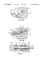
- FIG. 1is an exploded view of a prosthetic attachment locking assembly according to the invention
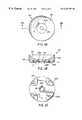
- FIGS. 2A, 2 B and 2 Care respectively top, sectional and bottom views of a distal adapter according to the invention, in which the sectional view of FIG. 2B is taken along line B—B of FIG. 2A;
- FIGS. 3A and 3Bare respectively top and sectional views of a prosthetic attachment lock according to the invention, in which the sectional view of FIG. 3B is taken along line III-III of FIG. 1;
- FIG. 4is a detail showing a locking device according to the invention.
- FIG. 5is a top view of a prosthetic attachment lock according to another embodiment of the invention.
- a prosthetic attachment locking assemblyis composed of a distal adapter 10 and a prosthetic attachment lock 20 .
- the distal adapter 10shown in greater detail in FIGS. 2A-2C, is preferably formed of machined aluminum although other rigid materials having the requisite characteristics may be used. It is generally formed as a roughly cylindrically body having a part-spherical concave upper surface 22 and a generally planar lower surface 24 .
- a central pin bore 26extends through the body of the distal adapter 10 from the upper surface 22 to the lower surface 24 .
- the upper part of the pin bore 26is in the form of a conical outward taper 26 a which merges with the upper surface 22 , while the lower end of the pin bore 26 is extended downwardly by an annular rim 26 b.
- a number (four in this embodiment) of projections 24 aextend integrally downward from the bottom surface 24 , adjacent the periphery of the bottom surface and by the same distance as the rim 26 b .
- the projections 24 aform flat bottom surfaces into which threaded screw holes 24 b are bored.
- An air expulsion hole 27extends through the body of the distal adapter from the top surface 22 to the bottom surface 24 .
- a series of annular grooves 29 in the peripheral cylindrical surface of the distal adaptercan hold sealing rings such as O-rings 29 a , for the purpose described below.
- the distal adapter 10is sealingly fitted into the bottom of a rigid socket 40 .
- the sealing at the periphery of the distal adaptor 10is assured by the sealing rings 29 a .
- the socketmay generally be of a conventional design except as noted below, and may be formed of a thermoplastic material or a carbon fiber laminate, although it may instead be formed of other materials which can satisfy the functional requirements of a prosthetic socket.
- the socket 40has an internal surface 42 whose shape can cooperate with a residual limb stump so that the stump can comfortably fit within the socket and form an air tight seal.
- the distal adapter 10may be fitted within the bottom of the socket 40 in a variety of ways, including press fitting the distal adaptor into the already formed socket, or by the socket being molded or laid up (laminated) around the distal adapter 10 .
- the internal configuration of the inner surface 42 of the socket wallshould be such that it forms a smooth or seamless transition to the edge of the top surface 22 of the distal adapter so that the end of the lock pin 60 of the prosthetic attachment locking assembly will not catch on a lip, and can smoothly be guided to the top surface 22 and the pin bore 26 .
- This seamless mergingcan be accomplished by providing that the inner surface 42 of the wall of the socket, in its portion 44 located at and immediately above the edge of the top wall 22 of the distal adapter 10 , has substantially the same radius and center as the part-spherical top surface 22 .
- the radius of the top surface 22is preferably 0.3 to 5 inches, more preferably 1.5 to 2 inches, and the outside diameter of the distal adapter 10 is preferably 1 to 3 inches.
- the rim 26 b and the projections 24 aextend through the wall of the bottom of the socket 40 and provide flat external surfaces coplanar with the bottom exterior surface 46 of this bottom wall.
- the projections 24 atherefore provide surfaces integral with the distal adapter for secure and stable attachment of the prosthetic attachment lock 20 , and the rim 26 b provides a seal against air leakage from the joint between the air expulsion hole 27 and a colinear air hole 48 in the bottom of the socket 40 .
- the prosthetic attachment lock 20has a lock body 20 A which may be in the form of a flat disk with a generally rectangular shape (although in the illustrated embodiment the lock body is not precisely rectangular). It may be made of machined aluminum or another rigid material which is adaptable to the same purpose.
- the lock body 20 Amay have planar upper and lower surfaces 20 A a and 20 A b , and a pin bore 28 extending therethrough from the upper surface 20 A a to the lower surface 20 A b .
- Through holes 30are also provided at positions which may be aligned with the threaded screw holes 24 b in the projections 24 a of the distal adapter 10 .
- the lock body 20 Aalso has an air valve hole 32 which can hold a one way air valve 32 c , e.g., an elastomeric “duck bill,” and which has outlet 32 a or 32 b .
- the air valve holeis aligned with, and communicates with, the air expulsion holes 27 and 48 for expelling to the outside the air which is displaced by the insertion of the residual stump into the socket.
- the one way valve 32 ccloses to maintain the suction once the stump is inserted.
- the one way valve 32 cis shown in its preferred location in the prosthetic attachment lock 20 , it can be located in another part of the prosthetic attachment lock. Also, a muffler 110 , as illustrated in FIG. 5, made of micro-cellular foam or another suitable material may be provided at one of the outlets 32 a or 32 b . A filter (not shown) may be positioned at the valve so as to keep contaminants from the socket from reaching the valve.
- the lock pin 60may be mounted, e.g., by molding or screwing, to a rigid urethane body 62 secured or formed at the lower end of the stump liner 64 .
- the body 62has a dome-like lower surface which can mate with the upper surface 22 of the distal adapter 10 .
- the lock pinhas a series of tooth-like serrations and may be conventional, except that it further includes an annular sealing element 66 formed of rubber or some other elastomeric material and shaped to form an air tight seal with the conical taper 26 a of the distal adapter when the lock pin 60 is locked into the prosthetic attachment lock.
- a cylindrical bore 36 for housing the locking deviceis formed in the lock body 20 A and extends from one of the side surfaces into the lock body such that it intersects the pin bore 28 . It is extended by a smaller diameter centering the hole 38 which cooperates with the locking device as set forth below.
- the locking device 80which is best seen in FIG. 4, has a centering axle 82 which is extended by a pin 84 which is guided for longitudinal and rotational motion by the centering bore 38 of the lock body 20 A acting as a bearing for the pin 84 .
- a locking gear 86is fixedly mounted on the centering axle and can be located within the bore 36 such that its teeth extend into the pin bore 28 and mesh with the serrations of the lock pin 60 when the lock pin 60 extends into the pin bore 28 .
- movement of the lock pin 60 into the pin bore 28will cause rotation of the locking gear 86 and the centering axle 82 , but removal of the lock pin 60 is prevented by the one-way clutch (described below) which prevents opposite rotation of the locking gear 86 .
- the above described locking deviceis conventional, except for the features of the one-way clutch set forth below.
- the centering axle 82is slidably mounted for movement along its length within the bore of a load bearing sleeve 88 , which bore forms a linear bearing for the centering axle 82 .
- a dowel 90which extends through a bore in a flange 92 of the sleeve 88 , and also extends through an elongated slot 94 of the centering axle 82 .
- the load bearing sleeve 88cooperates with an outer sleeve 96 and clutch elements 98 of a one-way rotation clutch.
- a conventional clutch usable for this purposemay be the Stock Drive Products roller clutch model S99NH3MURC1012.
- the outer sleeve 96 of the clutchmay be fixed by press fitting within the bore 36 .
- the load bearing sleeve 88is permitted by the one-way clutch to rotate in one direction within the bore 36 .
- the centering axle 82 and the locking gear 86rotate with the sleeve 88 due to the dowel 90 extending through the slot 94 .
- the length of the slot 94is such as to permit the centering axle to move longitudinally within the sleeve 88 until the gear 86 disengages from a lock pin 60 in the pin bore 28 .
- a push button 100is attached to an end of the centering axle and extends out of the lock body 20 A.
- the locking gear 86then disengages from the lock pin 60 which can be removed from the lock body 20 A without impediment.
- the linear bearing support of the centering axle 82 within the bore of the sleeve 88comprises an example of disengaging means for permitting the gear to disengage from said lock pin.
- the one-way clutch 96 - 98 held in place by sleeve 88 and retaining ring 89comprises an example of means for permitting only one way rotation of the gear 86 .
- This one-way clutchis independent of the disengaging means since clutch elements do not engage with the centering axle 82 or the inner bore of the sleeve 88 .
- the distal adapteris typically attached to a model of the user's stump.
- the thermoplasticis formed over the distal adapter 10 and the model of the stump.
- the thermoplastic on the distal end of the socketis then removed or reshaped until the projections 24 a are exposed so that the prosthetic attachment lock 20 and the prosthetic limb 50 can be attached.
- the reinforcing fiberis positioned across the sides of the socket and across the bottom surface 24 of the distal adaptor 10 between the projections 24 a .
- a flat laminating plateis then attached to the projections 24 a , and the laminating resin is formed over the model of the stump and the distal adaptor.
- the flat laminating plateis then removed, leaving a flat surface for attaching the prosthetic attachment lock 20 and the prosthetic limb 50 .
- the amputeeapplies the stump liner to the residual limb stump such that the lock pin 60 is located at the end of the stump.
- the userthen steps into, or pulls on, the socket 40 .
- the end of the lock pinwhich may initially bear against the inner surface 42 , smoothly moves from engagement with the inner surface 42 of the socket to engagement with the part-spherical top surface 22 of the distal adapter due to the surface radius at 44 .
- the part-spherical surface 22guides the lock pin 60 toward the pin bore 26 .
- the lock pinfits into, and extends through, the pin bore 26 of the distal adapter and through the pin bore 28 of the lock body 20 A.
- the lock gear 86rotates to permit the lock pin 60 to pass through the pin bore 28 , but the one-way clutch prevents its removal. Simultaneously, an air tight seal is formed between the residual stump and the inner surface 42 of the socket, causing air to be expelled through the air holes 27 and 48 , and through the one way valve 32 c .
- the one way valvemoreover, prevents air return so as to assure a suction lock.
- the usercan then rotate the button 100 so as to rotate the gear 86 , thereby further and securely locking the lock pin 60 in the pin bore 28 .
- a slot at the end of the push buttonwill accept a coin or the head of a screwdriver to assist in locking down the lock pin. This presses the body 62 onto the upper surface 22 and compresses the seal material 66 to prevent air leakage past the pin bore 26 . It also creates an upward reaction load on the lock pin 60 , which is transferred to the one-way clutch.
- the userpushes the button 100 in the direction A. Since the turning load applied onto the gear 86 by the reaction load on the lock pin 60 is resisted by a one-way clutch which is defined between the sleeves 88 and 96 , and which is not incorporated into the centering axle 82 , the centering axle 82 can readily move independent of this load and can easily slide in response to the pressure on the button 100 to release the lock pin 60 .
Landscapes
- Health & Medical Sciences (AREA)
- Cardiology (AREA)
- Oral & Maxillofacial Surgery (AREA)
- Transplantation (AREA)
- Engineering & Computer Science (AREA)
- Biomedical Technology (AREA)
- Heart & Thoracic Surgery (AREA)
- Vascular Medicine (AREA)
- Life Sciences & Earth Sciences (AREA)
- Animal Behavior & Ethology (AREA)
- General Health & Medical Sciences (AREA)
- Public Health (AREA)
- Veterinary Medicine (AREA)
- Prostheses (AREA)
Abstract
Description
Claims (6)
Priority Applications (2)
| Application Number | Priority Date | Filing Date | Title |
|---|---|---|---|
| US09/357,855US6267787B1 (en) | 1999-07-21 | 1999-07-21 | Prosthetic attachment locking assembly having prosthetic attachment lock |
| US09/769,399US6605118B2 (en) | 1999-07-21 | 2001-01-26 | Prosthetic attachment locking assembly having prosthetic attachment lock |
Applications Claiming Priority (1)
| Application Number | Priority Date | Filing Date | Title |
|---|---|---|---|
| US09/357,855US6267787B1 (en) | 1999-07-21 | 1999-07-21 | Prosthetic attachment locking assembly having prosthetic attachment lock |
Related Child Applications (1)
| Application Number | Title | Priority Date | Filing Date |
|---|---|---|---|
| US09/769,399DivisionUS6605118B2 (en) | 1999-07-21 | 2001-01-26 | Prosthetic attachment locking assembly having prosthetic attachment lock |
Publications (1)
| Publication Number | Publication Date |
|---|---|
| US6267787B1true US6267787B1 (en) | 2001-07-31 |
Family
ID=23407317
Family Applications (2)
| Application Number | Title | Priority Date | Filing Date |
|---|---|---|---|
| US09/357,855Expired - LifetimeUS6267787B1 (en) | 1999-07-21 | 1999-07-21 | Prosthetic attachment locking assembly having prosthetic attachment lock |
| US09/769,399Expired - LifetimeUS6605118B2 (en) | 1999-07-21 | 2001-01-26 | Prosthetic attachment locking assembly having prosthetic attachment lock |
Family Applications After (1)
| Application Number | Title | Priority Date | Filing Date |
|---|---|---|---|
| US09/769,399Expired - LifetimeUS6605118B2 (en) | 1999-07-21 | 2001-01-26 | Prosthetic attachment locking assembly having prosthetic attachment lock |
Country Status (1)
| Country | Link |
|---|---|
| US (2) | US6267787B1 (en) |
Cited By (26)
| Publication number | Priority date | Publication date | Assignee | Title |
|---|---|---|---|---|
| WO2002028324A1 (en)* | 2000-10-04 | 2002-04-11 | Ossur Hf | Prosthetic socket and socket component assembly |
| USD462768S1 (en) | 2001-10-01 | 2002-09-10 | Bulldog Tools Inc. | Slidable and rotatable coupler for a prosthetic leg |
| USD462767S1 (en) | 2001-10-01 | 2002-09-10 | Bulldog Tools Inc. | Slidable and rotatable coupler for a prosthetic leg |
| US6605118B2 (en)* | 1999-07-21 | 2003-08-12 | Ohio Willow Wood Company | Prosthetic attachment locking assembly having prosthetic attachment lock |
| WO2003034904A3 (en)* | 2001-10-25 | 2003-10-30 | Douglas A Taylor | Socket preform/adapter combination for prosthetic device and method of manufacture |
| US20040030410A1 (en)* | 2002-05-03 | 2004-02-12 | Wagman Chris L. | Prosthetic attachment locking device |
| US6797008B1 (en) | 2001-10-22 | 2004-09-28 | Ohio Willow Wood | System and method for securing a prosthetic limb |
| US20040260402A1 (en)* | 2003-06-20 | 2004-12-23 | Baldini Steven E. | Method of manufacturing a socket portion of a prosthetic limb |
| US20050038522A1 (en)* | 2003-08-15 | 2005-02-17 | Helenberger Derek M. | Prosthetic angled locking coupler device |
| US20050216096A1 (en)* | 2004-03-26 | 2005-09-29 | Wagman Chris L | Prosthetic attachment locking device with dual locking mechanism |
| EP1637097A3 (en)* | 2004-09-08 | 2006-03-29 | Otto Bock HealthCare IP GmbH & Co. KG | One way clutch and its use in prostheses |
| WO2006076011A1 (en)* | 2004-04-30 | 2006-07-20 | Ossur Hf | Prosthesis locking assembly |
| US20070168045A1 (en)* | 2006-01-05 | 2007-07-19 | Slemker Tracy C | Double-wall prosthetic limb assembly |
| US20080234836A1 (en)* | 2004-06-21 | 2008-09-25 | Douglas Taylor | Socket preform/adapter combination for prosthetic device and method of manufacture |
| US20110071648A1 (en)* | 2009-09-18 | 2011-03-24 | Mckinney Donald Ray | Prosthetic socket |
| US7927377B2 (en) | 2008-06-09 | 2011-04-19 | Prosthetic Design, Inc. | Elevated vacuum locking system |
| US20110144756A1 (en)* | 2009-10-10 | 2011-06-16 | Bickley Barry T | Method and apparatus for restoring a joint, including the provision and use of a longitudinally-adjustable and rotationally-adjustable joint prosthesis |
| US8470050B2 (en) | 2011-04-08 | 2013-06-25 | Timothy R. Dillingham | Rapid fit modular prosthetic device for accommodating gait alignment and residual limb shape and volume |
| US8491667B2 (en) | 2011-04-08 | 2013-07-23 | Timothy R Dillingham | Modular prosthesis system |
| US8845755B2 (en) | 2011-04-08 | 2014-09-30 | Ifit Prosthetics, Llc | Modular prosthetic devices and prosthesis system |
| US20190125553A1 (en)* | 2017-11-01 | 2019-05-02 | Ossur Iceland Ehf | Prosthetic socket system |
| US10398577B2 (en) | 2011-04-08 | 2019-09-03 | Ifit Prosthetics, Llc | Modular prosthetic devices and prosthesis systems |
| US10806608B2 (en) | 2011-04-08 | 2020-10-20 | Ifit Prosthetics, Llc | Prosthetic method and apparatus |
| US11185430B2 (en) | 2019-01-10 | 2021-11-30 | Ossur Iceland Ehf | Prosthetic attachment system and corresponding lock assembly |
| US11382775B2 (en) | 2011-04-08 | 2022-07-12 | Ifit Prosthetics, Llc | Modular prosthetic devices and prosthesis systems |
| US11642233B2 (en) | 2020-09-04 | 2023-05-09 | Ossur Iceland Ehf | Interchangeable distal end for a prosthetic socket system |
Families Citing this family (14)
| Publication number | Priority date | Publication date | Assignee | Title |
|---|---|---|---|---|
| GB2411841B (en)* | 2004-03-12 | 2006-08-09 | Univ London | Prosthetic limb attachment |
| WO2006138388A2 (en)* | 2005-06-17 | 2006-12-28 | Ada Technologies, Inc. | Cable lock device for prosthetic and orthotic devices |
| US7955397B2 (en)* | 2006-07-03 | 2011-06-07 | Biomotions, Llc | Socket and sleeve for attachment to a residual limb |
| US20080188952A1 (en)* | 2007-02-05 | 2008-08-07 | Ada Technologies, Inc. | Pre-positionable prosthetic hand |
| US10842653B2 (en) | 2007-09-19 | 2020-11-24 | Ability Dynamics, Llc | Vacuum system for a prosthetic foot |
| US8052761B2 (en) | 2008-05-15 | 2011-11-08 | Invisible Hand Enterprises, Llc | Prosthetic split hook terminal device with adjustable pinch force, functional grasping contours and illumination |
| US8533930B2 (en)* | 2008-09-05 | 2013-09-17 | Ati Industrial Automation, Inc. | Manual robotic tool changer having rapid coupling mechanism |
| WO2010039925A1 (en)* | 2008-10-01 | 2010-04-08 | Ada Technologies, Inc. | Anatomically-configured adjustable upper extremity prosthetic device |
| US8113235B2 (en)* | 2008-10-03 | 2012-02-14 | David Robert Bogue | Apparatus and methods for facilitating prosthesis donning, doffing, retention, and fit |
| US10238511B1 (en) | 2011-08-12 | 2019-03-26 | Kaione R. Newton | Electromagnetic suspension system for prosthetic device |
| WO2015002955A1 (en) | 2013-07-03 | 2015-01-08 | Ossur Hf | Prosthetic pin locking mechanism with vacuum tunnels |
| US12150870B2 (en)* | 2016-02-02 | 2024-11-26 | Hanger, Inc. | Orthotic and prosthetic device and manufacturing system and method |
| US11224527B2 (en)* | 2018-01-30 | 2022-01-18 | Alps South Europe, S.R.O. | Interchangeable pump-lock for prosthetic socket and method of use |
| EP4551165A1 (en)* | 2022-07-29 | 2025-05-14 | Alps South, LLC | Prosthetic liner with external elastomeric seal |
Citations (3)
| Publication number | Priority date | Publication date | Assignee | Title |
|---|---|---|---|---|
| US5226918A (en)* | 1992-07-13 | 1993-07-13 | Howard Silagy | Prosthesis with adjustable fitting clearance |
| US5702489A (en)* | 1995-08-18 | 1997-12-30 | Materials Engineering And Development, Inc. | Valve assembly for a prosthetic limb |
| US5888234A (en)* | 1997-07-16 | 1999-03-30 | United States Manufacturing Company | Shuttle lock |
Family Cites Families (6)
| Publication number | Priority date | Publication date | Assignee | Title |
|---|---|---|---|---|
| US980457A (en)* | 1910-01-13 | 1911-01-03 | Justin Kay Toles | Artificial limb. |
| US5163965A (en)* | 1991-07-29 | 1992-11-17 | Becker Orthopedic Appliance Company | Prosthetic attachment device and method |
| US6287345B1 (en)* | 1995-08-18 | 2001-09-11 | The Ohio Willow Wood Company | Valve assembly for a prosthetic limb |
| EP0765646B1 (en)* | 1995-09-08 | 2000-12-06 | Otto Bock Orthopädische Industrie Besitz- und Verwaltungs-Kommanditgesellschaft | Lower leg prosthesis |
| US6334876B1 (en)* | 1998-05-05 | 2002-01-01 | Dale Perkins | Safety suction valve |
| US6267787B1 (en)* | 1999-07-21 | 2001-07-31 | Ohio Willow Wood Company | Prosthetic attachment locking assembly having prosthetic attachment lock |
- 1999
- 1999-07-21USUS09/357,855patent/US6267787B1/ennot_activeExpired - Lifetime
- 2001
- 2001-01-26USUS09/769,399patent/US6605118B2/ennot_activeExpired - Lifetime
Patent Citations (3)
| Publication number | Priority date | Publication date | Assignee | Title |
|---|---|---|---|---|
| US5226918A (en)* | 1992-07-13 | 1993-07-13 | Howard Silagy | Prosthesis with adjustable fitting clearance |
| US5702489A (en)* | 1995-08-18 | 1997-12-30 | Materials Engineering And Development, Inc. | Valve assembly for a prosthetic limb |
| US5888234A (en)* | 1997-07-16 | 1999-03-30 | United States Manufacturing Company | Shuttle lock |
Cited By (42)
| Publication number | Priority date | Publication date | Assignee | Title |
|---|---|---|---|---|
| US6605118B2 (en)* | 1999-07-21 | 2003-08-12 | Ohio Willow Wood Company | Prosthetic attachment locking assembly having prosthetic attachment lock |
| US6589289B2 (en)* | 2000-10-04 | 2003-07-08 | Ossur Hf | Prosthetic socket and socket component assembly |
| WO2002028324A1 (en)* | 2000-10-04 | 2002-04-11 | Ossur Hf | Prosthetic socket and socket component assembly |
| USD462768S1 (en) | 2001-10-01 | 2002-09-10 | Bulldog Tools Inc. | Slidable and rotatable coupler for a prosthetic leg |
| USD462767S1 (en) | 2001-10-01 | 2002-09-10 | Bulldog Tools Inc. | Slidable and rotatable coupler for a prosthetic leg |
| US6797008B1 (en) | 2001-10-22 | 2004-09-28 | Ohio Willow Wood | System and method for securing a prosthetic limb |
| WO2003034904A3 (en)* | 2001-10-25 | 2003-10-30 | Douglas A Taylor | Socket preform/adapter combination for prosthetic device and method of manufacture |
| US20040030410A1 (en)* | 2002-05-03 | 2004-02-12 | Wagman Chris L. | Prosthetic attachment locking device |
| US6979354B2 (en)* | 2002-05-03 | 2005-12-27 | Wagman Manufacturing, Inc. | Prosthetic attachment locking device |
| US20040260402A1 (en)* | 2003-06-20 | 2004-12-23 | Baldini Steven E. | Method of manufacturing a socket portion of a prosthetic limb |
| US7083654B2 (en)* | 2003-08-15 | 2006-08-01 | Becker Orthopedic Appliance Company | Prosthetic angled locking coupler device |
| US20050038522A1 (en)* | 2003-08-15 | 2005-02-17 | Helenberger Derek M. | Prosthetic angled locking coupler device |
| US20050216096A1 (en)* | 2004-03-26 | 2005-09-29 | Wagman Chris L | Prosthetic attachment locking device with dual locking mechanism |
| US7108722B2 (en) | 2004-03-26 | 2006-09-19 | Wagman Manufacturing, Inc. | Prosthetic attachment locking device with dual locking mechanism |
| WO2006076011A1 (en)* | 2004-04-30 | 2006-07-20 | Ossur Hf | Prosthesis locking assembly |
| US7217060B2 (en) | 2004-04-30 | 2007-05-15 | Ossur Hf | Prosthesis locking assembly |
| US20080234836A1 (en)* | 2004-06-21 | 2008-09-25 | Douglas Taylor | Socket preform/adapter combination for prosthetic device and method of manufacture |
| EP1637097A3 (en)* | 2004-09-08 | 2006-03-29 | Otto Bock HealthCare IP GmbH & Co. KG | One way clutch and its use in prostheses |
| US7429271B2 (en) | 2004-09-08 | 2008-09-30 | Otto Bock Heathcare Ip Gmbh & Co., Kg | Clamping freewheel and its use for a prosthetic part |
| CN1793681B (en)* | 2004-09-08 | 2011-05-25 | 奥托·博克保健有限公司 | Clamping freewheel mechanism and application to a prosthetic component |
| US20070168045A1 (en)* | 2006-01-05 | 2007-07-19 | Slemker Tracy C | Double-wall prosthetic limb assembly |
| US8097042B2 (en)* | 2006-01-05 | 2012-01-17 | Prosthetic Design, Inc. | Double-wall prosthetic limb assembly |
| US7927377B2 (en) | 2008-06-09 | 2011-04-19 | Prosthetic Design, Inc. | Elevated vacuum locking system |
| US20110071648A1 (en)* | 2009-09-18 | 2011-03-24 | Mckinney Donald Ray | Prosthetic socket |
| US8282686B2 (en)* | 2009-09-18 | 2012-10-09 | Lincolnshire Manufacturing LLC | Prosthetic socket |
| US8623092B2 (en)* | 2009-10-10 | 2014-01-07 | Simplicity Orthopedics, Inc. | Method and apparatus for restoring a joint, including the provision and use of a longitudinally-adjustable and rotationally-adjustable joint prosthesis |
| US20140324185A1 (en)* | 2009-10-10 | 2014-10-30 | Simplicity Orthopedics, Inc. | Method and apparatus for restoring a joint, including the provision and use of a longitudinally-adjustable and rotationally-adjustable joint prosthesis |
| US9474618B2 (en)* | 2009-10-10 | 2016-10-25 | Simplicity Orthopedics, Inc. | Method and apparatus for restoring a joint, including the provision and use of a longitudinally-adjustable and rotationally-adjustable joint prosthesis |
| US20110144756A1 (en)* | 2009-10-10 | 2011-06-16 | Bickley Barry T | Method and apparatus for restoring a joint, including the provision and use of a longitudinally-adjustable and rotationally-adjustable joint prosthesis |
| US11382775B2 (en) | 2011-04-08 | 2022-07-12 | Ifit Prosthetics, Llc | Modular prosthetic devices and prosthesis systems |
| US8470050B2 (en) | 2011-04-08 | 2013-06-25 | Timothy R. Dillingham | Rapid fit modular prosthetic device for accommodating gait alignment and residual limb shape and volume |
| US8491667B2 (en) | 2011-04-08 | 2013-07-23 | Timothy R Dillingham | Modular prosthesis system |
| US8845755B2 (en) | 2011-04-08 | 2014-09-30 | Ifit Prosthetics, Llc | Modular prosthetic devices and prosthesis system |
| US10398577B2 (en) | 2011-04-08 | 2019-09-03 | Ifit Prosthetics, Llc | Modular prosthetic devices and prosthesis systems |
| US10806608B2 (en) | 2011-04-08 | 2020-10-20 | Ifit Prosthetics, Llc | Prosthetic method and apparatus |
| US20190125553A1 (en)* | 2017-11-01 | 2019-05-02 | Ossur Iceland Ehf | Prosthetic socket system |
| US10945865B2 (en)* | 2017-11-01 | 2021-03-16 | Ossur Iceland Ehf | Prosthetic socket sealing system |
| US11793657B2 (en) | 2017-11-01 | 2023-10-24 | Ossur Iceland Ehf | Prosthetic socket system |
| US11185430B2 (en) | 2019-01-10 | 2021-11-30 | Ossur Iceland Ehf | Prosthetic attachment system and corresponding lock assembly |
| US11911299B2 (en) | 2019-01-10 | 2024-02-27 | Ossur Iceland Ehf | Prosthetic attachment system and corresponding lock assembly |
| US11642233B2 (en) | 2020-09-04 | 2023-05-09 | Ossur Iceland Ehf | Interchangeable distal end for a prosthetic socket system |
| US12150869B2 (en) | 2020-09-04 | 2024-11-26 | Ossur Iceland Ehf | Interchangeable distal end for a prosthetic socket system |
Also Published As
| Publication number | Publication date |
|---|---|
| US6605118B2 (en) | 2003-08-12 |
| US20010001837A1 (en) | 2001-05-24 |
Similar Documents
| Publication | Publication Date | Title |
|---|---|---|
| US6267787B1 (en) | Prosthetic attachment locking assembly having prosthetic attachment lock | |
| US7217060B2 (en) | Prosthesis locking assembly | |
| US6689171B2 (en) | Shuttle lock | |
| US20200188141A1 (en) | Prosthetic liner and prosthetic shaft system comprising prosthetic liner and prosthetic shaft | |
| JP2004510495A (en) | Prosthetic socket and socket component assembly | |
| US5100272A (en) | Device providing detachable assembly | |
| US5026010A (en) | Latched detachable leg assembly | |
| US20060079965A1 (en) | Quick-release tube clamp for modular lower limb prosthetic systems and method therefor | |
| KR101246543B1 (en) | Hydraulic hand tool | |
| KR100716560B1 (en) | Structure for joining outer cover and inner cover of manhole | |
| US20110022184A1 (en) | Sealing liner and lock for prosthetic limb | |
| BR0313766A (en) | Reinforced textile hose fitting and hose assembly | |
| CA2059436A1 (en) | Non-impact keyless tool chuck sleeve | |
| US20040204771A1 (en) | Adapter bracket for prostheses, method and apparatus for forming prosthetic device with transfer of proper alignment | |
| US6589288B2 (en) | Adjustable plunger pin assembly for a prosthetic limb | |
| CA2720656A1 (en) | Limb stump receiving sleeve comprising an integrated locking device for a sealing element | |
| GB2186641A (en) | A seal | |
| CN107352369B (en) | Door stopper for elevator landing door | |
| JPS6116411Y2 (en) | ||
| EP0015671A1 (en) | Tyre valve | |
| EP0474841A1 (en) | Artificial limb component. | |
| JPS6017590Y2 (en) | Disengagement prevention pipe fitting | |
| JPS6018717Y2 (en) | Disengagement prevention pipe fitting | |
| JP2579514Y2 (en) | Dust intrusion prevention mechanism in coupler | |
| JPH0814467A (en) | Connecting joint for mounting pipe |
Legal Events
| Date | Code | Title | Description |
|---|---|---|---|
| AS | Assignment | Owner name:OHIO WILLOW WOOD COMPANY, OHIO Free format text:ASSIGNMENT OF ASSIGNORS INTEREST;ASSIGNORS:CAPPER, JAMES W.;ARBOGAST, ROBERT E.;DODDROE, JEFFREY L.;AND OTHERS;REEL/FRAME:010203/0056 Effective date:19990805 | |
| STCF | Information on status: patent grant | Free format text:PATENTED CASE | |
| FEPP | Fee payment procedure | Free format text:PAYER NUMBER DE-ASSIGNED (ORIGINAL EVENT CODE: RMPN); ENTITY STATUS OF PATENT OWNER: SMALL ENTITY Free format text:PAYOR NUMBER ASSIGNED (ORIGINAL EVENT CODE: ASPN); ENTITY STATUS OF PATENT OWNER: SMALL ENTITY | |
| FEPP | Fee payment procedure | Free format text:PAT HOLDER CLAIMS SMALL ENTITY STATUS, ENTITY STATUS SET TO SMALL (ORIGINAL EVENT CODE: LTOS); ENTITY STATUS OF PATENT OWNER: SMALL ENTITY | |
| FPAY | Fee payment | Year of fee payment:4 | |
| FPAY | Fee payment | Year of fee payment:8 | |
| REMI | Maintenance fee reminder mailed | ||
| FPAY | Fee payment | Year of fee payment:12 | |
| SULP | Surcharge for late payment | Year of fee payment:11 | |
| AS | Assignment | Owner name:WILLOWWOOD GLOBAL LLC, OHIO Free format text:ASSIGNMENT OF ASSIGNORS INTEREST;ASSIGNOR:THE OHIO WILLOW WOOD COMPANY;REEL/FRAME:049352/0264 Effective date:20190601 | |
| AS | Assignment | Owner name:MADISON CAPITAL FUNDING LLC, AS AGENT, ILLINOIS Free format text:SECURITY INTEREST;ASSIGNOR:WILLOWWOOD GLOBAL LLC;REEL/FRAME:049376/0071 Effective date:20190605 | |
| AS | Assignment | Owner name:WILLOWWOOD GLOBAL LLC, OHIO Free format text:RELEASE BY SECURED PARTY;ASSIGNOR:MADISON CAPITAL FUNDING LLC, AS AGENT;REEL/FRAME:058786/0492 Effective date:20211202 |