US6267757B1 - Revascularization with RF ablation - Google Patents
Revascularization with RF ablationDownload PDFInfo
- Publication number
- US6267757B1 US6267757B1US08/942,874US94287497AUS6267757B1US 6267757 B1US6267757 B1US 6267757B1US 94287497 AUS94287497 AUS 94287497AUS 6267757 B1US6267757 B1US 6267757B1
- Authority
- US
- United States
- Prior art keywords
- energy
- patient
- distal tip
- heart
- elongated
- Prior art date
- Legal status (The legal status is an assumption and is not a legal conclusion. Google has not performed a legal analysis and makes no representation as to the accuracy of the status listed.)
- Expired - Fee Related, expires
Links
- 230000000250revascularizationEffects0.000titleabstractdescription7
- 238000007674radiofrequency ablationMethods0.000titledescription9
- 238000000034methodMethods0.000claimsdescription31
- 239000004020conductorSubstances0.000claimsdescription4
- 230000000541pulsatile effectEffects0.000claimsdescription3
- 210000005166vasculatureAnatomy0.000claimsdescription3
- 238000002679ablationMethods0.000claimsdescription2
- 210000005003heart tissueAnatomy0.000abstractdescription3
- 230000002107myocardial effectEffects0.000abstract1
- 210000001519tissueAnatomy0.000description9
- 239000007787solidSubstances0.000description7
- 235000014676Phragmites communisNutrition0.000description4
- 210000000038chestAnatomy0.000description4
- 210000001174endocardiumAnatomy0.000description4
- 210000005240left ventricleAnatomy0.000description4
- 230000008901benefitEffects0.000description2
- 210000005242cardiac chamberAnatomy0.000description2
- 238000002324minimally invasive surgeryMethods0.000description2
- 239000013307optical fiberSubstances0.000description2
- 238000001356surgical procedureMethods0.000description2
- 210000000115thoracic cavityAnatomy0.000description2
- 210000000779thoracic wallAnatomy0.000description2
- 238000002399angioplastyMethods0.000description1
- 210000000709aortaAnatomy0.000description1
- 230000009286beneficial effectEffects0.000description1
- 230000015572biosynthetic processEffects0.000description1
- 239000000032diagnostic agentSubstances0.000description1
- 229940039227diagnostic agentDrugs0.000description1
- 239000003814drugSubstances0.000description1
- 210000001105femoral arteryAnatomy0.000description1
- 238000002682general surgeryMethods0.000description1
- 230000002452interceptive effectEffects0.000description1
- 239000000463materialSubstances0.000description1
- 230000002093peripheral effectEffects0.000description1
- 239000004065semiconductorSubstances0.000description1
- 229940124597therapeutic agentDrugs0.000description1
- 230000001225therapeutic effectEffects0.000description1
- 230000002861ventricularEffects0.000description1
Images


Classifications
- A—HUMAN NECESSITIES
- A61—MEDICAL OR VETERINARY SCIENCE; HYGIENE
- A61B—DIAGNOSIS; SURGERY; IDENTIFICATION
- A61B18/00—Surgical instruments, devices or methods for transferring non-mechanical forms of energy to or from the body
- A61B18/04—Surgical instruments, devices or methods for transferring non-mechanical forms of energy to or from the body by heating
- A61B18/12—Surgical instruments, devices or methods for transferring non-mechanical forms of energy to or from the body by heating by passing a current through the tissue to be heated, e.g. high-frequency current
- A61B18/14—Probes or electrodes therefor
- A61B18/1492—Probes or electrodes therefor having a flexible, catheter-like structure, e.g. for heart ablation
- A—HUMAN NECESSITIES
- A61—MEDICAL OR VETERINARY SCIENCE; HYGIENE
- A61B—DIAGNOSIS; SURGERY; IDENTIFICATION
- A61B18/00—Surgical instruments, devices or methods for transferring non-mechanical forms of energy to or from the body
- A61B2018/00315—Surgical instruments, devices or methods for transferring non-mechanical forms of energy to or from the body for treatment of particular body parts
- A61B2018/00345—Vascular system
- A61B2018/00351—Heart
- A61B2018/00392—Transmyocardial revascularisation
- A—HUMAN NECESSITIES
- A61—MEDICAL OR VETERINARY SCIENCE; HYGIENE
- A61B—DIAGNOSIS; SURGERY; IDENTIFICATION
- A61B18/00—Surgical instruments, devices or methods for transferring non-mechanical forms of energy to or from the body
- A61B2018/00636—Sensing and controlling the application of energy
- A61B2018/00696—Controlled or regulated parameters
- A61B2018/00738—Depth, e.g. depth of ablation
- A—HUMAN NECESSITIES
- A61—MEDICAL OR VETERINARY SCIENCE; HYGIENE
- A61B—DIAGNOSIS; SURGERY; IDENTIFICATION
- A61B18/00—Surgical instruments, devices or methods for transferring non-mechanical forms of energy to or from the body
- A61B2018/00636—Sensing and controlling the application of energy
- A61B2018/00773—Sensed parameters
- A61B2018/00839—Bioelectrical parameters, e.g. ECG, EEG
Definitions
- This inventionis directed to the ablation of tissue in the wall of a patient's heart and particularly to form channels within the heart wall in order to perform transmyocardial revascularization (TMR), to deliver therapeutic or diagnostic agents to various locations in the patient's heart wall or for a variety of other utilities.
- TMRtransmyocardial revascularization
- TMRtranscranial magnetic resonance
- the first clinical trials of the TMR procedure using laser energywere performed by Mirhoseini et al. See for example the discussions in Lasers in General Surgery (Williams & Wilkins; 1989), pp 18 216-223.
- Other early disclosures of the TMR procedureare found in an article by Okada et al. in Kobe J. Med. Sci 32, 151-161, October 1986 and in U.S. Pat. No. 4,658,817 (Hardy). These early references describe intraoperative TMR procedures which require an opening in the chest wall and include formation of channels completely through the heart wall starting from the epicardium.
- the distal end of the optical fiber deviceis directed toward a desired location on the patient's endocardium and urged against the endocardial surface while a laser beam is emitted from its distal end to form the channel.
- the laser based revascularization procedurehas been shown to be clinically beneficial to a variety of patients, particularly patients who were, for the most part, not suitable candidates for by-pass surgery or for minimally invasive procedures such as angioplasty or atherectomy.
- the equipment for laser based systemshas been quite expensive. What has been needed is a system which is cheaper than but as clinically effective as laser based systems.
- the present inventionsatisfies these and other needs.
- the present inventionis directed to a method and system for the revascularization of a region of a patient's heart by ablating tissue in said region with emissions of radio frequency (RF) energy over discrete intervals and is particularly directed to the method and system to ablate tissue in the patient's heart wall to form channels therein by means of such RF energy.
- RFradio frequency
- tissueis ablated within a patient's heart wall by means of one or more bursts of RF emissions over intervals of about one to about 500 msec and preferably about 30 to about 130 msec.
- An RF burstmay comprise a continuous emission or discontinuous emission, i.e. be pulsatile, and, if pulsatile, may involve a plurality or train of pulses which may or may not be of the same width (duration), frequency or amplitude.
- the RF emissionsis preferably controlled so that heart tissue is exposed to the RF energy over a desired period and particularly over a period which will avoid interfering with the patient's heart beat, e.g. just after the R wave but before the T wave.
- One to about 10 bursts of RF energymay be required to effectively form the desired channel within the patient's heart wall and preferably one burst of RF emission is delivered per heart cycle.
- the RF energy sourcegenerally should have a peak power output of about 150 to about 500 watts, preferably about 200 to about 300 watts.
- One presently preferred system for forming the channels in the patient's heart wallincludes an RF energy transmitting member which has a proximal end, an elongated shaft insulated along a length thereof and an uninsulated distal tip configured to emit RF energy.
- the systemis introduced into the patient and advanced within the patient until the uninsulated distal tip thereof is disposed adjacent to a surface of the patient's heart wall.
- At least one burst of RF energy from an RF energy sourceis transmitted through the RF energy transmitting member to the uninsulated distal tip thereof and from which transmitted RF energy transmitted is emitted to the surface of the heart wall in contact with said distal tip.
- the channel formed in the heart wallpreferably has an aspect ratio, i.e. depth to width, of at least 1, preferably at least 2.
- One embodiment of the inventioninvolves a percutaneous approach wherein a flexible elongated RF energy delivery system is advanced through the patient's vasculature until a distal portion of the system enters a heart chamber such as the left ventricle.
- the RF energy delivery systemis advanced so that the uninsulated distal tip thereof which emits RF energy contacts the interior surface of the heart wall which defines in part the heart chamber.
- At least one burst of RF energyis emitted from the uninsulated distal tip of the system into the patient's heart wall wherein tissue is ablated, resulting in the revascularization of the heart wall region.
- Another embodiment of the inventioninvolves a minimally invasive approach where a small incision is made in the patient's chest and with or without the benefit of a trocar sheath, an elongated RF energy transmitting system is advanced into the patient's chest cavity until the uninsulated distal tip of the RF transmitting system contacts the exterior of the patient's heart.
- One or more bursts of RF energyare emitted from the uninsulated distal tip so as to ablate tissue within the patient's heart wall causing the revascularization thereof as in the previously discussed embodiment of the invention.
- a similar proceduremay be used in conjunction with an open chest procedure such as coronary by-pass surgery.
- the RF energy transmitting systempreferably includes an elongated electrical conducting shaft which is insulated along its length except for the distal tip thereof which is uninsulated and which is configured to contact the surface of the heart wall and to emit bursts of RF energy therefrom into adjacent tissue of the heart wall.
- the uninsulated distal tiphas a diameter of about 0.025 to about 0.2 inch (0.64-5.1 mm), preferably about 0.04 to about 0.08 inch (1-2 mm) and a length of about 0.1 to about 5 mm, preferably about 1.5 to about 3.5 mm.
- the distal tipmay be solid or hollow and may be relatively sharp or blunt. However, it should not be sharp enough to penetrate the tissue of the heart wall when pressed against the wall to maintain contact during the emission of RF energy bursts.
- the average power levelshould be about 50 to about 500 watts, preferably about 100 to about 300 watts.
- the frequency of the RF currentshould not be less than 100 khz and preferably is about 250 to about 500 kh
- the method and system of the inventioneffectively ablates tissue within the patient's heart wall to revascularize the ablated region and particularly can be used to form channels within the heart wall.
- FIG. 1is a schematic illustration of a system for ablating heart tissue which embodies features of the invention.
- FIG. 2is a transverse cross-section of the RF energy transmitting member system shown in FIG. 1 taken along the lines 2 - 2 .
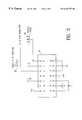
- FIG. 3is a schematic illustration of the one shot shown in FIG. 1 .
- FIG. 4is a schematic illustration of a system for generating trigger pulses based upon the patient's heart beat.
- FIG. 5is an elevational view of a delivery system for the RF ablation device for positioning the operative distal end thereof adjacent to the endocardium of a patient's heart wall.
- FIGS. 1 and 2depict an RF ablation system 10 embodying features of the invention which includes an RF energy transmitting member 11 having a proximal end configured for electrical connection to a source 12 of RF energy and an uninsulated exposed distal end 13 which is configured to emit pulsed RF energy received from the source and transmitted through the electrical conductor.
- the RF energy transmitting member 11includes an electrical conductor 14 which may be a single or multiple strand and an insulating jacket 15 formed of suitable insulating polymeric material.
- a suitable source of RF energyis the Excaliber RF Generator from Aspen Labs.
- the output from the RF energy source 12is pulsed by pulse-trigger system 16 which includes a one-shot 17 , such as CD4047 sold by National Semiconductor, configured to receive trigger pulses 18 through electrical conductor 19 and generate in response a pulsed output signal 20 connected to a NPN transistor 21 .
- the pulsed output signal 20 from the one-shot 17actuates the transistor 21 for the duration of the output signal.
- the output of the transistor 21is connected to reed relay 22 which is configured to close upon receiving the output from the transistor 21 .
- the output of the reed relay 22is connected in series to the foot switch 23 . When the foot switch 23 is closed and reed relay 22 is closed, the RF source is actuated to emit RF energy for the duration of the output of the reed relay 22 .
- FIG. 3illustrates in more detail the one-shot shown in FIG. 1 which has 14 pins, identified as pins a-n in FIG. 3 .
- the one-shot shown in FIG. 3has the pins designated with letters a-n to avoid confusion with other reference numbers used herein.
- the one-shot model number CD4047has these pins numbered 1 - 14 .
- the trigger pulse 18 from an ECG unitis received by pin h and upon receipt of the trigger pulse and an on signal is emitted from pin j.
- the duration of the on signal from pin jis controlled by the resistance R and capacitance C from the RC circuit connected to pins a-c as shown.
- the resistance Rcan typically range from about 0.1 to about 1 meg ohm and the capacitance can typically range from about 0.08 to about 0.12 microfarads to control the duration of the pulses of output signal 20 from about 50 to about 300 msec.
- FIG. 4schematically illustrates a system of generating trigger pulses 18 based upon the patient's heart cycle 30 .
- the signals from the patients heart 31are detected with a conventional ECG such as an IVY unit and detected signals are transmitted to a trigger generating system 32 which may also be contained in the IVY unit.
- the trigger pulse generating system 32is preprogrammed to emit one or more trigger pulses 18 at a predetermined time between the R and the T wave of the heart cycle 30 .
- FIG. 5illustrates a system for the percutaneous delivery of an RF ablation system which has an outer catheter 40 , a shaped distal end 41 , a port 42 in the distal end of the catheter and an inner lumen extending within the outer catheter to the port in the distal end.
- This systemalso includes an inner catheter 44 which is slidably and rotatably disposed within the inner lumen of the outer catheter 40 and which has a shaped distal section 45 , a distal end 46 , a port 47 in the distal end of the inner catheter and an inner lumen 48 extending therein to the port in the distal end.
- An RF ablation device 50is slidably disposed within the inner lumen of inner catheter 44 .
- the distal section 45 of the inner catheter 44is at an angle with respect to the main shaft section 51 of the inner catheter to orient the RF ablation device 50 extending out the distal end of the inner catheter.
- the disposition of the distal end 52 of the RF ablation device 50can be controlled by raising and lowering and rotation of the RF ablation device within the inner lumen of the inner catheter 44 and the inner catheter within the inner lumen of the outer catheter 40 .
- the distal end 52 of the RF ablation device 50is thus pointed in a desired direction to the endocardium defining the left ventricle 53 . Longitudinal and rotational movement of the inner catheter 44 provides access to a large region of the endocardium.
- Eighteen channelswere made in the heart of a live, anesthetized medium size dog by means of pulsed RF energy.
- the wattage and the size and type of distal tip of the RF delivery systemwere varied to determine the nature of the channels formed which result from such variations. The results are set forth in the table below.
Landscapes
- Health & Medical Sciences (AREA)
- Life Sciences & Earth Sciences (AREA)
- Surgery (AREA)
- Engineering & Computer Science (AREA)
- Plasma & Fusion (AREA)
- Medical Informatics (AREA)
- Otolaryngology (AREA)
- Physics & Mathematics (AREA)
- Cardiology (AREA)
- Biomedical Technology (AREA)
- Heart & Thoracic Surgery (AREA)
- Nuclear Medicine, Radiotherapy & Molecular Imaging (AREA)
- Molecular Biology (AREA)
- Animal Behavior & Ethology (AREA)
- General Health & Medical Sciences (AREA)
- Public Health (AREA)
- Veterinary Medicine (AREA)
- Surgical Instruments (AREA)
Abstract
Description
| DISTAL TIP | UNINSULATED | PULSE | NO. OF | |
| WATTAGE | TYPE | LENGTH | DURATION | PULSES |
| 200 watts | Hollow | 0.05 inch | 100 msec | 6 |
| 200 watts | Hollow | 0.05 inch | 100 msec | 5 |
| 200 watts | Hollow | 0.05 inch | 100 msec | 5 |
| 200 watts | Hollow | 0.05 inch | 100 msec | 6 |
| 200 watts | Hollow | 0.05 inch | 100 msec | 5 |
| 200 watts | Hollow | 0.05 inch | 100 msec | 5 |
| 300 watts | Hollow | 0.05 inch | 100 msec | 3 |
| 300 watts | Hollow | 0.05 inch | 100 msec | 4 |
| 300 watts | Hollow | 0.05 inch | 100 msec | 4 |
| 300 watts | Hollow | 0.05 inch | 100 msec | 5 |
| 300 watts | Hollow | 0.05 inch | 100 msec | 4 |
| 300 watts | Hollow | 0.05 inch | 100 msec | 5 |
| 300 watts | Solid | 0.15 inch | 100 msec | 4 |
| 300 watts | Solid | 0.15 inch | 100 msec | 5 |
| 300 watts | Solid | 0.15 inch | 100 msec | 6 |
| 300 watts | Solid | 0.15 inch | 100 msec | 7 |
| 300 watts | Solid | 0.15 inch | 100 msec | 5 |
| 300 watts | Solid | 0.15 inch | 100 msec | 5 |
Claims (25)
Priority Applications (7)
| Application Number | Priority Date | Filing Date | Title |
|---|---|---|---|
| US08/942,874US6267757B1 (en) | 1995-08-09 | 1997-10-02 | Revascularization with RF ablation |
| US09/107,077US6156031A (en) | 1995-08-09 | 1998-06-29 | Transmyocardial revascularization using radiofrequency energy |
| PCT/US1998/020799WO1999017671A1 (en) | 1997-10-02 | 1998-10-02 | Transmyocardial revascularization using radiofrequency energy |
| EP98950873AEP1018961A1 (en) | 1997-10-02 | 1998-10-02 | Transmyocardial revascularization using radiofrequency energy |
| JP2000514573AJP2001518345A (en) | 1997-10-02 | 1998-10-02 | Myocardial revascularization using high frequency energy |
| CA002305333ACA2305333A1 (en) | 1997-10-02 | 1998-10-02 | Transmyocardial revascularization using radiofrequency energy |
| AU96803/98AAU9680398A (en) | 1997-10-02 | 1998-10-02 | Transmyocardial revascularization using radiofrequency energy |
Applications Claiming Priority (2)
| Application Number | Priority Date | Filing Date | Title |
|---|---|---|---|
| US51749995A | 1995-08-09 | 1995-08-09 | |
| US08/942,874US6267757B1 (en) | 1995-08-09 | 1997-10-02 | Revascularization with RF ablation |
Related Parent Applications (1)
| Application Number | Title | Priority Date | Filing Date |
|---|---|---|---|
| US51749995AContinuation-In-Part | 1995-08-09 | 1995-08-09 |
Related Child Applications (1)
| Application Number | Title | Priority Date | Filing Date |
|---|---|---|---|
| US09/107,077Continuation-In-PartUS6156031A (en) | 1995-08-09 | 1998-06-29 | Transmyocardial revascularization using radiofrequency energy |
Publications (1)
| Publication Number | Publication Date |
|---|---|
| US6267757B1true US6267757B1 (en) | 2001-07-31 |
Family
ID=24060068
Family Applications (1)
| Application Number | Title | Priority Date | Filing Date |
|---|---|---|---|
| US08/942,874Expired - Fee RelatedUS6267757B1 (en) | 1995-08-09 | 1997-10-02 | Revascularization with RF ablation |
Country Status (1)
| Country | Link |
|---|---|
| US (1) | US6267757B1 (en) |
Cited By (34)
| Publication number | Priority date | Publication date | Assignee | Title |
|---|---|---|---|---|
| US20020068930A1 (en)* | 1995-11-22 | 2002-06-06 | Arthrocare Corporation | Systems and methods for electrosurgical tendon vascularization |
| US20020092535A1 (en)* | 1996-06-19 | 2002-07-18 | Wilk Patent Development Corp. | Coronary artery by-pass method |
| US20030208200A1 (en)* | 2002-05-03 | 2003-11-06 | Palanker Daniel V. | Method and apparatus for plasma-mediated thermo-electrical ablation |
| US6746447B2 (en) | 1993-05-10 | 2004-06-08 | Arthrocare Corporation | Methods for ablating tissue |
| US6749604B1 (en) | 1993-05-10 | 2004-06-15 | Arthrocare Corporation | Electrosurgical instrument with axially-spaced electrodes |
| US6763836B2 (en) | 1998-06-02 | 2004-07-20 | Arthrocare Corporation | Methods for electrosurgical tendon vascularization |
| US20040215310A1 (en)* | 2002-01-17 | 2004-10-28 | Omar Amirana | Stent and delivery method for applying RF energy to a pulmonary vein and the atrial wall around its ostium to eliminate atrial fibrillation while preventing stenosis of the pulmonary vein thereafter |
| US20040236321A1 (en)* | 2003-02-14 | 2004-11-25 | Palanker Daniel V. | Electrosurgical system with uniformly enhanced electric field and minimal collateral damage |
| US6896674B1 (en) | 1993-05-10 | 2005-05-24 | Arthrocare Corporation | Electrosurgical apparatus having digestion electrode and methods related thereto |
| US6949096B2 (en) | 1998-01-21 | 2005-09-27 | Arthrocare Corporation | Electrosurgical ablation and aspiration apparatus having flow directing feature and methods related thereto |
| US20050273091A1 (en)* | 2002-10-29 | 2005-12-08 | Cathrxptyltd | System for, and method of, heating a biological site in a patient's body |
| US20050277918A1 (en)* | 2003-03-07 | 2005-12-15 | Baylis Medical Company Inc. | Electrosurgical cannula |
| US6991631B2 (en) | 2000-06-09 | 2006-01-31 | Arthrocare Corporation | Electrosurgical probe having circular electrode array for ablating joint tissue and systems related thereto |
| US7094215B2 (en) | 1997-10-02 | 2006-08-22 | Arthrocare Corporation | Systems and methods for electrosurgical tissue contraction |
| US7201750B1 (en) | 1992-01-07 | 2007-04-10 | Arthrocare Corporation | System for treating articular cartilage defects |
| US7276063B2 (en) | 1998-08-11 | 2007-10-02 | Arthrocare Corporation | Instrument for electrosurgical tissue treatment |
| US20080119842A1 (en)* | 2003-06-18 | 2008-05-22 | The Board Of Trustees Of The Leland Stanford Junior University | Electro-adhesive tissue manipulation method |
| US7429260B2 (en) | 1996-07-16 | 2008-09-30 | Arthrocare Corporation | Systems and methods for electrosurgical tissue contraction within the spine |
| US7435247B2 (en) | 1998-08-11 | 2008-10-14 | Arthrocare Corporation | Systems and methods for electrosurgical tissue treatment |
| US7736361B2 (en) | 2003-02-14 | 2010-06-15 | The Board Of Trustees Of The Leland Stamford Junior University | Electrosurgical system with uniformly enhanced electric field and minimal collateral damage |
| US20100228242A1 (en)* | 2006-03-28 | 2010-09-09 | Neodynamics Ab | Anti-seeding arrangement |
| US8012153B2 (en) | 2003-07-16 | 2011-09-06 | Arthrocare Corporation | Rotary electrosurgical apparatus and methods thereof |
| US8043286B2 (en) | 2002-05-03 | 2011-10-25 | The Board Of Trustees Of The Leland Stanford Junior University | Method and apparatus for plasma-mediated thermo-electrical ablation |
| US8177783B2 (en) | 2006-11-02 | 2012-05-15 | Peak Surgical, Inc. | Electric plasma-mediated cutting and coagulation of tissue and surgical apparatus |
| US8317786B2 (en) | 2009-09-25 | 2012-11-27 | AthroCare Corporation | System, method and apparatus for electrosurgical instrument with movable suction sheath |
| US8323279B2 (en) | 2009-09-25 | 2012-12-04 | Arthocare Corporation | System, method and apparatus for electrosurgical instrument with movable fluid delivery sheath |
| US8355799B2 (en) | 2008-12-12 | 2013-01-15 | Arthrocare Corporation | Systems and methods for limiting joint temperature |
| US8632537B2 (en) | 2009-01-05 | 2014-01-21 | Medtronic Advanced Energy Llc | Electrosurgical devices for tonsillectomy and adenoidectomy |
| US8696659B2 (en) | 2010-04-30 | 2014-04-15 | Arthrocare Corporation | Electrosurgical system and method having enhanced temperature measurement |
| US8747400B2 (en) | 2008-08-13 | 2014-06-10 | Arthrocare Corporation | Systems and methods for screen electrode securement |
| US8979842B2 (en) | 2011-06-10 | 2015-03-17 | Medtronic Advanced Energy Llc | Wire electrode devices for tonsillectomy and adenoidectomy |
| US9526556B2 (en) | 2014-02-28 | 2016-12-27 | Arthrocare Corporation | Systems and methods systems related to electrosurgical wands with screen electrodes |
| US9597142B2 (en) | 2014-07-24 | 2017-03-21 | Arthrocare Corporation | Method and system related to electrosurgical procedures |
| US9649148B2 (en) | 2014-07-24 | 2017-05-16 | Arthrocare Corporation | Electrosurgical system and method having enhanced arc prevention |
Citations (58)
| Publication number | Priority date | Publication date | Assignee | Title |
|---|---|---|---|---|
| US4211230A (en)* | 1978-07-31 | 1980-07-08 | Sybron Corporation | Electrosurgical coagulation |
| US4590934A (en)* | 1983-05-18 | 1986-05-27 | Jerry L. Malis | Bipolar cutter/coagulator |
| US4896671A (en) | 1988-08-01 | 1990-01-30 | C. R. Bard, Inc. | Catheter with contoured ablation electrode |
| EP0428812A1 (en) | 1989-07-24 | 1991-05-29 | Consiglio Nazionale Delle Ricerche | Intracardiac catheter, magneto-cardiographically localizable, for mapping and pacing provided with means for ablation of arrythmogenic tissue |
| US5098431A (en) | 1989-04-13 | 1992-03-24 | Everest Medical Corporation | RF ablation catheter |
| US5125926A (en) | 1990-09-24 | 1992-06-30 | Laser Engineering, Inc. | Heart-synchronized pulsed laser system |
| US5172699A (en) | 1990-10-19 | 1992-12-22 | Angelase, Inc. | Process of identification of a ventricular tachycardia (VT) active site and an ablation catheter system |
| US5188635A (en) | 1988-02-08 | 1993-02-23 | Wolfgang Radtke | Catheter for percutaneous surgery of blood vessels and organs using radiant energy |
| US5197963A (en) | 1991-12-02 | 1993-03-30 | Everest Medical Corporation | Electrosurgical instrument with extendable sheath for irrigation and aspiration |
| US5215103A (en) | 1986-11-14 | 1993-06-01 | Desai Jawahar M | Catheter for mapping and ablation and method therefor |
| US5230349A (en) | 1988-11-25 | 1993-07-27 | Sensor Electronics, Inc. | Electrical heating catheter |
| US5231995A (en) | 1986-11-14 | 1993-08-03 | Desai Jawahar M | Method for catheter mapping and ablation |
| US5257635A (en) | 1988-11-25 | 1993-11-02 | Sensor Electronics, Inc. | Electrical heating catheter |
| US5281218A (en) | 1992-06-05 | 1994-01-25 | Cardiac Pathways Corporation | Catheter having needle electrode for radiofrequency ablation |
| US5281213A (en) | 1992-04-16 | 1994-01-25 | Implemed, Inc. | Catheter for ice mapping and ablation |
| US5295484A (en) | 1992-05-19 | 1994-03-22 | Arizona Board Of Regents For And On Behalf Of The University Of Arizona | Apparatus and method for intra-cardiac ablation of arrhythmias |
| WO1994010904A1 (en) | 1992-11-13 | 1994-05-26 | American Cardiac Ablation Co., Inc. | Apparatus and method for monitoring endocardial signal during ablation |
| US5334193A (en) | 1992-11-13 | 1994-08-02 | American Cardiac Ablation Co., Inc. | Fluid cooled ablation catheter |
| WO1994021168A1 (en) | 1993-03-16 | 1994-09-29 | Ep Technologies, Inc. | Cardiac mapping and ablation systems |
| WO1994021165A1 (en) | 1993-03-16 | 1994-09-29 | Ep Technologies, Inc. | Guide sheaths for cardiac mapping and ablation |
| WO1994021167A1 (en) | 1993-03-16 | 1994-09-29 | Ep Technologies, Inc. | Multiple layer guide body for cardiac mapping and ablation catheters |
| US5370644A (en) | 1988-11-25 | 1994-12-06 | Sensor Electronics, Inc. | Radiofrequency ablation catheter |
| US5385148A (en) | 1993-07-30 | 1995-01-31 | The Regents Of The University Of California | Cardiac imaging and ablation catheter |
| US5391199A (en) | 1993-07-20 | 1995-02-21 | Biosense, Inc. | Apparatus and method for treating cardiac arrhythmias |
| US5398683A (en) | 1991-05-24 | 1995-03-21 | Ep Technologies, Inc. | Combination monophasic action potential/ablation catheter and high-performance filter system |
| US5423882A (en) | 1991-12-26 | 1995-06-13 | Cordis-Webster, Inc. | Catheter having electrode with annular recess and method of using same |
| US5431649A (en) | 1993-08-27 | 1995-07-11 | Medtronic, Inc. | Method and apparatus for R-F ablation |
| US5433198A (en) | 1993-03-11 | 1995-07-18 | Desai; Jawahar M. | Apparatus and method for cardiac ablation |
| US5441499A (en) | 1993-07-14 | 1995-08-15 | Dekna Elektro-U. Medizinische Apparatebau Gesellschaft Mbh | Bipolar radio-frequency surgical instrument |
| US5487757A (en) | 1993-07-20 | 1996-01-30 | Medtronic Cardiorhythm | Multicurve deflectable catheter |
| US5492119A (en) | 1993-12-22 | 1996-02-20 | Heart Rhythm Technologies, Inc. | Catheter tip stabilizing apparatus |
| US5500012A (en) | 1992-07-15 | 1996-03-19 | Angeion Corporation | Ablation catheter system |
| US5507802A (en) | 1993-06-02 | 1996-04-16 | Cardiac Pathways Corporation | Method of mapping and/or ablation using a catheter having a tip with fixation means |
| US5540681A (en) | 1992-04-10 | 1996-07-30 | Medtronic Cardiorhythm | Method and system for radiofrequency ablation of tissue |
| US5545200A (en) | 1993-07-20 | 1996-08-13 | Medtronic Cardiorhythm | Steerable electrophysiology catheter |
| WO1996026675A1 (en) | 1995-02-28 | 1996-09-06 | Boston Scientific Corporation | Deflectable catheter for ablating cardiac tissue |
| US5562619A (en) | 1993-08-19 | 1996-10-08 | Boston Scientific Corporation | Deflectable catheter |
| US5571088A (en) | 1993-07-01 | 1996-11-05 | Boston Scientific Corporation | Ablation catheters |
| US5573533A (en) | 1992-04-10 | 1996-11-12 | Medtronic Cardiorhythm | Method and system for radiofrequency ablation of cardiac tissue |
| WO1996035469A1 (en) | 1995-05-10 | 1996-11-14 | Cardiogenesis Corporation | System for treating or diagnosing heart tissue |
| US5578007A (en) | 1992-06-05 | 1996-11-26 | Cardiac Pathways Corporation | Endocardial mapping and ablation system utilizing a separately controlled ablation catheter and method |
| US5579764A (en) | 1993-01-08 | 1996-12-03 | Goldreyer; Bruce N. | Method and apparatus for spatially specific electrophysiological sensing in a catheter with an enlarged ablating electrode |
| US5599345A (en) | 1993-11-08 | 1997-02-04 | Zomed International, Inc. | RF treatment apparatus |
| US5607462A (en) | 1993-09-24 | 1997-03-04 | Cardiac Pathways Corporation | Catheter assembly, catheter and multi-catheter introducer for use therewith |
| US5609151A (en) | 1994-09-08 | 1997-03-11 | Medtronic, Inc. | Method for R-F ablation |
| US5620481A (en) | 1991-07-05 | 1997-04-15 | Desai; Jawahar M. | Device for multi-phase radio-frequency ablation |
| US5626575A (en) | 1995-04-28 | 1997-05-06 | Conmed Corporation | Power level control apparatus for electrosurgical generators |
| US5637090A (en) | 1993-10-15 | 1997-06-10 | Ep Technologies, Inc. | Multiple electrode element for mapping and ablating heart tissue |
| US5658278A (en) | 1992-12-01 | 1997-08-19 | Cardiac Pathways, Inc. | Catheter for RF ablation with cooled electrode and method |
| US5657755A (en) | 1993-03-11 | 1997-08-19 | Desai; Jawahar M. | Apparatus and method for cardiac ablation |
| EP0797956A2 (en) | 1996-03-29 | 1997-10-01 | Medtronic, Inc. | Slip resistant, field focusing ablation catheter electrode |
| US5683366A (en) | 1992-01-07 | 1997-11-04 | Arthrocare Corporation | System and method for electrosurgical tissue canalization |
| US5697882A (en)* | 1992-01-07 | 1997-12-16 | Arthrocare Corporation | System and method for electrosurgical cutting and ablation |
| US5722975A (en) | 1991-11-08 | 1998-03-03 | E.P. Technologies Inc. | Systems for radiofrequency ablation with phase sensitive power detection and control |
| US5728144A (en) | 1992-04-13 | 1998-03-17 | Ep Technologies, Inc. | Steerable coaxial cable systems for cardiac ablation |
| US5741249A (en) | 1996-10-16 | 1998-04-21 | Fidus Medical Technology Corporation | Anchoring tip assembly for microwave ablation catheter |
| US5743903A (en) | 1991-11-08 | 1998-04-28 | Ep Technologies, Inc. | Cardiac ablation systems and methods using tissue temperature monitoring and control |
| US5843019A (en)* | 1992-01-07 | 1998-12-01 | Arthrocare Corporation | Shaped electrodes and methods for electrosurgical cutting and ablation |
- 1997
- 1997-10-02USUS08/942,874patent/US6267757B1/ennot_activeExpired - Fee Related
Patent Citations (67)
| Publication number | Priority date | Publication date | Assignee | Title |
|---|---|---|---|---|
| US4211230A (en)* | 1978-07-31 | 1980-07-08 | Sybron Corporation | Electrosurgical coagulation |
| US4590934A (en)* | 1983-05-18 | 1986-05-27 | Jerry L. Malis | Bipolar cutter/coagulator |
| US5215103A (en) | 1986-11-14 | 1993-06-01 | Desai Jawahar M | Catheter for mapping and ablation and method therefor |
| US5397339A (en) | 1986-11-14 | 1995-03-14 | Desai; Jawahar M. | Catheter for mapping and ablation and method therefor |
| US5500011A (en) | 1986-11-14 | 1996-03-19 | Desai; Jawahar M. | Catheter for mapping and ablation and method therefor |
| US5231995A (en) | 1986-11-14 | 1993-08-03 | Desai Jawahar M | Method for catheter mapping and ablation |
| US5188635A (en) | 1988-02-08 | 1993-02-23 | Wolfgang Radtke | Catheter for percutaneous surgery of blood vessels and organs using radiant energy |
| US4896671A (en) | 1988-08-01 | 1990-01-30 | C. R. Bard, Inc. | Catheter with contoured ablation electrode |
| US5230349A (en) | 1988-11-25 | 1993-07-27 | Sensor Electronics, Inc. | Electrical heating catheter |
| US5370644A (en) | 1988-11-25 | 1994-12-06 | Sensor Electronics, Inc. | Radiofrequency ablation catheter |
| US5257635A (en) | 1988-11-25 | 1993-11-02 | Sensor Electronics, Inc. | Electrical heating catheter |
| US5098431A (en) | 1989-04-13 | 1992-03-24 | Everest Medical Corporation | RF ablation catheter |
| EP0428812A1 (en) | 1989-07-24 | 1991-05-29 | Consiglio Nazionale Delle Ricerche | Intracardiac catheter, magneto-cardiographically localizable, for mapping and pacing provided with means for ablation of arrythmogenic tissue |
| US5056517A (en) | 1989-07-24 | 1991-10-15 | Consiglio Nazionale Delle Ricerche | Biomagnetically localizable multipurpose catheter and method for magnetocardiographic guided intracardiac mapping, biopsy and ablation of cardiac arrhythmias |
| US5125926A (en) | 1990-09-24 | 1992-06-30 | Laser Engineering, Inc. | Heart-synchronized pulsed laser system |
| US5172699A (en) | 1990-10-19 | 1992-12-22 | Angelase, Inc. | Process of identification of a ventricular tachycardia (VT) active site and an ablation catheter system |
| US5398683A (en) | 1991-05-24 | 1995-03-21 | Ep Technologies, Inc. | Combination monophasic action potential/ablation catheter and high-performance filter system |
| US5620481A (en) | 1991-07-05 | 1997-04-15 | Desai; Jawahar M. | Device for multi-phase radio-frequency ablation |
| US5722975A (en) | 1991-11-08 | 1998-03-03 | E.P. Technologies Inc. | Systems for radiofrequency ablation with phase sensitive power detection and control |
| US5743903A (en) | 1991-11-08 | 1998-04-28 | Ep Technologies, Inc. | Cardiac ablation systems and methods using tissue temperature monitoring and control |
| US5197963A (en) | 1991-12-02 | 1993-03-30 | Everest Medical Corporation | Electrosurgical instrument with extendable sheath for irrigation and aspiration |
| US5423882A (en) | 1991-12-26 | 1995-06-13 | Cordis-Webster, Inc. | Catheter having electrode with annular recess and method of using same |
| US5522873A (en) | 1991-12-26 | 1996-06-04 | Webster Laboratories, Inc. | Catheter having electrode with annular recess and method of using same |
| US5843019A (en)* | 1992-01-07 | 1998-12-01 | Arthrocare Corporation | Shaped electrodes and methods for electrosurgical cutting and ablation |
| US5697882A (en)* | 1992-01-07 | 1997-12-16 | Arthrocare Corporation | System and method for electrosurgical cutting and ablation |
| US5683366A (en) | 1992-01-07 | 1997-11-04 | Arthrocare Corporation | System and method for electrosurgical tissue canalization |
| US5540681A (en) | 1992-04-10 | 1996-07-30 | Medtronic Cardiorhythm | Method and system for radiofrequency ablation of tissue |
| US5573533A (en) | 1992-04-10 | 1996-11-12 | Medtronic Cardiorhythm | Method and system for radiofrequency ablation of cardiac tissue |
| US5728144A (en) | 1992-04-13 | 1998-03-17 | Ep Technologies, Inc. | Steerable coaxial cable systems for cardiac ablation |
| US5281213A (en) | 1992-04-16 | 1994-01-25 | Implemed, Inc. | Catheter for ice mapping and ablation |
| US5295484A (en) | 1992-05-19 | 1994-03-22 | Arizona Board Of Regents For And On Behalf Of The University Of Arizona | Apparatus and method for intra-cardiac ablation of arrhythmias |
| US5578007A (en) | 1992-06-05 | 1996-11-26 | Cardiac Pathways Corporation | Endocardial mapping and ablation system utilizing a separately controlled ablation catheter and method |
| US5281218A (en) | 1992-06-05 | 1994-01-25 | Cardiac Pathways Corporation | Catheter having needle electrode for radiofrequency ablation |
| US5500012A (en) | 1992-07-15 | 1996-03-19 | Angeion Corporation | Ablation catheter system |
| WO1994010904A1 (en) | 1992-11-13 | 1994-05-26 | American Cardiac Ablation Co., Inc. | Apparatus and method for monitoring endocardial signal during ablation |
| US5334193A (en) | 1992-11-13 | 1994-08-02 | American Cardiac Ablation Co., Inc. | Fluid cooled ablation catheter |
| US5658278A (en) | 1992-12-01 | 1997-08-19 | Cardiac Pathways, Inc. | Catheter for RF ablation with cooled electrode and method |
| US5579764A (en) | 1993-01-08 | 1996-12-03 | Goldreyer; Bruce N. | Method and apparatus for spatially specific electrophysiological sensing in a catheter with an enlarged ablating electrode |
| US5433198A (en) | 1993-03-11 | 1995-07-18 | Desai; Jawahar M. | Apparatus and method for cardiac ablation |
| US5657755A (en) | 1993-03-11 | 1997-08-19 | Desai; Jawahar M. | Apparatus and method for cardiac ablation |
| WO1994021168A1 (en) | 1993-03-16 | 1994-09-29 | Ep Technologies, Inc. | Cardiac mapping and ablation systems |
| US5636634A (en) | 1993-03-16 | 1997-06-10 | Ep Technologies, Inc. | Systems using guide sheaths for introducing, deploying, and stabilizing cardiac mapping and ablation probes |
| WO1994021165A1 (en) | 1993-03-16 | 1994-09-29 | Ep Technologies, Inc. | Guide sheaths for cardiac mapping and ablation |
| WO1994021167A1 (en) | 1993-03-16 | 1994-09-29 | Ep Technologies, Inc. | Multiple layer guide body for cardiac mapping and ablation catheters |
| US5476495A (en) | 1993-03-16 | 1995-12-19 | Ep Technologies, Inc. | Cardiac mapping and ablation systems |
| US5507802A (en) | 1993-06-02 | 1996-04-16 | Cardiac Pathways Corporation | Method of mapping and/or ablation using a catheter having a tip with fixation means |
| US5571088A (en) | 1993-07-01 | 1996-11-05 | Boston Scientific Corporation | Ablation catheters |
| US5575772A (en) | 1993-07-01 | 1996-11-19 | Boston Scientific Corporation | Albation catheters |
| US5441499A (en) | 1993-07-14 | 1995-08-15 | Dekna Elektro-U. Medizinische Apparatebau Gesellschaft Mbh | Bipolar radio-frequency surgical instrument |
| US5391199A (en) | 1993-07-20 | 1995-02-21 | Biosense, Inc. | Apparatus and method for treating cardiac arrhythmias |
| US5480422A (en) | 1993-07-20 | 1996-01-02 | Biosense, Inc. | Apparatus for treating cardiac arrhythmias |
| US5487757A (en) | 1993-07-20 | 1996-01-30 | Medtronic Cardiorhythm | Multicurve deflectable catheter |
| US5545200A (en) | 1993-07-20 | 1996-08-13 | Medtronic Cardiorhythm | Steerable electrophysiology catheter |
| US5385148A (en) | 1993-07-30 | 1995-01-31 | The Regents Of The University Of California | Cardiac imaging and ablation catheter |
| US5562619A (en) | 1993-08-19 | 1996-10-08 | Boston Scientific Corporation | Deflectable catheter |
| US5431649A (en) | 1993-08-27 | 1995-07-11 | Medtronic, Inc. | Method and apparatus for R-F ablation |
| US5607462A (en) | 1993-09-24 | 1997-03-04 | Cardiac Pathways Corporation | Catheter assembly, catheter and multi-catheter introducer for use therewith |
| US5637090A (en) | 1993-10-15 | 1997-06-10 | Ep Technologies, Inc. | Multiple electrode element for mapping and ablating heart tissue |
| US5599345A (en) | 1993-11-08 | 1997-02-04 | Zomed International, Inc. | RF treatment apparatus |
| US5492119A (en) | 1993-12-22 | 1996-02-20 | Heart Rhythm Technologies, Inc. | Catheter tip stabilizing apparatus |
| US5609151A (en) | 1994-09-08 | 1997-03-11 | Medtronic, Inc. | Method for R-F ablation |
| US5725524A (en) | 1994-09-08 | 1998-03-10 | Medtronic, Inc. | Apparatus for R-F ablation |
| WO1996026675A1 (en) | 1995-02-28 | 1996-09-06 | Boston Scientific Corporation | Deflectable catheter for ablating cardiac tissue |
| US5626575A (en) | 1995-04-28 | 1997-05-06 | Conmed Corporation | Power level control apparatus for electrosurgical generators |
| WO1996035469A1 (en) | 1995-05-10 | 1996-11-14 | Cardiogenesis Corporation | System for treating or diagnosing heart tissue |
| EP0797956A2 (en) | 1996-03-29 | 1997-10-01 | Medtronic, Inc. | Slip resistant, field focusing ablation catheter electrode |
| US5741249A (en) | 1996-10-16 | 1998-04-21 | Fidus Medical Technology Corporation | Anchoring tip assembly for microwave ablation catheter |
Cited By (52)
| Publication number | Priority date | Publication date | Assignee | Title |
|---|---|---|---|---|
| US7507236B2 (en) | 1992-01-07 | 2009-03-24 | Arthrocare Corporation | System and method for electrosurgical cutting and ablation |
| US7819863B2 (en) | 1992-01-07 | 2010-10-26 | Arthrocare Corporation | System and method for electrosurgical cutting and ablation |
| US7201750B1 (en) | 1992-01-07 | 2007-04-10 | Arthrocare Corporation | System for treating articular cartilage defects |
| US6896674B1 (en) | 1993-05-10 | 2005-05-24 | Arthrocare Corporation | Electrosurgical apparatus having digestion electrode and methods related thereto |
| US6746447B2 (en) | 1993-05-10 | 2004-06-08 | Arthrocare Corporation | Methods for ablating tissue |
| US6749604B1 (en) | 1993-05-10 | 2004-06-15 | Arthrocare Corporation | Electrosurgical instrument with axially-spaced electrodes |
| US7445618B2 (en) | 1993-05-10 | 2008-11-04 | Arthrocare Corporation | Methods for tissue ablation using pulsed energy |
| US6960204B2 (en) | 1993-05-10 | 2005-11-01 | Arthrocare Corporation | Electrosurgical method using laterally arranged active electrode |
| US7217268B2 (en) | 1994-05-10 | 2007-05-15 | Arthrocare Corporation | Method for electrosurgical tissue treatment near a patient's heart |
| US6805130B2 (en)* | 1995-11-22 | 2004-10-19 | Arthrocare Corporation | Methods for electrosurgical tendon vascularization |
| US20020068930A1 (en)* | 1995-11-22 | 2002-06-06 | Arthrocare Corporation | Systems and methods for electrosurgical tendon vascularization |
| US20020092535A1 (en)* | 1996-06-19 | 2002-07-18 | Wilk Patent Development Corp. | Coronary artery by-pass method |
| US7429260B2 (en) | 1996-07-16 | 2008-09-30 | Arthrocare Corporation | Systems and methods for electrosurgical tissue contraction within the spine |
| US7094215B2 (en) | 1997-10-02 | 2006-08-22 | Arthrocare Corporation | Systems and methods for electrosurgical tissue contraction |
| US6949096B2 (en) | 1998-01-21 | 2005-09-27 | Arthrocare Corporation | Electrosurgical ablation and aspiration apparatus having flow directing feature and methods related thereto |
| US6763836B2 (en) | 1998-06-02 | 2004-07-20 | Arthrocare Corporation | Methods for electrosurgical tendon vascularization |
| US7435247B2 (en) | 1998-08-11 | 2008-10-14 | Arthrocare Corporation | Systems and methods for electrosurgical tissue treatment |
| US8663216B2 (en) | 1998-08-11 | 2014-03-04 | Paul O. Davison | Instrument for electrosurgical tissue treatment |
| US7276063B2 (en) | 1998-08-11 | 2007-10-02 | Arthrocare Corporation | Instrument for electrosurgical tissue treatment |
| US6991631B2 (en) | 2000-06-09 | 2006-01-31 | Arthrocare Corporation | Electrosurgical probe having circular electrode array for ablating joint tissue and systems related thereto |
| US20040215310A1 (en)* | 2002-01-17 | 2004-10-28 | Omar Amirana | Stent and delivery method for applying RF energy to a pulmonary vein and the atrial wall around its ostium to eliminate atrial fibrillation while preventing stenosis of the pulmonary vein thereafter |
| US6780178B2 (en) | 2002-05-03 | 2004-08-24 | The Board Of Trustees Of The Leland Stanford Junior University | Method and apparatus for plasma-mediated thermo-electrical ablation |
| US7789879B2 (en) | 2002-05-03 | 2010-09-07 | Board Of Trustees Of The Leland Stanford Junior University | System for plasma-mediated thermo-electrical surgery |
| US20030208200A1 (en)* | 2002-05-03 | 2003-11-06 | Palanker Daniel V. | Method and apparatus for plasma-mediated thermo-electrical ablation |
| US7238185B2 (en) | 2002-05-03 | 2007-07-03 | The Board Of Trustees Of The Leland Stanford Junior University | Method and apparatus for plasma-mediated thermo-electrical ablation |
| US8043286B2 (en) | 2002-05-03 | 2011-10-25 | The Board Of Trustees Of The Leland Stanford Junior University | Method and apparatus for plasma-mediated thermo-electrical ablation |
| US20050273091A1 (en)* | 2002-10-29 | 2005-12-08 | Cathrxptyltd | System for, and method of, heating a biological site in a patient's body |
| US7871410B2 (en)* | 2002-10-29 | 2011-01-18 | Cathrx Ltd | System for, and method of, heating a biological site in a patient's body |
| US20040236321A1 (en)* | 2003-02-14 | 2004-11-25 | Palanker Daniel V. | Electrosurgical system with uniformly enhanced electric field and minimal collateral damage |
| US7736361B2 (en) | 2003-02-14 | 2010-06-15 | The Board Of Trustees Of The Leland Stamford Junior University | Electrosurgical system with uniformly enhanced electric field and minimal collateral damage |
| US20080125774A1 (en)* | 2003-02-14 | 2008-05-29 | Palanker Daniel V | Method for electrosurgery with enhanced electric field and minimal tissue damage |
| US7357802B2 (en) | 2003-02-14 | 2008-04-15 | The Board Of Trustees Of The Leland Stanford Junior University | Electrosurgical system with uniformly enhanced electric field and minimal collateral damage |
| US20050277918A1 (en)* | 2003-03-07 | 2005-12-15 | Baylis Medical Company Inc. | Electrosurgical cannula |
| US20080119842A1 (en)* | 2003-06-18 | 2008-05-22 | The Board Of Trustees Of The Leland Stanford Junior University | Electro-adhesive tissue manipulation method |
| US8012153B2 (en) | 2003-07-16 | 2011-09-06 | Arthrocare Corporation | Rotary electrosurgical apparatus and methods thereof |
| US20100228242A1 (en)* | 2006-03-28 | 2010-09-09 | Neodynamics Ab | Anti-seeding arrangement |
| US8652124B2 (en)* | 2006-03-28 | 2014-02-18 | Neodynamics Ab | Anti-seeding arrangement |
| AU2007229606B2 (en)* | 2006-03-28 | 2013-01-31 | Neodynamics Ab | Anti-seeding arrangement |
| US8177783B2 (en) | 2006-11-02 | 2012-05-15 | Peak Surgical, Inc. | Electric plasma-mediated cutting and coagulation of tissue and surgical apparatus |
| US8414572B2 (en) | 2006-11-02 | 2013-04-09 | Medtronic Advanced Energy Llc | Electrosurgery apparatus with partially insulated electrode and exposed edge |
| US8323276B2 (en) | 2007-04-06 | 2012-12-04 | The Board Of Trustees Of The Leland Stanford Junior University | Method for plasma-mediated thermo-electrical ablation with low temperature electrode |
| US8747400B2 (en) | 2008-08-13 | 2014-06-10 | Arthrocare Corporation | Systems and methods for screen electrode securement |
| US8355799B2 (en) | 2008-12-12 | 2013-01-15 | Arthrocare Corporation | Systems and methods for limiting joint temperature |
| US9452008B2 (en) | 2008-12-12 | 2016-09-27 | Arthrocare Corporation | Systems and methods for limiting joint temperature |
| US8632537B2 (en) | 2009-01-05 | 2014-01-21 | Medtronic Advanced Energy Llc | Electrosurgical devices for tonsillectomy and adenoidectomy |
| US8323279B2 (en) | 2009-09-25 | 2012-12-04 | Arthocare Corporation | System, method and apparatus for electrosurgical instrument with movable fluid delivery sheath |
| US8317786B2 (en) | 2009-09-25 | 2012-11-27 | AthroCare Corporation | System, method and apparatus for electrosurgical instrument with movable suction sheath |
| US8696659B2 (en) | 2010-04-30 | 2014-04-15 | Arthrocare Corporation | Electrosurgical system and method having enhanced temperature measurement |
| US8979842B2 (en) | 2011-06-10 | 2015-03-17 | Medtronic Advanced Energy Llc | Wire electrode devices for tonsillectomy and adenoidectomy |
| US9526556B2 (en) | 2014-02-28 | 2016-12-27 | Arthrocare Corporation | Systems and methods systems related to electrosurgical wands with screen electrodes |
| US9597142B2 (en) | 2014-07-24 | 2017-03-21 | Arthrocare Corporation | Method and system related to electrosurgical procedures |
| US9649148B2 (en) | 2014-07-24 | 2017-05-16 | Arthrocare Corporation | Electrosurgical system and method having enhanced arc prevention |
Similar Documents
| Publication | Publication Date | Title |
|---|---|---|
| US6267757B1 (en) | Revascularization with RF ablation | |
| US6156031A (en) | Transmyocardial revascularization using radiofrequency energy | |
| CA2305333A1 (en) | Transmyocardial revascularization using radiofrequency energy | |
| US5925033A (en) | Method for intra-operative myocardial revascularization | |
| USRE42959E1 (en) | Apparatus and methods for stimulating revascularization and/or tissue growth | |
| US5840075A (en) | Dual laser device for transmyocardial revascularization procedures | |
| US5885272A (en) | System and method for percutaneous myocardial revascularization | |
| US5295484A (en) | Apparatus and method for intra-cardiac ablation of arrhythmias | |
| US7824403B2 (en) | Methods and devices for ablation | |
| US5389096A (en) | System and method for percutaneous myocardial revascularization | |
| EP0888150B1 (en) | Apparatus for myocardial revascularization | |
| US6217576B1 (en) | Catheter probe for treating focal atrial fibrillation in pulmonary veins | |
| US6030380A (en) | Radio frequency transmyocardial revascularization | |
| US6447504B1 (en) | System for treatment of heart tissue using viability map | |
| US6231570B1 (en) | Electrode catheter system for tissue ablation | |
| CA2289639C (en) | Cardiac tissue ablation device and method of use | |
| US7338486B2 (en) | Methods and devices for ablation | |
| US6241726B1 (en) | Catheter system having a tip section with fixation means | |
| US6733516B2 (en) | Method and apparatus for limiting revascularization to viable tissue | |
| EP1001708A1 (en) | System and method of intra-operative myocardial revascularization using pulsed sonic energy | |
| US20020019629A1 (en) | Devices, systems and methods for transluminally and controllably forming intramyocardial channels in cardiac tissue | |
| EP1029511A1 (en) | Medical device for transmyocardial revascularization |
Legal Events
| Date | Code | Title | Description |
|---|---|---|---|
| AS | Assignment | Owner name:CARDIOGENESIS CORPORATION, CALIFORNIA Free format text:ASSIGNMENT OF ASSIGNORS INTEREST;ASSIGNOR:AITA, MICHAEL;REEL/FRAME:009550/0019 Effective date:19980828 | |
| AS | Assignment | Owner name:ECLIPSE SURGICAL TECHNOLOGIES, INC., CALIFORNIA Free format text:ASSIGNMENT OF ASSIGNORS INTEREST;ASSIGNOR:CARDIOGENESIS CORPORATION;REEL/FRAME:010401/0528 Effective date:19990823 | |
| AS | Assignment | Owner name:TRUSTEES OF COLUMBIA UNIVERSITY IN THE CITY OF NEW Free format text:ASSIGNMENT OF ASSIGNORS INTEREST;ASSIGNORS:BURKHOFF, DANIEL;YAMAMOTO, NORIYOSHI;REEL/FRAME:011884/0339;SIGNING DATES FROM 20010306 TO 20010309 | |
| CC | Certificate of correction | ||
| FPAY | Fee payment | Year of fee payment:4 | |
| FPAY | Fee payment | Year of fee payment:8 | |
| AS | Assignment | Owner name:GENERAL ELECTRIC CAPITAL CORPORATION, AS AGENT, MA Free format text:SECURITY AGREEMENT;ASSIGNOR:CARDIOGENESIS CORPORATION;REEL/FRAME:026540/0064 Effective date:20110630 | |
| REMI | Maintenance fee reminder mailed | ||
| LAPS | Lapse for failure to pay maintenance fees | ||
| STCH | Information on status: patent discontinuation | Free format text:PATENT EXPIRED DUE TO NONPAYMENT OF MAINTENANCE FEES UNDER 37 CFR 1.362 | |
| FP | Lapsed due to failure to pay maintenance fee | Effective date:20130731 | |
| AS | Assignment | Owner name:HEALTHCARE FINANCIAL SOLUTIONS, LLC, AS SUCCESSOR AGENT, MARYLAND Free format text:ASSIGNMENT OF INTELLECTUAL PROPERTY SECURITY AGREEMENT;ASSIGNOR:GENERAL ELECTRIC CAPITAL CORPORATION, AS RETIRING AGENT;REEL/FRAME:037146/0466 Effective date:20151118 Owner name:HEALTHCARE FINANCIAL SOLUTIONS, LLC, AS SUCCESSOR Free format text:ASSIGNMENT OF INTELLECTUAL PROPERTY SECURITY AGREEMENT;ASSIGNOR:GENERAL ELECTRIC CAPITAL CORPORATION, AS RETIRING AGENT;REEL/FRAME:037146/0466 Effective date:20151118 | |
| AS | Assignment | Owner name:CARDIOGENESIS CORPORATION (N/K/A CRYOLIFE, INC.), GEORGIA Free format text:RELEASE OF SECURITY INTEREST IN PATENTS;ASSIGNOR:HEALTHCARE FINANCIAL SOLUTIONS, LLC, AS ADMINISTRATIVE AGENT;REEL/FRAME:044621/0240 Effective date:20171201 Owner name:ON-X LIFE TECHNOLOGIES, INC. (F/K/A MCRI, INC.), GEORGIA Free format text:RELEASE OF SECURITY INTEREST IN PATENTS;ASSIGNOR:HEALTHCARE FINANCIAL SOLUTIONS, LLC, AS ADMINISTRATIVE AGENT;REEL/FRAME:044621/0240 Effective date:20171201 Owner name:HEMOSPHERE, INC., GEORGIA Free format text:RELEASE OF SECURITY INTEREST IN PATENTS;ASSIGNOR:HEALTHCARE FINANCIAL SOLUTIONS, LLC, AS ADMINISTRATIVE AGENT;REEL/FRAME:044621/0240 Effective date:20171201 Owner name:CRYOLIFE ACQUISITION CORPORATION, GEORGIA Free format text:RELEASE OF SECURITY INTEREST IN PATENTS;ASSIGNOR:HEALTHCARE FINANCIAL SOLUTIONS, LLC, AS ADMINISTRATIVE AGENT;REEL/FRAME:044621/0240 Effective date:20171201 Owner name:CARDIOGENESIS CORPORATION (N/K/A CRYOLIFE, INC.), Free format text:RELEASE OF SECURITY INTEREST IN PATENTS;ASSIGNOR:HEALTHCARE FINANCIAL SOLUTIONS, LLC, AS ADMINISTRATIVE AGENT;REEL/FRAME:044621/0240 Effective date:20171201 Owner name:ON-X LIFE TECHNOLOGIES, INC. (F/K/A MCRI, INC.), G Free format text:RELEASE OF SECURITY INTEREST IN PATENTS;ASSIGNOR:HEALTHCARE FINANCIAL SOLUTIONS, LLC, AS ADMINISTRATIVE AGENT;REEL/FRAME:044621/0240 Effective date:20171201 Owner name:CRYOLIFE, INC., GEORGIA Free format text:RELEASE OF SECURITY INTEREST IN PATENTS;ASSIGNOR:HEALTHCARE FINANCIAL SOLUTIONS, LLC, AS ADMINISTRATIVE AGENT;REEL/FRAME:044621/0240 Effective date:20171201 Owner name:VALVE SPECIAL PURPOSE CO., LLC, GEORGIA Free format text:RELEASE OF SECURITY INTEREST IN PATENTS;ASSIGNOR:HEALTHCARE FINANCIAL SOLUTIONS, LLC, AS ADMINISTRATIVE AGENT;REEL/FRAME:044621/0240 Effective date:20171201 |