US6267521B1 - Computer driven printer with a stripper roller and latching assembly - Google Patents
Computer driven printer with a stripper roller and latching assemblyDownload PDFInfo
- Publication number
- US6267521B1 US6267521B1US09/431,010US43101099AUS6267521B1US 6267521 B1US6267521 B1US 6267521B1US 43101099 AUS43101099 AUS 43101099AUS 6267521 B1US6267521 B1US 6267521B1
- Authority
- US
- United States
- Prior art keywords
- ribbon
- drive roller
- subassembly
- print medium
- printer
- Prior art date
- Legal status (The legal status is an assumption and is not a legal conclusion. Google has not performed a legal analysis and makes no representation as to the accuracy of the status listed.)
- Expired - Lifetime
Links
- 230000007246mechanismEffects0.000claimsabstractdescription13
- 230000008878couplingEffects0.000claims4
- 238000010168coupling processMethods0.000claims4
- 238000005859coupling reactionMethods0.000claims4
- 239000011324beadSubstances0.000claims3
- 230000000712assemblyEffects0.000abstractdescription6
- 238000000429assemblyMethods0.000abstractdescription6
- 238000012423maintenanceMethods0.000abstractdescription2
- 230000037303wrinklesEffects0.000abstractdescription2
- 230000002457bidirectional effectEffects0.000abstract1
- 230000013011matingEffects0.000description15
- 238000009825accumulationMethods0.000description7
- 230000009471actionEffects0.000description3
- 238000013459approachMethods0.000description2
- 230000008859changeEffects0.000description2
- 150000001875compoundsChemical class0.000description2
- 230000006835compressionEffects0.000description2
- 238000007906compressionMethods0.000description2
- 230000009467reductionEffects0.000description2
- 230000004044responseEffects0.000description2
- 239000000853adhesiveSubstances0.000description1
- 230000001070adhesive effectEffects0.000description1
- 238000010586diagramMethods0.000description1
- 238000004519manufacturing processMethods0.000description1
- 239000000463materialSubstances0.000description1
- 238000000034methodMethods0.000description1
- 238000012986modificationMethods0.000description1
- 230000004048modificationEffects0.000description1
- 230000008569processEffects0.000description1
- 238000012546transferMethods0.000description1
Images


Classifications
- B—PERFORMING OPERATIONS; TRANSPORTING
- B41—PRINTING; LINING MACHINES; TYPEWRITERS; STAMPS
- B41J—TYPEWRITERS; SELECTIVE PRINTING MECHANISMS, i.e. MECHANISMS PRINTING OTHERWISE THAN FROM A FORME; CORRECTION OF TYPOGRAPHICAL ERRORS
- B41J17/00—Mechanisms for manipulating page-width impression-transfer material, e.g. carbon paper
- B41J17/22—Supply arrangements for webs of impression-transfer material
- B41J17/24—Webs supplied from reels or spools attached to the machine
- B—PERFORMING OPERATIONS; TRANSPORTING
- B41—PRINTING; LINING MACHINES; TYPEWRITERS; STAMPS
- B41J—TYPEWRITERS; SELECTIVE PRINTING MECHANISMS, i.e. MECHANISMS PRINTING OTHERWISE THAN FROM A FORME; CORRECTION OF TYPOGRAPHICAL ERRORS
- B41J17/00—Mechanisms for manipulating page-width impression-transfer material, e.g. carbon paper
- B41J17/36—Alarms, indicators, or feed-disabling devices responsible to material breakage or exhaustion
- B—PERFORMING OPERATIONS; TRANSPORTING
- B41—PRINTING; LINING MACHINES; TYPEWRITERS; STAMPS
- B41J—TYPEWRITERS; SELECTIVE PRINTING MECHANISMS, i.e. MECHANISMS PRINTING OTHERWISE THAN FROM A FORME; CORRECTION OF TYPOGRAPHICAL ERRORS
- B41J33/00—Apparatus or arrangements for feeding ink ribbons or like character-size impression-transfer material
- B41J33/14—Ribbon-feed devices or mechanisms
- B—PERFORMING OPERATIONS; TRANSPORTING
- B41—PRINTING; LINING MACHINES; TYPEWRITERS; STAMPS
- B41J—TYPEWRITERS; SELECTIVE PRINTING MECHANISMS, i.e. MECHANISMS PRINTING OTHERWISE THAN FROM A FORME; CORRECTION OF TYPOGRAPHICAL ERRORS
- B41J35/00—Other apparatus or arrangements associated with, or incorporated in, ink-ribbon mechanisms
- B41J35/04—Ink-ribbon guides
- B41J35/08—Ink-ribbon guides with tensioning arrangements
Definitions
- the present inventionrelates generally to printers, e.g., computer-driven, which imprint patterns from a print head through a ribbon to a print medium, e.g., paper, and in particular to printers of the type which can utilize thermal transfer ribbons.
- Prior art printers suitable for printing bar code labels and the likeare typically comprised of 1) a thermal print head, 2) a drive roller mounted opposite to the print head, 3) a print medium subsystem including a supply reel for guiding a print medium along a path extending between the print head and the drive roller, 4) a ribbon subsystem including a supply reel and a takeup reel for guiding a ribbon along a path extending between the print head and the print medium path, 5) a spring for urging the print head toward the drive roller to pinch the print medium and the ribbon therebetween and 6) a motor mechanism for causing the drive roller to move the print medium and the ribbon in either a forward or a reverse direction.
- the present inventionis directed to a printer apparatus particularly configured to maintain tension on a ribbon to prevent ribbon wrinkling regardless of the direction the ribbon is moved.
- torque accumulation devicesare coupled to the ribbon supply and ribbon takeup reels to maintain the ribbon tension. More particularly, the ribbon takeup reel torque accumulation device is configured to drive the takeup reel (e.g., clockwise) when the print medium and ribbon are moved in a forward direction and the ribbon supply reel torque accumulation device is configured to drive the supply reel (e.g., counter-clockwise) when the print medium and ribbon are moved in a reverse direction.
- the takeup reelWhen the takeup reel is being driven, the supply reel produces a drag to maintain ribbon tension.
- the takeup reelproduces drag to maintain ribbon tension.
- a drive motor coupled to a drive roller for moving the print medium and the ribbonis also coupled to the takeup reel torque accumulation device to accumulate torque, i.e., store energy.
- torquei.e., store energy.
- the drive motorvia the drive roller
- the supply reel torque accumulation deviceaccumulates torque which acts as a drag on supply reel.
- the drive motorreverses direction, the accunmated torque in the supply reel accumulation device urges rotation of the supply reel that is resisted by the takeup reel accumulation device.
- a preferred printerfacilitates loading of a print medium, e.g., paper, and a ribbon which both pass between a print head and platen.
- a preferred printer apparatusis formed using a clam shell housing comprised of two assemblies that are rotatably coupled at a first end and are latchable at a second end. The first assembly includes the platen and the second assembly includes the print head such that when the two assemblies are unlatched and rotated apart, feed paths for the print medium and the ribbon are accessible to an operator.
- a preferred printerautomatically centrally orients a roll of print medium, e.g., paper, before it passes an area between,a print head and platen, i.e., a print surface.
- a print mediume.g., paper
- Such embodimentsare preferably comprised of a non-rotatable axle which supports a roll of print medium wound around a hollow core.
- This axlehas an upper concave surface which tends to automatically center the hollow core within the concave surface as print medium is withdrawn and thus automatically centers the print medium as it approaches the print surface.
- FIG. 1is a schematic diagram of a preferred printer showing displaced drive and ribbon subassemblies to better illustrate the ribbon and paper paths;
- FIG. 2is an isometric view of a preferred embodiment of the present invention
- FIG. 3is a plan view of a typical label stock used as a print medium for the present invention.
- FIG. 4is an exploded view of the ribbon takeup reel assembly along its rotational axis
- FIG. 5is an exploded view of the ribbon supply reel assembly along its rotational axis
- FIG. 6is a sectional view taken substantially along the plane 6 — 6 of FIG. 2 which additionally shows the paper path when plain paper is used as the print medium;
- FIG. 7is a sectional view taken substantially along the plane 6 — 6 of FIG. 2 which additionally shows the paper path when label stock is used as the print medium;
- FIG. 8shows a view of the ribbon subassembly rotated away from the drive subassembly to facilitate loading of the ribbon and the print medium;
- FIG. 9is an exploded view of a preferred latching apparatus in its latched position
- FIG. 10is an exploded view of a preferred latching apparatus in its unlatched position to facilitate loading of the print medium
- FIG. 11schematically shows the gear drive train arrangement used to turn the drive roller and to maintain tension and wind the ribbon
- FIGS. 12A and 12Bshow front and top views of a core axle used to automatically centrally align a roll of print medium as it enters the printer.
- the present inventionis directed to apparatus for maintaining tension on a ribbon in a printer, e.g., a computer driven printer, used for transferring an image, e.g., thermally, from a print head by selectively transferring material from the ribbon to a print medium, e.g., paper.
- a printere.g., a computer driven printer
- An imagee.g., thermally
- a print heade.g., paper
- print mediume.g., paper.
- a tension maintenance apparatus in accordance with the inventionpreferably uses a pair of torqued reel assemblies having the ribbon extending between.
- FIG. 1shows a schematic representation of a preferred printer apparatus 10 having its components displaced to facilitate showing the location and paths of a ribbon 12 and a print medium 14 .
- the printer apparatus 10is primarily comprised of a ribbon subassembly 16 and a drive subassembly 18 .
- the ribbon subassembly 16is primarily comprised of a print head 20 which generates an image to be printed under control of a computer (not shown) and a ribbon supply apparatus which moves the ribbon 12 used by the print head 20 to deposit ink onto the print medium 14 .
- the ribbon supply apparatusis primarily comprised of a ribbon supply reel 22 and a ribbon takeup reel 24 with the ribbon 12 extending between.
- the ribbon 12follows path 26 from the ribbon supply reel 22 , a first ribbon guide 28 , the print head 20 , a second ribbon guide 30 and finally to the ribbon takeup reel 24 .
- the drive subassembly 18is primarily comprised of a structure (described below) that provides a continuous print medium 14 , e.g., paper or label stock, for receiving ink from the ribbon 12 , and a drive roller 32 for moving the print medium 14 and the ribbon 12 .
- the drive roller 32preferably functions as both a drive mechanism for moving the print medium 14 and the ribbon 12 and as a platen, i.e., a print surface, for supporting the back of the print medium 14 during printing.
- the ribbon subassembly 16 and the drive subassembly 18are brought together at a print point 33 which corresponds to a thermal pattern generator 34 on the print head 20 and the drive roller 32 which are only separated by the ribbon 12 and the print medium 14 passing between.
- the paths of the ribbon 12 and the print medium 14 and the thermal pattern generator 34 at the lower surface of the print head 20are all essentially tangential to the drive roller 32 .
- the drive roller 32normally turns in a counter-clockwise direction moving the ribbon 12 and the print medium 14 together in a forward direction (right to left). As images are printed, a current portion of the ribbon 12 is partially used. This forward ribbon movement preferably replaces ribbon at the print point 33 with an unused ribbon portion from the ribbon supply reel 22 . Since, the diameter of both the supply and takeup reels 22 , 24 continuously change as the ribbon 12 is moved between the reels, the rotational speeds of the reels cannot directly correspond to the rotation of the drive roller 32 . Instead, embodiments of the present invention preferably accumulate torque in a first direction (clockwise) in the takeup reel 24 to cause it to wind up ribbon independent of the rotation of the drive roller 32 .
- an opposing resistant torque(counter-clockwise) is accumulated in the supply reel 22 such that the ribbon 12 is tensioned at the print point 33 .
- a preferred embodiment for generating torque to the reels 22 , 24 of the printer apparatus 10is also applicable when label stock, i.e., removable labels on a continuous backing, is used as the print medium 14 .
- labelscan be removed from the backing following printing. Following the printing of each label (described further below), the label stock is further extended around a stripper bar which partially peels each printed label from the backing. The printing operation is then stopped to permit an operator to remove the partially peeled label. The printer apparatus 10 then proceeds with a short reverse movement to retrieve unused portions of the label stock. During this reverse movement (left to right), the supply reel 22 must retract the ribbon 12 and the takeup reel 24 must then resist this movement to keep the ribbon 12 tensioned and thus unwrinkled.
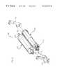
- FIG. 2is an isometric view of the major components of the preferred printer apparatus 10 containing the ribbon tensioning apparatus of the present invention.
- the ribbon 12extends from the ribbon supply reel 22 to the ribbon takeup reel 24 via the path 26 from the first ribbon guide 28 to the second ribbon guide 30 (see FIGS. 1, 6 and 7 ) that passes between the print head 20 and the drive roller 32 at the print point 33 , essentially tangential to the drive roller 32 .
- the print medium 14e.g., a label stock, extends between a print medium guide 35 and the second ribbon guide 30 such that the print medium is sandwiched between the ribbon 12 and the drive roller 32 at the print point 33 .
- a compression member 36e.g., a spring, is elastically coupled to the print head 20 to maintain pressure between the print head 20 and the drive roller 32 as well as pinching the ribbon 12 and the print medium 14 sandwiched between.
- a ribbon supply reel subassembly 37is ,coupled to the ribbon supply reel 22 and torqued in a counter-clockwise direction. Additionally, a ribbon takeup reel subassembly 38 is coupled to the ribbon takeup reel 24 and torqued in a clockwise direction via a common driving means emanating from rotation of a common motor 39 , preferably a stepper motor.
- the common stepper motor 39is preferably coupled to both the drive roller 32 and the ribbon takeup reel subassembly 38 such that a first, e.g., counterclockwise, rotation of the stepper motor 39 causes counter-clockwise rotation of the drive roller 32 which moves the print medium 14 outward in an forward direction, i.e., right to left in FIG. 1 .
- This same rotation of the stepper motor 39is preferably also coupled to increase the clockwise torque of the ribbon takeup reel subassembly 38 .
- Forward movement of the ribbon 12then causes the ribbon supply reel subassembly 37 to be further torqued in a counter-clockwise direction in response to its clockwise rotation as the ribbon 12 is withdrawn.
- the print mediumis a label stock 40 as shown in FIG. 3 .
- adhesive labels 41are detachably mounted on a backing 42 with a short interlabel spacing 43 , relative to the longitudinal size 44 of each label 41 .
- a single label 41 ais printed, it cannot be removed from the backing 42 (as described further below) until the bottom 46 of the current label 41 a is extended well beyond the print point 33 .
- This positioning of the label stock 40results in the print point 33 then being within a next label 41 b , potentially wasting the next label 41 b .
- a controller(not shown), e.g., a microcomputer within the printer 10 , begins each label print operation by first reversing the rotation of the stepper motor 39 and accordingly the drive roller 32 until the beginning 47 of the next label 41 b (now the current label) has been moved back to the print point 33 .
- the reverse rotation of the stepper motor 39is additionally coupled in a counter-clockwise direction to the ribbon takeup reel subassembly 38 through a set of gears (discussed further below) and tends to release torque from the ribbon takeup reel subassembly 38 .
- the torquing mechanism of the ribbon takeup reel subassembly 38is configured to accumulate torque while each label 41 is being printed, i.e., when the ribbon takeup reel 24 is rotated in a clockwise direction as viewed in FIG. 1 .
- the purpose of the ribbon takeup reel subassembly 38is to maintain ribbon tension between the ribbon takeup reel 24 and the print head 20 in the forward direction (right to left in FIG. 1) by providing a clockwise torque.
- the angular rotation of the ribbon takeup reel 24will vary as the diameter of the ribbon takeup reel 24 changes.
- the ribbon tensionneeds to be maintained during the previously described small reverse movement of the label stock 40 . Therefore, embodiments of the present invention preferably include the capabilities to: 1) apply an essentially constant torque to the ribbon takeup reel 24 independent of its rotational speed (since this changes as the ribbon 12 is transferred from the supply to the takeup reel) and 2) accumulate torque to maintain a clockwise torque even during the short reverse label stock movement.
- FIG. 4shows a view of a preferred ribbon takeup reel subassembly 38 , exploded along its rotational axis 48 , which includes these capabilities.
- the ribbon takeup reel subassembly 38is primarily comprised of a takeup hub mating plate 50 , a spring mating hub 52 , a torque spring 54 , a clutch disk 56 , a clutch pad 58 and a clutch hub 60 .
- the takeup hub mating plate 50preferably has an outer toothed surface 62 that is configured to capture reciprocally configured slots 64 (see FIG. 2) in the ribbon takeup reel 24 .
- the ribbon takeup reel 24is tightly held against the outer toothed surface 62 of the takeup hub mating plate 50 as a consequence of a spring loaded hub 66 coupled to the opposing end of the ribbon takeup reel 24 .
- a first shaft 68extends through the centers of the spring mating hub 52 , the torque spring 54 , the clutch disk 56 , the clutch pad 58 and the clutch hub 60 where its outer end is fixedly mated to a centrally located slot 70 in the clutch hub 60 .
- the torque spring 54is coupled at a first end 72 to a first boss 74 on the spring mating hub 52 and at a second end 76 to a second boss 78 on the clutch disk 56 . Consequently, torque can be accumulated in this assembly between the spring mating hub 52 and the clutch disk 56 within the torque spring 54 .
- torqueis stored into this assembly from the stepper motor 39 via a set of gears (described further below) that is coupled to a toothed surface 80 on the spring mating hub 52 .
- a clockwise rotation(as seen looking downward along rotational axis 48 ) imparts a clockwise rotational force to the clutch disk 56 .
- an opposing frictional forceis imparted via the clutch pad 58 to the clutch disk 56 from the clutch hub 60 and this frictional force will cause torque to be accumulated within the torque spring 54 as the clutch disk 56 resists rotation.
- the torquecauses rotation of the clutch hub 60 and consequently the ribbon takeup reel 24 (since the clutch hub 60 is rigidly coupled via the shaft 68 to the takeup hub mating plate 50 ).
- the rotation of the takeup reel 24is limited by the tension on the ribbon 12 which is opposed on the ribbon supply reel 22 by a similar torque storage structure located in the ribbon supply reel subassembly 37 (shown in FIG. 5 ).
- the accumulated energycan be released as frictional energy in the clutch pad 58 as the clutch pad 58 slips against the clutch disk 56 .
- the drive roller 32 and the spring mating hub 52periodically reverse their normal rotations, respectively counter-clockwise and clockwise, to retrieve the label stock after facilitating removal of each printed label by an operator. Consequently, this counter-clockwise rotation of the spring mating hub 52 will also release a portion of the accumulated torque from the torque spring 54 . However, this torque release will also be accompanied by a small reverse movement of the ribbon 12 due to clockwise rotation of the drive roller 32 . Consequently, a small counter-clockwise rotation of the ribbon takeup reel 24 will occur as the ribbon 12 is withdrawn.
- the ribbon supply reel subassembly 37preferably maintains ribbon tension between the ribbon supply reel 22 and the print head 20 during forward movement by providing a torque drag force. Additionally, ribbon tension is preferably maintained during the small reverse movement of the label stock. Therefore, embodiments of the present invention preferably include the capabilities to: 1) apply an essentially constant drag torque to the ribbon supply reel 22 and 2) accumulate torque.
- FIG. 5shows a view of a preferred ribbon supply reel subassembly 37 , exploded along its rotation axis 82 , that includes these capabilities.
- the structure of the ribbon supply subassembly 37mirrors that of the ribbon takeup reel subassembly 38 with two notable exceptions.
- the spring mating hub 84is rotationally fixed and second, the torque spring 85 is formed as a mirror image of the torque spring 54 so that the ribbon supply reel subassembly 37 can accumulate counter-clockwise torque. This torque is released when the ribbon supply reel 22 is permitted to turn in a counter-clockwise direction during the previously described reverse label stock movement.
- the ribbon 12is withdrawn from the ribbon supply reel 22 causing torque to be accumulated in the torque spring 85 and thus presenting an opposing and essentially constant drag force on the ribbon 12 .
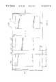
- FIG. 6shows a feed path 86 which is used when the print medium is plain paper.
- Plain paperis freely fed from a rear print medium cavity (not shown) past the print medium guide 35 , a medium width adjustment mechanism 88 , the print point 33 , and then the paper essentially follows path 86 a straight out of the printer 10 .
- the plain papermay follow feed path 86 b which additionally wraps the plain paper around the drive roller 32 and then between the drive roller 32 and a second roller 94 , frictionally driven by the drive roller 32 , before exiting the printer 10 .
- a feed path 90is used. Additionally in the configuration of FIG. 7, a stripper bar 92 is added to the printer 10 . Label stock 40 is freely fed from the rear print medium cavity (not shown) past the print medium guide 35 , the medium width adjustment mechanism 88 , the print point 33 , the stripper bar 92 and then between the drive roller 32 and a stripper roller 94 before exiting the printer 10 along path 90 .
- the stripper roller 94is spring loaded against the drive roller 32 and is permitted to freely rotate in response to rotation of the drive roller 32 .
- the label stock 40moves around the stripper bar 92 before being drawn between the drive roller 32 and the stripper roller 94 . Due to the magnitude of the path change at point 96 , the label 41 a is stripped away from the backing 42 and exits generally along path 98 . The backing 42 , now absent the label 41 a , moves between the drive roller 32 and the stripper roller 94 . After an operator removes the printed and now exposed label 41 a , the printer 10 performs a small reverse movement to realign the next label 41 b to the print point 33 as the next print operation begins.
- Embodiments of the present inventionpreferably include a clam shell structure to ease loading of the ribbon 12 and the print medium 14 .
- the printer 10preferably consists of two main assemblies: 1) a drive subassembly 100 which houses the stepper motor 39 , its internal compound reduction gear, and the drive roller 32 , and 2) a ribbon subassembly 102 which houses the ribbon reels 22 , 24 and the print head 20 .
- the ribbon subassembly 102pivots along axis 104 on the drive subassembly 100 and can be swung away to facilitate threading of the ribbon 12 and the print medium 14 . In its operating position (as shown in FIGS.
- the ribbon subassembly 102is latched to bosses 106 , 108 on the drive subassembly 100 via two latches 110 , 112 , one on each side of the printer 10 .
- a forcee.g., 8 pounds, generated by the compression member 36 on the print head 20 and drive roller 32 is distributed essentially equally between the latches 110 , 112 , e.g., 4 pounds/latch.
- Embodiments of the latching apparatus of the present inventionpreferably cooperatively couple the latches 110 , 112 so that they can be activated by the action of a single lever 113 (as shown in FIG. 2 ).
- a preferred latching apparatusadditionally provides the capability of separating the stripper roller 94 from the drive roller 32 when the latches 110 a , 110 b are unlatched from the bosses 106 , 108 . These capabilities are shown in FIGS. 9 and 10, exploded views of a portion of the latching apparatus 109 .
- the latching apparatus 109is primarily comprised of the two opposing latches 110 , 112 , rigidly coupled to a common shaft 114 which preferably functions as the axle for the stripper roller 94 , a pair of opposing cams 116 , 118 , a drive axle 120 for the drive roller 32 , and the pair of mating latch bosses 106 , 108 , integral to the ribbon subassembly 102 .
- the hooked ends of latches 110 , 112(rotated into positions 110 b , 112 b ) cooperatively engage with latch bosses 106 , 108 as the common shaft 114 is rotated, preferably using the common lever 113 .
- the ribbon subassembly 102is free to rotate into the unlatched position shown in FIG. 8 where loading of the ribbon 12 is facilitated.
- the gap 122also facilitates loading of the label stock 40 which can now be freely fed between the drive roller 32 and the stripper roller 94 .
- FIG. 11schematically shows a preferred gear drive train arrangement used to turn the drive roller 32 and to maintain tension and wind the ribbon 12 .
- idler 124 on the ribbon subassembly 102meshes with a platen gear 126 , integral to the drive axle 120 .
- Rotation of the platen gear 126via the stepper motor 39 and a compound reduction gear 128 , results in rotation of idlers 124 , 130 and thus rotation of the ribbon takeup reel 24 via the spring mating hub 52 .
- the print mediumis supplied from the print medium cavity behind the printer 10 .
- the print mediumis preferably comprised of either a roll of paper or label stock wound around a central hollow core.
- the central hollow coreis mounted around a core axle 134 (shown in FIGS. 12A and 12B, respectively side and top views) having a diameter chosen such that the central hollow core can freely rotate.
- the core axle 134is comprised of first and second essentially rectangular, e.g., oval, ends 136 , 138 and a central support section 140 having an upper concave arc.
- the hollow coreis solely supported by this upper concave arced section 140 of the core axle 134 .
- the first and second ends 136 , 138 of the core axleare non-rotatably inserted into support slots 142 , 144 within a print medium cavity 146 .
- the central hollow coretends to automatically centrally orient itself within the central support section 140 due to its curvature. This structure is of particular use in maintaining alignment of the print medium 14 within the printer 10 .
Landscapes
- Impression-Transfer Materials And Handling Thereof (AREA)
Abstract
Description
Claims (18)
Priority Applications (1)
| Application Number | Priority Date | Filing Date | Title |
|---|---|---|---|
| US09/431,010US6267521B1 (en) | 1995-09-22 | 1999-11-01 | Computer driven printer with a stripper roller and latching assembly |
Applications Claiming Priority (3)
| Application Number | Priority Date | Filing Date | Title |
|---|---|---|---|
| US08/532,083US5820279A (en) | 1995-09-22 | 1995-09-22 | Computer driven printer |
| US09/118,333US6036383A (en) | 1995-09-22 | 1998-07-17 | Computer driven printer |
| US09/431,010US6267521B1 (en) | 1995-09-22 | 1999-11-01 | Computer driven printer with a stripper roller and latching assembly |
Related Parent Applications (1)
| Application Number | Title | Priority Date | Filing Date |
|---|---|---|---|
| US09/118,333DivisionUS6036383A (en) | 1995-09-22 | 1998-07-17 | Computer driven printer |
Publications (1)
| Publication Number | Publication Date |
|---|---|
| US6267521B1true US6267521B1 (en) | 2001-07-31 |
Family
ID=24120316
Family Applications (4)
| Application Number | Title | Priority Date | Filing Date |
|---|---|---|---|
| US08/532,083CeasedUS5820279A (en) | 1995-09-22 | 1995-09-22 | Computer driven printer |
| US09/118,333Expired - LifetimeUS6036383A (en) | 1995-09-22 | 1998-07-17 | Computer driven printer |
| US09/248,606Expired - Fee RelatedUSRE36953E (en) | 1995-09-22 | 1999-02-11 | Computer driven printer |
| US09/431,010Expired - LifetimeUS6267521B1 (en) | 1995-09-22 | 1999-11-01 | Computer driven printer with a stripper roller and latching assembly |
Family Applications Before (3)
| Application Number | Title | Priority Date | Filing Date |
|---|---|---|---|
| US08/532,083CeasedUS5820279A (en) | 1995-09-22 | 1995-09-22 | Computer driven printer |
| US09/118,333Expired - LifetimeUS6036383A (en) | 1995-09-22 | 1998-07-17 | Computer driven printer |
| US09/248,606Expired - Fee RelatedUSRE36953E (en) | 1995-09-22 | 1999-02-11 | Computer driven printer |
Country Status (1)
| Country | Link |
|---|---|
| US (4) | US5820279A (en) |
Cited By (10)
| Publication number | Priority date | Publication date | Assignee | Title |
|---|---|---|---|---|
| US20040178267A1 (en)* | 2003-03-11 | 2004-09-16 | Zebra Technologies Corporation | System and Method for Selective Communication with RFID Transponders |
| US20050045723A1 (en)* | 2003-08-29 | 2005-03-03 | Zih Corp. | Spatially Selective UHF Near Field Microstrip Coupler Device and RFID Systems Using Device |
| US20050274799A1 (en)* | 2004-06-10 | 2005-12-15 | Zih Corp. | Apparatus and method for communicating with an RFID transponder |
| US20060109496A1 (en)* | 2004-11-05 | 2006-05-25 | Zih Corp. | System and method for detecting transponders used with printer media |
| US20070099566A1 (en)* | 2005-10-31 | 2007-05-03 | Zih Corp. | Multi-element RFID coupler |
| US20080298822A1 (en)* | 2007-05-30 | 2008-12-04 | Zih Corp. | System for processing media units and an associated media roll |
| US20090152353A1 (en)* | 2007-12-18 | 2009-06-18 | Zih Corp. | Rfid near-field antenna and associated systems |
| US20090162123A1 (en)* | 2007-12-19 | 2009-06-25 | Zih Corp. | Platen incorporating an rfid coupling device |
| US9061522B2 (en) | 2005-03-16 | 2015-06-23 | Panduit Corp. | Reversible printer assembly |
| US9116641B2 (en) | 2004-11-30 | 2015-08-25 | Panduit Corp. | Market-based labeling system and method |
Families Citing this family (43)
| Publication number | Priority date | Publication date | Assignee | Title |
|---|---|---|---|---|
| JP4080549B2 (en)* | 1997-06-20 | 2008-04-23 | シチズンホールディングス株式会社 | Printer |
| US6130699A (en)* | 1997-07-03 | 2000-10-10 | Datamax Corporation | Thermal ink printer with media supply |
| DE19735182C1 (en)* | 1997-08-14 | 1998-09-24 | Webasto Karosseriesysteme | Tilting support for movable motor vehicle roof |
| US5927875A (en)* | 1997-11-24 | 1999-07-27 | Datamax Corporation | Ribbon tensioning assembly |
| US6478488B1 (en)* | 1999-06-30 | 2002-11-12 | Zih Corp. | Step-stripper roller shaft in an image forming device |
| EP0999067A1 (en)* | 1998-11-03 | 2000-05-10 | Eltron International, Inc. | Ribbon mechanism |
| US7042478B2 (en)* | 1999-03-26 | 2006-05-09 | Datamax Corporation | Modular printer |
| US7699550B2 (en)* | 1999-03-26 | 2010-04-20 | Datamax Corporation | Modular printer |
| US7537404B2 (en)* | 1999-03-26 | 2009-05-26 | Datamax Corporation | Modular printer |
| CA2366533C (en) | 1999-03-26 | 2011-05-31 | Datamax Corporation | Modular printer |
| JP2001158161A (en)* | 1999-12-02 | 2001-06-12 | Fujicopian Co Ltd | Ink ribbon take-up body |
| US6637957B2 (en) | 2000-09-29 | 2003-10-28 | Zih Corp. | Printer with ribbon fold out mechanism and plastic ribbon clutch |
| USD449069S1 (en) | 2001-01-18 | 2001-10-09 | John D. Stouffer | Locking hub |
| USD450758S1 (en) | 2001-01-18 | 2001-11-20 | John D. Stouffer | Locking hub |
| USD457183S1 (en) | 2001-01-18 | 2002-05-14 | John D. Stouffer | Hub |
| US6848845B2 (en)* | 2002-05-08 | 2005-02-01 | Zih Corp. | Thermal ribbon cartridge or roll with slack ribbon retraction |
| USD496684S1 (en) | 2002-06-07 | 2004-09-28 | 3D Systems, Inc. | Feed cartridge for three-dimensional object material |
| JP4216634B2 (en)* | 2003-04-23 | 2009-01-28 | 株式会社日立製作所 | Semiconductor device |
| US20050160935A1 (en)* | 2003-09-18 | 2005-07-28 | William Armstrong | Method for analysis of label positioning and printed image to identify and correct printing anomalies |
| JP2005096161A (en)* | 2003-09-24 | 2005-04-14 | Sanyo Electric Co Ltd | Reel base and recording device using the same |
| US20060062732A1 (en)* | 2004-09-10 | 2006-03-23 | Yasumi Uchida | Medicine for detecting lipid components in vivo and vascular endoscope |
| US20070062636A1 (en)* | 2005-03-01 | 2007-03-22 | Peter Gustafsson | Media gap detection by reflective florescence |
| US7502042B2 (en)* | 2005-05-20 | 2009-03-10 | Datamax Corporation | Laser diode thermal transfer printhead |
| AU2005336512B2 (en)* | 2005-09-12 | 2010-08-26 | Memjet Technology Limited | Feed mechanism for maintaining constant web tension in a wide format printer |
| US20070059082A1 (en)* | 2005-09-12 | 2007-03-15 | Silverbrook Research Pty Ltd | Printhead assembly for a wide format printer |
| US20070059080A1 (en)* | 2005-09-12 | 2007-03-15 | Silverbrook Research Pty Ltd | Take-up spool for a printer |
| US7322761B2 (en)* | 2005-09-12 | 2008-01-29 | Silverbrook Research Pty Ltd | Spool adapted for gripping a roll of print media |
| US20070059079A1 (en)* | 2005-09-12 | 2007-03-15 | Silverbrook Research Pty Ltd | Method of printing with facile removal of print media roll from take-up spool |
| US20070059078A1 (en)* | 2005-09-12 | 2007-03-15 | Silverbrook Research Pty Ltd | Feed mechanism for maintaining constant web tension in a wide format printer |
| US20070059077A1 (en)* | 2005-09-12 | 2007-03-15 | Silverbrook Research Pty Ltd | Wide format printer having a web path adapted for high speed printing |
| US7695204B2 (en)* | 2005-09-12 | 2010-04-13 | Silverbrook Research Pty Ltd | Wide format printer having alternative print zone arrangement |
| JP4760451B2 (en)* | 2006-03-03 | 2011-08-31 | 船井電機株式会社 | Image forming apparatus |
| US20080259111A1 (en)* | 2007-04-20 | 2008-10-23 | Intermec Ip Corp. | Method and apparatus for registering and maintaining registration of a medium in a content applicator |
| CN101544138B (en)* | 2008-03-26 | 2012-05-23 | 山东新北洋信息技术股份有限公司 | Ribbon recovery device for thermal transfer printer |
| US8328442B2 (en)* | 2008-06-13 | 2012-12-11 | Brady Worldwide, Inc. | Printer drive train for providing and maintaining ribbon tension |
| US8882371B2 (en)* | 2010-10-28 | 2014-11-11 | Zih Corp. | Printer with printhead assembly, clutch assembly, and printer ribbon transport assembly |
| US8882374B2 (en) | 2012-05-25 | 2014-11-11 | Datamax—O'Neil Corporation | Printer with print frame interlock and adjustable media support |
| CN103507449B (en)* | 2012-06-29 | 2016-08-03 | 山东新北洋信息技术股份有限公司 | Carbon ribbon recovering mechanism and use the thermal transfer printer of this mechanism |
| TWI600553B (en) | 2015-08-19 | 2017-10-01 | 立象科技股份有限公司 | Torque limiter |
| JP7043286B2 (en)* | 2017-09-27 | 2022-03-29 | シチズン時計株式会社 | Ink ribbon feed mechanism and printer |
| CN109263312B (en)* | 2018-11-30 | 2023-09-01 | 硕方科技(北京)有限公司 | Printer medium transmission clutch brake assembly and printer |
| CN110202959A (en)* | 2019-04-26 | 2019-09-06 | 深圳市普实科技有限公司 | A kind of portable printer |
| CN118418585A (en)* | 2023-02-02 | 2024-08-02 | 手持产品公司 | Printer driving mechanism |
Citations (11)
| Publication number | Priority date | Publication date | Assignee | Title |
|---|---|---|---|---|
| US4262591A (en)* | 1978-12-18 | 1981-04-21 | Robert C. Cook | Office label printer and dispenser |
| US4712114A (en)* | 1985-09-28 | 1987-12-08 | Kabushiki Kaisha Sato | Label feeding apparatus for a thermal label printer |
| US4754290A (en)* | 1986-04-11 | 1988-06-28 | Mitsubishi Denki Kabushiki Kaisha | Printing apparatus equipped with a loading mechanism for an inksheet cassette |
| US4910602A (en)* | 1984-06-12 | 1990-03-20 | Canon Kabushiki Kaisha | Thermal recorder with ink sheet cassette removably mounted in openable housing |
| US5174669A (en)* | 1989-09-04 | 1992-12-29 | Tokyo Electric Co., Ltd. | Label separating device in label printer |
| US5336003A (en)* | 1992-02-20 | 1994-08-09 | Tokyo Electric Co., Ltd. | Label printer |
| US5480244A (en)* | 1993-04-30 | 1996-01-02 | Kabushiki Kaisha Tec | Article information printer having means to measure print media size |
| US5570121A (en)* | 1993-12-20 | 1996-10-29 | Monarch Marking Systems, Inc. | Printer |
| US5785442A (en)* | 1993-10-15 | 1998-07-28 | Monarch Marking Systems, Inc. | Printer housing structure |
| US6010257A (en)* | 1997-03-18 | 2000-01-04 | Comtec Information Systems Inc. | Miniature portable interactive printer |
| US6068419A (en)* | 1995-04-27 | 2000-05-30 | Toshiba Tec Kabushiki Kaisha (Toshiba Tec Corporation) | Label printer |
Family Cites Families (13)
| Publication number | Priority date | Publication date | Assignee | Title |
|---|---|---|---|---|
| JPS5316886A (en)* | 1976-07-29 | 1978-02-16 | Tatsuta Densen Kk | Method of manufacturing flexible cable by nonncage type winding and twisting process |
| JPS6241070A (en)* | 1985-08-20 | 1987-02-23 | Sanyo Electric Co Ltd | Thermal transfer recorder |
| US5032032A (en)* | 1986-06-04 | 1991-07-16 | Primages, Inc. | Ribbon cassette responsive to ribbon breakage |
| JPS6484961A (en)* | 1987-09-25 | 1989-03-30 | Nec Corp | System for processing receiving subaddress |
| JP2511304Y2 (en)* | 1988-12-19 | 1996-09-25 | ミノルタ株式会社 | Thermal transfer printer |
| JP2544485B2 (en)* | 1989-07-14 | 1996-10-16 | 株式会社テック | Printer |
| JP3050622B2 (en)* | 1991-03-27 | 2000-06-12 | シャープ株式会社 | Printing device |
| JP2783055B2 (en)* | 1992-04-20 | 1998-08-06 | 松下電器産業株式会社 | Terminal equipment |
| JP3047202B2 (en)* | 1992-04-27 | 2000-05-29 | 株式会社サトー | Prevention mechanism of carbon ribbon slack of printing device |
| JP2690659B2 (en)* | 1992-05-25 | 1997-12-10 | 株式会社テック | Label printer |
| JP3694331B2 (en)* | 1994-03-25 | 2005-09-14 | 株式会社サトー | Ink ribbon cassette device in thermal transfer printer |
| US5529410A (en)* | 1994-10-28 | 1996-06-25 | Pitney Bowes Inc. | Method and apparatus for controlling tension on a sheet material in a reel-to-reel transport system |
| US5775632A (en)* | 1996-06-03 | 1998-07-07 | Huerta; Joe A. | Mandrel for use with an apparatus for dispensing material from a roll |
- 1995
- 1995-09-22USUS08/532,083patent/US5820279A/ennot_activeCeased
- 1998
- 1998-07-17USUS09/118,333patent/US6036383A/ennot_activeExpired - Lifetime
- 1999
- 1999-02-11USUS09/248,606patent/USRE36953E/ennot_activeExpired - Fee Related
- 1999-11-01USUS09/431,010patent/US6267521B1/ennot_activeExpired - Lifetime
Patent Citations (11)
| Publication number | Priority date | Publication date | Assignee | Title |
|---|---|---|---|---|
| US4262591A (en)* | 1978-12-18 | 1981-04-21 | Robert C. Cook | Office label printer and dispenser |
| US4910602A (en)* | 1984-06-12 | 1990-03-20 | Canon Kabushiki Kaisha | Thermal recorder with ink sheet cassette removably mounted in openable housing |
| US4712114A (en)* | 1985-09-28 | 1987-12-08 | Kabushiki Kaisha Sato | Label feeding apparatus for a thermal label printer |
| US4754290A (en)* | 1986-04-11 | 1988-06-28 | Mitsubishi Denki Kabushiki Kaisha | Printing apparatus equipped with a loading mechanism for an inksheet cassette |
| US5174669A (en)* | 1989-09-04 | 1992-12-29 | Tokyo Electric Co., Ltd. | Label separating device in label printer |
| US5336003A (en)* | 1992-02-20 | 1994-08-09 | Tokyo Electric Co., Ltd. | Label printer |
| US5480244A (en)* | 1993-04-30 | 1996-01-02 | Kabushiki Kaisha Tec | Article information printer having means to measure print media size |
| US5785442A (en)* | 1993-10-15 | 1998-07-28 | Monarch Marking Systems, Inc. | Printer housing structure |
| US5570121A (en)* | 1993-12-20 | 1996-10-29 | Monarch Marking Systems, Inc. | Printer |
| US6068419A (en)* | 1995-04-27 | 2000-05-30 | Toshiba Tec Kabushiki Kaisha (Toshiba Tec Corporation) | Label printer |
| US6010257A (en)* | 1997-03-18 | 2000-01-04 | Comtec Information Systems Inc. | Miniature portable interactive printer |
Cited By (31)
| Publication number | Priority date | Publication date | Assignee | Title |
|---|---|---|---|---|
| US20050092838A1 (en)* | 2003-03-11 | 2005-05-05 | Zih Corp., A Delaware Corporation With Its Princip | System and Method for Selective Communication with RFID Transponders |
| US6848616B2 (en) | 2003-03-11 | 2005-02-01 | Zih Corp., A Delaware Corporation With Its Principal Office In Hamilton, Bermuda | System and method for selective communication with RFID transponders |
| US20040178267A1 (en)* | 2003-03-11 | 2004-09-16 | Zebra Technologies Corporation | System and Method for Selective Communication with RFID Transponders |
| US7650114B2 (en) | 2003-08-29 | 2010-01-19 | Zih Corp. | Spatially selective UHF near field microstrip coupler device and RFID systems using device |
| US8351959B2 (en) | 2003-08-29 | 2013-01-08 | Zih Corp. | Spatially selective UHF near field microstrip coupler device and RFID systems using device |
| US20050045723A1 (en)* | 2003-08-29 | 2005-03-03 | Zih Corp. | Spatially Selective UHF Near Field Microstrip Coupler Device and RFID Systems Using Device |
| US8160493B2 (en) | 2003-08-29 | 2012-04-17 | Zih Corp. | Spatially selective UHF near field microstrip coupler device and RFID systems using device |
| US7398054B2 (en) | 2003-08-29 | 2008-07-08 | Zih Corp. | Spatially selective UHF near field microstrip coupler device and RFID systems using device |
| US9852318B2 (en) | 2003-08-29 | 2017-12-26 | Zih Corp. | Spatially selective UHF near field microstrip coupler device and RFID systems using device |
| US20090008448A1 (en)* | 2003-08-29 | 2009-01-08 | Zih Corp. | Spatially selective uhf near field microstrip coupler device and rfid systems using device |
| US8544740B2 (en) | 2004-06-10 | 2013-10-01 | Zih Corp. | Apparatus and method for communicating with an RFID transponder |
| US8596532B2 (en) | 2004-06-10 | 2013-12-03 | Zih Corp. | Apparatus and method for communicating with an RFID transponder |
| US20050274799A1 (en)* | 2004-06-10 | 2005-12-15 | Zih Corp. | Apparatus and method for communicating with an RFID transponder |
| US9613242B2 (en) | 2004-06-10 | 2017-04-04 | Zih Corp. | Apparatus and method for communicating with an RFID transponder |
| US7489243B2 (en) | 2004-11-05 | 2009-02-10 | Zih Corp. | System and method for detecting transponders used with printer media |
| US20070176781A1 (en)* | 2004-11-05 | 2007-08-02 | Zih Corp. | System and method for detecting transponders used with printer media |
| US7190270B2 (en) | 2004-11-05 | 2007-03-13 | Zih Corp. | System and method for detecting transponders used with printer media |
| US20060109496A1 (en)* | 2004-11-05 | 2006-05-25 | Zih Corp. | System and method for detecting transponders used with printer media |
| US9116641B2 (en) | 2004-11-30 | 2015-08-25 | Panduit Corp. | Market-based labeling system and method |
| US9061522B2 (en) | 2005-03-16 | 2015-06-23 | Panduit Corp. | Reversible printer assembly |
| US20070099566A1 (en)* | 2005-10-31 | 2007-05-03 | Zih Corp. | Multi-element RFID coupler |
| US8306474B2 (en)* | 2005-10-31 | 2012-11-06 | Zih Corp. | Multi-element RFID coupler |
| US20120108170A1 (en)* | 2005-10-31 | 2012-05-03 | Zih Corp. | Multi-element rfid coupler |
| US8078103B2 (en)* | 2005-10-31 | 2011-12-13 | Zih Corp. | Multi-element RFID coupler |
| US9391675B2 (en) | 2005-10-31 | 2016-07-12 | Zih Corp. | Multi-element RFID coupler |
| US9524460B2 (en) | 2007-05-30 | 2016-12-20 | Zih Corp. | System for processing media units and an associated media roll |
| US20080298822A1 (en)* | 2007-05-30 | 2008-12-04 | Zih Corp. | System for processing media units and an associated media roll |
| US9108434B2 (en) | 2007-12-18 | 2015-08-18 | Zih Corp. | RFID near-field antenna and associated systems |
| US20090152353A1 (en)* | 2007-12-18 | 2009-06-18 | Zih Corp. | Rfid near-field antenna and associated systems |
| US20090162123A1 (en)* | 2007-12-19 | 2009-06-25 | Zih Corp. | Platen incorporating an rfid coupling device |
| US9415611B2 (en) | 2007-12-19 | 2016-08-16 | Zih Corp. | Platen incorporating an RFID coupling device |
Also Published As
| Publication number | Publication date |
|---|---|
| US6036383A (en) | 2000-03-14 |
| US5820279A (en) | 1998-10-13 |
| USRE36953E (en) | 2000-11-14 |
Similar Documents
| Publication | Publication Date | Title |
|---|---|---|
| US6267521B1 (en) | Computer driven printer with a stripper roller and latching assembly | |
| US4944619A (en) | Construction for mounting an ink ribbon cassette in a heat transferable line printer | |
| US5295753A (en) | Label tape printing system using thermal head and transfer ink ribbon | |
| US4468139A (en) | Printing apparatus with a thermal print head including ribbon cartridge | |
| EP0156610B1 (en) | Ink-transfer thermal printer | |
| EP0200938B1 (en) | Transfer medium feed mechanism for printers | |
| KR940010996B1 (en) | Thermal printer | |
| EP0422649B1 (en) | Thermal printer | |
| JPH05301405A (en) | Mechanism for preventing carbon ribbon from relaxing in printing apparatus | |
| US5143461A (en) | Printer | |
| US4611937A (en) | Ribbon feed mechanism for a printer | |
| US6313861B2 (en) | Thermal transfer printer with print film saving system and print media tensioning system | |
| JPS61195881A (en) | Thermal transfer type printer | |
| US4755833A (en) | Thermal transfer printer | |
| KR20050006166A (en) | Thermal ribbon cartridge or roll with slack ribbon retraction | |
| EP0301076B1 (en) | Card ejecting apparatus | |
| JP3038128B2 (en) | Ink ribbon winding device | |
| JP3153675B2 (en) | Thermal transfer recording device | |
| JP2502150Y2 (en) | Cassette type label printer | |
| JP5599578B2 (en) | Thermal printer | |
| JP3325761B2 (en) | Ribbon cassette | |
| JP3041142B2 (en) | Printer device | |
| JPH029985Y2 (en) | ||
| JP3121725B2 (en) | Thermal transfer printer | |
| JPS63149172A (en) | Thermal printer |
Legal Events
| Date | Code | Title | Description |
|---|---|---|---|
| AS | Assignment | Owner name:ZIH CORP., DELAWARE Free format text:ASSIGNMENT OF ASSIGNORS INTEREST;ASSIGNOR:ELTRON INTERNATIONAL, INC.;REEL/FRAME:011369/0594 Effective date:20001113 | |
| STCF | Information on status: patent grant | Free format text:PATENTED CASE | |
| AS | Assignment | Owner name:ZIH CORP., BERMUDA Free format text:RECORDATION OF ASSIGNEE'S PRINCIPAL PLACE OF BUSIN;ASSIGNOR:ZIH CORP.;REEL/FRAME:014154/0051 Effective date:20031104 | |
| FEPP | Fee payment procedure | Free format text:PAYOR NUMBER ASSIGNED (ORIGINAL EVENT CODE: ASPN); ENTITY STATUS OF PATENT OWNER: LARGE ENTITY | |
| FPAY | Fee payment | Year of fee payment:4 | |
| FPAY | Fee payment | Year of fee payment:8 | |
| FPAY | Fee payment | Year of fee payment:12 | |
| AS | Assignment | Owner name:MORGAN STANLEY SENIOR FUNDING, INC. AS THE COLLATERAL AGENT, MARYLAND Free format text:SECURITY AGREEMENT;ASSIGNORS:ZIH CORP.;LASER BAND, LLC;ZEBRA ENTERPRISE SOLUTIONS CORP.;AND OTHERS;REEL/FRAME:034114/0270 Effective date:20141027 Owner name:MORGAN STANLEY SENIOR FUNDING, INC. AS THE COLLATE Free format text:SECURITY AGREEMENT;ASSIGNORS:ZIH CORP.;LASER BAND, LLC;ZEBRA ENTERPRISE SOLUTIONS CORP.;AND OTHERS;REEL/FRAME:034114/0270 Effective date:20141027 | |
| AS | Assignment | Owner name:JPMORGAN CHASE BANK, N.A., AS THE SUCCESSOR AGENT, NEW YORK Free format text:PATENT SECURITY INTEREST ASSIGNMENT AGREEMENT;ASSIGNOR:MORGAN STANLEY SENIOR FUNDING, INC., AS THE EXISTING AGENT;REEL/FRAME:044791/0842 Effective date:20170907 Owner name:JPMORGAN CHASE BANK, N.A., AS THE SUCCESSOR AGENT, Free format text:PATENT SECURITY INTEREST ASSIGNMENT AGREEMENT;ASSIGNOR:MORGAN STANLEY SENIOR FUNDING, INC., AS THE EXISTING AGENT;REEL/FRAME:044791/0842 Effective date:20170907 | |
| AS | Assignment | Owner name:ZEBRA TECHNOLOGIES CORPORATION, ILLINOIS Free format text:MERGER;ASSIGNOR:ZIH CORP.;REEL/FRAME:048884/0618 Effective date:20181220 |