US6267502B1 - Alignment verification device and method of using the same with a visual light beam and an x-ray - Google Patents
Alignment verification device and method of using the same with a visual light beam and an x-rayDownload PDFInfo
- Publication number
- US6267502B1 US6267502B1US09/087,365US8736598AUS6267502B1US 6267502 B1US6267502 B1US 6267502B1US 8736598 AUS8736598 AUS 8736598AUS 6267502 B1US6267502 B1US 6267502B1
- Authority
- US
- United States
- Prior art keywords
- ray
- light beam
- radio
- visible light
- opaque
- Prior art date
- Legal status (The legal status is an assumption and is not a legal conclusion. Google has not performed a legal analysis and makes no representation as to the accuracy of the status listed.)
- Expired - Fee Related
Links
- 238000000034methodMethods0.000titleclaimsabstractdescription44
- 230000000007visual effectEffects0.000titleclaims5
- 238000012795verificationMethods0.000titledescription13
- 239000000463materialSubstances0.000claimsdescription9
- 230000003287optical effectEffects0.000claims2
- 210000004209hairAnatomy0.000claims1
- 238000003384imaging methodMethods0.000abstractdescription4
- 239000000853adhesiveSubstances0.000description4
- 230000001070adhesive effectEffects0.000description4
- 238000007920subcutaneous administrationMethods0.000description4
- 239000003550markerSubstances0.000description3
- 230000008685targetingEffects0.000description2
- 238000001574biopsyMethods0.000description1
- 238000002316cosmetic surgeryMethods0.000description1
- 230000009977dual effectEffects0.000description1
- 239000007943implantSubstances0.000description1
- 238000012986modificationMethods0.000description1
- 230000004048modificationEffects0.000description1
- 229920003023plasticPolymers0.000description1
- 230000005855radiationEffects0.000description1
Images


Classifications
- A—HUMAN NECESSITIES
- A61—MEDICAL OR VETERINARY SCIENCE; HYGIENE
- A61B—DIAGNOSIS; SURGERY; IDENTIFICATION
- A61B6/00—Apparatus or devices for radiation diagnosis; Apparatus or devices for radiation diagnosis combined with radiation therapy equipment
- A61B6/08—Auxiliary means for directing the radiation beam to a particular spot, e.g. using light beams
- A—HUMAN NECESSITIES
- A61—MEDICAL OR VETERINARY SCIENCE; HYGIENE
- A61N—ELECTROTHERAPY; MAGNETOTHERAPY; RADIATION THERAPY; ULTRASOUND THERAPY
- A61N5/00—Radiation therapy
- A61N5/10—X-ray therapy; Gamma-ray therapy; Particle-irradiation therapy
- A61N5/1048—Monitoring, verifying, controlling systems and methods
- A61N5/1049—Monitoring, verifying, controlling systems and methods for verifying the position of the patient with respect to the radiation beam
- A61N2005/1056—Monitoring, verifying, controlling systems and methods for verifying the position of the patient with respect to the radiation beam by projecting a visible image of the treatment field
Definitions
- the inventionrelates generally to the field of aligning an x-ray and a visible light beam in a fluoroscope. More particularly, the invention relates to a device containing a radio-opaque material that provides a means to check for precise physical alignment between an x-ray in a fluoroscope and a laser beam in a laser targeting system attached to the fluoroscope.
- Producing and positioning a laser beam that indicates the exact surface point of entry and the precise angle of approach to a subcutaneous structurecan be used in many fluoroscopically guided procedures, such as biopsies of deep tissue anatomy, screw, wire and implant placement, vertebroplasty, spinal procedures, arthrograms, selected interventional cardiology, and craniofacial and plastic surgery procedures.
- the laser or other visible light beamusually serves as an accurate visible guide for accessing a subcutaneous structure.
- U.S. Pat. Nos. 5,212,720 and 5,644,616 to Landi et al.disclose a technique that uses a calibration device with a marking made of radio-opaque material for coaxially and coincidentally aligning a laser beam with the central ray from an x-ray source.
- U.S. Pat. No. 5,193,106 to DeSenadiscloses a device for providing percutaneous-based markings in association with x-ray examination procedures.
- the DeSena patentshows a tape having adhesive backing with a radio-opaque marker made of radio-opaque material affixed to the tape.
- the radio-opaque markerencloses an area of interest and serves to focus the attention of a podiatrist reviewing an x-ray photograph of the area of interest.
- U.S. Pat. No. 4,698,836 to Minasiandiscloses a radio-opaque movable ball disposed within a dish shaped opening. The ball is used to record position information on a patient's x-ray film. None of these patents uses a radio-opaque member to verify alignment between an x-ray and a visible light beam in a fluoroscope or any other kind of x-ray equipment. Moreover, none of these patents discloses a method and device for verifying alignment of the visible light beam in the light beam source itself.
- the system of aligning an x-ray beam with a visible light beamcomprises a visible light source with a colinearizer that are attached to an x-ray machine such as a fluoroscope.
- the colinearizerincludes a pair of reticles mounted at each end of the colinearizer.
- Each reticlehas radio-opaque cross-hairs that produce an image of the reticles on a x-ray image.
- Such system and methoddo not take into account the fact that the visible light beam may deflect from its intended direction inside the colinearizer when, for example, the fluoroscope is moved or when the visible light source is somehow disturbed.
- the alignment of the two reticles in the colinearizer with respect to the x-raydoes not solve the problem of verifying the alignment of the visible light beam inside the visible light beam source itself.
- the Landi et al. systems and methodspresume that if the colinearizer is aligned with the x-ray beam, the visible light beam will necessarily always be properly aligned with the x-ray.
- a doctorcould verify the alignment between the visible light beam and the x-ray as well as between the visible light beam and the source of the visible light beam itself and then print out an image corresponding to the correctly aligned equipment, the doctor would have proof of the fact that he or she operated properly functioning, precisely aligned equipment. Therefore, it would be desirable to have a device and method for verifying alignment of the direction of the visible light beam with respect to the colinearizer in addition to the alignment with respect to the direction of the central ray of the x-ray beam.
- a body of radio-opaque materialis incorporated into a supporting member coated or covered with an adhesive.
- the devicecan be removably attached to an image intensifier of an x-ray machine which both the x-rays and the visible light beam impinge upon.
- the two reticle imageswill form a single superimposed reticle image on a monitor.
- the alignment verification deviceis placed on the image intensifier so that the visible light beam and the radio-opaque body are in direct alignment. In such an arrangement the position of the radio-opaque material indicates the place where the visible light beam hits the image intensifier.
- the position of the image of the radio-opaque body in an x-ray image relative to the center of the reticle imagewill indicate the position of the visible light beam relative to the colinearizer, and therefore, to the x-rays.
- the visible light beamis realigned with the colinearizer and the alignment verification procedure is repeated.
- FIG. 1is a schematic representation of non-aligned visible light beam and x-rays in an x-ray machine.
- FIG. 2is a schematic representation of aligned visible light beam and x-rays in an x-ray machine.
- FIG. 3Ais a schematic representation of non-aligned colinearizer and x-rays.
- FIG. 3Bis an image formed by cross-hairs of two reticles when the colinearizer is not aligned with the x-rays.
- FIG. 3Cis a schematic representation of aligned colinearizer and x-rays.
- FIG. 3Dis a superimposed image formed by cross-hairs of two reticles when the colinearizer is aligned with the x-rays.
- FIG. 4is a schematic representation of misalignment between a visible light beam and a colinearizer.
- FIG. 5Ais a top view of an alignment verification device of the present invention.
- FIG. 5Bis a side view of the alignment verification device of the present invention.
- FIG. 5Cis a perspective view of the alignment verification device with a peel-off covering.
- FIG. 6is a schematic representation of an x-ray machine as used with the alignment verification device.
- FIG. 7Ais a representation of an image corresponding to precise alignment between a visible light beam and x-rays.
- FIG. 7Bis a representation of an image corresponding to misalignment between the visible light beam and the x-rays.
- the device and method of the present inventionare used with C-Arm fluoroscope machines, such as the ones manufactured by OEC, Siemens, General Electric, Phillips, Toshiba and others.
- a system comprising a visible light sourceattaches to the fluoroscope.
- An example of a system with a visible light source suitable for use with a C-Arm fluoroscopeis the Dual Radiation Targeting System (DRTSTM) platform described in U.S. Pat. Nos. 5,212,720 and 5,644,616 to Landi et al., which patents are incorporated herein by reference.
- DRTSTMDual Radiation Targeting System
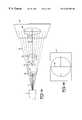
- x-rays 10exit an x-ray source 12 of a fluoroscope in a conical array. As the x-rays pass through a target 14 , they form an image 16 of target 14 on a monitor 18 .
- a visible light source 20 that is attached to the fluoroscopegenerates a visible light beam 22 .
- visible light beam 22 and a central x-ray 24are coaxially and coincidentally unaligned. Because beam 22 and central x-ray 24 are unaligned, point A 1 of image 16 on monitor 18 appears to be the point of entry at which beam 22 impinges upon image 16 .
- point A of target 14 that corresponds to point A 1 of image 16is not the point of entry of beam 22 , as illustrated in FIG. 1 . Therefore, when beam 22 and central x-ray 24 are unaligned, the information of the relative positions of target 14 and beam 22 provided by image 16 is incorrect. If beam 22 and central x-ray 24 are coaxially and coincidentally aligned, as illustrated in FIG. 2, then the point of entry B on target 14 correctly corresponds to the point of entry B 1 on image 16 formed on monitor 18 .
- the DRTSTM platformutilizes a visible light source 20 that generates visible light beam 22 along a central axis Z of a colinearizer 26 , as shown in FIG. 3A.
- a pair of reticles 28 and 30are inserted at each end of colinearizer 26 .
- Each reticlehas radio-opaque cross-hairs 32 and 34 marked on the reticles.
- radio-opaque cross-hairs 32 and 34will produce two separate unaligned reticle images 36 and 38 on monitor 18 , as illustrated in FIG.
- the above-described alignment mechanismprovides correct alignment only when the direction of visible light beam 22 coincides with the direction of axis Z of colinearizer 26 . If for any reason the direction of visible light beam 22 is not coaxial with axis Z of colinearizer 26 , then a single reticle image 40 of superimposed radio-opaque cross-hairs will not be indicative of visible light beam 22 being coaxially aligned with central x-ray 24 , as shown in FIG. 4 . Indeed, as illustrated in FIG.
- axis Z of colinearizer 26 and central x-ray 24are coaxial, but visible light beam 22 is not coaxial with central x-ray 24 even thought a single superimposed image 40 of two reticles will indicate, falsely in this case, proper alignment between visible light beam 22 and central x-ray 24 .
- the alignment verification device of the present inventionis used to check the accuracy of the actual alignment between visible light beam 22 and central x-ray 24 .
- FIG. 5 AThe embodiment shows a device 50 comprising a supporting member 52 capable of attaching device 50 to a surface that is impinged upon by visible light beam 22 (not shown).
- supporting member 52is in the form of a strip, a part 54 of which is covered by an adhesive for attaching member 52 to an x-ray machine.
- strip 52can be made of a transparent plastic material.
- the preferred embodimentcontemplates that part 54 which is covered or coated with the adhesive is also covered by a removable peel-off covering 58 , as illustrated in FIG. 5 C.
- Supporting member 52incorporates into it a three-dimensional radio-opaque body 56 which is permanently attached to supporting member 52 .
- three-dimensional radio-opaque body 56is a spherically shaped member made of lead located in the center of a strip-like supporting member 52 , as illustrated in FIGS. 5A, 5 B and 5 C. It is contemplated by the present invention that three-dimensional radio-opaque body 56 can be made of any radio-opaque material.
- the diameter of the spherically shaped memberpreferably is within the range of 0.5 mm to 2 mm.
- Strip-like supporting member 52is preferably from 2 cm to 20 cm long and from 0.5 cm to 5 cm wide.
- part 54comprises a plurality of circles ( 51 and 53 in FIG. 5A) that help a person to align visible light beam 22 and radio-opaque body 56 .
- the preferred embodiment of the present inventioncalls for the diameter of the spherically shaped member to be comparable to the cross-section of visible light beam 22 to facilitate a person aligning light beam 22 with body 56 .
- Alignment verification device 50 of the present inventioncalls for the following procedure of achieving verification of alignment of visible light beam 22 from visible light beam source 20 and central x-ray 24 , as shown in FIG. 6 .
- conical array of x-ray 10turned on in an x-ray machine 60
- visible light beam 22is aligned with central x-ray 24 by aligning colinearizer 26 and central x-ray 24 using reticles 28 and 30 to obtain a single superimposed reticle image like image 40 , as described above in connection with FIGS. 3C and 3D.
- colinearizer 26 and central x-ray 24are in alignment, x-ray 10 is turned off and visible light beam 22 is turned on.
- alignment verification device 50 of the present inventionis attached to image intensifier 62 of x-ray machine 60 so that three-dimensional radio-opaque member 56 is in direct alignment with visible light beam 22 , as illustrated in FIG. 6 .
- a userWith x-ray 10 turned on again and visible light beam 22 off, a user then observes a position of an image 70 of three-dimensional radio-opaque member 56 in an x-ray image on monitor 18 relative to the center of aligned superimposed reticles 40 , as illustrated in FIGS. 7A and 7B. If image 70 coincides with the intersection of radio-opaque cross-hairs of aligned superimposed reticles 40 on monitor 18 , as shown in FIG. 7A, it means that visible light beam 22 and central x-ray 24 are indeed in alignment. If, on the other hand, image 70 does not fall in the intersection of aligned superimposed reticles 40 , as illustrated in FIG.
- the visible light beam described abovecan be any collimated visible light beam, in the preferred embodiment of the present invention the visible light beam is a laser beam.
Landscapes
- Health & Medical Sciences (AREA)
- Life Sciences & Earth Sciences (AREA)
- Medical Informatics (AREA)
- Engineering & Computer Science (AREA)
- Radiology & Medical Imaging (AREA)
- Biomedical Technology (AREA)
- Biophysics (AREA)
- Nuclear Medicine, Radiotherapy & Molecular Imaging (AREA)
- Optics & Photonics (AREA)
- Pathology (AREA)
- Physics & Mathematics (AREA)
- High Energy & Nuclear Physics (AREA)
- Heart & Thoracic Surgery (AREA)
- Molecular Biology (AREA)
- Surgery (AREA)
- Animal Behavior & Ethology (AREA)
- General Health & Medical Sciences (AREA)
- Public Health (AREA)
- Veterinary Medicine (AREA)
- Apparatus For Radiation Diagnosis (AREA)
Abstract
Description
Claims (20)
Priority Applications (1)
| Application Number | Priority Date | Filing Date | Title |
|---|---|---|---|
| US09/087,365US6267502B1 (en) | 1998-04-10 | 1998-05-29 | Alignment verification device and method of using the same with a visual light beam and an x-ray |
Applications Claiming Priority (2)
| Application Number | Priority Date | Filing Date | Title |
|---|---|---|---|
| US8139698P | 1998-04-10 | 1998-04-10 | |
| US09/087,365US6267502B1 (en) | 1998-04-10 | 1998-05-29 | Alignment verification device and method of using the same with a visual light beam and an x-ray |
Publications (1)
| Publication Number | Publication Date |
|---|---|
| US6267502B1true US6267502B1 (en) | 2001-07-31 |
Family
ID=26765544
Family Applications (1)
| Application Number | Title | Priority Date | Filing Date |
|---|---|---|---|
| US09/087,365Expired - Fee RelatedUS6267502B1 (en) | 1998-04-10 | 1998-05-29 | Alignment verification device and method of using the same with a visual light beam and an x-ray |
Country Status (1)
| Country | Link |
|---|---|
| US (1) | US6267502B1 (en) |
Cited By (29)
| Publication number | Priority date | Publication date | Assignee | Title |
|---|---|---|---|---|
| WO2004034909A1 (en)* | 2002-10-16 | 2004-04-29 | H:S Bispebjerg Hospital | Pointer for a radiographic device |
| US20040188645A1 (en)* | 2003-03-25 | 2004-09-30 | Fuji Photo Film Co., Ltd. | Quality control system for irradiation apparatus |
| US20040247076A1 (en)* | 2003-04-03 | 2004-12-09 | Nassir Navab | Real-time acquisition of co-registered X-ray and optical images |
| US20050232398A1 (en)* | 2004-03-01 | 2005-10-20 | Heiko Kopping | Device fittable to the therapy head of an x-ray guided lithotripsy system to allow adjustment of the focus thereof |
| US20060018438A1 (en)* | 2004-07-21 | 2006-01-26 | Sohal Ratanjit S | System and method for alignment of an object in a medical imaging device |
| US20060126796A1 (en)* | 2004-12-10 | 2006-06-15 | Joseph Hecker | Laser guides for X-ray device |
| US20060155296A1 (en)* | 2005-01-07 | 2006-07-13 | Celonova Biosciences, Inc. | Three-dimensional implantable bone support |
| US20070071176A1 (en)* | 2005-09-23 | 2007-03-29 | William Main | Integrated quality assurance for an image guided radiation treatment delivery system |
| US20080240364A1 (en)* | 2007-03-29 | 2008-10-02 | Main William T | Phantom insert for quality assurance |
| US20090190722A1 (en)* | 2008-01-28 | 2009-07-30 | Reflective X-Ray Optics Llc | Optical alignment system and alignment method for radiographic x-ray imaging |
| EP1682003A4 (en)* | 2003-10-31 | 2010-03-17 | Minrad Inc | Targeting system and method of targeting |
| US20100191371A1 (en)* | 2009-01-28 | 2010-07-29 | Oliver Hornung | Monitoring of a medical device |
| US20100246777A1 (en)* | 2009-03-26 | 2010-09-30 | Thompson Gerald D | Laser targeting companion system used with medical imaging devices |
| US20110190776A1 (en)* | 2009-12-18 | 2011-08-04 | Palmaz Scientific, Inc. | Interosteal and intramedullary implants and method of implanting same |
| FR2956979A1 (en)* | 2010-03-05 | 2011-09-09 | Qualiformed Sarl | OBJECT-TEST AND METHOD USING THE TEST-OBJECT FOR CONTROLLING THE COINCIDENCE OF LUMINOUS FIELDS AND IRRADIATED FIELDS ON A RADIOTHERAPY TREATMENT APPARATUS |
| WO2012009560A3 (en)* | 2010-07-16 | 2012-04-05 | University Of Florida Research Foundation, Inc. | Digital x-ray field and light field alignment |
| US20120163539A1 (en)* | 2010-12-22 | 2012-06-28 | Van Der Veen Johannes Simon | Mobile x-ray unit |
| US20120163551A1 (en)* | 2010-12-22 | 2012-06-28 | Jager Wim De | Mobile x-ray unit |
| US9439619B1 (en) | 2015-04-16 | 2016-09-13 | Kirby Nance | Targeting system for use with x-ray machines |
| US9510771B1 (en) | 2011-10-28 | 2016-12-06 | Nuvasive, Inc. | Systems and methods for performing spine surgery |
| US20170065246A1 (en)* | 2015-09-08 | 2017-03-09 | Samsung Electronics Co., Ltd | X-ray imaging apparatus and control method for the same |
| US9592109B2 (en) | 2013-03-12 | 2017-03-14 | Covidien Lp | Hernia mesh placement system and method for in-situ surgical applications |
| US9848922B2 (en) | 2013-10-09 | 2017-12-26 | Nuvasive, Inc. | Systems and methods for performing spine surgery |
| WO2019079543A1 (en)* | 2017-10-20 | 2019-04-25 | Trinity Orthopedics, Llc | Imager-based positioning and guidance system and methods of use |
| CN110559076A (en)* | 2019-10-18 | 2019-12-13 | 庄源东 | intraoperative ray perspective combined visible light image fusion system |
| US11282202B2 (en)* | 2019-03-08 | 2022-03-22 | William E. Butler | Temporal calibration of an angiographic imaging system |
| WO2023055870A1 (en)* | 2021-09-29 | 2023-04-06 | University Of Kentucky Research Foundation | Quality assurance system and method |
| WO2025110085A1 (en)* | 2023-11-20 | 2025-05-30 | 株式会社島津製作所 | X-ray imaging device |
| US12357393B2 (en) | 2014-06-17 | 2025-07-15 | Nuvasive, Inc. | Systems and methods for planning, performing, and assessing spinal correction during surgery |
Citations (4)
| Publication number | Priority date | Publication date | Assignee | Title |
|---|---|---|---|---|
| US4061924A (en)* | 1975-06-25 | 1977-12-06 | Marvin Jacoby | Universal angulometer |
| US4698836A (en)* | 1984-10-24 | 1987-10-06 | Minasian John L | Means and techniques useful in marking X-ray film |
| US5368030A (en)* | 1992-09-09 | 1994-11-29 | Izi Corporation | Non-invasive multi-modality radiographic surface markers |
| US5848125A (en)* | 1997-10-03 | 1998-12-08 | Arnett Facial Reconstruction Courses, Inc. | Radiopaque landmark skin markers and method |
- 1998
- 1998-05-29USUS09/087,365patent/US6267502B1/ennot_activeExpired - Fee Related
Patent Citations (4)
| Publication number | Priority date | Publication date | Assignee | Title |
|---|---|---|---|---|
| US4061924A (en)* | 1975-06-25 | 1977-12-06 | Marvin Jacoby | Universal angulometer |
| US4698836A (en)* | 1984-10-24 | 1987-10-06 | Minasian John L | Means and techniques useful in marking X-ray film |
| US5368030A (en)* | 1992-09-09 | 1994-11-29 | Izi Corporation | Non-invasive multi-modality radiographic surface markers |
| US5848125A (en)* | 1997-10-03 | 1998-12-08 | Arnett Facial Reconstruction Courses, Inc. | Radiopaque landmark skin markers and method |
Cited By (51)
| Publication number | Priority date | Publication date | Assignee | Title |
|---|---|---|---|---|
| WO2004034909A1 (en)* | 2002-10-16 | 2004-04-29 | H:S Bispebjerg Hospital | Pointer for a radiographic device |
| US20040188645A1 (en)* | 2003-03-25 | 2004-09-30 | Fuji Photo Film Co., Ltd. | Quality control system for irradiation apparatus |
| US7247873B2 (en)* | 2003-03-25 | 2007-07-24 | Fujifilm Corporation | Quality control system for irradiation apparatus |
| US20040247076A1 (en)* | 2003-04-03 | 2004-12-09 | Nassir Navab | Real-time acquisition of co-registered X-ray and optical images |
| US7198404B2 (en)* | 2003-04-03 | 2007-04-03 | Siemens Medical Solutions Usa, Inc. | Real-time acquisition of co-registered X-ray and optical images |
| EP1682003A4 (en)* | 2003-10-31 | 2010-03-17 | Minrad Inc | Targeting system and method of targeting |
| US20050232398A1 (en)* | 2004-03-01 | 2005-10-20 | Heiko Kopping | Device fittable to the therapy head of an x-ray guided lithotripsy system to allow adjustment of the focus thereof |
| US7104688B2 (en)* | 2004-03-01 | 2006-09-12 | Siemens Aktiengesellschaft | Device fittable to the therapy head of an x-ray guided lithotripsy system to allow adjustment of the focus thereof |
| US20060018438A1 (en)* | 2004-07-21 | 2006-01-26 | Sohal Ratanjit S | System and method for alignment of an object in a medical imaging device |
| US7281849B2 (en) | 2004-07-21 | 2007-10-16 | General Electric Company | System and method for alignment of an object in a medical imaging device |
| US7147371B2 (en)* | 2004-12-10 | 2006-12-12 | Joseph Hecker | Laser guides for X-ray device |
| US20060126796A1 (en)* | 2004-12-10 | 2006-06-15 | Joseph Hecker | Laser guides for X-ray device |
| US20060155296A1 (en)* | 2005-01-07 | 2006-07-13 | Celonova Biosciences, Inc. | Three-dimensional implantable bone support |
| WO2007038123A3 (en)* | 2005-09-23 | 2007-08-16 | Accuray Inc | Integrated quality assurance for an image guided radiation treatment delivery system |
| US20080144776A1 (en)* | 2005-09-23 | 2008-06-19 | William Main | Integrated quality assurance for an image guided radiation treatment delivery system |
| US7604405B2 (en) | 2005-09-23 | 2009-10-20 | Accuray Incorporated | Integrated quality assurance for an image guided radiation treatment delivery system |
| US7356120B2 (en)* | 2005-09-23 | 2008-04-08 | Accuray Incorporated | Integrated quality assurance for in image guided radiation treatment delivery system |
| US20070071176A1 (en)* | 2005-09-23 | 2007-03-29 | William Main | Integrated quality assurance for an image guided radiation treatment delivery system |
| US20080240364A1 (en)* | 2007-03-29 | 2008-10-02 | Main William T | Phantom insert for quality assurance |
| US7594753B2 (en) | 2007-03-29 | 2009-09-29 | Accuray Incorporated | Phantom insert for quality assurance |
| EP2247240A4 (en)* | 2008-01-28 | 2015-10-21 | Reflective X Ray Optics Llc | Optical alignment system and alignment method for radiographic x-ray imaging |
| US20090190722A1 (en)* | 2008-01-28 | 2009-07-30 | Reflective X-Ray Optics Llc | Optical alignment system and alignment method for radiographic x-ray imaging |
| US7794144B2 (en)* | 2008-01-28 | 2010-09-14 | Reflective X-Ray Optics Llc | Optical alignment system and alignment method for radiographic X-ray imaging |
| US20100191371A1 (en)* | 2009-01-28 | 2010-07-29 | Oliver Hornung | Monitoring of a medical device |
| US9002515B2 (en)* | 2009-01-28 | 2015-04-07 | Siemens Aktiengesellschaft | Monitoring of a medical device |
| US8226295B2 (en)* | 2009-03-26 | 2012-07-24 | Thompson Laser Company, Llc | Laser targeting companion system used with medical imaging devices |
| US20100246777A1 (en)* | 2009-03-26 | 2010-09-30 | Thompson Gerald D | Laser targeting companion system used with medical imaging devices |
| US20110190776A1 (en)* | 2009-12-18 | 2011-08-04 | Palmaz Scientific, Inc. | Interosteal and intramedullary implants and method of implanting same |
| EP2363169A3 (en)* | 2010-03-05 | 2012-05-02 | Qualiformed Sarl | Test object and method using said test object suitable for checking the coincidence of illuminated fields and irradiated fields on a radiotherapy treatment apparatus |
| FR2956979A1 (en)* | 2010-03-05 | 2011-09-09 | Qualiformed Sarl | OBJECT-TEST AND METHOD USING THE TEST-OBJECT FOR CONTROLLING THE COINCIDENCE OF LUMINOUS FIELDS AND IRRADIATED FIELDS ON A RADIOTHERAPY TREATMENT APPARATUS |
| WO2012009560A3 (en)* | 2010-07-16 | 2012-04-05 | University Of Florida Research Foundation, Inc. | Digital x-ray field and light field alignment |
| US20120163539A1 (en)* | 2010-12-22 | 2012-06-28 | Van Der Veen Johannes Simon | Mobile x-ray unit |
| US20120163551A1 (en)* | 2010-12-22 | 2012-06-28 | Jager Wim De | Mobile x-ray unit |
| US8995616B2 (en)* | 2010-12-22 | 2015-03-31 | Nucletron Operations B.V. | Mobile X-ray unit |
| US9036787B2 (en)* | 2010-12-22 | 2015-05-19 | Nucletron B.V. | Mobile X-ray unit |
| US9259596B2 (en) | 2010-12-22 | 2016-02-16 | Nucletron Operations, B.V. | Mobile X-ray unit |
| US9393446B2 (en) | 2010-12-22 | 2016-07-19 | Nucletron B.V. | Mobile X-ray unit |
| US9510771B1 (en) | 2011-10-28 | 2016-12-06 | Nuvasive, Inc. | Systems and methods for performing spine surgery |
| USRE49094E1 (en) | 2011-10-28 | 2022-06-07 | Nuvasive, Inc. | Systems and methods for performing spine surgery |
| US9592109B2 (en) | 2013-03-12 | 2017-03-14 | Covidien Lp | Hernia mesh placement system and method for in-situ surgical applications |
| US9848922B2 (en) | 2013-10-09 | 2017-12-26 | Nuvasive, Inc. | Systems and methods for performing spine surgery |
| US12357393B2 (en) | 2014-06-17 | 2025-07-15 | Nuvasive, Inc. | Systems and methods for planning, performing, and assessing spinal correction during surgery |
| US9439619B1 (en) | 2015-04-16 | 2016-09-13 | Kirby Nance | Targeting system for use with x-ray machines |
| US20170065246A1 (en)* | 2015-09-08 | 2017-03-09 | Samsung Electronics Co., Ltd | X-ray imaging apparatus and control method for the same |
| US10076290B2 (en)* | 2015-09-08 | 2018-09-18 | Samsung Electronics Co., Ltd. | X-ray imaging apparatus and control method for the same |
| US12011312B2 (en) | 2017-10-20 | 2024-06-18 | Trinity Orthopedics, Llc | Image based positioning and guidance system and methods of use |
| WO2019079543A1 (en)* | 2017-10-20 | 2019-04-25 | Trinity Orthopedics, Llc | Imager-based positioning and guidance system and methods of use |
| US11282202B2 (en)* | 2019-03-08 | 2022-03-22 | William E. Butler | Temporal calibration of an angiographic imaging system |
| CN110559076A (en)* | 2019-10-18 | 2019-12-13 | 庄源东 | intraoperative ray perspective combined visible light image fusion system |
| WO2023055870A1 (en)* | 2021-09-29 | 2023-04-06 | University Of Kentucky Research Foundation | Quality assurance system and method |
| WO2025110085A1 (en)* | 2023-11-20 | 2025-05-30 | 株式会社島津製作所 | X-ray imaging device |
Similar Documents
| Publication | Publication Date | Title |
|---|---|---|
| US6267502B1 (en) | Alignment verification device and method of using the same with a visual light beam and an x-ray | |
| US10820916B2 (en) | Coplanar X-ray guided aiming arm for locking of intramedullary nails | |
| US5598269A (en) | Laser guided alignment apparatus for medical procedures | |
| US6322249B1 (en) | System and method for automatic calibration of a multileaf collimator | |
| JP4265698B2 (en) | X-ray guided surgical positioning system using extended mapping space | |
| US6359959B1 (en) | System for determining target positions in the body observed in CT image data | |
| EP1323120B1 (en) | Fluoroscopic registration artifact with optical and/or magnetic markers | |
| JP3014454B2 (en) | Dual radiation targeting system | |
| US6314310B1 (en) | X-ray guided surgical location system with extended mapping volume | |
| US5283808A (en) | X-ray device having a co-axial laser aiming system in an opposed configuration | |
| EP2593023B1 (en) | Surgical targeting system and method | |
| US8265731B2 (en) | Apparatus and method for aligning a light pointer with a medical interventional device trajectory | |
| CN116348059A (en) | Spinous process clamp | |
| US20110077657A1 (en) | Drill-aiming method and apparatus | |
| US10206708B2 (en) | Device for controlling corporeal structures | |
| KR20220100613A (en) | Method and system for reproducing the insertion point of a medical device | |
| US20080200876A1 (en) | Needle Guidance With a Dual-Headed Laser | |
| US6519319B1 (en) | Image intensifier reticle system | |
| HUP0202428A2 (en) | Method and device for determining access to subsurface target | |
| US5792215A (en) | Laser integrated targeting and entry system and method | |
| WO2007044469A2 (en) | A method and apparatus to direct radiation treatment to a specific region of the brain | |
| WO1993015683A1 (en) | Targeting guidance device for localization needle assemblies | |
| EP0913169B1 (en) | Compact radiology instrument | |
| EP0898937A1 (en) | Method and device for positioning a radiology instrument | |
| WO2004034909A1 (en) | Pointer for a radiographic device |
Legal Events
| Date | Code | Title | Description |
|---|---|---|---|
| AS | Assignment | Owner name:KEVIN KIMBERLIN PARTNERS LP, NEW YORK Free format text:SECURITY AGREEMENT;ASSIGNOR:MINRAD, INC.;REEL/FRAME:012273/0046 Effective date:20010725 | |
| AS | Assignment | Owner name:MINRAD INC., NEW YORK Free format text:ASSIGNMENT OF ASSIGNORS INTEREST;ASSIGNORS:MCNEIRNEY, JOHN C.;LANDI, MICHAEL K.;KOSLOWSKE, THOMAS C.;REEL/FRAME:015271/0393;SIGNING DATES FROM 19980529 TO 19980615 | |
| FPAY | Fee payment | Year of fee payment:4 | |
| AS | Assignment | Owner name:KEYBANK NATIONAL ASSOCIATION, OHIO Free format text:SECURITY AGREEMENT;ASSIGNOR:MINRAD, INC.;REEL/FRAME:016937/0497 Effective date:20051221 | |
| AS | Assignment | Owner name:MINRAD INC., NEW YORK Free format text:ASSIGNMENT AND RELEASE OF SECURITY INTEREST;ASSIGNOR:KEVIN KIMBERLIN PARTNERS LP;REEL/FRAME:017015/0707 Effective date:20051213 | |
| AS | Assignment | Owner name:FIRST NIAGARA BANK, NEW YORK Free format text:ASSIGNMENT OF ASSIGNORS INTEREST;ASSIGNOR:MINRAD INC.;REEL/FRAME:019605/0862 Effective date:20070615 | |
| AS | Assignment | Owner name:MINRAD INC., NEW YORK Free format text:RELEASE BY SECURED PARTY;ASSIGNOR:KEYBANK NATIONAL ASSOCIATION;REEL/FRAME:019649/0924 Effective date:20070614 | |
| AS | Assignment | Owner name:FIRST NIAGARA BANK, NEW YORK Free format text:CORRECTIVE ASSIGNMENT TO CORRECT THE NATURE OF CONVEYANCE FROM ASSIGNMENT TO SECURITY AGREEMENT, PREVIOUSLY RECORDED ON REEL 019605 FRAME 0862;ASSIGNOR:MINRAD INC.;REEL/FRAME:019658/0648 Effective date:20070615 Owner name:FIRST NIAGARA BANK, NEW YORK Free format text:CORRECTIVE ASSIGNMENT TO CORRECT THE NATURE OF CONVEYANCE FROM ASSIGNMENT TO SECURITY AGREEMENT, PREVIOUSLY RECORDED ON REEL 019605 FRAME 0862. ASSIGNOR(S) HEREBY CONFIRMS THE COLLATERAL ASSIGNMENT OF PATENTS;ASSIGNOR:MINRAD INC.;REEL/FRAME:019658/0648 Effective date:20070615 | |
| AS | Assignment | Owner name:LAMINAR DIRECT CAPITAL L.P., AS AGENT, TEXAS Free format text:NOTICE OF GRANT OF SECURITY INTEREST;ASSIGNOR:MINRAD INC.;REEL/FRAME:020550/0950 Effective date:20080208 | |
| AS | Assignment | Owner name:MINRAD INC., NEW YORK Free format text:TERMINATION OF SECURITY INTEREST IN PATENTS;ASSIGNOR:LAMINAR DIRECT CAPITAL, L.P.;REEL/FRAME:020986/0543 Effective date:20080507 | |
| AS | Assignment | Owner name:MINRAD INC., NEW YORK Free format text:RELEASE BY SECURED PARTY;ASSIGNOR:FIRST NIAGARA BANK;REEL/FRAME:021985/0117 Effective date:20081215 | |
| REMI | Maintenance fee reminder mailed | ||
| LAPS | Lapse for failure to pay maintenance fees | ||
| STCH | Information on status: patent discontinuation | Free format text:PATENT EXPIRED DUE TO NONPAYMENT OF MAINTENANCE FEES UNDER 37 CFR 1.362 | |
| FP | Lapsed due to failure to pay maintenance fee | Effective date:20090731 |